time-domain techniques in emi measuring receivers ... events/fft-based measurement... · l cispr 22...
TRANSCRIPT

Time-domain Techniques inEMI Measuring Receivers
Technical and StandardizationRequirements

February 2012 | CISPR 16 – FFT-based measuring receiver | 2
l CISPR = International Special Committee on Radio Interferencel Technical committee within International Electrotechnical Commission (IEC)l CISPR was established in 1933l Today CISPR is one of the 95 technical committees of the IECl 7 sub-committees: A,B,D,F,H,I,S and 15 working groupsl CISPR has liaisons and special working arrangements with technical
committees of the IEC, ISO, CENELEC, CEPT, ETSI and ECMA.l CISPR is composed of the following Member bodies:National Committees of the IEC (IEC has 59 full members and 21 associated members)
European Broadcasting Union (EBU)European Telecommunication Standards Institute (ETSI)International Conference on Large Electric Systems (CIGRE)International Amateur Radio Union (IARU)International Telecommunications Union, Radio Sector (ITU-R)International Telecommunications Union, Telecom Sector (ITU-T)
l Thousands of people, committees and documents to explainl What to test / against which limitsl How to test, environment and equipment
CISPR = Huge, Slow, Complex,

February 2012 | CISPR 16 – FFT-based measuring receiver | 3
CISPR Publication Levels
l CISPR publications are structured into 3 levels
Foundation items that applyto everyone
Apply to everything not coveredby product standard
Special or specific conditions apply,supersedes the generic standards

February 2012 | CISPR 16 – FFT-based measuring receiver | 4
l CISPR 11: Industrial, scientific and medical (ISM) radio-frequency equipment -Electromagnetic disturbance characteristics - Limits and methods of measurement.
l CISPR 22: Information technology equipment - Radio disturbance characteristics - Limits andmethods of measurement
l CISPR 24: Information technology equipment - Immunity characteristics - Limits and methodsof measurement.
l CISPR 12: Vehicles, boats and internal combustion engine driven devices - Radio disturbancecharacteristics - Limits and methods of measurement for the protection of receivers exceptthose installed in the vehicle/boat/device itself or in adjacent vehicles/boats/devices.
l CISPR 25: Vehicles, boats and internal combustion engines - Radio disturbancecharacteristics - Limits and methods of measurement for the protection of on-board receivers"
l CISPR 14: Electromagnetic compatibility - Requirements for household appliances, electrictools and similar apparatus - Part 1: Emission / Part 2: Immunity - Product family standard.
l CISPR 16: Specification for radio disturbance and immunity measurement apparatusand methodsl Part 1: Radio disturbance and immunity measuring apparatusl Part 2: Methods of measurement of disturbances and immunityl Part 3: Reports and recommendations of CISPRl Part 4: Uncertainties, statistics and limit modeling
IT / ISM
autos
appliancesand tools
measdevices

February 2012 | CISPR 16 – FFT-based measuring receiver | 5
Structure of Basic Standard CISPR 16 (2010)CISPR 16-1 Radio disturbance
and immunitymeasuringapparatus
CISPR 16-1-1 Measuring apparatus
CISPR 16-1-2 Ancillary equipment – Conducted disturbances
CISPR 16-1-3 Ancillary equipment – Disturbance power
CISPR 16-1-4 Ancillary equipment – Radiated disturbances
CISPR 16-1-5 Antenna calibration test sites for 30 to 1000 MHz
*in development* *CISPR 16-1-6 *Antenna calibration*
CISPR 16-2 Method ofmeasurement ofdisturbances andimmunity
CISPR 16-2-1 Conducted disturbance measurements
CISPR 16-2-2 Measurement of disturbance power
CISPR 16-2-3 Radiated disturbance measurements
CISPR 16-2-4 Immunity measurements
CISPR 16-2-5 In situ measurements of disturbing emissions produced byphysically large equipment
CISPR 16-3 CISPR technical reports
CISPR 16-4 Uncertainties,statistics and limitmodelling
CISPR 16-4-1 Uncertainties in standardized EMC tests
CISPR 16-4-2 Measurement instrumentation uncertainty
CISPR 16-4-3 Statistical considerations in the determination of EMCcompliance of mass-produced products
CISPR 16-4-4 Statistics of complaints and a model for the calculation oflimits for the protection of radio services
CISPR 16-4-5 Conditions for the use of alternative test methods
February 2012 | CISPR 16 – FFT-based measuring receiver | 6
FFT Type Receivers- Can You Use Them?
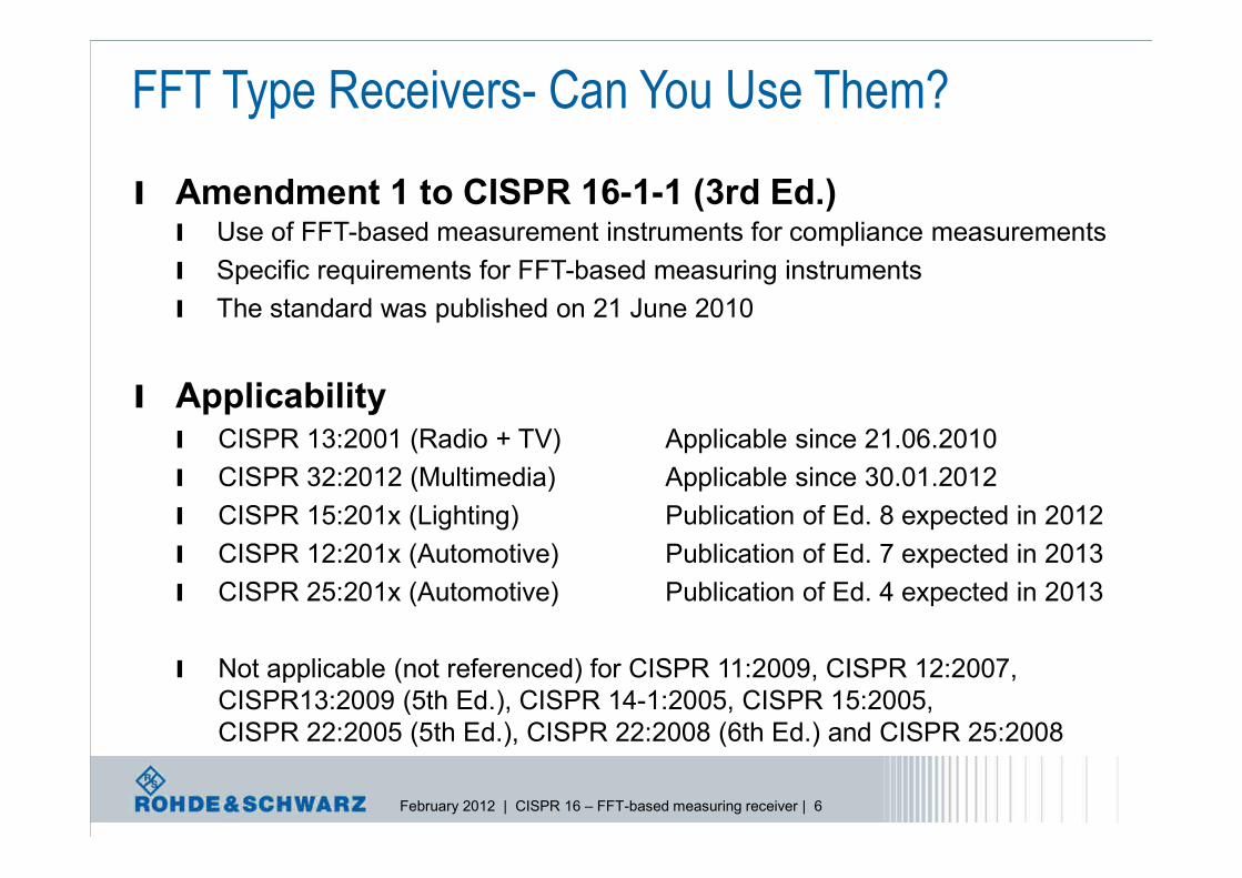
l Amendment 1 to CISPR 16-1-1 (3rd Ed.)l Use of FFT-based measurement instruments for compliance measurementsl Specific requirements for FFT-based measuring instrumentsl The standard was published on 21 June 2010
l Applicabilityl CISPR 13:2001 (Radio + TV) Applicable since 21.06.2010l CISPR 32:2012 (Multimedia) Applicable since 30.01.2012l CISPR 15:201x (Lighting) Publication of Ed. 8 expected in 2012l CISPR 12:201x (Automotive) Publication of Ed. 7 expected in 2013l CISPR 25:201x (Automotive) Publication of Ed. 4 expected in 2013
l Not applicable (not referenced) for CISPR 11:2009, CISPR 12:2007,CISPR13:2009 (5th Ed.), CISPR 14-1:2005, CISPR 15:2005,CISPR 22:2005 (5th Ed.), CISPR 22:2008 (6th Ed.) and CISPR 25:2008

February 2012 | CISPR 16 – FFT-based measuring receiver | 7
FFT Type Receivers- Can You Use Them?
l Real Answer is yes, use the FFT mode if you have it
l Verify results FFT vs Swept on golden device
l Know the time domain characteristics of the DUT
l At least use it during initial scan for time savings
l Can always use classic method for QP / Final meas

February 2012 | CISPR 16 – FFT-based measuring receiver | 8
l Definition of “measuring receiver” added:“instrument such as a tunable voltmeter, an EMI receiver, a spectrumanalyzer or an FFT-based measuring instrument, with or withoutpreselection, that meets the relevant parts of this standard”
l Specific requirement for FFT-based measuring instruments“for EMI measurements, FFT-based measuring instruments shall sampleand evaluate the signal continuously during themeasurement time”
CISPR 16-1-1 A1 (3rd Ed.)
Measurementreceiver
CISPR 16-1-1compliantmeasurements

February 2012 | CISPR 16 – FFT-based measuring receiver | 9
l Amendments to CISPR 16-2-1, 16-2-2 and 16-2-3 include measurementmethods for FFT-based receivers (6/7/2010)
l The duration of a disturbance must be knownl Can be measured using time domain outputs
l Zero spanl Oscilloscope on IF outputl Time Domain output of FFT
l Minimum measurement times Table for CW signals
has been added Same requirements as
for scanning receivers
Amendments to CISPR 16-2-x

February 2012 | CISPR 16 – FFT-based measuring receiver | 10
Amendments to CISPR 16-2-xl FFT-based instruments
(may) combine the parallelcalculation at N frequenciesand a stepped scan
l frequency range of interestis subdivided into severalsegments, which aremeasured sequentially
l The scan time Tscan is
l Tm is to be selectedlonger than the pulserepetition interval Tp
CISPR 16 – FFT-based measuring receivers

February 2012 | CISPR 16 – FFT-based measuring receiver | 11
l The discrete Fourier transform (DFT) is a numerical mathematicalmethod that calculates the spectrum for a periodic signal
l The fast Fourier transform (FFT) is an efficient algorithm to computethe DFT using symmetry and repetition propertiesl FFT is much faster than DFT due to reduced number of multiplications
l EMI signals include both periodic and transient signals and noisel Single FFT calculation will not be sufficient to model the EMI receiver
l Short-time FFT (STFFT) with a Gaussian window function is usedl Shows a discretization in both the frequency and time domainsl IF bandwidth requirements in the frequency domain are ideally met
(Fourier transform of a Gauss function in the time domain is a Gauss functionin the frequency domain)
l Gaussian window in time domain minimizes the leakage effects
Fourier Transforms – Frequency ‹› Time Domain

February 2012 | CISPR 16 – FFT-based measuring receiver | 12
F(s) f(t)
Frequency domainFrequency range to be measured issub-divided in consecutive frequencysegments and filtering
Time domainTemporal sampling of the filtered signals withhigh sampling rate/resolution
Discrete Fourier transform (DFT)Signal transformation of the filtered signalsfrom time domain to frequency domain
Frequency domainMerging the spectral distributions of all partialfrequency ranges
FFT-based receivers – digital signal processing
CISPR 16 – FFT-based measuring receivers

February 2012 | CISPR 16 – FFT-based measuring receiver | 13
l Exact calculation of the frequency spectrum would requirel Periodic / Repeating signalsl Measurement time equal to integer multiple of the signal period
l Disturbance characteristic of the signal is unknownl The frequency of the signal is not knownl The signal might not be periodicl The measurement time cannot be set as integer multiple of the signal periodl Spectral lines can exist between two discrete DFT frequency bins
l Signal distortions appearl leakage effect (signal spectrum becomes more wider),l picket fence effect (amplitude error sine wave signals)l Amplitude error for isolated pulse and a sequence of pulses
FFT Calculations Not Perfect

February 2012 | CISPR 16 – FFT-based measuring receiver | 14
l Convolution with window function yields wider spectrumi.e. shows additional spectral components
l Sidelobes (referred to as leakage effect)l These sidelobes should be suppressed by at least 40 dB
l A suitable windowing reduces the leakage effect (Gauss, Kaiser-Bessel)
Rectangular window and magnitude of the Fourier transform 1)
Sidelobes when using rectangular window or Gaussian window1) Tilman Butz, Fouriertransformation fuer Fußgaenger, ISBN 978-3-8351-0135-7
Gaussian window and magnitude of the Fourier transform, σ=2 1)
FFT Errors – Leakage Effect

February 2012 | CISPR 16 – FFT-based measuring receiver | 15
l The FFT calculates a discrete line spectrum at the frequency binsl If the sampled sine wave signal is at a frequency that doesn’t align with
a calculated frequency point an amplitude error appearsl The amplitude error is known as “picket fence effect”l Like stepped-frequency scan with wide IF bandwidth vs step size
time domain frequency domain
window width
FFT Errors – Picket Fence Effect

February 2012 | CISPR 16 – FFT-based measuring receiver | 16
l Measurement must be long enough to capture single pulsesl Sample/calculate process must be gapless during the meas time
l Without time domain overlap amplitude / detection problems
l An overlapping factor of >75%in the time domain is necessaryto meet the pulse amplitudespecification of CISPR 16-1-1
FFT Errors – Single Pulse Errors

February 2012 | CISPR 16 – FFT-based measuring receiver | 17
l Overlapping alsofixes pulsesequenceamplitude errors
l Example showsthe recalculatedIF signal fordifferent over-lapping factors
FFT Errors – Pulse Sequences0% overlap 25% overlap
90% overlap75% overlap

February 2012 | CISPR 16 – FFT-based measuring receiver | 18
R&S EMI Instruments with FFT Functions
ESU ESR
FSV / FSVRFSW

February 2012 | CISPR 16 – FFT-based measuring receiver | 19
EMI Receivers with FFTs
l High dynamic from 16-bit A/D converterl Frequency range not limited by the Nyquist criterion (Mixers + FFT)l Long maximum dwell time and high resolution (16k FFT length)l Use of receiver preselection, preamplifier, RF-attenuation
and detectors
l Use the best mode for test:l standard receiverl spectrum analyzerl IF – Receiver + Analyzerl FFT scanl Real-Timel Power meter
EMI Receiver R&S®ESR
Heterodyne EMI receivers with FFT applied to thewideband IF signal offer the following advantages:

February 2012 | CISPR 16 – FFT-based measuring receiver | 20
l Wideband switchable IF bandwidth preceding the A/D converter (ADC)l 16-bit / 128 MHz sampling ADC in combination with the preselector yields high
dynamic range to fulfil CISPR 16-1-1l Resampler for data reduction where needed (at narrower RBW)l Universal digital module (UMOD) saves the data in the 32 M-words RAM for
measurement times up to 100 s without any gap (depending on RBW)l Main processor accesses the RAM, applies a Gaussian window to the time
domain signal (to avoid leakage effects) and calculates the FFT
Block Diagram (ESR)Receiver
preselectionand mixer
WidebandIF filter
20,4 MHz
ADC Resample UMOD RAM
Mainprocessor

February 2012 | CISPR 16 – FFT-based measuring receiver | 21
ADC
A
f
fstartwindow width ≤ 7 MHz
"weighting"(detectors)
responselinearisation
ttresult f
Gaussian-type filtering
DFT≤ 7 MHz
f
"virtual step width" = ¼ x RBW
t
tmeas
tmeas
windowing(Gauss)
Maximum 90%overlapping intime domain
EMI receiver with FFT applied to the wideband IFEMI Test Receiver R&S®ESU

February 2012 | CISPR 16 – FFT-based measuring receiver | 22
l Capturing an impulse-type disturbance signal by an Gaussian-type FFTwindow reduces the signal amplitude at the window edges
l Overlap of the window function in the time domain minimizes thiserror and ensures that no impulse-type disturbance signal is missed
l R&S®ESU offers two different settings for time-domain scanl “Auto CW” mode
20% overlap in the time domainnarrowband signals are analyzed in the shortest possible time
l “Auto Pulse” modeapprox. 90% overlap in the time domainfor broadband-impulsive and mixed signalsensures that even very short impulse signalsat the edge of the Gaussian-type time-domainwindow are calculated withoutsignificant amplitude error
DFT
t
tmeasADC
Minimizing the FFT Errors – Leakage Effect
February 2012 | CISPR 16 – FFT-based measuring receiver | 23
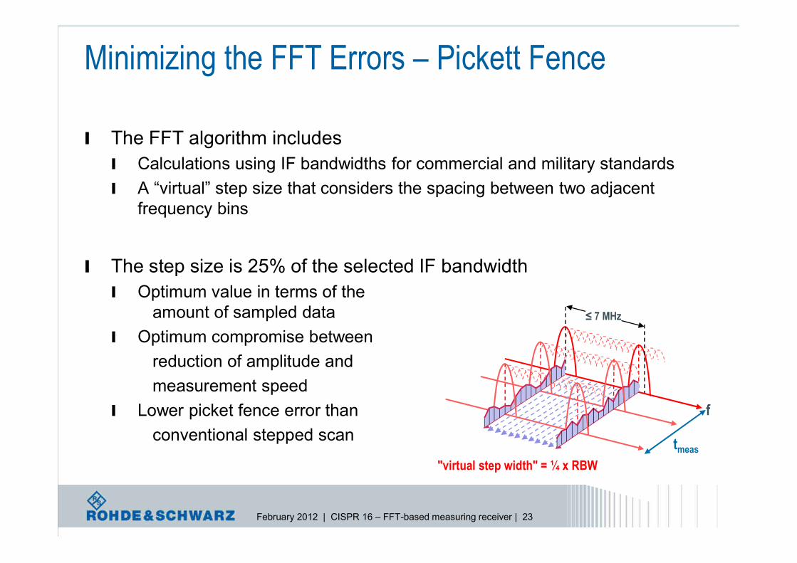
l The FFT algorithm includesl Calculations using IF bandwidths for commercial and military standardsl A “virtual” step size that considers the spacing between two adjacent
frequency bins
l The step size is 25% of the selected IF bandwidthl Optimum value in terms of the
amount of sampled datal Optimum compromise between
reduction of amplitude andmeasurement speed
l Lower picket fence error thanconventional stepped scan
≤ 7 MHz
f
"virtual step width" = ¼ x RBWtmeas
Minimizing the FFT Errors – Pickett Fence

February 2012 | CISPR 16 – FFT-based measuring receiver | 24
l R&S instruments provideboth scan methods usingthe same hardware andfirmware
l Measurement was doneusing a pulse generator forCISPR bands C and D
l Overall frequencyresponse (Detector =Max.Peak) shows that thedifferences between thetwo scan modes arenegligible
Time-Domain Scan versus Stepped Scan
Trace 1: Time-domain scan (blue)Trace 2: Stepped frequency scan (black)
<0.5 dB
Minimizing the FFT Errors
February 2012 | CISPR 16 – FFT-based measuring receiver | 25
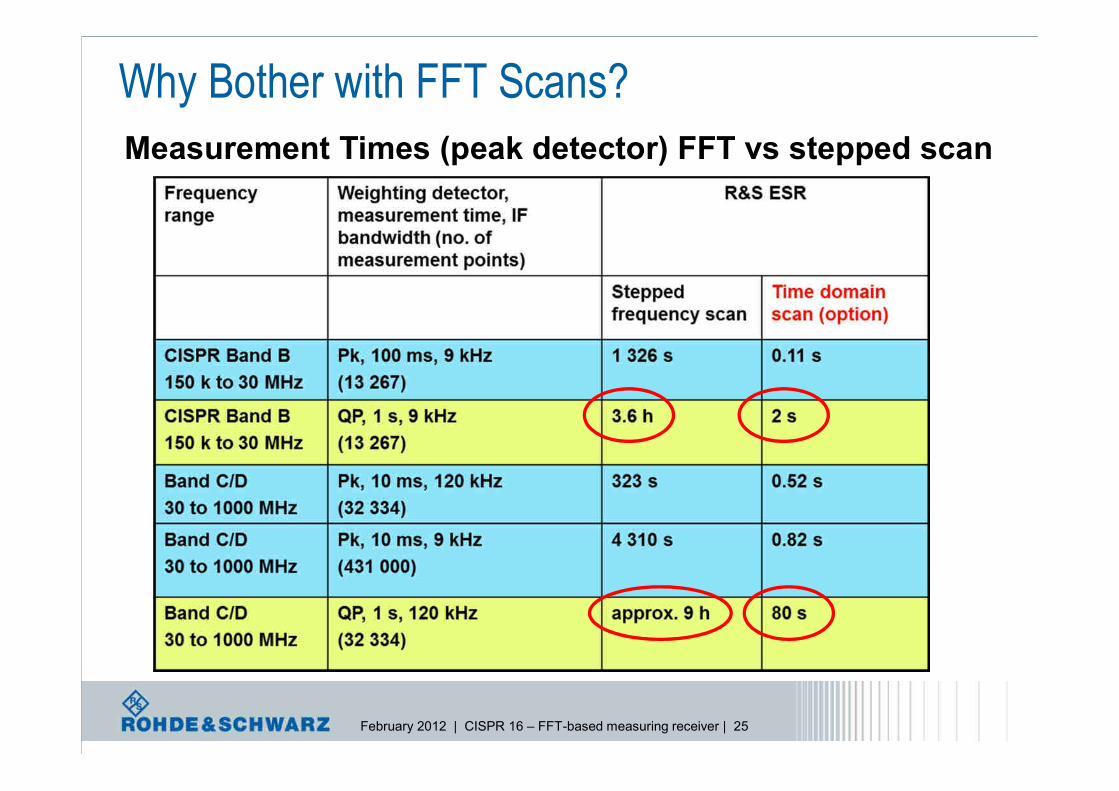
Why Bother with FFT Scans?Measurement Times (peak detector) FFT vs stepped scan

February 2012 | CISPR 16 – FFT-based measuring receiver | 26
l R&S®ESU (Stepped Scan)l 9 to 150 kHz; RBW 200 Hz; ∆f= 80 Hz; Tm = 20 ms: 74 sl 150 kHz to 30 MHz; RBW 9 kHz; ∆f= 4 kHz; Tm = 20 ms: 155 sl 30 to 1000 MHz; RBW 120 kHz; ∆f= 40 kHz; Tm = 10 ms: 247 sl 30 to 1000 MHz; RBW 9 kHz; ∆f= 4 kHz; Tm = 10 ms: 2 573 s
l R&S®ESU (Time-domain Scan)l 9 to 150 kHz; RBW 200 Hz; ∆f= 50 Hz; Tm = 20 ms: <1 sl 150 kHz to 30 MHz; RBW 9 kHz; ∆f= 2,25 kHz; Tm = 20 ms: 3 sl 30 to 1000 MHz; RBW 120 kHz; ∆f= 30 kHz; Tm = 10 ms: 13 sl 30 to 1000 MHz; RBW 9 kHz; ∆f= 2,25 kHz; Tm = 10 ms: 20 s
Comparison of typical Measurement Times (peak detector)Why Bother with FFT Scans?
Note: The frequency step of the FFT is RBW/4 to reduce the picket fence effect.Step mode = “Auto Pulse” with an overlap of >90% of the FFT window in the time domain.

February 2012 | CISPR 16 – FFT-based measuring receiver | 27
l Huge time savings vs conventional frequency (stepped) scansl 80 seconds vs. 9 hours for 30-1000 MHz / 120kHz IF / QP scanl .82 s vs. 4310 s for 30-1000 MHz / 9kHz IF / peak detector
l QP, CISPR-AV, RMS-AV are applicable in time-domain scan modesl Plus still have classic modes to compare if in doubt
l Preselection preserves the full dynamic range for band of interest
l Measurement time up to 100 s without any gapsl UMOD chip still allows zoom on any time window inside the capture
l Measurement of pulses without significant errorl 90% overlap (Auto Pulse) of the window function and gapless sampling
Summary: Benefits of FFT / Time Domain Scans

February 2012 | CISPR 16 – FFT-based measuring receiver | 28
Realtime analysis (option on ESR)Provides new insights for EMC diagnostics
l Spectrogram for seamlessspectrum display in the time domain
l Persistance modeValuable aid for examining signalsthat change over time. Impulsiveinterferers are clearly distinguishedfrom continuous interferers (seescreen shot)
l Frequency mask triggerResponds to events in thespectrum. Comparison with apredefined frequency mask.Violation of the frequency maskactivates the trigger event

February 2012 | CISPR 16 – FFT-based measuring receiver | 29
Thank you for your interest !