tipd qatar traffic manual & guidelines
TRANSCRIPT

8/9/2019 TIPD Qatar Traffic Manual & Guidelines
http://slidepdf.com/reader/full/tipd-qatar-traffic-manual-guidelines 1/197
MINISTRY OF MUNICIPALITY AND URBAN PLANNING
DOHA - QATAR
TRANSPORTATION AND INFRASTRUCTURE PLANNING DEPARTMENT
GUIDELINES AND PROCEDURES FOR TRANSPORT STUDIES
May 2011
REVISION 3
8/9/2019 TIPD Qatar Traffic Manual & Guidelines
http://slidepdf.com/reader/full/tipd-qatar-traffic-manual-guidelines 2/197
Guidelines and Procedures for Transport Studies
MMiinniisst t rryy oof f MMuunniicciippaalliit t yy aanndd UUrrbbaann PPllaannnniinngg Page II
TTrraannssppoorrt t aat t iioonn aanndd IInnf f rraasst t rruucct t uurree PPllaannnniinngg DDeeppaarrt t mmeennt t MMaayy 22001111
Document Control
Short title GUIDELINES AND PROCEDURES FOR TRANSPORT STUDIES
Authors: Osama Freija and Nabeel Al-Rawi
Version: Revision 3
Created on: February 2008
Last saved: 2/05/2011 by Nabeel Al-Rawi
Location saved:
Approvals Name Position Signed * Date
Author Osama Freija &
Nabeel Al-Rawi
Senior Traffic Engineers Original signed
Reviewer Nabeel Al-Rawi Senior Traffic Engineer Original signed
Approved for
Issue
Mohamed Abdah Original signed
Document Status
Rev No. Date Details Approved for Issue
0 20/02/2008 Original issue (Revision 0) Khalifa Buhazzaa
1 1/02/2009 Revision 1 Mohamed Abdah
2 15/05/2010 Revision 2 Mohamed Abdah
3 1/05/2011 Revision 3 Mohamed Abdah
4

8/9/2019 TIPD Qatar Traffic Manual & Guidelines
http://slidepdf.com/reader/full/tipd-qatar-traffic-manual-guidelines 3/197
Guidelines and Procedures for Transport Studies
MMiinniisst t rryy oof f MMuunniicciippaalliit t yy aanndd UUrrbbaann PPllaannnniinngg Page III
TTrraannssppoorrt t aat t iioonn aanndd IInnf f rraasst t rruucct t uurree PPllaannnniinngg DDeeppaarrt t mmeennt t MMaayy 22001111
TABLE OF CONTENTS
1 Introduction .................................................................................................1
1.1 Policy ....................................................................................................1
1.2
Objectives.............................................................................................
1
1.3 Preparing Transport Study/Assessment ................................................2
1.4 Benefits of Transport Studies ................................................................2
1.5 Applicability ...........................................................................................3
1.5.1 Development Projects ........................................................................ 4
1.5.2 Road Projects .....................................................................................7
1.5.3 Public Transport Projects ....................................................................7
1.5.4 Pedestrian and Cyclist Facilities Projects ........................................... 7
1.5.5
Car Parking Facilities Projects............................................................
7
1.5.6 Other Considerations ..........................................................................7
1.6 Definitions .............................................................................................8
1.7 References ...........................................................................................8
1.8 Approved Software Packages ...............................................................9
1.9 Minimum Requirements, Details and Information .................................. 9
1.10 Quality Assurance .................................................................................9
1.11 Intellectual Property and Public Information ........................................ 10
2 Transport Study Procedure .......................................................................11
2.1 Step 1 – Initial Communication ........................................................... 11
2.2 Step 2 - Appointment of Consultant .................................................... 11
2.3 Step 3 - Pre-application Meeting .........................................................12
2.4 Step 4 - Methodology Report ..............................................................12
2.5 Step 5 – Prestart/Initiation Meeting ..................................................... 13
2.6 Step 6 - Reviewing Development Plans and Reports .......................... 14
2.7 Step 7 - Preparation of Transport Study ..............................................15
2.8 Step 8 – Submission of Preliminary Analyses and Reports ................. 15
2.9
Step 9 - Draft Transport Study Submission.........................................
15
2.10 Step 10 - Final Submission .................................................................16
2.11 Step 11 - Road Network Improvement ................................................16
2.12 Step 12 – Approval .............................................................................17
2.13 Other Important Considerations ..........................................................17
3 Transport Study Methodology Report ........................................................18
3.1 Overview............................................................................................. 18
3.2 Methodology Report Outlines .............................................................. 19
3.2.1 Project/Development Location ..........................................................19
3.2.2 Project/ Development Description .....................................................19
8/9/2019 TIPD Qatar Traffic Manual & Guidelines
http://slidepdf.com/reader/full/tipd-qatar-traffic-manual-guidelines 4/197
Guidelines and Procedures for Transport Studies
MMiinniisst t rryy oof f MMuunniicciippaalliit t yy aanndd UUrrbbaann PPllaannnniinngg Page IV
TTrraannssppoorrt t aat t iioonn aanndd IInnf f rraasst t rruucct t uurree PPllaannnniinngg DDeeppaarrt t mmeennt t MMaayy 22001111
3.2.3 Transport Study Team ......................................................................21
3.2.4 Parking Generation Rates ................................................................ 21
3.2.5 Trip Generation Rates ...................................................................... 21
3.2.6 Sub-Area Model ...............................................................................22
3.2.7
Surrounding Area Conditions............................................................
22
3.2.8 Study Area ....................................................................................... 23
3.2.9 Traffic Assessment Methodology ......................................................24
3.2.10 Road safety Audit methodology ........................................................24
3.3 Review Period ....................................................................................25
3.4 Deliverables ........................................................................................25
4 Development/ Project Plans and Reports ..................................................26
4.1 Overview............................................................................................. 26
4.2 Development Plans .............................................................................26
4.3 Site Access and Traffic Circulation...................................................... 26
4.4 Car Parking .........................................................................................27
4.4.1 Parking Design .................................................................................27
4.4.2 Parking Circulation ........................................................................... 28
4.4.3 Parking Analysis ...............................................................................28
4.5 Pedestrian ..........................................................................................28
4.6 Bicycle ................................................................................................29
4.7 Public Transport ..................................................................................29
4.8
On-Site Planning and Parking Principles ............................................
29
4.8.1 Approach to Site Planning ................................................................29
4.8.2 Driveway Location ............................................................................30
4.8.3 Review of Driveways Access Plans .................................................. 30
4.8.4 Driveway Connection Depth / Throat Length .................................... 31
4.8.5 Driveway Angle of Connection: .........................................................31
4.8.6 On-Site Principles of Access Points ..................................................32
4.8.7 Vehicle Queuing Storage ..................................................................33
4.8.8
Internal Vehicular Circulation............................................................
33
4.8.9 Traffic Calming/Speed Control ..........................................................34
4.8.10 Service and Delivery Vehicles .......................................................... 35
4.8.11 Building Service Drives .....................................................................36
4.8.12 Signs and Pavement Markings ......................................................... 36
4.8.13 Parking .............................................................................................36
4.8.14 Pedestrian, Transit, Bicycle and Accessible Facilities....................... 37
4.8.15 Purpose and End Use ...................................................................... 37
4.9 Road Safety Audit ...............................................................................38
4.10
The Project/Development Review Report ...........................................
38
8/9/2019 TIPD Qatar Traffic Manual & Guidelines
http://slidepdf.com/reader/full/tipd-qatar-traffic-manual-guidelines 5/197
Guidelines and Procedures for Transport Studies
MMiinniisst t rryy oof f MMuunniicciippaalliit t yy aanndd UUrrbbaann PPllaannnniinngg Page V
TTrraannssppoorrt t aat t iioonn aanndd IInnf f rraasst t rruucct t uurree PPllaannnniinngg DDeeppaarrt t mmeennt t MMaayy 22001111
4.11 Review Period ....................................................................................38
4.12 Deliverables ........................................................................................39
5 Traffic Surveys and Data Collection .......................................................... 40
5.1 Overview............................................................................................. 40
5.2
Data Collection of Existing Roads.......................................................
40
5.3 Information and Data Collection of Transportation Projects ................ 42
5.4 Turning Movement Counts (TMC‘s) .................................................... 42
5.5 Automatic Traffic Counts (Machine/Tube Counts) ............................... 43
5.6 Manual Classified Counts (MCC‘s) ..................................................... 43
5.7 Parking Study and Survey .................................................................. 43
5.7.1 Parking Supply Survey ..................................................................... 44
5.7.2 Parking Accumulation Survey ...........................................................45
5.7.3 Parking Duration Survey ...................................................................45
5.8 Travel Time Survey .............................................................................45
5.9 Pedestrians and Cyclists Survey .........................................................46
5.10 Public Transport Survey ......................................................................46
5.11 Origin – Destination Survey ................................................................ 46
5.12 Land use Surveys and Investigations ..................................................47
5.13 Traffic Surveys Requirements .............................................................47
5.13.1 General: ...........................................................................................47
5.13.2 ATC‘s: ..............................................................................................47
5.13.3
TMC‘s:..............................................................................................
48
5.14 The Traffic Surveys Analyses Report ..................................................49
5.15 Review Period ....................................................................................49
5.16 Deliverables ........................................................................................50
6 VISUM Modeling and Update of the Transport Model ............................... 51
6.1 Overview............................................................................................. 51
6.2 Land Use ............................................................................................52
6.3 Planning Data .....................................................................................52
6.4
Distribution to Population Groups .......................................................
56
6.5 Planning and Network Assumptions.................................................... 58
6.5.1 Planning Assumptions ......................................................................58
6.5.2 Network Assumptions .......................................................................59
6.5.3 Public Transport Network ................................................................. 59
6.6 Modeling of Main Nodes .....................................................................59
6.6.1 TModel Methodology ........................................................................60
6.6.2 Junction Modeling............................................................................. 60
6.7 Latest Model Structure ........................................................................70
6.8
Model Directory (paths & settings)......................................................
70
8/9/2019 TIPD Qatar Traffic Manual & Guidelines
http://slidepdf.com/reader/full/tipd-qatar-traffic-manual-guidelines 6/197
Guidelines and Procedures for Transport Studies
MMiinniisst t rryy oof f MMuunniicciippaalliit t yy aanndd UUrrbbaann PPllaannnniinngg Page VI
TTrraannssppoorrt t aat t iioonn aanndd IInnf f rraasst t rruucct t uurree PPllaannnniinngg DDeeppaarrt t mmeennt t MMaayy 22001111
6.9 L6 Model Run .....................................................................................78
6.10 Demand model in the Latest Model Structure ..................................... 88
6.11 Procedure Parameter .......................................................................... 94
6.12 Network parameters ......................................................................... 100
6.13
Zone‘s Manipulation..........................................................................
104
6.13.1 Overview ........................................................................................104
6.13.2 Zones‘ Disaggregation within the VISUM Master File ..................... 105
6.13.3 Concerned Files and Steps outside VISUM Master File ................. 105
6.13.4 New Zones Numbering ...................................................................107
6.13.5 Adjustment to the Network: .............................................................108
6.13.6 Planning Data Submission ..............................................................108
6.14 Model Calibration and Validation ...................................................... 108
6.14.1 Replicate the Base Year Network ................................................... 109
6.14.2 Replicate the Base Year Land Use .................................................109
6.14.3 Identification of Residential Mega Generator Blocks in the Study Area 109
6.14.4 Trip Calibration Counts (ATCs) .......................................................110
6.14.5 Onsite Surveys at the Residential Mega Generator Locations ........ 111
6.14.6 Data Analysis .................................................................................111
6.14.7 Changes in Trip Distribution/Mode Choice Model Procedures ........ 111
6.14.8 Changes to Peak Hour Ratios ........................................................ 112
6.14.9
Changes to Time Series.................................................................
113
6.14.10 Trip Chain Rates ............................................................................ 114
6.14.11 Trip Generation Procedure Runs .................................................... 115
6.14.12 Trip Generation Analysis ................................................................ 115
6.14.13 Model Validation .............................................................................116
6.15 Study Area Update ........................................................................... 116
6.15.1 Study Area Boundary ..................................................................... 117
6.15.2 Land Use Update ........................................................................... 117
6.15.3 Zones‘ Disaggregation ....................................................................117
6.15.4 Micro-Simulation Sub area Boundary ............................................. 117
6.15.5 Traffic Surveys ............................................................................... 118
6.15.6 Alternative Transportation Modes ................................................... 118
6.15.7 Network ..........................................................................................119
6.15.8 General Modeling Procedures ........................................................ 119
6.15.9 Base Year Model ............................................................................121
6.15.10 Future Scenario Model ................................................................... 121
6.16 Congestion Pricing ............................................................................122
6.17
Model Development – MMUP Liaison...............................................
122
6.18 Traffic Design Volumes .....................................................................123
8/9/2019 TIPD Qatar Traffic Manual & Guidelines
http://slidepdf.com/reader/full/tipd-qatar-traffic-manual-guidelines 7/197
Guidelines and Procedures for Transport Studies
MMiinniisst t rryy oof f MMuunniicciippaalliit t yy aanndd UUrrbbaann PPllaannnniinngg Page VII
TTrraannssppoorrt t aat t iioonn aanndd IInnf f rraasst t rruucct t uurree PPllaannnniinngg DDeeppaarrt t mmeennt t MMaayy 22001111
6.19 Model Report ....................................................................................123
6.19.1 Model Description ...........................................................................123
6.19.2 Description of Data .........................................................................123
6.19.3 Networks Checks............................................................................ 123
6.19.4
Trip Matrix Validation......................................................................
123
6.19.5 Trip Assignment Validation .............................................................124
6.19.6 Validation of other Features ............................................................124
6.19.7 Target Years‘ Modeling .................................................................. 124
6.20 Review Period ..................................................................................124
6.21 Deliverables ......................................................................................124
7 Impact Assessment .................................................................................125
7.1 Overview........................................................................................... 125
7.2 Design Parameters ...........................................................................126
7.3 Assessment Criterion ........................................................................127
7.4 Traffic Assessment ...........................................................................127
7.4.1 Assessment of Existing Conditions .................................................127
7.4.2 Project Distribution and Assignment ............................................... 128
7.4.3 Future Background Traffic Conditions .............................................128
7.4.4 Future Conditions ...........................................................................128
7.4.5 Initial Intersection and Link Assessment ......................................... 129
7.5 SIDRA Assessment .......................................................................... 131
7.6
Synchro Assessment........................................................................
132
7.7 VISSIM Assessment .........................................................................133
7.7.1 Introduction..................................................................................... 134
7.7.2 Site Visits ....................................................................................... 135
7.7.3 Data Collection ...............................................................................135
7.7.4 Traffic Counts .................................................................................136
7.7.5 Peak Hour Choice .......................................................................... 136
7.7.6 Peak Hour Factor ........................................................................... 136
7.7.7
Public Transport Data Collection ....................................................
136
7.7.8 Coding the Model ...........................................................................136
7.7.9 Error Checking ............................................................................... 137
7.7.10 Calibration ......................................................................................137
7.7.11 Target Year Model Development .................................................... 142
7.7.12 Advance Micro-simulation ...............................................................143
7.7.13 Parking Micro-simulation ................................................................ 143
7.7.14 Other Parameters ...........................................................................144
7.7.15 Otput ..............................................................................................144
7.7.16
Volumes.........................................................................................
144
8/9/2019 TIPD Qatar Traffic Manual & Guidelines
http://slidepdf.com/reader/full/tipd-qatar-traffic-manual-guidelines 8/197
Guidelines and Procedures for Transport Studies
MMiinniisst t rryy oof f MMuunniicciippaalliit t yy aanndd UUrrbbaann PPllaannnniinngg Page VIII
TTrraannssppoorrt t aat t iioonn aanndd IInnf f rraasst t rruucct t uurree PPllaannnniinngg DDeeppaarrt t mmeennt t MMaayy 22001111
7.7.17 Travel Time, Speed, and Delay ...................................................... 144
7.7.18 Stops ..............................................................................................144
7.7.19 Density ...........................................................................................144
7.7.20 Queues ...........................................................................................144
7.7.21
Summarization of Results...............................................................
145
7.7.22 VISSIM Documentation Guide ........................................................146
7.8 Weaving Analysis ............................................................................. 150
7.9 Ramps Analysis ................................................................................150
7.10 Parking Analysis ...............................................................................150
7.11 Pedestrian Analysis .......................................................................... 150
7.11.1 Pedestrian Assessment ..................................................................150
7.11.2 Pedestrian Crossing Delay ............................................................. 151
7.12 Bicycle Analysis ................................................................................151
7.12.1 Bicycle Assessment ........................................................................152
7.13 Public Transport Analysis ................................................................. 152
7.13.1 Public Transport Assessment ......................................................... 152
7.14 Mitigation Measures ..........................................................................153
7.15 Recommendations and Options ........................................................153
7.16 Impact Assessment Report ...............................................................154
7.16.1 Description of Data .........................................................................154
7.16.2 Base Year Models Description and Analyses ................................. 154
7.16.3
Future Years Models Description and Analyses .............................
154
7.16.4 Summary of Base and Future Years Analyses ............................... 154
7.16.5 Conclusion of Base and Future years Analyses ..............................154
7.16.6 Mitigation Measures and Options ................................................... 154
7.16.7 Analyses of Mitigation Measures and Options ................................ 154
7.16.8 Conclusions and Recommendations .............................................. 154
7.17 Review Period ..................................................................................154
7.18 Deliverables ......................................................................................155
8
Reporting, Meetings and Presentation ....................................................
156
8.1 Format of the Traffic Impact Study .................................................... 156
8.1.1 Study Introduction........................................................................... 156
8.1.2 Defined Sub-Area Model ................................................................ 156
8.1.3 Defined Study Area ........................................................................ 156
8.1.4 Existing Conditions .........................................................................156
8.1.5 Project Traffic Generation ...............................................................157
8.1.6 Project Traffic Distribution ...............................................................157
8.1.7 Projection of Future Background Traffic ..........................................157
8.1.8
Future with Project Traffic...............................................................
157
8/9/2019 TIPD Qatar Traffic Manual & Guidelines
http://slidepdf.com/reader/full/tipd-qatar-traffic-manual-guidelines 9/197
Guidelines and Procedures for Transport Studies
MMiinniisst t rryy oof f MMuunniicciippaalliit t yy aanndd UUrrbbaann PPllaannnniinngg Page IX
TTrraannssppoorrt t aat t iioonn aanndd IInnf f rraasst t rruucct t uurree PPllaannnniinngg DDeeppaarrt t mmeennt t MMaayy 22001111
8.1.9 Capacity Analysis ...........................................................................157
8.1.10 Traffic Circulation Issues ................................................................ 157
8.1.11 Parking Analysis .............................................................................157
8.1.12 Weaving Analysis ...........................................................................157
8.1.13
Road Safety Audit...........................................................................
157
8.1.14 Conclusions ....................................................................................157
8.1.15 Recommendations .......................................................................... 157
8.1.16 Appendices..................................................................................... 158
8.2 Review Period ..................................................................................158
8.3 Deliverables ......................................................................................158
Appendix A ............................................................................................................159
Concept Design Submittal and Review Guidelines ................................................159
Appendix B ............................................................................................................168
Context Sensitive Design/Solutions CSD/CSS ...................................................... 168
1. Introduction .............................................................................................169
2. Streets as Places ....................................................................................170
3. Detailing the public realm ........................................................................171
4. Multi modal streets ..................................................................................172
5. The CSS Product: Qualities of Excellence in Transportation Design ....... 174
6. Urban Design Involvement In Design Development ................................ 175
7. Urban Design Technical Criteria for Tender Submissions ....................... 177
8.
Urban Design Technical Brief ..................................................................
178
9. Urban Design Scope of Work ..................................................................179
Appendix C ...........................................................................................................186
Parking Design Guidelines ....................................................................................186
Appendix D ...........................................................................................................187
Pedestrian Facilities Design Guidelines................................................................. 187
Appendix E ............................................................................................................188
Bicycle Facilities Design Guidelines ...................................................................... 188
8/9/2019 TIPD Qatar Traffic Manual & Guidelines
http://slidepdf.com/reader/full/tipd-qatar-traffic-manual-guidelines 10/197
Guidelines and Procedures for Transport Studies
MMiinniissttr r yy oof f MMuunniicciippaalliittyy aanndd UUr r bbaann PPllaannnniinngg PPaaggee 11
TTr r aannssppoor r ttaattiioonn aanndd IInnf f r r aassttr r uuccttuur r ee PPllaannnniinngg DDeeppaar r ttmmeenntt MMaayy 22001111
1 INTRODUCTION
Transport Studies and assessments are necessary tool in the analysis and mitigationof the potential impacts of new land use developments and new projects on roadway
traffic flow and on sites adjacent to the roadway. The nature of the impacts, and whatto do about mitigating those impacts, are the subject of this guidance.
This guidance gives applicants, developers, consultants and Ministry of Municipalityand Urban Planning (MMUP) staff a better understanding of how to prepare anassessment study together with an appreciation of the various factors involved in itspreparation. These studies are placed in the overall context of development control.
This guidance can be used as a legal foundation to assist the MMUP to assessdevelopment applications, and imposing on developers the responsibility to addressthoroughly concerns about impacts on traffic-flow, the environment, non-motorizedtravel and roadway safety due to their projects. All relevant impacts are to beidentified and assessed and appropriate action should be taken to ameliorate the effect
of any such impact.
New developments and projects invariably introduce new impacts so it is essentialthat any proposed development can be fitted into the existing urban environmentwithout imposing undesirable effects on transport capacity, traffic congestion androad safety for all users. Benefits of conducting an impact study accrue to developers,the general population and the State of Qatar.
1.1 Pol icy
The following guidelines and procedures are established for the administration of the
Review and Approval process by the Ministry of Municipality and Urban Planning(MMUP) of:
a. Transport Impact Studies (TIS) submitted by Applicants/ Developers aspart of planning approval for proposed development.
b. Transport Studies (TS) submitted by Consultants as part of the designprocess of new highway project or the upgrading of existingroads/highways.
c. Transport Impact Studies (TIS) submitted by Consultants as part of thedesign process of new subdivision projects or the upgrading of existingroad network within an established area.
The guidelines included in this document are considered as the minimumrequirements for the Transport Studies and MMUP have the right to impose anyadditional requirements or conditions at any stage during or after the study periodbased on the proposed development and project location, size and effects on theadjacent and surrounding roads network.
1.2 Objectives
The objectives of Transport Studies are to:
Ensure that all new developments and projects within the State of Qatar have
proper, adequate and safe accesses, for all modes of transport, from theadjacent road and transport networks.
8/9/2019 TIPD Qatar Traffic Manual & Guidelines
http://slidepdf.com/reader/full/tipd-qatar-traffic-manual-guidelines 11/197
Guidelines and Procedures for Transport Studies
MMiinniissttr r yy oof f MMuunniicciippaalliittyy aanndd UUr r bbaann PPllaannnniinngg PPaaggee 22
TTr r aannssppoor r ttaattiioonn aanndd IInnf f r r aassttr r uuccttuur r ee PPllaannnniinngg DDeeppaar r ttmmeenntt MMaayy 22001111
Determine the traffic impact generated by the proposed development on theproject means of ingress and egress access points, intersections, andadjacent road network and intersections.
Determine the specific traffic and parking problems generated by theproposed development.
Determine the roadway and/or intersection improvements required to alleviatethe generated traffic problems.
Determine the cost of the improvements needed to alleviate the generatedtraffic problems.
Determine opportunities to improve on-site and off-site traffic circulation andparking facilities.
Determine opportunities to improve pedestrians and cyclists facilities withinand around the proposed development.
Determine opportunities to improve public transport facilities and connection
within the proposed development area.
Determine safety risks to all road users and measures to alleviate these risks.
1.3 Preparing Transport Study/Assessm ent
A properly prepared assessment will present the transport implications of theproposed project and will identify suitable measures to achieve a more sustainableand environmentally sound outcome. In preparing for an assessment the developershould consider the following objectives:
Reducing the need for travel, reducing the length of the trips and promoting
multi-purpose or linked trips by achieving a more sustainable patterns ofdevelopment;
Improving sustainable transport choices, by making it safer and easier forpeople to access jobs, shopping, leisure facilities and services by publictransport, walking and bicycling;
Exploring reduction in car usage by utilizing demand management solutions(car-sharing, car pooling, parking control, etc.);
Maximizing the capacity resources of the existing transport infrastructurethrough advance intelligent transport system technologies;
Maximizing the extent to which the new development can be made to fit into
the available capacity by managing access from the development into thetransport network; and
Mitigating residual impacts and increase capacities through transport controlmeasures across the network, extend transit routes and service frequency,facilitate walking and bicycling, and improve geometry and operations of junctions and roadways.
1.4 Benef i ts of Transport Studies
New developments and projects introduce new impacts. Therefore, it is essential
that any proposed development be fitted into the existing urban environment withoutimposing undesirable effects on roadway capacity, traffic congestion and roadway
8/9/2019 TIPD Qatar Traffic Manual & Guidelines
http://slidepdf.com/reader/full/tipd-qatar-traffic-manual-guidelines 12/197
Guidelines and Procedures for Transport Studies
MMiinniissttr r yy oof f MMuunniicciippaalliittyy aanndd UUr r bbaann PPllaannnniinngg PPaaggee 33
TTr r aannssppoor r ttaattiioonn aanndd IInnf f r r aassttr r uuccttuur r ee PPllaannnniinngg DDeeppaar r ttmmeenntt MMaayy 22001111
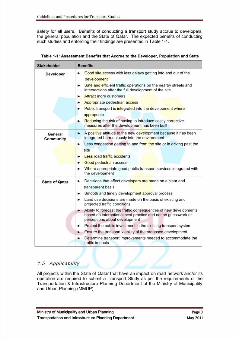
safety for all users. Benefits of conducting a transport study accrue to developers,the general population and the State of Qatar. The expected benefits of conductingsuch studies and enforcing their findings are presented in Table 1-1.
Table 1-1: Assessment Benefits that Accrue to the Developer, Population and State
Stakeholder Benefits
Developer ► Good site access with less delays getting into and out of the
development
► Safe and efficient traffic operations on the nearby streets and
intersections after the full development of the site
► Attract more customers
► Appropriate pedestrian access
► Public transport is integrated into the development where
appropriate
► Reducing the risk of having to introduce costly correctivemeasures after the development has been built
GeneralCommunity
► A positive attitude to the new development because it has beenintegrated harmoniously into the environment
► Less congestion getting to and from the site or in driving past the
site
► Less road traffic accidents
► Good pedestrian access
► Where appropriate good public transport services integrated withthe development
State of Qatar ► Decisions that affect developers are made on a clear and
transparent basis
► Smooth and timely development approval process
► Land use decisions are made on the basis of existing andprojected traffic conditions
► Ability to forecast the traffic consequences of new developmentsbased on international best practice and not on guesswork or
perceptions about development
► Protect the public investment in the existing transport system
► Ensure the transport viability of the proposed development
► Determine transport improvements needed to accommodate thetraffic impacts
1.5 Appl icabi l i ty
All projects within the State of Qatar that have an impact on road network and/or itsoperation are required to submit a Transport Study as per the requirements of theTransportation & Infrastructure Planning Department of the Ministry of Municipalityand Urban Planning (MMUP).
8/9/2019 TIPD Qatar Traffic Manual & Guidelines
http://slidepdf.com/reader/full/tipd-qatar-traffic-manual-guidelines 13/197
Guidelines and Procedures for Transport Studies
MMiinniissttr r yy oof f MMuunniicciippaalliittyy aanndd UUr r bbaann PPllaannnniinngg PPaaggee 44
TTr r aannssppoor r ttaattiioonn aanndd IInnf f r r aassttr r uuccttuur r ee PPllaannnniinngg DDeeppaar r ttmmeenntt MMaayy 22001111
1.5.1 Development Projects
Transport Study (Traffic Impact Study) shall be prepared and submitted to MMUP forreview and approval for any project or development generates trips more than 100vehicles during any peak hour of the day. For multi-staged projects or developmentsthe threshold vehicle trips shall be based on the total trips generated by combining allstages of the development.
Transport study shall be prepared and submitted to MMUP for review and approvalfor all projects or developments affecting the road network in the following areas:
Safety
Right Of Way (ROW) / Road Corridor
Number of lanes
The configuration of roads, intersections, interchanges, etc.
Parking
Pedestrian and cyclist
Land use
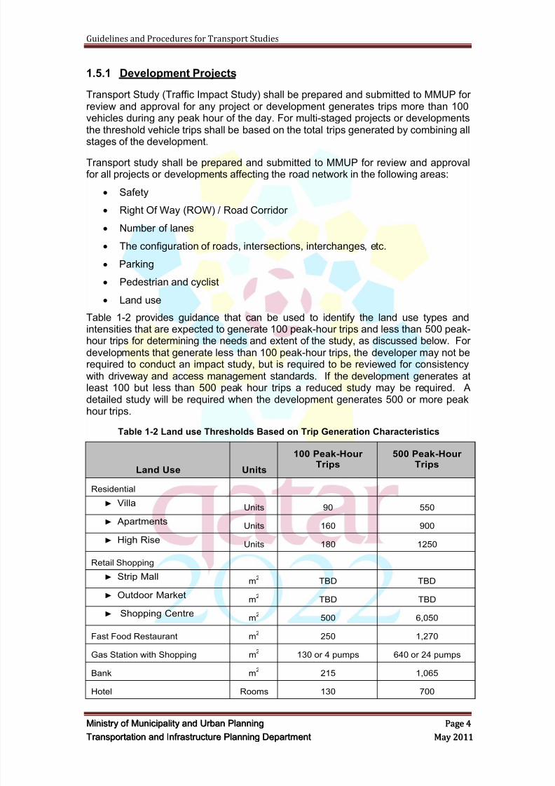
Table 1-2 provides guidance that can be used to identify the land use types andintensities that are expected to generate 100 peak-hour trips and less than 500 peak-hour trips for determining the needs and extent of the study, as discussed below. Fordevelopments that generate less than 100 peak-hour trips, the developer may not berequired to conduct an impact study, but is required to be reviewed for consistencywith driveway and access management standards. If the development generates atleast 100 but less than 500 peak hour trips a reduced study may be required. Adetailed study will be required when the development generates 500 or more peak
hour trips.
Table 1-2 Land use Thresholds Based on Trip Generation Characteristics
Land Use Units
100 Peak-HourTrips
500 Peak-HourTrips
Residential
► VillaUnits 90 550
► ApartmentsUnits 160 900
► High RiseUnits 180 1250
Retail Shopping
► Strip Mallm
2TBD TBD
► Outdoor Marketm
2 TBD TBD
► Shopping Centrem
2 500 6,050
Fast Food Restaurant m2 250 1,270
Gas Station with Shopping m2 130 or 4 pumps 640 or 24 pumps
Bank m2 215 1,065
Hotel Rooms 130 700
8/9/2019 TIPD Qatar Traffic Manual & Guidelines
http://slidepdf.com/reader/full/tipd-qatar-traffic-manual-guidelines 14/197
Guidelines and Procedures for Transport Studies
MMiinniissttr r yy oof f MMuunniicciippaalliittyy aanndd UUr r bbaann PPllaannnniinngg PPaaggee 55
TTr r aannssppoor r ttaattiioonn aanndd IInnf f r r aassttr r uuccttuur r ee PPllaannnniinngg DDeeppaar r ttmmeenntt MMaayy 22001111
Office
► Single storym
2 2,400 11,750
► High Risem
2 4,030 35,600
Light Industry m2 n/a 43,000
Manufacturing m2 12,450 62,000
Sources: United States, Australia and United Kingdom
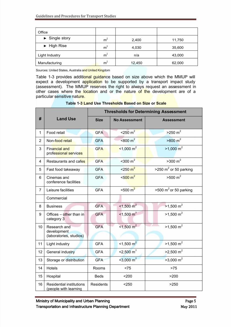
Table 1-3 provides additional guidance based on size above which the MMUP willexpect a development application to be supported by a transport impact study(assessment). The MMUP reserves the right to always request an assessment inother cases where the location and or the nature of the development are of aparticular sensitive nature.
Table 1-3 Land Use Thresholds Based on Size or Scale
# Land Use
Thresholds for Determining Assessment
Size No Assessment Assessment
1 Food retail GFA <250 m2 >250 m
2
2 Non-food retail GFA <800 m2 >800 m
2
3 Financial andprofessional services
GFA <1,000 m2 >1,000 m
2
4 Restaurants and cafes GFA <300 m2 >300 m
2
5 Fast food takeaway GFA <250 m2 >250 m
2 or 50 parking
6 Cinemas andconference facilities
GFA <500 m2 >500 m
2
7 Leisure facilities GFA <500 m2 >500 m
2or 50 parking
Commercial
8 Business GFA <1,500 m2 >1,500 m
2
9 Offices – other than incategory 3
GFA <1,500 m2 >1,500 m
2
10 Research anddevelopment(laboratories, studios)
GFA <1,500 m2 >1,500 m
2
11 Light industry GFA <1,500 m2 >1,500 m
2
12 General industry GFA <2,500 m2 >2,500 m
2
13 Storage or distribution GFA <3,000 m2 >3,000 m
2
14 Hotels Rooms <75 >75
15 Hospital Beds <200 >200
16 Residential institutions(people with learning
Residents <250 >250

8/9/2019 TIPD Qatar Traffic Manual & Guidelines
http://slidepdf.com/reader/full/tipd-qatar-traffic-manual-guidelines 15/197
Guidelines and Procedures for Transport Studies
MMiinniissttr r yy oof f MMuunniicciippaalliittyy aanndd UUr r bbaann PPllaannnniinngg PPaaggee 66
TTr r aannssppoor r ttaattiioonn aanndd IInnf f r r aassttr r uuccttuur r ee PPllaannnniinngg DDeeppaar r ttmmeenntt MMaayy 22001111
# Land Use
Thresholds for Determining Assessment
Size No Assessment Assessment
disabilities)
17 Education Students <250 >250
18 Stadium Seats <1,500 >1,500
19 Residential housing Dwellings <50 >50
20 Medical and healthservices
GFA <500 m2 >500 m
2
21 Museum, library, artgalleries, non-residential education,training centre and
places of worship
GFA <500 m2 >500 m
2or 50 parking
22 Any development thatis not in conformitywith the adopted plan
TBD All
23 Mixed use GFA <500 m2
>500 m2
24 Freight movements Weight <7.5 tonnes >7.5 tonnes
25 Any development thatis likely to increaseaccidents or transportconflicts
TBD All
26 Two-way vehiclemovements: peakhour and peak day
Vehicles >30 peak hour
>100 peak day
27 Parking Spaces >100
28 Any developmentgenerating significantfreight movements
TBD All
29 Inadequate transportinfrastructure
(roadway, transit,bicycle and pedestrian
TBD All
30 Noise, air quality andwater pollution)
TBD Discuss withUPDA
Discuss with UPDA
31 Impact on utilities(water, sewer, powertelecommunication)
TBD Discuss withUPDA
Discuss with UPDA
32 Impact on community(scenic, historic,archaeological andrecreation)
TBD Discuss withUPDA
Discuss with UPDA
8/9/2019 TIPD Qatar Traffic Manual & Guidelines
http://slidepdf.com/reader/full/tipd-qatar-traffic-manual-guidelines 16/197
Guidelines and Procedures for Transport Studies
MMiinniissttr r yy oof f MMuunniicciippaalliittyy aanndd UUr r bbaann PPllaannnniinngg PPaaggee 77
TTr r aannssppoor r ttaattiioonn aanndd IInnf f r r aassttr r uuccttuur r ee PPllaannnniinngg DDeeppaar r ttmmeenntt MMaayy 22001111
1.5.2 Road Projects
Transport Study shall be prepared and submitted to MMUP for review and approvalfor all new and/or upgrade road projects which includes intersections, interchanges,roads, ramps, on-street car parking facilities, etc.
1.5.3 Public Transport Projects
Transport study shall be prepared and submitted to MMUP for review and approvalfor all new and upgrade public transport projects that affecting the road network inthe following areas:
Safety
Right Of Way (ROW) / Road Corridor
Traffic volume
Number of lanes
The configuration of roads, intersections, interchanges, etc.
Parking
Pedestrian and cyclist
Land use
1.5.4 Pedestrian and Cyclist Facilities Projects
Transport Study shall be prepared and submitted to MMUP for review and approvalfor all new and upgrade pedestrian and cyclist facilities.
1.5.5 Car Parking Facilities Projects
Transport Study shall be prepared and submitted to MMUP for review and approvalfor all new and upgrade car parking facilities such as temporary car parking areas,multi-storey car parks, etc.
1.5.6 Other Considerations
In some cases, although a development might generate fewer trips or be a smallersize than the established 100 vehicles during peak hour of the day threshold, a
localized safety or capacity deficiency may necessitate a study for one or more of thefollowing reasons:
Existing transport problems in the local area, such as a high accident location,complex intersection geometrics, or an intersection in need of a traffic signal;
Significant impacts to the current or projected level of service or theoperational characteristics of the roadway system adjacent to thedevelopment;
Sensitivity of the adjacent neighborhoods or other areas that may beperceived as being impacted;
Proximity of site driveways to other driveways or intersections;
8/9/2019 TIPD Qatar Traffic Manual & Guidelines
http://slidepdf.com/reader/full/tipd-qatar-traffic-manual-guidelines 17/197
Guidelines and Procedures for Transport Studies
MMiinniissttr r yy oof f MMuunniicciippaalliittyy aanndd UUr r bbaann PPllaannnniinngg PPaaggee 88
TTr r aannssppoor r ttaattiioonn aanndd IInnf f r r aassttr r uuccttuur r ee PPllaannnniinngg DDeeppaar r ttmmeenntt MMaayy 22001111
Ability of the adjacent existing or planned roadway system to handleincreased traffic, or the feasibility of improving the roadway system to handleincreased traffic;
Need for pedestrian and bicycle access and safe movement;
Initiation of public transport service with stops that generate traffic andpedestrian volumes; and
Other specific problems or deficiencies that may be affected by the proposeddevelopment.
1.6 Defini t ions
For the purpose of this document:
The terms "Municipality‖ or ―MMUP" shall mean the Ministry of Municipalityand Urban Planning.
The term "UPDS" shall mean the Urban Planning and Development Sector ofthe MMUP.
The terms "Department‖ shall mean the Transportation & InfrastructurePlanning Department of UPDS.
The term "Section" shall mean the Traffic and Transportation PlanningSection of the Transportation & Infrastructure Planning Department.
The term "Applicant" shall mean any applicant/developer/consultant (orhis/her representative) for a development permit subject to the transport studyrequirements.
The term "Consultant" refers to the Transport Study consultant.
Note: Any reference within this document or other related documents to UPDA(Urban Planning and Development Authority) shall be changed to MMUP.
1.7 References
The consultant shall use the latest release of the following references whenpreparing and submitting the transport study and report:
Transport Master Plan for Qatar (TMPQ) ل قط موري
(Qatar Traffic Manual)
Dubai Trip Generation and Parking Rates Manual
Dubai Traffic Impact Studies Guidelines
Highway Capacity Manual (HCM)
Trip Generation Handbook, Institute of Transportation Engineers (ITE)
Qatar Highway Design Manual (QHDM)
Concept Design Submittal and Review Guidelines, (MMUP)
TMPQ Parking Design Guidelines, (MMUP)
8/9/2019 TIPD Qatar Traffic Manual & Guidelines
http://slidepdf.com/reader/full/tipd-qatar-traffic-manual-guidelines 18/197
Guidelines and Procedures for Transport Studies
MMiinniissttr r yy oof f MMuunniicciippaalliittyy aanndd UUr r bbaann PPllaannnniinngg PPaaggee 99
TTr r aannssppoor r ttaattiioonn aanndd IInnf f r r aassttr r uuccttuur r ee PPllaannnniinngg DDeeppaar r ttmmeenntt MMaayy 22001111
TMPQ Pedestrian Design Guidelines, (MMUP)
TMPQ Bicycle Design Guidelines, (MMUP)
Any other regional and international manuals and guidelines that areaccepted by MMUP.
1.8 App roved Software Packages
Software packages approved by MMUP are:
VISUM
VISSIM
Synchro
SIDRA
TRANSYT F7
HCS+
AutoTURN
ParkCAD
The Consultant is required to:
a. Use the latest version of these packages and state the version number inthe report,
b. Discuss and agree with MMUP on the appropriateness of these packagesfor the specific project, and
c. Discuss and agree with MMUP on the parameters used in thesepackages.
1.9 Minimum Requirements, Detai ls and Inform ation
The requirements, procedures and analyses included in this document consideredthe minimum requirements that MMUP will be requested in any Transport Study.Depending on the size, location, function, etc. of the proposed project ordevelopment, MMUP might request additional requirements, procedures andanalyses to be included or explored in the Transport Study.
In addition any unclear details should be discussed with MMUP prior to theimplementation of any assumption. MMUP reserves the right of adjusting through theproject methodology any of the mentioned requirements, if technically required toachieve the objectives of the TS.
1.10 Qual i ty As sur ance
Many consulting companies have formal quality assurance programs in place. Thisrequires work to a high professional standard. The MMUP therefore expects that, at aminimum, the consultants shall:
Undertake a site visit;

8/9/2019 TIPD Qatar Traffic Manual & Guidelines
http://slidepdf.com/reader/full/tipd-qatar-traffic-manual-guidelines 19/197
Guidelines and Procedures for Transport Studies
MMiinniissttr r yy oof f MMuunniicciippaalliittyy aanndd UUr r bbaann PPllaannnniinngg PPaaggee 1100
TTr r aannssppoor r ttaattiioonn aanndd IInnf f r r aassttr r uuccttuur r ee PPllaannnniinngg DDeeppaar r ttmmeenntt MMaayy 22001111
List all assumptions, data sources and calculations used to arrive at theconclusions and recommendations in the transport study;
Ensure that the work meets all requirements specified in the approvedmethodology report;
Prepare a report that accurately describes the proposal, concisely documentsthe methodologies, clearly identifies impacts and their mitigation, andsuccinctly presents findings and makes recommendations; and
Make a presentation to the assessment panel on the findings andrecommendations, if so requested.
1.11 Intel lectu al Property and Publ ic Information
On submission of the final report, the intellectual property resides with the MMUP.The assessment studies, including data and written reports, enter the public domainupon submittal. It is important therefore to reference the report accurately according
to internationally-accepted, scientific standards (including specific page, figure andtable reference). In particular, the original sources of re-used information should becited when taken from previous studies undertaken in the State of Qatar. Informationin the transport studies may be used by MMUP, or other consultants, who may bepreparing subsequent studies. In this way, a credible and cross-referenced database can be built up over time as a major resource in transport planning for the Stateof Qatar.
8/9/2019 TIPD Qatar Traffic Manual & Guidelines
http://slidepdf.com/reader/full/tipd-qatar-traffic-manual-guidelines 20/197
Guidelines and Procedures for Transport Studies
MMiinniissttr r yy oof f MMuunniicciippaalliittyy aanndd UUr r bbaann PPllaannnniinngg PPaaggee 1111
TTr r aannssppoor r ttaattiioonn aanndd IInnf f r r aassttr r uuccttuur r ee PPllaannnniinngg DDeeppaar r ttmmeenntt MMaayy 22001111
2 TRANSPORT STUDY PROCEDURE
Applicants for development and transport projects that meet the Transport Study (TS)criteria or as directed by MMUP shall submit a Transport Study defining the impacts
of the proposed project on the adjacent and surrounding transportation network andrecommend the necessary related improvements.
In order to ensure that the project is properly reviewed and all traffic impacts aredetermined and mitigated, Applicants shall adhere to the following steps:
2.1 Step 1 – Ini t ia l Comm unicat ion
1. Contact the Transportation and Infrastructure Planning Department to confirmthat a Transport Study is required for the development / project. TheDepartment will assign a project coordinator/representative to the project.
2. It is critical that the developer discuss the project with the MMUP assignedreviewer early in the process. A clear understanding of the required level ofdetail and the assumptions required for the analysis will be determined at thistime. In addition, the developer will be able to obtain or verify the availabilityof the following study area information:
a. Available traffic counts,
b. Bus, bicycle and pedestrian facilities and usage,
c. Committed and planned roadway improvements,
d. Development and background traffic data,
e. Applicable policies,
f. Existing congested locations,
g. Data for locations with high accident rates,
h. Traffic signal systems,
i. Local area sensitivities,
j. Temporary conditions that affect the analysis.
2.2 Step 2 - App ointm ent of Consu l tant
1. The Applicant shall select, appoint and submit to MMUP for approval qualifiedengineering consultant(s) or professional engineering personnel that will beresponsible for undertaking the following tasks:
a. Data collections and traffic surveys
b. Preparation of the Transport Study
c. Preparation of site plans including parking, circulation, roads andintersections design, pedestrian and cyclist facilities design, linemarkingsand signs
d. Preparation of mitigation measures plans
e. Road Safety Audit
8/9/2019 TIPD Qatar Traffic Manual & Guidelines
http://slidepdf.com/reader/full/tipd-qatar-traffic-manual-guidelines 21/197
Guidelines and Procedures for Transport Studies
MMiinniissttr r yy oof f MMuunniicciippaalliittyy aanndd UUr r bbaann PPllaannnniinngg PPaaggee 1122
TTr r aannssppoor r ttaattiioonn aanndd IInnf f r r aassttr r uuccttuur r ee PPllaannnniinngg DDeeppaar r ttmmeenntt MMaayy 22001111
2. MMUP requires that the following personnel be part of the Transport StudyTeam:
a. Traffic/transport engineer/planner with at least 8 years of professionalexperience in traffic/transport engineering and similar projects.
b. Traffic/transport engineer/manager with at least 15 years of professionalexperience in traffic/transport engineering and similar projects.
c. Road design engineer with at least 15 years of professional experience insimilar projects.
d. Road safety auditor with a minimum of 8 years of professional experiencewith working experience in at least 5 similar projects.
e. Road safety audit reviewer with a minimum of 15 years of professionalexperience with working experience in at least 10 similar projects.
3. All personnel involve or participate in the Transport Study shall be qualified,professional and have relevant working experience.
2.3 Step 3 - Pre-appl icatio n Meeting
A pre-application meeting shall be scheduled between the Applicant, Consultant andMMUP staff involved in the Transport Study. In this meeting the following item will bediscussed:
a. The concept of the proposed development/project. The Consultant shallprepare and provide all the required information and plans
b. The requirements stipulated in this guidelines‘ document
c. The proposed Methodology Report for the TS
2.4 Step 4 - Method olo gy Report
1. The Consultant shall prepare a detailed report outlining the methodology tobe used in developing the TS. The proposed methodology shall consider allitems outlined in Section 3 of this document.
2. The Consultant shall submit the final methodology report officially via mail tothe Ministry of Municipality and Urban Planning, Transportation &Infrastructure Planning Department.
3. All related clarifications and assumptions requested by MMUP staff at the pre-application meeting need to be included in the methodology scope andfinalized by the Consultant prior to MMUP final acceptance of themethodology report.
4. For development projects, the Consultant shall provide evidence that abuilding application has already been launched with the relevant department.
5. MMUP will not review and approve any Transport Study unless themethodology report was previously reviewed and accepted by MMUP.
8/9/2019 TIPD Qatar Traffic Manual & Guidelines
http://slidepdf.com/reader/full/tipd-qatar-traffic-manual-guidelines 22/197
Guidelines and Procedures for Transport Studies
MMiinniissttr r yy oof f MMuunniicciippaalliittyy aanndd UUr r bbaann PPllaannnniinngg PPaaggee 1133
TTr r aannssppoor r ttaattiioonn aanndd IInnf f r r aassttr r uuccttuur r ee PPllaannnniinngg DDeeppaar r ttmmeenntt MMaayy 22001111
2.5 Step 5 – Prestart/Ini t iat ion Meeting
1. When the proposed methodology report has been received and reviewed byMMUP staff a methodology report development meeting will be organized.The purpose of this initiation meeting is to bring the applicant and consultants
and the MMUP staff together to ensure there is collective understanding ofthe scope of the transport study before the study commences.
2. A prestart meeting shall be held prior to the commencement of any datacollection and analyses. The objectives of the prestart meeting are to:
a. Discuss the submitted methodology report
b. Assess the anticipated traffic impact of the proposed development on thesurrounding road(s) and public transport networks
c. Have a general agreement on the locations of entrances, exits, accesses,intersections, parking areas, etc.
d. Discuss all feasible optionse. Provide an initial/general acceptance to proceed with the development of
TS.
3. In some cases, more than one government agency shall be contacted e.g. theTraffic Police, Private Engineering Office, Mowasalat, PWA, and other MMUPdepartments and sections.
4. In addition, the following key issues could be discussed and addressed:
a. Any site-specific issues, conditions, operational criteria and corridorobjectives that will affect or limit the range of solutions
b. Review of pertinent State official plans or policies that are relevant to theproposed development
c. Review of State committed or planned transport improvements andtiming, (Scheduled improvements relevant to the site can be assumed tobe in place at the opening day of the development or throughout the studyhorizon period.)
d. Review of the preliminary plans or proposals together with the proposedstudy scope
e. Review of existing zoning regulations and design standards
f. Review any potential road and public transport network changes that are
being considered which the transport study should evaluate
g. Any required extension to the boundary of the standard study area
h. Identification of pertinent background information by applicant, andassistance by MMUP staff in identifying all available data sources
i. Specific analytical methods to be used
j. Non-standard analytical methods proposed, if any.
5. The comments and recommendations that arise from this initiation meetingare aimed at clarifying for both sides the scope of the transport study.
6. Both parties must come away from this meeting with a clear understanding ofwhat must be included in the main headings of the final study report. In no
8/9/2019 TIPD Qatar Traffic Manual & Guidelines
http://slidepdf.com/reader/full/tipd-qatar-traffic-manual-guidelines 23/197
Guidelines and Procedures for Transport Studies
MMiinniissttr r yy oof f MMuunniicciippaalliittyy aanndd UUr r bbaann PPllaannnniinngg PPaaggee 1144
TTr r aannssppoor r ttaattiioonn aanndd IInnf f r r aassttr r uuccttuur r ee PPllaannnniinngg DDeeppaar r ttmmeenntt MMaayy 22001111
way does this meeting bind the MMUP, or the developer, in future decisionsthat will arise from the formal submission of the study.
2.6 Step 6 - Reviewing Development Plans and Report s
1. The Consultant shall submit copies of the proposed development plansreview report, as outlined in Section 0, for the review and acceptance by theTransportation and Infrastructure Planning Department of MMUP. The reportshall include but not limited to the following:
a. Initial access locations in relation to the surrounding roadways and theirdimensions
b. Initial traffic circulation, one-way versus two-ways, one-way circulationshould be avoided where possible
c. Initial number of disabled parking
d. Initial pedestrian circulation
e. Initial bicycle amenities and access/circulation
f. Initial sight distance assessment at driveway(s) and turning corner(s)
g. Initial delivery vehicles zone location and accessibility
h. Initial shopping trolleys access and location, where available
i. Initial taxi / bus stops access locations
j. Initial development plans including location of buildings and theirentrances
k. Initial road layout plan
l. Initial parking layout
m. Initial locations of accesses (entries and exits)
n. Initial Swept Path analysis using SUV as a design vehicle
o. Initial Road Safety Audit (RSA) or RSA scope of work
2. MMUP will review this report and request the Consultant to make the requiredchanges and amendments. The Consultant shall submit the revised report toMMUP for acceptance.
3. MMUP will provide initial acceptance to the development plans and reviewreport subject to the findings of the traffic analyses and the recommendationsof the Final Transport Study Report.
4. If the developer has to carry out any physical works at the proposed sitewithout a written approval or no-objection from relevant MMUP departments,these works are subject to changes and they are carried out at the developerown risk.
5. The final developments plans shall be submitted as part of the finalsubmission of Transport Study and shall be based on MMUP Concept DesignSubmittal and Review Guidelines, refer to Appendix A.
6. For development projects, MMUP will not grant the first stage of building
permit, DC1, without the acceptance of Methodology Report andDevelopment Plans Review Report.
8/9/2019 TIPD Qatar Traffic Manual & Guidelines
http://slidepdf.com/reader/full/tipd-qatar-traffic-manual-guidelines 24/197
Guidelines and Procedures for Transport Studies
MMiinniissttr r yy oof f MMuunniicciippaalliittyy aanndd UUr r bbaann PPllaannnniinngg PPaaggee 1155
TTr r aannssppoor r ttaattiioonn aanndd IInnf f r r aassttr r uuccttuur r ee PPllaannnniinngg DDeeppaar r ttmmeenntt MMaayy 22001111
2.7 Step 7 - Preparation of Transport Study
1. The Consultant shall prepare a Transport Study (TS) for the proposed project/ Development consistent with the guidelines procedures outlined within thisdocument. The Guidelines for Traffic Impact Studies for Dubai can be used as
an additional reference.
2. The TS shall identify the traffic and safety impacts generated by the proposeddevelopments and projects on road and transport networks and facilities. TheTS shall also include recommendations and options on the required mitigationmeasures to eliminate or minimize the traffic and safety impacts on thesenetworks and facilities.
3. The Consultant is encouraged to work closely with MMUP staff whilepreparing the TS to ensure the requirements and objectives of the study havebeen met and to reduce the risk of rejecting the study report.
2.8 Step 8 – Submiss ion of Prel iminary An alyses and Reports
1. The Applicant shall submit the initial analyses and reports, as outlined in thefollowing sections of this document, to the MMUP for review and acceptance.The following reports shall be submitted at each stage:
a. Project/development review report
b. RSA report
c. Traffic surveys and data collection report
d. Traffic surveys and data collection analyses report
e. Modeling report
f. Impact assessment report
g. Preliminary transport study report
2. The preliminary TS report should include the following as a minimum:
a. The table of contents of the Draft and Final TS
b. The structure of the Draft and Final Transport Study
2.9 Step 9 - Draft Transport Study Subm ission
1. The Applicant shall submit to the MMUP, Transportation and InfrastructurePlanning Department:
"The Completed "DRAFT" Transport Study"
2. Upon receipt of the "draft" study report, MMUP staff will proceed with theapplication review. Failure to adhere to the TS guidelines and proceduresoutlined in this document will result in a delay of the application review andapproval.
3. TS reports that do not include the required submittals and information asstipulated in these guidelines including the following will not be technically
reviewed and will be rejected and returned to the applicant for compliancewith MMUP requirements.

8/9/2019 TIPD Qatar Traffic Manual & Guidelines
http://slidepdf.com/reader/full/tipd-qatar-traffic-manual-guidelines 25/197
8/9/2019 TIPD Qatar Traffic Manual & Guidelines
http://slidepdf.com/reader/full/tipd-qatar-traffic-manual-guidelines 26/197
Guidelines and Procedures for Transport Studies
MMiinniissttr r yy oof f MMuunniicciippaalliittyy aanndd UUr r bbaann PPllaannnniinngg PPaaggee 1177
TTr r aannssppoor r ttaattiioonn aanndd IInnf f r r aassttr r uuccttuur r ee PPllaannnniinngg DDeeppaar r ttmmeenntt MMaayy 22001111
a. MMUP Concept Design Submittal and Review Guidelines, Appendix A.
b. Context Sensitive Design/Solutions CSD/CSS, Appendix B.
5. These plans/drawings will be reviewed and approved as per MMUPguidelines and procedures.
6. The recommended improvements shall address all project traffic and safetyimpacts on transportation facilities and intersections within the study area,and any traffic circulation concerns related to the project. Concerns regardingbus, pedestrian, and bicycle facilities shall be addressed.
7. Once the concept design of the proposed improvements has been approvedby MMUP, the Consultant shall approach PWA to discuss and agree on theConsultant‘s program and methodology for implementing theseimprovements.
2.12 Step 12 – App rova l
1. Upon the acceptance of the Transport Study, Development/ Project Plans andthe Concept Design of the mitigation measures, the Department ofTransportation and Infrastructure Planning will issue a letter of approval to theapplicant and relevant authorities.
2. For development projects, MMUP will not grant the second stage of buildingpermit, DC2, without the approval of Transport Study and Concept Design.
2.13 Other Important Considerat ions
The Applicant/Developer/Consultant shall consider the following:
1. Ensure that the submitted reports are as per the requirements and guidelinesincluded within this documents. The submission of uncompleted reports shallresults in the rejection of the entire report.
2. The Transport Study shall be revised and updated if the surveys dataincluded in the TS becomes more than twelve (12) months old. Works andreports shall be completed and approved within a maximum of SIX (6) monthsfrom the first submission of the Methodology Report as the data mightbecome outdated. Studies taken longer than six months will be consideredoutdated and will be returned back to the author. The Developer/Consultantwill be required to submit a new methodology based on the latest revision of
Transport Studies' guidelines and procedures. It should be noted that newdata collections and surveys will be required, unless deemed unnecessary byMMUP staff.
3. MMUP will undertake a maximum of TWO (2) reviews per submittedreport/document. If the submitted report requires additional review, the Applicant is required to appoint, subject to the approval of MMUP, an externalConsultant to review the work completed to ensure consistency with MMUPguidelines and requirements. All costs associated with these works shall bepaid by the Applicant.
8/9/2019 TIPD Qatar Traffic Manual & Guidelines
http://slidepdf.com/reader/full/tipd-qatar-traffic-manual-guidelines 27/197
Guidelines and Procedures for Transport Studies
MMiinniissttr r yy oof f MMuunniicciippaalliittyy aanndd UUr r bbaann PPllaannnniinngg PPaaggee 1188
TTr r aannssppoor r ttaattiioonn aanndd IInnf f r r aassttr r uuccttuur r ee PPllaannnniinngg DDeeppaar r ttmmeenntt MMaayy 22001111
3 TRANSPORT STUDY METHODOLOGY REPORT
3.1 Overview
The following guidelines shall be followed by the Applicant to conduct TransportStudy for MMUP approval.
Where the information and policies are limited or not included within this document,the Consultant shall inform MMUP on these issues and utilize Dubai Traffic ImpactStudies Guidelines to provide an alternative option.
The consultant shall prepare and submit a Methodology Report for undertakingtransport study analyses and reports. The methodology report shall include thefollowing items as a minimum:
Introduction and brief description of the proposed development/project.
Traffic related issues or problems identified by MMUP staff that need to beaddressed in the Transport Study.
Procedure and approach to assess the existing conditions.
Traffic surveys locations.
Information and data collection strategy and quality control.
Traffic accidents history report and their analysis.
Description of the sub-area model and boundaries.
Description of the study area (area of influence) and boundaries. This
includes the Primary and Secondary study areas boundaries. Opening year and future horizon years.
Trip generation information and rates.
Parking generation information and rates.
Projected traffic demands time-frame which shall be based on fully occupiedconditions. For multi-phase developments, traffic demands at each phaseshall be determined.
Other factors such as: Non-site traffic growth (background traffic) in the studyarea, pedestrian traffic, school traffic, programmed transportationimprovements, and other miscellaneous factors shall be considered whereappropriate.
Detailed project approach and analysis procedure/strategy.
DC1 approval, if it has been obtained, including all plans, drawings,conditions, etc.
Initial development plans including basements, ground floor, parking areas,adjacent streets, means of ingress and egress, etc.
Copy of building permit submission and the responses of relevant authorities.
The Methodology Report shall be reviewed by either a Senior Traffic/TransportEngineer or the Manager of the Transportation Section/Department of the Firm whohas not been involved in preparing/writing the report.
8/9/2019 TIPD Qatar Traffic Manual & Guidelines
http://slidepdf.com/reader/full/tipd-qatar-traffic-manual-guidelines 28/197
Guidelines and Procedures for Transport Studies
MMiinniissttr r yy oof f MMuunniicciippaalliittyy aanndd UUr r bbaann PPllaannnniinngg PPaaggee 1199
TTr r aannssppoor r ttaattiioonn aanndd IInnf f r r aassttr r uuccttuur r ee PPllaannnniinngg DDeeppaar r ttmmeenntt MMaayy 22001111
3.2 Methodolog y Report Outl ines
The following shall be addressed in the submitted Transport Methodology Report:
3.2.1 Project/Development Location
The Consultant shall identify the location of the project / development in respect tothe State of Qatar and/or Doha City.
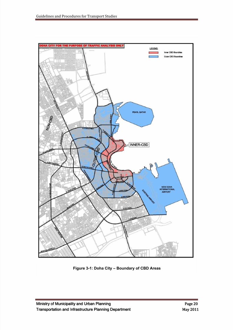
Figure 3-1 depicts the boundary of Inner CBD, Outer CBD and Non CBD Areaswithin Doha City. Consultants shall be advised that:
a) This figure is for the purpose of undertaking transport studies and is not theactual CBD boundaries.
b) The Department of Transportation and Infrastructure Planning, of MMUP, canadjust these boundaries without prior notice.
c) The Department of Transportation and Infrastructure Planning, of MMUP, canimpose different requirements, other than stated in this document, ondevelopments/ projects within certain area.
d) The Department of Transportation and Infrastructure Planning, of MMUP, canimpose the requirements of other area on certain developments/ projects ifseems necessary.
3.2.2 Project/ Development Description
The Consultant shall provide detail description of the proposed development/ project
and outline the major components of the project. The Consultant shall highlight anyspecific issue that the proposed project shall address/ be known to MMUP or anyspecific requirement that the proposed project have to meet.
a) Project‘s size, length, area, etc.
b) Project‘s commencement and completion dates.
c) Project‘s owner(s) names and their contact details.
d) Consultants involved in the design/ management and their contact details.
e) Main Contractor and his contact details.
f) Names of MMUP staff involve in reviewing the project application and design
8/9/2019 TIPD Qatar Traffic Manual & Guidelines
http://slidepdf.com/reader/full/tipd-qatar-traffic-manual-guidelines 29/197
Guidelines and Procedures for Transport Studies
MMiinniissttr r yy oof f MMuunniicciippaalliittyy aanndd UUr r bbaann PPllaannnniinngg PPaaggee 2200
TTr r aannssppoor r ttaattiioonn aanndd IInnf f r r aassttr r uuccttuur r ee PPllaannnniinngg DDeeppaar r ttmmeenntt MMaayy 22001111
Figure 3-1: Doha City – Boundary of CBD Areas
8/9/2019 TIPD Qatar Traffic Manual & Guidelines
http://slidepdf.com/reader/full/tipd-qatar-traffic-manual-guidelines 30/197
Guidelines and Procedures for Transport Studies
MMiinniissttr r yy oof f MMuunniicciippaalliittyy aanndd UUr r bbaann PPllaannnniinngg PPaaggee 2211
TTr r aannssppoor r ttaattiioonn aanndd IInnf f r r aassttr r uuccttuur r ee PPllaannnniinngg DDeeppaar r ttmmeenntt MMaayy 22001111
3.2.3 Transport Study Team
The methodology shall list and provide details of the proposed team who will beundertaking the transport study. Brief CV (no more than two pages) shall be providedas an appendix within the submitted methodology. The following professional
personnel shall be provided as a minimum:
a) Project Manager
b) Senior Traffic/ Transport Engineer
c) Traffic/ Transport Engineer or Planner
d) Senior Road Engineer
e) Urban Designer, if required
f) Infrastructure/ Utilities Engineer, if required
g) Transport Study Reviewer
3.2.4 Parking Generation Rates
The rates contained in the Dubai, United Arab Emirates (UAE), Trip Generation andParking Rates Manual, latest edition, shall be used to determine the expected totalparking generation by the proposed development. The parameters used to determinethe parking generation shall be reviewed and approved by MMUP first.
The project parking generation shall be determined based upon the gross projecttraffic (no reductions for internal or pass-by capture, if they are applicable).
The Consultant can either develop site specific rates based on similar developments/projects in Qatar or use other international parking rates, subject to MMUP approval.
3.2.5 Trip Generation Rates
The rates contained in the Dubai, United Arab Emirates (UAE), Trip Generation andParking Rates Manual, latest edition, shall be used to determine the existing (asappropriate) and total project trips expected to be generated by the proposeddevelopment. The parameters and land-use used to determine the trip generationshall be reviewed and approved by MMUP prior to using them to determine the trip
generation.
Internal capture and pass-by capture trips shall be considered based uponengineering judgment and Dubai Trip Generation and Parking Manual or the mostrecent Institute of Transportation Engineers (ITE) Trip Generation Handbook. Pass-by capture shall not exceed ten percent (10%) of the adjacent roadway volumes.
Modal split could be considered if it is appropriate, justified and agreed upon withMMUP.
The Consultant can either develop site specific rates based on similar developments/projects in Qatar or use other international trip generation rates, subject to MMUPapproval.
8/9/2019 TIPD Qatar Traffic Manual & Guidelines
http://slidepdf.com/reader/full/tipd-qatar-traffic-manual-guidelines 31/197
Guidelines and Procedures for Transport Studies
MMiinniissttr r yy oof f MMuunniicciippaalliittyy aanndd UUr r bbaann PPllaannnniinngg PPaaggee 2222
TTr r aannssppoor r ttaattiioonn aanndd IInnf f r r aassttr r uuccttuur r ee PPllaannnniinngg DDeeppaar r ttmmeenntt MMaayy 22001111
3.2.6 Sub-Area Model
MMUP will provide the Consultant with the latest update of the Qatar VISUMstrategic transport model. The Consultant shall use this strategic transport model forthe initial traffic analysis and assessment of the impact of the proposeddevelopment/project on intersections and road network in future years.
The Consultant shall suggest a sub-area model based on MMUP requirements andengineering judgment with the consultation and agreement with MMUP. The sub-area model shall be selected as a cordon that includes the proposeddevelopment/project and an appropriate road network affected by the trafficgenerated by the development or are necessary for trip generation and distribution.
The objectives of developing sub-area model are to:
Ensure the affects of the proposed development/project are properly assignedand reviewed by containing the model changes, modifications and updateswithin a smaller area
Minimize model noises
Build a robust model
Update a limited area with the latest land-use, if they are different from theTMPQ model
Update a limited area with the existing or proposed road network, if they aredifferent from the TMPQ model
Enhance the model network by adding or modifying links and intersections
Calibrate and validate a limited area using the latest land-use and traffic data
Extract matrices and traffic volumes for further analysis
In case the Transport Study includes several projects or developments, a single sub-area model shall be created to include all projects/developments within closeproximity to each other.
Detailed requirements and guidelines on the development of traffic model areprovided in other sections of this document.
All strategic modeling work shall be conducted in the entire model prior to generatingthe sub-area cordoned model for the micro-simulation usage.
3.2.7 Surrounding Area Conditions
The Consultant is required to undertake site visits to the project site and thesurrounding areas and road network to familiarize themselves with site existingconditions and proposed developments and projects within the study area. TheConsultant shall provide detailed description of the existing conditions as stated inthis guidelines document.
3.2.7.1 Existing Condition
The data collection of the existing conditions shall cover but not limited to thefollowing:
a. Site characteristics including the site location, boundaries and anticipatedarea of influence;
8/9/2019 TIPD Qatar Traffic Manual & Guidelines
http://slidepdf.com/reader/full/tipd-qatar-traffic-manual-guidelines 32/197
Guidelines and Procedures for Transport Studies
MMiinniissttr r yy oof f MMuunniicciippaalliittyy aanndd UUr r bbaann PPllaannnniinngg PPaaggee 2233
TTr r aannssppoor r ttaattiioonn aanndd IInnf f r r aassttr r uuccttuur r ee PPllaannnniinngg DDeeppaar r ttmmeenntt MMaayy 22001111
b. Existing Transportation System including transportation network, transitservice data (if any), pedestrian, bicycle and transit routes (if any),planned and programmed transportation improvements, and traffic controlmeasures;
c. Existing Transportation Demand Data; and
d. Land Use data.
3.2.7.2 Future Projects/ Developments
The data collection of the expected improvements shall cover but not limitedto the following:
a. Proposed and approved roadway improvements;
b. Planned and programmed transportation improvements and transportsystems; and
c. Planned and approved developments.
3.2.8 Study Area
The study area is the area where a detailed traffic analysis shall be conducted usingone or more of the approved traffic engineering or micro-simulation softwarepackages.
The study area shall be divided for each project into two categories, a primary studyarea and a secondary study area.
Primary Study Area: The area that will be assessed and simulated using VISSIMmicro-simulation software. This area shall include at a minimum the project
driveways and internal circulation in addition to the immediate corridors andintersections adjacent to the development.
Secondary Study Area: The area that will be assessed using Synchro, Sidra andHCS software. This area will be determined based an initial run of the most recentversion of the TMPQ VISUM Model. The area will be based on the traffic impactgenerated from the development which is equal to or more than 10% of the roadwaysservice capacities as included in the VISUM TMPQ Model.
The study area shall include at a minimum all roadway segments and intersectionsdirectly adjacent to the proposed development, as well as any other roadways andintersections that are affected by the development or the Ministry of Municipality and
Urban Planning (MMUP) considers appropriate to add to the study area as agreedupon with the Applicant at the prestart meeting. In addition, all existing drivewaysadjacent to the proposed development shall be considered as appropriate.
The extent of each study area must be sufficient to cover that part of the roadnetwork that experiences a significant impact as a result of the land use and/orhighway schemes proposals. In general, study areas are established based on thefollowing:
Existing traffic conditions;
Type and scale of the proposed development/ highway scheme; and
Future traffic conditions that may be experienced.
8/9/2019 TIPD Qatar Traffic Manual & Guidelines
http://slidepdf.com/reader/full/tipd-qatar-traffic-manual-guidelines 33/197
Guidelines and Procedures for Transport Studies
MMiinniissttr r yy oof f MMuunniicciippaalliittyy aanndd UUr r bbaann PPllaannnniinngg PPaaggee 2244
TTr r aannssppoor r ttaattiioonn aanndd IInnf f r r aassttr r uuccttuur r ee PPllaannnniinngg DDeeppaar r ttmmeenntt MMaayy 22001111
For the internal links and intersections, the carriageway links are to be presented andincluded in the transport sub-model. In effect, this means any link with a 20m right ofway or wider. In addition, there are two further criteria that will lead to a link orintersection being assessed. These are:
a. any link whose traffic flow exceeds 500 vehicles per hour, as a two-way flow,
(one-way roads 300 vehicles per hour) ; and
b. any intersection whose approach traffic from all directions totals 800 vehiclesper hour or more.
Where the scheme limit of works is located mid-block between intersections, the nextmajor intersection shall also be included within the assessment. If the intersectionalready exists and has not been recently improved, then a schematic design shall beprepared, included within the model and assessed. However, if the intersection hasbeen recently upgraded or has a design proposal, then that will be included within themodel and the operation assessed. Where necessary, the Consultant shall suggestschematic design for improvements to ensure appropriate intersection operation.
3.2.9 Traffic Assessment Methodology
The Consultant shall provide details on the proposed traffic assessment methodologyfor undertaking the proposed project/development including the following as aminimum:
1. Data collection and surveys
2. Strategic model works
3. Traffic analysis works
4. Assessment of pedestrian, cyclist and public transport
The strategic model of the Transportation Master Plan for Qatar (TMPQ) shall beused to quantify the wide impact of the proposed schemes of the development on theroad under study and adjacent road network. The detailed intersection analyses shallbe undertaken using VISSIM, SYNCHRO, TRANSYT 7F, SIDRA, and the HighwayCapacity Software (HCS). The data to feed the latter shall be taken from the TMPQstrategic model after it has been refined using the methodology outlined in VISUMModeling section, Section 6.
The Consultant shall use the TMPQ VISUM models and approved traffic softwarepackages to develop and assess their proposed options. The assessment should becarried out for the opening year and all design years (i.e. 2011, 2016, 2021 and2026). VISSIM micro-simulation model shall be built for the Primary Study Area.
3.2.10 Road safety Audit methodology
The Consultant shall submit a methodology for undertaking Road Safety Audit (RSA)for the proposed development/ project. The methodology shall identify the following:
a) The scope of audit works
b) The boundary and limits of audit works
c) The names and CVs of the audit team
8/9/2019 TIPD Qatar Traffic Manual & Guidelines
http://slidepdf.com/reader/full/tipd-qatar-traffic-manual-guidelines 34/197
Guidelines and Procedures for Transport Studies
MMiinniissttr r yy oof f MMuunniicciippaalliittyy aanndd UUr r bbaann PPllaannnniinngg PPaaggee 2255
TTr r aannssppoor r ttaattiioonn aanndd IInnf f r r aassttr r uuccttuur r ee PPllaannnniinngg DDeeppaar r ttmmeenntt MMaayy 22001111
3.3 Review Period
The estimated MMUP's technical review time is ten (10) working days, where extratime would be required according to the project size.
In case the Methodology Report is returned as not approved, the Consultant shallsubmit a revised Methodology Report within two weeks.
3.4 Deliverables
The consultant shall submit two copies of the Methodology Report for review andapproval by the Transportation and Infrastructure Planning Department.
8/9/2019 TIPD Qatar Traffic Manual & Guidelines
http://slidepdf.com/reader/full/tipd-qatar-traffic-manual-guidelines 35/197
Guidelines and Procedures for Transport Studies
MMiinniissttr r yy oof f MMuunniicciippaalliittyy aanndd UUr r bbaann PPllaannnniinngg PPaaggee 2266
TTr r aannssppoor r ttaattiioonn aanndd IInnf f r r aassttr r uuccttuur r ee PPllaannnniinngg DDeeppaar r ttmmeenntt MMaayy 22001111
4 DEVELOPMENT/ PROJECT PLANS AND REPORTS
4.1 Overview
The Consultant shall submit to the Transportation and Infrastructure PlanningDepartment of MMUP the project and development plans along with the developmentreview report. The plans and drawings shall be based on MMUP Concept DesignSubmittal and Review Guidelines.
4.2 Developm ent Plans
The Consultant shall submit, attached to the report, copies of the proposeddevelopment plans and design drawings for review and acceptance. These plans anddrawings shall be based on MMUP Concept Design Submittal and ReviewGuidelines.
The plans and drawings shall be submitted in A3 size if inserted and referenced inthe report, and in A1 or A0 if attached to the appendices. All plans/ drawings shall besigned and to an appropriate engineering scale.
The plans shall include but not limited to the following:
Development plans including location of buildings and their entrances.
Road layout drawings.
Pedestrians and cyclists plans and strategies.
Parking layout plans.
Locations of accesses (entries and exits).
Public transport plans.
Road Signs and pavement marking drawings.
Traffic signals plans.
ITS plans and strategies.
Traffic management strategies and plans.
4.3 Site Ac cess and Traff ic Circu lation
A review of the on-site and off-site circulation of the traffic generated from and withinthe development shall be studied and recommendations shall be made. Sitecirculation should be designed in such a way as to minimize the required number ofaccesses. Internal circulation roadways should provide safe, smooth and efficientcirculation of site traffic to and from:
1. Accesses
2. Buildings
3. Parking areas
4. Pick-up/drop-off points (including transit)
5. Service and loading areas
8/9/2019 TIPD Qatar Traffic Manual & Guidelines
http://slidepdf.com/reader/full/tipd-qatar-traffic-manual-guidelines 36/197
Guidelines and Procedures for Transport Studies
MMiinniissttr r yy oof f MMuunniicciippaalliittyy aanndd UUr r bbaann PPllaannnniinngg PPaaggee 2277
TTr r aannssppoor r ttaattiioonn aanndd IInnf f r r aassttr r uuccttuur r ee PPllaannnniinngg DDeeppaar r ttmmeenntt MMaayy 22001111
In addition, circulation for the proposed project shall be evaluated in regards todriveway(s) location and their proximity to:
Adjacent Streets;
Adjacent developments driveways;
Service roads entrances and exits;
Major developments;
Signalized and un-signalized intersections.
Then recommendations shall be made to resolve any conflicts.
An analysis shall be conducted evaluating the internal and external roadwaycharacteristics and the appropriate queue necessary at the driveways andintersections to accommodate future traffic.
The on-site planning and design for the internal circulation should consider elementslike:
1. Horizontal and vertical alignments
2. Pavement marking and signing
3. Paving delineation (materials and finishes) of all pedestrian areas includingwalkways and plazas.
4. Sight distance
5. Taxi drop-off and pick-up areas
6. Emergency vehicle access7. Drop-off and pick-up areas
8. Design vehicle turning movements and storage
9. Internal intersection control, channelization and main aisle location
10. Public transit
11. Pedestrian and cyclist movement
12. Site furnishings (lighting, bollards, benches)
13. Speed control
14. Garbage bins and how they are accessed15. Surveillance from adjacent buildings to discourage crime and vandalism.
4.4 Car Parking
The car parking design, circulation and analysis shall be as per the followingClauses:
4.4.1 Parking Design
The car parking design shall be as per TMPQ Parking Design Guidelines and QatarHighway Design Manual (QHDM), latest revisions.
8/9/2019 TIPD Qatar Traffic Manual & Guidelines
http://slidepdf.com/reader/full/tipd-qatar-traffic-manual-guidelines 37/197
Guidelines and Procedures for Transport Studies
MMiinniissttr r yy oof f MMuunniicciippaalliittyy aanndd UUr r bbaann PPllaannnniinngg PPaaggee 2288
TTr r aannssppoor r ttaattiioonn aanndd IInnf f r r aassttr r uuccttuur r ee PPllaannnniinngg DDeeppaar r ttmmeenntt MMaayy 22001111
4.4.2 Parking Circulation
The Consultant shall conduct a Parking Circulation Review for the proposed parkinggarage and surface lot. The consultant shall coordinate with the Ministry ofMunicipality and Urban Planning (MMUP), Transportation and Infrastructure PlanningDepartment, regarding the traffic circulation review. The Consultant shall assess andreview the following items at a minimum and make recommendations to mitigate anydeficiencies:
1. Number of access;
2. Access locations;
3. Access dimensions;
4. Internal and External Traffic Circulation;
5. Turning radius for the driveways, aisles, and turning corners, using AutoTURN software and using an SUV as a design vehicle;
6. Disabled parking location and number;7. Pedestrian circulation and safe paths ;
8. Bicycle access / circulation;
9. Bicycle racks location;
10. Sight distance assessment at driveway(s) locations and turning corners;
11. Potential conflicts with major streets or parking connecting to the parkinggarage or surface lot;
12. Delivery vehicles location and their ability to park to load and unload using ata minimum 10 meter truck turning template;
13. Shopping trolleys location;
14. Drop off area location, if any;
15. Taxi area accesses and queue distance; and
16. Bus access and drop off.
A truck turning template shall be provided showing how trucks will be able to get inand out of the development to load and unload as well as how trucks will be able tonavigate the study area intersections.
4.4.3 Parking Analysis
The number of parking spaces provided shall be compared to the required parkingusing parking generation rates for Qatar, or Dubai Manual, if there are no parkingrates for Qatar. Any deficiencies in the number of parking spaces required shall bemitigated in a satisfactory manner acceptable to MMUP.
4.5 Pedestrian
Pedestrian path, facilities, analysis and design shall be considered and addressed inthe Development/Project plans and report.
The Consultant shall review and refer to the reference materials listed in Section 1.7,
especially the TMPQ Pedestrian Design Guidelines. Reference to other internationalmanuals and standards can be made.
8/9/2019 TIPD Qatar Traffic Manual & Guidelines
http://slidepdf.com/reader/full/tipd-qatar-traffic-manual-guidelines 38/197
Guidelines and Procedures for Transport Studies
MMiinniissttr r yy oof f MMuunniicciippaalliittyy aanndd UUr r bbaann PPllaannnniinngg PPaaggee 2299
TTr r aannssppoor r ttaattiioonn aanndd IInnf f r r aassttr r uuccttuur r ee PPllaannnniinngg DDeeppaar r ttmmeenntt MMaayy 22001111
4.6 Bicycle
Bicycle path, facilities, analysis and design shall be considered and addressed in theDevelopment/Project plans and report.
The Consultant shall review and refer to the reference materials listed in Section 1.7,
especially the TMPQ Bicycle Design Guidelines. Reference to other internationalmanuals and standards can be made.
4.7 Publ ic Transport
Public Transport such as Buses, Metro, LRT, Tram, etc. shall be considered andaddressed in the Development/Project plans and report. Facilities for andaccessibilities to Public Transport shall analyzed and detailed in the plans andreports.
The Consultant shall review and refer to the reference materials listed in Section 1.7.Reference to other international manuals and standards can be made.
4.8 On-Site Planning and Parking Princip les
An integral part of an overall transport study relates to basic site planning principles.It is extremely important that off-site roadway improvements be fully integrated withon-site recommendations. This section includes: approach to site planning and on-site planning principles (access points, vehicular queuing storage, internal circulation,speed control, service vehicles and drives, signs and markings, parking, non-motorized facilities and accessible facilities).
4.8.1 Approach to Site PlanningInternal design will have a direct bearing on the adequacy of site access points. Theidentification of access points between the site and the external roadway system, andsubsequent recommendations concerning the design of those access points, isdirectly related to both the directional distribution of site traffic and the internalcirculation system configuration.
It is clear that driveway traffic volumes of varying sizes need to be accommodatedon-site, in terms of both providing sufficient capacity and queuing space and ofdistributing automobiles to and from parking spaces, pick-up/drop-off points anddrive-through lanes. An integrated system should deliver vehicles from the externalroadway system in a manner easily understood by typical drivers and that maximizes
efficiency, accommodates anticipated traffic patterns and ensures public safety.Pedestrian linkages should conveniently and safely connect bus stops and parkingfacilities with building entrances as well as other key origins and destinations wherepossible. Similar linkages should be provided between buildings.
The design and operation of driveways are influenced by:
1. Type of adjoining land use,
2. Dimensions of the property,
3. Trip generation characteristics of the site design vehicle(s),
4. Type of highway which the driveway abuts, and
5. Neighboring driveways and driveways on opposite side of roadway.
8/9/2019 TIPD Qatar Traffic Manual & Guidelines
http://slidepdf.com/reader/full/tipd-qatar-traffic-manual-guidelines 39/197
Guidelines and Procedures for Transport Studies
MMiinniissttr r yy oof f MMuunniicciippaalliittyy aanndd UUr r bbaann PPllaannnniinngg PPaaggee 3300
TTr r aannssppoor r ttaattiioonn aanndd IInnf f r r aassttr r uuccttuur r ee PPllaannnniinngg DDeeppaar r ttmmeenntt MMaayy 22001111
4.8.2 Driveway Location
Important principles for the location of the driveways include:
Access shall be directed, as much as possible, to side streets or the supported roadsystem. Even when there is direct access, side street access can help relieve
pressure on the main road and provide less congested alternatives to the driver.
Driveways shall be located as far from intersections as possible, especially if thespacing standards in the access management standards cannot be met.
Driveways shall be located away from the functional area of the intersection.
4.8.3 Review of Driveways Access Plans
Development of the site plan should also be based upon sound access managementprinciples. The site plan should be developed in sufficient detail to allow the MMUPstaff to clearly confirm the following:
1. Site's internal circulation system should allow for all vehicular and non-vehicular circulation to take place on-site and not spill onto adjacentstreets at any time;
2. Angle of driveways should be conducive to safe and efficient entry toand exit from the site. One-way driveways shall operate as intendedand designed not to cause confusion;
3. Driveway width and radii should be sufficient to accommodate allexpected types of vehicles, volumes and operating speeds, includingemergency vehicles (per state and/or local design guidelines);
4. Driveway grade should provide for entry and exit at a safe speed;
5. Sight distance should be sufficient for safe and efficient entry and exit;
6. Driveway locations should be adequately spaced in relation to eachother, off-site driveways, adjacent major intersections and nearbyproperty lines to allow safe and efficient operations;
7. Total number of driveways should be sufficient to handle expectedvolumes at adequate levels of service, without having too many
driveways;
8. Potential auxiliary and acceleration/deceleration lanes should beconsidered on the main roadway, if there is a demonstrated need forsuch to improve operations on both the main road and the access
driveways; and
9. Main street operations should be minimally impacted by the site'sdriveway design, proposed traffic control and location.
The site plan review also should include the following steps:
1. Identify entrance and exit locations, required lanes and requiredqueuing distances;
2. Identify internal roadway circulation systems to carry motor vehicles,bicycles and pedestrians between access points and parking areas,pick-up/drop-off points and drive-through lanes;
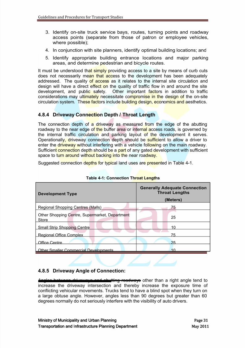
8/9/2019 TIPD Qatar Traffic Manual & Guidelines
http://slidepdf.com/reader/full/tipd-qatar-traffic-manual-guidelines 40/197
Guidelines and Procedures for Transport Studies
MMiinniissttr r yy oof f MMuunniicciippaalliittyy aanndd UUr r bbaann PPllaannnniinngg PPaaggee 3311
TTr r aannssppoor r ttaattiioonn aanndd IInnf f r r aassttr r uuccttuur r ee PPllaannnniinngg DDeeppaar r ttmmeenntt MMaayy 22001111
3. Identify on-site truck service bays, routes, turning points and roadwayaccess points (separate from those of patron or employee vehicles,where possible);
4. In conjunction with site planners, identify optimal building locations; and
5. Identify appropriate building entrance locations and major parkingareas, and determine pedestrian and bicycle routes.
It must be understood that simply providing access to a site by means of curb cutsdoes not necessarily mean that access to the development has been adequatelyaddressed. The quality of access as it relates to the internal site circulation anddesign will have a direct effect on the quality of traffic flow in and around the sitedevelopment, and public safety. Other important factors in addition to trafficconsiderations may ultimately necessitate compromise in the design of the on-sitecirculation system. These factors include building design, economics and aesthetics.
4.8.4 Driveway Connection Depth / Throat Length
The connection depth of a driveway as measured from the edge of the abuttingroadway to the near edge of the buffer area or internal access roads, is governed bythe internal traffic circulation and parking layout of the development it serves.Operationally, driveway connection depth should be sufficient to allow a driver toenter the driveway without interfering with a vehicle following on the main roadway.Sufficient connection depth should be a part of any gated development with sufficientspace to turn around without backing into the near roadway.
Suggested connection depths for typical land uses are presented in Table 4-1.
Table 4-1: Connection Throat Lengths
Development Type
Generally Adequate ConnectionThroat Lengths
(Meters)
Regional Shopping Centres (Malls) 75
Other Shopping Centre, Supermarket, Department
Store25
Small Strip Shopping Centre 10
Regional Office Complex 75
Office Centre 25Other Smaller Commercial Developments 10
4.8.5 Driveway Angle of Connection:
Angles between driveways and abutting roadways other than a right angle tend toincrease the driveway intersection and thereby increase the exposure time ofconflicting vehicular movements. Trucks tend to have a blind spot when they turn ona large obtuse angle. However, angles less than 90 degrees but greater than 60degrees normally do not seriously interfere with the visibility of auto drivers.
8/9/2019 TIPD Qatar Traffic Manual & Guidelines
http://slidepdf.com/reader/full/tipd-qatar-traffic-manual-guidelines 41/197
Guidelines and Procedures for Transport Studies
MMiinniissttr r yy oof f MMuunniicciippaalliittyy aanndd UUr r bbaann PPllaannnniinngg PPaaggee 3322
TTr r aannssppoor r ttaattiioonn aanndd IInnf f r r aassttr r uuccttuur r ee PPllaannnniinngg DDeeppaar r ttmmeenntt MMaayy 22001111
Therefore, connection angles at the intersection of two-way driveways with two-wayroadways having unrestricted turning movements should be set at, or as close aspractical to, 90 degrees. However, a pair of two-way driveways or a pair of one-waydriveways with limited turning maneuvers may be set at connection angles less than90 degrees since the number of conflict points will be reduced and the right turningspeed will be increased.
4.8.6 On-Site Principles of Access Points
Best practices recognize that access points are intersections and should be designedwith the same perspective given legs of any other intersection having similarcharacteristics and volumes. The number of lanes, adequate storage, appropriatesigning and striping and provision for pedestrian interaction are all elements thatshould be fully consistent with best practice requirements for off-site roadwayintersection links.
The sharing of a driveway access point by two or more developments is desirableparticularly where property frontages are short and driveway volumes will be low.These driveways should be located on joint property lines or be accessible via crossaccess easements on the private property being served by the joint driveway.
The criteria used for on-site roadways must be the same as that used for off-siteroadways. Today‘s driver has been conditioned by consistent regulatory signing, aswell as by rationally adopted signing/striping criteria. The criteria behind the signsand markings that drivers are accustomed to on public roadway systems should bereinforced at entrances and exits of private developments.
Site access points should be located and designed in accordance with the guidelinesin Table 4-2.
Table 4-2 : Site Access Point Guidelines
Step Action Comment
1 Adequate spacing should be
maintained from adjacent
street and driveway
intersections
Distances between driveways and adjacent
street intersections should be sufficient to
minimize driveway blockage by queues from
those intersections and from inbound left-turn
lanes back to the intersections
2 If the driveway is proposed to
be signalized, it should be
located to facilitate traffic
progression past the site
A signal progression analysis may be warranted
in such situations
3 Access driveways should
intercept traffic approaching
the site as efficiently as
possible
4 Adequate inbound and
outbound capacity should be
provided in proportion to the
distribution of site traffic
The number of driveways should be compatible
with site access capacity needs and should
minimize adverse impacts on adjacent roads. A
capacity analysis, gap check, or lane adequacy
check should be conducted for each driveway.
Joint access should be considered, especially
where several adjacent properties have relativelyshort frontages (45 metres or less on arterials)
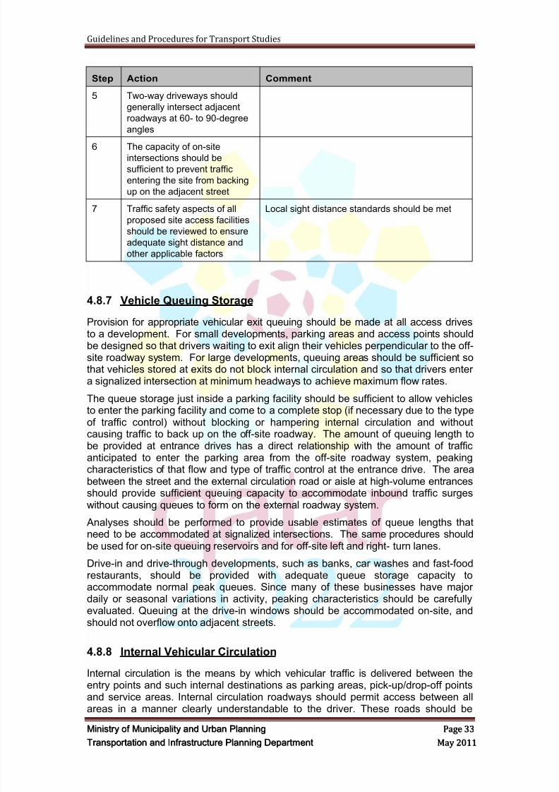
8/9/2019 TIPD Qatar Traffic Manual & Guidelines
http://slidepdf.com/reader/full/tipd-qatar-traffic-manual-guidelines 42/197
Guidelines and Procedures for Transport Studies
MMiinniissttr r yy oof f MMuunniicciippaalliittyy aanndd UUr r bbaann PPllaannnniinngg PPaaggee 3333
TTr r aannssppoor r ttaattiioonn aanndd IInnf f r r aassttr r uuccttuur r ee PPllaannnniinngg DDeeppaar r ttmmeenntt MMaayy 22001111
Step Action Comment
5 Two-way driveways should
generally intersect adjacent
roadways at 60- to 90-degree
angles
6 The capacity of on-site
intersections should be
sufficient to prevent traffic
entering the site from backing
up on the adjacent street
7 Traffic safety aspects of all
proposed site access facilities
should be reviewed to ensure
adequate sight distance and
other applicable factors
Local sight distance standards should be met
4.8.7 Vehicle Queuing Storage
Provision for appropriate vehicular exit queuing should be made at all access drivesto a development. For small developments, parking areas and access points shouldbe designed so that drivers waiting to exit align their vehicles perpendicular to the off-site roadway system. For large developments, queuing areas should be sufficient sothat vehicles stored at exits do not block internal circulation and so that drivers entera signalized intersection at minimum headways to achieve maximum flow rates.
The queue storage just inside a parking facility should be sufficient to allow vehiclesto enter the parking facility and come to a complete stop (if necessary due to the typeof traffic control) without blocking or hampering internal circulation and withoutcausing traffic to back up on the off-site roadway. The amount of queuing length tobe provided at entrance drives has a direct relationship with the amount of trafficanticipated to enter the parking area from the off-site roadway system, peakingcharacteristics of that flow and type of traffic control at the entrance drive. The areabetween the street and the external circulation road or aisle at high-volume entrancesshould provide sufficient queuing capacity to accommodate inbound traffic surgeswithout causing queues to form on the external roadway system.
Analyses should be performed to provide usable estimates of queue lengths thatneed to be accommodated at signalized intersections. The same procedures shouldbe used for on-site queuing reservoirs and for off-site left and right- turn lanes.
Drive-in and drive-through developments, such as banks, car washes and fast-foodrestaurants, should be provided with adequate queue storage capacity toaccommodate normal peak queues. Since many of these businesses have majordaily or seasonal variations in activity, peaking characteristics should be carefullyevaluated. Queuing at the drive-in windows should be accommodated on-site, andshould not overflow onto adjacent streets.
4.8.8 Internal Vehicular Circulation
Internal circulation is the means by which vehicular traffic is delivered between theentry points and such internal destinations as parking areas, pick-up/drop-off points
and service areas. Internal circulation roadways should permit access between allareas in a manner clearly understandable to the driver. These roads should be
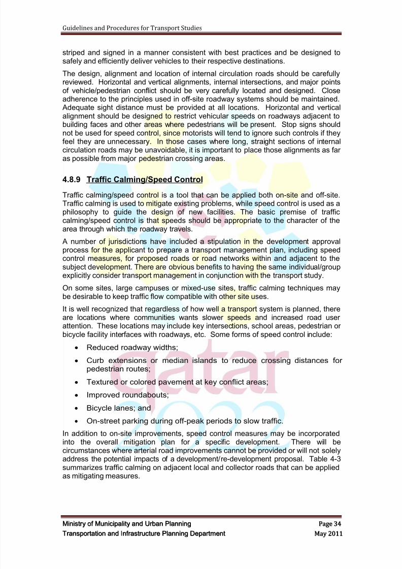
8/9/2019 TIPD Qatar Traffic Manual & Guidelines
http://slidepdf.com/reader/full/tipd-qatar-traffic-manual-guidelines 43/197
Guidelines and Procedures for Transport Studies
MMiinniissttr r yy oof f MMuunniicciippaalliittyy aanndd UUr r bbaann PPllaannnniinngg PPaaggee 3344
TTr r aannssppoor r ttaattiioonn aanndd IInnf f r r aassttr r uuccttuur r ee PPllaannnniinngg DDeeppaar r ttmmeenntt MMaayy 22001111
striped and signed in a manner consistent with best practices and be designed tosafely and efficiently deliver vehicles to their respective destinations.
The design, alignment and location of internal circulation roads should be carefullyreviewed. Horizontal and vertical alignments, internal intersections, and major pointsof vehicle/pedestrian conflict should be very carefully located and designed. Close
adherence to the principles used in off-site roadway systems should be maintained. Adequate sight distance must be provided at all locations. Horizontal and verticalalignment should be designed to restrict vehicular speeds on roadways adjacent tobuilding faces and other areas where pedestrians will be present. Stop signs shouldnot be used for speed control, since motorists will tend to ignore such controls if theyfeel they are unnecessary. In those cases where long, straight sections of internalcirculation roads may be unavoidable, it is important to place those alignments as faras possible from major pedestrian crossing areas.
4.8.9 Traffic Calming/Speed Control
Traffic calming/speed control is a tool that can be applied both on-site and off-site.Traffic calming is used to mitigate existing problems, while speed control is used as aphilosophy to guide the design of new facilities. The basic premise of trafficcalming/speed control is that speeds should be appropriate to the character of thearea through which the roadway travels.
A number of jurisdictions have included a stipulation in the development approvalprocess for the applicant to prepare a transport management plan, including speedcontrol measures, for proposed roads or road networks within and adjacent to thesubject development. There are obvious benefits to having the same individual/groupexplicitly consider transport management in conjunction with the transport study.
On some sites, large campuses or mixed-use sites, traffic calming techniques may
be desirable to keep traffic flow compatible with other site uses.It is well recognized that regardless of how well a transport system is planned, thereare locations where communities wants slower speeds and increased road userattention. These locations may include key intersections, school areas, pedestrian orbicycle facility interfaces with roadways, etc. Some forms of speed control include:
Reduced roadway widths;
Curb extensions or median islands to reduce crossing distances forpedestrian routes;
Textured or colored pavement at key conflict areas;
Improved roundabouts;
Bicycle lanes; and
On-street parking during off-peak periods to slow traffic.
In addition to on-site improvements, speed control measures may be incorporatedinto the overall mitigation plan for a specific development. There will becircumstances where arterial road improvements cannot be provided or will not solelyaddress the potential impacts of a development/re-development proposal. Table 4-3summarizes traffic calming on adjacent local and collector roads that can be appliedas mitigating measures.
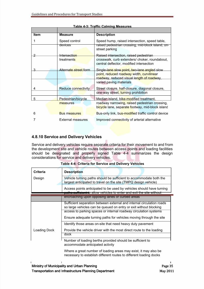
8/9/2019 TIPD Qatar Traffic Manual & Guidelines
http://slidepdf.com/reader/full/tipd-qatar-traffic-manual-guidelines 44/197
Guidelines and Procedures for Transport Studies
MMiinniissttr r yy oof f MMuunniicciippaalliittyy aanndd UUr r bbaann PPllaannnniinngg PPaaggee 3355
TTr r aannssppoor r ttaattiioonn aanndd IInnf f r r aassttr r uuccttuur r ee PPllaannnniinngg DDeeppaar r ttmmeenntt MMaayy 22001111
Table 4-3: Traffic Calming Measures
Item Measure Description
1 Speed control
devices
Speed hump, raised intersection, speed table,
raised pedestrian crossing, mid-block island, on-
street parking2 Intersection
treatments
Raised intersection, raised pedestrian
crosswalk, curb extenders/ choker, roundabout,
central deflector, modified intersection
3 Alternate street form Single-lane slow point, two-lane angled slow
point, reduced roadway width, curvilinear
roadway, reduced visual length of roadway,
varied paving materials
4 Reduce connectivity Street closure, half-closure, diagonal closure,
one-way street, turning prohibition
5 Pedestrian/bicycle
measures
Median island, bike-modified treatment,
roadway narrowing, raised pedestrian crossing,
bicycle lane, separate footway, mid-block island
6 Bus measures Bus-only link, bus-modified traffic control device
7 External measures Improved connectivity of arterial alternative
4.8.10 Service and Delivery Vehicles
Service and delivery vehicles require separate criteria for their movement to and fromthe development site and vehicle routes between access points and loading facilities
should be designated and properly signed Table 4-4 summarizes the designconsiderations for service and delivery vehicles.
Table 4-4: Criteria for Service and Delivery Vehicles
Criteria Description
Design Vehicle turning paths should be sufficient to accommodate both the
largest anticipated to travel on the site (TMPQ design vehicle)
Access points anticipated to be used by vehicles should have turning
paths sufficient to allow vehicles to enter and exit the site without
encroaching upon opposing lanes or curbed areas
Sufficient separation between external and internal circulation roadsso large vehicles can be queued on entry or exit without blocking
access to parking spaces or internal roadway circulation systems
Ensure adequate turning paths for vehicles moving through the site
Identify those areas on-site that need heavy duty pavement
Loading Dock Provide the vehicle driver with the most direct route to the loading
dock
Number of loading berths provided should be sufficient to
accommodate anticipated activity
Where a great number of loading areas may exist, it may also be
necessary to establish different routes to different loading docks
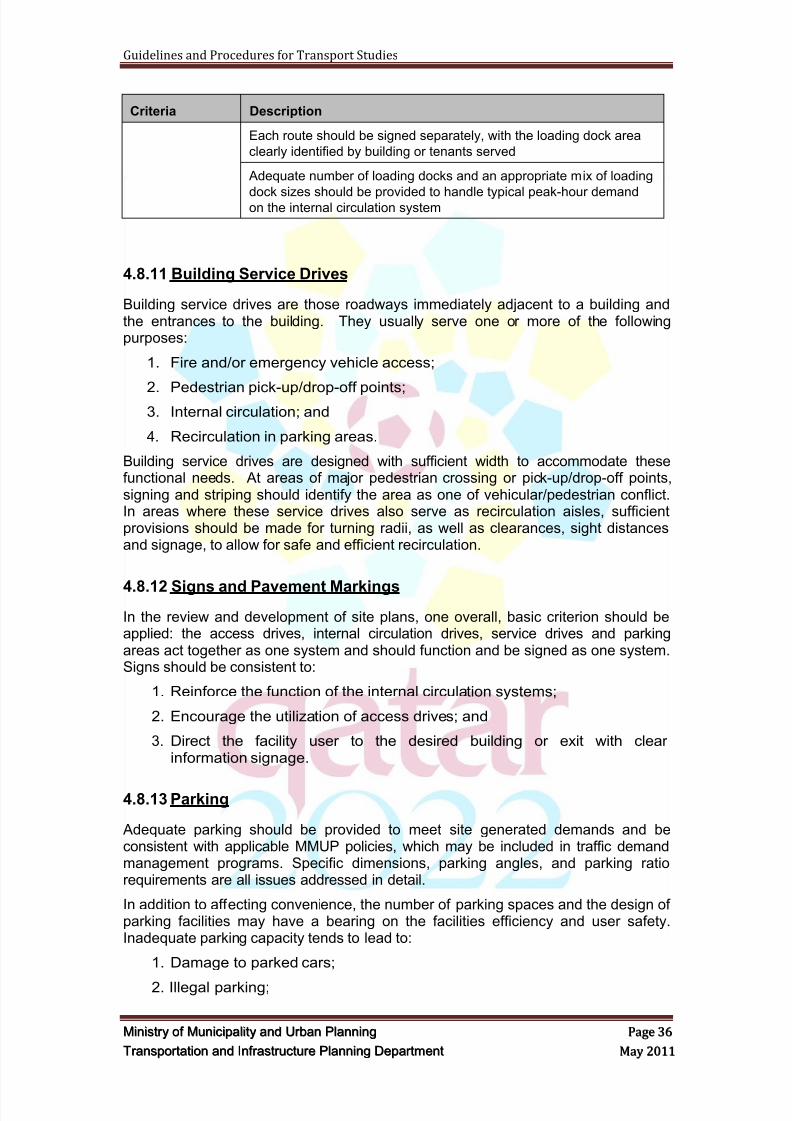
8/9/2019 TIPD Qatar Traffic Manual & Guidelines
http://slidepdf.com/reader/full/tipd-qatar-traffic-manual-guidelines 45/197
Guidelines and Procedures for Transport Studies
MMiinniissttr r yy oof f MMuunniicciippaalliittyy aanndd UUr r bbaann PPllaannnniinngg PPaaggee 3366
TTr r aannssppoor r ttaattiioonn aanndd IInnf f r r aassttr r uuccttuur r ee PPllaannnniinngg DDeeppaar r ttmmeenntt MMaayy 22001111
Criteria Description
Each route should be signed separately, with the loading dock area
clearly identified by building or tenants served
Adequate number of loading docks and an appropriate mix of loading
dock sizes should be provided to handle typical peak-hour demandon the internal circulation system
4.8.11 Building Service Drives
Building service drives are those roadways immediately adjacent to a building andthe entrances to the building. They usually serve one or more of the followingpurposes:
1. Fire and/or emergency vehicle access;
2. Pedestrian pick-up/drop-off points;3. Internal circulation; and
4. Recirculation in parking areas.
Building service drives are designed with sufficient width to accommodate thesefunctional needs. At areas of major pedestrian crossing or pick-up/drop-off points,signing and striping should identify the area as one of vehicular/pedestrian conflict.In areas where these service drives also serve as recirculation aisles, sufficientprovisions should be made for turning radii, as well as clearances, sight distancesand signage, to allow for safe and efficient recirculation.
4.8.12 Signs and Pavement Markings
In the review and development of site plans, one overall, basic criterion should beapplied: the access drives, internal circulation drives, service drives and parkingareas act together as one system and should function and be signed as one system.Signs should be consistent to:
1. Reinforce the function of the internal circulation systems;
2. Encourage the utilization of access drives; and
3. Direct the facility user to the desired building or exit with clearinformation signage.
4.8.13 Parking
Adequate parking should be provided to meet site generated demands and beconsistent with applicable MMUP policies, which may be included in traffic demandmanagement programs. Specific dimensions, parking angles, and parking ratiorequirements are all issues addressed in detail.
In addition to affecting convenience, the number of parking spaces and the design ofparking facilities may have a bearing on the facilities efficiency and user safety.Inadequate parking capacity tends to lead to:
1. Damage to parked cars;
2. Illegal parking;
8/9/2019 TIPD Qatar Traffic Manual & Guidelines
http://slidepdf.com/reader/full/tipd-qatar-traffic-manual-guidelines 46/197
Guidelines and Procedures for Transport Studies
MMiinniissttr r yy oof f MMuunniicciippaalliittyy aanndd UUr r bbaann PPllaannnniinngg PPaaggee 3377
TTr r aannssppoor r ttaattiioonn aanndd IInnf f r r aassttr r uuccttuur r ee PPllaannnniinngg DDeeppaar r ttmmeenntt MMaayy 22001111
3. Loss of customers;
4. Parking areas that could impair sight distances;
5. Decrease lane capacity; and
6. Impact internal circulation roads.
Excess parking can result in inefficient use of funds and could encourage unsafedriving practices in almost-empty parking areas. Parking quantity should thus beviewed not only within the context of what is required by local zoning ordinances, butalso in the context of how the facility itself will function.
Shared parking is a valid approach to the determination of total parking needs of anymixed-use facility, as long as parking for all uses is conveniently shared. Closebuilding proximity and efficient internal circulation systems, ramping systems andaccess drives are necessary for shared parking to be successful. A shared parkingarea must be convenient to more than one destination.
4.8.14 Pedestrian, Transit, Bicycle and Accessible FacilitiesThe overall site plans should also consider public transport, pedestrians (includingthose with mobility impairments and/or children) and bicyclists. In areas wherebicyclists are likely to use the internal circulation system, adequate facilities forbicycle parking, with appropriate pavement type and design, should be included. Appropriate public transport facilities, and shuttle bus staging areas should beaccommodated at one of the following locations:
1. Adjacent to service drive and entrance areas;
2. At key locations along circulation drives; and
3. At major pedestrian focal points along the external roadway system.
Pedestrian connections between these facilities and the site's buildings should beintegrated in the overall design of the project. Proper design of pedestrian facilitiescan reduce the use of motor vehicles for trips within a development and betweennearby developments. Handicapped access should also be provided in accordancewith international standards and best practices.
TMPQ has a parking design guideline manual that includes car park layoutrequirements, recommended parking dimensions and parking surveys.
4.8.15 Purpose and End Use
Again, the traffic and transport study is intended to assess the effects that a particulardevelopment will have on the surrounding transport network, and determine whatprovisions are needed for safe and efficient site access and traffic flow.
The final report documents the purpose, procedures, assumptions, findings,conclusions and recommendations of the study. The report provides developers withrecommendations on site selection, site transport planning and transport impacts;and assists MMUP in reviewing the attributes of the proposed development inconjunction with requests for land subdivision, zoning changes, building permits, orother development reviews, and to establish or negotiate mitigation requirementswhere off-site impacts require improvements beyond those otherwise needed. Thereport will be used by MMUP as the basis for establishing impact fees or assessingthe developer contributions to transport facility improvements.
8/9/2019 TIPD Qatar Traffic Manual & Guidelines
http://slidepdf.com/reader/full/tipd-qatar-traffic-manual-guidelines 47/197
Guidelines and Procedures for Transport Studies
MMiinniissttr r yy oof f MMuunniicciippaalliittyy aanndd UUr r bbaann PPllaannnniinngg PPaaggee 3388
TTr r aannssppoor r ttaattiioonn aanndd IInnf f r r aassttr r uuccttuur r ee PPllaannnniinngg DDeeppaar r ttmmeenntt MMaayy 22001111
4.9 Road Safety Au dit
A Road Safety Audit (RSA) shall be conducted by an independent qualified andexperienced traffic safety engineer(s). The safety analysis and audit shall beconducted for all of the intersections, road network, parking areas, driveways,
pedestrians‘, Taxi drop-off and pick-up, bus stops and cyclists‘ facilities and anyother transport facilities within the primary study area and otherroadways/intersections that mitigation measures have been recommended in theTransport Study.
A report shall be prepared, based on international guidelines and practices, by theroad safety auditor and shall include the following:
1. Risk identification
2. Risk assessment
3. Recommendations to address these risks
The methodology of the RSA shall be based on international guidelines, standardsand practices, e.g. Austroads, British and Canadian.
In case that the audit has been undertaken by a junior engineer, less than 8 years ofrelevant professional experience, the road safety audit shall be reviewed by a SeniorRoad Safety Auditor who has not been involved in conducting the audit.
The Applicant and/or his representative and the TS Consultant shall ensure that allsafety issues raised by the Auditor have been reviewed and addressed in the finaldevelopment/ project site plans.
4.10 The Project/Development Review Repor t
The consultant shall prepare and submit Project/ Development Review Report whichshall discuss, include and address the items included within Section 4. The reportshall include the following items as a minimum:
1. Project/Development description
2. Internal traffic circulation
3. External traffic circulation
4. Parking
5. Access points (entrances and exits)
6. Swept path analyses
7. Initial Road Safety Audit
The Project/ Development Report shall be reviewed by either a SeniorTraffic/Transport Engineer or the Manager of the Transportation Section/Departmentof the Firm who has not been involved in preparing/writing the report.
4.11 Review Period
The estimated MMUP's technical review time is 15 working days, where extra timewould be required according to the project size.
8/9/2019 TIPD Qatar Traffic Manual & Guidelines
http://slidepdf.com/reader/full/tipd-qatar-traffic-manual-guidelines 48/197
Guidelines and Procedures for Transport Studies
MMiinniissttr r yy oof f MMuunniicciippaalliittyy aanndd UUr r bbaann PPllaannnniinngg PPaaggee 3399
TTr r aannssppoor r ttaattiioonn aanndd IInnf f r r aassttr r uuccttuur r ee PPllaannnniinngg DDeeppaar r ttmmeenntt MMaayy 22001111
In case the Project/ Development Review Report and plans are returned as notapproved, the Consultant shall submit the revised report and plans within two weeks.
4.12 Deliverables
The Consultant shall submit the following:
The PRELIMINARY Development Plans, two hard copies – A0 size.
The Project/ Development Review Report, two hard copies.
The Project/ Development Review Report, one digital copy.
The FINAL Development Plans, two hard copies – A0 size.
The FINAL Development Plans, two digital copies
8/9/2019 TIPD Qatar Traffic Manual & Guidelines
http://slidepdf.com/reader/full/tipd-qatar-traffic-manual-guidelines 49/197
Guidelines and Procedures for Transport Studies
MMiinniissttr r yy oof f MMuunniicciippaalliittyy aanndd UUr r bbaann PPllaannnniinngg PPaaggee 4400
TTr r aannssppoor r ttaattiioonn aanndd IInnf f r r aassttr r uuccttuur r ee PPllaannnniinngg DDeeppaar r ttmmeenntt MMaayy 22001111
5 TRAFFIC SURVEYS AND DATA COLLECTION
5.1 Overview
The Consultant shall conduct the traffic surveys and data collections as specified inthis section. The Consultant shall submit the traffic surveys data and analysis as aseparate report after the completion of these surveys and prior to the commission oftraffic analysis and preparation of TS report. The presentation format of the trafficsurveys shall be submitted to MMUP for acceptance.
Traffic counts and surveys data that are less than 12 months can be used in thetransport study, if agreed with MMUP. If counts are not available or older than 12months, then new counts need to be undertaken. In addition, data shall be collectedand observations shall be made with regards to public transport, pedestrian andbicycle activities.
5.2 Data Col lection of Existin g Roads
The Consultant shall collect all the required and available information and data of theexisting conditions and road network to undertake the required analysis works andprepare the required studies, reports and plans. The information and data collectedshall include the following as a minimum:
1. Site reconnaissance of the surrounding road network
2. Topographical survey of adjacent and affected road network
3. As-built drawings of roads
4. Existing topographical surveys
5. Previous traffic studies
6. Existing service utilities
7. Existing public transport services and facilities
8. Existing pedestrian and cyclist paths and facilities
The assembly of available data should be accompanied by a detailedreconnaissance of the project site, area roadways and surrounding vicinity. Thisshould include recording all relevant characteristics needed for the analysis, plus
observations of existing traffic conditions. If the person overseeing the analysis is notthe person collecting the field data, then that individual should also undertakepersonal observations of the key intersections and roadway segments, plusobservations of existing traffic conditions.
Current data should also be collected as necessary to supplement informationalready available. Unless there are locally preferred criteria to the contrary, trafficvolume data should generally be no older than 12 months. Other types of data, suchas traffic signal timing and phasing, transit routing and frequencies, parkingregulations and speed limits, should be current. Only that data needed to addressissues to be studied need be collected. Table 5-1 summarizes the data frequentlyincluded in a transport study.
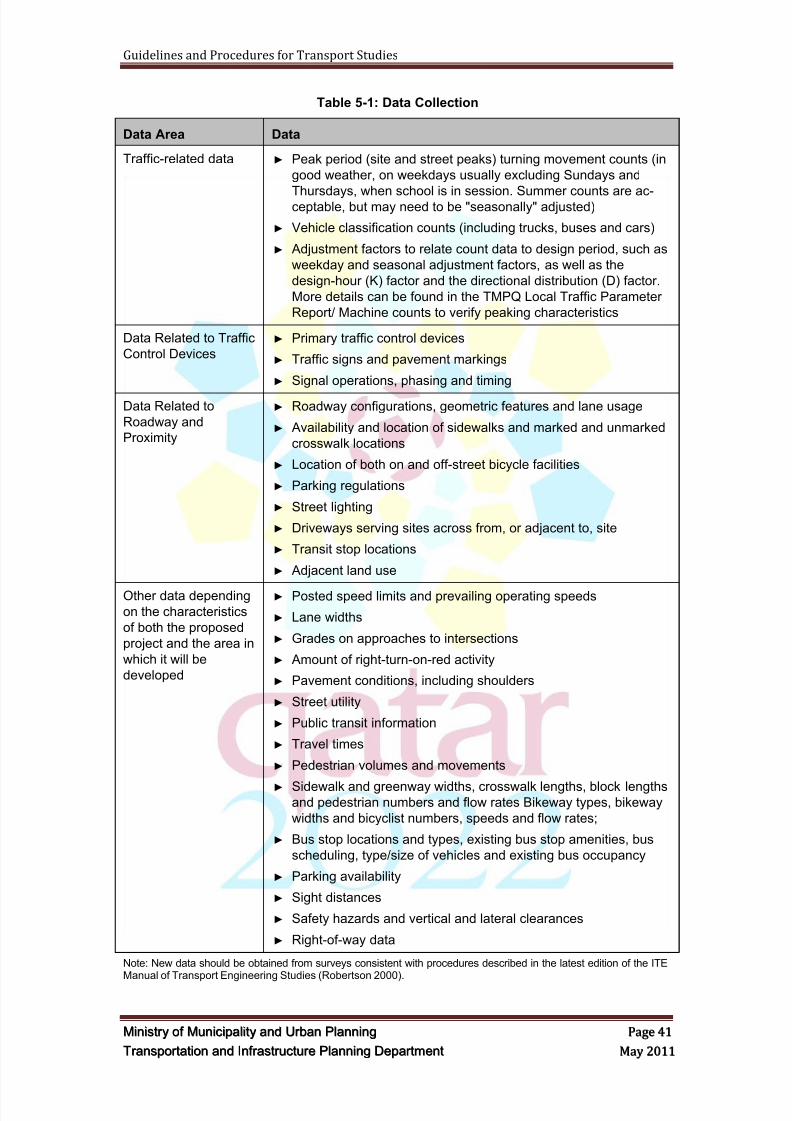
8/9/2019 TIPD Qatar Traffic Manual & Guidelines
http://slidepdf.com/reader/full/tipd-qatar-traffic-manual-guidelines 50/197
Guidelines and Procedures for Transport Studies
MMiinniissttr r yy oof f MMuunniicciippaalliittyy aanndd UUr r bbaann PPllaannnniinngg PPaaggee 4411
TTr r aannssppoor r ttaattiioonn aanndd IInnf f r r aassttr r uuccttuur r ee PPllaannnniinngg DDeeppaar r ttmmeenntt MMaayy 22001111
Table 5-1: Data Collection
Data Area Data
Traffic-related data ► Peak period (site and street peaks) turning movement counts (in
good weather, on weekdays usually excluding Sundays and
Thursdays, when school is in session. Summer counts are ac-ceptable, but may need to be "seasonally" adjusted)
► Vehicle classification counts (including trucks, buses and cars)
► Adjustment factors to relate count data to design period, such as
weekday and seasonal adjustment factors, as well as the
design-hour (K) factor and the directional distribution (D) factor.
More details can be found in the TMPQ Local Traffic Parameter
Report/ Machine counts to verify peaking characteristics
Data Related to Traffic
Control Devices
► Primary traffic control devices
► Traffic signs and pavement markings
► Signal operations, phasing and timing
Data Related to
Roadway and
Proximity
► Roadway configurations, geometric features and lane usage
► Availability and location of sidewalks and marked and unmarked
crosswalk locations
► Location of both on and off-street bicycle facilities
► Parking regulations
► Street lighting
► Driveways serving sites across from, or adjacent to, site
► Transit stop locations
► Adjacent land use
Other data depending
on the characteristics
of both the proposed
project and the area in
which it will be
developed
► Posted speed limits and prevailing operating speeds
► Lane widths
► Grades on approaches to intersections
► Amount of right-turn-on-red activity
► Pavement conditions, including shoulders
► Street utility
► Public transit information
► Travel times
► Pedestrian volumes and movements
► Sidewalk and greenway widths, crosswalk lengths, block lengthsand pedestrian numbers and flow rates Bikeway types, bikeway
widths and bicyclist numbers, speeds and flow rates;
► Bus stop locations and types, existing bus stop amenities, bus
scheduling, type/size of vehicles and existing bus occupancy
► Parking availability
► Sight distances
► Safety hazards and vertical and lateral clearances
► Right-of-way data
Note: New data should be obtained from surveys consistent with procedures described in the latest edition of the ITEManual of Transport Engineering Studies (Robertson 2000).
8/9/2019 TIPD Qatar Traffic Manual & Guidelines
http://slidepdf.com/reader/full/tipd-qatar-traffic-manual-guidelines 51/197
Guidelines and Procedures for Transport Studies
MMiinniissttr r yy oof f MMuunniicciippaalliittyy aanndd UUr r bbaann PPllaannnniinngg PPaaggee 4422
TTr r aannssppoor r ttaattiioonn aanndd IInnf f r r aassttr r uuccttuur r ee PPllaannnniinngg DDeeppaar r ttmmeenntt MMaayy 22001111
Any adjustments to survey data should be described and justified. Developers areencouraged to provide data representing conditions appropriate for analysis, such asaverage, design day, or seasonal peak traffic counts or surveys factored to representall members of a surveyed population. Procedures and factors used will beexplained in summary form.
Any seasonal adjustments will be based on seasonal variations determined fromcounts of similar roadways in similar environments. The appropriate analysis periodwill be selected by the MMUP and the developer. For peak-period analysis, the site'santicipated design-hour volume will often occur during a seasonal peak period. Someuses, such as shopping centres, will have significant seasonal peaks and others likeresidential neighbourhoods will not. Specific characteristics of the developmentunder study will be reviewed before selecting the appropriate design day for whichcounts are to be adjusted.
5.3 Inform ation and Data Col lect ion of Transpo rtat ion Projects
The Consultant shall collect all the required and available information and data of thecurrent and proposed transportation projects. These projects shall be reviewed andanalyzed and a summary shall be provided in the submitted reports.
The following agencies shall be contacted and information on their current andproposed projects within the sub-area model shall be collected:
Ministry of Municipality and Urban Planning
Public Works Authority
Private Engineering Office
Mowasalat Qatari Diar
Utilities companies
5.4 Turning Movement Counts (TMC ’s )
The locations of the Turning Movement Counts (TMC‘s) shall be agreed with MMUP.The TMC‘s shall be classified counts that include the number of Passenger Cars,Trucks and Buses for each movement. The TMC‘s shall consist of three separatecounting periods of 3-hour each, total of 9 hours. The TMC shall be undertaken usingVideo Camera with automated vehicle detection capability software.
These counts should be scheduled to capture the morning, noon, andafternoon/evening peak hours. The scheduling of the TMC‘s shall be determinedfrom the Automatic Traffic Counts (ATC‘s) conducted at or near the intersection(s)being surveyed or as agreed with MMUP. The TMC‘s shall be carried out on aweekday (Mondays, Tuesdays or Wednesdays) or as agreed with MMUP. TheTMC‘s shall be scheduled to capture a realistic representation of typical traffic peakflow and to avoid holidays, special events, nearby road works, and other suchdisruptions to the normal daily traffic patterns.
The results for the TMC‘s shall be submitted by the Consultant, in both written andelectronic formats, in the standard format prescribed by Transportation and
Infrastructure Planning Department, samples of which are available from MMUP. Themethodology for conducting the TMC‘s shall be presented to MMUP. Pedestrian and
8/9/2019 TIPD Qatar Traffic Manual & Guidelines
http://slidepdf.com/reader/full/tipd-qatar-traffic-manual-guidelines 52/197
Guidelines and Procedures for Transport Studies
MMiinniissttr r yy oof f MMuunniicciippaalliittyy aanndd UUr r bbaann PPllaannnniinngg PPaaggee 4433
TTr r aannssppoor r ttaattiioonn aanndd IInnf f r r aassttr r uuccttuur r ee PPllaannnniinngg DDeeppaar r ttmmeenntt MMaayy 22001111
Bicycle movements across the approaches to the intersection shall be counted aswell.
5.5 Automatic Traff ic Counts (Machine/Tube Counts )
The locations of the Automatic Traffic Counts (ATC's) shall be agreed with MMUP.The ATC‘s shall be conducted over a continuous seven (7) days period and shallrecord traffic volume on an hourly basis for 24 hours/day in 15 minutes intervalsthroughout the length of the survey. The ATC‘s shall be for volume, speed andclassification. The ATC‘s shall be scheduled to capture a realistic representation oftypical traffic flow as possible and to avoid holidays, special events, nearby roadworks, and other such disruptions to the normal daily traffic patterns.
The results of the ATC's shall be submitted by the Consultant, in both written andelectronic formats, in the standard format prescribed by Transportation andInfrastructure Planning Department, samples of which are available from MMUP. The ATC's shall also be adjusted for seasonal variations, if available, prior to use in any
traffic analyses.
The raw data from the counting machine shall be submitted as well.
5.6 Manual Classif ied Coun ts (MCC ’s )
The locations of the Manual Classified Counts (MCC‘s) shall be agreed with MMUP.The MCC‘s shall be conducted over a continuous 16 hours period, from 5am to 9pm,and shall record traffic volume on an hourly basis in 15 minutes intervals. The MCC‘s shall be for volume and classification. The MCC‘s shall be scheduled to capture arealistic representation of typical traffic flow as possible and to avoid holidays, special
events, nearby road works, and other such disruptions to the normal daily trafficpatterns.
The results of the MCC‘s shall be submitted by the Consultant, in both written andelectronic formats, in the standard format prescribed by Transportation andInfrastructure Planning Department, samples of which are available from MMUP. TheMCC‘s shall also be adjusted for seasonal variations, if available, prior to use in anytraffic analyses.
5.7 Parking Study and Survey
The Consultant shall identify areas with parking and traffic circulation problems, if
any. The Consultant shall submit the methodology addressing parking and circulationissues that shall include but not limited to the following:
Identify areas such as Mosques, Educational institutions, Commercial andIndustrial, high density Residential, etc. These areas shall be submitted toMMUP for review and approval.
Undertake inventory of the available on-street and off-street parking includingvacant lands.
Carry out parking surveys for these areas. The timing and length of parkingsurveys should accommodate different Land Uses. For example, parkingsurveys for Mosques should be undertaken during Friday prayers orRamadan prayers at night. School parking surveys should be undertakenwhen schools start and end. Surveys in commercial areas should be carried
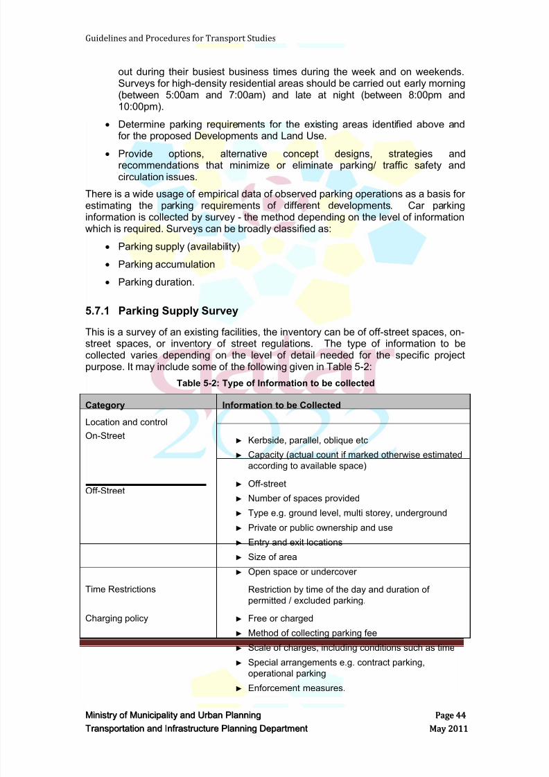
8/9/2019 TIPD Qatar Traffic Manual & Guidelines
http://slidepdf.com/reader/full/tipd-qatar-traffic-manual-guidelines 53/197
Guidelines and Procedures for Transport Studies
MMiinniissttr r yy oof f MMuunniicciippaalliittyy aanndd UUr r bbaann PPllaannnniinngg PPaaggee 4444
TTr r aannssppoor r ttaattiioonn aanndd IInnf f r r aassttr r uuccttuur r ee PPllaannnniinngg DDeeppaar r ttmmeenntt MMaayy 22001111
out during their busiest business times during the week and on weekends.Surveys for high-density residential areas should be carried out early morning(between 5:00am and 7:00am) and late at night (between 8:00pm and10:00pm).
Determine parking requirements for the existing areas identified above and
for the proposed Developments and Land Use.
Provide options, alternative concept designs, strategies andrecommendations that minimize or eliminate parking/ traffic safety andcirculation issues.
There is a wide usage of empirical data of observed parking operations as a basis forestimating the parking requirements of different developments. Car parkinginformation is collected by survey - the method depending on the level of informationwhich is required. Surveys can be broadly classified as:
Parking supply (availability)
Parking accumulation
Parking duration.
5.7.1 Parking Supply Survey
This is a survey of an existing facilities, the inventory can be of off-street spaces, on-street spaces, or inventory of street regulations. The type of information to becollected varies depending on the level of detail needed for the specific projectpurpose. It may include some of the following given in Table 5-2:
Table 5-2: Type of Information to be collected
Category Information to be CollectedLocation and control
On-Street
Off-Street
► Kerbside, parallel, oblique etc
► Capacity (actual count if marked otherwise estimated
according to available space)
► Off-street
► Number of spaces provided
► Type e.g. ground level, multi storey, underground
► Private or public ownership and use
► Entry and exit locations► Size of area
► Open space or undercover
Time Restrictions Restriction by time of the day and duration of
permitted / excluded parking.
Charging policy ► Free or charged
► Method of collecting parking fee
► Scale of charges, including conditions such as time
► Special arrangements e.g. contract parking,
operational parking
► Enforcement measures.
8/9/2019 TIPD Qatar Traffic Manual & Guidelines
http://slidepdf.com/reader/full/tipd-qatar-traffic-manual-guidelines 54/197
Guidelines and Procedures for Transport Studies
MMiinniissttr r yy oof f MMuunniicciippaalliittyy aanndd UUr r bbaann PPllaannnniinngg PPaaggee 4455
TTr r aannssppoor r ttaattiioonn aanndd IInnf f r r aassttr r uuccttuur r ee PPllaannnniinngg DDeeppaar r ttmmeenntt MMaayy 22001111
From the parking inventory and details of restrictions, an evaluation can be made ofthe theoretically available space-hours of parking. This can assist in estimatingpotential parking revenues and assessing alternative charging strategies.
5.7.2 Parking Accumulation Survey
This survey determines the actual number of vehicles parked at a given time at alllocations. When the survey area is a single off-street car park, the method of datacollection is as follows:
Define survey time period, start and end times;
Define survey time blocks, say every 15 or 30 minutes;
Count the number of parked cars at the start of each period;
Record the arrivals and departures over the survey period, for each time
block; and Count number of parked vehicles at the end of survey period, as a check on
observed data.
For each time block, the number of observed arrival minus departures gives the netincrease in car parked, compared with the preceding time block. Therefore, thenumber of cars parked at any time is known. New developments in the application ofintelligent transport systems (ITS) to off-street parking can provide a rich source ofdata.
5.7.3 Parking Duration Survey
This survey quantifies the length of time spent by vehicles parked in the study area.Patrol survey and direct interview of motorists at the survey area are two methodsused to obtain information for parking duration. Patrol survey is done generally byfoot. The survey area is divided into sections where the number of cars together withtheir registration numbers is recorded at a defined time intervals. Direct interview ismore expensive and comprehensive method, where motorists are interviewed at theirplace of parking and questioned concerning their origin, destination, trip purpose andestimated duration of parking. The type of vehicle, the nature of parking, time ofarrival and departure can also be recorded. Data collected by both methods can beanalyzed to obtain a variety of information relating to the survey area, the surveyperiod and a parking usage.
5.8 Travel Time Survey
The primary purpose of Travel Time Survey (TTS) is to identify an effectivemethodology for measuring the travel time through a particular corridor. Specifically,the methodology should accomplish the following:
1. Measure travel time, running time and delay time for each segment of thecorridor in non-peak and peak travel times.
2. Allow an interpreter to identify segments or intersections that have consistentproblems maintaining an average travel speed for the corridor.
3. Allow the study to serve as a benchmark that could be repeated in the future todetermine how travel times may change over time.
8/9/2019 TIPD Qatar Traffic Manual & Guidelines
http://slidepdf.com/reader/full/tipd-qatar-traffic-manual-guidelines 55/197
Guidelines and Procedures for Transport Studies
MMiinniissttr r yy oof f MMuunniicciippaalliittyy aanndd UUr r bbaann PPllaannnniinngg PPaaggee 4466
TTr r aannssppoor r ttaattiioonn aanndd IInnf f r r aassttr r uuccttuur r ee PPllaannnniinngg DDeeppaar r ttmmeenntt MMaayy 22001111
The Consultant shall conduct Travel Time Survey using Moving Observer methods.The Consultant shall use either Floating Car or Chase Car techniques to conduct andcollect travel time.
A passenger in the test vehicle shall record travel times at designated checkpointsusing computer instrumentation to record vehicle speed, travel times or distances atpreset checkpoints or intervals. A Global Positioning System (GPS) receiver coupledwith a portable computer can be used to record the test vehicle‘s position and speedat time intervals as frequent as every second. The methodology for conducting theTTS shall be presented to, and agreed upon with, the Engineer.
The TTS shall be carried out at three separate counting periods of 3-hour each, totalof 9 hours. At least 6 runs per direction per peak period shall be achieved. Theseruns shall be scheduled to capture the travel time of morning, mid-day andafternoon/evening peak hours. The scheduling of the TTS shall be determined fromthe Automatic Traffic Counts conducted along the study route or as agreed with
MMUP. The TTS shall be carried out on a weekday (Mondays, Tuesdays orWednesdays) or as agreed with the Engineer. The TTS shall be scheduled to capturea realistic representation of typical traffic peak flow and to avoid holidays, specialevents, nearby roads works, and other such disruptions to the normal daily trafficpatterns.
The results for the TTS shall be submitted by the Consultant, in both written andelectronic formats, in the standard format prescribed by MMUP, samples of which areavailable from the Engineer.
In addition to the recording of travel time between intersections, which measured atStop or Give-Way lines, the survey shall record the delay and queuing times. It is
suggested that the survey vehicle is joining the back of the queue when the speed ofthe survey vehicle drops to less than 10km/hr.
Furthermore, it might be required to record the travel time to a certain land-mark orlocation such as a major side road or building.
5.9 Pedestr ians and Cycl ists Survey
The Consultant shall submit their methodology for undertaking Pedestrians andCyclists Survey.
5.10 Publ ic Transport Survey
The Consultant shall submit their methodology for undertaking surveys for PublicTransport facilities and commuters.
5.11 Origin – Dest inat ion Survey
The Consultant shall submit their methodology for undertaking Origin – Destination(O-D) Survey.
8/9/2019 TIPD Qatar Traffic Manual & Guidelines
http://slidepdf.com/reader/full/tipd-qatar-traffic-manual-guidelines 56/197
Guidelines and Procedures for Transport Studies
MMiinniissttr r yy oof f MMuunniicciippaalliittyy aanndd UUr r bbaann PPllaannnniinngg PPaaggee 4477
TTr r aannssppoor r ttaattiioonn aanndd IInnf f r r aassttr r uuccttuur r ee PPllaannnniinngg DDeeppaar r ttmmeenntt MMaayy 22001111
5.12 Land use Surv eys and Invest igat ions
The Consultant shall collect all the required and available information and data of thecurrent and proposed land use within the sub-area model. The land use shall bereviewed and analyzed and a summary shall be provided in the submitted reports.
5.13 Traff ic Surveys Requ irements
The Consultant shall follow MMUP requirements for conducting traffic surveys(ATC‘s, MCC‘s, TMC‘s and TTS‘s) as outlined above. The following details shall alsobe considered by the Consultants when conducting surveys and shall be addressedin the submitted methodology report.
5.13.1 General:
1. Drawings shall be submitted that depict the locations of the traffic count and
shall be submitted in AutoCAD format.2. Exact or approximate coordinates of the count locations shall be submitted.
3. The Consultant shall submit a program for the proposed traffic surveys. The
program shall identify all holidays and special events (Eid, schools, public,
religious, etc.) that expect to occur within the survey period. The traffic
surveys shall be completed one week before and/or started one week after
the specific holiday and any special events.
4. For the VISUM and VISSIM models Calibration/Validation process, MMUP
Model requirements shall be met.
5. The Consultant shall ensure the consistency in results between ATC‘s and
TMC‘s. 6. A comparison between the MCC‘s and ATC‘s conducted at the same
locations shall be carried out by the consultant. 10 % percent or less than 100
vehicles/hour is the allowable tolerance between the ATC‘s and MCC‘s
compared.
7. The Consultant shall observe/identify any road closure/diversion and ensure
that all roads and intersections are fully opened prior to any traffic survey.
Road closure/diversion shall be documented and discussed with MMUP. If
the intersection(s)/link(s) will be open within two weeks, then the consultant
has to postpone counting until the closed intersection/link is open or the
consultant can postpone counting the intersection/link until the end of the
counting program.
8. QA/QC shall be performed for all of the surveys collected. Any
inconsistencies or unrealistic values are subject to rejection by MMUP.
9. Row data shall be submitted to MMUP.
10. The required data shall be as in the attached templates as a minimum with
the requirements listed below.
11. The Consultant‘s Traffic Engineer shall supervise all traffic surveys.
5.13.2 ATC’s:
1. ATC Surveys shall be conducted for 7 days, broken down into 15 minintervals with 1 hour totals.
8/9/2019 TIPD Qatar Traffic Manual & Guidelines
http://slidepdf.com/reader/full/tipd-qatar-traffic-manual-guidelines 57/197
8/9/2019 TIPD Qatar Traffic Manual & Guidelines
http://slidepdf.com/reader/full/tipd-qatar-traffic-manual-guidelines 58/197
Guidelines and Procedures for Transport Studies
MMiinniissttr r yy oof f MMuunniicciippaalliittyy aanndd UUr r bbaann PPllaannnniinngg PPaaggee 4499
TTr r aannssppoor r ttaattiioonn aanndd IInnf f r r aassttr r uuccttuur r ee PPllaannnniinngg DDeeppaar r ttmmeenntt MMaayy 22001111
number of personnel conducting the counts shall be outlined in the report and
agreed with MMUP and increased if needed.
4. Required data:
a. Traffic counts shall be conducted in 15 min intervals during the peak
periods and collected to 1 hour totals.
b. Classes shall be shown as (PC, LV and HV).c. Summary table of the traffic volumes broken down to Intervals,
Vehicle types, and peak hour volumes.
d. A diagram showing a simple intersection configuration with the street
names in CAD format, the adjusted/unadjusted traffic volumes per
peak hour and the percentage of the Heavy Vehicles.
5.14 The Traff ic Surv eys An alyses Report
The Consultant shall prepare and submit Traffic Surveys Analyses Report. The report
shall include the following items a minimum:
Project/Development description
Traffic surveys locations including plans
Existing sites condition during the surveys
Site observations and general notes
Traffic surveys data
Traffic surveys summaries
Traffic surveys summaries for peak periods including plans
Seasonal and adjustment factors
Traffic surveys analyses and conclusions
Traffic design volumes
The Traffic Surveys data shall be reviewed by the following personnel:
a. The Senior Traffic/Transport Engineer or the Manager of the TrafficSurvey Firm.
b. The Senior Traffic/Transport Engineer or the Manager of theTransportation Section/Department of the Traffic Consultant Firm.
The Traffic Surveys Analyses Report shall be reviewed by either the SeniorTraffic/Transport Engineer or the Manager of the Transportation Section/ Departmentof the Traffic Consultant Firm who has not been involved in preparing/writing thereport.
5.15 Review Period
The estimated MMUP's technical review time is 10 working days, where extra timewould be required according to the project size.
In case the Traffic Data and the Traffic Surveys Analyses Report is returned as not
approved, the Consultant shall submit the revised data and report within two weeks.
8/9/2019 TIPD Qatar Traffic Manual & Guidelines
http://slidepdf.com/reader/full/tipd-qatar-traffic-manual-guidelines 59/197
Guidelines and Procedures for Transport Studies
MMiinniissttr r yy oof f MMuunniicciippaalliittyy aanndd UUr r bbaann PPllaannnniinngg PPaaggee 5500
TTr r aannssppoor r ttaattiioonn aanndd IInnf f r r aassttr r uuccttuur r ee PPllaannnniinngg DDeeppaar r ttmmeenntt MMaayy 22001111
5.16 Deliverables
The consultant shall submit the following:
The traffic surveys data, one hard copy, usually prepared by the traffic countsurveyors.
The traffic surveys analyses report, two hard copies.
The traffic surveys data, one digital copy.
The traffic surveys analyses report, one digital copy.
The raw data of traffic surveys, one digital copy.
8/9/2019 TIPD Qatar Traffic Manual & Guidelines
http://slidepdf.com/reader/full/tipd-qatar-traffic-manual-guidelines 60/197
Guidelines and Procedures for Transport Studies
MMiinniissttr r yy oof f MMuunniicciippaalliittyy aanndd UUr r bbaann PPllaannnniinngg PPaaggee 5511
TTr r aannssppoor r ttaattiioonn aanndd IInnf f r r aassttr r uuccttuur r ee PPllaannnniinngg DDeeppaar r ttmmeenntt MMaayy 22001111
6 VISUM MODELING AND UPDATE OF THE TRANSPORTMODEL
6.1 Overview
The Transport Master Plan for Qatar (TMPQ) was initiated in 2006 with a set ofprivate and public transport network models starting from 2006 as the base year to2011, 2016 and 2026 using forecasts growths in population and employment forQatar. The Transport Master plan for Qatar is strategically guided by the TMPQtravel demand VISUM model. The model covers the entire State of Qatar andincludes all roads and known land uses to 2026. The model is developed as anactivity chained based model. It represents trip chains of travelers passing from oneactivity to the next, throughout a 24-hour period. The approach is an extension of atraditional four stage multi-modal transport model and includes trip generation, tripdistribution, mode choice and road and public transport assignment models. The tripgeneration stage utilizes the activity profile of households derived from 2004 and2006 census data and a comprehensive household interview survey undertaken in2006. Population is segmented into 20 groups based on nationality, gender, income,age and car ownership with trip chains and time of each activity for each groupprovided in hourly intervals for a full day. Attraction of land uses are categorized into11 groups covering work, education and leisure and personal trips. The modelfeedbacks the travel times of the transport modes for the final mode choice anddestination choice, meaning that after traffic has been assigned to the networkmodel, travel time data are fed back into the demand model to update the distributionand mode choice. Trips are assigned to different modes of travel with change ofmode permitted for the same trip based on utility cost of each mode.
The transport model produces trips for daily and three peak periods of AM, Lunch
time and PM. In the road network vehicles are segregated into six classes; cars,school and company buses, restricted and permitted heavy vehicles and light goodsvehicles. The road network incorporates heavy vehicles restricted area and parkingand congestion pricing areas to allow testing of policy plans. All zones and nodenumberings follow the official planning zone boundaries.
The public transport network incorporates bus, light rail, heavy rail and acomprehensive metro system for different horizon years. Demand matrices areassigned based on a quasi time-table assignment procedure. The effect of fares isincluded in the mode choice.
The TMPQ VISUM model is an important planning tool that is currently used fortesting of many transportation projects in the state of Qatar. MMUP continuouslyupdates the TMPQ model to ensure that model is able to provide robust forecasts forassessment of transportation projects in Qatar.
The following reports describe the methodologies, analysis and components of theTMPQ transport model. They are available to consultants undertaking studies inQatar.
1. Transportation Master Plan for Qatar. Components of a Transportation Model,PTV, 29 Feb 2008
2. Transportation Master Plan for Qatar. Model Implementation Report, PTV, 29Feb 2008
3. Transportation Master Plan for Qatar. Model Calibration and Model ValidationReport (Base Year 2006), PTV, 15 Feb 2008
8/9/2019 TIPD Qatar Traffic Manual & Guidelines
http://slidepdf.com/reader/full/tipd-qatar-traffic-manual-guidelines 61/197
Guidelines and Procedures for Transport Studies
MMiinniissttr r yy oof f MMuunniicciippaalliittyy aanndd UUr r bbaann PPllaannnniinngg PPaaggee 5522
TTr r aannssppoor r ttaattiioonn aanndd IInnf f r r aassttr r uuccttuur r ee PPllaannnniinngg DDeeppaar r ttmmeenntt MMaayy 22001111
The TMPQ strategic models shall be used to build a base and future year scenariosmodel. The model shall be run for the following peak periods:
Morning Peak (AM);
Mid-day Peak (MD); and
Evening Peak (PM).
6.2 Land Use
The Consultant shall review and evaluate the VISUM Models and determine if thereare any development(s) that have not been included or fully incorporated in the latestrevision of TMPQ VISUM Model. The Consultant shall be responsible to collate theinformation in order to include all developments in the model area.
For each Traffic Analysis Zone (TAZ), planning data should include a detailedidentification and combination of the densities of three land use categories:
Category A: Existing long term operational land uses that are not dependent on theInterim Zoning Maps and most likely will continue to operate after the design horizonyear.
Category B: Coming approved and in-process projects that are not dependent onInterim Zoning Maps.
Category C: Remaining Land uses based on Interim Zoning Maps and Master Plansdata conversion.
Consultant should submit soft copies (excel sheets) describing each category andthe total equivalent planning data for each TAZ.
The following format should be used for Category A data:
MainZone
TAZRef
PhotoRef
Existing land useobserved on siteAll available data
(Number ofemployees, GFAs,
GLAs, etc…)
Treatment to beassumed for the
horizon year
Comment
Where land use details of any area are incomplete, the Consultant shall agree withMMUP on appropriate assumptions.
6.3 Planning Data
This Section has been prepared to assist consultants intending to use the TMPQ
model to undertake transport studies in Qatar. It stipulates the daily person trip rates
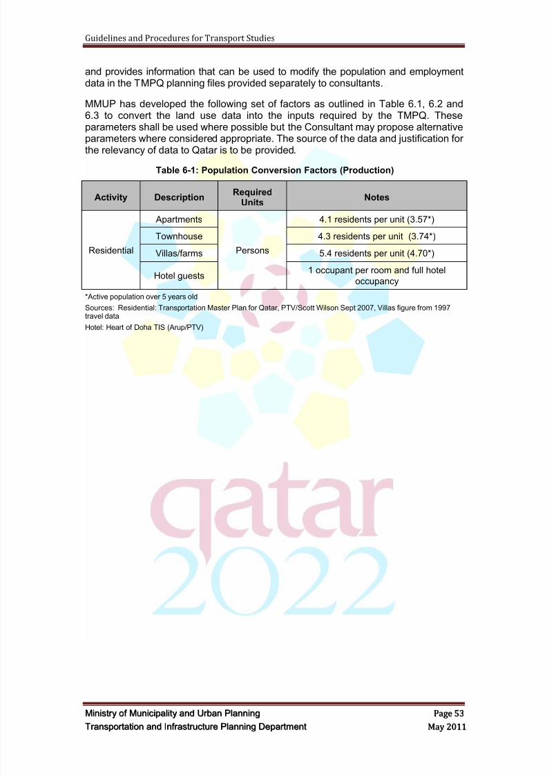
8/9/2019 TIPD Qatar Traffic Manual & Guidelines
http://slidepdf.com/reader/full/tipd-qatar-traffic-manual-guidelines 62/197
Guidelines and Procedures for Transport Studies
MMiinniissttr r yy oof f MMuunniicciippaalliittyy aanndd UUr r bbaann PPllaannnniinngg PPaaggee 5533
TTr r aannssppoor r ttaattiioonn aanndd IInnf f r r aassttr r uuccttuur r ee PPllaannnniinngg DDeeppaar r ttmmeenntt MMaayy 22001111
and provides information that can be used to modify the population and employmentdata in the TMPQ planning files provided separately to consultants.
MMUP has developed the following set of factors as outlined in Table 6.1, 6.2 and6.3 to convert the land use data into the inputs required by the TMPQ. Theseparameters shall be used where possible but the Consultant may propose alternative
parameters where considered appropriate. The source of the data and justification forthe relevancy of data to Qatar is to be provided.
Table 6-1: Population Conversion Factors (Production)
Activity DescriptionRequired
UnitsNotes
Residential
Apartments
Persons
4.1 residents per unit (3.57*)
Townhouse 4.3 residents per unit (3.74*)
Villas/farms 5.4 residents per unit (4.70*)
Hotel guests 1 occupant per room and full hoteloccupancy
*Active population over 5 years old
Sources: Residential: Transportation Master Plan for Qatar, PTV/Scott Wilson Sept 2007, Villas figure from 1997travel data
Hotel: Heart of Doha TIS (Arup/PTV)
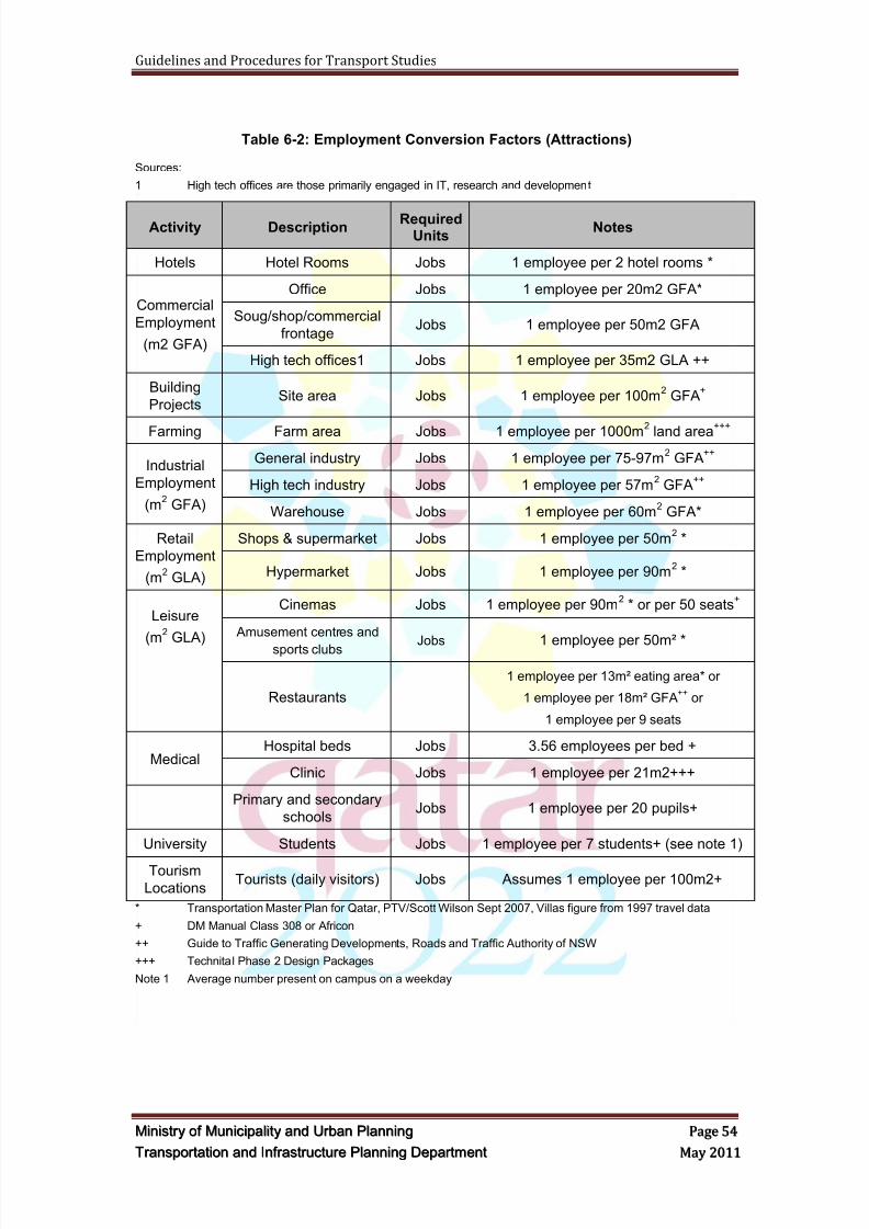
8/9/2019 TIPD Qatar Traffic Manual & Guidelines
http://slidepdf.com/reader/full/tipd-qatar-traffic-manual-guidelines 63/197
Guidelines and Procedures for Transport Studies
MMiinniissttr r yy oof f MMuunniicciippaalliittyy aanndd UUr r bbaann PPllaannnniinngg PPaaggee 5544
TTr r aannssppoor r ttaattiioonn aanndd IInnf f r r aassttr r uuccttuur r ee PPllaannnniinngg DDeeppaar r ttmmeenntt MMaayy 22001111
Table 6-2: Employment Conversion Factors (Attractions)
Sources:
1 High tech offices are those primarily engaged in IT, research and development
* Transportation Master Plan for Qatar, PTV/Scott Wilson Sept 2007, Villas figure from 1997 travel data
+ DM Manual Class 308 or Africon
++ Guide to Traffic Generating Developments, Roads and Traffic Authority of NSW
+++ Technital Phase 2 Design Packages
Note 1 Average number present on campus on a weekday
Activity Description RequiredUnits
Notes
Hotels Hotel Rooms Jobs 1 employee per 2 hotel rooms *
Commercial
Employment
(m2 GFA)
Office Jobs 1 employee per 20m2 GFA*
Soug/shop/commercial
frontageJobs 1 employee per 50m2 GFA
High tech offices1 Jobs 1 employee per 35m2 GLA ++
Building
ProjectsSite area Jobs 1 employee per 100m
2 GFA
+
Farming Farm area Jobs 1 employee per 1000m2 land area+++
Industrial
Employment
(m2 GFA)
General industry Jobs 1 employee per 75-97m2 GFA
++
High tech industry Jobs 1 employee per 57m2 GFA
++
Warehouse Jobs 1 employee per 60m2 GFA*
Retail
Employment
(m2 GLA)
Shops & supermarket Jobs 1 employee per 50m2 *
Hypermarket Jobs 1 employee per 90m2 *
Leisure
(m2 GLA)
Cinemas Jobs 1 employee per 90m2 * or per 50 seats
+
Amusement centres and
sports clubs Jobs 1 employee per 50m² *
Restaurants
1 employee per 13m² eating area* or
1 employee per 18m² GFA++
or
1 employee per 9 seats
MedicalHospital beds Jobs 3.56 employees per bed +
Clinic Jobs 1 employee per 21m2+++
Primary and secondary
schoolsJobs 1 employee per 20 pupils+
University Students Jobs 1 employee per 7 students+ (see note 1)
Tourism
LocationsTourists (daily visitors) Jobs Assumes 1 employee per 100m2+
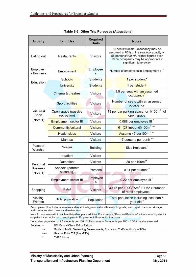
8/9/2019 TIPD Qatar Traffic Manual & Guidelines
http://slidepdf.com/reader/full/tipd-qatar-traffic-manual-guidelines 64/197
Guidelines and Procedures for Transport Studies
MMiinniissttr r yy oof f MMuunniicciippaalliittyy aanndd UUr r bbaann PPllaannnniinngg PPaaggee 5555
TTr r aannssppoor r ttaattiioonn aanndd IInnf f r r aassttr r uuccttuur r ee PPllaannnniinngg DDeeppaar r ttmmeenntt MMaayy 22001111
Table 6-3: Other Trip Purposes (Attractions)
Activity Land UseRequired
UnitsNotes
Eating out Restaurants Visitors
65 seats/100 m². Occupancy may beassumed at 85% of the seating capacity or
55 persons/100 m². Higher figures over100% occupancy may be appropriate if
significant take-away
Employer‘
s BusinessEmployment
Employee
sNumber of employees in Employment III
^
EducationSchools Students 1 per student*
University Students 1 per student
Leisure &
Sport
(Note 1)
Cinema & theatres Visitors3.9 per seat with an assumed
occupancy^
Sport facilities VisitorsNumber of seats with an assumed
occupancy
Open space (passive
recreation)Visitors
13 per car parking space^ or 1/100m
2+of
open space
Employment sector III Visitors 0.088 per employee III^
Community/cultural Visitors 61 (27 inbound)/100m2+++
Health clubs Visitors Assume 45 per100m2 ++
Marinas Visitors 17 persons per berth++
Place ofWorship
Mosque Building Size irrelevant^
Personal
Business
(Note 1)
Inpatient Visitors
Outpatient Visitors 20 per 100m2+
Schools (parents
escorting)Persons 0.31 per student
^
Employment sector IIIEmployee
s0.22 per employee III
^
Shopping Retail Visitors30.15 per 100GFAm
2 + 1.62 x number
of retail employees^
Visiting
FriendsTotal population Population
Total population including less than 5
year old^
Employment III includes wholesale and retail trade, personal and household goods, auto repair, transport storageand communication, hotels and restaurants
Note 1: Land uses within each Activity Group are additive. For example, ―Personal Business‖ is the sum of inpatient +outpatient + school + no. of employees in Employment III sector for that zone
* A student population of 2.5 students per 100m² of land area or 5 students per 100 m² GFA may be assumed
Sources: + DM Manual Class 308 or Africon
++ Guide to Traffic Generating Developments, Roads and Traffic Authority of NSW
+++ Heart of Doha TIS (Arup/PTV)
^ TMPQ Model
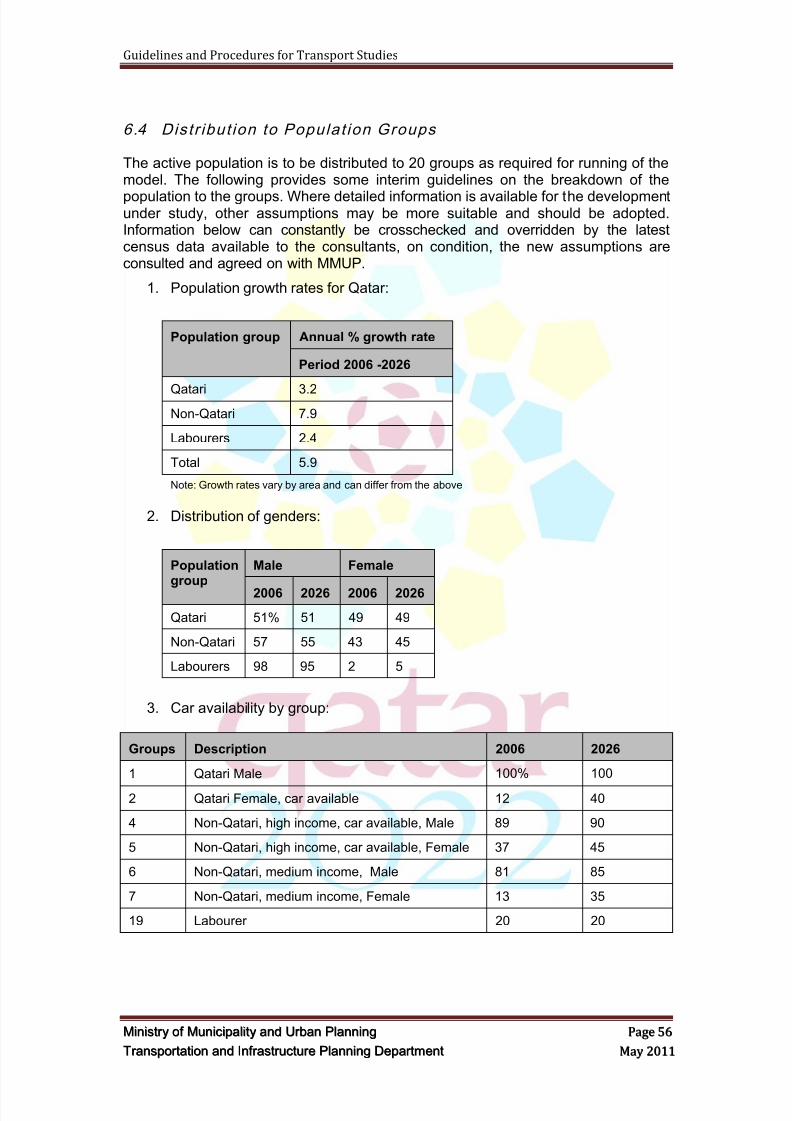
8/9/2019 TIPD Qatar Traffic Manual & Guidelines
http://slidepdf.com/reader/full/tipd-qatar-traffic-manual-guidelines 65/197
Guidelines and Procedures for Transport Studies
MMiinniissttr r yy oof f MMuunniicciippaalliittyy aanndd UUr r bbaann PPllaannnniinngg PPaaggee 5566
TTr r aannssppoor r ttaattiioonn aanndd IInnf f r r aassttr r uuccttuur r ee PPllaannnniinngg DDeeppaar r ttmmeenntt MMaayy 22001111
6.4 Distr ibut ion to Populat ion Groups
The active population is to be distributed to 20 groups as required for running of themodel. The following provides some interim guidelines on the breakdown of the
population to the groups. Where detailed information is available for the developmentunder study, other assumptions may be more suitable and should be adopted.Information below can constantly be crosschecked and overridden by the latestcensus data available to the consultants, on condition, the new assumptions areconsulted and agreed on with MMUP.
1. Population growth rates for Qatar:
Population group Annual % growth rate
Period 2006 -2026
Qatari 3.2
Non-Qatari 7.9
Labourers 2.4
Total 5.9
Note: Growth rates vary by area and can differ from the above
2. Distribution of genders:
Populationgroup
Male Female
2006 2026 2006 2026
Qatari 51% 51 49 49
Non-Qatari 57 55 43 45
Labourers 98 95 2 5
3. Car availability by group:
Groups Description 2006 2026
1 Qatari Male 100% 100
2 Qatari Female, car available 12 40
4 Non-Qatari, high income, car available, Male 89 90
5 Non-Qatari, high income, car available, Female 37 45
6 Non-Qatari, medium income, Male 81 85
7 Non-Qatari, medium income, Female 13 35
19 Labourer 20 20
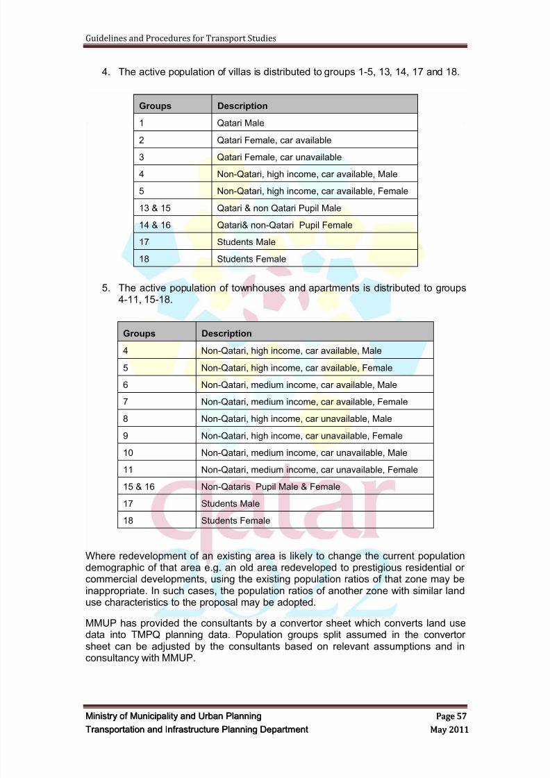
8/9/2019 TIPD Qatar Traffic Manual & Guidelines
http://slidepdf.com/reader/full/tipd-qatar-traffic-manual-guidelines 66/197
Guidelines and Procedures for Transport Studies
MMiinniissttr r yy oof f MMuunniicciippaalliittyy aanndd UUr r bbaann PPllaannnniinngg PPaaggee 5577
TTr r aannssppoor r ttaattiioonn aanndd IInnf f r r aassttr r uuccttuur r ee PPllaannnniinngg DDeeppaar r ttmmeenntt MMaayy 22001111
4. The active population of villas is distributed to groups 1-5, 13, 14, 17 and 18.
Groups Description
1 Qatari Male
2 Qatari Female, car available
3 Qatari Female, car unavailable
4 Non-Qatari, high income, car available, Male
5 Non-Qatari, high income, car available, Female
13 & 15 Qatari & non Qatari Pupil Male
14 & 16 Qatari& non-Qatari Pupil Female
17 Students Male
18 Students Female
5. The active population of townhouses and apartments is distributed to groups4-11, 15-18.
Groups Description
4 Non-Qatari, high income, car available, Male
5 Non-Qatari, high income, car available, Female
6 Non-Qatari, medium income, car available, Male
7 Non-Qatari, medium income, car available, Female
8 Non-Qatari, high income, car unavailable, Male
9 Non-Qatari, high income, car unavailable, Female
10 Non-Qatari, medium income, car unavailable, Male
11 Non-Qatari, medium income, car unavailable, Female
15 & 16 Non-Qataris Pupil Male & Female
17 Students Male
18 Students Female
Where redevelopment of an existing area is likely to change the current populationdemographic of that area e.g. an old area redeveloped to prestigious residential orcommercial developments, using the existing population ratios of that zone may beinappropriate. In such cases, the population ratios of another zone with similar landuse characteristics to the proposal may be adopted.
MMUP has provided the consultants by a convertor sheet which converts land usedata into TMPQ planning data. Population groups split assumed in the convertorsheet can be adjusted by the consultants based on relevant assumptions and inconsultancy with MMUP.
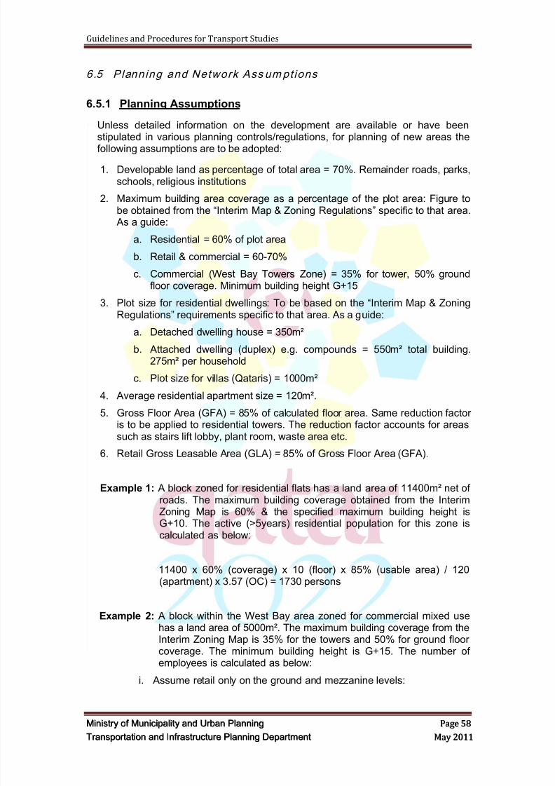
8/9/2019 TIPD Qatar Traffic Manual & Guidelines
http://slidepdf.com/reader/full/tipd-qatar-traffic-manual-guidelines 67/197
Guidelines and Procedures for Transport Studies
MMiinniissttr r yy oof f MMuunniicciippaalliittyy aanndd UUr r bbaann PPllaannnniinngg PPaaggee 5588
TTr r aannssppoor r ttaattiioonn aanndd IInnf f r r aassttr r uuccttuur r ee PPllaannnniinngg DDeeppaar r ttmmeenntt MMaayy 22001111
6.5 Planning and Network Ass umptions
6.5.1 Planning Assumptions
Unless detailed information on the development are available or have been
stipulated in various planning controls/regulations, for planning of new areas thefollowing assumptions are to be adopted:
1. Developable land as percentage of total area = 70%. Remainder roads, parks,schools, religious institutions
2. Maximum building area coverage as a percentage of the plot area: Figure tobe obtained from the ―Interim Map & Zoning Regulations‖ specific to that area. As a guide:
a. Residential = 60% of plot area
b. Retail & commercial = 60-70%
c. Commercial (West Bay Towers Zone) = 35% for tower, 50% groundfloor coverage. Minimum building height G+15
3. Plot size for residential dwellings: To be based on the ―Interim Map & ZoningRegulations‖ requirements specific to that area. As a guide:
a. Detached dwelling house = 350m²
b. Attached dwelling (duplex) e.g. compounds = 550m² total building.275m² per household
c. Plot size for villas (Qataris) = 1000m²
4. Average residential apartment size = 120m².
5. Gross Floor Area (GFA) = 85% of calculated floor area. Same reduction factoris to be applied to residential towers. The reduction factor accounts for areassuch as stairs lift lobby, plant room, waste area etc.
6. Retail Gross Leasable Area (GLA) = 85% of Gross Floor Area (GFA).
Example 1: A block zoned for residential flats has a land area of 11400m² net ofroads. The maximum building coverage obtained from the InterimZoning Map is 60% & the specified maximum building height isG+10. The active (>5years) residential population for this zone iscalculated as below:
11400 x 60% (coverage) x 10 (floor) x 85% (usable area) / 120(apartment) x 3.57 (OC) = 1730 persons
Example 2: A block within the West Bay area zoned for commercial mixed usehas a land area of 5000m². The maximum building coverage from theInterim Zoning Map is 35% for the towers and 50% for ground floorcoverage. The minimum building height is G+15. The number ofemployees is calculated as below:
i. Assume retail only on the ground and mezzanine levels:
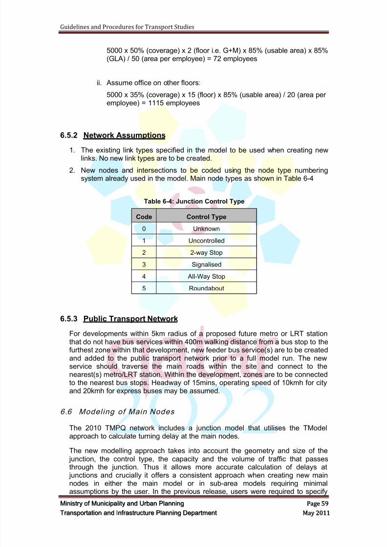
8/9/2019 TIPD Qatar Traffic Manual & Guidelines
http://slidepdf.com/reader/full/tipd-qatar-traffic-manual-guidelines 68/197
Guidelines and Procedures for Transport Studies
MMiinniissttr r yy oof f MMuunniicciippaalliittyy aanndd UUr r bbaann PPllaannnniinngg PPaaggee 5599
TTr r aannssppoor r ttaattiioonn aanndd IInnf f r r aassttr r uuccttuur r ee PPllaannnniinngg DDeeppaar r ttmmeenntt MMaayy 22001111
5000 x 50% (coverage) x 2 (floor i.e. G+M) x 85% (usable area) x 85%(GLA) / 50 (area per employee) = 72 employees
ii. Assume office on other floors:
5000 x 35% (coverage) x 15 (floor) x 85% (usable area) / 20 (area peremployee) = 1115 employees
6.5.2 Network Assumptions
1. The existing link types specified in the model to be used when creating newlinks. No new link types are to be created.
2. New nodes and intersections to be coded using the node type numberingsystem already used in the model. Main node types as shown in Table 6-4
Table 6-4: Junction Control Type
Code Control Type
0 Unknown
1 Uncontrolled
2 2-way Stop
3 Signalised
4 All-Way Stop
5 Roundabout
6.5.3 Public Transport Network
For developments within 5km radius of a proposed future metro or LRT stationthat do not have bus services within 400m walking distance from a bus stop to thefurthest zone within that development, new feeder bus service(s) are to be createdand added to the public transport network prior to a full model run. The newservice should traverse the main roads within the site and connect to thenearest(s) metro/LRT station. Within the development, zones are to be connected
to the nearest bus stops. Headway of 15mins, operating speed of 10kmh for cityand 20kmh for express buses may be assumed.
6.6 Model ing of Main Nodes
The 2010 TMPQ network includes a junction model that utilises the TModelapproach to calculate turning delay at the main nodes.
The new modelling approach takes into account the geometry and size of the junction, the control type, the capacity and the volume of traffic that passesthrough the junction. Thus it allows more accurate calculation of delays at junctions and crucially it offers a consistent approach when creating new mainnodes in either the main model or in sub-area models requiring minimalassumptions by the user. In the previous release, users were required to specify
8/9/2019 TIPD Qatar Traffic Manual & Guidelines
http://slidepdf.com/reader/full/tipd-qatar-traffic-manual-guidelines 69/197
Guidelines and Procedures for Transport Studies
MMiinniissttr r yy oof f MMuunniicciippaalliittyy aanndd UUr r bbaann PPllaannnniinngg PPaaggee 6600
TTr r aannssppoor r ttaattiioonn aanndd IInnf f r r aassttr r uuccttuur r ee PPllaannnniinngg DDeeppaar r ttmmeenntt MMaayy 22001111
main turn delays and capacities for every movement at the junction and inputthese values for each turn. In practice, these values were shown to be not alwaysconsistent in the model and also difficult to estimate or forecast for intersectionswith unknown designs and capacities.
6.6.1 TModel Methodology
In the Tmodel approach, turning movement delays at intersections are calculatedin three stages:
Turn delay(Tcur) = delay in travelling thru the intersection (t0) + delay waiting forgreen or gap(t0)+ delay due to other vehicles or congestion delay
All three components of the turn delays are calculated by VISUM. The first twodelays are calculated by setting up a number of user-defined attributes tocalculate and store the delays. Delay due to other vehicles or congestion delay iscalculated entirely by VISUM using node delay functions that are assigned to each
main node type in the Procedures screen. The methodology is described in moredetails below.
6.6.2 Junction Modeling
The junction model takes into account the control type and the size of the node.The ‗size‘ of the node is derived from the number of lanes on the incoming linksand only links that are open for at least one private transport system are taken intoaccount. The time needed for driving through the main node is also added to thedelay.
The following VISUM parameters are required to be provided for the modelling of
the main nodes and main turns:
Main node capacity (t0/CapPrt),
Turn delay,
Node VD function..
6.6.2.1 Main Node Capacity/Delay
The capacity of a main node is dependent on the type of control at the intersection
and size of the node determined by the number of approach lanes to theintersection from all directions. Table 6-5 show the junction control type used inVISUM. Table 6-6 gives an overview of the generic node parameters used in theTMPQ model.
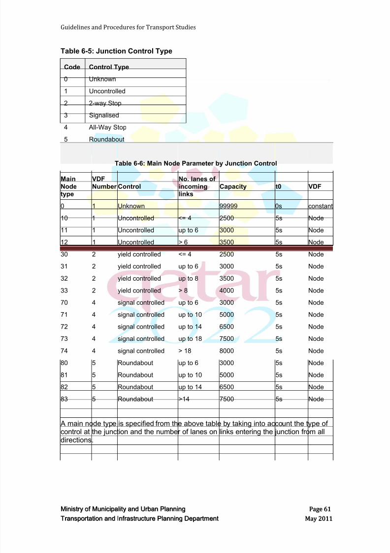
8/9/2019 TIPD Qatar Traffic Manual & Guidelines
http://slidepdf.com/reader/full/tipd-qatar-traffic-manual-guidelines 70/197
Guidelines and Procedures for Transport Studies
MMiinniissttr r yy oof f MMuunniicciippaalliittyy aanndd UUr r bbaann PPllaannnniinngg PPaaggee 6611
TTr r aannssppoor r ttaattiioonn aanndd IInnf f r r aassttr r uuccttuur r ee PPllaannnniinngg DDeeppaar r ttmmeenntt MMaayy 22001111
Table 6-5: Junction Control Type
Code Control Type
0 Unknown
1 Uncontrolled
2 2-way Stop
3 Signalised
4 All-Way Stop
5 Roundabout
Table 6-6: Main Node Parameter by Junction Control
MainNode
type
VDFNumber Control
No. lanes ofincoming
links
Capacity t0 VDF
0 1 Unknown 99999 0s constant
10 1 Uncontrolled <= 4 2500 5s Node
11 1 Uncontrolled up to 6 3000 5s Node
12 1 Uncontrolled > 6 3500 5s Node
30 2 yield controlled <= 4 2500 5s Node
31 2 yield controlled up to 6 3000 5s Node
32 2 yield controlled up to 8 3500 5s Node
33 2 yield controlled > 8 4000 5s Node
70 4 signal controlled up to 6 3000 5s Node
71 4 signal controlled up to 10 5000 5s Node
72 4 signal controlled up to 14 6500 5s Node
73 4 signal controlled up to 18 7500 5s Node
74 4 signal controlled > 18 8000 5s Node
80 5 Roundabout up to 6 3000 5s Node
81 5 Roundabout up to 10 5000 5s Node
82 5 Roundabout up to 14 6500 5s Node
83 5 Roundabout >14 7500 5s Node
A main node type is specified from the above table by taking into account the type ofcontrol at the junction and the number of lanes on links entering the junction from alldirections.
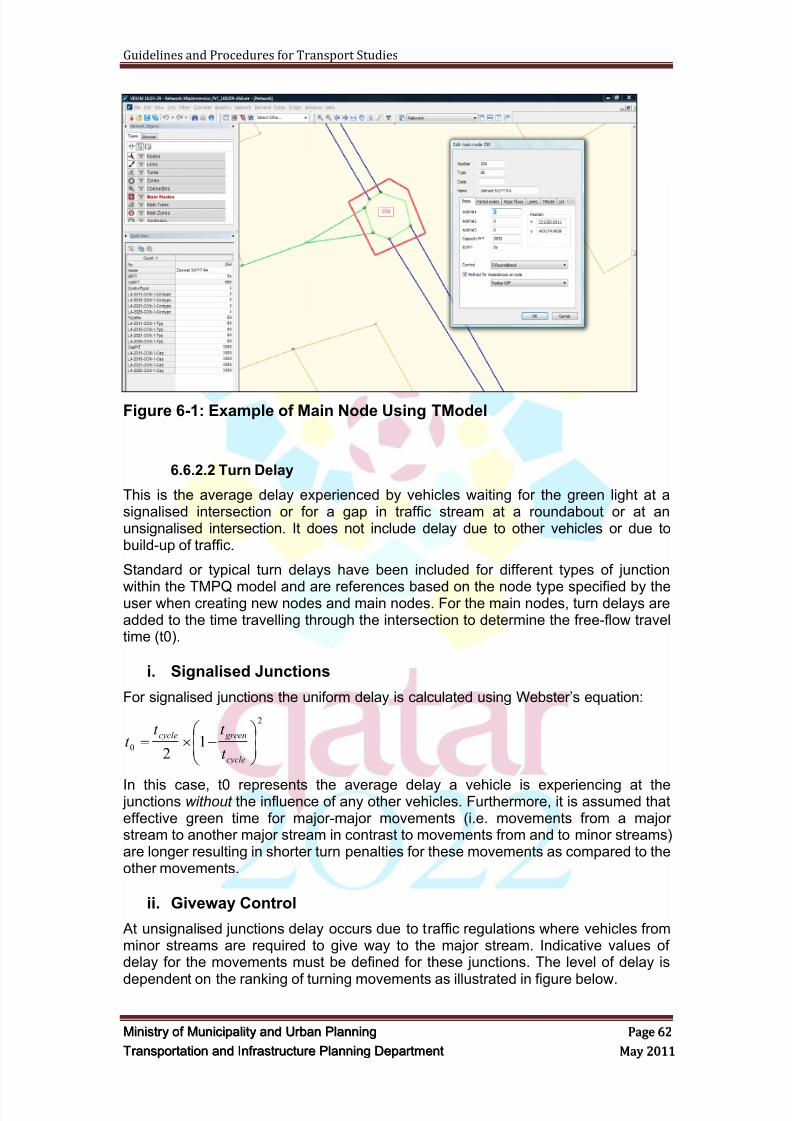
8/9/2019 TIPD Qatar Traffic Manual & Guidelines
http://slidepdf.com/reader/full/tipd-qatar-traffic-manual-guidelines 71/197
Guidelines and Procedures for Transport Studies
MMiinniissttr r yy oof f MMuunniicciippaalliittyy aanndd UUr r bbaann PPllaannnniinngg PPaaggee 6622
TTr r aannssppoor r ttaattiioonn aanndd IInnf f r r aassttr r uuccttuur r ee PPllaannnniinngg DDeeppaar r ttmmeenntt MMaayy 22001111
Figure 6-1: Example of Main Node Using TModel
6.6.2.2 Turn Delay
This is the average delay experienced by vehicles waiting for the green light at asignalised intersection or for a gap in traffic stream at a roundabout or at anunsignalised intersection. It does not include delay due to other vehicles or due tobuild-up of traffic.
Standard or typical turn delays have been included for different types of junction
within the TMPQ model and are references based on the node type specified by theuser when creating new nodes and main nodes. For the main nodes, turn delays areadded to the time travelling through the intersection to determine the free-flow traveltime (t0).
i. Signalised Junctions
For signalised junctions the uniform delay is calculated using Webster‘s equation:
2
01
2
cycle
greencycle
t
t t t
In this case, t0 represents the average delay a vehicle is experiencing at the junctions without the influence of any other vehicles. Furthermore, it is assumed thateffective green time for major-major movements (i.e. movements from a majorstream to another major stream in contrast to movements from and to minor streams)are longer resulting in shorter turn penalties for these movements as compared to theother movements.
ii. Giveway Control
At unsignalised junctions delay occurs due to traffic regulations where vehicles fromminor streams are required to give way to the major stream. Indicative values ofdelay for the movements must be defined for these junctions. The level of delay is
dependent on the ranking of turning movements as illustrated in figure below.
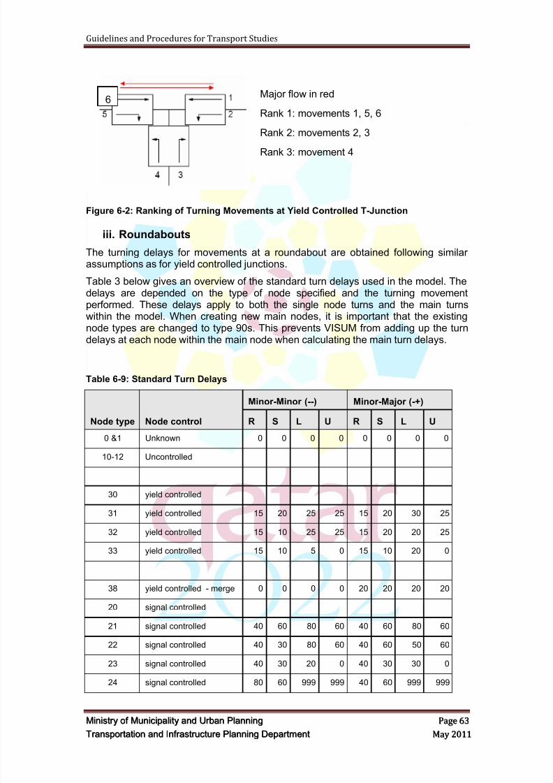
8/9/2019 TIPD Qatar Traffic Manual & Guidelines
http://slidepdf.com/reader/full/tipd-qatar-traffic-manual-guidelines 72/197
Guidelines and Procedures for Transport Studies
MMiinniissttr r yy oof f MMuunniicciippaalliittyy aanndd UUr r bbaann PPllaannnniinngg PPaaggee 6633
TTr r aannssppoor r ttaattiioonn aanndd IInnf f r r aassttr r uuccttuur r ee PPllaannnniinngg DDeeppaar r ttmmeenntt MMaayy 22001111
Major flow in red
Rank 1: movements 1, 5, 6
Rank 2: movements 2, 3Rank 3: movement 4
Figure 6-2: Ranking of Turning Movements at Yield Controlled T-Junction
iii. Roundabouts
The turning delays for movements at a roundabout are obtained following similarassumptions as for yield controlled junctions.
Table 3 below gives an overview of the standard turn delays used in the model. Thedelays are depended on the type of node specified and the turning movementperformed. These delays apply to both the single node turns and the main turnswithin the model. When creating new main nodes, it is important that the existingnode types are changed to type 90s. This prevents VISUM from adding up the turndelays at each node within the main node when calculating the main turn delays.
Table 6-9: Standard Turn Delays
Node type Node control
Minor-Minor (--) Minor-Major (-+)
R S L U R S L U
0 &1 Unknown 0 0 0 0 0 0 0 0
10-12 Uncontrolled
30 yield controlled
31 yield controlled 15 20 25 25 15 20 30 25
32 yield controlled 15 10 25 25 15 20 20 25
33 yield controlled 15 10 5 0 15 10 20 0
38 yield controlled - merge 0 0 0 0 20 20 20 20
20 signal controlled
21 signal controlled 40 60 80 60 40 60 80 60
22 signal controlled 40 30 80 60 40 60 50 60
23 signal controlled 40 30 20 0 40 30 30 0
24 signal controlled 80 60 999 999 40 60 999 999
6

8/9/2019 TIPD Qatar Traffic Manual & Guidelines
http://slidepdf.com/reader/full/tipd-qatar-traffic-manual-guidelines 73/197
Guidelines and Procedures for Transport Studies
MMiinniissttr r yy oof f MMuunniicciippaalliittyy aanndd UUr r bbaann PPllaannnniinngg PPaaggee 6644
TTr r aannssppoor r ttaattiioonn aanndd IInnf f r r aassttr r uuccttuur r ee PPllaannnniinngg DDeeppaar r ttmmeenntt MMaayy 22001111
Node type Node control
Minor-Minor (--) Minor-Major (-+)
R S L U R S L U
41 Roundabout 0 0 0 999 30 30 30 999
42 Roundabout
43 Roundabout 0 0 0 999 60 60 60 999
60 Special 0 0 999 0 0 0 999 0
70s Main node signal 40 40 45 50 35 35 40 45
80s Main node Roundabout 10 10 10 10 10 10 10 10
90s Dummy 0 0 0 0 0 0 0 0
Node type Node control
Major-Minor (+-) Major-Major (++)
R S L U R S L U
0 &1 Unknown 0 0 0 0 0 0 0 0
10-12 Uncontrolled
30 yield controlled
31 yield controlled 10 15 20 25 0 0 0 0
32 yield controlled 10 15 10 25 0 0 0 0
33 yield controlled 10 15 10 0 0 0 0 0
38 yield controlled - merge 0 0 0 0 0 0 0 0
20 signal controlled
21 signal controlled 20 60 60 40 20 40 40 40
22 signal controlled 20 60 30 40 20 40 40 0
23 signal controlled 20 40 10 0 20 20 0 0
24 signal controlled 20 80 999 999 40 40 999 999
41 Roundabout 0 0 0 999 0 0 0 999
42 Roundabout
43 Roundabout 0 0 0 999 0 0 0 999
60 Special 0 0 999 0 0 0 999 0
70s Main node Signal 30 30 35 40 25 25 30 35
80s Main node Roundabout 5 5 5 5 5 5 5 5
90s Dummy 0 0 0 0 0 0 0 0
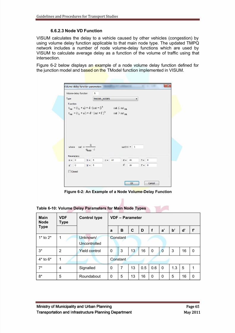
8/9/2019 TIPD Qatar Traffic Manual & Guidelines
http://slidepdf.com/reader/full/tipd-qatar-traffic-manual-guidelines 74/197
Guidelines and Procedures for Transport Studies
MMiinniissttr r yy oof f MMuunniicciippaalliittyy aanndd UUr r bbaann PPllaannnniinngg PPaaggee 6655
TTr r aannssppoor r ttaattiioonn aanndd IInnf f r r aassttr r uuccttuur r ee PPllaannnniinngg DDeeppaar r ttmmeenntt MMaayy 22001111
6.6.2.3 Node VD Function
VISUM calculates the delay to a vehicle caused by other vehicles (congestion) byusing volume delay function applicable to that main node type. The updated TMPQnetwork includes a number of node volume-delay functions which are used byVISUM to calculate average delay as a function of the volume of traffic using that
intersection.
Figure 6-2 below displays an example of a node volume delay function defined forthe junction model and based on the TModel function implemented in VISUM.
Figure 6-2: An Example of a Node Volume-Delay Function
Table 6-10: Volume Delay Parameters for Main Node Types
MainNodeType
VDFType
Control type VDF – Parameter
a B C D f a’ b’ d’ f’
1* to 2* 1 Unknown/
Uncontrolled
Constant
3* 2 Yield control 0 3 13 16 0 0 3 16 0
4* to 6* 1 Constant
7* 4 Signalled 0 7 13 0.5 0.6 0 1.3 5 1
8* 5 Roundabout 0 5 13 16 0 0 5 16 0
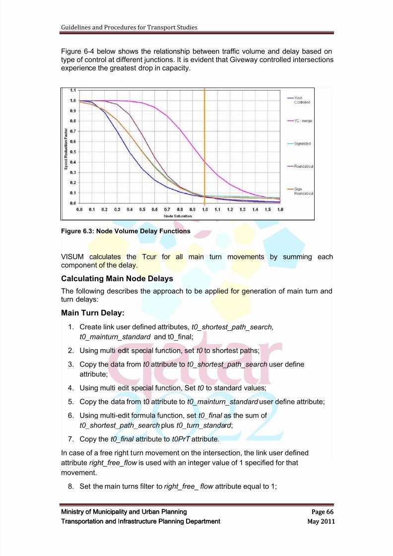
8/9/2019 TIPD Qatar Traffic Manual & Guidelines
http://slidepdf.com/reader/full/tipd-qatar-traffic-manual-guidelines 75/197
Guidelines and Procedures for Transport Studies
MMiinniissttr r yy oof f MMuunniicciippaalliittyy aanndd UUr r bbaann PPllaannnniinngg PPaaggee 6666
TTr r aannssppoor r ttaattiioonn aanndd IInnf f r r aassttr r uuccttuur r ee PPllaannnniinngg DDeeppaar r ttmmeenntt MMaayy 22001111
Figure 6-4 below shows the relationship between traffic volume and delay based ontype of control at different junctions. It is evident that Giveway controlled intersectionsexperience the greatest drop in capacity.
Figure 6.3: Node Volume Delay Functions
VISUM calculates the Tcur for all main turn movements by summing eachcomponent of the delay.
Calculating Main Node Delays
The following describes the approach to be applied for generation of main turn andturn delays:
Main Turn Delay:
1. Create link user defined attributes, t0_shortest_path_search,
t0_mainturn_standard and t0_final;
2. Using multi edit special function, set t0 to shortest paths;
3. Copy the data from t0 attribute to t0_shortest_path_search user define
attribute;
4. Using multi edit special function, Set t0 to standard values;
5. Copy the data from t0 attribute to t0_mainturn_standard user define attribute;
6. Using multi-edit formula function, set t0_final as the sum of
t0_shortest_path_search plus t0_turn_standard ;
7. Copy the t0_final attribute to t0PrT attribute.
In case of a free right turn movement on the intersection, the link user defined
attribute right_free_flow is used with an integer value of 1 specified for that
movement.
8. Set the main turns filter to right_free_ flow attribute equal to 1;
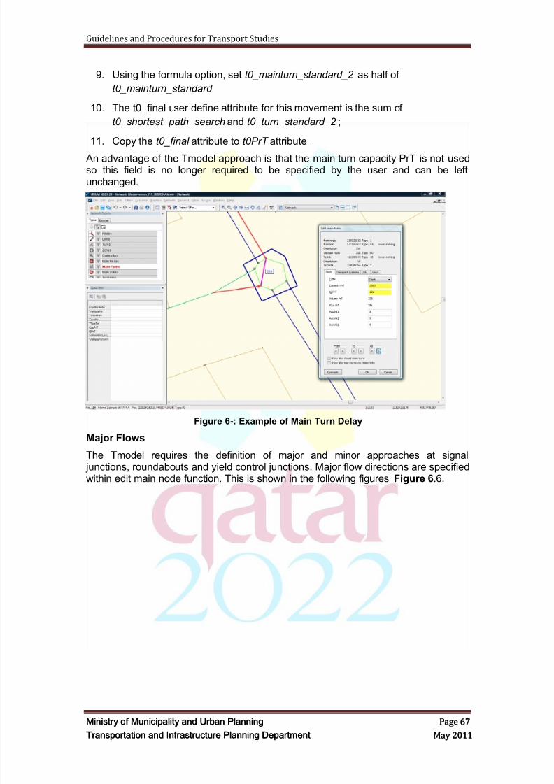
8/9/2019 TIPD Qatar Traffic Manual & Guidelines
http://slidepdf.com/reader/full/tipd-qatar-traffic-manual-guidelines 76/197
Guidelines and Procedures for Transport Studies
MMiinniissttr r yy oof f MMuunniicciippaalliittyy aanndd UUr r bbaann PPllaannnniinngg PPaaggee 6677
TTr r aannssppoor r ttaattiioonn aanndd IInnf f r r aassttr r uuccttuur r ee PPllaannnniinngg DDeeppaar r ttmmeenntt MMaayy 22001111
9. Using the formula option, set t0_mainturn_standard_2 as half of
t0_mainturn_standard
10. The t0_final user define attribute for this movement is the sum of
t0_shortest_path_search and t0_turn_standard_2 ;
11. Copy the t0_final attribute to t0PrT attribute.
An advantage of the Tmodel approach is that the main turn capacity PrT is not usedso this field is no longer required to be specified by the user and can be leftunchanged.
Figure 6-: Example of Main Turn Delay
Major Flows
The Tmodel requires the definition of major and minor approaches at signal junctions, roundabouts and yield control junctions. Major flow directions are specifiedwithin edit main node function. This is shown in the following figures Figure 6.6.
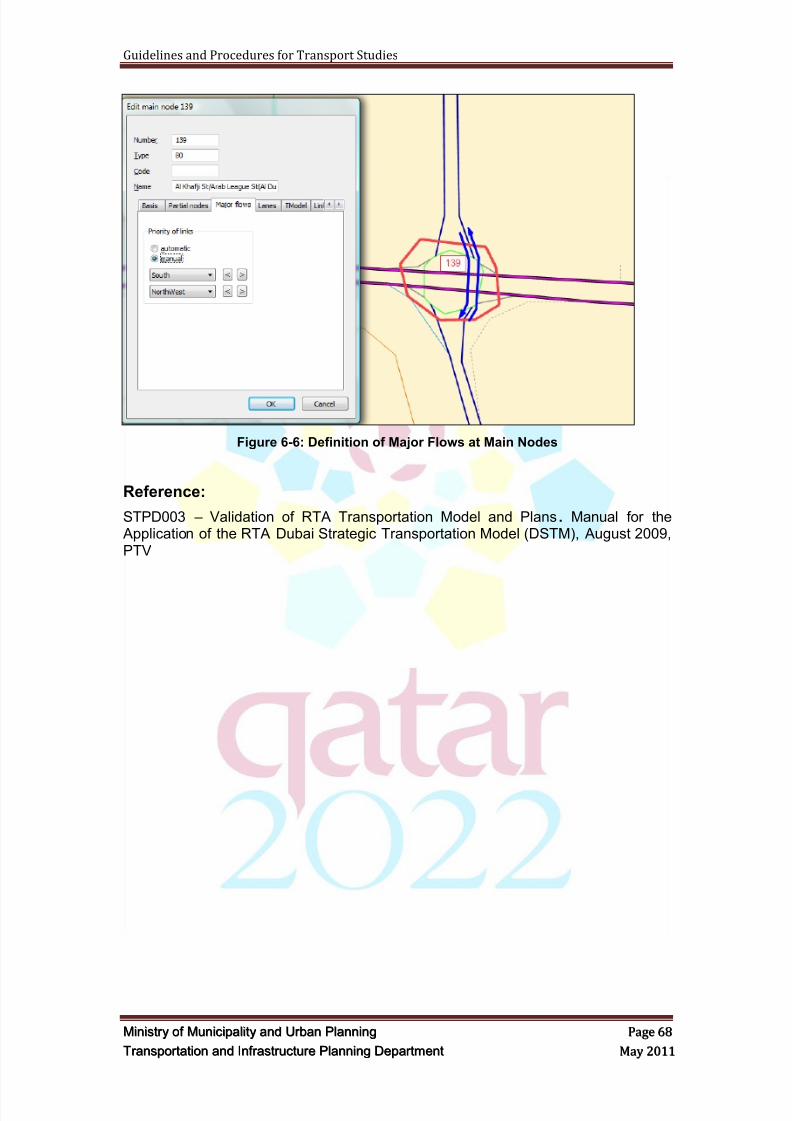
8/9/2019 TIPD Qatar Traffic Manual & Guidelines
http://slidepdf.com/reader/full/tipd-qatar-traffic-manual-guidelines 77/197
Guidelines and Procedures for Transport Studies
MMiinniissttr r yy oof f MMuunniicciippaalliittyy aanndd UUr r bbaann PPllaannnniinngg PPaaggee 6688
TTr r aannssppoor r ttaattiioonn aanndd IInnf f r r aassttr r uuccttuur r ee PPllaannnniinngg DDeeppaar r ttmmeenntt MMaayy 22001111
Figure 6-6: Definition of Major Flows at Main Nodes
Reference:
STPD003 – Validation of RTA Transportation Model and Plans. Manual for the Application of the RTA Dubai Strategic Transportation Model (DSTM), August 2009,PTV

8/9/2019 TIPD Qatar Traffic Manual & Guidelines
http://slidepdf.com/reader/full/tipd-qatar-traffic-manual-guidelines 78/197
Guidelines and Procedures for Transport Studies
MMiinniissttr r yy oof f MMuunniicciippaalliittyy aanndd UUr r bbaann PPllaannnniinngg PPaaggee 6699
TTr r aannssppoor r ttaattiioonn aanndd IInnf f r r aassttr r uuccttuur r ee PPllaannnniinngg DDeeppaar r ttmmeenntt MMaayy 22001111
Table 6-11: Main Node Parameters by Type
Nodetype
ControlNo. lanes of
incoming linksCapacity t0 VDF
0 & 1 Unknown/neutral 99999 0s constant
10 Uncontrolled <= 4 2500 5s Node
11 Uncontrolled up to 6 3000 5s Node
12 Uncontrolled > 6 3500 5s Node
30 yield controlled <= 4 2500 5s Node
31 yield controlled up to 6 3000 5s Node
32 yield controlled up to 8 3500 5s Node
33 yield controlled > 8 4000 5s Node
38 yield controlled – merge Sum of capacity ofoutgoing links
5s Node
70 signal controlled up to 6 3000 5s Node
71 signal controlled up to 10 4000 5s Node
72 signal controlled up to 14 5000 5s Node
73 signal controlled up to 18 5500 5s Node
74 signal controlled > 18 6000 5s Node
80 Roundabout up to 6 3000 5s Node
81 Roundabout up to 10 4000 5s Node
82 Roundabout up to 14 5000 5s Node
83 Roundabout >14 5500 5s Node
60Roundabout signal
controlledup to 6 3000 5s Node
61Roundabout signal
controlledup to 10 4000 5s Node
62Roundabout signal
controlledup to 14 5000 5s Node
63Roundabout signal
controlled >14 5500 5s Node
8/9/2019 TIPD Qatar Traffic Manual & Guidelines
http://slidepdf.com/reader/full/tipd-qatar-traffic-manual-guidelines 79/197
Guidelines and Procedures for Transport Studies
MMiinniissttr r yy oof f MMuunniicciippaalliittyy aanndd UUr r bbaann PPllaannnniinngg PPaaggee 7700
TTr r aannssppoor r ttaattiioonn aanndd IInnf f r r aassttr r uuccttuur r ee PPllaannnniinngg DDeeppaar r ttmmeenntt MMaayy 22001111
6.7 Latest Model Struct ure
The Latest model version has a master file structure, and contains a scenariomanager where you can switch between different years of the model, and thedifferent peaks of the day.
Prt network Links are common for all scenario years, but their attributes (type andstandard values) are different and defined separately per year.
Put routes are common for all years, but there is an automatic filter which definesactive routes per each scenario year.
Main nodes are common for all years, in terms of their geometry (locations andboundaries), while their attributes (type, control type, and capacity) vary between thedifferent scenario years. Their geometry are not following the intersections' geometryof each specific year separately, but their boundaries are expanded and adjusted inorder to capture intersections' upgrades between scenario years.
Main turns are common for all scenario years, but the transport systems set for eachmain turn vary and are defined separately per year.
Network updates that will be undertaken by consultants should be consistent with theabove mentioned structure, and should be covering all scenario years. Different linktypes per each year can be specified for any additional link element. The sameconcept applies if new main nodes and main turns are introduced.
Upon the submittal of model files and runs, consultants are requested to submit anaggregated version of their planning data which is consistent with planning datainterface issued with the latest release.
The new base year model "2011" is updated according to the latest available censusdata, which are the population numbers per Qatar planning zones. The base year Prt
network is updated based on the available data that MMUP could get before issuingthis release. Put network was not updated in this release, and is intended to becovered in the future versions.
Regarding run requirements, multi-core 64 bit operating system machines with 8GBRAM are preferable for running the model in order to avoid memory problems. Themodel run duration on such machines is around or less than 21 hrs (daily scenario)and 2.5 hrs (peak hour scenario).
The model is prepared to run with VISUM 11.03 and VISUM 11.5 versions, but basedon the test runs undertaken by MMUP; VISUM 11.03 with a 32 bit installation hasshown a better performance than VISUM 11.5. And thus, VISUM 11.03 is a preferredversion for running the latest release, unless consultants are notified otherwise.
6.8 Model Directory (paths & sett ings)
The following is the default path of L6 model. And it will be the consultants' decisionafterwards to keep or edit the model paths after fully reading this manual andunderstanding its components.
C:\Model_Maintenance\Model\L6-CON-VISUM11
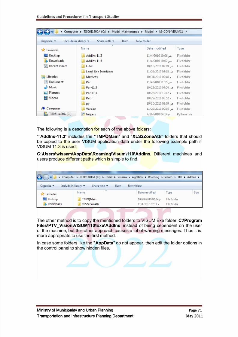
8/9/2019 TIPD Qatar Traffic Manual & Guidelines
http://slidepdf.com/reader/full/tipd-qatar-traffic-manual-guidelines 80/197
Guidelines and Procedures for Transport Studies
MMiinniissttr r yy oof f MMuunniicciippaalliittyy aanndd UUr r bbaann PPllaannnniinngg PPaaggee 7711
TTr r aannssppoor r ttaattiioonn aanndd IInnf f r r aassttr r uuccttuur r ee PPllaannnniinngg DDeeppaar r ttmmeenntt MMaayy 22001111
The following is a description for each of the above folders:
*"AddIns-11.3" includes the "TMPQMain" and "XLS2ZoneAttr " folders that shouldbe copied to the user VISUM application data under the following example path ifVISUM 11.3 is used:
C:\Users\wissam\AppData\Roaming\Visum\110\AddIns. Different machines andusers produce different paths which is simple to find.
The other method is to copy the mentioned folders to VISUM Exe folder C:\ProgramFiles\PTV_Vision\VISUM110\Exe\AddIns instead of being dependent on the userof the machine, but this other approach causes a lot of warning messages. Thus it is
more appropriate to use the first method.In case some folders like the "AppData" do not appear, then edit the folder options inthe control panel to show hidden files.
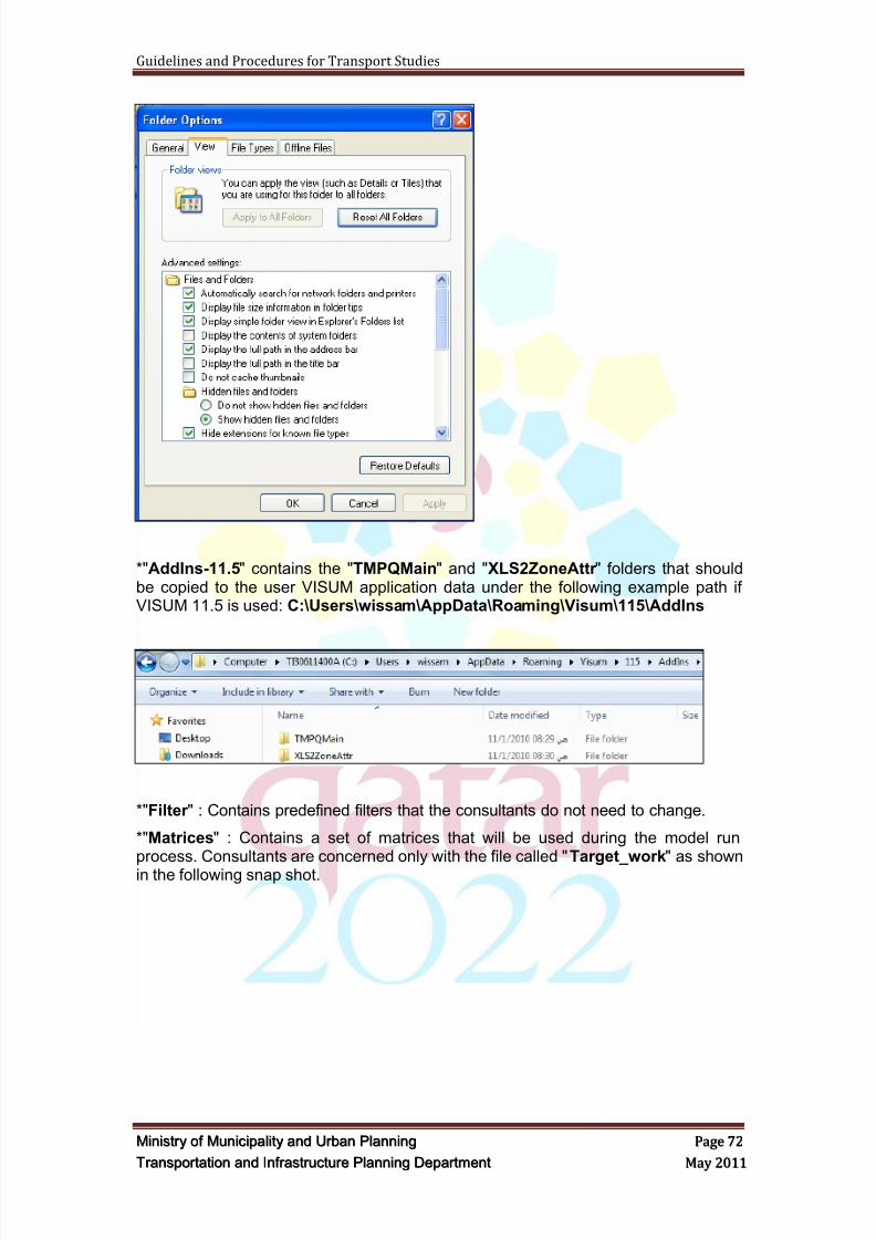
8/9/2019 TIPD Qatar Traffic Manual & Guidelines
http://slidepdf.com/reader/full/tipd-qatar-traffic-manual-guidelines 81/197
Guidelines and Procedures for Transport Studies
MMiinniissttr r yy oof f MMuunniicciippaalliittyy aanndd UUr r bbaann PPllaannnniinngg PPaaggee 7722
TTr r aannssppoor r ttaattiioonn aanndd IInnf f r r aassttr r uuccttuur r ee PPllaannnniinngg DDeeppaar r ttmmeenntt MMaayy 22001111
*"AddIns-11.5" contains the "TMPQMain" and "XLS2ZoneAttr " folders that shouldbe copied to the user VISUM application data under the following example path ifVISUM 11.5 is used: C:\Users\wissam\AppData\Roaming\Visum\115\AddIns
*"Filter " : Contains predefined filters that the consultants do not need to change.
*"Matrices" : Contains a set of matrices that will be used during the model runprocess. Consultants are concerned only with the file called "Target_work" as shown
in the following snap shot.
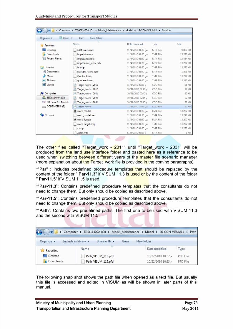
8/9/2019 TIPD Qatar Traffic Manual & Guidelines
http://slidepdf.com/reader/full/tipd-qatar-traffic-manual-guidelines 82/197
Guidelines and Procedures for Transport Studies
MMiinniissttr r yy oof f MMuunniicciippaalliittyy aanndd UUr r bbaann PPllaannnniinngg PPaaggee 7733
TTr r aannssppoor r ttaattiioonn aanndd IInnf f r r aassttr r uuccttuur r ee PPllaannnniinngg DDeeppaar r ttmmeenntt MMaayy 22001111
The other files called "Target_work - 2011" until "Target_work - 2031" will beproduced from the land use interface folder and pasted here as a reference to beused when switching between different years of the master file scenario manager(more explanation about the Target_work file is provided in the coming paragraphs).
*"Par " : Includes predefined procedure templates that should be replaced by the
content of the folder " Par-11.3" if VISUM 11.3 is used or by the content of the folder" Par-11.5" if VISUM 11.5 is used.
*"Par-11.3‖: Contains predefined procedure templates that the consultants do notneed to change them. But only should be copied as described above.
*"Par-11.5‖: Contains predefined procedure templates that the consultants do notneed to change them. But only should be copied as described above.
*"Path‖: Contains two predefined paths. The first one to be used with VISUM 11.3and the second with VISUM 11.5
The following snap shot shows the path file when opened as a text file. But usuallythis file is accessed and edited in VISUM as will be shown in later parts of this
manual.
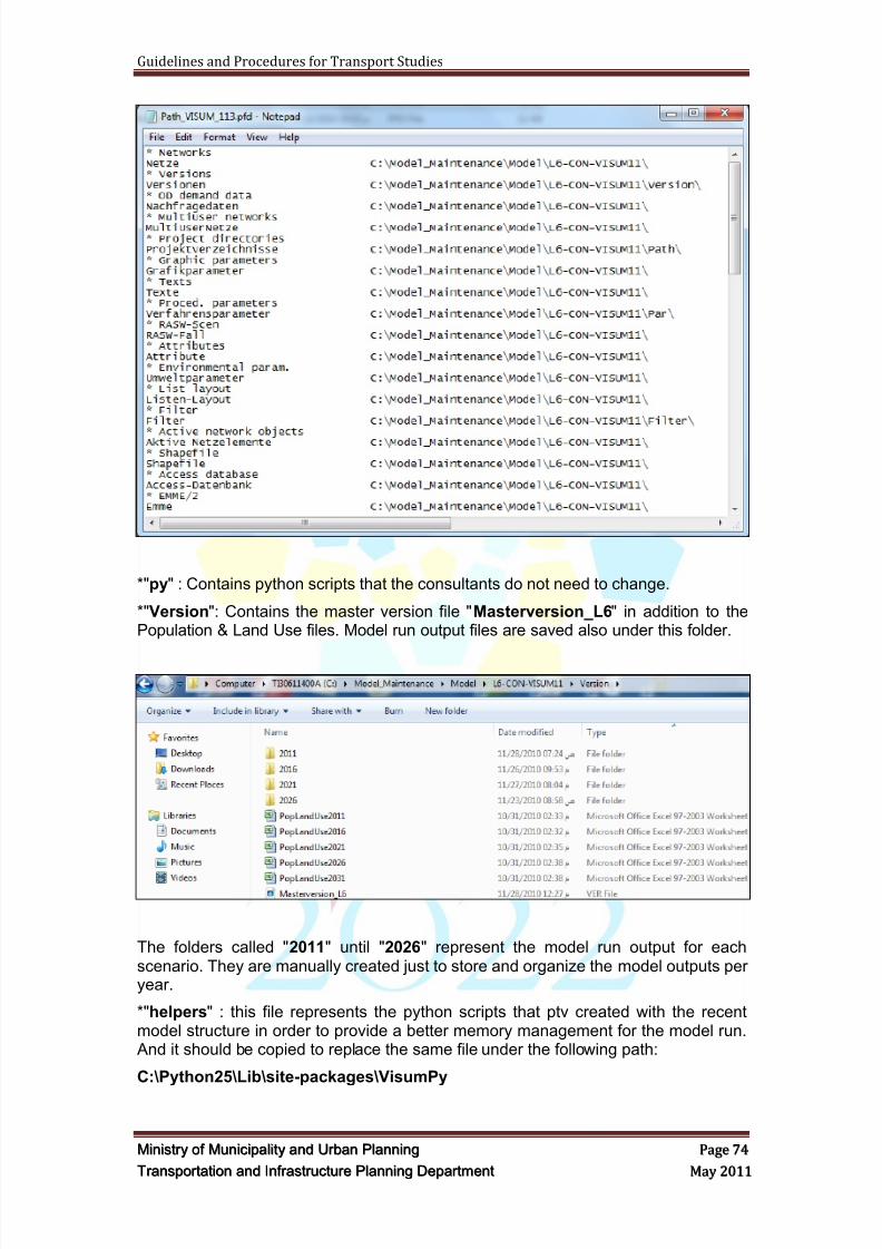
8/9/2019 TIPD Qatar Traffic Manual & Guidelines
http://slidepdf.com/reader/full/tipd-qatar-traffic-manual-guidelines 83/197
Guidelines and Procedures for Transport Studies
MMiinniissttr r yy oof f MMuunniicciippaalliittyy aanndd UUr r bbaann PPllaannnniinngg PPaaggee 7744
TTr r aannssppoor r ttaattiioonn aanndd IInnf f r r aassttr r uuccttuur r ee PPllaannnniinngg DDeeppaar r ttmmeenntt MMaayy 22001111
*"py" : Contains python scripts that the consultants do not need to change.
*"Version": Contains the master version file "Masterversion_L6" in addition to thePopulation & Land Use files. Model run output files are saved also under this folder.
The folders called "2011" until "2026" represent the model run output for eachscenario. They are manually created just to store and organize the model outputs peryear.
*"helpers" : this file represents the python scripts that ptv created with the recentmodel structure in order to provide a better memory management for the model run. And it should be copied to replace the same file under the following path:
C:\Python25\Lib\site-packages\VisumPy
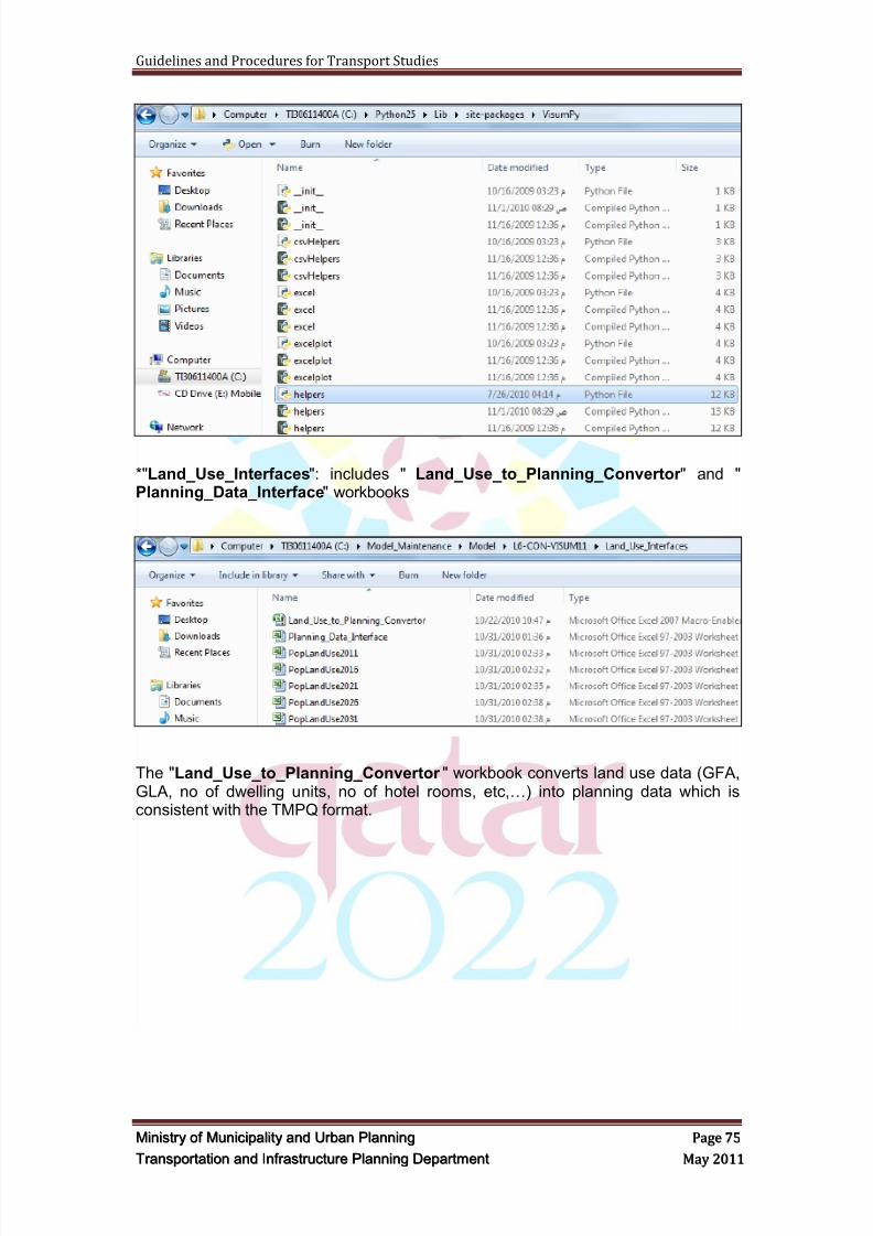
8/9/2019 TIPD Qatar Traffic Manual & Guidelines
http://slidepdf.com/reader/full/tipd-qatar-traffic-manual-guidelines 84/197
Guidelines and Procedures for Transport Studies
MMiinniissttr r yy oof f MMuunniicciippaalliittyy aanndd UUr r bbaann PPllaannnniinngg PPaaggee 7755
TTr r aannssppoor r ttaattiioonn aanndd IInnf f r r aassttr r uuccttuur r ee PPllaannnniinngg DDeeppaar r ttmmeenntt MMaayy 22001111
*"Land_Use_Interfaces": includes " Land_Use_to_Planning_Convertor " and "Planning_Data_Interface" workbooks
The "Land_Use_to_Planning_Convertor " workbook converts land use data (GFA,GLA, no of dwelling units, no of hotel rooms, etc,…) into planning data which isconsistent with the TMPQ format.
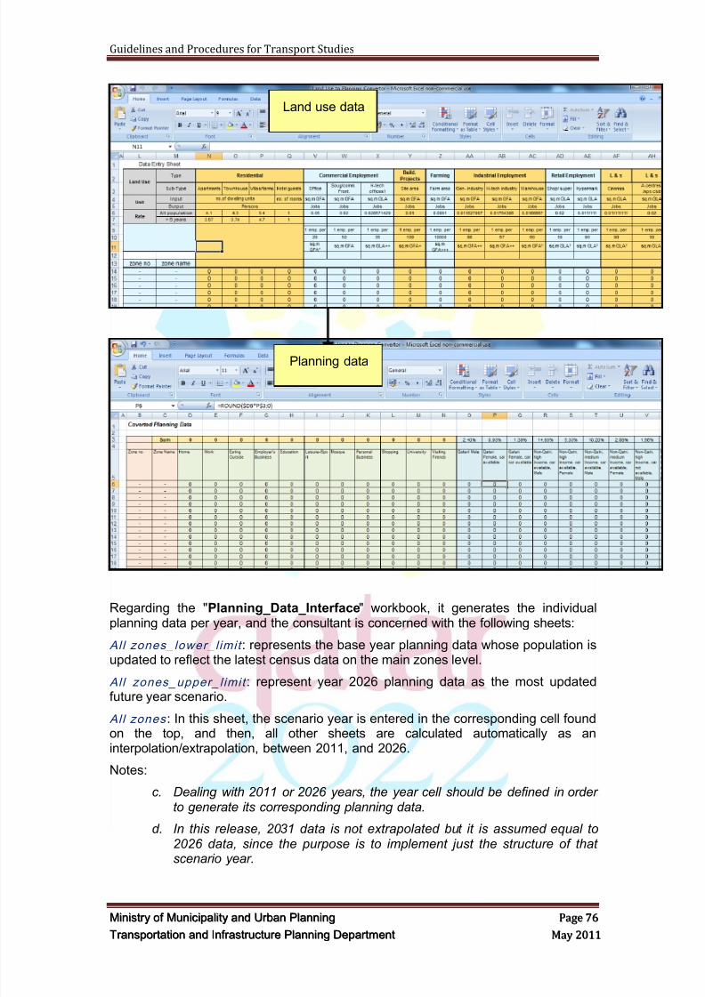
8/9/2019 TIPD Qatar Traffic Manual & Guidelines
http://slidepdf.com/reader/full/tipd-qatar-traffic-manual-guidelines 85/197
Guidelines and Procedures for Transport Studies
MMiinniissttr r yy oof f MMuunniicciippaalliittyy aanndd UUr r bbaann PPllaannnniinngg PPaaggee 7766
TTr r aannssppoor r ttaattiioonn aanndd IInnf f r r aassttr r uuccttuur r ee PPllaannnniinngg DDeeppaar r ttmmeenntt MMaayy 22001111
Regarding the "Planning_Data_Interface" workbook, it generates the individualplanning data per year, and the consultant is concerned with the following sheets:
All zones_lower_l imit : represents the base year planning data whose population isupdated to reflect the latest census data on the main zones level.
All zones_upper_l imit : represent year 2026 planning data as the most updated
future year scenario.
All zones : In this sheet, the scenario year is entered in the corresponding cell foundon the top, and then, all other sheets are calculated automatically as aninterpolation/extrapolation, between 2011, and 2026.
Notes:
c. Dealing with 2011 or 2026 years, the year cell should be defined in orderto generate its corresponding planning data.
d. In this release, 2031 data is not extrapolated but it is assumed equal to2026 data, since the purpose is to implement just the structure of thatscenario year.
Land use data
Planning data
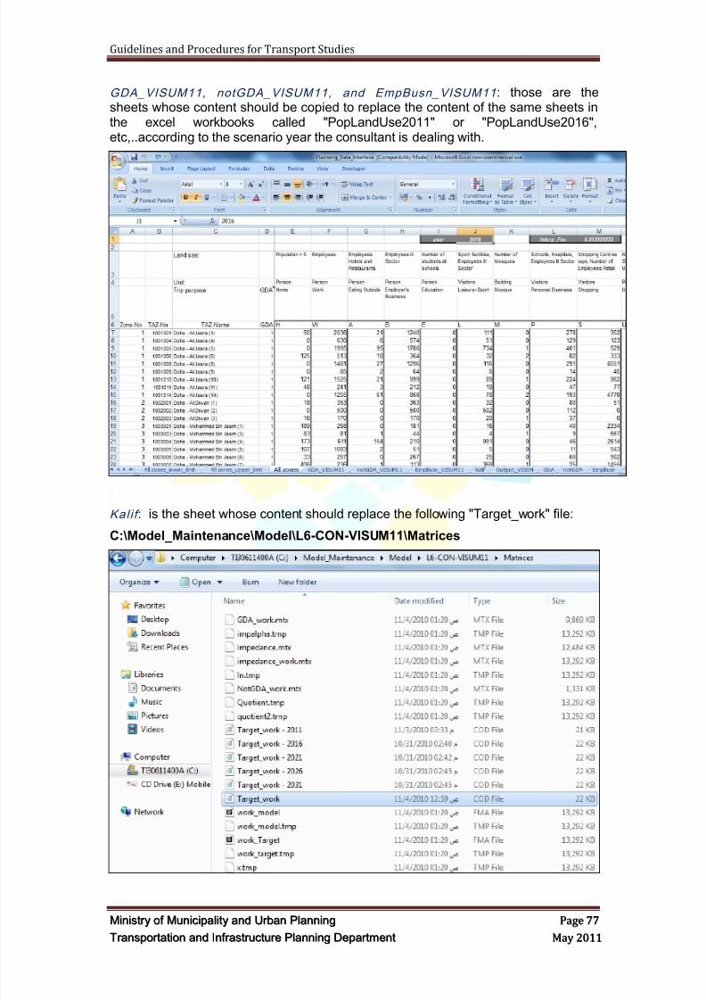
8/9/2019 TIPD Qatar Traffic Manual & Guidelines
http://slidepdf.com/reader/full/tipd-qatar-traffic-manual-guidelines 86/197
Guidelines and Procedures for Transport Studies
MMiinniissttr r yy oof f MMuunniicciippaalliittyy aanndd UUr r bbaann PPllaannnniinngg PPaaggee 7777
TTr r aannssppoor r ttaattiioonn aanndd IInnf f r r aassttr r uuccttuur r ee PPllaannnniinngg DDeeppaar r ttmmeenntt MMaayy 22001111
GDA_VISUM11, notGDA_VISUM11, and EmpBusn_VISUM11 : those are thesheets whose content should be copied to replace the content of the same sheets inthe excel workbooks called "PopLandUse2011" or "PopLandUse2016",etc,..according to the scenario year the consultant is dealing with.
Kali f : is the sheet whose content should replace the following "Target_work" file:
C:\Model_Maintenance\Model\L6-CON-VISUM11\Matrices
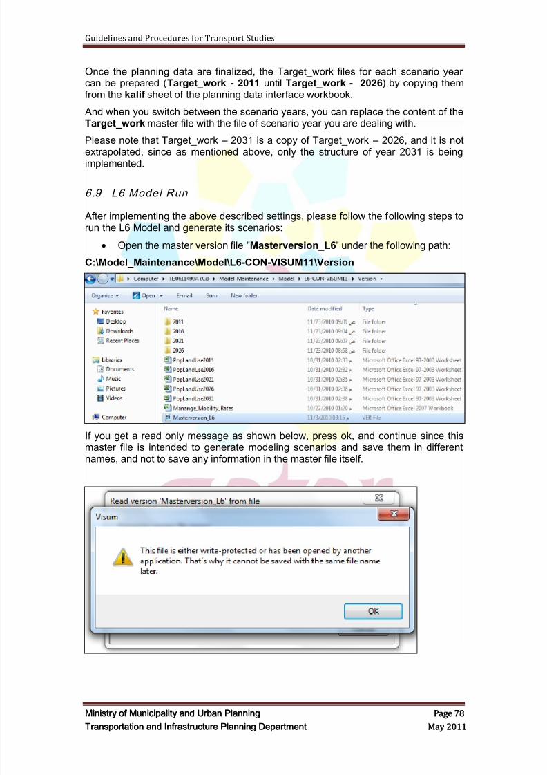
8/9/2019 TIPD Qatar Traffic Manual & Guidelines
http://slidepdf.com/reader/full/tipd-qatar-traffic-manual-guidelines 87/197
Guidelines and Procedures for Transport Studies
MMiinniissttr r yy oof f MMuunniicciippaalliittyy aanndd UUr r bbaann PPllaannnniinngg PPaaggee 7788
TTr r aannssppoor r ttaattiioonn aanndd IInnf f r r aassttr r uuccttuur r ee PPllaannnniinngg DDeeppaar r ttmmeenntt MMaayy 22001111
Once the planning data are finalized, the Target_work files for each scenario yearcan be prepared (Target_work - 2011 until Target_work - 2026) by copying themfrom the kalif sheet of the planning data interface workbook.
And when you switch between the scenario years, you can replace the content of theTarget_work master file with the file of scenario year you are dealing with.
Please note that Target_work – 2031 is a copy of Target_work – 2026, and it is notextrapolated, since as mentioned above, only the structure of year 2031 is beingimplemented.
6.9 L6 Model Run
After implementing the above described settings, please follow the following steps torun the L6 Model and generate its scenarios:
Open the master version file "Masterversion_L6" under the following path:
C:\Model_Maintenance\Model\L6-CON-VISUM11\Version
If you get a read only message as shown below, press ok, and continue since thismaster file is intended to generate modeling scenarios and save them in differentnames, and not to save any information in the master file itself.
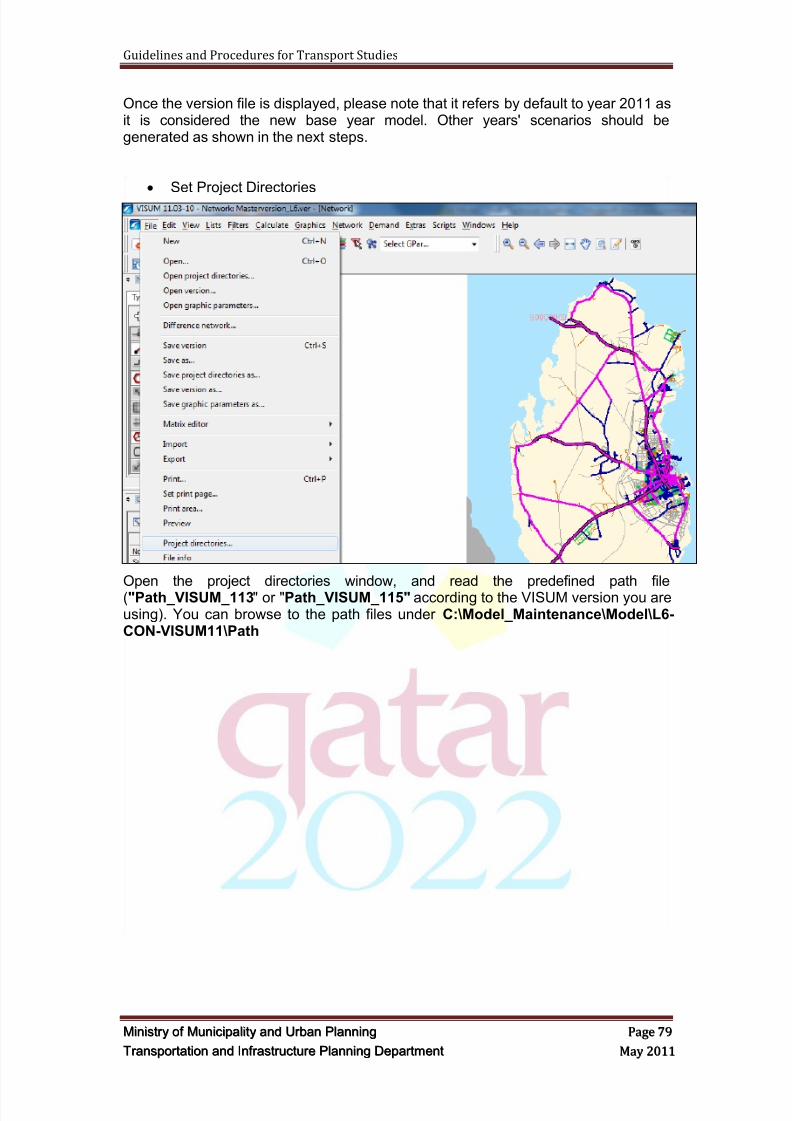
8/9/2019 TIPD Qatar Traffic Manual & Guidelines
http://slidepdf.com/reader/full/tipd-qatar-traffic-manual-guidelines 88/197
Guidelines and Procedures for Transport Studies
MMiinniissttr r yy oof f MMuunniicciippaalliittyy aanndd UUr r bbaann PPllaannnniinngg PPaaggee 7799
TTr r aannssppoor r ttaattiioonn aanndd IInnf f r r aassttr r uuccttuur r ee PPllaannnniinngg DDeeppaar r ttmmeenntt MMaayy 22001111
Once the version file is displayed, please note that it refers by default to year 2011 asit is considered the new base year model. Other years' scenarios should begenerated as shown in the next steps.
Set Project Directories
Open the project directories window, and read the predefined path file("Path_VISUM_113" or "Path_VISUM_115" according to the VISUM version you areusing). You can browse to the path files under C:\Model_Maintenance\Model\L6-CON-VISUM11\Path
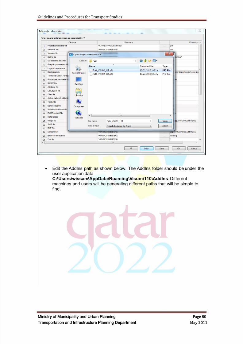
8/9/2019 TIPD Qatar Traffic Manual & Guidelines
http://slidepdf.com/reader/full/tipd-qatar-traffic-manual-guidelines 89/197
Guidelines and Procedures for Transport Studies
MMiinniissttr r yy oof f MMuunniicciippaalliittyy aanndd UUr r bbaann PPllaannnniinngg PPaaggee 8800
TTr r aannssppoor r ttaattiioonn aanndd IInnf f r r aassttr r uuccttuur r ee PPllaannnniinngg DDeeppaar r ttmmeenntt MMaayy 22001111
Edit the AddIns path as shown below. The AddIns folder should be under theuser application data
C:\Users\wissam\AppData\Roaming\Visum\110\AddIns. Differentmachines and users will be generating different paths that will be simple tofind.
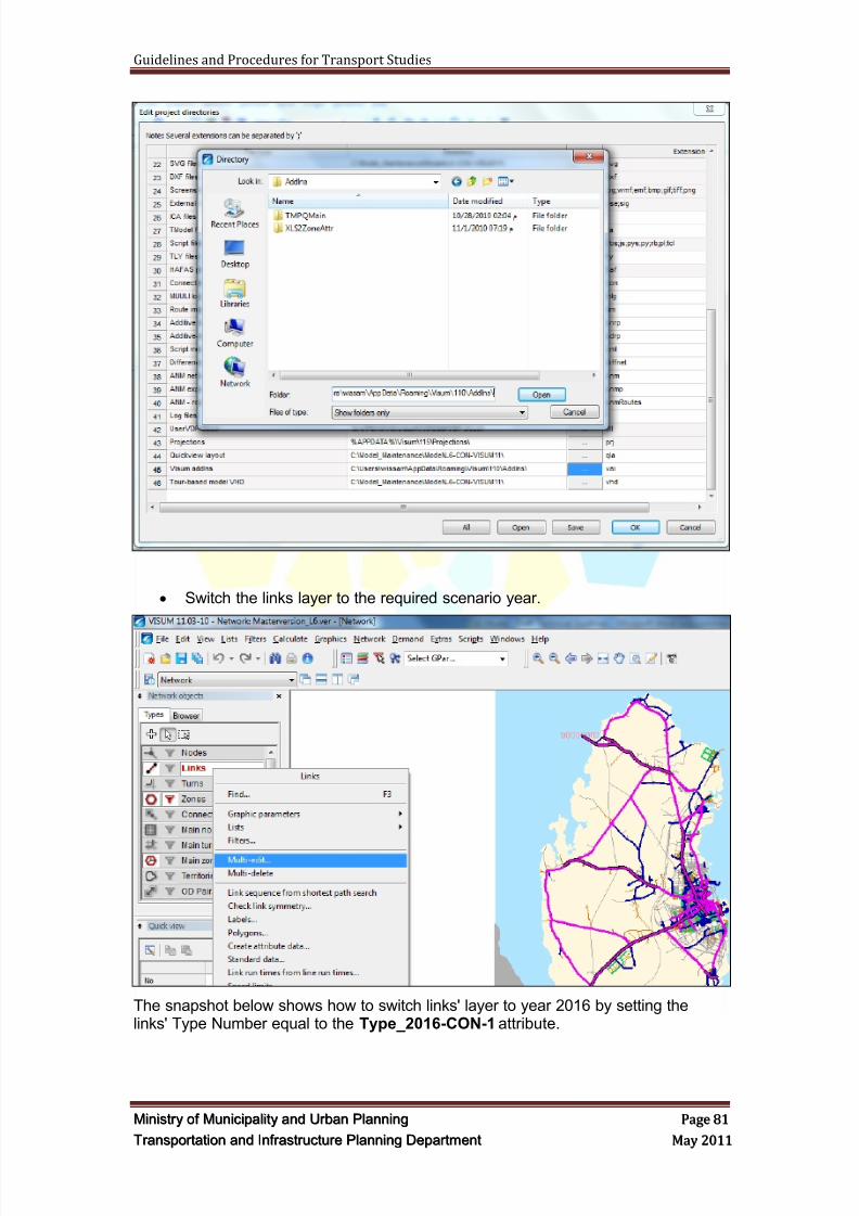
8/9/2019 TIPD Qatar Traffic Manual & Guidelines
http://slidepdf.com/reader/full/tipd-qatar-traffic-manual-guidelines 90/197
Guidelines and Procedures for Transport Studies
MMiinniissttr r yy oof f MMuunniicciippaalliittyy aanndd UUr r bbaann PPllaannnniinngg PPaaggee 8811
TTr r aannssppoor r ttaattiioonn aanndd IInnf f r r aassttr r uuccttuur r ee PPllaannnniinngg DDeeppaar r ttmmeenntt MMaayy 22001111
Switch the links layer to the required scenario year.
The snapshot below shows how to switch links' layer to year 2016 by setting thelinks' Type Number equal to the Type_2016-CON-1 attribute.
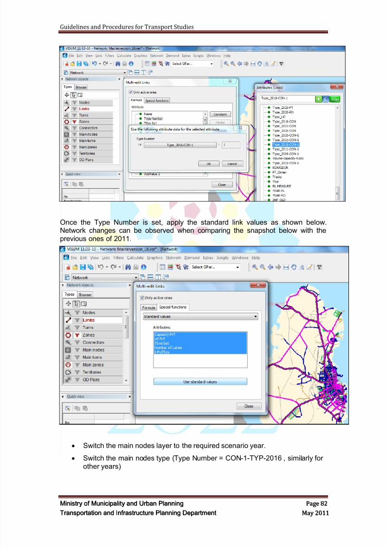
8/9/2019 TIPD Qatar Traffic Manual & Guidelines
http://slidepdf.com/reader/full/tipd-qatar-traffic-manual-guidelines 91/197
Guidelines and Procedures for Transport Studies
MMiinniissttr r yy oof f MMuunniicciippaalliittyy aanndd UUr r bbaann PPllaannnniinngg PPaaggee 8822
TTr r aannssppoor r ttaattiioonn aanndd IInnf f r r aassttr r uuccttuur r ee PPllaannnniinngg DDeeppaar r ttmmeenntt MMaayy 22001111
Once the Type Number is set, apply the standard link values as shown below.Network changes can be observed when comparing the snapshot below with theprevious ones of 2011.
Switch the main nodes layer to the required scenario year.
Switch the main nodes type (Type Number = CON-1-TYP-2016 , similarly forother years)
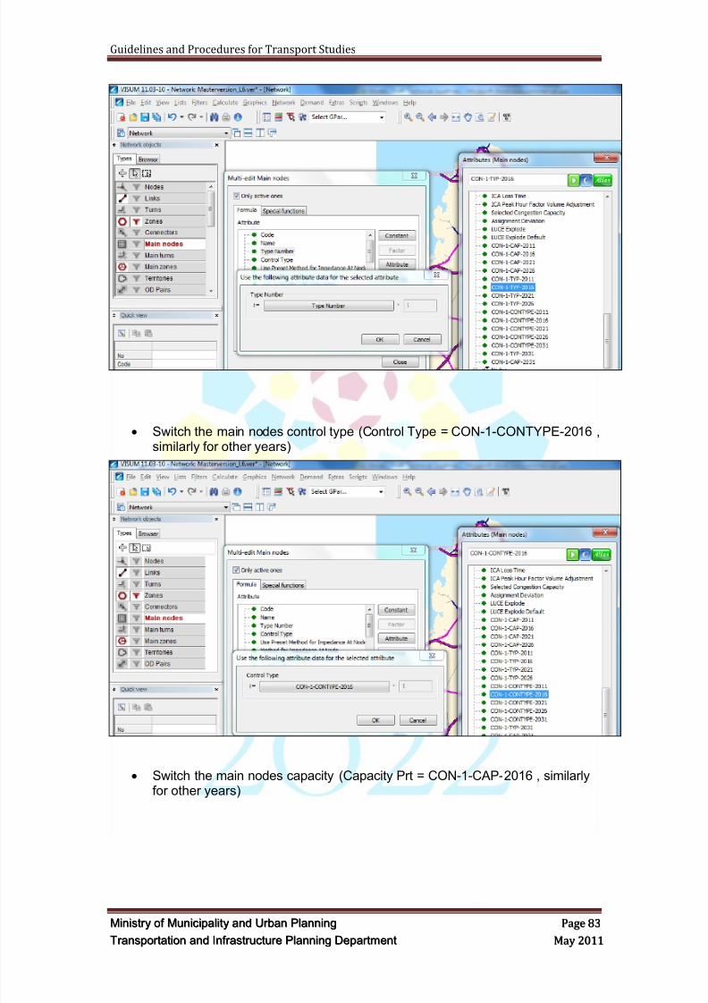
8/9/2019 TIPD Qatar Traffic Manual & Guidelines
http://slidepdf.com/reader/full/tipd-qatar-traffic-manual-guidelines 92/197
Guidelines and Procedures for Transport Studies
MMiinniissttr r yy oof f MMuunniicciippaalliittyy aanndd UUr r bbaann PPllaannnniinngg PPaaggee 8833
TTr r aannssppoor r ttaattiioonn aanndd IInnf f r r aassttr r uuccttuur r ee PPllaannnniinngg DDeeppaar r ttmmeenntt MMaayy 22001111
Switch the main nodes control type (Control Type = CON-1-CONTYPE-2016 ,similarly for other years)
Switch the main nodes capacity (Capacity Prt = CON-1-CAP-2016 , similarlyfor other years)
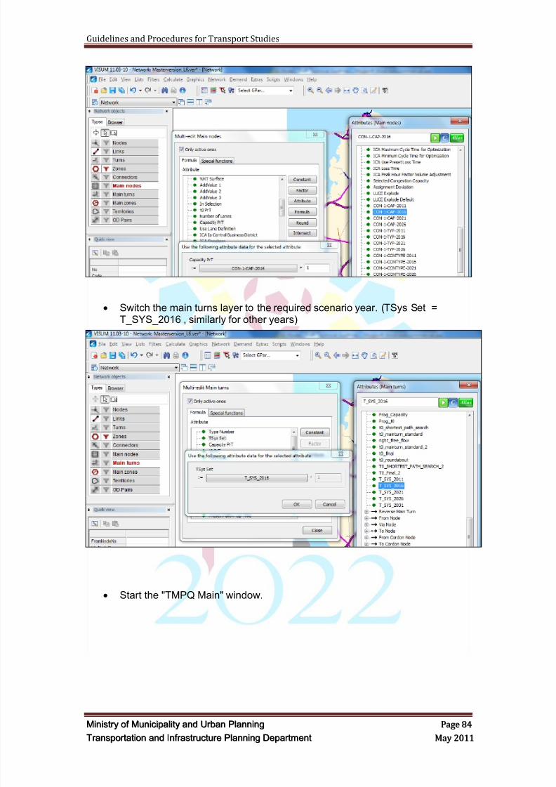
8/9/2019 TIPD Qatar Traffic Manual & Guidelines
http://slidepdf.com/reader/full/tipd-qatar-traffic-manual-guidelines 93/197
Guidelines and Procedures for Transport Studies
MMiinniissttr r yy oof f MMuunniicciippaalliittyy aanndd UUr r bbaann PPllaannnniinngg PPaaggee 8844
TTr r aannssppoor r ttaattiioonn aanndd IInnf f r r aassttr r uuccttuur r ee PPllaannnniinngg DDeeppaar r ttmmeenntt MMaayy 22001111
Switch the main turns layer to the required scenario year. (TSys Set =T_SYS_2016 , similarly for other years)
Start the "TMPQ Main" window.
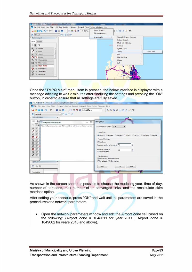
8/9/2019 TIPD Qatar Traffic Manual & Guidelines
http://slidepdf.com/reader/full/tipd-qatar-traffic-manual-guidelines 94/197
Guidelines and Procedures for Transport Studies
MMiinniissttr r yy oof f MMuunniicciippaalliittyy aanndd UUr r bbaann PPllaannnniinngg PPaaggee 8855
TTr r aannssppoor r ttaattiioonn aanndd IInnf f r r aassttr r uuccttuur r ee PPllaannnniinngg DDeeppaar r ttmmeenntt MMaayy 22001111
Once the "TMPQ Main" menu item is pressed, the below interface is displayed with a
message advising to wait 2 minutes after finalizing the settings and pressing the "OK"button, in order to ensure that all settings are fully saved.
As shown in the screen shot, it is possible to choose the modeling year, time of day,number of iterations, max number of un-converged links, and the recalculate skim
matrices option.
After setting your scenario, press "OK" and wait until all parameters are saved in theprocedures and network parameters.
Open the network parameters window and edit the Airport Zone cell based onthe following: (Airport Zone = 1048011 for year 2011 ; Airport Zone =1049002 for years 2016 and above).
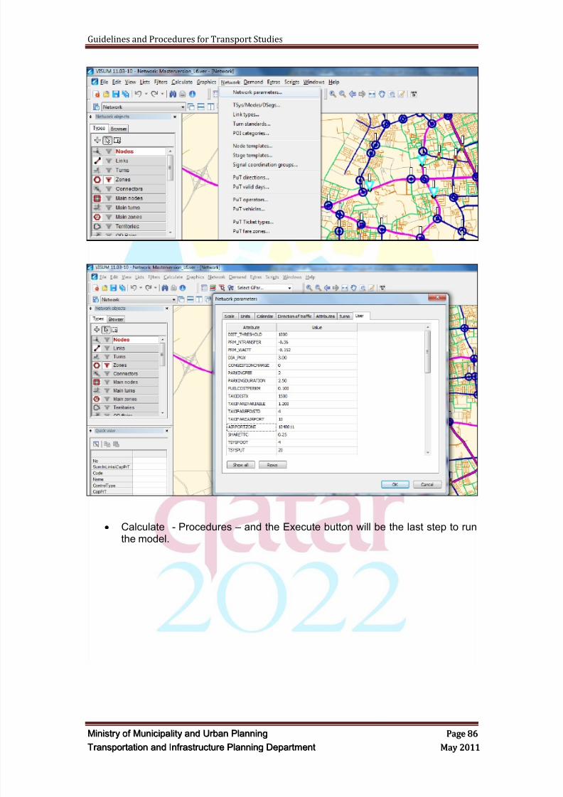
8/9/2019 TIPD Qatar Traffic Manual & Guidelines
http://slidepdf.com/reader/full/tipd-qatar-traffic-manual-guidelines 95/197
Guidelines and Procedures for Transport Studies
MMiinniissttr r yy oof f MMuunniicciippaalliittyy aanndd UUr r bbaann PPllaannnniinngg PPaaggee 8866
TTr r aannssppoor r ttaattiioonn aanndd IInnf f r r aassttr r uuccttuur r ee PPllaannnniinngg DDeeppaar r ttmmeenntt MMaayy 22001111
Calculate - Procedures – and the Execute button will be the last step to runthe model.
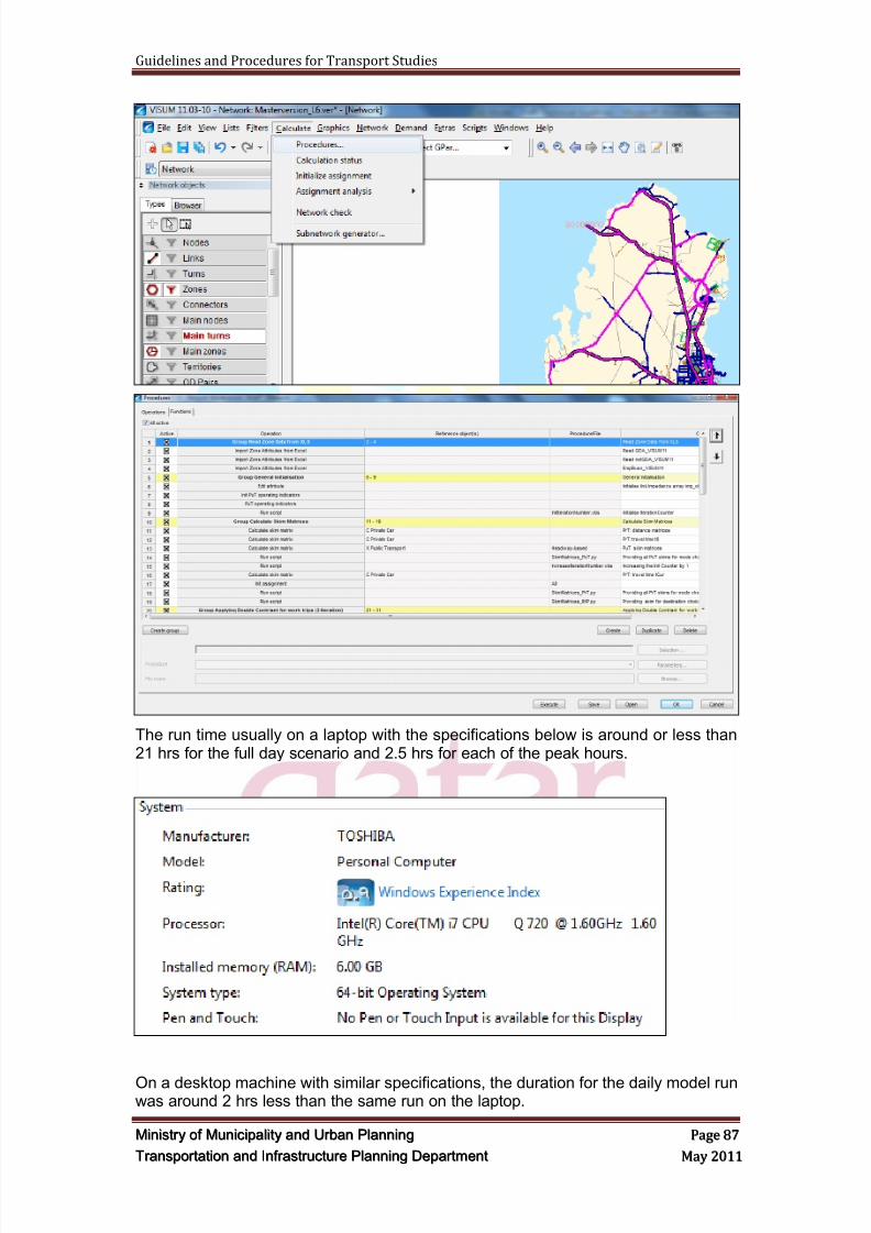
8/9/2019 TIPD Qatar Traffic Manual & Guidelines
http://slidepdf.com/reader/full/tipd-qatar-traffic-manual-guidelines 96/197
Guidelines and Procedures for Transport Studies
MMiinniissttr r yy oof f MMuunniicciippaalliittyy aanndd UUr r bbaann PPllaannnniinngg PPaaggee 8877
TTr r aannssppoor r ttaattiioonn aanndd IInnf f r r aassttr r uuccttuur r ee PPllaannnniinngg DDeeppaar r ttmmeenntt MMaayy 22001111
The run time usually on a laptop with the specifications below is around or less than21 hrs for the full day scenario and 2.5 hrs for each of the peak hours.
On a desktop machine with similar specifications, the duration for the daily model runwas around 2 hrs less than the same run on the laptop.
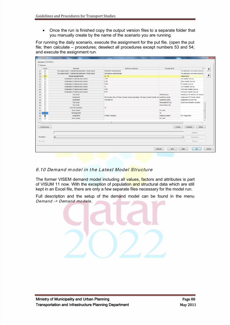
8/9/2019 TIPD Qatar Traffic Manual & Guidelines
http://slidepdf.com/reader/full/tipd-qatar-traffic-manual-guidelines 97/197
Guidelines and Procedures for Transport Studies
MMiinniissttr r yy oof f MMuunniicciippaalliittyy aanndd UUr r bbaann PPllaannnniinngg PPaaggee 8888
TTr r aannssppoor r ttaattiioonn aanndd IInnf f r r aassttr r uuccttuur r ee PPllaannnniinngg DDeeppaar r ttmmeenntt MMaayy 22001111
Once the run is finished copy the output version files to a separate folder thatyou manually create by the name of the scenario you are running.
For running the daily scenario, execute the assignment for the put file. (open the putfile; then calculate – procedures; deselect all procedures except numbers 53 and 54;and execute the assignment run.
6.10 Demand m odel in t he Latest Model Structure
The former VISEM demand model including all values, factors and attributes is partof VISUM 11 now. With the exception of population and structural data which are stillkept in an Excel file, there are only a few separate files necessary for the model run.
Full description and the setup of the demand model can be found in the menuDemand -> Demand models .
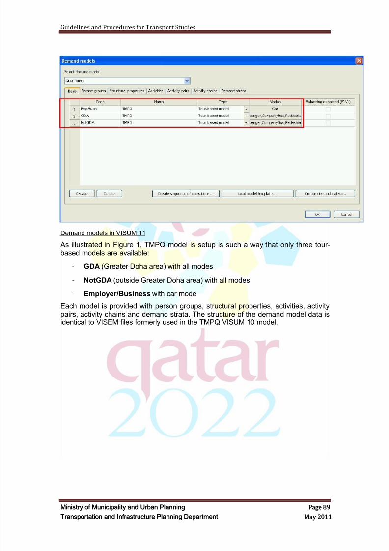
8/9/2019 TIPD Qatar Traffic Manual & Guidelines
http://slidepdf.com/reader/full/tipd-qatar-traffic-manual-guidelines 98/197
Guidelines and Procedures for Transport Studies
MMiinniissttr r yy oof f MMuunniicciippaalliittyy aanndd UUr r bbaann PPllaannnniinngg PPaaggee 8899
TTr r aannssppoor r ttaattiioonn aanndd IInnf f r r aassttr r uuccttuur r ee PPllaannnniinngg DDeeppaar r ttmmeenntt MMaayy 22001111
Demand models in VISUM 11
As illustrated in Figure 1, TMPQ model is setup is such a way that only three tour-based models are available:
- GDA (Greater Doha area) with all modes
- NotGDA (outside Greater Doha area) with all modes
- Employer/Business with car mode
Each model is provided with person groups, structural properties, activities, activitypairs, activity chains and demand strata. The structure of the demand model data isidentical to VISEM files formerly used in the TMPQ VISUM 10 model.
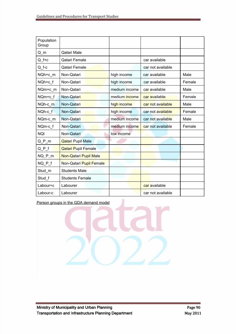
8/9/2019 TIPD Qatar Traffic Manual & Guidelines
http://slidepdf.com/reader/full/tipd-qatar-traffic-manual-guidelines 99/197
Guidelines and Procedures for Transport Studies
MMiinniissttr r yy oof f MMuunniicciippaalliittyy aanndd UUr r bbaann PPllaannnniinngg PPaaggee 9900
TTr r aannssppoor r ttaattiioonn aanndd IInnf f r r aassttr r uuccttuur r ee PPllaannnniinngg DDeeppaar r ttmmeenntt MMaayy 22001111
Population
Group
Q_m Qatari Male
Q_f+c Qatari Female car available
Q_f-c Qatari Female car not available
NQh+c_m Non-Qatari high income car available Male
NQh+c_f Non-Qatari high income car available Female
NQm+c_m Non-Qatari medium income car available Male
NQm+c_f Non-Qatari medium income car available Female
NQh-c_m Non-Qatari high income car not available Male
NQh-c_f Non-Qatari high income car not available Female
NQm-c_m Non-Qatari medium income car not available Male
NQm-c_f Non-Qatari medium income car not available Female
NQl Non-Qatari low income
Q_P_m Qatari Pupil Male
Q_P_f Qatari Pupil Female
NQ_P_m Non-Qatari Pupil Male
NQ_P_f Non-Qatari Pupil Female
Stud_m Students Male
Stud_f Students Female
Labour+c Labourer car available
Labour-c Labourer car not available
Person groups in the GDA demand model
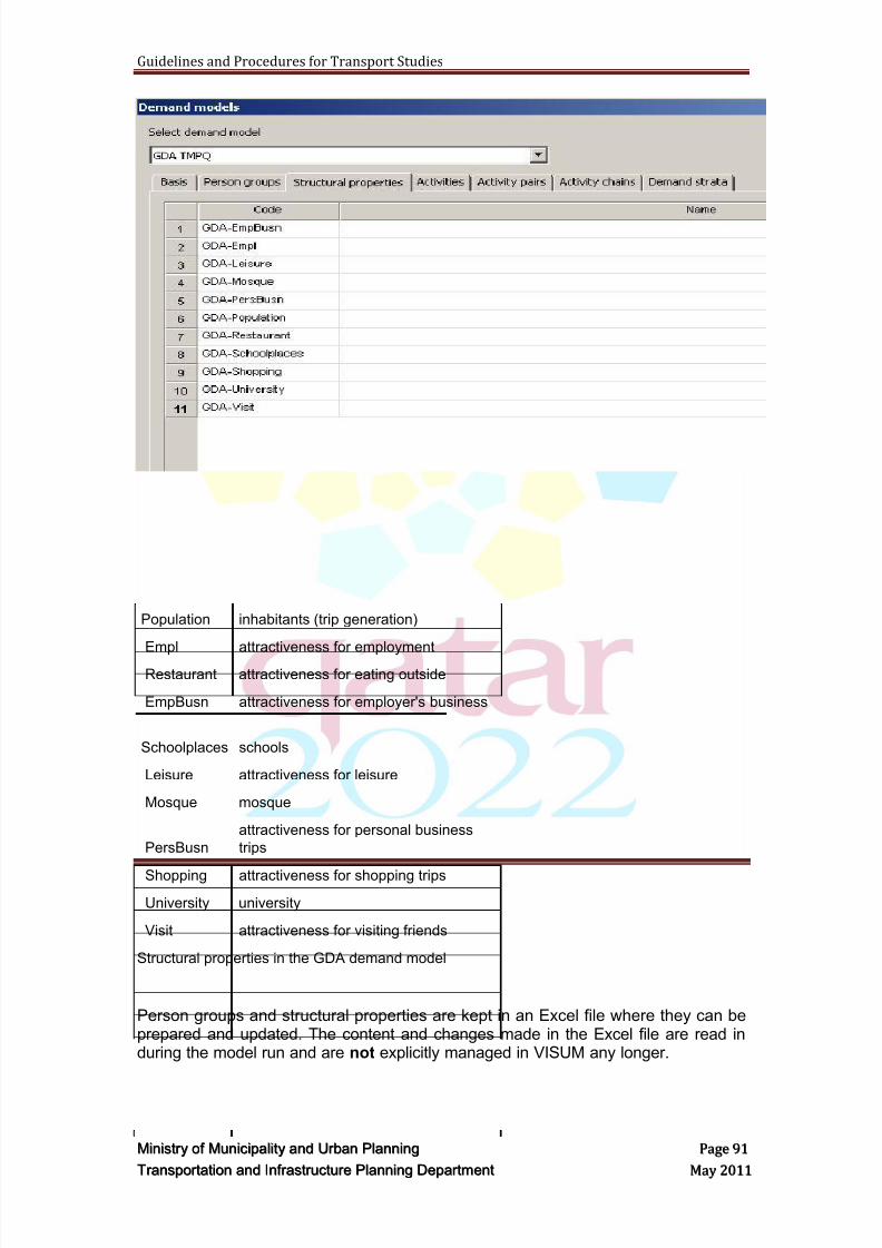
8/9/2019 TIPD Qatar Traffic Manual & Guidelines
http://slidepdf.com/reader/full/tipd-qatar-traffic-manual-guidelines 100/197
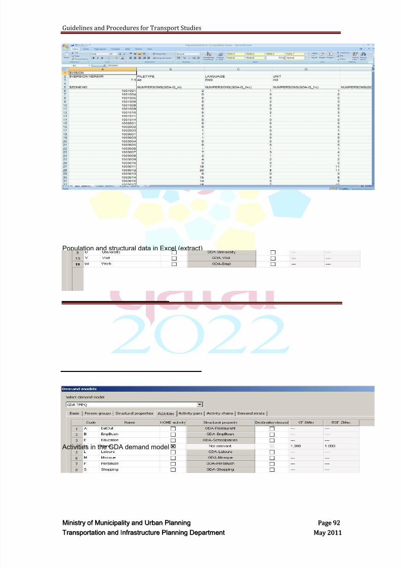
8/9/2019 TIPD Qatar Traffic Manual & Guidelines
http://slidepdf.com/reader/full/tipd-qatar-traffic-manual-guidelines 101/197
Guidelines and Procedures for Transport Studies
MMiinniissttr r yy oof f MMuunniicciippaalliittyy aanndd UUr r bbaann PPllaannnniinngg PPaaggee 9922
TTr r aannssppoor r ttaattiioonn aanndd IInnf f r r aassttr r uuccttuur r ee PPllaannnniinngg DDeeppaar r ttmmeenntt MMaayy 22001111
Population and structural data in Excel (extract)
Activities in the GDA demand model
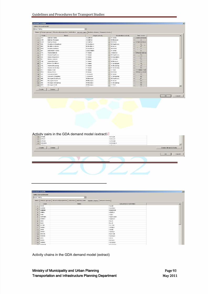
8/9/2019 TIPD Qatar Traffic Manual & Guidelines
http://slidepdf.com/reader/full/tipd-qatar-traffic-manual-guidelines 102/197
Guidelines and Procedures for Transport Studies
MMiinniissttr r yy oof f MMuunniicciippaalliittyy aanndd UUr r bbaann PPllaannnniinngg PPaaggee 9933
TTr r aannssppoor r ttaattiioonn aanndd IInnf f r r aassttr r uuccttuur r ee PPllaannnniinngg DDeeppaar r ttmmeenntt MMaayy 22001111
Activity pairs in the GDA demand model (extract)
Activity chains in the GDA demand model (extract)
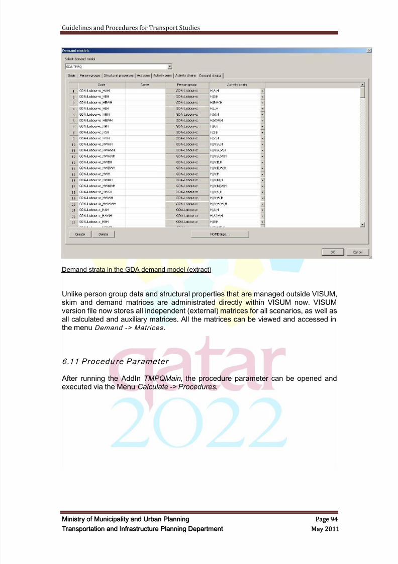
8/9/2019 TIPD Qatar Traffic Manual & Guidelines
http://slidepdf.com/reader/full/tipd-qatar-traffic-manual-guidelines 103/197
Guidelines and Procedures for Transport Studies
MMiinniissttr r yy oof f MMuunniicciippaalliittyy aanndd UUr r bbaann PPllaannnniinngg PPaaggee 9944
TTr r aannssppoor r ttaattiioonn aanndd IInnf f r r aassttr r uuccttuur r ee PPllaannnniinngg DDeeppaar r ttmmeenntt MMaayy 22001111
Demand strata in the GDA demand model (extract)
Unlike person group data and structural properties that are managed outside VISUM,skim and demand matrices are administrated directly within VISUM now. VISUMversion file now stores all independent (external) matrices for all scenarios, as well asall calculated and auxiliary matrices. All the matrices can be viewed and accessed inthe menu Demand -> Matrices .
6.11 Procedu re Parameter
After running the AddIn TMPQMain, the procedure parameter can be opened andexecuted via the Menu Calculate -> Procedures.
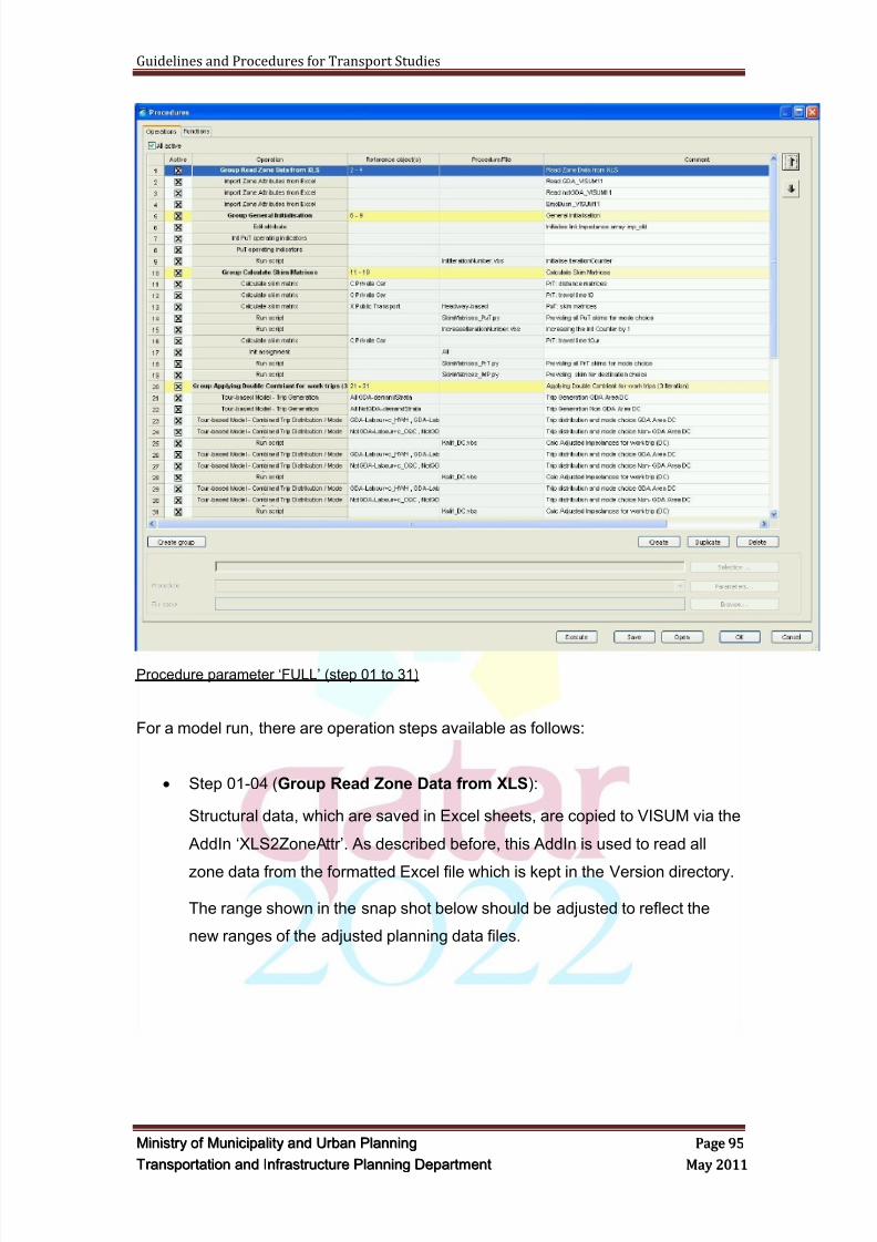
8/9/2019 TIPD Qatar Traffic Manual & Guidelines
http://slidepdf.com/reader/full/tipd-qatar-traffic-manual-guidelines 104/197
Guidelines and Procedures for Transport Studies
MMiinniissttr r yy oof f MMuunniicciippaalliittyy aanndd UUr r bbaann PPllaannnniinngg PPaaggee 9955
TTr r aannssppoor r ttaattiioonn aanndd IInnf f r r aassttr r uuccttuur r ee PPllaannnniinngg DDeeppaar r ttmmeenntt MMaayy 22001111
Procedure parameter ‗FULL‘ (step 01 to 31)
For a model run, there are operation steps available as follows:
Step 01-04 (Group Read Zone Data from XLS):
Structural data, which are saved in Excel sheets, are copied to VISUM via the
AddIn ‗XLS2ZoneAttr‘. As described before, this AddIn is used to read all
zone data from the formatted Excel file which is kept in the Version directory.
The range shown in the snap shot below should be adjusted to reflect the
new ranges of the adjusted planning data files.
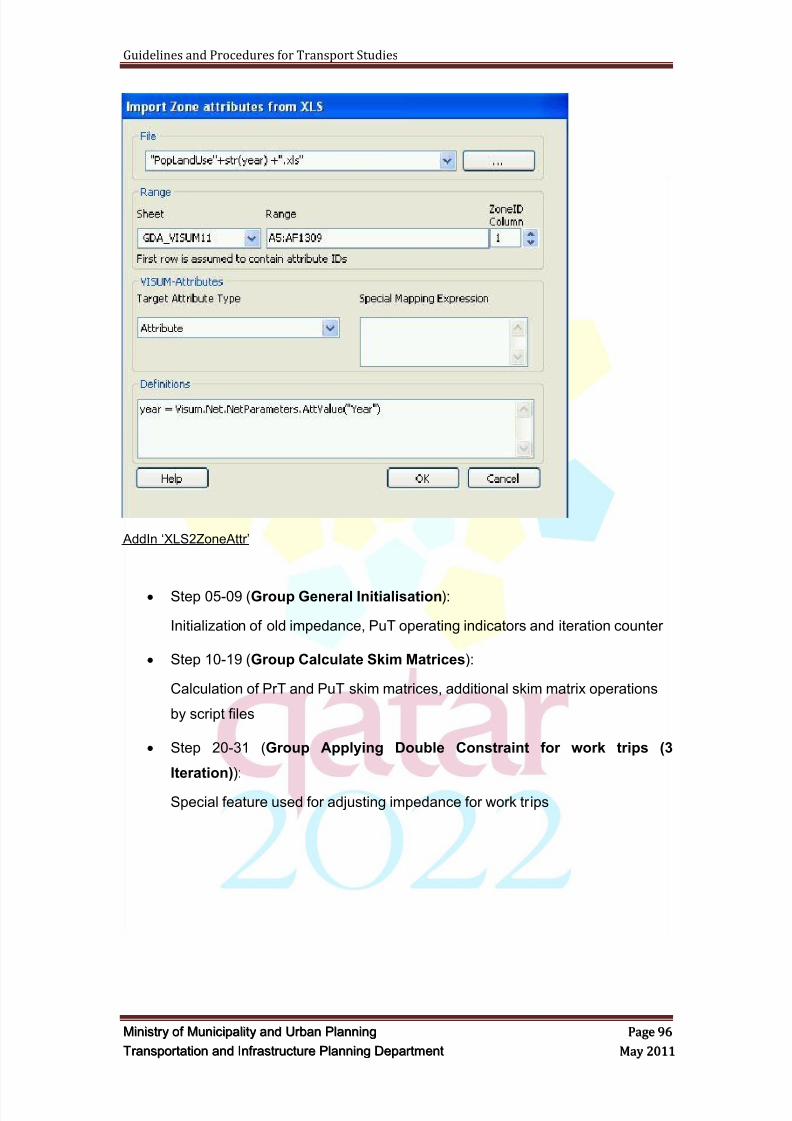
8/9/2019 TIPD Qatar Traffic Manual & Guidelines
http://slidepdf.com/reader/full/tipd-qatar-traffic-manual-guidelines 105/197
Guidelines and Procedures for Transport Studies
MMiinniissttr r yy oof f MMuunniicciippaalliittyy aanndd UUr r bbaann PPllaannnniinngg PPaaggee 9966
TTr r aannssppoor r ttaattiioonn aanndd IInnf f r r aassttr r uuccttuur r ee PPllaannnniinngg DDeeppaar r ttmmeenntt MMaayy 22001111
AddIn ‗XLS2ZoneAttr‘
Step 05-09 (Group General Initialisation):
Initialization of old impedance, PuT operating indicators and iteration counter
Step 10-19 (Group Calculate Skim Matrices):
Calculation of PrT and PuT skim matrices, additional skim matrix operations
by script files
Step 20-31 (Group Applying Double Constraint for work trips (3
Iteration)):
Special feature used for adjusting impedance for work trips
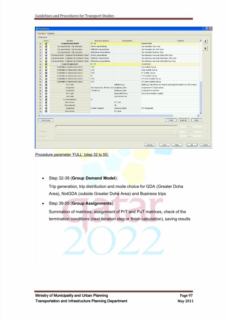
8/9/2019 TIPD Qatar Traffic Manual & Guidelines
http://slidepdf.com/reader/full/tipd-qatar-traffic-manual-guidelines 106/197
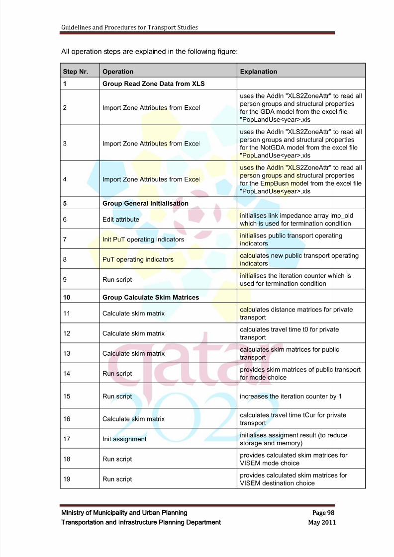
8/9/2019 TIPD Qatar Traffic Manual & Guidelines
http://slidepdf.com/reader/full/tipd-qatar-traffic-manual-guidelines 107/197
Guidelines and Procedures for Transport Studies
MMiinniissttr r yy oof f MMuunniicciippaalliittyy aanndd UUr r bbaann PPllaannnniinngg PPaaggee 9988
TTr r aannssppoor r ttaattiioonn aanndd IInnf f r r aassttr r uuccttuur r ee PPllaannnniinngg DDeeppaar r ttmmeenntt MMaayy 22001111
All operation steps are explained in the following figure:
Step Nr. Operation Explanation
1 Group Read Zone Data from XLS
2 Import Zone Attributes from Exceluses the AddIn "XLS2ZoneAttr" to read allperson groups and structural properties
for the GDA model from the excel file
"PopLandUse<year>.xls
3 Import Zone Attributes from Excel
uses the AddIn "XLS2ZoneAttr" to read all
person groups and structural properties
for the NotGDA model from the excel file
"PopLandUse<year>.xls
4 Import Zone Attributes from Excel
uses the AddIn "XLS2ZoneAttr" to read all
person groups and structural properties
for the EmpBusn model from the excel file
"PopLandUse<year>.xls
5 Group General Initialisation
6 Edit attributeinitialises link impedance array imp_old
which is used for termination condition
7 Init PuT operating indicatorsinitialises public transport operating
indicators
8 PuT operating indicatorscalculates new public transport operating
indicators
9 Run scriptinitialises the iteration counter which is
used for termination condition
10 Group Calculate Skim Matrices
11 Calculate skim matrixcalculates distance matrices for private
transport
12 Calculate skim matrixcalculates travel time t0 for private
transport
13 Calculate skim matrixcalculates skim matrices for public
transport
14 Run scriptprovides skim matrices of public transport
for mode choice
15 Run script increases the iteration counter by 1
16 Calculate skim matrixcalculates travel time tCur for private
transport
17 Init assignmentinitialises assigment result (to reduce
storage and memory)
18 Run scriptprovides calculated skim matrices for
VISEM mode choice
19 Run scriptprovides calculated skim matrices for
VISEM destination choice
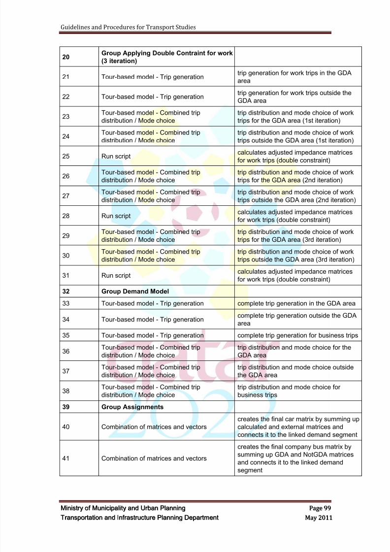
8/9/2019 TIPD Qatar Traffic Manual & Guidelines
http://slidepdf.com/reader/full/tipd-qatar-traffic-manual-guidelines 108/197
Guidelines and Procedures for Transport Studies
MMiinniissttr r yy oof f MMuunniicciippaalliittyy aanndd UUr r bbaann PPllaannnniinngg PPaaggee 9999
TTr r aannssppoor r ttaattiioonn aanndd IInnf f r r aassttr r uuccttuur r ee PPllaannnniinngg DDeeppaar r ttmmeenntt MMaayy 22001111
20Group Applying Double Contraint for work
(3 iteration)
21 Tour-based model - Trip generationtrip generation for work trips in the GDA
area
22 Tour-based model - Trip generationtrip generation for work trips outside the
GDA area
23Tour-based model - Combined trip
distribution / Mode choice
trip distribution and mode choice of work
trips for the GDA area (1st iteration)
24Tour-based model - Combined trip
distribution / Mode choice
trip distribution and mode choice of work
trips outside the GDA area (1st iteration)
25 Run scriptcalculates adjusted impedance matrices
for work trips (double constraint)
26Tour-based model - Combined trip
distribution / Mode choice
trip distribution and mode choice of work
trips for the GDA area (2nd iteration)
27 Tour-based model - Combined tripdistribution / Mode choice
trip distribution and mode choice of worktrips outside the GDA area (2nd iteration)
28 Run scriptcalculates adjusted impedance matrices
for work trips (double constraint)
29Tour-based model - Combined trip
distribution / Mode choice
trip distribution and mode choice of work
trips for the GDA area (3rd iteration)
30Tour-based model - Combined trip
distribution / Mode choice
trip distribution and mode choice of work
trips outside the GDA area (3rd iteration)
31 Run scriptcalculates adjusted impedance matrices
for work trips (double constraint)
32 Group Demand Model
33 Tour-based model - Trip generation complete trip generation in the GDA area
34 Tour-based model - Trip generationcomplete trip generation outside the GDA
area
35 Tour-based model - Trip generation complete trip generation for business trips
36Tour-based model - Combined trip
distribution / Mode choice
trip distribution and mode choice for the
GDA area
37Tour-based model - Combined trip
distribution / Mode choice
trip distribution and mode choice outside
the GDA area
38 Tour-based model - Combined tripdistribution / Mode choice
trip distribution and mode choice forbusiness trips
39 Group Assignments
40 Combination of matrices and vectors
creates the final car matrix by summing up
calculated and external matrices and
connects it to the linked demand segment
41 Combination of matrices and vectors
creates the final company bus matrix by
summing up GDA and NotGDA matrices
and connects it to the linked demand
segment
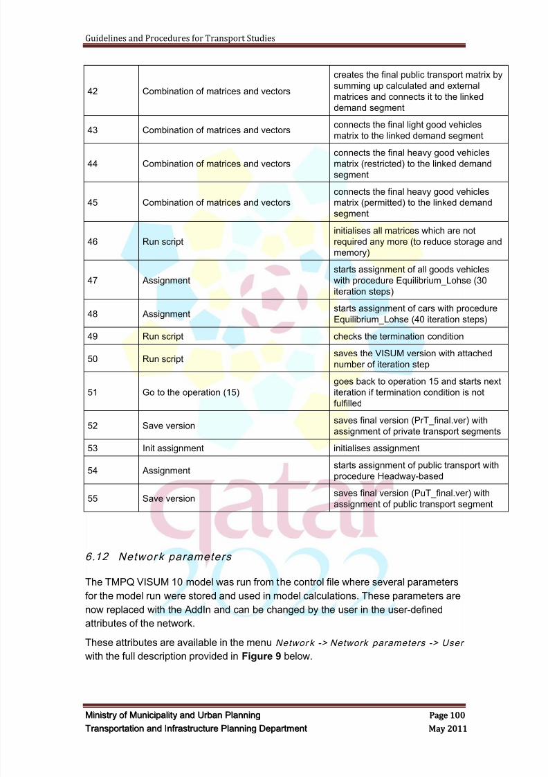
8/9/2019 TIPD Qatar Traffic Manual & Guidelines
http://slidepdf.com/reader/full/tipd-qatar-traffic-manual-guidelines 109/197
Guidelines and Procedures for Transport Studies
MMiinniissttr r yy oof f MMuunniicciippaalliittyy aanndd UUr r bbaann PPllaannnniinngg PPaaggee 110000
TTr r aannssppoor r ttaattiioonn aanndd IInnf f r r aassttr r uuccttuur r ee PPllaannnniinngg DDeeppaar r ttmmeenntt MMaayy 22001111
42 Combination of matrices and vectors
creates the final public transport matrix by
summing up calculated and external
matrices and connects it to the linked
demand segment
43 Combination of matrices and vectorsconnects the final light good vehicles
matrix to the linked demand segment
44 Combination of matrices and vectors
connects the final heavy good vehicles
matrix (restricted) to the linked demand
segment
45 Combination of matrices and vectors
connects the final heavy good vehicles
matrix (permitted) to the linked demand
segment
46 Run script
initialises all matrices which are not
required any more (to reduce storage and
memory)
47 Assignmentstarts assignment of all goods vehicleswith procedure Equilibrium_Lohse (30
iteration steps)
48 Assignmentstarts assignment of cars with procedure
Equilibrium_Lohse (40 iteration steps)
49 Run script checks the termination condition
50 Run scriptsaves the VISUM version with attached
number of iteration step
51 Go to the operation (15)
goes back to operation 15 and starts next
iteration if termination condition is not
fulfilled
52 Save versionsaves final version (PrT_final.ver) with
assignment of private transport segments
53 Init assignment initialises assignment
54 Assignmentstarts assignment of public transport with
procedure Headway-based
55 Save versionsaves final version (PuT_final.ver) with
assignment of public transport segment
6.12 Networ k parameters
The TMPQ VISUM 10 model was run from the control file where several parameters
for the model run were stored and used in model calculations. These parameters are
now replaced with the AddIn and can be changed by the user in the user-defined
attributes of the network.
These attributes are available in the menu Networ k -> Network parameters -> User
with the full description provided in Figure 9 below.
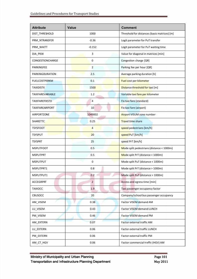
8/9/2019 TIPD Qatar Traffic Manual & Guidelines
http://slidepdf.com/reader/full/tipd-qatar-traffic-manual-guidelines 110/197
Guidelines and Procedures for Transport Studies
MMiinniissttr r yy oof f MMuunniicciippaalliittyy aanndd UUr r bbaann PPllaannnniinngg PPaaggee 110011
TTr r aannssppoor r ttaattiioonn aanndd IInnf f r r aassttr r uuccttuur r ee PPllaannnniinngg DDeeppaar r ttmmeenntt MMaayy 22001111
Attribute Value Comment
DIST_THRESHOLD 1000 Threshold for distances (basis matrices) [m]
PRM_NTRANSFER -0.36 Logit parameter for PuT transfer
PRM_WAITT -0.152 Logit parameter for PuT waiting time
DIA_PKW 3 Value for diagonal in matrices [min]
CONGESTIONCHARGE 0 Congestion charge [QR]
PARKINGFEE 2 Parking fee per hour [QR]
PARKINGDURATION 2.5 Average parking duration [h]
FUELCOSTPERKM 0.1 Fuel cost per kilometer
TAXIDISTX 1500 Distance threshold for taxi [m]
TAXIFAREVARIABLE 1.2 Variable taxi fare per kilometer
TAXIFAREFIXSTD 4 Fix taxi fare (standard)
TAXIFAREAIRPORT 10 Fix taxi fare (airport)
AIRPORTZONE 1049002 Airport VISUM zone number
SHARETTC 0.25 Travel time share
TSYSFOOT 4 speed pedestrians [km/h]
TSYSPUT 20 speed PuT [km/h]
TSYSPRT 25 speed PrT [km/h]
MSPLITFOOT 0.5 Mode split pedestrians (distance < 1000m)
MSPLITPRT 0.5 Mode split PrT (distance < 1000m)
MSPLITPUT 0 Mode split PuT (distance < 1000m)
MSPLITPRT1 0.8 Mode split PrT (distance > 1000m)
MSPLITPUT1 0.2 Mode split PuT (distance > 1000m)
ACCEGRPRT 2 Access and egress time [min]
TAXIOCC 1.9 Taxi passenger occupancy factor
CBUSOCC 20 Company/school bus passenger occupancy
AM_VISEM 0.38 Factor VISEM demand AM
LU_VISEM 0.43 Factor VISEM demand LUNCH
PM_VISEM 0.46 Factor VISEM demand PM
AM_EXTERN 0.07 Factor external traffic AM
LU_EXTERN 0.06 Factor external traffic LUNCH
PM_EXTERN 0.06 Factor external traffic PM
AM_CT_HGV 0.06 Factor commercial traffic (HGV) AM
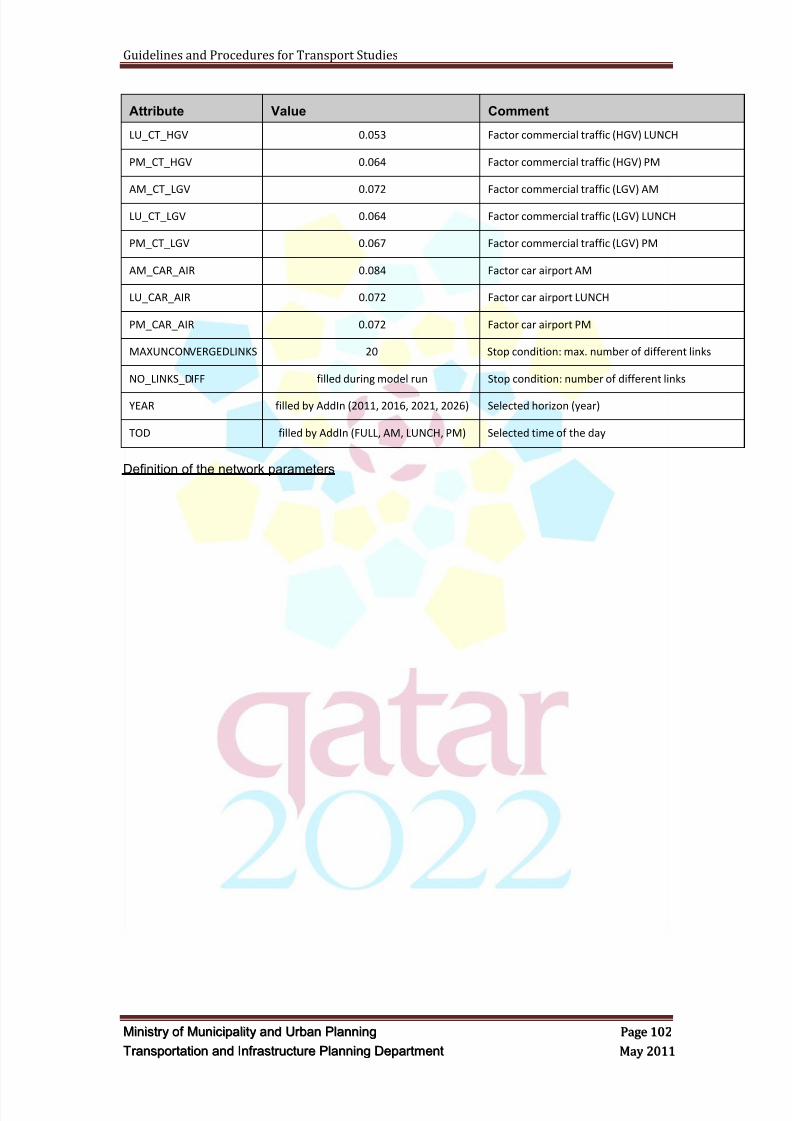
8/9/2019 TIPD Qatar Traffic Manual & Guidelines
http://slidepdf.com/reader/full/tipd-qatar-traffic-manual-guidelines 111/197
Guidelines and Procedures for Transport Studies
MMiinniissttr r yy oof f MMuunniicciippaalliittyy aanndd UUr r bbaann PPllaannnniinngg PPaaggee 110022
TTr r aannssppoor r ttaattiioonn aanndd IInnf f r r aassttr r uuccttuur r ee PPllaannnniinngg DDeeppaar r ttmmeenntt MMaayy 22001111
Attribute Value Comment
LU_CT_HGV 0.053 Factor commercial traffic (HGV) LUNCH
PM_CT_HGV 0.064 Factor commercial traffic (HGV) PM
AM_CT_LGV 0.072 Factor commercial traffic (LGV) AM
LU_CT_LGV 0.064 Factor commercial traffic (LGV) LUNCH
PM_CT_LGV 0.067 Factor commercial traffic (LGV) PM
AM_CAR_AIR 0.084 Factor car airport AM
LU_CAR_AIR 0.072 Factor car airport LUNCH
PM_CAR_AIR 0.072 Factor car airport PM
MAXUNCONVERGEDLINKS 20 Stop condition: max. number of different links
NO_LINKS_DIFF filled during model run Stop condition: number of different links
YEAR filled by AddIn (2011, 2016, 2021, 2026) Selected horizon (year)
TOD filled by AddIn (FULL, AM, LUNCH, PM) Selected time of the day
Definition of the network parameters
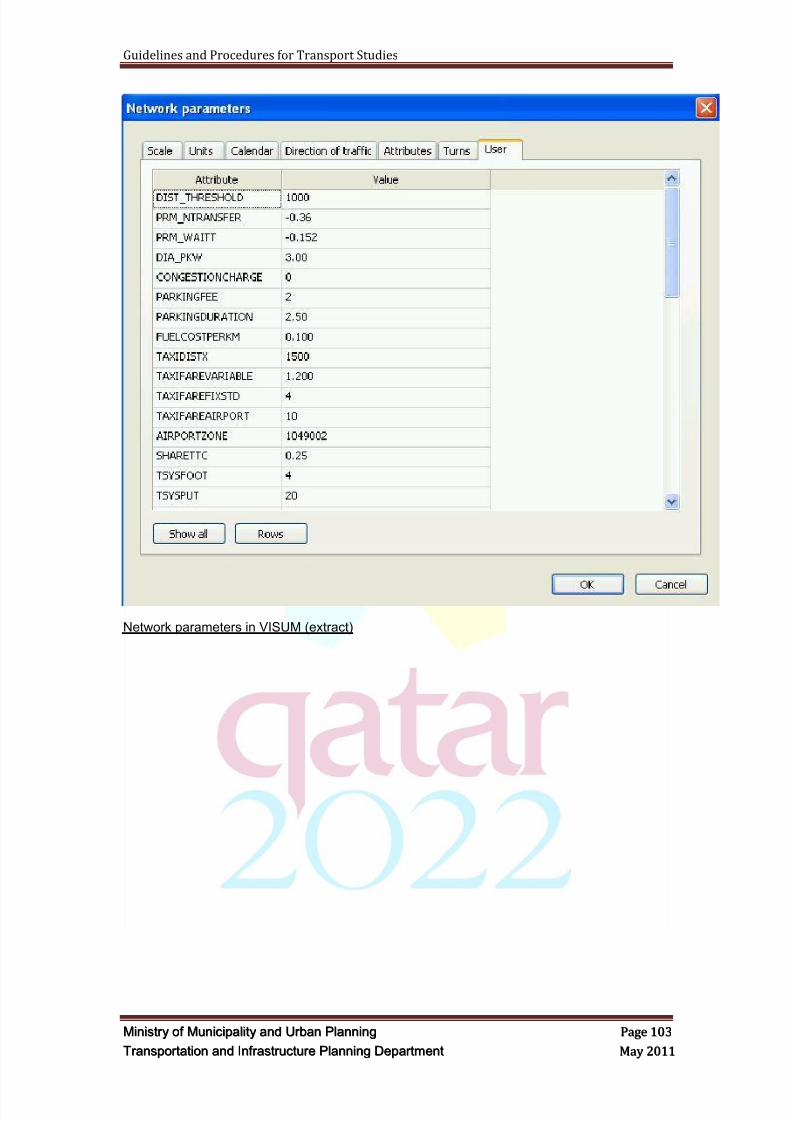
8/9/2019 TIPD Qatar Traffic Manual & Guidelines
http://slidepdf.com/reader/full/tipd-qatar-traffic-manual-guidelines 112/197
Guidelines and Procedures for Transport Studies
MMiinniissttr r yy oof f MMuunniicciippaalliittyy aanndd UUr r bbaann PPllaannnniinngg PPaaggee 110033
TTr r aannssppoor r ttaattiioonn aanndd IInnf f r r aassttr r uuccttuur r ee PPllaannnniinngg DDeeppaar r ttmmeenntt MMaayy 22001111
Network parameters in VISUM (extract)

8/9/2019 TIPD Qatar Traffic Manual & Guidelines
http://slidepdf.com/reader/full/tipd-qatar-traffic-manual-guidelines 113/197
Guidelines and Procedures for Transport Studies
MMiinniissttr r yy oof f MMuunniicciippaalliittyy aanndd UUr r bbaann PPllaannnniinngg PPaaggee 110044
TTr r aannssppoor r ttaattiioonn aanndd IInnf f r r aassttr r uuccttuur r ee PPllaannnniinngg DDeeppaar r ttmmeenntt MMaayy 22001111
6.13 Zone’s Manipulation
6.13.1 Overview
Any manipulation for the TMPQ zones will be reflected within all the master file
matrices, mainly, the predefined matrices such as the independent matrices ofairport, external, heavy and light vehicles traffic, parking fee and congestion chargingmatrices.
There are 6 independent matrices for each horizon year which is equivalent to a totalof 24 matrices for years 2011, 2016, 2021, & 2026. The ID numbers of thesematrices are (100~105 for year 2011), (110~115 for year 2016), (120~125 for year2021), and (130~135 for year 2026).
"Parking_Fee" (ID Number 227) and "Congestion_Charge" (ID Number 228) shouldalso be considered. Most of the cells in these matrices are "1" or "0". The defaultvalues are edited in case a different parking-fee or congestion-charge other than the
default values that were shown in the Network Parameters section will be applied tocertain areas.
Regarding the last three predefined matrices; ―MAE_Car‖(ID=237),‖MAE_Taxi‖(ID=238), ―MAE_CarPas‖(ID=239), the new cells referring to the additional zonesshould have a value of ―4‖.
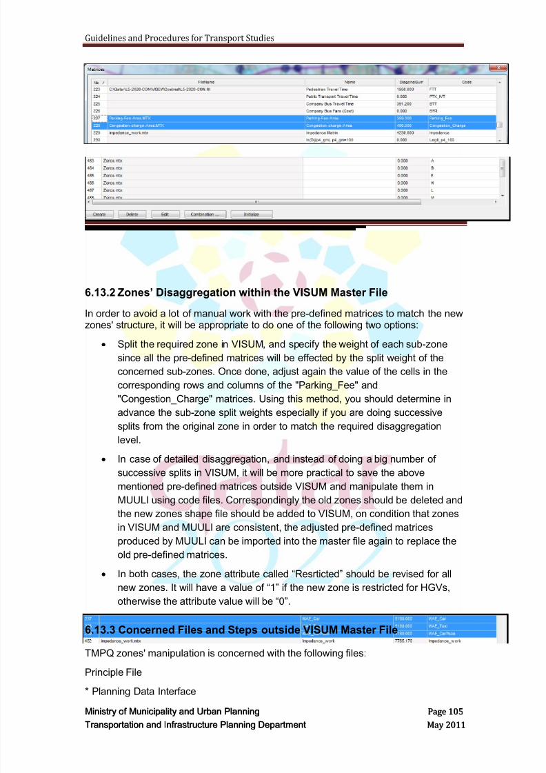
8/9/2019 TIPD Qatar Traffic Manual & Guidelines
http://slidepdf.com/reader/full/tipd-qatar-traffic-manual-guidelines 114/197
Guidelines and Procedures for Transport Studies
MMiinniissttr r yy oof f MMuunniicciippaalliittyy aanndd UUr r bbaann PPllaannnniinngg PPaaggee 110055
TTr r aannssppoor r ttaattiioonn aanndd IInnf f r r aassttr r uuccttuur r ee PPllaannnniinngg DDeeppaar r ttmmeenntt MMaayy 22001111
6.13.2 Zones’ Disaggregation within the VISUM Master File
In order to avoid a lot of manual work with the pre-defined matrices to match the newzones' structure, it will be appropriate to do one of the following two options:
Split the required zone in VISUM, and specify the weight of each sub-zone
since all the pre-defined matrices will be effected by the split weight of the
concerned sub-zones. Once done, adjust again the value of the cells in the
corresponding rows and columns of the "Parking_Fee" and
"Congestion_Charge" matrices. Using this method, you should determine in
advance the sub-zone split weights especially if you are doing successive
splits from the original zone in order to match the required disaggregation
level.
In case of detailed disaggregation, and instead of doing a big number of
successive splits in VISUM, it will be more practical to save the above
mentioned pre-defined matrices outside VISUM and manipulate them in
MUULI using code files. Correspondingly the old zones should be deleted and
the new zones shape file should be added to VISUM, on condition that zones
in VISUM and MUULI are consistent, the adjusted pre-defined matrices
produced by MUULI can be imported into the master file again to replace theold pre-defined matrices.
In both cases, the zone attribute called ―Resrticted‖ should be revised for all
new zones. It will have a value of ―1‖ if the new zone is restricted for HGVs,
otherwise the attribute value will be ―0‖.
6.13.3 Concerned Files and Steps outside VISUM Master File
TMPQ zones' manipulation is concerned with the following files:
Principle File* Planning Data Interface

8/9/2019 TIPD Qatar Traffic Manual & Guidelines
http://slidepdf.com/reader/full/tipd-qatar-traffic-manual-guidelines 115/197
Guidelines and Procedures for Transport Studies
MMiinniissttr r yy oof f MMuunniicciippaalliittyy aanndd UUr r bbaann PPllaannnniinngg PPaaggee 110066
TTr r aannssppoor r ttaattiioonn aanndd IInnf f r r aassttr r uuccttuur r ee PPllaannnniinngg DDeeppaar r ttmmeenntt MMaayy 22001111
Since the latest mode release has a master structure, then the number of zonesshould be equal in the base year model to all the horizon years. Thus anydisaggregation /aggregation of the TMPQ zones should be consistent with thisstructure. The zones that were added in the VISUM master file should be added inthe base year planning data sheet which is called "All zones_lower_limit" and the2026 planning data sheet which is called "All zones_upper_limit". Correspondingrows should be added in the next five sheets; "All zones", "GDA_VISUM11","notGDA_VISUM11", "EmpBusn_VISUM11", & "Kalif", and the formulas should bemaintained in the added rows of the last mentioned five sheets in order to reflect theadded planning data rows in the lower limit and upper limit sheets. The sorting of theplanning data based on the "TAZ-No." (Smallest ~ largest) should always be takeninto consideration while adding/ deleting zones in the planning data interface.
Once the disaggregation is done, the following outputs should be updatedcorrespondingly:
Population & Land Use Outputs: the following excel files should be updated in twoplaces whose snapshots are shown below.
* PopLandUse2011
* PopLandUse2016
* PopLandUse2021
* PopLandUse2026
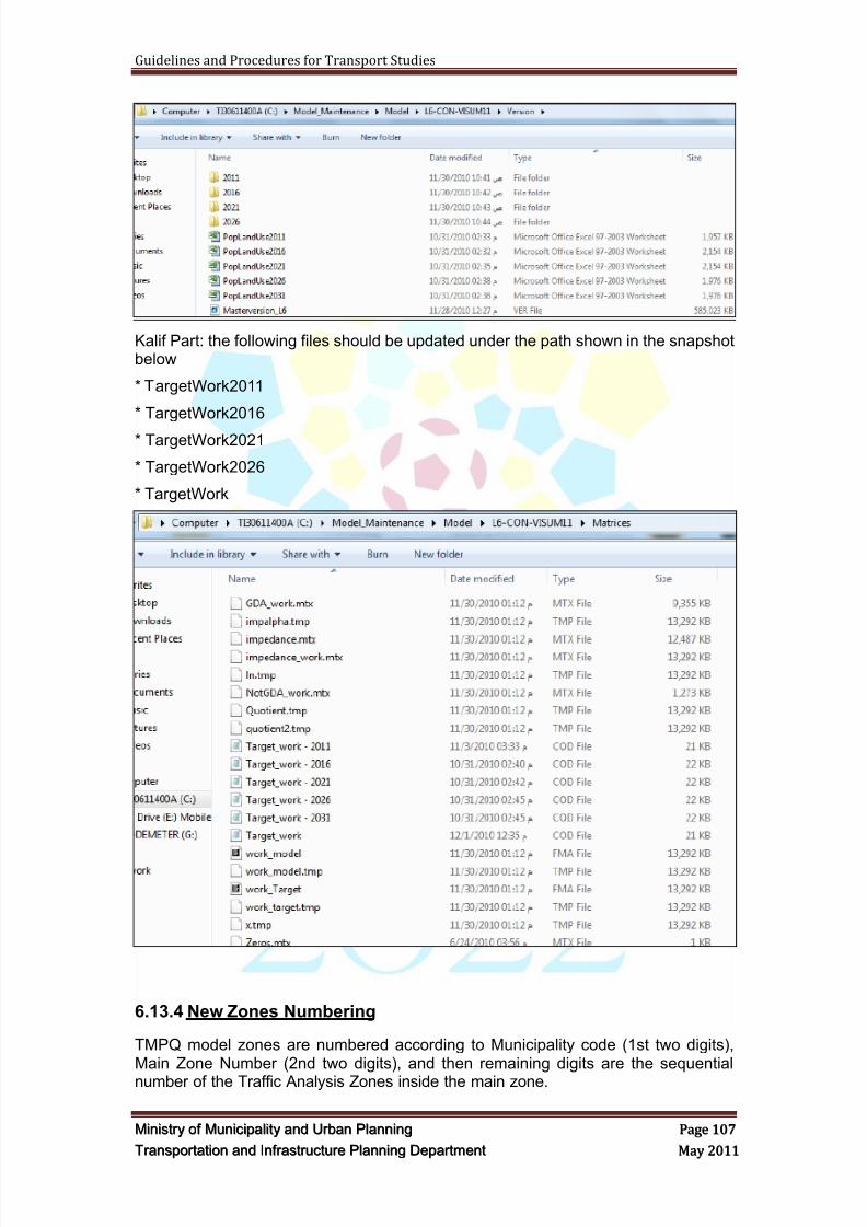
8/9/2019 TIPD Qatar Traffic Manual & Guidelines
http://slidepdf.com/reader/full/tipd-qatar-traffic-manual-guidelines 116/197
Guidelines and Procedures for Transport Studies
MMiinniissttr r yy oof f MMuunniicciippaalliittyy aanndd UUr r bbaann PPllaannnniinngg PPaaggee 110077
TTr r aannssppoor r ttaattiioonn aanndd IInnf f r r aassttr r uuccttuur r ee PPllaannnniinngg DDeeppaar r ttmmeenntt MMaayy 22001111
Kalif Part: the following files should be updated under the path shown in the snapshotbelow
* TargetWork2011
* TargetWork2016
* TargetWork2021
* TargetWork2026
* TargetWork
6.13.4 New Zones Numbering
TMPQ model zones are numbered according to Municipality code (1st two digits),Main Zone Number (2nd two digits), and then remaining digits are the sequentialnumber of the Traffic Analysis Zones inside the main zone.
8/9/2019 TIPD Qatar Traffic Manual & Guidelines
http://slidepdf.com/reader/full/tipd-qatar-traffic-manual-guidelines 117/197
Guidelines and Procedures for Transport Studies
MMiinniissttr r yy oof f MMuunniicciippaalliittyy aanndd UUr r bbaann PPllaannnniinngg PPaaggee 110088
TTr r aannssppoor r ttaattiioonn aanndd IInnf f r r aassttr r uuccttuur r ee PPllaannnniinngg DDeeppaar r ttmmeenntt MMaayy 22001111
For example: 10-01-001 (Municipality – Main Zone – Zone number) – is an existingzone number.
After adding/splitting, one of the new zone numbers will be 10-01-001-01 i.e.100100101 and so on.
6.13.5 Adjustment to the Network:
i. Study area TAZs should be disaggregated to the level of roads feeding themajor corridors in the study area in order to provide a better circulation oftraffic around the project.
ii. The polygons of all newly created zones must be drawn so that the extent oftheir boundaries can be accurately identified. MMUP would reject any networksubmitted that does not have the necessary information to verify theconsultant‘s work.
iii. All connections are to be made to internal, local and collector roads unless
access points are known.iv. For zones with more than one connector, trips are to be assigned evenly to
each connector if possible unless information on nature of developments andtheir access is known.
v. Zone connectors should be refined to a level reflecting proper and realisticaccess distribution for the study area TAZs.
vi. Connectivity between new zones‘ centroids and public transport stationsshould be re-established after conducting zones‘ disaggregation and beforere-running the model.
6.13.6 Planning Data Submission
In addition to the modelling submittals as per MMUP guidelines, the consultants arerequested to submit an aggregated version of the planning data interface which isconsistent with the interface that they received as part of the latest model release(including 1301 zones).
6.14 Model Cal ibratio n and Val idation
The purpose of this procedure is to compare the base year model demand with realfield measurements based on the data collected in the field, in order to achieve a
robust core generator that will be used in forecasting target years' trips. Thus, thecloser are the trips estimated in the base year model as a function of the encodedpopulation, the more reliable are the model projections as a function of the projectedpopulation.
The logic behind this methodology is to replicate the base year conditions in terms ofgeometry, land use details, and then search for common modules between the baseand target years, and calibrate those modules according to the base yearobservations and measurements. Then the target year forecasts will automaticallyreact to the achieved base year refinements.
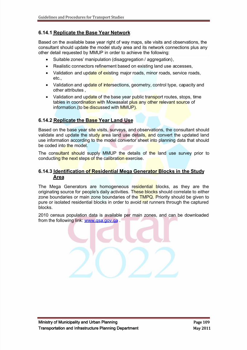
8/9/2019 TIPD Qatar Traffic Manual & Guidelines
http://slidepdf.com/reader/full/tipd-qatar-traffic-manual-guidelines 118/197
Guidelines and Procedures for Transport Studies
MMiinniissttr r yy oof f MMuunniicciippaalliittyy aanndd UUr r bbaann PPllaannnniinngg PPaaggee 110099
TTr r aannssppoor r ttaattiioonn aanndd IInnf f r r aassttr r uuccttuur r ee PPllaannnniinngg DDeeppaar r ttmmeenntt MMaayy 22001111
6.14.1 Replicate the Base Year Network
Based on the available base year right of way maps, site visits and observations, theconsultant should update the model study area and its network connections plus anyother detail requested by MMUP in order to achieve the following:
Suitable zones‘ manipulation (disaggregation / aggregation), Realistic connectors refinement based on existing land use accesses,
Validation and update of existing major roads, minor roads, service roads,etc.,
Validation and update of intersections, geometry, control type, capacity andother attributes ,
Validation and update of the base year public transport routes, stops, timetables in coordination with Mowasalat plus any other relevant source ofinformation.(to be discussed with MMUP).
6.14.2 Replicate the Base Year Land UseBased on the base year site visits, surveys, and observations, the consultant shouldvalidate and update the study area land use details, and convert the updated landuse information according to the model convertor sheet into planning data that shouldbe coded into the model.
The consultant should supply MMUP the details of the land use survey prior toconducting the next steps of the calibration exercise.
6.14.3 Identification of Residential Mega Generator Blocks in the StudyArea
The Mega Generators are homogeneous residential blocks, as they are theoriginating source for people‘s daily activities. These blocks should correlate to eitherzone boundaries or main zone boundaries of the TMPQ. Priority should be given topure or isolated residential blocks in order to avoid rat runners through the capturedblocks.
2010 census population data is available per main zones, and can be downloadedfrom the following link: www.qsa.gov.qa .
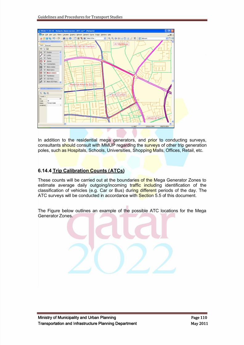
8/9/2019 TIPD Qatar Traffic Manual & Guidelines
http://slidepdf.com/reader/full/tipd-qatar-traffic-manual-guidelines 119/197
Guidelines and Procedures for Transport Studies
MMiinniissttr r yy oof f MMuunniicciippaalliittyy aanndd UUr r bbaann PPllaannnniinngg PPaaggee 111100
TTr r aannssppoor r ttaattiioonn aanndd IInnf f r r aassttr r uuccttuur r ee PPllaannnniinngg DDeeppaar r ttmmeenntt MMaayy 22001111
In addition to the residential mega generators, and prior to conducting surveys,consultants should consult with MMUP regarding the surveys of other trip generationpoles, such as Hospitals, Schools, Universities, Shopping Malls, Offices, Retail, etc.
6.14.4 Trip Calibration Counts (ATCs)
These counts will be carried out at the boundaries of the Mega Generator Zones toestimate average daily outgoing/incoming traffic including identification of theclassification of vehicles (e.g. Car or Bus) during different periods of the day. The ATC surveys will be conducted in accordance with Section 5.5 of this document.
The Figure below outlines an example of the possible ATC locations for the MegaGenerator Zones.
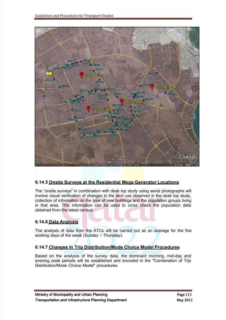
8/9/2019 TIPD Qatar Traffic Manual & Guidelines
http://slidepdf.com/reader/full/tipd-qatar-traffic-manual-guidelines 120/197
Guidelines and Procedures for Transport Studies
MMiinniissttr r yy oof f MMuunniicciippaalliittyy aanndd UUr r bbaann PPllaannnniinngg PPaaggee 111111
TTr r aannssppoor r ttaattiioonn aanndd IInnf f r r aassttr r uuccttuur r ee PPllaannnniinngg DDeeppaar r ttmmeenntt MMaayy 22001111
6.14.5 Onsite Surveys at the Residential Mega Generator Locations
The ―onsite surveys‖ in combination with desk top study using aerial photographs willinvolve visual verification of changes to the land use observed in the desk top study,collection of information on the type of new buildings and the population groups livingin that area. This information can be used to cross check the population dataobtained from the latest census.
6.14.6 Data Analysis
The analysis of data from the ATCs will be carried out as an average for the fiveworking days of the week (Sunday ~ Thursday).
6.14.7 Changes in Trip Distribution/Mode Choice Model Procedures
Based on the analysis of the survey data, the dominant morning, mid-day andevening peak periods will be established and encoded in the "Combination of TripDistribution/Mode Choice Model" procedures.
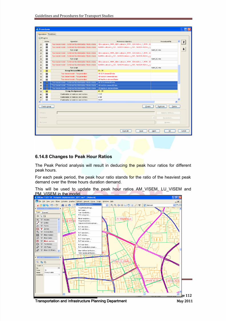
8/9/2019 TIPD Qatar Traffic Manual & Guidelines
http://slidepdf.com/reader/full/tipd-qatar-traffic-manual-guidelines 121/197
Guidelines and Procedures for Transport Studies
MMiinniissttr r yy oof f MMuunniicciippaalliittyy aanndd UUr r bbaann PPllaannnniinngg PPaaggee 111122
TTr r aannssppoor r ttaattiioonn aanndd IInnf f r r aassttr r uuccttuur r ee PPllaannnniinngg DDeeppaar r ttmmeenntt MMaayy 22001111
6.14.8 Changes to Peak Hour Ratios
The Peak Period analysis will result in deducing the peak hour ratios for different
peak hours.
For each peak period, the peak hour ratio stands for the ratio of the heaviest peakdemand over the three hours duration demand.
This will be used to update the peak hour ratios AM_VISEM, LU_VISEM andPM_VISEM in the model.
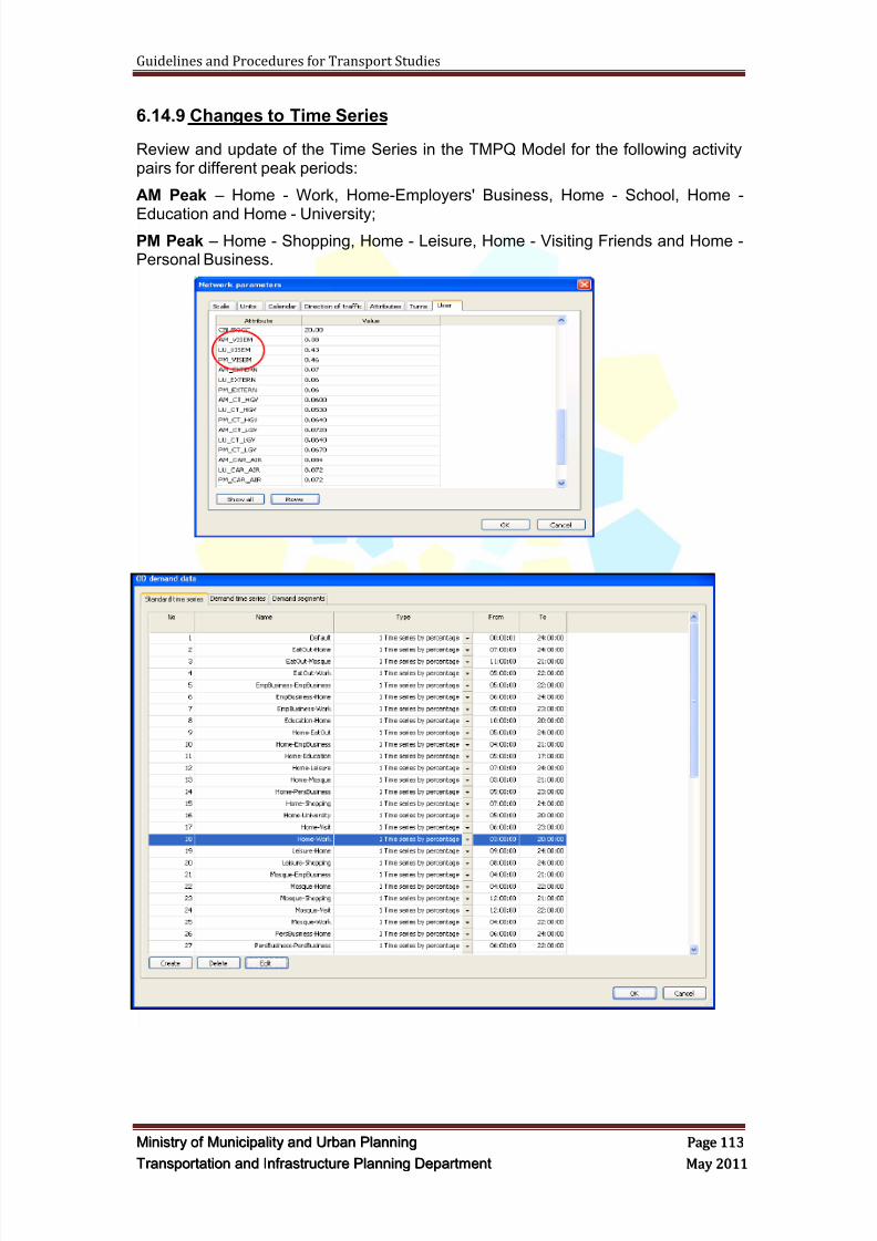
8/9/2019 TIPD Qatar Traffic Manual & Guidelines
http://slidepdf.com/reader/full/tipd-qatar-traffic-manual-guidelines 122/197
Guidelines and Procedures for Transport Studies
MMiinniissttr r yy oof f MMuunniicciippaalliittyy aanndd UUr r bbaann PPllaannnniinngg PPaaggee 111133
TTr r aannssppoor r ttaattiioonn aanndd IInnf f r r aassttr r uuccttuur r ee PPllaannnniinngg DDeeppaar r ttmmeenntt MMaayy 22001111
6.14.9 Changes to Time Series
Review and update of the Time Series in the TMPQ Model for the following activitypairs for different peak periods:
AM Peak – Home - Work, Home-Employers' Business, Home - School, Home -
Education and Home - University;PM Peak – Home - Shopping, Home - Leisure, Home - Visiting Friends and Home -Personal Business.
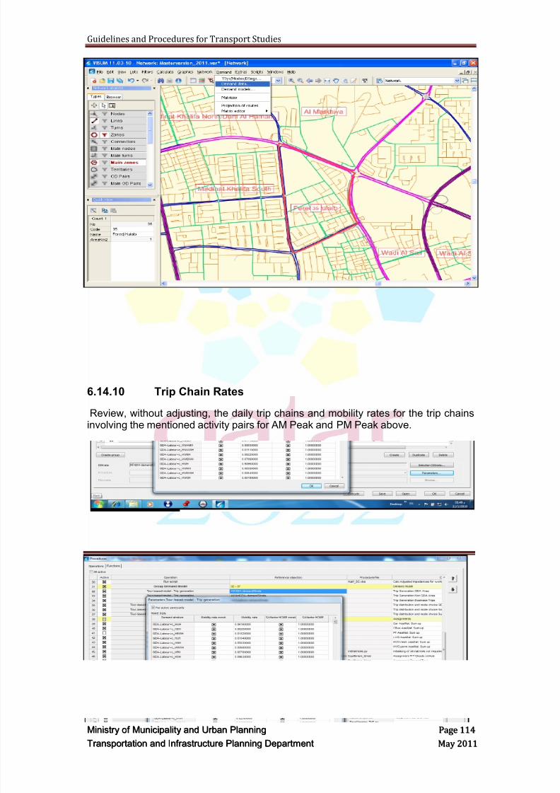
8/9/2019 TIPD Qatar Traffic Manual & Guidelines
http://slidepdf.com/reader/full/tipd-qatar-traffic-manual-guidelines 123/197
Guidelines and Procedures for Transport Studies
MMiinniissttr r yy oof f MMuunniicciippaalliittyy aanndd UUr r bbaann PPllaannnniinngg PPaaggee 111144
TTr r aannssppoor r ttaattiioonn aanndd IInnf f r r aassttr r uuccttuur r ee PPllaannnniinngg DDeeppaar r ttmmeenntt MMaayy 22001111
6.14.10 Trip Chain Rates
Review, without adjusting, the daily trip chains and mobility rates for the trip chainsinvolving the mentioned activity pairs for AM Peak and PM Peak above.
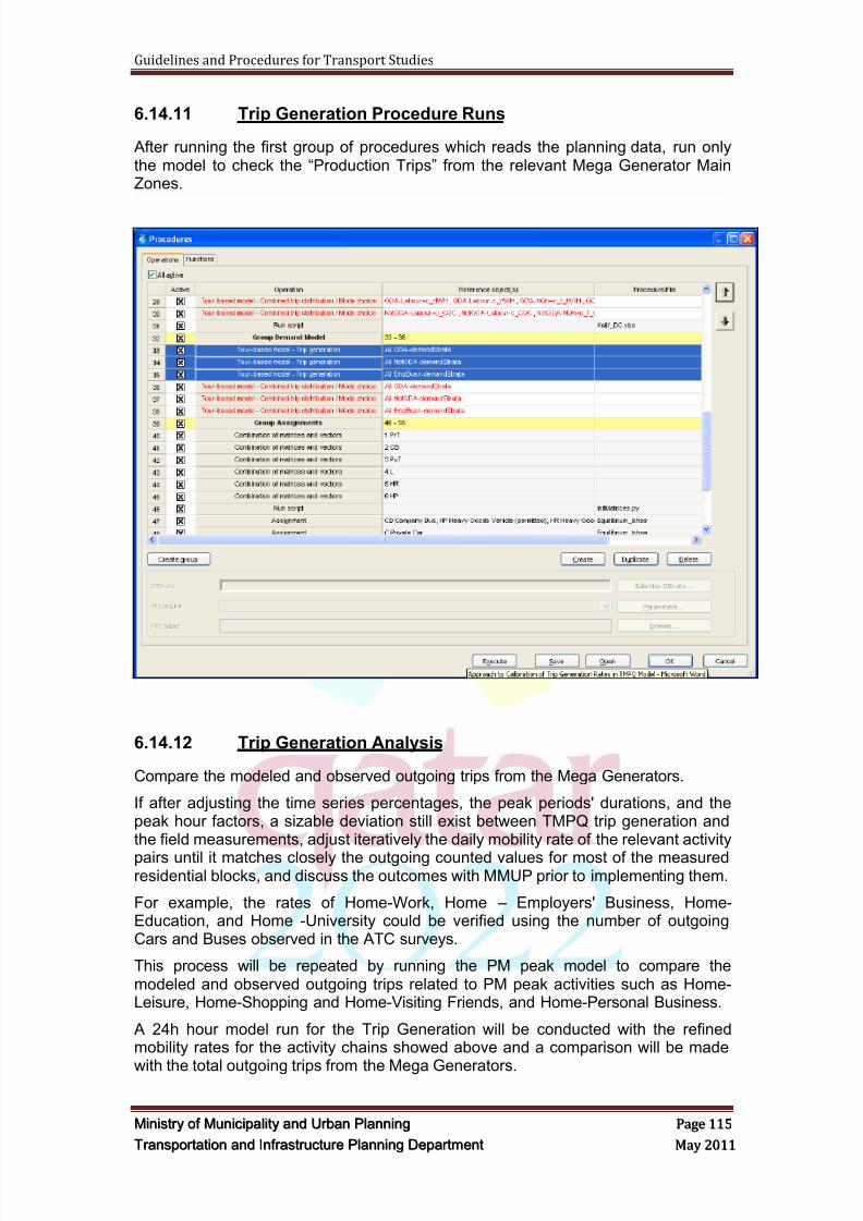
8/9/2019 TIPD Qatar Traffic Manual & Guidelines
http://slidepdf.com/reader/full/tipd-qatar-traffic-manual-guidelines 124/197
Guidelines and Procedures for Transport Studies
MMiinniissttr r yy oof f MMuunniicciippaalliittyy aanndd UUr r bbaann PPllaannnniinngg PPaaggee 111155
TTr r aannssppoor r ttaattiioonn aanndd IInnf f r r aassttr r uuccttuur r ee PPllaannnniinngg DDeeppaar r ttmmeenntt MMaayy 22001111
6.14.11 Trip Generation Procedure Runs
After running the first group of procedures which reads the planning data, run onlythe model to check the ―Production Trips‖ from the relevant Mega Generator MainZones.
6.14.12 Trip Generation Analysis
Compare the modeled and observed outgoing trips from the Mega Generators.
If after adjusting the time series percentages, the peak periods' durations, and thepeak hour factors, a sizable deviation still exist between TMPQ trip generation andthe field measurements, adjust iteratively the daily mobility rate of the relevant activity
pairs until it matches closely the outgoing counted values for most of the measuredresidential blocks, and discuss the outcomes with MMUP prior to implementing them.
For example, the rates of Home-Work, Home – Employers' Business, Home-Education, and Home -University could be verified using the number of outgoingCars and Buses observed in the ATC surveys.
This process will be repeated by running the PM peak model to compare themodeled and observed outgoing trips related to PM peak activities such as Home-Leisure, Home-Shopping and Home-Visiting Friends, and Home-Personal Business.
A 24h hour model run for the Trip Generation will be conducted with the refinedmobility rates for the activity chains showed above and a comparison will be made
with the total outgoing trips from the Mega Generators.
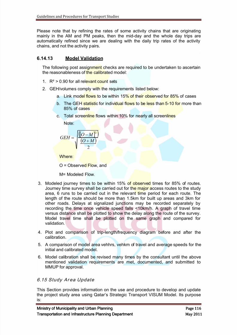
8/9/2019 TIPD Qatar Traffic Manual & Guidelines
http://slidepdf.com/reader/full/tipd-qatar-traffic-manual-guidelines 125/197
Guidelines and Procedures for Transport Studies
MMiinniissttr r yy oof f MMuunniicciippaalliittyy aanndd UUr r bbaann PPllaannnniinngg PPaaggee 111166
TTr r aannssppoor r ttaattiioonn aanndd IInnf f r r aassttr r uuccttuur r ee PPllaannnniinngg DDeeppaar r ttmmeenntt MMaayy 22001111
Please note that by refining the rates of some activity chains that are originatingmainly in the AM and PM peaks, then the mid-day and the whole day trips areautomatically refined since we are dealing with the daily trip rates of the activitychains, and not the activity pairs.
6.14.13 Model Validation
The following post assignment checks are required to be undertaken to ascertainthe reasonableness of the calibrated model:
1. R² > 0.90 for all relevant count sets
2. GEH/volumes comply with the requirements listed below:
a. Link model flows to be within 15% of their observed for 85% of cases
b. The GEH statistic for individual flows to be less than 5-10 for more than85% of cases
c. Total screenline flows within 10% for nearly all screenlinesNote:
2
2
M O
M OGEH
Where:
O = Observed Flow, and
M= Modeled Flow.
3. Modeled journey times to be within 15% of observed times for 85% of routes.Journey time survey shall be carried out for the major access routes to the studyarea, 6 runs to be carried out in the relevant time period for each route. Thelength of the route should be more than 1.5km for built up areas and 3km forother roads. Delays at signalized junctions may be recorded separately byrecording the time once vehicle speed falls <10km/h. A graph of travel timeversus distance shall be plotted to show the delay along the route of the survey.Model travel time shall be plotted on the same graph and compared forvalidation.
4. Plot and comparison of trip-length/frequency diagram before and after thecalibration.
5. A comparison of model area vehhrs, vehkm of travel and average speeds for theinitial and calibrated model.
6. Model calibration shall be revised many times by the consultant until the abovementioned validation requirements are met, documented, and submitted toMMUP for approval.
6.15 Study Ar ea Update
This Section provides information on the use and procedure to develop and update
the project study area using Qatar‘s Strategic Transport VISUM Model. Its purposeis:
8/9/2019 TIPD Qatar Traffic Manual & Guidelines
http://slidepdf.com/reader/full/tipd-qatar-traffic-manual-guidelines 126/197
Guidelines and Procedures for Transport Studies
MMiinniissttr r yy oof f MMuunniicciippaalliittyy aanndd UUr r bbaann PPllaannnniinngg PPaaggee 111177
TTr r aannssppoor r ttaattiioonn aanndd IInnf f r r aassttr r uuccttuur r ee PPllaannnniinngg DDeeppaar r ttmmeenntt MMaayy 22001111
1. To outline the requirements and the level of details required for consultantsundertaking transport studies;
2. To provide clarity, maintain uniformity and consistency in the updating of themodel as to expedite the approval of traffic and transportation applications.
6.15.1 Study Area Boundary
1. Boundary should be sufficient to capture enough land use densities aroundthe project in addition to the major private transport corridors and public
transport routes.
2. The boundary of the study area should follow the zonal boundaries as muchas possible.
6.15.2 Land Use Update
1. The consultant will be identifying all good-condition major land uses in thestudy area, such as hospitals, schools, hotels, shopping malls, companies,
etc...
2. Land use update should be performed for target year 2026 based on InterimZoning Maps and available master plans that will be adjusted based on
coming development projects, master plans, and the detected existing longterm operational developments that the consultant will explore during landuse surveys and site observations.
3. Intermediate years planning data will be interpolated using the modelplanning data interface, but should take into consideration existing non
changing land uses, in addition to the opening year of coming developmentprojects.
6.15.3 Zones’ Disaggregation
1. Zones disaggregation will be done for all zones lying on both sides of the
roads surrounding the project or on both sides of the project corridors, inorder to reflect a realistic circulation of traffic, and the zones that are far fromthe project will be disaggregated based on the land use update process and
in consultancy with MMUP.
2. Zones‘ disaggregation should be accompanied by a detailed review for the
zone connectors that should be following access schemes of approveddevelopments, existing access locations for existing non-changing land uses,and reasonable assumption for Interim Zoning land uses disaggregation.
6.15.4 Micro-Simulation Sub area Boundary
1. The subarea must be of a sufficient size to offer traffic a choice of severalroutes between most origins to destinations as will be further clarified in theVISSIM dynamic assignment requirements.
2. The boundary of the micro-simulation subarea should follow the zonal
boundaries as much as possible.
8/9/2019 TIPD Qatar Traffic Manual & Guidelines
http://slidepdf.com/reader/full/tipd-qatar-traffic-manual-guidelines 127/197
Guidelines and Procedures for Transport Studies
MMiinniissttr r yy oof f MMuunniicciippaalliittyy aanndd UUr r bbaann PPllaannnniinngg PPaaggee 111188
TTr r aannssppoor r ttaattiioonn aanndd IInnf f r r aassttr r uuccttuur r ee PPllaannnniinngg DDeeppaar r ttmmeenntt MMaayy 22001111
6.15.5 Traffic Surveys
1. All traffic counts on adjacent links should be checked to ensure consistency.Where inconsistent, the most reliable ones are to be retained.
2. Avoid using counts on links with high volume centroid connectors attached at
either end of the link. This is to avoid any subsequent matrix adjustmentprocedure from over-adjusting the zones nearest to the count location.
3. The location of traffic counts should also include major links near the externalboundaries of the subarea model. This would allow the volume of the externaltraffic entering and leaving the study area to be determined.
4. ATC Counts should be coded in the VISUM master plan after creating thefollowing attributes in the ―Count Locations‖ layer :
AM_PEAK_VOLUME
AM_PEAK_HOUR
MID_DAY_PEAK_VOLUME MID_DAY_PEAK_HOUR
PM_PEAK_VOLUME
PM_PEAK_HOUR
DAILY_VOLUME
COUNT_DATE (just MONTH_YEAR)5. The count location number is an ID and cannot be duplicated. Thus, since the
same ATC number might exist from many projects and consultants, then it isbetter to code the count location attributes as follows:
Count Location Number: (Consultant Code (first & second digits) – Year(third & fourth digits)- Project Number (fifth & sixth digits) – ATC Number(the remaining digits))
Consultant Code: (KEO:10, ATKINS:15, Hyder:20, Dar El Handasa:25,Halcrow:30, Khatib & Alami:35, COWI:40, Parsons:50, TraffiConsult:60, AECOM:70, ARUP:80, surbana:90). Any un-mentioned consultantshould agree with MMUP on the code to be used for this purpose.
Project Number: is a sequential number of the project you are runningwith MMUP for the corresponding year. If it is the first project, then thenumber will be ―01‖.
Year: 11 for 2011 (for example).
Count Location Type: ―ATC‖ Count Location Code: is the Project Code and
Count Location Name: is the Location Name/Street Name.
6.15.6 Alternative Transportation Modes
Observations shall be made as part of the data collection efforts regarding transit,pedestrian and bicycle facilities within the study area. Bus routes, pedestrianfacilities and bicycle facilities within the study area, and other pertinent multi-modal information to the development shall be qualitatively addressed. However,if modal split is considered in the study, then a detail quantitative analysis shall be
conducted to support the modal split percentages.
8/9/2019 TIPD Qatar Traffic Manual & Guidelines
http://slidepdf.com/reader/full/tipd-qatar-traffic-manual-guidelines 128/197
Guidelines and Procedures for Transport Studies
MMiinniissttr r yy oof f MMuunniicciippaalliittyy aanndd UUr r bbaann PPllaannnniinngg PPaaggee 111199
TTr r aannssppoor r ttaattiioonn aanndd IInnf f r r aassttr r uuccttuur r ee PPllaannnniinngg DDeeppaar r ttmmeenntt MMaayy 22001111
6.15.7 Network
All are to be checked to ensure correct coding. This is done by (i) checking linkconnections, attributes e.g. number of lanes and node data i.e. node types anddelays, etc. (ii) assignment results and (iii) convergence.
Network Checks:1. Check for unused links by plotting link flows. Links with zero flows may
represent incorrect link, connector location or attributes.2. Check the main nodes by plotting ―CapPrT‖ and ―TurnCurMean‖. Check for
high main node delays. High turn delays may indicate low main node capacityor incorrect node types used within the main node polygon. In such cases,change all node types to type zero or 99 (no delays) and assign standard turndata to these nodes.
3. Plot speeds in color by range. Check for low or high speeds. They can be dueto network coding errors or over-assignment.
4. No more than one connector is to be connected to a node otherwise trips may
travel between zones without appearing on the network.5. Overlay the existing with the future year network to check the accuracy ofcoding network changes. This can be done using VISUM‘s ―DifferenceNetwork‖.
Assignment Checks:
1. Check reasonableness of assignment paths between important zones usingthe ―shortest path search‖.
2. Supplement the above by doing ―flow bundle‖ analysis on major routes tocheck reasonableness of trips using each major link. Circuitousroutes/unreasonable paths may suggest network errors.
3. Compare modeled travel time along journey time routes with travel timesobserved during survey for reasonableness.4. Check the trip length/frequency diagram. Trips with very high travel times may
indicate uncorrected links or zone connectors.
Assignment Convergence:
1. Check that the assignment has converged. Convergence is checked bychecking the values of duality gap and relative gap within the PrT assignmentquality statistics. The values of the last 3 iterations should be stable and atleast 10^-3.
2. Slow or erratic convergence may indicate high number of trips in the tripmatrices.
3. Tighten convergence criteria if using a large subarea model to evaluate asmall scheme. This is to avoid noise from a poorly converged model to maskchanges in costs due to the scheme.
6.15.8 General Modeling Procedures
When the TMPQ transport VISUM model is used to carry out the trip distribution,mode split and trip assignment process. The following procedures shall beadopted by the Consultant to undertake the required modeling work:
1. Review and Update of the VISUM Demand Model

8/9/2019 TIPD Qatar Traffic Manual & Guidelines
http://slidepdf.com/reader/full/tipd-qatar-traffic-manual-guidelines 129/197
Guidelines and Procedures for Transport Studies
MMiinniissttr r yy oof f MMuunniicciippaalliittyy aanndd UUr r bbaann PPllaannnniinngg PPaaggee 112200
TTr r aannssppoor r ttaattiioonn aanndd IInnf f r r aassttr r uuccttuur r ee PPllaannnniinngg DDeeppaar r ttmmeenntt MMaayy 22001111
a. Disaggregate the Transport Master Plan for Qatar (TMPQ) traffic analysiszones (TAZ‘s) to a level suitable for study area traffic circulation.
b. Review latest planning data based on recommended land use plan andconvert the data to the TMPQ format and input to new configured trafficanalysis zones for the base and future design years.
c. Produce input files for Demand Model for the base and future designyear s‘ scenarios.
d. Code the Proposed Roads, Intersections and Public Transport Network.
e. Refine the intersections coding for the main accesses.
f. Code the Public Transport network connections for base and futuredesign years.
g. Produce Road and Public Transport (PT) networks for the base andfuture design year s‘ scenarios.
2. Model Output and Analysis
a. Code the proposed road network based on each project planrecommendation for the base and future design year s‘ scenarios.
b. Run the VISUM Demand Model and Assignment Models for the base andfuture design year s‘ scenarios.
c. Validate and Calibrate the Model based on the data collected in the field.
d. Produce all data relating to traffic volumes, v/c ratios, intersectioncongestion, modal split, directional splits, etc.
3. Validate in consultancy with MMUP the trip generation data and incorporate the
data into the model by utilizing land use data and conducting the calculationbased on the DM ―Trip Generation and Parking Rates Manual‖;
4. Distribute the newly generated traffic volumes (if applicable);
5. Perform the assignment process;
6. Generate the micro-simulation sub-network for each individual scheme by:
a. Defining the impact area for individual scheme.
b. Identifying the impact on various links to determine the impact area.
c. Defining the boundary.
d. Hold discussions with MMUP and amend the sub-network if necessary.7. Add additional details to the sub-network model (e.g. Intersections
coding/connector coding);
8. Review the model and add necessary modification for different time horizon anddifferent scenarios;
9. Perform again the assignment process;
10. Produce traffic volumes for all transport modes;
11. Use relevant data from the assignment process after it has been approved byMMUP to perform roadway segments and intersections analysis.
8/9/2019 TIPD Qatar Traffic Manual & Guidelines
http://slidepdf.com/reader/full/tipd-qatar-traffic-manual-guidelines 130/197
Guidelines and Procedures for Transport Studies
MMiinniissttr r yy oof f MMuunniicciippaalliittyy aanndd UUr r bbaann PPllaannnniinngg PPaaggee 112211
TTr r aannssppoor r ttaattiioonn aanndd IInnf f r r aassttr r uuccttuur r ee PPllaannnniinngg DDeeppaar r ttmmeenntt MMaayy 22001111
6.15.9 Base Year Model
Generally, the following procedures shall be adopted to develop the base scenariomodel:
1. Update the VISUM Demand Model component. This involves the following
tasks:
a. The latest release of the TMPQ Traffic Analysis Zones (TAZs) shall bereviewed, zones should be split or combined, as needed, to provide themost efficient replication of the real base year network;
b. The existing zonal attributes in the TMPQ model shall be examined inorder to assess the level of land use information included in the latestmodel version;
c. The latest planning data shall be collected by the Consultant andreviewed and an estimation of appropriate model input variables such asexpected population and employment figures shall be calculated. These
figures will define the production/ attraction potential for the surroundingland use; and
d. The converted data shall then be used to update the user definedattributes for the newly configured Traffic Analysis Zones.
2. Update the TMPQ VISUM model supply component:
a. Update the model road network, mainly the details of roads andintersections included in the study area in addition to the surroundingroad connections plus any other detail requested by MMUP;
b. Refine the intersections‘ coding, if necessary, for each of the mainaccesses;
c. Code the Public Transport network connections;
d. Produce Road and Public Transport (PT) networks.
3. Model Output and Analysis
a. Run the VISUM Demand Model and Assignment;
b. Validate and calibrate the model based on the previously mentionedprocedure, only with the agreement of MMUP;
c. Produce all data relating to traffic volumes, v/c ratios, intersectioncongestion, model split, directional splits, etc.
6.15.10 Future Scenario Model
The following procedures shall be used to develop the future scenario VISUMmodels:
1. Disaggregate the TAZs to the same level as the base model;
2. Review the planning data and input to the newly configured TAZs utilizing thefuture TMPQ models;
3. Add additional details to the study area (e.g. new connectors, roads andintersections refinement);
4. Add additional land use data in order to capture new trip generation;5. Run the model to distribute and assign the generated traffic volumes;

8/9/2019 TIPD Qatar Traffic Manual & Guidelines
http://slidepdf.com/reader/full/tipd-qatar-traffic-manual-guidelines 131/197
Guidelines and Procedures for Transport Studies
MMiinniissttr r yy oof f MMuunniicciippaalliittyy aanndd UUr r bbaann PPllaannnniinngg PPaaggee 112222
TTr r aannssppoor r ttaattiioonn aanndd IInnf f r r aassttr r uuccttuur r ee PPllaannnniinngg DDeeppaar r ttmmeenntt MMaayy 22001111
6. Compare the refined model trip generation output with Dubai Trip GenerationManual totals. If the TMPQ estimates are higher than the Dubai TripGenerations estimates, then use the model as is and go to the next step, Ifnot, factor the model matrices by a percentage (to be agreed with MMUP)that will make the model trip generation estimates approximately equal toDubai trip generation;
7. Produce input files for Demand model;
8. Code the proposed network modifications;
9. Run the assignment model;
10. Extract traffic volumes and review them with the MMUP for their commentand approval; and
11. Use the approved link volumes and intersection turning movement to conductthe link and intersection analyses.
12. Generate the micro-simulation sub-network; and add more details in terms of
major roads, minor roads, service roads, intersections geometry, zones‘connectors, etc.,…
13. Run assignment again, and export the sub-area network and demand as apreparation for the later VISSIM dynamic assignment.
6.16 Congest ion Pric ing
The impedance function used in the TMPQ model includes a time only forconnectors, links and turns for all classes of vehicles. It is not necessary to changethis function unless congestion pricing or road tolls are introduced into the model. Insuch cases, the congestion or toll cost is to be converted to generalized time and the
attribute ―Toll_PrTSys‖ added to the impedance function. Impedance cost may bespecified separately for each class of vehicle or alternatively combined for all classesby weighting the traffic volumes in each user class to calculate overall coefficients.The coefficients should be the weighted averages for the purpose mix and the timeperiod to reflect the mix of trip purposes during that time period. Value of time fordifferent population segments are provided in TMPQ documentation ModelCalibration and Model Validation Report.
6.17 Model Development – MMUP Liaison
The Consultant shall liaise with the MMUP frequently during the model
development process to ensure that their requirements are met and assumptionsapproved. The Consultant shall submit the models to MMUP after the completionof the following tasks:
1. The disaggregation of TAZs;
2. The validation of the base models, a Validation Report shall be submittedalong with the models themselves;
3. The coding of proposed schemes; and
4. On production of the link volumes and turning movement volumes, a Reportshall be provided to demonstrate how the forecasts have been derived.
Notes:
8/9/2019 TIPD Qatar Traffic Manual & Guidelines
http://slidepdf.com/reader/full/tipd-qatar-traffic-manual-guidelines 132/197
Guidelines and Procedures for Transport Studies
MMiinniissttr r yy oof f MMuunniicciippaalliittyy aanndd UUr r bbaann PPllaannnniinngg PPaaggee 112233
TTr r aannssppoor r ttaattiioonn aanndd IInnf f r r aassttr r uuccttuur r ee PPllaannnniinngg DDeeppaar r ttmmeenntt MMaayy 22001111
1. The Consultant shall use the most recent version of the Transport VISUMModel.
2. The most recent version of the Model shall be officially obtained from MMUP. Any Model that is not obtained from MMUP cannot be used by theConsultant.
3. The final complete VISUM Model and sub-area Model files shall be providedto MMUP upon completion of the project in order for MMUP to be able to
incorporate the project into the overall Model update.
6.18 Traff ic Design Volum es
On the completion of strategic modeling works, the Consultant shall prepare andsubmit to MMUP for review and approval the Traffic Design Volume for allintersections, roads, ramps, etc. within the primary and secondary study areas.
The traffic design volume shall be prepared for the daily and all peak periods for thefollowing years:
Base year
Opening year
Future years (intermediate and ultimate)
6.19 Model Repo rt
The Consultant shall prepare and submit a Model Report. The Model Report shallhave the following structure as a minimum:
6.19.1 Model Description
A description of the size of the sub-area model and reason, vehicle typesmodeled, time period, sensitivity tests and results, details on calibrationmethod and summary of calibration results shall be provided.
6.19.2 Description of Data
Data used to calibrate and validate the model shall be presented in summaryform e.g. traffic counts and travel time surveys, duration, time and day of
week.
6.19.3 Networks Checks
Model area with external/internal areas shown, location of zone connectors,Network checks such as speeds and travel times shall be undertaken.
6.19.4 Trip Matrix Validation
Description of assumptions and steps in the assembly of the matrix and asummary of sector-sector movements shall be provided. Validation shall bepresented on sector to sector basis with additional details for critical zone tozone movements shown. Comparison against observed traffic counts at
8/9/2019 TIPD Qatar Traffic Manual & Guidelines
http://slidepdf.com/reader/full/tipd-qatar-traffic-manual-guidelines 133/197
Guidelines and Procedures for Transport Studies
MMiinniissttr r yy oof f MMuunniicciippaalliittyy aanndd UUr r bbaann PPllaannnniinngg PPaaggee 112244
TTr r aannssppoor r ttaattiioonn aanndd IInnf f r r aassttr r uuccttuur r ee PPllaannnniinngg DDeeppaar r ttmmeenntt MMaayy 22001111
screenlines and cordons shall be shown. Sector to sector movements shall beshown using a spider diagram.
6.19.5 Trip Assignment Validation
Results for flows, travel times shall be shown in table and diagrams. Tables toshow difference between modeled & observed flows as a % of observedvalues or GEH. The level of model and assignment convergence achieved tobe provided.
6.19.6 Validation of other Features
A description of any changes to the main model if used.
6.19.7 Target Years’ Modeling
Model input and output should be presented in details for each of themodeling years scenarios.
The Model Report shall be prepared by a Senior Transport Modeler, Planner orEngineer.
The Model Report shall be reviewed by either a Senior Transport Engineer or theManager of the Transportation Section/Department of the Traffic Consultant Firmwho has not been involved in preparing/writing the report.
6.20 Review Period
The estimated MMUP's technical review time is 20 working days, where extra timewould be required according to the project size.
In case the Model Report is returned as not approved, the Consultant shall submitthe revised report within three weeks.
6.21 Deliverables
The consultant shall submit the following:
The Model Report, two hard copies.
The Model Report, one digital copy.
The modeling works, two digital copies.
8/9/2019 TIPD Qatar Traffic Manual & Guidelines
http://slidepdf.com/reader/full/tipd-qatar-traffic-manual-guidelines 134/197
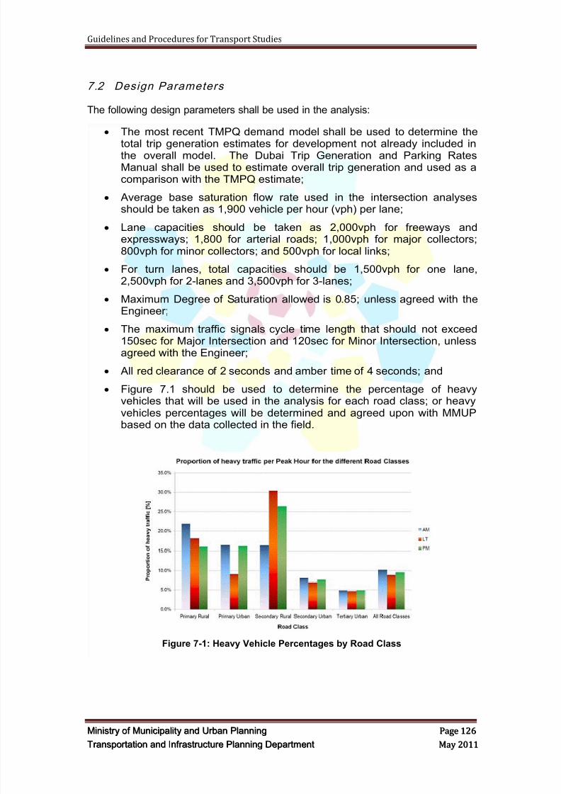
8/9/2019 TIPD Qatar Traffic Manual & Guidelines
http://slidepdf.com/reader/full/tipd-qatar-traffic-manual-guidelines 135/197
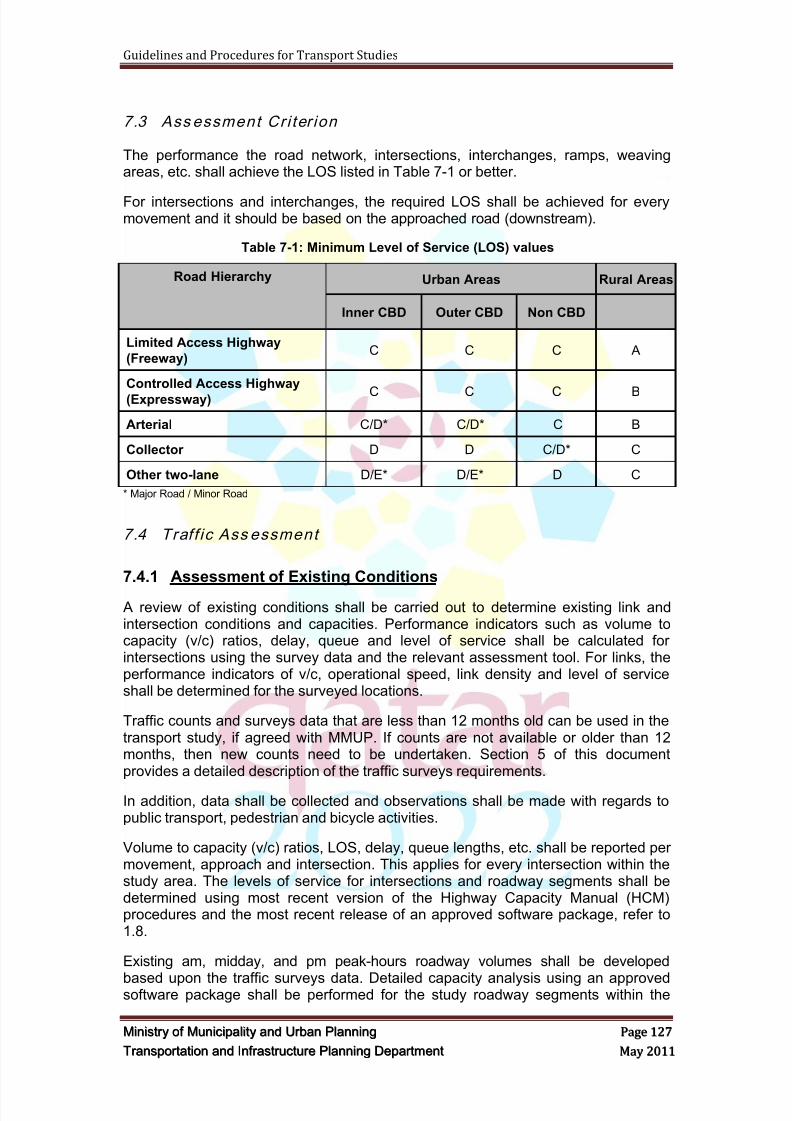
8/9/2019 TIPD Qatar Traffic Manual & Guidelines
http://slidepdf.com/reader/full/tipd-qatar-traffic-manual-guidelines 136/197
Guidelines and Procedures for Transport Studies
MMiinniissttr r yy oof f MMuunniicciippaalliittyy aanndd UUr r bbaann PPllaannnniinngg PPaaggee 112277
TTr r aannssppoor r ttaattiioonn aanndd IInnf f r r aassttr r uuccttuur r ee PPllaannnniinngg DDeeppaar r ttmmeenntt MMaayy 22001111
7.3 Ass essment Cri ter ion
The performance the road network, intersections, interchanges, ramps, weavingareas, etc. shall achieve the LOS listed in Table 7-1 or better.
For intersections and interchanges, the required LOS shall be achieved for everymovement and it should be based on the approached road (downstream).
Table 7-1: Minimum Level of Service (LOS) values
Road Hierarchy Urban Areas Rural Areas
Inner CBD Outer CBD Non CBD
Limited Access Highway
(Freeway)C C C A
Controlled Access Highway
(Expressway) C C C B
Arterial C/D* C/D* C B
Collector D D C/D* C
Other two-lane D/E* D/E* D C
* Major Road / Minor Road
7.4 Traff ic Ass essment
7.4.1 Assessment of Existing Conditions
A review of existing conditions shall be carried out to determine existing link andintersection conditions and capacities. Performance indicators such as volume tocapacity (v/c) ratios, delay, queue and level of service shall be calculated forintersections using the survey data and the relevant assessment tool. For links, theperformance indicators of v/c, operational speed, link density and level of serviceshall be determined for the surveyed locations.
Traffic counts and surveys data that are less than 12 months old can be used in thetransport study, if agreed with MMUP. If counts are not available or older than 12months, then new counts need to be undertaken. Section 5 of this documentprovides a detailed description of the traffic surveys requirements.
In addition, data shall be collected and observations shall be made with regards topublic transport, pedestrian and bicycle activities.
Volume to capacity (v/c) ratios, LOS, delay, queue lengths, etc. shall be reported permovement, approach and intersection. This applies for every intersection within thestudy area. The levels of service for intersections and roadway segments shall bedetermined using most recent version of the Highway Capacity Manual (HCM)procedures and the most recent release of an approved software package, refer to1.8.
Existing am, midday, and pm peak-hours roadway volumes shall be developed
based upon the traffic surveys data. Detailed capacity analysis using an approvedsoftware package shall be performed for the study roadway segments within the
8/9/2019 TIPD Qatar Traffic Manual & Guidelines
http://slidepdf.com/reader/full/tipd-qatar-traffic-manual-guidelines 137/197
8/9/2019 TIPD Qatar Traffic Manual & Guidelines
http://slidepdf.com/reader/full/tipd-qatar-traffic-manual-guidelines 138/197
Guidelines and Procedures for Transport Studies
MMiinniissttr r yy oof f MMuunniicciippaalliittyy aanndd UUr r bbaann PPllaannnniinngg PPaaggee 112299
TTr r aannssppoor r ttaattiioonn aanndd IInnf f r r aassttr r uuccttuur r ee PPllaannnniinngg DDeeppaar r ttmmeenntt MMaayy 22001111
performance indicators shall be analyzed and reported for each intersectionmovement and for the entire intersection.
A detailed capacity analysis using approved software shall be performed for thestudy roadway segments for all peak periods. If the arterial analysis is notappropriate, a generalized capacity analysis shall be performed for the study
roadway segments using an appropriate traffic/transport publication, e.g. the FloridaDepartment of Transportation (FDOT) Level of Service Handbook Tables. The TISshall comply with the adopted Level of Service standards of in Section 7.3 of thisdocument and Dubai Guidelines.
If roadway segments or intersections are operating below the adopted level ofservice in Section 7.3 of this document and in Dubai Guidelines, a recommendationfor mitigation shall be developed.
The Consultant shall identify roadway and/or intersection deficiencies resulting fromthe addition of project-generated traffic. The Consultant shall recommendimprovements necessary to restore the adopted level of service standards.
7.4.5 Initial Intersection and Link Assessment
An operational analysis for existing and projected future traffic for future design yearsshall be conducted to evaluate the traffic conditions on all critical links andintersections within each study area. This should be carried out by means of capacityand level of service analyses. For the purpose of this initial assessment, it isrecommended that the Consultant use SYNCHRO for signalized intersections andSIDRA for roundabouts (in accordance with the 2000 Highway Capacity Manual).
The output from the analysis shall include average delay per vehicle (d), level ofservice for each movement (LOS), average queue length (q), and degree ofsaturation (DOS) and v/c on each intersection movement.
For each peak period, both the base case and the mitigation options shall be testedbased on these analyses, the impact on the external road network shall bedetermined and the options refined. A minimum of LOS per Section 7.3 of thisdocument shall be achieved for each intersection movement and link per direction.
The analyses shall cover the following, where applicable:
Ramp intersection capacity analysis.
Ramp merge and diverge analysis.
Freeway weaving analysis.
Basic segments capacity and operational analysis.
Intersection capacity and operational analysis.
The following measures of performances for the three peak hour periods (morning,afternoon, and evening) shall be included in the output from the analysis for theexisting and future conditions:
Level of service for each movement and the overall intersection;
Average delay per vehicle;
95th
Percentile queue length per movement;
Link density per direction;
8/9/2019 TIPD Qatar Traffic Manual & Guidelines
http://slidepdf.com/reader/full/tipd-qatar-traffic-manual-guidelines 139/197

8/9/2019 TIPD Qatar Traffic Manual & Guidelines
http://slidepdf.com/reader/full/tipd-qatar-traffic-manual-guidelines 140/197
Guidelines and Procedures for Transport Studies
MMiinniissttr r yy oof f MMuunniicciippaalliittyy aanndd UUr r bbaann PPllaannnniinngg PPaaggee 113311
TTr r aannssppoor r ttaattiioonn aanndd IInnf f r r aassttr r uuccttuur r ee PPllaannnniinngg DDeeppaar r ttmmeenntt MMaayy 22001111
7.5 SIDRA As sessmen t
The Consultant shall prepare base year SIDRA models. These models shall beprepared for morning, mid-day and evening peak periods. Traffic design volumesderived from traffic surveys and the base year VISUM model shall be used.
The Consultant shall build models for the opening and future years. Traffic designvolumes derived from future VISUM model scenarios, as described in Section 6.18,shall be used.
The models shall be built for each mitigation option and shall be optimizedaccordingly. Mitigation options shall be prepared, discussed and submitted to MMUPfor approval prior and after the models analyses and assessments.
Design parameters included in Section 7.2 shall be used. The Consultant shall usethe default SIDRA parameters, e.g. lane capacity, gap acceptance, etc. However,parameters such as lane width and other geometric values can be modified
according to local conditions.
8/9/2019 TIPD Qatar Traffic Manual & Guidelines
http://slidepdf.com/reader/full/tipd-qatar-traffic-manual-guidelines 141/197
Guidelines and Procedures for Transport Studies
MMiinniissttr r yy oof f MMuunniicciippaalliittyy aanndd UUr r bbaann PPllaannnniinngg PPaaggee 113322
TTr r aannssppoor r ttaattiioonn aanndd IInnf f r r aassttr r uuccttuur r ee PPllaannnniinngg DDeeppaar r ttmmeenntt MMaayy 22001111
7.6 Synchro Ass essment
The Consultant shall prepare base year Synchro models. These models shall beprepared for morning, mid-day and evening peak periods. Traffic design volumesderived from traffic surveys and the base year VISUM model shall be used.
The Consultant shall build models for the opening and future years. Traffic designvolumes derived from future VISUM model scenarios, as described in Section 6.18,shall be used.
The models shall be built for each mitigation option and shall be optimizedaccordingly. Mitigation options shall be prepared, discussed and submitted to MMUPfor approval prior and after the models analyses and assessments.
Design parameters included in Section 7.2 shall be used. The Consultant shall usethe default synchro parameters, e.g. lane capacity, gap acceptance, etc. However,parameters such as lane width and other geometric values can be modified
according to local conditions.
8/9/2019 TIPD Qatar Traffic Manual & Guidelines
http://slidepdf.com/reader/full/tipd-qatar-traffic-manual-guidelines 142/197
Guidelines and Procedures for Transport Studies
MMiinniissttr r yy oof f MMuunniicciippaalliittyy aanndd UUr r bbaann PPllaannnniinngg PPaaggee 113333
TTr r aannssppoor r ttaattiioonn aanndd IInnf f r r aassttr r uuccttuur r ee PPllaannnniinngg DDeeppaar r ttmmeenntt MMaayy 22001111
7.7 VISSIM As sessmen t
The Consultant shall prepare base year VISSIM micro-simulation models for thestudy area. It is a standard practice to validate VISSIM base year models againstobserved travel times, saturation flows and turning flows. These models shall cover
the same morning, mid-day and evening peak periods that have been used in theVISUM model.
Once the base year VISSIM micro-simulation has been approved, the Consultantshall build models for the Preferred Option(s) for the opening and future years. TheConsultant shall use travel demand data output from the VISUM model for thispurpose. The Consultant shall advise and discuss with MMUP in regard to the type ofassignment to be used in the specific study, i.e. Static or Dynamic. Approval fromMMUP shall be obtained prior to any micro-simulation works.
Appropriate ‗warm up‘ and ‗cool down‘ periods shall be used. These periods shall bedetermined once the network is built and an initial analysis of the modeled areas is
carried out. These shall be added to the model to enable more accurate analysis ofthe peak hour conditions. The level of demand during these periods shall be basedon a ratio of the peak hour flow. This ratio is to be determined from survey data butis likely to be of the order of 80% of the full peak hour demand. The model shall berun 10 times with different random number seed values to ensure a spread of results.The average of these 10 runs shall be used to compare the relevant outputs againstthe VISUM model as outlined below.
The coverage of the VISSIM model shall include all of the preferred option designand in addition, the next adjacent major intersection on each boundary of thescheme. The Consultant shall modify in agreement with MMUP the VISSIMparameters relating to driver behavior, e.g. gap acceptance, lane changing, vehicle
composition, standstill distance and car following based on local conditions and thesurveys conducted for the project.
As mentioned earlier, the base models shall be validated by comparing modeledturning flows with observed turning flows.
The following outputs, taken as averages over each of the four 15 minutes periodswithin each peak hour, shall be used as the parameters for comparison:
Demand flows and actual numbers of vehicles entering and exiting thenetwork;
Vehicle volume, speed and density by roadway segment;
Average delay at each node; and
Output turning movements at each node.
In addition, the Consultant shall use the GEH test of goodness of fit, i.e. that themodel is deemed to be acceptable if 85% of compared values have a GEH value of5.0 or less.
The Consultant shall compare outputs from the VISSIM model to those results fromSYNCHRO and/or SIDRA analyses to illustrate general agreement between the twoapproaches.
The following sections provide MMUP‘s detailed guidelines for undertaking VISSIMmicro-simulation and documentation requirements.
8/9/2019 TIPD Qatar Traffic Manual & Guidelines
http://slidepdf.com/reader/full/tipd-qatar-traffic-manual-guidelines 143/197
Guidelines and Procedures for Transport Studies
MMiinniissttr r yy oof f MMuunniicciippaalliittyy aanndd UUr r bbaann PPllaannnniinngg PPaaggee 113344
TTr r aannssppoor r ttaattiioonn aanndd IInnf f r r aassttr r uuccttuur r ee PPllaannnniinngg DDeeppaar r ttmmeenntt MMaayy 22001111
7.7.1 Introduction
The major steps involved in creating a VISSIM micro-simulation model are:
a. Identification of Project Purpose, Scope, and Approach.b. Site visits that should be performed by the Consultant prior to setting the data
collection plan.c. Data Collection
This step involves the collection of input data for the micro-simulation modelas well selected output data for calibrating the model.
d. Coding
The model coding step is where the analyst converts the field data into inputsfor the micro-simulation model.
e. Error Checking
The error-checking step verifies the accuracy of the coded input data.
f. Calibration
Calibration is where the analyst adjusts the default parameters in thestandard behavioral models contained in the micro-simulation software tolocal conditions.
g. Validation
GEH and RMS calculations will validate the reliability of the model inreplicating existing conditions.
h. Alternatives Testing
This step is the purpose for which the micro-simulation model was developed.
i. Documentation
This step involves documenting the assumptions, analytical steps, and resultsof the analysis. It is important for ensuring that the decision makersunderstand the assumptions behind the results and for enabling otheranalysts to reproduce the results. Good documentation of a micro-simulationanalysis should include the following:
i. Project Objectives and Scope
ii. Overview of Project Approach (tools used, rationale)
iii. Data Collection (sources and methods)
iv. Calibration Tests and Results
v. Forecast Assumptions (assumed growth inside and outside of studyarea, street improvements, etc.)
vi. Description of Alternatives
vii. Results
Documentation is a vital step to preserve the rationale for the variousdecisions that are made in the process of developing, calibrating, andoperating a micro-simulation model. The documentation should be sufficientso that given the same input files, another analyst can understand thecalibration process, and repeat the alternatives analysis.
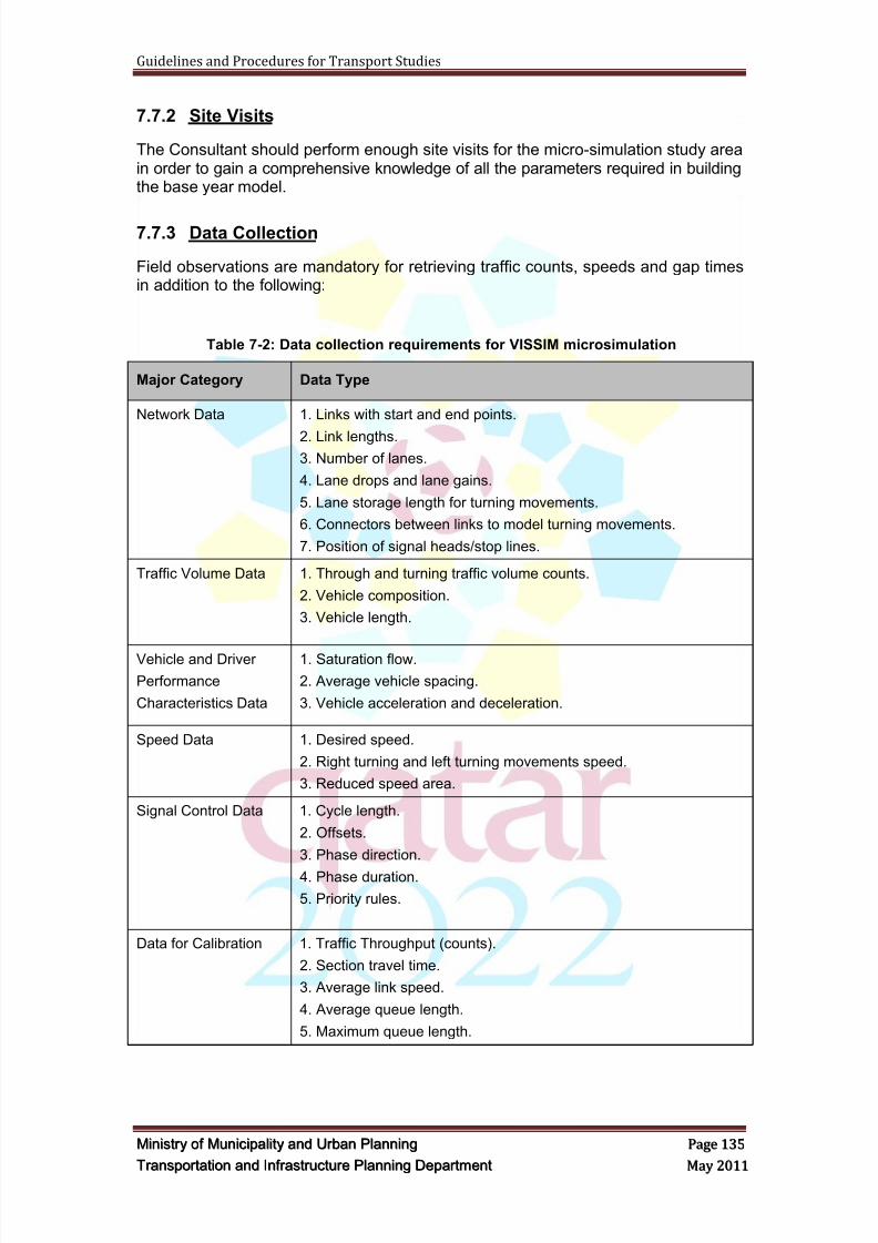
8/9/2019 TIPD Qatar Traffic Manual & Guidelines
http://slidepdf.com/reader/full/tipd-qatar-traffic-manual-guidelines 144/197
Guidelines and Procedures for Transport Studies
MMiinniissttr r yy oof f MMuunniicciippaalliittyy aanndd UUr r bbaann PPllaannnniinngg PPaaggee 113355
TTr r aannssppoor r ttaattiioonn aanndd IInnf f r r aassttr r uuccttuur r ee PPllaannnniinngg DDeeppaar r ttmmeenntt MMaayy 22001111
7.7.2 Site Visits
The Consultant should perform enough site visits for the micro-simulation study areain order to gain a comprehensive knowledge of all the parameters required in buildingthe base year model.
7.7.3 Data Collection
Field observations are mandatory for retrieving traffic counts, speeds and gap timesin addition to the following:
Table 7-2: Data collection requirements for VISSIM microsimulation
Major Category Data Type
Network Data 1. Links with start and end points.
2. Link lengths.3. Number of lanes.
4. Lane drops and lane gains.
5. Lane storage length for turning movements.
6. Connectors between links to model turning movements.
7. Position of signal heads/stop lines.
Traffic Volume Data 1. Through and turning traffic volume counts.
2. Vehicle composition.
3. Vehicle length.
Vehicle and Driver
Performance
Characteristics Data
1. Saturation flow.
2. Average vehicle spacing.
3. Vehicle acceleration and deceleration.
Speed Data 1. Desired speed.
2. Right turning and left turning movements speed.
3. Reduced speed area.
Signal Control Data 1. Cycle length.
2. Offsets.
3. Phase direction.
4. Phase duration.
5. Priority rules.
Data for Calibration 1. Traffic Throughput (counts).
2. Section travel time.
3. Average link speed.
4. Average queue length.
5. Maximum queue length.
8/9/2019 TIPD Qatar Traffic Manual & Guidelines
http://slidepdf.com/reader/full/tipd-qatar-traffic-manual-guidelines 145/197
Guidelines and Procedures for Transport Studies
MMiinniissttr r yy oof f MMuunniicciippaalliittyy aanndd UUr r bbaann PPllaannnniinngg PPaaggee 113366
TTr r aannssppoor r ttaattiioonn aanndd IInnf f r r aassttr r uuccttuur r ee PPllaannnniinngg DDeeppaar r ttmmeenntt MMaayy 22001111
7.7.4 Traffic Counts
ATC counts should be continuous for one week and should include volume, speed,and classification data. TMC counts timing should be based on the peak hour periodsrevealed from ATC counts and should be undertaken in the same day at least for themain intersections in the study area in order to achieve matching flows in the micro-simulation model.
During peak hours, Manual Classified Counts should include statistics about vehiclemodel distribution for passenger cars including standard short vehicle, standardmedium length vehicles, and four wheel drive vehicles.
7.7.5 Peak Hour Choice
Micro-simulation model peak hour periods should follow the peak hours of the majorintersections in the study area. Major intersections stands for the intersections withthe heaviest flows including a combination of background traffic and developmentrelated traffic in case of development project studies. Traffic volumes on the minoradjacent intersections should be extracted correspondingly with the chosen modelingpeak hour. Peak hour choice should be done in consultancy with MMUP.
7.7.6 Peak Hour Factor
Traffic counts analysis should provide the peak hour factor calculations in order toadjust the vehicle input volumes. Peak hour factors less than 0.9 require arechecking of the collected traffic data.
7.7.7 Public Transport Data Collection
In case of micro-simulating public transport systems, the Consultant has to collect theexisting and proposed routes, stops, and fleet data as well as the passenger demandand operational parameters such as headway, frequency, station capacity and dwelltimes. The Consultant has to liaise with MMUP prior to the implementation of thementioned data in the micro-simulation models.
7.7.8 Coding the Model
Coding the input data into the model is a major task. During this task the data onnetwork geometry, control, and demands is input into the micro-simulation model.
Three basic types of data are coded:
Network geometry (lanes, lengths, etc.)
Control data (signs, signal timing)
Demands
The steps involved in coding are:
a. Import and size overlay image (aerial photo or As-Built CAD file) for networkcoding. Importing an exported VISUM network is another option, but shouldbe checked and refined especially the intersections‘ layouts and connectors.
b. Code link attributes (lanes, free-flow speeds)
c. Code intersection attributes (control type, control parameters, turn lanedesignations, stop bars, turn pockets)
8/9/2019 TIPD Qatar Traffic Manual & Guidelines
http://slidepdf.com/reader/full/tipd-qatar-traffic-manual-guidelines 146/197
Guidelines and Procedures for Transport Studies
MMiinniissttr r yy oof f MMuunniicciippaalliittyy aanndd UUr r bbaann PPllaannnniinngg PPaaggee 113377
TTr r aannssppoor r ttaattiioonn aanndd IInnf f r r aassttr r uuccttuur r ee PPllaannnniinngg DDeeppaar r ttmmeenntt MMaayy 22001111
d. Code zones or nodes
e. Code vehicle types and origin-destination table(s).
f. The Consultant should code different colors for background and developmentrelated traffic. Even if the project is not operational in the existing conditions,its color coding will be used in the target year model.
g. Review/Revise default global parameters (vehicle characteristics, vehicle mix,etc.).
7.7.9 Error Checking
Before proceeding to calibration it is necessary to ensure that the model input datahas been entered correctly. Error checking involves various tests of the codednetwork. The steps involved in error checking are:
a. Color code links by attribute (lanes, facility type, free-flow speed, etc.) andidentify discrepancies.
b. Review intersection attributes.
c. Review demand inputs
d. Run model at very low volumes to identify errors.
e. Trace selected vehicles through the network.
f. Plot OD Desire Lines to visually verify demand entries.
7.7.10 Calibration
The objective of model calibration is to obtain the best match possible between
model performance estimates and the field measurements of performance. Theresponsibility lies with the modeler to implement a suitable procedure which providesan acceptable level of confidence in the model results. During VISSIM calibration,model outputs should be compared against field data to determine if the output iswithin acceptable levels.
The recommended calibration strategy is:
Check for and eliminate all obvious coding errors.
Calibrate the capacity related adjustment factors.
Calibrate the demand estimation parameters. Review of overall realism of model results (queues and travel times).
The calibration exercise must accomplish the following:
Task 1: Identification of peak periods recurring bottlenecks and queuing
Task 2: Modeled capacity to be within 10 percent of field measurements
Task 3: Model link versus observed flows and travel time to meet the followingcriteria:
Link volumes for more than 85 percent of cases to be:o Within 100 vph, for volumes less than 700 vpho Within 15 percent, for volumes between 700 vph and 2,700 vph
8/9/2019 TIPD Qatar Traffic Manual & Guidelines
http://slidepdf.com/reader/full/tipd-qatar-traffic-manual-guidelines 147/197
Guidelines and Procedures for Transport Studies
MMiinniissttr r yy oof f MMuunniicciippaalliittyy aanndd UUr r bbaann PPllaannnniinngg PPaaggee 113388
TTr r aannssppoor r ttaattiioonn aanndd IInnf f r r aassttr r uuccttuur r ee PPllaannnniinngg DDeeppaar r ttmmeenntt MMaayy 22001111
o Within 400 vph, for volumes greater than 2,700 vph
Link volumes for more than 85 percent of cases to have a GEH statistic lessthan five
Sum of link volumes to be within 5 percent
Sum of link volumes to have a GEH statistic less than four
Average travel time to be within 15 percent (or one minute, if higher) for theselected I-5 mainline segments
Task 4: Visually acceptable on- and off-ramp queuing
Task 5: Modeled average speeds to be within the acceptable range of observedspeeds on the mainline links. (Mainline links for data analysis were defined assections between consecutive on and off ramps)
Task 6: Visually acceptable utilization of the lanes at the lane drop locations and theHOV lane
Below are the different parameters that should be addressed during building and
calibrating the base year model.
a. Speed Parameters
i. Desired speed decision
S-shape curves should be deduced from ATC speed results and encodedin the desired speed distribution interface in VISSIM.
Desired speed locations should replicate actual speed signs locations.
ii. Reduced speed areas
Reduced speed areas should reflect the site measurements for the drivingspeed at curves, entrance and exit links, as well as road humps reducedspeed.
b. Gap Acceptance
i. Priority Rules (the default minimum gap acceptance of 3 sec should becalibrated with field measurement).
ii. Stop Signs for Special Impedance Modeling (a stop should be defined atimpeding location, and the actual delay should be measured in the fieldand encoded in a new dwell time distribution that should be defined andassigned to the installed stop.
c. Replicate Traffic Composition
Define Traffic Compositions (% of passenger cars, % of HGV, % of LGV, % ofBuses) for background traffic and development related traffic separately.Even if the project is not operational in the existing conditions, its trafficcomposition should be defined to be used in the target year model.
d. Replicate vehicle model distribution
Updating vehicle model distribution for passenger cars has a major role inimpacting the network capacity in general and the storage length capacityspecifically. For both background and development related passenger cartypes, the distribution of standard short vehicle, standard medium length
vehicles, and four wheel drive vehicles should be encoded in the vehiclemodel distribution interface in VISSIM.
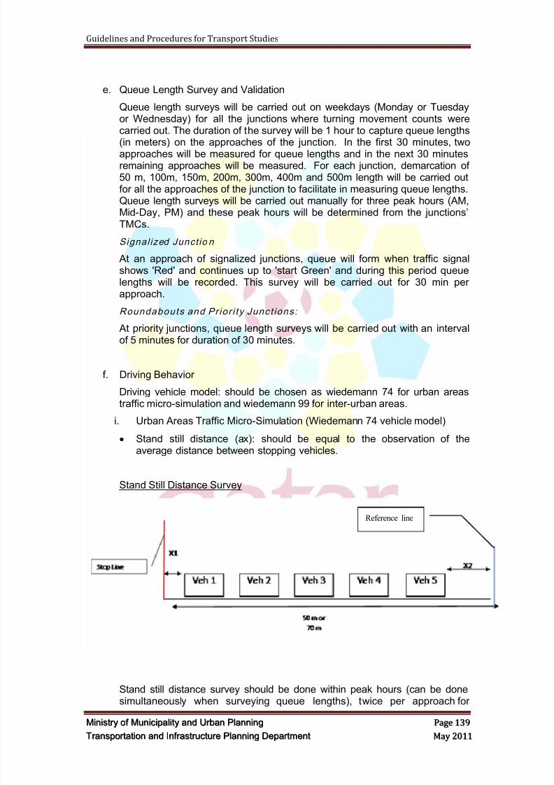
8/9/2019 TIPD Qatar Traffic Manual & Guidelines
http://slidepdf.com/reader/full/tipd-qatar-traffic-manual-guidelines 148/197
Guidelines and Procedures for Transport Studies
MMiinniissttr r yy oof f MMuunniicciippaalliittyy aanndd UUr r bbaann PPllaannnniinngg PPaaggee 113399
TTr r aannssppoor r ttaattiioonn aanndd IInnf f r r aassttr r uuccttuur r ee PPllaannnniinngg DDeeppaar r ttmmeenntt MMaayy 22001111
e. Queue Length Survey and Validation
Queue length surveys will be carried out on weekdays (Monday or Tuesdayor Wednesday) for all the junctions where turning movement counts werecarried out. The duration of the survey will be 1 hour to capture queue lengths(in meters) on the approaches of the junction. In the first 30 minutes, twoapproaches will be measured for queue lengths and in the next 30 minutesremaining approaches will be measured. For each junction, demarcation of50 m, 100m, 150m, 200m, 300m, 400m and 500m length will be carried outfor all the approaches of the junction to facilitate in measuring queue lengths.Queue length surveys will be carried out manually for three peak hours (AM,Mid-Day, PM) and these peak hours will be determined from the junctions‘TMCs.
Signal ized Junct io n
At an approach of signalized junctions, queue will form when traffic signal
shows 'Red' and continues up to 'start Green' and during this period queuelengths will be recorded. This survey will be carried out for 30 min perapproach.
Roundabouts and Prior i ty Junct ions:
At priority junctions, queue length surveys will be carried out with an intervalof 5 minutes for duration of 30 minutes.
f. Driving Behavior
Driving vehicle model: should be chosen as wiedemann 74 for urban areastraffic micro-simulation and wiedemann 99 for inter-urban areas.
i. Urban Areas Traffic Micro-Simulation (Wiedemann 74 vehicle model)
Stand still distance (ax): should be equal to the observation of theaverage distance between stopping vehicles.
Stand Still Distance Survey
Stand still distance survey should be done within peak hours (can be donesimultaneously when surveying queue lengths), twice per approach for
Reference line
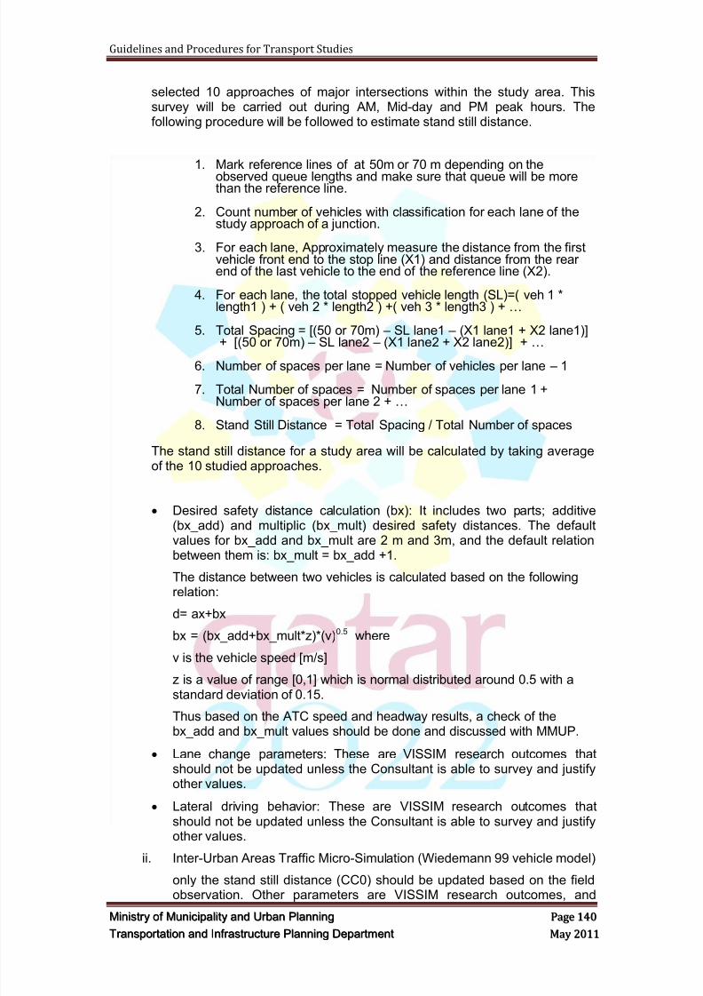
8/9/2019 TIPD Qatar Traffic Manual & Guidelines
http://slidepdf.com/reader/full/tipd-qatar-traffic-manual-guidelines 149/197
Guidelines and Procedures for Transport Studies
MMiinniissttr r yy oof f MMuunniicciippaalliittyy aanndd UUr r bbaann PPllaannnniinngg PPaaggee 114400
TTr r aannssppoor r ttaattiioonn aanndd IInnf f r r aassttr r uuccttuur r ee PPllaannnniinngg DDeeppaar r ttmmeenntt MMaayy 22001111
selected 10 approaches of major intersections within the study area. Thissurvey will be carried out during AM, Mid-day and PM peak hours. Thefollowing procedure will be followed to estimate stand still distance.
1. Mark reference lines of at 50m or 70 m depending on theobserved queue lengths and make sure that queue will be morethan the reference line.
2. Count number of vehicles with classification for each lane of thestudy approach of a junction.
3. For each lane, Approximately measure the distance from the firstvehicle front end to the stop line (X1) and distance from the rearend of the last vehicle to the end of the reference line (X2).
4. For each lane, the total stopped vehicle length (SL)=( veh 1 *length1 ) + ( veh 2 * length2 ) +( veh 3 * length3 ) + …
5. Total Spacing = [(50 or 70m) – SL lane1 – (X1 lane1 + X2 lane1)]
+ [(50 or 70m) – SL lane2 – (X1 lane2 + X2 lane2)] + … 6. Number of spaces per lane = Number of vehicles per lane – 1
7. Total Number of spaces = Number of spaces per lane 1 +Number of spaces per lane 2 + …
8. Stand Still Distance = Total Spacing / Total Number of spaces
The stand still distance for a study area will be calculated by taking averageof the 10 studied approaches.
Desired safety distance calculation (bx): It includes two parts; additive
(bx_add) and multiplic (bx_mult) desired safety distances. The defaultvalues for bx_add and bx_mult are 2 m and 3m, and the default relationbetween them is: bx_mult = bx_add +1.
The distance between two vehicles is calculated based on the followingrelation:
d= ax+bx
bx = (bx_add+bx_mult*z)*(v)0.5 where
v is the vehicle speed [m/s]
z is a value of range [0,1] which is normal distributed around 0.5 with a
standard deviation of 0.15.Thus based on the ATC speed and headway results, a check of thebx_add and bx_mult values should be done and discussed with MMUP.
Lane change parameters: These are VISSIM research outcomes thatshould not be updated unless the Consultant is able to survey and justifyother values.
Lateral driving behavior: These are VISSIM research outcomes thatshould not be updated unless the Consultant is able to survey and justifyother values.
ii. Inter-Urban Areas Traffic Micro-Simulation (Wiedemann 99 vehicle model)
only the stand still distance (CC0) should be updated based on the fieldobservation. Other parameters are VISSIM research outcomes, and
8/9/2019 TIPD Qatar Traffic Manual & Guidelines
http://slidepdf.com/reader/full/tipd-qatar-traffic-manual-guidelines 150/197
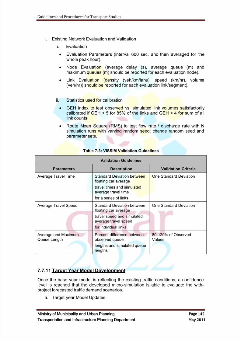
8/9/2019 TIPD Qatar Traffic Manual & Guidelines
http://slidepdf.com/reader/full/tipd-qatar-traffic-manual-guidelines 151/197
Guidelines and Procedures for Transport Studies
MMiinniissttr r yy oof f MMuunniicciippaalliittyy aanndd UUr r bbaann PPllaannnniinngg PPaaggee 114422
TTr r aannssppoor r ttaattiioonn aanndd IInnf f r r aassttr r uuccttuur r ee PPllaannnniinngg DDeeppaar r ttmmeenntt MMaayy 22001111
i. Existing Network Evaluation and Validation
i. Evaluation
Evaluation Parameters (interval 600 sec, and then averaged for the
whole peak hour).
Node Evaluation (average delay (s), average queue (m) andmaximum queues (m) should be reported for each evaluation node).
Link Evaluation (density (veh/km/lane), speed (km/hr), volume(veh/hr)) should be reported for each evaluation link/segment).
ii. Statistics used for calibration
GEH index to test observed vs. simulated link volumes satisfactorilycalibrated if GEH < 5 for 85% of the links and GEH < 4 for sum of all
link counts Route Mean Square (RMS) to test flow rate / discharge rate with N
simulation runs with varying random seed; change random seed andparameter sets.
Table 7-3: VISSIM Validation Guidelines
Validation Guidelines
Parameters Description Validation Criteria
Average Travel Time Standard Deviation between
floating car average
travel times and simulated
average travel time
for a series of links
One Standard Deviation
Average Travel Speed Standard Deviation between
floating car average
travel speed and simulated
average travel speed
for individual links
One Standard Deviation
Average and Maximum
Queue Length
Percent difference between
observed queue
lengths and simulated queue
lengths
80-120% of Observed
Values
7.7.11 Target Year Model Development
Once the base year model is reflecting the existing traffic conditions, a confidencelevel is reached that the developed micro-simulation is able to evaluate the with-project forecasted traffic demand scenarios.
a. Target year Model Updates
8/9/2019 TIPD Qatar Traffic Manual & Guidelines
http://slidepdf.com/reader/full/tipd-qatar-traffic-manual-guidelines 152/197
Guidelines and Procedures for Transport Studies
MMiinniissttr r yy oof f MMuunniicciippaalliittyy aanndd UUr r bbaann PPllaannnniinngg PPaaggee 114433
TTr r aannssppoor r ttaattiioonn aanndd IInnf f r r aassttr r uuccttuur r ee PPllaannnniinngg DDeeppaar r ttmmeenntt MMaayy 22001111
i. Geometry: should be updated based on the target year proposed layoutalternatives. Mitigations should be discussed with MMUP prior to testingthem.
ii. Speed and Reduced Speed Areas: should be updated correspondingly.
iii. Traffic Demand: strategic model sub-network demand matrices should beused in micro-simulating future traffic conditions.
iv. Traffic Control: should reflect the proposed traffic control plans fordifferent alternatives. Signal timing should be optimized in Synchro andthen coded into VISSIM. And mitigations should be discussed with MMUPprior to testing them.
b. Driving Behavior Parameters
Target year model will inherit the Driving Behavior Parameters defined in thebase year model, except when the strategic model reveals high share ofpublic transport (above 25%) in certain areas with proposed attractive publictransport facilities, then the default private transport VISSIM parameters shall
be used in consultancy with MMUP.
c. Assignment Procedures
i. Assignment procedure parameters except the routes‘ share split for staticroutes, should inherit the base year model parameters.
ii. In case of new routes being introduced in the target models, VISSIMdynamic assignment should be undertaken to forecast new routes‘ trafficload in the absence of justified static routes split.
iii. In case dynamic assignment is being performed in the calibration of thebase year VISSIM model, the same parameters will be used for the targetyear model based on the updated network and projected matrices.
d. Target year Micro-simulation evaluation
i. Evaluation Parameters (interval 600 sec, and then averaged for the wholepeak hour)
ii. Node Evaluation (average delay (s), average queue (m) and maximumqueues (m))
iii. Link Evaluation (speed (km/hr), volume (veh/hr), density (veh/km/lane))
7.7.12 Advance Micro-simulation
a. Advanced Micro-simulation including scripting or visual basic coding shouldbe discussed with MMUP prior to performing the evaluation run.
b. The capacity of gate system or any other proposed flow regulator systemshould be calibrated with field measurements of existing similar systems‘throughput or based on tested and justified new proposed technology.
7.7.13 Parking Micro-simulation
Parking dynamic assignment (using abstract parking lots) can be done for parkingareas with capacity less than 700 spaces; else, the simulation procedure should be
agreed on with MMUP.
8/9/2019 TIPD Qatar Traffic Manual & Guidelines
http://slidepdf.com/reader/full/tipd-qatar-traffic-manual-guidelines 153/197
Guidelines and Procedures for Transport Studies
MMiinniissttr r yy oof f MMuunniicciippaalliittyy aanndd UUr r bbaann PPllaannnniinngg PPaaggee 114444
TTr r aannssppoor r ttaattiioonn aanndd IInnf f r r aassttr r uuccttuur r ee PPllaannnniinngg DDeeppaar r ttmmeenntt MMaayy 22001111
7.7.14 Other Parameters
Parameters that are not covered by the above guidelines should be discussed withMMUP prior to assuming any value.
7.7.15 Otput
VISSIM is capable of producing output that contains measures of effectivenessincluding travel time, average link speed, total delay, stopped-time delay, stops,queue lengths, fuel emissions, fuel consumption, etc,. One advantage VISSIM has isthat it can produce very detailed results on any time interval defined by the user. Thisis a common need in research applications or when developing new controlalgorithms.
Both types of output, animation displays and numerical output in text files arereviewed to draw conclusions about traffic system performance. The animationdisplay shows the movement of individual vehicles through the network over thesimulation period. Text files report accumulated statistics on the performance of thenetwork. It is crucial that the Consultant review both numerical and animationoutputs, and not just one or the other, in order to gain a complete picture of theresults.
7.7.16 Volumes
Volumes may be reported as an accumulation (number of vehicles observed sincestart of time period), or a rate (number of vehicles observed since start of time perioddivided by the length of the time period, in hours)
7.7.17 Travel Time, Speed, and Delay
Travel time, speed, and delay are all travel time based measures of systemperformance. Delay isolates that portion of the travel time that is most objectionableto drivers. Mean system speed is a useful tool for normalizing the travel time resultsinto an index of overall system performance.
7.7.18 Stops
The number of stops is a useful indicator of the quality of signal progression. Thefewer stops there are, the better the progression.
7.7.19 Density
Density is used as a measure of the quality of service on freeways and highways.
Density may be reported as an instantaneous ―snapshot‖ value averaged over thelength of a link at different time points during the simulation. It is computed as thelength of the link multiplied by the number of lanes, divided by the number of vehiclespresent on the link when the snapshot is taken.
7.7.20 Queues
Queue lengths are important for identifying locations of heavy congestion in the
system. Queue overflows indicate locations needing more storage.
8/9/2019 TIPD Qatar Traffic Manual & Guidelines
http://slidepdf.com/reader/full/tipd-qatar-traffic-manual-guidelines 154/197
Guidelines and Procedures for Transport Studies
MMiinniissttr r yy oof f MMuunniicciippaalliittyy aanndd UUr r bbaann PPllaannnniinngg PPaaggee 114455
TTr r aannssppoor r ttaattiioonn aanndd IInnf f r r aassttr r uuccttuur r ee PPllaannnniinngg DDeeppaar r ttmmeenntt MMaayy 22001111
The mean queue, maximum queue, maximum back of queue, or 95 percentile queuemay be reported.
7.7.21 Summarization of Results
a. Selection of Key Summary StatisticsThe key is to focus on a few key indicators of system performance andlocalized breakdowns in the system.
b. Key Indicators of Overall System Performance
The key indicators of overall system performance are:
Vehicle-Miles Traveled (VMT) or Vehicle-Kilometers Traveled,
Vehicle-Hours Traveled (VHT), and
Mean System Speed.
Total system delay is another useful overall system performance measure,when it is available.
The number of stops is also useful for signal coordination studies.
c. Key Indicators of Localized Problems
The key indicators of localized problems are:
Link Queue Overflow Reports
Hot Spots Report
d. Summarizing the Key Statistics
The analyst needs to determine how the key statistics produced by multiple
simulation model run repetitions should be summarized.
e. Requirement for Multiple Repetitions
Micro-simulation models rely upon random numbers to generate vehicles,select their destination, select their route, and to determine their behavior asthey move through the network. No single simulation run can be expected toreflect any specific condition, such as the mean, the minimum, the maximum,or the 95 percentile. It is necessary to run the model several times withdifferent random number seeds i.e. 15, in order to get the necessary output todetermine mean, minimum, and maximum values. The analyst must thenpost-process the runs to obtain the necessary output statistics.
f. Summarizing the Results: Mean, Mode, MedianThe mean is the average value of a variable over the multiple repetitions ofthe simulation model runs with different random number seeds.
g. Mean and Standard Deviation
The most useful statistics for summarizing the results of many simulationmodel run repetitions are the mean and standard deviation of the results. Themean gives an indication of the center point of the results (and if the resultsare normally distributed, the mean also is the most frequently observedresult). The standard deviation gives an indication of how much the resultsvaried. The two statistics together can be used to determine confidence
intervals for the results and to test various hypotheses about the results.
8/9/2019 TIPD Qatar Traffic Manual & Guidelines
http://slidepdf.com/reader/full/tipd-qatar-traffic-manual-guidelines 155/197
Guidelines and Procedures for Transport Studies
MMiinniissttr r yy oof f MMuunniicciippaalliittyy aanndd UUr r bbaann PPllaannnniinngg PPaaggee 114466
TTr r aannssppoor r ttaattiioonn aanndd IInnf f r r aassttr r uuccttuur r ee PPllaannnniinngg DDeeppaar r ttmmeenntt MMaayy 22001111
7.7.22 VISSIM Documentation Guide
Variations from the VISSIM default parameters shall always be described and justified in the documentation.
Due to the extensive use of screen shots, the documentation should be in color.
a. Background Information
This section shall describe essential information about the model‘s purposeand scope, including the following:
A general description of the model
The location or corridor being modeled
The time of day being modeled (if time-specific, e.g., PM peak periodfrom 3:00-7:00 PM)
The purpose of the model
The original project limits The version of VISSIM used to develop the model (e.g., 5.1)
The model creation or completion date
b. Visual Representation of Model Elements
This section shall be a visual summary (in screen shot form) of keycomponents of the model as described in the preceding Sections includingthe following:
The background photo used to develop the model (usually Googlemap-based, or equivalent aerial view), with the model superimposedon the photo; include the scale of the original photo, if possible
Each key intersection (arterial) or interchange (freeway), in bothregular and centerline views, with pavement markings.
c. Inventory of Model Elements (by intersection or freeway segment)
This section shall provide a reference guide to the principal model components inthe form of a series of mostly graphical summary descriptions based on screenshots and some accompanying notes and comments. The model componentsdocumented are based on the principal menu and sub-menu options that areused to define, initialize, and control a VISSIM model. The model elements are asfollows (note that the model elements are listed in order of the tool baricons/modes and should be documented in this order):
1. Desired Speed Distributions
Describe the vehicle speed distributions used and how they were defined.
2. Vehicle Types
Describe in spreadsheet form the type, category, length, and class of vehicletypes (including pedestrian and bicycle categories).
3. Driver Behavior
List the driver behavior (CC) parameters used. Identify any parameters that
differ from the default value and justify why they differ.4. Link Types
8/9/2019 TIPD Qatar Traffic Manual & Guidelines
http://slidepdf.com/reader/full/tipd-qatar-traffic-manual-guidelines 156/197
Guidelines and Procedures for Transport Studies
MMiinniissttr r yy oof f MMuunniicciippaalliittyy aanndd UUr r bbaann PPllaannnniinngg PPaaggee 114477
TTr r aannssppoor r ttaattiioonn aanndd IInnf f r r aassttr r uuccttuur r ee PPllaannnniinngg DDeeppaar r ttmmeenntt MMaayy 22001111
Summarize each link type, including the associated vehicle class and driverbehavior set.
5. Traffic Compositions
Summarize each traffic composition used (including pedestrian and bicyclecategories). Provide the source and date of the traffic composition data usedto produce the model composition.
6. Signal Controllers
Describe each controller type and the associated files. Provide signal timingplans in a screen shot or by inclusion of the .vap file. Provide the source anddate of the signal timing data used to describe the model signal controllers.
7. Evaluation
Provide a description of any evaluation files or databases (include filenameand location).
8. Simulation Parameters
Describe parameters used to run the simulation, including simulation stepsize, seeding, etc.
9. Background Image
Provide the source photo used to develop the model geometry, and describethe photo‘s source and date. Include the scale of the photo, if possible.
10. Links/Connectors
Identify any data used to define unique geometry elements in the model,including lane closures, grade information, and lane change information.
11. Lane Assignments
Provide screen shots of all locations.
12. Traffic Volumes
Describe vehicle input locations and volume data. Include the source anddate of the information.
13. Routes and Relative Flow
Define each route and describe the source and date of relative flow data.
14. Desired Speed Decisions
Describe the locations of desired speed regions and define the associated
speed profiles and their rationale.15. Reduced Speed Areas
Describe the locations of reduced speed areas and define the associatedspeed profiles and their rationale.
16. Priority Rules for Non-Signalized Intersections
Describe the locations of non-signalized intersections. Also define the level ofdetail of the priority rules, as follows:
Basic: Minimum required right-of-way (ROW) rules were implementedfor vehicle traffic and pedestrian movements
Advanced: Additional conditions are modeled (e.g., such asoversaturated conditions)
8/9/2019 TIPD Qatar Traffic Manual & Guidelines
http://slidepdf.com/reader/full/tipd-qatar-traffic-manual-guidelines 157/197
Guidelines and Procedures for Transport Studies
MMiinniissttr r yy oof f MMuunniicciippaalliittyy aanndd UUr r bbaann PPllaannnniinngg PPaaggee 114488
TTr r aannssppoor r ttaattiioonn aanndd IInnf f r r aassttr r uuccttuur r ee PPllaannnniinngg DDeeppaar r ttmmeenntt MMaayy 22001111
Other: Other comments on the priority rules, including elements notmodeled, such as ―no pedestrian priority rules‖
Car/truck headways and gap time settings
17. Stop Signs for Non-Signalized Intersections
Describe locations
18. Roundabouts
Describe locations and clarify priority rules—particularly gap acceptance
19. Signal Heads
Describe locations.
20. Detectors
Describe locations, as well as the source and date of data used to definedetector locations.
21. Stop Signs for RTORDescribe locations.
22. Priority Rules for Signalized Intersections
Describe the locations of signalized intersections. Also define the level ofdetail of the priority rules, as follows:
Basic: Minimum required rules were implemented for vehicle trafficand pedestrian movements
Advanced: Additional conditions were modeled (e.g., such asoversaturated conditions)
Other: Other comments on the priority rules, including elements notmodeled such as ―no pedestrian priority rules‖
Car/truck headways and gap time settings
23. Transit (Stops)
Summarize transit stop locations and dimensions, passenger boarding data,and the source and date of the data upon which they are based.
24. Transit (Routes)
Summarize the transit routes, by intersection, the schedules and vehicletypes, and the source and date of the data upon which they are based.
25. Data Collection Points
Display data collection locations.
26. Travel Time Sections
Display travel time section locations.
27. Queue Counters
Display queue counter locations.
28. Parking Lots
Display parking lot locations.
29. Nodes
Display node locations.
8/9/2019 TIPD Qatar Traffic Manual & Guidelines
http://slidepdf.com/reader/full/tipd-qatar-traffic-manual-guidelines 158/197
Guidelines and Procedures for Transport Studies
MMiinniissttr r yy oof f MMuunniicciippaalliittyy aanndd UUr r bbaann PPllaannnniinngg PPaaggee 114499
TTr r aannssppoor r ttaattiioonn aanndd IInnf f r r aassttr r uuccttuur r ee PPllaannnniinngg DDeeppaar r ttmmeenntt MMaayy 22001111
30. Error File
Display error file (if significant) and corresponding simulation run date.
31. Output Files:
List the names of specific output files produced by the model, along with brief
descriptions. This information is noted if the model was originally developedto answer a specific analytical question, and the model produced output filesfor that specific analytical purpose. If so, those files should be identified hereso that, if necessary, answers to the analytical questions can be traced backto their supporting data. Because of the nature of output files that VISSIMproduces, it is often the case that additional post-processing (e.g., throughspreadsheets or statistical software) is required to either reformat the resultsinto a more usable form or to compute subsequent metrics. If that is the case,one can simply list the output files that formed the basis of the analyses andthen cite a separate document that discusses the analytical results derivedfrom those output files.
8/9/2019 TIPD Qatar Traffic Manual & Guidelines
http://slidepdf.com/reader/full/tipd-qatar-traffic-manual-guidelines 159/197
Guidelines and Procedures for Transport Studies
MMiinniissttr r yy oof f MMuunniicciippaalliittyy aanndd UUr r bbaann PPllaannnniinngg PPaaggee 115500
TTr r aannssppoor r ttaattiioonn aanndd IInnf f r r aassttr r uuccttuur r ee PPllaannnniinngg DDeeppaar r ttmmeenntt MMaayy 22001111
7.8 Weaving Analysis
The Consultant shall undertake weaving analysis for all roadway segments within thestudy area. The Consultant shall use and apply Highway Capacity Manual procedure
for weaving analysis. The Consultant shall submit all parameters that they intend touse in calculations to MMUP for approval.
7.9 Ramps Analysis
The Consultant shall undertake ramp analysis for all ramps within the study area.The Consultant shall use and apply Highway Capacity Manual procedure for rampanalysis. The Consultant shall submit all parameters that they intend to use incalculations to MMUP for approval.
7.10 Parking Analysis
7.11 Pedestrian Analysis
Level of service analysis is conducted for walkways and sidewalks, pedestrianqueuing areas, shared off-street paths, pedestrian crosswalks and pedestrianfacilities along streets.
For each pedestrian flow event a different level of service table has been developed.Care should be taken to apply the correct criteria, data and level of service tablewhen undertaking pedestrian analyses. Further information can be found in Appendix
F and the TMPQ reports titled Transport Planning Parameters for Qatar andPedestrian Design Guideline.
Importantly, world-wide trends in designing for pedestrians focus on establishingperformance criteria.
7.11.1 Pedestrian Assessment
Pedestrian studies should consider the following:
a. Safety and security of pedestrian links in and around the development;
b. Continuity, convenience and comfort of proposed pedestrian links;c. Exposure of pedestrians to the elements;
d. Distances pedestrians are required to walk in order to access thedevelopment or public transport nodes in the vicinity of the development;
e. Interaction of proposed pedestrian links with existing land uses and existingpedestrian desire lines;
f. Capacity of footpaths and pedestrian queuing and waiting areas (e.g. busstops, platforms, ticketing facilities) to cope with the additional pedestriandemands generated by the development;
g. Capacity of vertical transport components such as stairs, ramps, escalators
and lifts to cope with the additional pedestrian demands generated by thedevelopment;
8/9/2019 TIPD Qatar Traffic Manual & Guidelines
http://slidepdf.com/reader/full/tipd-qatar-traffic-manual-guidelines 160/197
Guidelines and Procedures for Transport Studies
MMiinniissttr r yy oof f MMuunniicciippaalliittyy aanndd UUr r bbaann PPllaannnniinngg PPaaggee 115511
TTr r aannssppoor r ttaattiioonn aanndd IInnf f r r aassttr r uuccttuur r ee PPllaannnniinngg DDeeppaar r ttmmeenntt MMaayy 22001111
h. Accessibility of pedestrian facilities for people with mobility impairments;
i. Number, type and nature of pedestrian-vehicle conflicts within and external tothe development; and
j. Pedestrian delays and risks at pedestrian-vehicle conflict points.
7.11.2 Pedestrian Crossing Delay
In busy activity centers where pedestrians and roadway users share the road spaceinevitable conflicts occur. In such cases a detailed study of the current and futurevehicle - pedestrian flow conditions are required. Increased traffic on the surroundingstreet system may result in increased delays to pedestrians attempting to cross roadsto access a development. Key data include:
Hourly counts of pedestrians at defined locations;
Hourly counts of vehicles;
Vehicle speeds at points where pedestrians are crossing the road; Observed delays to pedestrians crossing the street;
Pedestrian accident history;
Geometrical factors of the road.
Pedestrian studies reveal that there is a link between pedestrian delay and risktaking. These studies reveal that as pedestrian delay increases the likelihood of risktaking and non-compliance with traffic signals by pedestrian‘s increases.
7.12 Bicy cle Analys is
Procedures for undertaking bicycle analyses include consideration of the following:
Exclusive off-street bicycle paths
Shared off-street paths
Bicycle lanes on streets
Interrupted-flow bicycle facilities
Bicycle lanes on city streets
Similarly to pedestrians, LOS criteria have been developed for bicycle facilities.Care in the use of these tables is recommended. An example is shown in Table
7-4. Additional criteria are found in Appendix F.Table 7-4 Level of Service Criteria for Bicycle Lanes on City Streets
Level of Service Bicycle Travel Speed (km/hr)
A > 22
B > 15-22
C > 11-15
D > 8-11
E > 7-8
F < 7
Source: Transportation Research Board, Highway Capacity Manual.
8/9/2019 TIPD Qatar Traffic Manual & Guidelines
http://slidepdf.com/reader/full/tipd-qatar-traffic-manual-guidelines 161/197
Guidelines and Procedures for Transport Studies
MMiinniissttr r yy oof f MMuunniicciippaalliittyy aanndd UUr r bbaann PPllaannnniinngg PPaaggee 115522
TTr r aannssppoor r ttaattiioonn aanndd IInnf f r r aassttr r uuccttuur r ee PPllaannnniinngg DDeeppaar r ttmmeenntt MMaayy 22001111
Refer to the Transport Planning and Parameters Report for additional information.
7.12.1 Bicycle Assessment
Bicycle studies should consider the following:
Relationship of existing bicycle networks and facilities with those proposed inthe development or plan;
Capacity of bicycle paths and facilities to meet the bicycling demandsgenerated by a development or plan;
Bicycle links with public transport;
Safety of on-road facilities;
Smoothness, connectivity and directness of bicycle links;
Ability of bicyclist to maintain their speed on bicycle links;
Security and safety of off-road facilities; Number and nature of bicycle/vehicle and bicycle/pedestrian conflicts in a and
around the development or plan; and
Adequacy of end of trip end facilities (parking, change rooms and showers)
7.13 Publ ic Transp ort A nalysis
7.13.1 Public Transport Assessment
In reviewing the potential public transport implications of a major development, the
study should give consideration to:
Location and proximity of public transport nodes near development;
Capacity of public transport services to meet the demands generated by the newdevelopment; and
Impacts of service re-routing on route length and duration, timetablerescheduling, operational costs, maintenance costs and fleet sizes.
In any new development, opportunities to optimize the use of public transport mustbe pursued. MMUP will ask the question of whether public transport services arenecessary and, if so, whether they are available and adequate for that development.
With retail and commercial developments, direct pedestrian routes to bus stopsshould be considered. Wherever possible, the design should encourage the use ofpublic transport, and where significant public transport usage is likely, developmentbonuses such as a reduction in the requirement for on-site parking, may beconsidered.
Residential subdivisions should be located in proximity to existing developmentwhere possible, to assist in the design of bus routes. Subdivisions should ideallyhave at least two entrances to the major road network, to avoid circuitous busrouting. Subdivision design should also seek to meet public transport, cycling andwalking accessibility targets.
In the case of bus routes, development designs should seek to locate the maximum
number of dwellings within safe walking distance from an existing or potential busroute
8/9/2019 TIPD Qatar Traffic Manual & Guidelines
http://slidepdf.com/reader/full/tipd-qatar-traffic-manual-guidelines 162/197
Guidelines and Procedures for Transport Studies
MMiinniissttr r yy oof f MMuunniicciippaalliittyy aanndd UUr r bbaann PPllaannnniinngg PPaaggee 115533
TTr r aannssppoor r ttaattiioonn aanndd IInnf f r r aassttr r uuccttuur r ee PPllaannnniinngg DDeeppaar r ttmmeenntt MMaayy 22001111
The actual capacity of public transport services to meet demands generated bydevelopment will need to be identified in discussion with the public transportoperator. The hourly capacity of the services will be a function of the following:
Service frequencies - Many bus services are operated by private companies.The decision to increase service frequencies may represent a significant
investment risk to the operator and would only be considered if the operator cansee an reasonable and sustainable return on that investment;
Combined seated and standing passenger capacity of each vehicle. In someinstances state regulations or union agreements may limit the acceptablenumber of standing passengers; and
Existing levels of demand for services.
A bus route from an origin to a destination should be as close to a straight line aspossible (minimal deviations). Deviations assist in increasing the passenger exposureto the service; they are also likely to increase passenger travel times. Where deviationsto routes are under consideration, the following guidance should be followed to ensure
the negative impacts are limited: Total travel time whilst in the deviation should not exceed 10 minutes;
Deviation should not lengthen the route by more than 20 to 30 percent;
Average travel time per passenger on the route should not increase more than25 percent; and
Deviations should be located at the ends of the route rather than in the middle.
An extension to a route may result in an increase in the following operational costs:
Fuel costs
Vehicle wear and tear Driver wages
Maintenance.
An extension to an existing route may also require an operator to increase fleet sizeto meet peak period demands.
7.14 Mitigation Measur es
7.15 Recommendations and Options
The Consultant shall provide recommendations and options on the requiredmitigation measures to eliminate or minimize the traffic and/or safety impactgenerated by the proposed development/project on the affected road network,intersections, public transport facilities, and pedestrians and cyclists facilities.
The Consultant shall identify roadway segments and/or intersection deficienciesresulting from the additional generated traffic and address them in the TIS report.The Consultant shall recommend improvements necessary to restore the adoptedlevel of service standards as adopted in Section 7 of this document and Dubai
Guidelines. The Consultant shall inform their client, the Applicant, on their findingsand recommendations.
8/9/2019 TIPD Qatar Traffic Manual & Guidelines
http://slidepdf.com/reader/full/tipd-qatar-traffic-manual-guidelines 163/197
Guidelines and Procedures for Transport Studies
MMiinniissttr r yy oof f MMuunniicciippaalliittyy aanndd UUr r bbaann PPllaannnniinngg PPaaggee 115544
TTr r aannssppoor r ttaattiioonn aanndd IInnf f r r aassttr r uuccttuur r ee PPllaannnniinngg DDeeppaar r ttmmeenntt MMaayy 22001111
7.16 Impact As sessment Report
The Consultant shall prepare and submit Impact Assessment Report. The reportshall address all items included in this document and shall have the followingstructure as a minimum:
7.16.1 Description of Data
Data used to calibrate and validate the models shall be presented in summaryform e.g. traffic counts and travel time surveys, duration, time and day ofweek.
7.16.2 Base Year Models Description and Analyses
A description of the size of the study area, intersections, road segments,vehicle types modeled and percentage, time period, sensitivity tests andresults, details on calibration method and summary of calibration results shallbe provided.
7.16.3 Future Years Models Description and Analyses
A description of the future models and any changes from the Base Modelsshall be provided.
7.16.4 Summary of Base and Future Years Analyses
7.16.5 Conclusion of Base and Future years Analyses
7.16.6 Mitigation Measures and Options
7.16.7 Analyses of Mitigation Measures and Options
7.16.8 Conclusions and Recommendations
The Impact Assessment Report shall be prepared by a Senior Traffic Engineer.
The Impact Assessment Report shall be reviewed by either a Senior Traffic Engineeror the Manager of the Transportation Section/Department of the Traffic ConsultantFirm who has not been involved in preparing/writing the report.
7.17 Review Period
8/9/2019 TIPD Qatar Traffic Manual & Guidelines
http://slidepdf.com/reader/full/tipd-qatar-traffic-manual-guidelines 164/197
Guidelines and Procedures for Transport Studies
MMiinniissttr r yy oof f MMuunniicciippaalliittyy aanndd UUr r bbaann PPllaannnniinngg PPaaggee 115555
TTr r aannssppoor r ttaattiioonn aanndd IInnf f r r aassttr r uuccttuur r ee PPllaannnniinngg DDeeppaar r ttmmeenntt MMaayy 22001111
The estimated MMUP‘s technical review time is 10 working days, where extra timewould be required according to the project size.
In case the Model Report is returned as not approved, the Consultant shall submitthe revised report within three weeks.
7.18 Deliverables
The consultant shall submit the following:
The Impact Assessment Report, two hard copies.
The Impact Assessment Report, one digital copy.
The traffic analyses works, one digital copy.
8/9/2019 TIPD Qatar Traffic Manual & Guidelines
http://slidepdf.com/reader/full/tipd-qatar-traffic-manual-guidelines 165/197
Guidelines and Procedures for Transport Studies
MMiinniissttr r yy oof f MMuunniicciippaalliittyy aanndd UUr r bbaann PPllaannnniinngg PPaaggee 115566
TTr r aannssppoor r ttaattiioonn aanndd IInnf f r r aassttr r uuccttuur r ee PPllaannnniinngg DDeeppaar r ttmmeenntt MMaayy 22001111
8 REPORTING, MEETINGS AND PRESENTATION
The preceding analysis shall be summarized in a "Draft" report that will be submittedto MMUP for review and comments. One copy of the report will be submitted in draft
form. Upon receipt of the review comments, the Consultant shall produce a finalreport. Five copies of the final report will be prepared and submitted to MMUP.
The Consultant shall attend any meetings and prepare a PowerPoint presentation ifrequested by the MMUP regarding the TIS and Parking reports.
8.1 Format of the Traff ic Imp act Study
The TIS report shall include and follow the format outlined below as a minimum:
8.1.1 Study Introduction
The introduction of the transportation study shall include:
1. Detailed description of project;
2. Study procedures and methodology;
3. Site location map;
4. Site plan;
5. Location and description of access driveways; and
6. Date development will be fully occupied.
8.1.2 Defined Sub-Area Model
8.1.3 Defined Study Area
8.1.4 Existing Conditions
―Existing Traffic‖ conditions shall be provided:
1. Description of the existing land uses including the Dubai or ITE land useclassification and code.
2. Description of the existing roadway and intersection conditions including theirdesignation.
3. Traffic data, including:
a. Existing directional peak hour traffic volumes and level(s) of service on allcollector, arterial, expressway and freeways streets within the study area.
b. Existing turning movement volumes at the impacted intersection(s) andlevel(s) of service of those intersection(s).
Notes:
The above-required data shall be no older than 12 calendar months from the
submission of the TIS. Volumes shall be adjusted to reflect peak seasonconditions if adjustment factors are available.
8/9/2019 TIPD Qatar Traffic Manual & Guidelines
http://slidepdf.com/reader/full/tipd-qatar-traffic-manual-guidelines 166/197
Guidelines and Procedures for Transport Studies
MMiinniissttr r yy oof f MMuunniicciippaalliittyy aanndd UUr r bbaann PPllaannnniinngg PPaaggee 115577
TTr r aannssppoor r ttaattiioonn aanndd IInnf f r r aassttr r uuccttuur r ee PPllaannnniinngg DDeeppaar r ttmmeenntt MMaayy 22001111
The intersection capacity(s) shall be determined using the most recent updateof computer software based on the most recent edition of the HighwayCapacity Manual, (HCM, Transportation Research Board, Special Report 209).
8.1.5 Project Traffic Generation
8.1.6 Project Traffic Distribution
8.1.7 Projection of Future Background Traffic
8.1.8 Future with Project Traffic
8.1.9 Capacity Analysis
The level of service analysis for each roadway segment per direction and intersectionper movement shall be summarized in a table.
8.1.10 Traffic Circulation Issues
The study shall include a review of the traffic circulation plan, including ingress andegress from and to adjacent streets along with internal circulation, for automobiles,trucks and delivery vehicles, pedestrians, transit vehicles, and bicycles. The TISshall recommend mitigation strategies for solving any circulation issues.
8.1.11 Parking Analysis
8.1.12 Weaving Analysis
The Consultant shall submit all calculations and provide brief description andsummary of the weaving analysis.
The details of weaving analysis and the print out of the specialized software packageoutputs shall be provided in the appendices.
8.1.13 Road Safety Audit
The Consultant shall provide brief description and summary of road safety auditfindings and the Applicant/Consultant responses to the safety issues. The Applicantand/or his representative and the TIS Consultant shall ensure that all safety issuesraised by the Auditor have been reviewed and addressed.
The details of Road Safety Audit Report shall be provided in the appendices.
8.1.14 Conclusions
8.1.15 Recommendations
The TIS shall recommend methods of mitigation. The recommendations shall bepresented in ―bullet‖ format. The study shall identify transportation system
8/9/2019 TIPD Qatar Traffic Manual & Guidelines
http://slidepdf.com/reader/full/tipd-qatar-traffic-manual-guidelines 167/197
Guidelines and Procedures for Transport Studies
MMiinniissttr r yy oof f MMuunniicciippaalliittyy aanndd UUr r bbaann PPllaannnniinngg PPaaggee 115588
TTr r aannssppoor r ttaattiioonn aanndd IInnf f r r aassttr r uuccttuur r ee PPllaannnniinngg DDeeppaar r ttmmeenntt MMaayy 22001111
improvements necessary for the project to meet the level of standards as outlined inSection 7 of this document and Dubai Guidelines.
8.1.16 Appendices
The appendices of the study shall include:
1. Developments plans
2. Road networks and intersections plans
3. Detailed traffic data and surveys
4. Sketches showing distribution of trips for the project only and for the project withbackground traffic.
5. The output reports for the software used and pertinent calculation worksheets.
6. Road Safety Audit Report.
8.2 Review Period
The estimated MMUP‘s technical review time is 30 working days, where extra timewould be required according to the project size.
In case the Report is returned as not approved, the Consultant shall submit therevised report within three weeks.
8.3 Deliverables
The consultant shall submit the following:
The Draft Transport Study, two hard copies.
The Draft Transport Study, two digital copies.
The Final Transport Study, two hard copies.
The Final Transport Study, two digital copies.
8/9/2019 TIPD Qatar Traffic Manual & Guidelines
http://slidepdf.com/reader/full/tipd-qatar-traffic-manual-guidelines 168/197
Guidelines and Procedures for Transport Studies
MMiinniissttr r yy oof f MMuunniicciippaalliittyy aanndd UUr r bbaann PPllaannnniinngg PPaaggee 115599
TTr r aannssppoor r ttaattiioonn aanndd IInnf f r r aassttr r uuccttuur r ee PPllaannnniinngg DDeeppaar r ttmmeenntt MMaayy 22001111
APPENDIX A
CONCEPT DESIGN SUBMITTAL AND REVIEWGUIDELINES
8/9/2019 TIPD Qatar Traffic Manual & Guidelines
http://slidepdf.com/reader/full/tipd-qatar-traffic-manual-guidelines 169/197
Guidelines and Procedures for Transport Studies
MMiinniissttr r yy oof f MMuunniicciippaalliittyy aanndd UUr r bbaann PPllaannnniinngg PPaaggee 116600
TTr r aannssppoor r ttaattiioonn aanndd IInnf f r r aassttr r uuccttuur r ee PPllaannnniinngg DDeeppaar r ttmmeenntt MMaayy 22001111
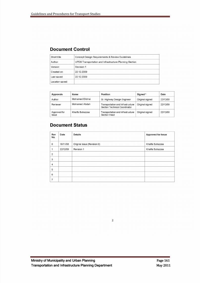
8/9/2019 TIPD Qatar Traffic Manual & Guidelines
http://slidepdf.com/reader/full/tipd-qatar-traffic-manual-guidelines 170/197
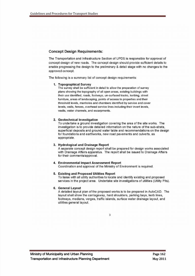
8/9/2019 TIPD Qatar Traffic Manual & Guidelines
http://slidepdf.com/reader/full/tipd-qatar-traffic-manual-guidelines 171/197
Guidelines and Procedures for Transport Studies
MMiinniissttr r yy oof f MMuunniicciippaalliittyy aanndd UUr r bbaann PPllaannnniinngg PPaaggee 116622
TTr r aannssppoor r ttaattiioonn aanndd IInnf f r r aassttr r uuccttuur r ee PPllaannnniinngg DDeeppaar r ttmmeenntt MMaayy 22001111
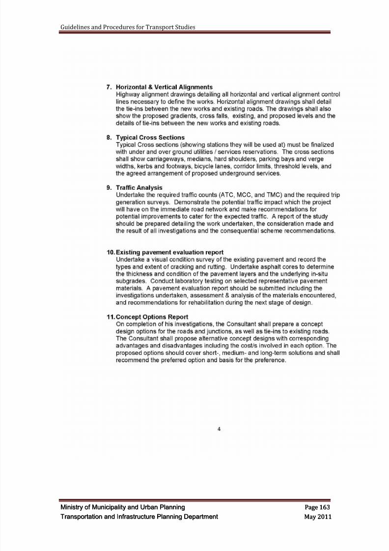
8/9/2019 TIPD Qatar Traffic Manual & Guidelines
http://slidepdf.com/reader/full/tipd-qatar-traffic-manual-guidelines 172/197

8/9/2019 TIPD Qatar Traffic Manual & Guidelines
http://slidepdf.com/reader/full/tipd-qatar-traffic-manual-guidelines 173/197
Guidelines and Procedures for Transport Studies
MMiinniissttr r yy oof f MMuunniicciippaalliittyy aanndd UUr r bbaann PPllaannnniinngg PPaaggee 116644
TTr r aannssppoor r ttaattiioonn aanndd IInnf f r r aassttr r uuccttuur r ee PPllaannnniinngg DDeeppaar r ttmmeenntt MMaayy 22001111
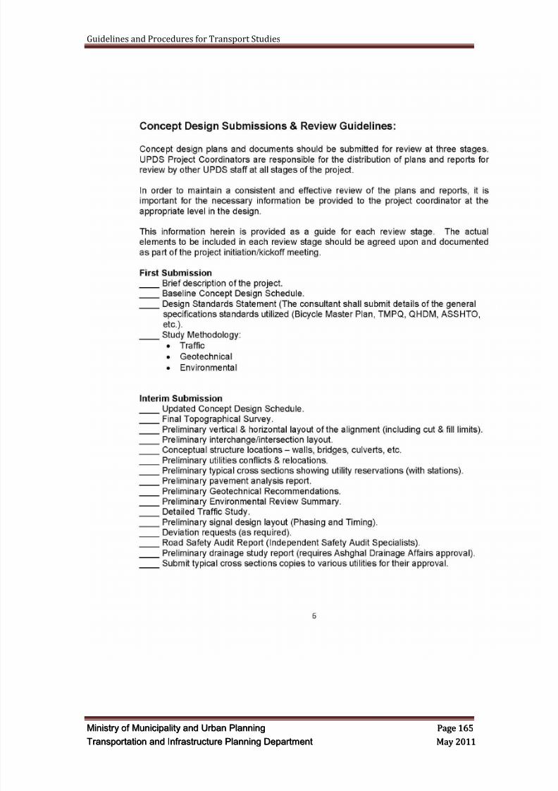
8/9/2019 TIPD Qatar Traffic Manual & Guidelines
http://slidepdf.com/reader/full/tipd-qatar-traffic-manual-guidelines 174/197
Guidelines and Procedures for Transport Studies
MMiinniissttr r yy oof f MMuunniicciippaalliittyy aanndd UUr r bbaann PPllaannnniinngg PPaaggee 116655
TTr r aannssppoor r ttaattiioonn aanndd IInnf f r r aassttr r uuccttuur r ee PPllaannnniinngg DDeeppaar r ttmmeenntt MMaayy 22001111
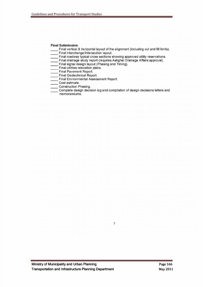
8/9/2019 TIPD Qatar Traffic Manual & Guidelines
http://slidepdf.com/reader/full/tipd-qatar-traffic-manual-guidelines 175/197
Guidelines and Procedures for Transport Studies
MMiinniissttr r yy oof f MMuunniicciippaalliittyy aanndd UUr r bbaann PPllaannnniinngg PPaaggee 116666
TTr r aannssppoor r ttaattiioonn aanndd IInnf f r r aassttr r uuccttuur r ee PPllaannnniinngg DDeeppaar r ttmmeenntt MMaayy 22001111
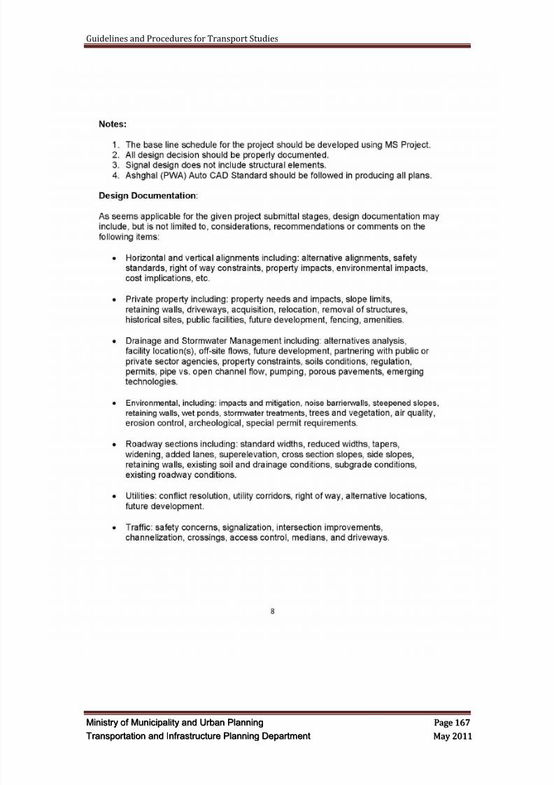
8/9/2019 TIPD Qatar Traffic Manual & Guidelines
http://slidepdf.com/reader/full/tipd-qatar-traffic-manual-guidelines 176/197
Guidelines and Procedures for Transport Studies
MMiinniissttr r yy oof f MMuunniicciippaalliittyy aanndd UUr r bbaann PPllaannnniinngg PPaaggee 116677
TTr r aannssppoor r ttaattiioonn aanndd IInnf f r r aassttr r uuccttuur r ee PPllaannnniinngg DDeeppaar r ttmmeenntt MMaayy 22001111
8/9/2019 TIPD Qatar Traffic Manual & Guidelines
http://slidepdf.com/reader/full/tipd-qatar-traffic-manual-guidelines 177/197
Guidelines and Procedures for Transport Studies
MMiinniissttr r yy oof f MMuunniicciippaalliittyy aanndd UUr r bbaann PPllaannnniinngg PPaaggee 116688
TTr r aannssppoor r ttaattiioonn aanndd IInnf f r r aassttr r uuccttuur r ee PPllaannnniinngg DDeeppaar r ttmmeenntt MMaayy 22001111
APPENDIX B
CONTEXT SENSITIVE DESIGN/SOLUTIONSCSD/CSS

8/9/2019 TIPD Qatar Traffic Manual & Guidelines
http://slidepdf.com/reader/full/tipd-qatar-traffic-manual-guidelines 178/197
Guidelines and Procedures for Transport Studies
MMiinniissttr r yy oof f MMuunniicciippaalliittyy aanndd UUr r bbaann PPllaannnniinngg PPaaggee 116699
TTr r aannssppoor r ttaattiioonn aanndd IInnf f r r aassttr r uuccttuur r ee PPllaannnniinngg DDeeppaar r ttmmeenntt MMaayy 22001111
Context Sensit ive Design/Solut ions CSD/CSS
1. INTRODUCTION
Application of Context Sensitive Design principles to the design of roadwaycorridors can significantly improve roads' amenity and safety. Roads designedfor functionality alone usually have poor amenity, split communities and can bedangerous to both motorists and pedestrians. In contrast roads that incorporateurban design principles are more pleasant places to be in, more livable,strengthen communities and are safer. Good connections enhance choice,support social cohesion, make places lively and safe, and facilitate contactamong people.
In simple terms, Context Sensitive Design (CSD) or Context Sensitive Solutions(CSS) is a concept that can be applied to plan or design a transportation facilitythat is sensitive to the community values and its context while maintaining itssafety and efficient mobility. This process is usually initiated at the early stagesof the project development and continues throughout the design stages in orderto produce plans for a transportation facility that is in harmony with its "context",a facility that enhances the sociability, economics and the environmental valuesof the community while maintaining its safety, mobility and accessibility.
What is the "co ntext"?
To better understand the context within which transportation project in located,we have to better understand the following elements:
a. Aesthetics,
b. Archeology,
c. Community Economics,d. Community culture,
e. Natural Environment,
f. Community historic values and elements,
g. Recreational facilities,
h. Scenic elements.
To put it in different terms, CSD/CSS involves understanding the transportationfacility and the land use at the micro and macro scales. At the micro scale, the"street" will be investigated in order to understand where and how it affects
specific places and elements within the community. At the micro scale, urban,suburban and rural contexts will be studied.
8/9/2019 TIPD Qatar Traffic Manual & Guidelines
http://slidepdf.com/reader/full/tipd-qatar-traffic-manual-guidelines 179/197
Guidelines and Procedures for Transport Studies
MMiinniissttr r yy oof f MMuunniicciippaalliittyy aanndd UUr r bbaann PPllaannnniinngg PPaaggee 117700
TTr r aannssppoor r ttaattiioonn aanndd IInnf f r r aassttr r uuccttuur r ee PPllaannnniinngg DDeeppaar r ttmmeenntt MMaayy 22001111
2. STREETS AS PLACES
Movement is not the sole function of the road. Streets are also places whichserve communities and powerfully represent the identity and visual quality of theareas public open space. To create memorable places that work on all theselevels and for all members of the community, a street should:
Help to build and strengthen the community it serves
Form part of a well connected network
Be attractive and have its own distinctive identity which reflects the uniquecontext of the area
Be cost effective to construct and maintain
Be safe for motorists and pedestrians
Provide efficient mobility and accessibility
The checklist below helps predict the quality of the street as a public space:
Context – the street’s position within the movement hierarchy willdetermine how intensively the space will be used
Activities bordering the space – surrounding land uses affected how muchactivity the street will attract.
Activities within the space – streets should be designed to accommodate
a range of activities Scale – scale needs to be appropriate to the intended function of the
street and adjoining land use density
Proportion – the degree of spatial containment will determine how well thestreet is defined spatially. The visual quality and overall sense of placewill be adversely affected if there is little containment
Geometrics - the geometric layout of the street will determine how it canaccommodate all necessary elements to fulfill its intended objectives
8/9/2019 TIPD Qatar Traffic Manual & Guidelines
http://slidepdf.com/reader/full/tipd-qatar-traffic-manual-guidelines 180/197
Guidelines and Procedures for Transport Studies
MMiinniissttr r yy oof f MMuunniicciippaalliittyy aanndd UUr r bbaann PPllaannnniinngg PPaaggee 117711
TTr r aannssppoor r ttaattiioonn aanndd IInnf f r r aassttr r uuccttuur r ee PPllaannnniinngg DDeeppaar r ttmmeenntt MMaayy 22001111
3. DETAILING THE PUBL IC REALM
The detail of the street has a significant impact on the quality of the space.i. Street furniture
Specification should ensure fitness of function, and minimize clutter.Many of the items in the street can be dispensed with. Quality should take precedence of quantity. Essential items can be grouped together.Signage and lighting can usually be tidied up by eliminating posts andcolumns and fixing to buildings.
ii. Street landscape
Generally, proper street landscape reduces wind speed, reduces pollutedair, improve appearance and create habitats. They can also add value to
housing bordering the street.
8/9/2019 TIPD Qatar Traffic Manual & Guidelines
http://slidepdf.com/reader/full/tipd-qatar-traffic-manual-guidelines 181/197
Guidelines and Procedures for Transport Studies
MMiinniissttr r yy oof f MMuunniicciippaalliittyy aanndd UUr r bbaann PPllaannnniinngg PPaaggee 117722
TTr r aannssppoor r ttaattiioonn aanndd IInnf f r r aassttr r uuccttuur r ee PPllaannnniinngg DDeeppaar r ttmmeenntt MMaayy 22001111
4. MULTI MODAL STREETS
Streets can be used to accommodate a wide range of uses. The range of usesbecame homogenized in the 20th century when priority was handed over to themovement and parking of vehicles. Good accessibility and circulation areessential in persuading people to take to walking, cycling and public transport.Space must be allocated for various modes, and for stops and stations. Spaceshould be provided within shared corridors to be efficient, provide choice,enhance visual amenity and create activity along the streets. Expanding roadwidths to accommodate increasing traffic volumes and alternative modes oftravel can result in extremely wide, inhospitable streets.
i. Street hierarchy
Hierarchy determines the type and extent of urban design treatment. The
following aspects therefore need to be considered: Traffic volume
Number of dwellings served
Type of vehicles accommodated
Whether or not there is direct access to properties
Scale
Enclosure
Carriageway and footpath widths
Street landscape
ii. Modifying driver behavior through design
Drivers often drive at what they perceive to be a safe speed, or what theyfeel is a reasonable speed even if this conflicts with signed speed limits.The design of the road layout, townscape and landscape can reduce thedisparity between the legal speed and the driver's perceived safe limit.Both horizontal (e.g. judder bars) and vertical (e.g. narrowing the road)traffic calming techniques can help modify driver behavior, as does givingall users of the street equal priority.
iii. Walkable neighborhoods
Street pattern and connectivity are critical to making a neighborhoodmore walkable. The following are important to consider when designingfor the pedestrian:
Pedestrian routes should be part of shared corridors and road space
Building frontages (doors and windows) should interact with thestreets, allowing enhanced informal surveillance
Street lighting for night time safety
Ensure routes are accessible for users of all abilities
Streets should be attractive places where people can interact sociallyand enjoy recreational activities such as walking and cycling.
8/9/2019 TIPD Qatar Traffic Manual & Guidelines
http://slidepdf.com/reader/full/tipd-qatar-traffic-manual-guidelines 182/197
Guidelines and Procedures for Transport Studies
MMiinniissttr r yy oof f MMuunniicciippaalliittyy aanndd UUr r bbaann PPllaannnniinngg PPaaggee 117733
TTr r aannssppoor r ttaattiioonn aanndd IInnf f r r aassttr r uuccttuur r ee PPllaannnniinngg DDeeppaar r ttmmeenntt MMaayy 22001111
iv. Accommodating the car
Promoting alternative modes of transport can reduce car use. Howvehicles are accommodated will have a significant impact on the qualityand usability of the public realm.

8/9/2019 TIPD Qatar Traffic Manual & Guidelines
http://slidepdf.com/reader/full/tipd-qatar-traffic-manual-guidelines 183/197
Guidelines and Procedures for Transport Studies
MMiinniissttr r yy oof f MMuunniicciippaalliittyy aanndd UUr r bbaann PPllaannnniinngg PPaaggee 117744
TTr r aannssppoor r ttaattiioonn aanndd IInnf f r r aassttr r uuccttuur r ee PPllaannnniinngg DDeeppaar r ttmmeenntt MMaayy 22001111
5. THE CSS PRODUCT: QUALITIES OF EXCELLENCE INTRANSPORTATION DESIGN
The following list of qualities (developed at a 1998 conference for transportation planners called "Think ing B eyond the Pavement" ) describe the core goals ofthe CSD/CSS process:
The project satisfies the purpose and needs as agreed to by a full range ofstakeholders.
This agreement is forged in the earliest phase of the project and amended aswarranted as the project develops.
The project is a safe facility for both the user and the community.
The project is in harmony with the community, and it preservesenvironmental, scenic, aesthetic, historic, and natural resource values of the
area. The project exceeds the expectations of both designers and stakeholders and
achieves a level of excellence in people's minds.
The project involves efficient and effective use of the resources (time, budget,community) of all involved parties.
The project is designed and built with minimal disruption to the community.
The project is seen as having added lasting value to the community.

8/9/2019 TIPD Qatar Traffic Manual & Guidelines
http://slidepdf.com/reader/full/tipd-qatar-traffic-manual-guidelines 184/197
Guidelines and Procedures for Transport Studies
MMiinniissttr r yy oof f MMuunniicciippaalliittyy aanndd UUr r bbaann PPllaannnniinngg PPaaggee 117755
TTr r aannssppoor r ttaattiioonn aanndd IInnf f r r aassttr r uuccttuur r ee PPllaannnniinngg DDeeppaar r ttmmeenntt MMaayy 22001111
6. URBAN DESIGN INVOLVEMENT IN DESIGN
DEVELOPMENT
The table below identifies when an urban design specialist would be involved inthe designing and engineering of a new road. Overall it is important to involvethe urban design specialist in all phases, with the nature of involvement varyingaccording to the needs of each phase.
Critically, urban design involvement is most needed in the first phase to establishkey frames of reference, evaluation criteria and specific requirements of MMUP.Later phases involve the creative application of these key considerations to thesite specific context of the project.
The table presented below illustrates the typical anticipated level and nature ofurban design input into the design of roadways.
TABLE OF URBAN DESIGN INVOLVEMENT PER TASK IN DESIGN PROCESS
PROJECT TASKS CONSULTANT MINISTRY OF MUNICIPALITY
AND URBAN PLANNING
Project Defini t ion and
Understanding Involvement of fullurban design team
Urban and Transportationdesign input essential to clarifyspecific requirements and keyexpectations.
Study Area Audi t Involvement of fullurban design team
Urban and Transportationdesign input essential to clarify
specific requirements providedata and confirm keyexpectations.
Photog raphic Record Urban designer Urban and Transportationdesign input essential to clarifyspecific requirements
Corr idor An alys is Involvement of fullurban design team
Urban and Transportationdesign input essential to clarifyspecific requirements, providedata and confirm key
expectations.
SWOT Analysis Involvement of fullurban design team
Urban and Transportationdesign input essential to clarifyspecific requirements, providedata and confirm keyexpectations.
Concept Design
Opt ions
Urban design inputrequired throughout the process to ensure keyurban design findings
and considerations areincorporated into each
Urban and Transportationdesign review of alternativeconcepts using agreed criteriaand key frames of reference
identified in Phases 1-4meeting. Recommendations
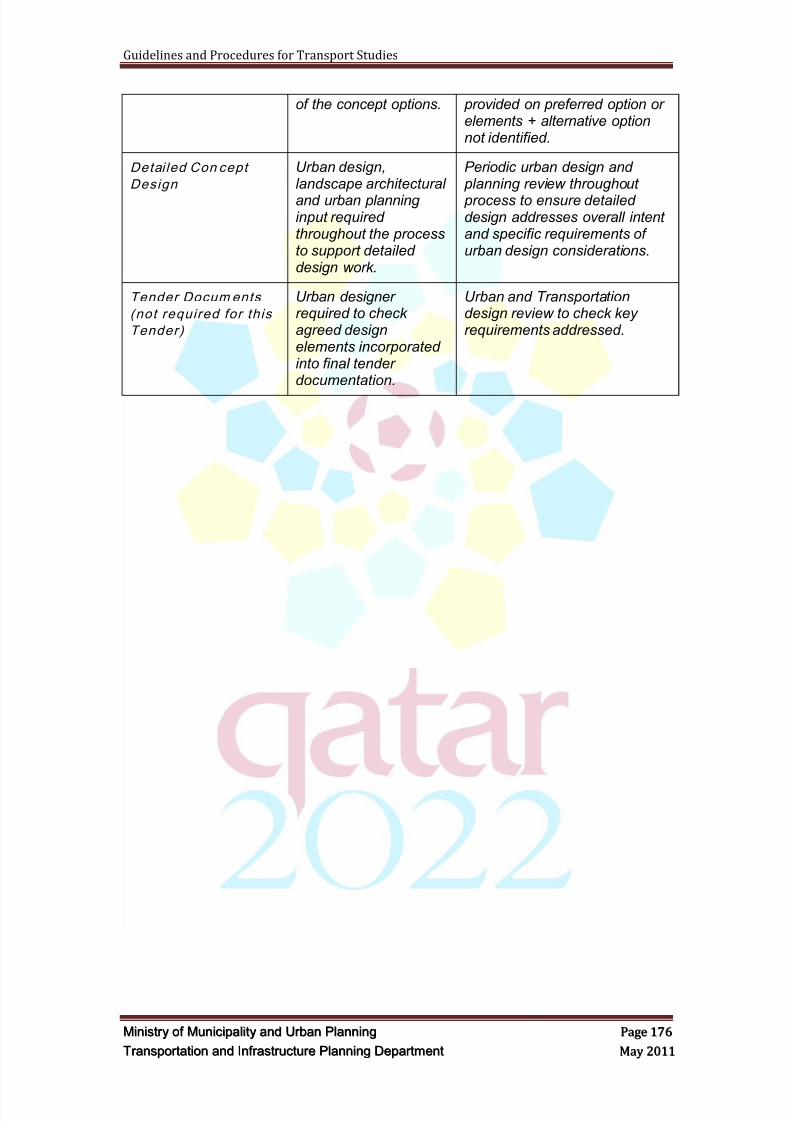
8/9/2019 TIPD Qatar Traffic Manual & Guidelines
http://slidepdf.com/reader/full/tipd-qatar-traffic-manual-guidelines 185/197
Guidelines and Procedures for Transport Studies
MMiinniissttr r yy oof f MMuunniicciippaalliittyy aanndd UUr r bbaann PPllaannnniinngg PPaaggee 117766
TTr r aannssppoor r ttaattiioonn aanndd IInnf f r r aassttr r uuccttuur r ee PPllaannnniinngg DDeeppaar r ttmmeenntt MMaayy 22001111
of the concept options. provided on preferred option orelements + alternative optionnot identified.
Detai led Con cept
Design Urban design,landscape architectural
and urban planninginput requiredthroughout the processto support detaileddesign work.
Periodic urban design and planning review throughout
process to ensure detaileddesign addresses overall intentand specific requirements ofurban design considerations.
Tender Docum ents
(not required for this
Tender)
Urban designerrequired to checkagreed designelements incorporatedinto final tenderdocumentation.
Urban and Transportationdesign review to check keyrequirements addressed.
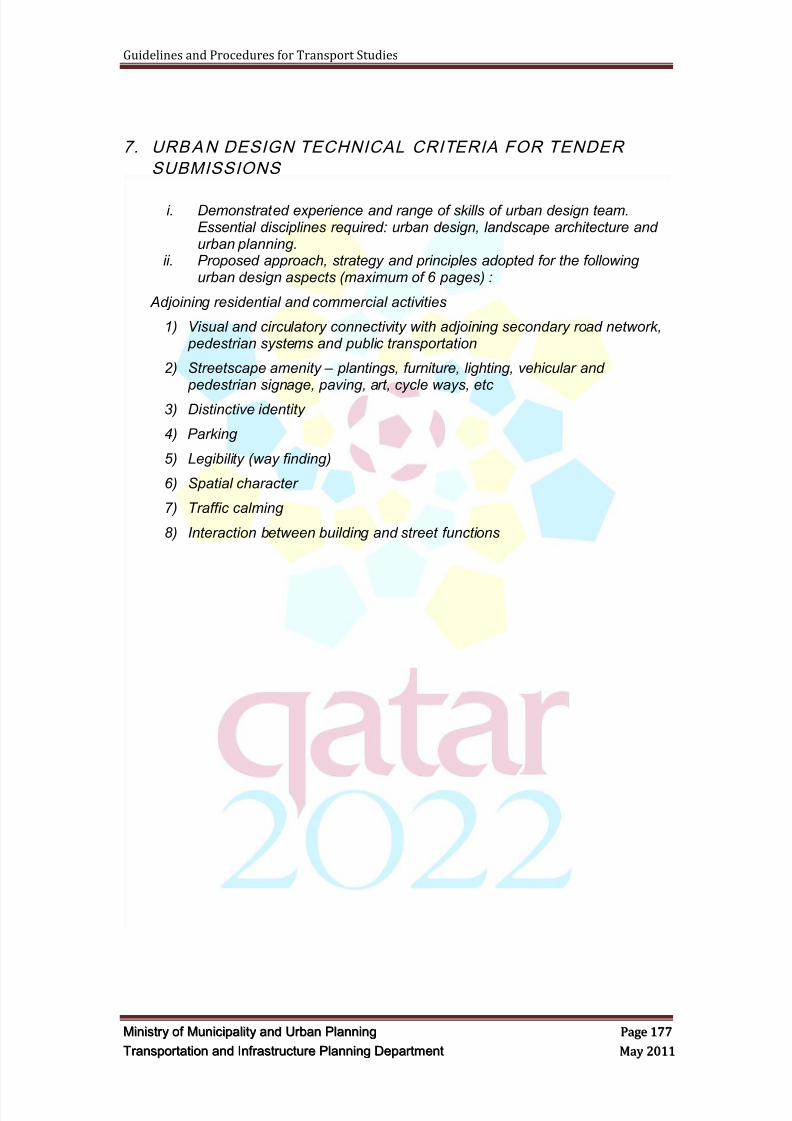
8/9/2019 TIPD Qatar Traffic Manual & Guidelines
http://slidepdf.com/reader/full/tipd-qatar-traffic-manual-guidelines 186/197
Guidelines and Procedures for Transport Studies
MMiinniissttr r yy oof f MMuunniicciippaalliittyy aanndd UUr r bbaann PPllaannnniinngg PPaaggee 117777
TTr r aannssppoor r ttaattiioonn aanndd IInnf f r r aassttr r uuccttuur r ee PPllaannnniinngg DDeeppaar r ttmmeenntt MMaayy 22001111
7. URBAN DESIGN TECHNICAL CRITERIA FOR TENDER
SUBMISSIONS
i. Demonstrated experience and range of skills of urban design team.Essential disciplines required: urban design, landscape architecture andurban planning.
ii. Proposed approach, strategy and principles adopted for the followingurban design aspects (maximum of 6 pages) :
Adjoining residential and commercial activities
1) Visual and circulatory connectivity with adjoining secondary road network, pedestrian systems and public transportation
2) Streetscape amenity – plantings, furniture, lighting, vehicular and pedestrian signage, paving, art, cycle ways, etc
3) Distinctive identity
4) Parking
5) Legibility (way finding)
6) Spatial character
7) Traffic calming
8) Interaction between building and street functions
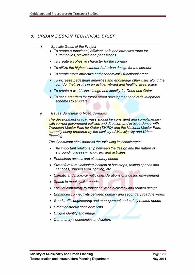
8/9/2019 TIPD Qatar Traffic Manual & Guidelines
http://slidepdf.com/reader/full/tipd-qatar-traffic-manual-guidelines 187/197
Guidelines and Procedures for Transport Studies
MMiinniissttr r yy oof f MMuunniicciippaalliittyy aanndd UUr r bbaann PPllaannnniinngg PPaaggee 117788
TTr r aannssppoor r ttaattiioonn aanndd IInnf f r r aassttr r uuccttuur r ee PPllaannnniinngg DDeeppaar r ttmmeenntt MMaayy 22001111
8. URBAN DESIGN TECHNICAL BRIEF
i. Specific Goals of the Project To create a functional, efficient, safe and attractive route for
automobiles, bicycles and pedestrians
To create a cohesive character for the corridor
To utilize the highest standard of urban design for the corridor
To create more attractive and economically functional areas
To increase pedestrian amenities and encourage other uses along thecorridor that results in an active, vibrant and healthy streetscape
To create a world class image and identity for Doha and Qatar
To set a standard for future street development and redevelopmentschemes to emulate.
ii. Issues Surrounding Road Corridors
The development of roadways should be consistent and complimentarywith current government policies and direction and in accordance withTransport Master Plan for Qatar (TMPQ) and the National Master Plan,currently being prepared by the Ministry of Municipality and UrbanPlanning.
The Consultant shall address the following key challenges:
The important relationship between the design and the nature ofsurrounding areas – land-uses and activities
Pedestrian access and circulatory needs
Street furniture: including location of bus stops, resting spaces andbenches, shaded area, lighting, etc.
Climatic and micro-climatic considerations of a desert environment
Space to meet cyclist needs
Lack of conformity to functional road hierarchy and related design
Enhanced connectivity between primary and secondary road networks
Good traffic engineering and management and safety related needs
Urban aesthetic considerations
Unique identity and image
Community’s economics and culture
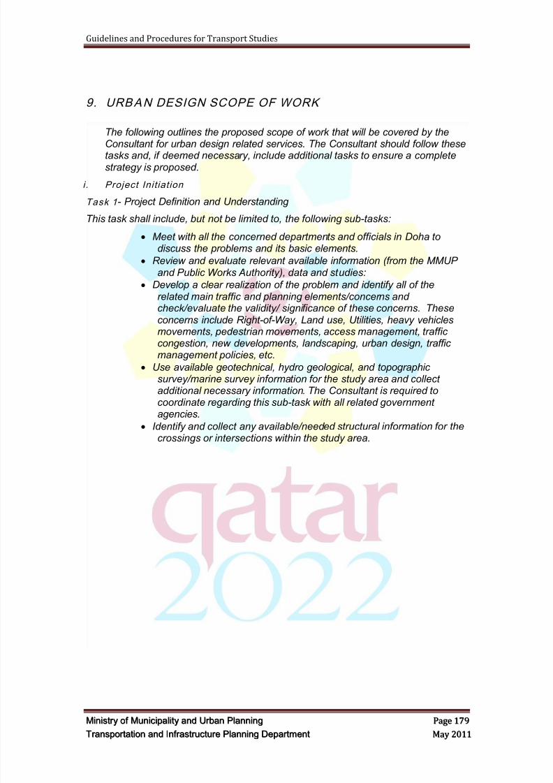
8/9/2019 TIPD Qatar Traffic Manual & Guidelines
http://slidepdf.com/reader/full/tipd-qatar-traffic-manual-guidelines 188/197
Guidelines and Procedures for Transport Studies
MMiinniissttr r yy oof f MMuunniicciippaalliittyy aanndd UUr r bbaann PPllaannnniinngg PPaaggee 117799
TTr r aannssppoor r ttaattiioonn aanndd IInnf f r r aassttr r uuccttuur r ee PPllaannnniinngg DDeeppaar r ttmmeenntt MMaayy 22001111
9. URBAN DESIGN SCOPE OF WORK
The following outlines the proposed scope of work that will be covered by theConsultant for urban design related services. The Consultant should follow thesetasks and, if deemed necessary, include additional tasks to ensure a completestrategy is proposed.
i . Project Init iation
Task 1 - Project Definition and Understanding
This task shall include, but not be limited to, the following sub-tasks:
Meet with all the concerned departments and officials in Doha todiscuss the problems and its basic elements.
Review and evaluate relevant available information (from the MMUP
and Public Works Authority), data and studies: Develop a clear realization of the problem and identify all of the
related main traffic and planning elements/concerns andcheck/evaluate the validity/ significance of these concerns. Theseconcerns include Right-of-Way, Land use, Utilities, heavy vehiclesmovements, pedestrian movements, access management, trafficcongestion, new developments, landscaping, urban design, trafficmanagement policies, etc.
Use available geotechnical, hydro geological, and topographicsurvey/marine survey information for the study area and collectadditional necessary information. The Consultant is required tocoordinate regarding this sub-task with all related government
agencies. Identify and collect any available/needed structural information for the
crossings or intersections within the study area.
8/9/2019 TIPD Qatar Traffic Manual & Guidelines
http://slidepdf.com/reader/full/tipd-qatar-traffic-manual-guidelines 189/197
Guidelines and Procedures for Transport Studies
MMiinniissttr r yy oof f MMuunniicciippaalliittyy aanndd UUr r bbaann PPllaannnniinngg PPaaggee 118800
TTr r aannssppoor r ttaattiioonn aanndd IInnf f r r aassttr r uuccttuur r ee PPllaannnniinngg DDeeppaar r ttmmeenntt MMaayy 22001111
Task 2 - Study Area Audit
The following will be completed as the Consultant defines the study area:
1) Identify the influence area of the project (corridors of the study) including
the surrounding land uses, intersections, and roundabouts, etc.2) Analyze the effect of any proposed and/ or committed relevant
improvement schemes (such as current zoning) and planned developmentwithin the area of influence, and particularly in relationship to accessibilityto adjacent land uses
3) Conduct necessary site visits and field reconnaissance to identify Right-of-Way limitations, land use properties, utilities and ground conditions.Detailed inventory should include, at a minimum, the following information:
Land Use
Current land use patterns and activities
Land values, land ownership
Detailed building and land uses at plot level (land and structures) Vacant undeveloped plots
Surrounding Land Uses
Dedicated land or property for public use, etc
Buildings
Buildings of architectural/cultural or historic value
Building heights (incompatibility, etc)
Conditions (excellent, good, acceptable, poor, dangerous, abandoned)
Buildings that are incompatible due to materials used or scale
Heritage and Cultural Uses
Pedestrian Circulation
Future Rights of Way and setback proposals or approvals if relevant
Curbs (conditions, handicapped accessible, etc)
Sidewalks and sikkas (conditions, width, etc)
Streetscape
Elements that promote visual quality, beautification and landscaping ina desert climate
Existing Amenities (Restaurants, Sitting Areas, etc.)
View corridors and sightlines that should be protected, enhanced orsecured
Appropriate Landscaping
Signage
Street furniture (lighting, garbage bins, benches, etc)
Cross walks
Development Applications
Permits issued but development not yet commenced
Review of Development Applications currently under processing andlikely to be approved
8/9/2019 TIPD Qatar Traffic Manual & Guidelines
http://slidepdf.com/reader/full/tipd-qatar-traffic-manual-guidelines 190/197
Guidelines and Procedures for Transport Studies
MMiinniissttr r yy oof f MMuunniicciippaalliittyy aanndd UUr r bbaann PPllaannnniinngg PPaaggee 118811
TTr r aannssppoor r ttaattiioonn aanndd IInnf f r r aassttr r uuccttuur r ee PPllaannnniinngg DDeeppaar r ttmmeenntt MMaayy 22001111
Major development projects under construction
Other Issues
Overhead wires
Pavement, Sightlines,
Visual distractions
Others
4) Study all available information related to the new developments within theStudy project area.
5) Clearly define the study area/corridors to be included in the study
Task 3 - Photographic Record
A photographic overview/summary of the existing roads must becompleted including a photographic record of each plot, building and landuse, tied digitally to the GIS database.
Task 1, 2 & 3 Deliverables
Technical Memorandum - Inventory of the Corridor (with Study AreaDefined) Report and Plan
Technical Memorandum - Inventory of the Plots Report and Plan
Digital Photographic Record tied to GIS system(digital)
All submittal shall be in English language The Consultant shall submit five (5) hardcopies of the reports, plans
(A0), etc.
The Consultant shall submit five (5) hardcopies of the digital formatsubmission
8/9/2019 TIPD Qatar Traffic Manual & Guidelines
http://slidepdf.com/reader/full/tipd-qatar-traffic-manual-guidelines 191/197
Guidelines and Procedures for Transport Studies
MMiinniissttr r yy oof f MMuunniicciippaalliittyy aanndd UUr r bbaann PPllaannnniinngg PPaaggee 118822
TTr r aannssppoor r ttaattiioonn aanndd IInnf f r r aassttr r uuccttuur r ee PPllaannnniinngg DDeeppaar r ttmmeenntt MMaayy 22001111
i i . Corridor Analysis
Task 4 - Analysis and Evaluation of Existing Conditions
This task should include but not necessarily be limited to:
Assemble all of the available data/information needed to analyze thecurrent traffic conditions on all major roads and interchanges /intersections within the study corridors. Any other data needed inthis regard to fully comprehend the solutions should be collected bythe Consultant. Recent counts at some of the key junctions withinthe Study Area Corridor are available from the MMUP.
Analyze the urban design implications of current traffic conditionswithin the study corridors.
Assess all relevant information relating to services along the corridorincluding electric, sewer, sanitary sewer, water, telecommunications,etc. In addition, any information relating to planned improvements of
servicing should also be obtained and included in the analysis. Identify and clearly diagnose the current issues/ causes of problems
within the Study Area.
Conduct a corridor and sub - area analysis.
Analyze the effect of any proposed and / or committed relevantimprovement schemes within the Study Area Corridor and review anyavailable previous studies done.
Study the urban design implications of any proposed geometricsolutions for surrounding links, interchanges and intersections andhighlight any relevant concerns / problems.
Analyze the effect of any proposed and / or committed relevantimprovement schemes on planned development within the area ofinfluence, and particularly in relationship to accessibility to adjacentland uses
Analyze and document the impact and relationship between existingland uses along the route in relation to roadways, access points, parking, sidewalks/streetscape, and other urban design elements
Identify key opportunities for concurrent mobility and infrastructureimprovements
Assess available Right-of-Way and identify any relevant issues andconcerns.
Assess current access conditions to surrounding communities anddevelopments and identify all issues/problems and suggest adequate
solutions for each. Document all the findings of this task in the form of a technical
memorandum.
Task 5 - Strengths, Weaknesses, Threats and Opportunities (SWOT) Analysis
The Consultant will prepare a SWOT Report and Map for submission tothe MMUP for review. The Report and Map will include a summary of thedata collected through the process and clearly indicate potentials forimproving the study areas.
8/9/2019 TIPD Qatar Traffic Manual & Guidelines
http://slidepdf.com/reader/full/tipd-qatar-traffic-manual-guidelines 192/197
Guidelines and Procedures for Transport Studies
MMiinniissttr r yy oof f MMuunniicciippaalliittyy aanndd UUr r bbaann PPllaannnniinngg PPaaggee 118833
TTr r aannssppoor r ttaattiioonn aanndd IInnf f r r aassttr r uuccttuur r ee PPllaannnniinngg DDeeppaar r ttmmeenntt MMaayy 22001111
Task 4 & 5 Deliverables
Strengths, Weaknesses, Opportunities and Constraints Report andPlan
All submittal shall be in English language
The Consultant shall submit five (5) hardcopies of the reports, plans
(A0), etc. The Consultant shall submit five (5) hardcopies of the digital format
submission
i i i . Concept Design Tasks
Task 6 - Concept Design Options
This task should include but may not necessarily be limited to:
Formulation of at least three preliminary concept plans that offer astrong and positive identity, an overall coordinated and vibrant
streetscape, enhance mobility, stimulate social/economic vitality andsupport the highest quality of urban aesthetics along the corridor.
Description of the character, design principles and approach used forthe plan – in both text and graphic format
Proposed land uses to enhance mobility, increase urban vitality andsupport urban aesthetics.
Sustainability approaches
Landscape concepts
Concepts on creative and innovative approaches to streetscapedesign for human comfort in a desert climate
Landscaping (Planting) concept
Concepts for the unifying and organizing elements that will give theroad corridor an exciting and unique identity
Concepts for special nodes or treatment areas
Conceptual Land Use Plan indicating parks/open spaces, urban plazas significant attractions such as restaurants/cafés, museums,galleries and/or outdoor theaters, other improvements and amenitiesand circulation patterns
Concepts for the location, size, configuration, function and treatmentof public open space (biking, walking, resting, sitting, etc.)
Hard and soft landscape concepts (turf areas, planting beds,shade/feature trees, walkways, play areas, site furniture, retainingwalls, fencing, etc.), ambient/decorative lighting
Concepts for the treatment of areas for special features and public art(sculptures, fountains, wall murals, etc.)
Proposed road cross sections
Bicycle Linkages
An evaluation of each alternative concept plan using a process andsupporting assessment criteria agreed to with MM & UP. This mayinvolve recommending the selection of one alternative concept planor elements of each alternative concept plan developed into a newalternative concept.
8/9/2019 TIPD Qatar Traffic Manual & Guidelines
http://slidepdf.com/reader/full/tipd-qatar-traffic-manual-guidelines 193/197
8/9/2019 TIPD Qatar Traffic Manual & Guidelines
http://slidepdf.com/reader/full/tipd-qatar-traffic-manual-guidelines 194/197
Guidelines and Procedures for Transport Studies
MMiinniissttr r yy oof f MMuunniicciippaalliittyy aanndd UUr r bbaann PPllaannnniinngg PPaaggee 118855
TTr r aannssppoor r ttaattiioonn aanndd IInnf f r r aassttr r uuccttuur r ee PPllaannnniinngg DDeeppaar r ttmmeenntt MMaayy 22001111
Proposed Preliminary and Detailed Conceptual Plans at appropriatescales to show the overall schemes and significant sub-areas ingreater detail to the approval of MMUP
Clear and neat presentation boards showing the necessaryinformation of the proposed schemes – As required and agreed
A 3D video presentation All submittal shall be in English language
The Consultant shall submit five (5) hardcopies of the reports, plans(A0) of all Maps and Graphics, etc.
The Consultant shall submit five (5) hardcopies of the digital formatsubmission
8/9/2019 TIPD Qatar Traffic Manual & Guidelines
http://slidepdf.com/reader/full/tipd-qatar-traffic-manual-guidelines 195/197
Guidelines and Procedures for Transport Studies
MMiinniissttr r yy oof f MMuunniicciippaalliittyy aanndd UUr r bbaann PPllaannnniinngg PPaaggee 118866
TTr r aannssppoor r ttaattiioonn aanndd IInnf f r r aassttr r uuccttuur r ee PPllaannnniinngg DDeeppaar r ttmmeenntt MMaayy 22001111
APPENDIX C
PARKING DESIGN GUIDELINES
8/9/2019 TIPD Qatar Traffic Manual & Guidelines
http://slidepdf.com/reader/full/tipd-qatar-traffic-manual-guidelines 196/197
APPENDIX D
PEDESTRIAN FACILITIES DESIGN GUIDELINES

8/9/2019 TIPD Qatar Traffic Manual & Guidelines
http://slidepdf.com/reader/full/tipd-qatar-traffic-manual-guidelines 197/197