tm 5-4310-270-15 - free military army manuals! · tm 5-4310-270-15 department ofthe army technical...
TRANSCRIPT

TM 5-4310-270-15D E P A R T M E N T O F T H E A R M Y T E C H N I C A L M A N U A L
O P E R A T O R A N D O R G A N I Z A T I O N A L
D I R E C T A N D G E N E R A L S U P P O R T A N D D E P O T
M A I N T E N A N C E M A N U A L
C O M P R E S S O R , R O T A R Y , P O W E R D R I V E N , A I R ,
T W O I M P E L L E R , W H E E L B A R R O W
F R A M E M O U N T E D , T W O P N E U M A T I C T I R E S ,
G A S O L I N E E N G I N E 6 0 C F M , 6 . 5 P . S . I .
( F U L L E R M O D E L 2 M S W B )
F S N 4 3 1 0 - 9 0 6 - 8 9 9 4
H E A D Q U A R T E R S , D E P A R T M E N T O F T H E A R M Y
S E P T E M B E R 1 9 6 7
SAFETY PRECAUTIONS
BEFORE OPERATIONWhen handling gasoline, always provide a metal-to-metal contact between the container and
tank. This will prevent a spark from being generated as gasoline flows over the metallic surface.Never attempt to service any of the air compressor components until the unit is relieved of
all air pressure.Do not operate the air compressor in an inclosed area unless the exhaust gases are piped
to the outside. The exhaust gases contain carbon monoxide, which is a colorless, odorless, andpoisonous gas.
DURING OPERATIONNever attempt to service any of the air compressor components until the unit is relieved of
all pressure.
AFTER OPERATIONWhen handling gasoline, always provide a metal-to-metal contact between the container and
tank. This will prevent a spark from being generated as gasoline flows over the metallic sur-faces.
Never attempt to service any of the air compressor components until the unit is relieved ofall air pressure.
Be extremely careful when using a carbon tetrachloride fire extinguisher in an enclosed area.A poisonous gas is generated by the contact of carbon tetrachloride with a heated metallicsurface. Provide adequate ventilation before entering an inclosed area where carbon tetra-chloride has been used.

Changes in force: C 1 and C 2
Change
No. 2
TM 5-4310-270-15C 2
HEADQUARTERSDEPARTMENT OF THE ARMYWASHINGTON , DC 28 August 1974
Operator, Organizational, Direct and General Support,and Depot Maintenance Manual
COMPRESSOR, ROTARY, AIR; POWER DRIVEN; TWO IMPELLER; WHEEL-BARROW FRAME MOUNTED; TWO PNEUMATIC TIRES; GASOLINE ENGINE;
60 CFM, 6.5 PSI (FULLER MODEL 2MSWB) FSN 4310-906-8994
TM 54310-270-15, 11 September 1967, is changed asfollows:Reverse of cover page. Add to Safety Precautions:
WARNINGThis compressor is NOT SUITABLE for thesupply of air for charging cylinders withBREATHABLE AIR.
WARNINGOperation of this equipment presents aNOISE HAZARD to presonnel in the area.The noise level exceeds the allowable limitsfor unprotected personnel. Wear ear plugs orear muffs which were fitted by a trainedprofessional.
WARNINGCleaning solvent, PD-680, is POTEN-TIALLY DANGEROUS chemical. Do notuse near open flame.
Page 2-3. Paragraph 2-5e is added.
with TB MED-251. The signs should read:
WARNINGNOISE HAZARD EQUIPMENT. HEAR-ING PROTECTION REQUIRED.
Page 2-7. Paragraph 2-13, add:WARNING
Operation of this equipment presents aNOISE HAZARD to personnel in the area.Wear ear muffs or ear plugs which werefitted by a trained professional.
WARNINGThis compressor is NOT SUITABLE for thesupply of air for charging cylinders withBREATHABLE AIR.
Page 3-1. Paragraph 3-4b, add:WARNING
Cleaning solvent, PD-680, used for cleaninge. Noise Hazard Warning Signs. Signs conforming is POTENTIALLY DANGEROUS CHEM-
to provisions of AR 385-30 will be erected in the area to ICAL. Do not use near open flame. Flashprovide notification of NOISE HAZARD in accordance point of solvent is 100- 138F°. (38-59° C. ).
1

By Order of the Secretary of the Army:
Official:VERNE L. BOWERSMajor General, United States ArmyThe Adjutant General
CREIGHTON W. ABRAMSGeneral, United States ArmyChief of Staff
Distribution:To be distributed in accordance with DA Form 12-25A (qty rqr block No. 30) Organizational Maintenance
requirements for Air Compressors, 60 CFM.
2
PIN : 6 7 0 9 1 1 - 0 0 2


Table 2-1.


TM 5-4310-270-15
T ECHNICAL M A N U A L
No. 5-4310-270-15
CHAPTER 1.Section I.
II.
CHAPTER 2.Section I.
II.III.IV.
CHAPTER 3.Section I.
II.III.IV.V.
VI.VII.
VIII.IX.X.
XI.XII.
CHAPTER 4.Section I.
II.
CHAPTER 5.Section I.
II.III.IV.
HEADQUARTERSDEPARTMENT OF THE ARMY
Washington, D. C., 11 September 1967
Operator And OrganizationalDirect And General Support And Depot
Maintenance Manual
COMPRESSOR ROTARY, POWER DRIVEN, AIR,TWO IMPELLER, WHEELBARROW
FRAME MOUNTED, TWO PNEUMATIC TIRES, GASOLINEENGINE 60 CFM, 6.5 P.S.I.(FULLER MODEL 2MSWB)
FSN 4310-906-8994
Paragraph Page
Introduction . . . . . . . . . . . . . . . . . . . . . . . . . . . . . . . . . . . . . . . . . . . . . . . .. . . . . . . . . . . . . . . . . . . . . . . . . 1-1General . . . . . . . . . . . . . . . . . . . . . . . . . . . . . . . . . . . . . . . . . .. . . . . . . . . . . . . . . . . . . . . . . . . . 1-1 1-1Description and tabulated data . . . . . . . . . . . . . . . . . . . . . . . . . . . . . . . . . . . . . . . . . . . . . . . 1-3 1-1
Installation and Operating Instructions . . . . . . . . . . . . . . . . . . . . . . . . . . . . . . . . . . . . . . . . . . . . . . . . . 2-1Service upon receipt of equipment . . . . . . . . . . . . . . . . . . . . . . . . . . . . . . . . . . . . . .. . 2-1 2-1Movement to new worksite . . . . . . . . . . . . . . . . . . . . . . . . . . . . . . . . . . . . . . . . . . . . . . . . . . . 2-6 2-3Controls and instruments . . . . . . . . . . . . . . . . . . . . . . . . . . . . . . . . . . . . . . . . . . . . . . . .. 2-8 2-3Operation of equipment . . . . . . . . . . . . . . . . . . . . . . . . . . . . . . . . . . . . . . . . . . . . . . . . . . . . . 2-10 2-5
Operator and Organizational Maintenance Instructions . . . . . . . . . . . . . . . . . . . . . . . . . . . . . . . . . . 3-1Operator and organizational maintenance tools and equipment . . . . . . . . . . . . . . . . . . 3-1Lubrication
3-1. . . . . . . . . . . . . . . . . . . . . . . . . . . . . . . . . . . . . . . . . . . . . . . . . . . . . . . . . . . . . . . . 3-3 3-1
Preventive maintenance service . . . . . . . . . . . . . . . . . . . . . . . . . . . . . . . . . . . . . . . . . . . . . . 3-5 3-4Operator maintenance . . . . . . . . . . . . . . . . . . . . . . . . . . . . . . . . . . . . . . . . . . . . . . . . . . . . . . . 3-8 3-9Trouble shooting . . . . . . . . . . . . . . . . . . . . . . . . . . . . . . . . . . . . . . . . . . . . . . . . . . . . . . . . . . . . 3-17 3-12Radio interference suppression . . . . . . . . . . . . . . . . . . . . . . . . . . . . . . . . . . . . . . . . . . . . . . . . 3-24 3-13Air intake and discharge system . . . . . . . . . . . . . . . . . . . . . . . . . . . . . . . . . . . . . . . . . . . . . . 3-29 3-14Fuel system . . . . . . . . . . . . . . . . . . . . . . . . . . . . . . . . . . . . . . . . . . . . . . . . . . . . . . . . . . . . . . . 3-34 3-15Tires, tubes and wheels . . . . . . . . . . . . . . . . . . . . . . . . . . . . . . . . . . . . . . . . . . . . . . . . . . . . . 3-39 3-21Vibration and shock insulation . . . . . . . . . . . . . . . . . . . . . . . . . . . . . . . . . . . . . . . . . . . . . 3-41 3-22Frame . . . . . . . . . . . . . . . . . . . . . . . . . . . . . . . . . . . . . . . . . . . . . . . . . . . . . . . . . . . . . . . . . . . . .3-43 3-22Power plant . . . . . . . . . . . . . . . . . . . . . . . . . . . . . . . . . . . . . . . . . . . . . . . . . . . . . . . . . . . . . . . . 3-44 3-24
Direct and General Support and Depot Maintenance Instructions . . . . . . . . . . . . . . . . . . . . . . . . . 4-1General . . . . . . . . . . . . . . . . . . . . . . . . . . . . . . . . . . . . . . . . . . . . . . . . . . . . . . . . . . . . . . . . . . . . 4-1 4-1Description and tabulated data . . . . . . . . . . . . . . . . . . . . . . . . . . . . . . . . . . . . . . . . . . . . . . . 4-3 4-1
General Maintenance Instructions . . . . . . . . . . . . . . . . . . . . . . . . . . . . . . . . . . . . . . . . . . . . . . . . . . . . . . 5-1Special tools and equipment . . . . . . . . . . . . . . . . . . . . . . . . . . . . . . . . . . . . . . . . . . . . . . . . . 5-1 5-1Trouble shooting . . . . . . . . . . . . . . . . . . . . . . . . . . . . . . . . . . . . . . . . . . . . . . . . . . . . . . . . . . . 5-3 5-1Radio interference suppression . . . . . . . . . . . . . . . . . . . . . . . . . . . . . . . . . . . . . . . . . . . . . . 5-7 5-1Removal and installation of major components . . . . . . . . . . . . . . . . . . . . . . . . . . . . . . . . 5-9 5-1
i

CHAPTER 6. Compressor Repair
APPENDIX A. References . . . . . . . .
Paragraph PageInstructions . . . . . . . . . . . . . . . . . . . . . . .. . . . . . . . . . . . . . . . . . . . . . . . . . . . . . . . 6-1
. . . . . . . . . . . . . . . . . . . . . . . . . . . . . . . . . . . . . . . . . . . . . . . . . . . . . . . . . . . . . . . . . . . . . . . . . . . .A-1
B. Basic Issue Items List. . . . . . . . . . . . . . . . . . . . . . . . . . . . . . . . . . . . . . . . . . . . . . . . . . . . . . . . . . . . B-1
C. Maintenance Allocation Chart . . . . . . . . . . . . . . . . . . . . . . . . . . . . . . . . . . . . . . . . . . . . . . . . . . . . . . . . . C-1
INDEX . . . . . . . . . . . . . . . . . . . . . . . . . . . . . . . . . . . . . . . . . . . . . . . . . . . . . . . . . . . . . . . . . . . . . . . . . . . . . . . . . . . . . . . . . . . I-1
ii

CHAPTER 1INTRODUCTION
Section I.
1-1. Scope
a. These instruction are published for useby personnel to wom rotary compressor is is-sued. Chapters 1 through 3 provide informa-tion on operation, preventive maintenance serv-ices, and organizational maintenance of equip-ment, accessories, components, and attach.ments. Chapter 4 provides information for di-rect and general support and depot mainte-nance. Also included are descriptions of mainunits and their functions in relationship to oth-er components.
b. Appendix A contains a list of publicationsapplicable to this manual. Appendix B con-tains the list of basic issue items authorized,the operator of this equipment and the list ofmaintenance and operating supplies requiredfor initial operation. Appendix C contains themaintenance allocation chart. Organizational,direct and general support and depot mainte-nance repair parts and special tools are listedin TM 5-4310-270-25P.
c. Numbers in parentheses following nom-enclature callouts
1-3. Description
on illustrations indicate
Section II. DESCRIPTION
a. General. The Fuller Model 2MSWB Ro-tary Compressor (fig. 1-1 ) is directly drivenby a Military Standard Engine and is mountedon a wheelbarrow-type frame for convenientmovement. The rotary compressor pumps 60
GENERAL
quantity; numbers preceding nomenclaturecallouts indicated preferred sequence,
d. Direct reporting of errors, omissions andrecommendations for improving this equip-ment manual by the individual user is author-ized and encouraged. Prepare DA Form 2028(Recommended Changes to DA Publications)for this purpose, using pencil, pen or typewrit-er, and forward direct to Commanding Gener-al, U.S. Army Mobility Equipment Command,ATTN: AMSME-MP 4300 Goodfellow Blvd.,St. Louis, Missouri 63120.
1-2. Record and Report Forms
a. DA Form 2258 (Depreservation Guide forVehicles and Equipment).
b. For other record and report forms appli-cable to operator, crew, and organizationalmaintenance, refer to TM 38-750.
Note. Applicable forms, excluding Standard Form46, (United States Government Motor Vehicles Oper-ators Identification Card) which is carried by theoperator, shall be kept in a canvas bag mounted onequipment.
AND TABULATED DATA
cubic feet of air per minute for inflating pon-toons.
b. Engine. A description of the MilitaryStandard Engine Model 2A016-III (fig. 1-1)is contained in TM 5-2805-208-14.
1-1

1-2
Figure 1-1. Rotary compressor, right front three- quarter view, and left side, withshipping dimensions.

c. Air Compressor. The Fuller Blower Type2 and 3 Air Compressor (fig. 1-1) is a rotary,positive displacement type air pump and islubricated from the rear.
d. Frame. The tubular, wheelbarrow-typeframe (fig. 1-1 ) has a toolbox mounted forstorage of tools and couplings. Two tube-type pneumatic tires are provided at the frontof the frame for ease of movement.
1-4. Identification and Tabulated Data
a. The rotary compressor has two majoridentification plates. The information con-tained on the plates is listed below.
(1) Engine plateManufacture . . . . . . . Continental Motors
Corp.Cylinders . . . . . . . . . . 2Cycle . . . . . . . . . . . . . . 4Valve . . . . . . . . . . . . .. OverheadDisplacement . . . . . . . 16 cu. in.Stock number . . . ...2805-072-4871Serial number . . . . . .Military model . . . . . . 2A016-111Maintenance manual . TM-5-2805-208-14Date manufactured . .Purchase order
number . . . . . . . . . . .
(2) Nomenclature . . . . . . . Compressor: Air Ro-tary, 60 CFM (cubicfeet per minute) at6.5 PSI (pounds persquare inch at 3,600rpm (revolutions perminute).
Stock number . . . ...4310-906-8994Manufacture . . . . . . . Fuller CompanyModel . . . . . . . . . . . .2MSWBSerial number . . . . . .Data manufactured . .Contract number . . . . DA-23-195-AMC-
00963(T)Length . . . . . . . . . . . . 42 inchesWidth . . . . . . . . . . ...27 inchesHeight . . . . . . . . . . . ..26 inchesShipping weight . ...364 poundscube . . . . . . . . . . . . ..17.5 feetEngine manufacture . Military StandardModel . . . . . . . . . . . . ..2A016 IIIEngine serialnumber . . . . . . . . . . .
b. Tabulated Data
(1) Compressor, Rotary air, 60 CFM, 6.5 PSIManufacture . . . . . . . Fuller Company GATXModel . . . . . . . . . . . .2MSWB
Type . . . . . . . . . . . . .. Portable gasolinedriven
Serial numbers ....49513 thru 49572 and50251 thru 50574A45599 and 45600
(2) BlowerManufacture . . . . . . . Fuller CompanyType . . . . . . . . . . . . . . Positive displacementModel . . . . . . . . . . . . . California seriesSize . . . . . . . . . . . . . .2 and 3Cubic feet perminute . . . . . . . . . ...60
Pounds per squareinch . . . . . . . . . . . ...6.5
Revolutions perminute . . . . . . . . . ...3,600
(3) Engine (ref. TM 5-2805-208-14)Make . . . . . . . . . . . . . . Military Standard
EngineModel . . . . . . . . . . . .2A016 - IIIType . . . . . . . . . . . .4-cycle, gasoline, over-
head valve, air-cooledNumber Cylinders . . 2Bore . . . . . . . . . . . . . .2.250 in.Stroke . . . . . . . . . . . .. 2 in.Piston Displace-
ment . . . . . . . . . . . . . 16 cu. in.Compression Ratio ..6:1Horsepower at 3,600
rpm . . . . . . . . . . . . . . 3
(4) Engine accessoriesa. Carburetor
Make . . . . . . . . . . Military DesignEngines 1A08-III and2A016-III.
Model . . . . . . . . .. ERF 4730Type . . . . . . . . . .. Float
b. Fuel PumpMake . . . . . . . . .. Military DesignModel . . . . . . . . . . 9786E18AType . . . . . . . . . .. Diaphragm
c. Air CleanerMake . . . . . . . . .. Military DesignModel . . . . . . . . . . 9786E20A3Type . . . . . . . . . . . Dry
d. Spark PlugMake . . . . . . . . . . Military StandardModel . . . . . . . . .. MS51009-1Type . . . . . . . . . .. Shielded
e. GovernorMake . . . . . . . . . . Military StandardModel . . . . . . . . . .
Model 1A08-III. 9876E75Model 2A016-III . . . . . . . . . ..9787E40A2
Type . . . . . . . . . . . centrifugal-flyweightf. Fuel Filter
Make . . . . . . . . .. Military DesignModel . . . . . . . . ..13206E1480Type . . . . . . . . . .. Element
1-3

(5) Compressor accessoriesa. Air Relief Valve
MFR . . . . . . . . . .. Kunkle Mfg. Co.Model . . . . . . . . ..86-CType . . . . . . . . . .. Spring loaded disc
b. Air Filter (Compressor)MFR . . . . . . . . . . . Universal silencerModel . . . . . . . ...14-129Type . . . . . . . . . .. Replacement Element
c. Shaft CouplingMFR . . . . . . . . . .. BrowningModel . . . . . . . . ..JS5HType . . . . . . . . . ..JAW
d. TireMFR . . . . . . . . . ..General tire and
rubberSize . . . . . . . . . . ..10 by 3.50 - 4
4.10/3.50-4Ply . . . . . . . . . . . . 2Air Pressure . ..40 PSI
e. Shock MountMFR ... . . . . . . ..KorfundModel . . . . . . . . ..F-B-470-REDType . . . . . . . . . ..Elastomer
f. Air HoseMFR . . . . . . . . . ..Raybestos Manhattan
Inc.Type . . . . . . . . ..ZZ-H-496Size . . . . . . . . . . . . 11/4 I.D. by 25 ft.
(6) Capacities
(7)
(3)
Fuel tank . . . . . . . . . 2.5 gal.Engine crankcase . ..5/8 qt.Blower gearcase . ...2 oz.
Nut and bolt torque dataHeadplate . . . . . . . . ..20 lbs.Gearcase . . . . . . . . . ..10 lbs.Bearing plate . . . ...10 lbs.Engine bracket . . ...10 lbs.Blower mounting . ..10 lbs.Engine and blowerframe . . . . . . . . . . ..10 lbs.
Fuel tank straps . ...5 lbs.Shock mounts . . . ...5 lbs.Engine mounting . ..10 lbs.
Dimensions and weight (fig. 1-1)Length . . . . . . . . . . ..42 inchesWidth . . . . . . . . . . . ..27 inchesHeight . . . . . . . . . . ...26 inchesWeight . . . . . . . . . . ...163 lbs. (Without
Ace.)Volume . . . . . . . . . . ..17 cubic feetShipping weight . ...364 lbs.
1-5. Differences in Models
This manual covers only the Fuller CompanyModel 2MSWB Rotary Compressor. No knowndifferences exist for the model covered b:this manual.
1-4

CHAPTER 2INSTALLATION AND OPERATING INSTRUCTIONS
Section I. SERVICE UPON RECEIPT OF EQUIPMENT
2-1. Unloading of Equipment
Unload rotary compressor from carrier us-ing manpower or a forklift truck.
2-2. Unpacking New Equipment
Unpack equipment as close to installationsite as possible. Open the wooden crate thatequipment is shipped in. Remove overpack kitand air hoses from crate. Remove equipmentfrom crate. Check equipment against packinglist and report any discrepancies to field main-tenance.
2-3. Inspection and Servicing Equipment
a. Make a complete visual inspection of therotary compressor for any loss or damage thatmay have occurred during shipment. Prior toinspection or operation of the rotary compres-sor, accomplish depreservation of blower andengine as outlined on DA form 2258.
b. Inspect the identification plates for posi-tive identification of the equipment.
c. Inspect the engine for loose or missingmounting hardware, exhaust port and carbu-rator intake port free of preservative tape.
d. Inspect the blower for loose mountingbolts, cracks, breaks and other defects. All airvent holes must be free of preservative tape.
e. Inspect the coupling for misalignment.f. Turn the engine with the starting rope to
make sure all moving parts are free of re-strictions.
g. Check the contents of the crate against thepacking list to make sure that no items aremissing.
h. Correct all deficiencies or report them tothe proper authority.
i. Service rotary compressor as directed infigure 3-2.
(1) Lubricate blower as directed in cur-rent lubrication order (fig. 3-1 ).
(2) Lubricate engine as directed in TM5-2805-208-14.
j. Fuel System: Refer to appendix II, Main-tenance and Operating Supplies. Fill fuel tankwith the proper grade of gasoline and inspectfor leaks.
Warning: When handling gasoline, alwaysprovide a metal to metal contact between thecontainer and the tank. This will prevent aspark from being generated as fuel flows overthe metallic surfaces.
k. Cold Weather Operation(1)
(2)
(3)
Keep fuel tank full to avoid conden-sation.Clean the sediment bowl more fre-quently than usual.Clean snow and ice from lubricationpoints before lubricating. Lubricateengine as described in the currentlubrication order.
2-4. Installation of Separate PackedComponents
a. The rotary compressor is delivered withtwo air hoses, two inflating valves, two noz-zles, hose strap and engine starting rope.These items, except the hose, are packed inthe tool box.
b. The hose, inflating valve and nozzle are in-stalled as shown in figure 2-1.
2-1
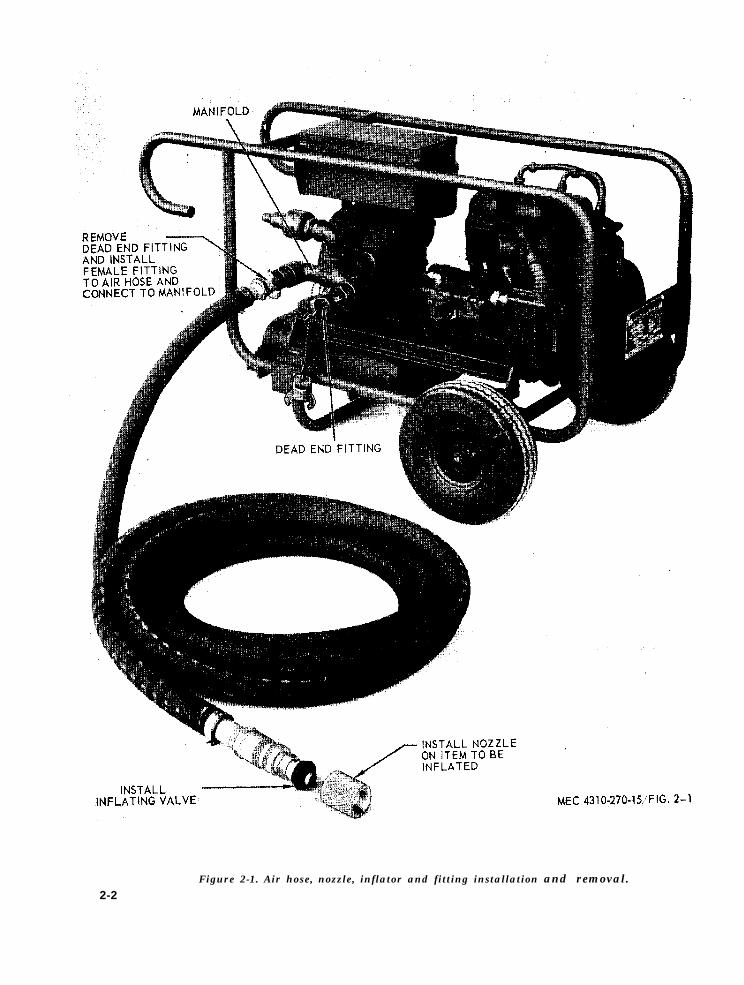
Figure 2-1. Air hose, nozzle, inflator and fitting installation and removal.2-2

C. The engine starting rope is used as de-scribed in figure 2-3.
d. The hose strap is used as illustrated infigure 1-1.
2-5. Installation or Setting-up Instructions
a. General. This rotary compressor is a por-table, self-contained unit designed to operateunder severe conditions.
b. Outdoor Installation. Set up rotary com-pressor as level as possible. If a hard surfaceis used, the wheels must be chocked.
Caution: The rotary compressor should nev-er be operated more than 15 degrees off level.
c. Assemble the hose, inflating valve and con-nect to male fitting on the manifold. Installnozzle on item to be inflated, (fig. 2-1).
d. Indoor Installation. Provide for at leasttwo feet of excess space on all sides of theunit. Make sure the enclosure is well ventilat-ed. Install gas-tight exhaust pipe extensionsto carry exhaust fumes to the outside. Wrapthe exhaust pipes with asbestos if there isdanger of any one touching them.
Warning: Do not operate rotary compressorin an enclosed area unless exhaust gases arepiped to the outside. Inhalation of exhaustfumes will result in serious illness or death.
Section II. MOVEMENT TO NEW WORK SITE
2-6. Dismantling for Movement d. Store inflating valves, and nozzle in toolbox.
a. Shut down and disconnect inflating valve e. The rotary compressor is a portable unitfrom nozzle. and can be readily moved by manpower from
b. Disconnect nozzle from system being in- one site to another,
flated. 2-7. Re-installation After Movement
c. Disconnect air hose from manifold and Set up the rotary compressor for operationcoil around frame, secure with hose strap as in accordance with instructions in paragraphshown in figure 1-1. 2-5.
Section III. CONTROLS AND INSTRUMENTS
2-8. General 2-9. Controls
This section describes, locates, illustrates The purpose of controls and their normaland furnishes operator, crew or organization positions are illustrated in figure 2-2 and en-maintenance personnel sufficient information gine TM 5-2805-208-14, figure 6.about various controls and instruments forproper operation of the rotary compressor.
2-3

Figure 2-2. Controls.
2-4

2-10. General
Section IV. OPERATION OF EQUIPMENT
2-11. Starting
a. Instructions in this section are published a. Preparation For Starting:for information of the rotary compressor. (1)
b. The operator must know how to performevery operation of which the rotary compres- (2)sor is capable. This section gives instructionson starting and stopping the rotary compres-sor, basic motions of the rotary compressor, (3)and on coordinating basic motions to performspecific tasks for which the equipment is de- (4)signed. Since nearly every job presents a dif-ferent problem, the operator may have to varygiven procedures to fit the individual job.
Perform the daily preventive mainte-nance services, (para 3-6).Lubricate the rotary compressor inaccordance with the current lubrica-tion order.Lubricate engine in accordance withLO 5-2805-208-14.If the engine is new or rebuilt or ifthe fuel filter has been serviced, re-move fuel filter sediment bowl, fillwith gasoline and replace. This willsave repeated cranking of engine re-quired to pump gasoline from the fueltank to the sediment bowl.
b. Starting: Refer to figure 2-3 and startthe rotary compressor.
2-5

2-6 Figure 2-3. Engine starting procedure.

c. When engine warms up pull inlet temper-ature control handle out for temperaturesabove 50 degrees F. Push handle in for tem-peratures below 25 degrees F. Place handlehalfway in for temperatures between 25 de-grees F and 50 degrees F.
2-12. Stopping
a. Refer to figure 2-4 and stop the rotarycompressor.
Figure 2-4. Stoppage Engine.
b. Perform the necessary daily preventivemaintenance service.
2-13. Operation Under Usual Conditions
a. It is essential that the operator know howto perform every operation of which the ro-tary compressor is capable. Perform the dailypreventive maintenance services, (para 3-6).
b. Start the rotary compressor as describedin figure 2-3.
c. Stop rotary compressor as described infigure 2-4.
d. When the engine is operating, the airblower is directly driven at a preset pressureand no further operations need be performedother than the desired connection of either 1or 2 hoses. The air hose and fittings may beconnected and disconnected when the rotarycompressor is operating.
2-13. Operation in Extreme Cold (Below0° F)
a. Refer to current lubrication order forproper grade of lubrication.
b. Keep the fuel tank as full as possible andrefill after operation to prevent condensationfrom forming within the tank.
c. Clean the fuel filter sediment bowl morefrequently than usual.
d. Clean snow and ice from lubricationpoints before lubricating.
e. Inlet temperature handle must be pushedall the way in for temperatures below 25 de-grees F.
2-14. Operation in Extreme Heat
a. Refer to current lubrication order for theproper grade of lubricants. Lubricate engine asdescribed in LO 5-2805-208-14.
b. Check the air shrouds of the engine forinsufficient ventilation of the engine. Cleanair shrouds at regular intervals.
c. Inlet temperature handle must be pulledall the way out for temperatures above 50 de-grees F.
d. The blower air filter must be kept cleanor replaced more frequently.
2-15. Operation in Dusty or Sandy Areas
a. Lubricate unit in accordance with the cur-rent lubrication order and LO 5-2805-208-14.Keep lubricants free of dust and sand. Keeplubrication points, and lubrication equipmentclean.
b. Service engine air cleaner, sedimentbowl, and blower air filter more frequently thanduring normal operation.
c. Provide adequate protection to keep sandand dirt from entering fuel tank when filling.Service fuel filter as often as necessary tokeep it free of foreign matter.
d. Protect rotary compressor from dust andsand by locating it near natural barriers and bywetting down the surrounding terrain if wateris plentiful.
e. Clean the unit at frequent intervals withan approved cleaning solvent or compressedair.
f. Cover the unit when not in operation.
2-7

2-16. Operation Under Rainy or HumidConditions
a. Protect the unit with a shelter of somekind. Keep the sides open for ventilation.
b. Make sure all surfaces requiring lubrica-tion are clean and dry before applying lubri-cation. Lubricate in accordance with currentlubrication order.
c. Frequently wipe dry all exposed areas.d. Keep fuel tank full, to prevent condensa-
tion.e. Keep the air hose clean and dry. Inspect
frequently for cracks and deterioration.f. Cover the unit when not in operation.
2-17. Operation in Salt Water Areas
a. Wash unit frequently with clean, fresh wa-ter. Be careful not to contaminate fuel system.
b. Coat exposed metal surfaces with rustproofing material. Remove any rust immediate-ly and apply paint or oil as applicable.
c. Lubricate in accordance with current lu-brication order, and LO 5-2805-208-14.
2-18. Operation in High Altitudes
a. The rotary compressor is designed to op-erate efficiently at elevations up to 5,000 feet.There will be a reduction in efficiency becauseof the rarified air at this level. This is a nor-mal condition that can not be prevented.
b. Keep the air filters clean and unobstruct-ed.
c. Maintain the engine at maximum efficien-cy, check with engine manual TM 5-2805-208-14 for engine service.
2-8
CHAPTER 3OPERATOR AND ORGANIZATIONAL
MAINTENANCE INSTRUCTIONS
Section I. OPERATOR AND ORGANIZATIONAL
MAINTENANCE TOOLS AND EQUIPMENT
3-1. Special Tools and Equipment 3-2. Basic Issue Equipment
No special tools or equipment are required Equipment with, or authorized for use with,by operator or organizational maintenance per- the rotary compressor is listed in the basic is-sonnel for maintenance of the rotary compres- sue items list, appendix B of this manual.sor.
Section II. LUBRICATION
3-3. General Lubrication Information
a. This section contains a reproduction ofthe lubrication order and lubrication instruc-tions which are supplemental to, and not spe-cifically covered in, the lubrication order.
b. The lubrication order shown in figure 3-1is an exact reproduction of the approved lubri-cation order for the rotary compressor. Forthe current lubrication order, refer to DApamphlet 310-4.
3-4. Detailed Lubrication Information
a. General. Keep all lubricants (grease andoil ) in closed containers and stored in a clean,dry place away from heat. Allow no dirt, dust,
water, or foreign material to mix with the lu-bricant at any time. Keep all lubrication equip-ment clean and ready for use.
b. Cleaning. Keep all external parts not re-quiring lubrication clean of lubricants. Be-fore lubricating the equipment, wipe all lubri-cation points free of dirt and grease. Clean alllubrication points after lubrication to preventaccumulation of foreign matter.
c. Points of Application. Detailed lubrica-tion instructions for the engine are containedin TM 5-2805-208-14. Follow the detailed lubri-cation instructions given beneath each illus-trated lubrication point indicated in the currentlubrication order, figure 3-1.
3-1

Figure 3-1. Lubrication order.3-2

d. Operation After Lubrication. Operateunit for five minutes after lubrication. Inspectfor leaks and check oil level in crankcase.Step unit, wait five minutes, and check oillevel again. Add oil if necessary.
e. OES Oil.(1) Crankcase oil level must be checked
frequently as oil consumption mayincrease.
(2) Oil may require changing more fre-quently than usual because contami-nation by dilution and sludge forma-tion will increase under cold weatheroperation conditions.
3-3

Section III. PREVENTIVE MAINTENANCE SERVICE
3-5. General
To insure that the rotary compressor isready for operation at all times, it must be in-spected systematically so that defects may bediscovered and corrected before they result inserious damage or failure. The necessary pre-ventive maintenance services to be performedare listed and described in paragraphs 3-6 and3-7. Item numbers indicate the sequence ofminimum inspection requirements. Defects dis-covered during operation of the unit shallbe noted for future correction, to be made assoon as operation has ceased. Stop operationimmediately if a deficiency is noticed whichwould damage the equipment if operation were
continued. All deficiencies and shortcomingswill be recorded together with the correctiveaction taken on DA Form 2404 (Equipment In-spection and Maintenance Worksheet) at theearliest possible opportunity.
3-6. Daily Preventive Maintenance Service
This paragraph contains an illustrated tabu-lated listing of preventive maintenance serv-ices which must be performed by the opera-tor. The item numbers are listed consecutivelyand indicate the sequence of minimum require-ments. Refer to figure 3-2 for the daily pre-ventive maintenance services.
3-4

PREVENTIVE MAINTENANCE SERVICES
DAILYTM 5-4310-270-15 FULLER MODEL 2MSWB COMPRESSOR, ROTARY AIR
ITEM LUBRICATE IN ACCORDANCE WITH CURRENT LUBRICATION ORDER PAR REF
1. BLOWER GEAR CASE. Check oil level, add oil A/R. 3 -14
2. BLOWER AIR CLEANER. Service as required (weekly). 3-15
3. ENGINE CRANKCASE. Check oil level, add oil A /R. 3 - 9
4 . ENGINE AIR CLEANER INDICATOR. Check for red warning signal. 3 - 9
5 . TIRES. Check tire pressure (maximum air pressure 40 Ibs) (weekly).
6. ENGINE FUEL FILTER. Service as required (weekly). 3 - 1 0
7. FUEL TANK. Added fuel as required.
MEC 431 O-270-15/FIG. 3-2
Figure 3-2. Daily preventive maintenance.
3-5

3-7. Quarterly Preventive MaintenanceService calendar months, or 250 hours of operation,
a. This paragraph contains an illustrated whichever occurs first.tabulated listing of preventive maintenance b. The item numbers are listed consecutivelyservices which must be performed by organiza- and indicate the sequence of minimum require-tional maintenance personnel at quarterly in- ments. Refer to figure 3-3 for the quarterlytervals. A quarterly interval is equal to three preventive maintenance services.
3-6

PREVENTIVE MAINTENANCE SERVICES
Quar ter lyTM 5-4310-270-15 FULLER MODEL 2MSWB COMPRESSOR, ROTARY AIR
ITEM LUBRICATE IN ACCORDANCE WITH CURRENT LUBRICATION ORDER PAR REF
1. GEARCASE OIL DRAIN. Drain after first 500 hr, then every 1500 hrs.
2. OIL LEVEL CHECK. Add oil as required. 3-14
3. RUBBER WASHER. Check for proper sealing. 3-32
4 . AIR RELIEF VALVE. Check for loose parts, adjust when required. 3-31
5. BLOWER AIR FILTER. Service when required every 250 hrs.3-153 -29
6. COUPLING. Check rubber insert, replace if necessary. 5-12
7. ENGINE FUEL FILTER. Service as required.3-103-37
MEC 4310-270-15/FIG. 3-3
F i g u r e 3 - 3 . Q u a r t l y p r e v e n t i v e m a i n t e n a n c e .
3-7

ITEM PAR REF
8. ENGINE SPARK PLUGS. Clean and adjust 0.028 to 0.033 in.
9. ENGINE VALVE TAPPETS, Check clearance, adjust to 0.014 in. 3-44
10. ENGINE OIL DIP STICK. Add oil as required. 3-11
11. AIR CLEANER INDICATOR. Check for red warning signal.
12. ENGINE AIR CLEARNER. Service as required. 3 - 9
13. ENGINE CONTACT ASSEMBLIES. Adjust point gap to 0.018 in. 3-44
14. TIRE. Check tire pressure (maximum 40 Ibs. ).
15. MOUNTING HARDWARE. Check for loose nut and bolts.
16. SECURING CHAIN. Check for damage links and mounting.
17. SHOCK MOUNT. Check for crack and loose hardware. 3-42
18. FUEL TANK. Service strainer, check for loose mounting straps.
MEC 4310-270-15/FIG. 3-3
3-8

Section iV. OPERATOR MAINTENANCE
3-8. General the information and guidance of the operatorInstructions in this section are published for to maintain the rotary compressor.
3-9

Figure 3-4. Operator maintenace.
3-10

3-11
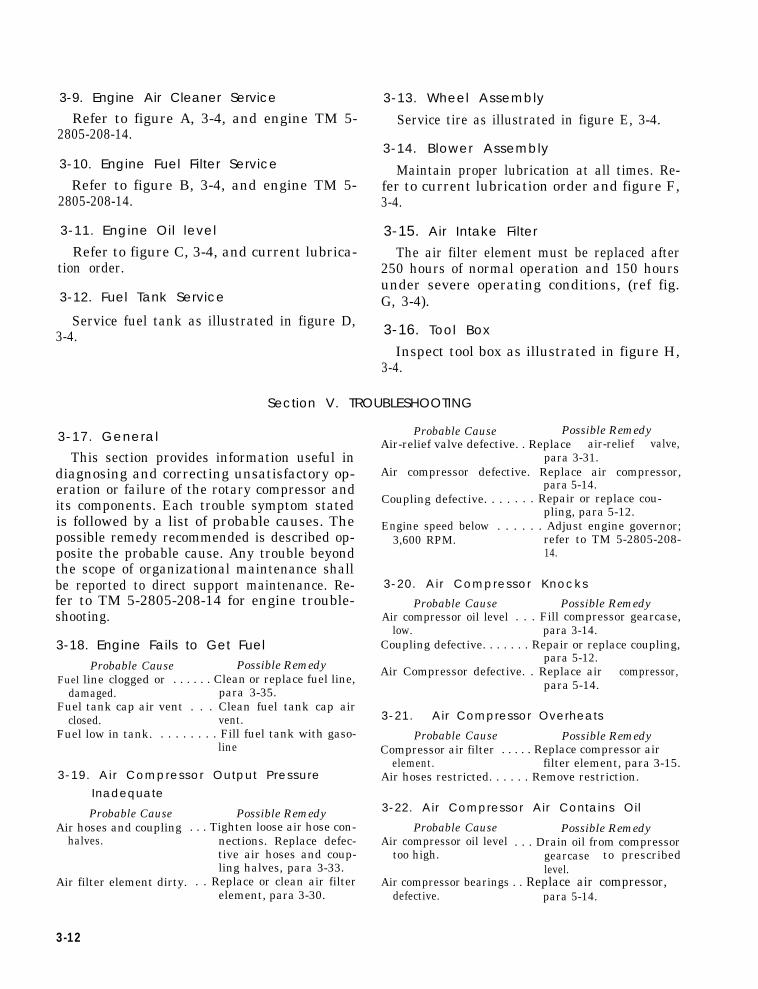
3-9. Engine Air Cleaner Service
Refer to figure A, 3-4, and engine TM 5-2805-208-14.
3-10. Engine Fuel Filter Service
Refer to figure B, 3-4, and engine TM 5-2805-208-14.
3-11. Engine Oil level
Refer to figure C, 3-4, and current lubrica-tion order.
3-12. Fuel Tank Service
Service fuel tank as illustrated in figure D,3-4.
3-13. Wheel Assembly
Service tire as illustrated in figure E, 3-4.
3-14. Blower Assembly
Maintain proper lubrication at all times. Re-fer to current lubrication order and figure F,3-4.
3-15. Air Intake Filter
The air filter element must be replaced after250 hours of normal operation and 150 hoursunder severe operating conditions, (ref fig.G, 3-4).
3-16. Tool Box
Inspect tool box as illustrated in figure H,3-4.
Section V. TROUBLESHOOTING
3-17. General
This section provides information useful indiagnosing and correcting unsatisfactory op-eration or failure of the rotary compressor andits components. Each trouble symptom statedis followed by a list of probable causes. Thepossible remedy recommended is described op-posite the probable cause. Any trouble beyondthe scope of organizational maintenance shallbe reported to direct support maintenance. Re-fer to TM 5-2805-208-14 for engine trouble-shooting.
3-18. Engine Fails to Get FuelProbable Cause Possible Remedy
Fuel line clogged or . . . . . . Clean or replace fuel line,damaged. para 3-35.
Fuel tank cap air vent . . . Clean fuel tank cap airclosed. vent.
Fuel low in tank. . . . . . . . . Fill fuel tank with gaso-line
3-19. Air Compressor Output PressureInadequate
Probable Cause Possible RemedyAir hoses and coupling . . . Tighten loose air hose con-
halves. nections. Replace defec-tive air hoses and coup-ling halves, para 3-33.
Air filter element dirty. . . Replace or clean air filterelement, para 3-30.
Probable Cause Possible RemedyAir-relief valve defective. . Replace air-relief valve,
para 3-31.Air compressor defective. Replace air compressor,
para 5-14.Coupling defective. . . . . . . Repair or replace cou-
pling, para 5-12.Engine speed below . . . . . . Adjust engine governor;
3,600 RPM. refer to TM 5-2805-208-14.
3-20. Air Compressor Knocks
Probable Cause Possible RemedyAir compressor oil level . . . Fill compressor gearcase,
low. para 3-14.Coupling defective. . . . . . . Repair or replace coupling,
para 5-12.Air Compressor defective. . Replace air compressor,
para 5-14.
3-21. Air Compressor Overheats
Probable Cause Possible RemedyCompressor air filter . . . . . Replace compressor air
element. filter element, para 3-15.Air hoses restricted. . . . . . Remove restriction.
3-22. Air Compressor Air Contains Oil
Probable Cause Possible RemedyAir compressor oil level . . . Drain oil from compressor
too high. gearcase to prescribedlevel.
Air compressor bearings . . Replace air compressor,defective. para 5-14.
3-12

para 5-12.
para 3-41.
3 - 2 3 . A i r C o m p r e s o r V i b r a t e s E x c e s s i v e l y
S e c t i o n V I . R A D I O I N T E R F E R E N C E S U P P R E S S I O N
3-24. Definitions
a. Interference. The term “interference” asused herein applies to electrical disturbancesin the radio frequency range which are gen-erated by the rotary compressor and which mayinterfere with the proper operation of radioreceivers or other electronic equipment, or en-able the enemy to locate the equipment.
b. Interference Suppression. The term “in-terference suppression” as used herein ap-plies to the methods used to eliminate or ef-fectively reduce radio interference generatedby the rotary compressor.
3-25. General Methods Used to AttainProper Suppression
Essentially, suppression, is attained by pro-viding a low resistance path to ground straycurrents. Methods used include shielding theignition and high-frequency wire, groundingthe frame with bonding straps, and using ca-pacitors and resistors.
3-26. Interference Suppression Components
a. Primary Suppression Components. Theprimary suppression components are thosewhose primary function is to suppress radio in-terference. These components are describedand located in the engine technical manual, TM5-2805-208-14.
b. Secondary Suppression Components.These components have radio interference sup-pression functions which are incidental and/orsecondary to their primary function, (ref fig.3-5).
Figure 3-5. Radio interference suppression component.
3-27. Replacement of SuppressionComponents
a. Refer to engine TM 5-2805-208-14.b. Replace ground cable as illustrated in
figure 3-5.
3-28. Testing of Radio Interference Sup-pression Components
Test the capacitors for leaks and shorts on acapacitor tester; replace defective capacitors.If test equipment is not available and inter-ference is indicated, isolate cause by the trial-and-error method of replacing each capacitorin turn until the cause of interference is locat-ed and eliminated.
3-13

Section VII. AIR INTAKE AND DISCHARGE SYSTEM
3-29. General ever pressure in the air compressor risesThe air intake system of the rotary com- above 6.8 psi.
pressor consists of a blower air filter mount-ed on the right side of the air blower. The air 3-30. Blower Air Filterdischarge system is comprised of a manifold a. Removal.and air relief valve. Connected to the manifold (1) Remove the weather hood and ele-are two air hoses used for inflating. The air ment as illustrated in figure 3-6.relief valve is preset to discharge air when-
Figure 3-6. Blower air filter removal and installation.
(2) If required, remove filter base. 3-31. Air Relief Valveb. Cleaning. Clean and inspect, replace ele- a. Removal. Remove air relief valve from
ment as required. 90 degree elbow, (ref fig. 3-7).c. Installation. Install the air filter as illus-
trated in figure 3-6.
3-14

3-15
Figure 3-7. Air relief valve and quick disconnectfitting removal and installation.
b. Cleaning and Inspection.(1) Clean air relief valve with an ap-
proved solvent.(2) Inspect for damaged threads, cracks,
and other damage.c. Installation. Install the air relief valve as
illustrated in figure 3-7.
3-32. Quick Disconnect Fittings
a. Removal.(1) Remove dead-end fitting, remove
safety chain if required, figure 3-7.(2) Remove male fitting from the mani-
fold, figure 3-7.(3) Remove rubber
3-34. General
The rotary compressor
washer from both
dead-end and male fittings.b. Cleaning and Inspection.
(1) Clean both dead-end and male fittingswith an approved solvent.
(2) Clean rubber washers with an ap-proved solvent.
(3) Inspect both dead-end and male fit-tings for excess wear on the lockinglugs, cracks, and damaged threads.
(4) Inspect the rubber washers for cracksand excess wear.
c. Installation.(1) Insert the rubber washers into the
fittings.(2) Thread the male fitting into the man-
ifold.(3) Twist and lock dead-end fitting into
the male fitting. If the dead-end fit-ting will not lock and is loose, replacerubber washers.
(4) Secure safety chain to manifold.
3-33. Hose Assemblya. Removal.
(1) Remove female fitting.(2) Remove hose clamps.(3) Remove hose adapters.
b. Cleaning and Inspection.(1)
(2)
(3)
Clean all metal components with anapproved solvent.Clean the air hose with an approveddetergent.Inspect all components for rust,cracks, and other damage. Checkrubber washer for excess wear.
c. Installation.(1) Insert adapter into ends of hose.(2) Secure adapter with hose clamps.(3) Thread female fitting into one end
of each hose.
Section VIII. FUEL SYSTEM
attached to the fuel tank outlet and to the
is equipped with a engine fuel filter, (fig. 3-8).
2 1/2 gallon fuel tank made of 18-gage terne- 3-35. Fuel lineplate. A removable wire mesh strainer is lo-cated at the neck of the tank. The fuel tank a. Removal. Refer to figure 3-8 for remov-cap is vented and attached to the tank with al of the fuel line.a safety chain. A 1/4 inch nylon fuel line is

Figure 3-8. Fuel line removal and installation.3-16

b. Cleaning and Inspection.(1) Clean fuel line and fitting with an
approved solvent.(2) Inspect fuel line for cracks and de-
terioration.c. Repair. As a field expedient repair, in
the event the fuel line becomes cut or broken,pressure-sensitive tape may be wound aroundthe break in the fuel line.
d. Installation. Install fuel line as shown infigure 3-8.
3-36. Fuel Tank
a. Removal.(1) Remove fuel line at tank end and
drain into suitable container.(2) Remove 1/4-20 nuts and screws as
shown in figure 3-8.(3) Remove strainer and cap gasket as
shown in figure A, 3-9.
3-17

Figure 3-9. Fuel tank removal and installation.3-18

b. Cleaning and Inspection.(1) Clean fuel tank with an approved solv-
ent. Fill tank and check for leaks.(2) Clean tank strap with an approved
solvent. Do not soak tank strap insolvent. Avoid solvent contact onstrap felt. If felt becomes deterio-rated, replace.
(3) Clean strainer with an approved solv-ent. Inspect the wire mesh for obstruc-tions, cracks, and deterioration.
(4) Clean and inspect fuel tank cap. Re-place gasket if deteriorated, (fig. A,3-9).
c. Installation.(1) Replace fuel strainer and cap on tank.(2) Position fuel tank straps, top and bot-
tom, at the fuel outlet end. From thebottom side insert 1/4-20 screwthrough a 14 flat washer, bottomstrap, mounting bracket, top strap,
flat washer, and lock washer. Screw1/4-20 nut only a few turns, (fig. B,3-9) .
(3) Insert the fuel outlet end of the fueltank through the top and bottommounting straps. Finger tighten hard-ware, (fig. B, 3-9).
(4) Level fuel tank and mount top andbottom mounting straps at the inletend. Assemble the hardware as pre-viously stated and finger tighten,(fig. B, 3-9).
(5) Position fuel tank as illustrated in fig-ure B, 3-9, and tighten hardware,making certain that a gap is main-tained between the sides of the fueltank and the inside edge of all fourmounting brackets.
3-37. Engine Fuel Filter
a. Removal. Remove as shown in figure 3-10.
3-19

Figure 3-10. Engine fuel filter removal and installation.
(1) Remove(2) Remove(3) Remove(4) Remove
fuel line nut and sleeve.90 degree elbow.sediment bowl.engine fuel filter, making
certain the 1/4 NPT by 1 1/2 LG nip-ple is retained on the engine fuelpump.
b. Cleaning and Inspection. Refer to engineTM 5-2805-208-14.
c. Installation(1) Screw fuel filter into 1/4 NPT by 1-
1/2 LG nipple.(2) Replace sediment bowl.(3) Replace 90 degree elbow.(4) Replace fuel line nut and sleeve.
3-38. Engine Fuel Pump
Refer to engine TM 5-2805-208-14.
3-20

Figure 3-12.
Section IX. TIRES, TUBES AND WHEELS
3-39. General
The rotary compressor is equipped with twopneumatic tube-type tires mounted on 3/4 inchdiameter spindles. The wheels are equippedwith ball bearings which are lubricated throughgrease fittings located on the inner wheel half.
3-40. Wheel Assembly
a. Removal.
(1) Remove wheel from axle spindle asshown in figure 3-11.
(2) Disassemble wheel as illustrated infigure 3-12.
Figure 3.11. Wheel removal and installation.
b. Cleaning and Inspection.(1) Clean inner and outer wheel halves,
bearings and hardware in an approved (2)
solvent. Inspect parts for cracks, cor-rosion, and other damage.Clean tires and inspect for cracks,
3-21

excess wear and deterioration. c. Installation.(3) Clean tube; inflate and inspect for (1) Reassemble wheels, tire, and tube as
leaks. Repair or replace tube as re- illustrated in figure 3-12.quired. (2) Install on rotary compressor is illus-
trated in figure 3-14.
Section X. VIBRATION AND SHOCK INSULATION
3-41. General
The engine and blower frame are mountedon four elastomer shock mounts. Theseshock mounts are fastened to the rotary com-pressor frame and provide protection againstshock loads imposed on the unit and reduceengine vibration to a minimum.
3-42. Shock Mounts
a. Removal. Remove shock mounts as illus-trated in figure 3-13.
Figure 3-13. Shock mounts removal and installation.
b. Cleaning and Inspection. Clean and inspectshock mounts for cracks and deterioration.
c. Installation. Install shock mounts as illus-trated in figure 3-13.
Section XI. FRAME
3-43. General (1) Remove blower, paragraph 5-14.(2) Remove engine, paragraph 5-13.The frame is of an all-welded construction (3) Remove blower and engine frame,and fabricated of steel tubing. The structure figure 3-14.is braced and provision is made for shockproof (4) Removemounting of the engine and blower frame as- 42.sembly. (5) Remove
a. Removal. (6) Remove
3-22
shock mounts, paragraph 3-
fuel tank, paragraph 3-36.wheels, paragraph 3-40.

Figure 3-14. Frame disassembly and reassembly.3-23

c. Cleaning and Inspection. (2)(1) Clean frame with an approved sol- (3)
vent.(2) Inspect for cracks, rust and mis- (4)
alignment, Remove rust and repaint (5)if required. (6)
d. Reassembly. (7)(1) Assemble wheels, figure 3-14. (8)
Assemble shock mounts, figure 3-14.Assemble blower and engine frame,figure 3-14.Mount blower, paragraph 5-14.Mount engine, paragraph 5-13.Align coupling, paragraph 5-12.Mount fuel tank, paragraph 3-36.Assemble fuel line, paragraph 3-35.
Section XII. POWER PLANT
3-44. General
The military engine used on the rotary com- engine will develop 3 HP at 3600 RPM. For allpresser is a 4-stroke cycle, overhead valve, air- Operator and Organizational Maintenance In-cooled engine. This engine is fully radio in- struction, refer to Engine Technical Manualterference suppressed and fungus-proofed. The TM 5-2805-208-14.
3-24

4-1
CHAPTER 4
DIRECT AND GENERAL SUPPORT ANDDEPOT MAINTENANCE INSTRUCTIONS
Section I. GENERAL
4-1. Scope 4-2. Records and Report Forms
These instructions are published for the use For record and report forms applicable toof direct and general support and depot main- direct and general support and depot mainte-tenance personnel maintaining the Fuller mod- nance, refer to TM 38-750.el 2MSWB compressor, rotary air. They pro- Note. Applicable forms, excluding Standard Formvide information on the maintenance of the 46, which is carried by the operator, shall be kept inequipment, which is beyond the scope of tools, a canvas bag mounted on equipment.equipment, personnel, or supplies normallyavailable to using organizations.
Section II. DESCRIPTION AND TABULATED DATA
4-3. Description overhaul data pertinent to direct and general❑
For a complete description of the compres- support and depot maintenance personnel.
sor, rotary air, 60 CFM, 5.6 P. S. I., see para- b. Overhaul Data. For all overhaul data
graph 1-3. pertinent to direct and general support of theengine at this level, refer to TM 5-2805-208-14.
4-4. Tabulated Data c. Compressor repair and replacement stand-
a. General. This paragraph contains all theards. Refer to table 4-1.
Table 4-1. Compressor Repair and Replacement Standards
Component
Cylinder BoresInside diameter
Cylinder to impellerclearance
IMPELLERSLength tip-to-tipImpeller diameterClearance between
impellersTotal clearance between
imp. hub and endcover
SPUR GEARSBacklash
Minimum
4.250
2.9962.244
Maximum
4.252
2.9954.243
Desired clearances
Minimum
0.003
0.005
0.003
0.0015
Maximum
0.004
0.011
0.005
0.0050
Maximum allowablewear and clearance


CHAPTER 5
GENERAL MAINTENANCE INSTRUCTIONS
Section I. SPECIAL TOOLS AND EQUIPMENT
5-1. Special Tools and Equipment 5-2. Specially Designed Tools and
No special tools or equipment are required Equipmentby direct and general support and depot main- No specially designed tools or equipmenttenance personnel for performing maintenance are required by direct and general supporton the rotary compressor. and depot maintenance for performing main-
tenance on the rotary compressor.
Section II. TROUBLE SHOOTING
5-3. General
This section provides information useful inthe diagnosing and correcting unsatisfactoryoperation or failure of the rotary compressoror any of its components. Each trouble symp-tom stated is followed by a list of probablecauses. The possible remedy recommended isdescribed opposite the probable cause. Forengine field and depot maintenance trouble-shooting, refer to TM 5-2805-208-14.
5-4. Air Compressor Output PressureInadequateProbable Cause Possible Remedy
Air-relief valve defec- . . . . Adjust or replace air-tive or out of adjust- relief valve, para 5-10.ment.
Probable Cause Possible RemedyDefective hose fitting . . . . Replace hose fitting gasket.
gasket.
5-5. Air Compressor KnocksProbable Cause Possible Remedy
Impellers are damaged. . . . Replace impellers, para6-6.
Spur gears are dam- . . . . Replace spur gears, paraaged. 6-4.
Impeller bearings are . . . Replace impeller bearings,damaged. para 6-5.
5-6. Air Compressor Air Contains OilProbable Cause Possible Remedy
Air compressor bearing . . . Replace air compressorseals leaking. bearings, para 6-5.
Gear case air vent . . . . . . Clean vent.plugged.
Section III. RADIO INTERFERENCE SUPPRESSION
5-7. General 5-8. Interference Suppression Components
Refer to TM 11-483 for definitions, pur- Refer to engine TM 5-2805-208-14.poses, source and methods used to obtainproper suppression.
Section IV. REMOVAL AND INSTALLATIONOF MAJOR COMPONENTS
5-9. General 5-10. Air Relief Valve
The rotary compressor consists of several a. Maintenance and service beyond adjust-major components; the air blower, engine, ment is not recommended. Should the air-re-shaft coupling, and air relief valve. lief valve not function properly after the best
possible service and adjustment, replace thevalve.
5-l

b. Adjustment.(1)
(2)
(3)
(4)
(5)
(6)
(7)
To adjust air-relief valve, remove90 degree elbow.Install a one inch tee with the use ofa close nipple.Install the air-relief valve at one portand a pressure gauge at the other.Install both deadend fittings to themanifold.Start Engine. The pressure gaugeshould indicate 7.5 P.S.I. and the air-relief valve should be fully opened.Remove the deadend fittings on themanifold; the pressure gauge shouldindicate 6.5 P.S.I. with no leakagefrom the air-relief valve.To adjust the air-relief valve, removethe hood and loosen the lock nut andturn the adjusting screw counter-clockwise until operational pressureis 6.5 P.S.I. and the relief pressureis 7.5 P.S.I. as shown by figure 5-1.
Figure 5-1. Air relief valve adjustment.
5-2

Figure 5-2.
5-11.
FIGURE 5-2
Figure 5-2. Manifold removal and installation.
b. Installation 5-12. Coupling(1) Install manifold on compressor. a. Removal(2) Position compressor on the mounting
(3)(4)
plate, assemble and align coupling, (1)figure 5-3. (2)
Secure compressor.Install components as illustrated in (3)
figure 5-2.
Disconnect ground cable, figure 3-5.Disconnect components as illustratedin figure 5-4.Disassemble coupling as shown in fig-ure 5-3.
5-3

Figure 5-3. Coupling disassembly and reassembly.
5-4

Figure 5-4. Coupling removal and
b. Installation. (4)
(1)
(2)
(3)
Install 5/8 bushing and half couplingto compressor shaft. (5)Install 3/4 bushing and half couplingto engine shaft. (6)Install rubber insert on air compres- (7)sor side.
installation.
Position engine and partly securehardware.Align coupling, figure 5-3, allowingno more than 2 degree misalignment.Secure engine.Assemble components as illustratedin figure 5-4 and figure 5-5.
5-5

Figure 5-5. Engine removal and ins ta l la t ion .
5-6

5-13. Engine 5-14. Air Compressora. Remove and install engine as described Remove and install air compressor as de-
in paragraph 5-12, figure 5-4. scribed in paragraph 5-11.b. Refer to engine technical manual for re-
moval of all engine major components (TM5-2805-208-14).
5-7


CHAPTER 6
COMPRESSOR REPAIR INSTRUCTIONS
6-1. General
The air compressor has two figure eight im-pellers rotating in opposite directions. As eachlobe of an impeller passes the blower inlet, ittraps a quantity of air equal to exactly one-fourth the displacement of the compressor.This entrapment occurs four times per revo-lution, moving the entrained air around thecase to the blower outlet. Timing gears accu-rately position the impellers in relation to eachother, maintaining the minute clearances sovital to the high volumetric efficiency of therotary positive blower.
6-2. Determining Proper ImpellerClearances
a. The clearances between impellers aremeasured at points 0-0 and c-c when the im-pellers are in the position shown in figure 6-1.The impellers are viewed from the drive endof the blower; always face the drive shaftwhen determining clearances.
Figure 6-1. Determining proper impeller clearance.
b. To Determine Total Clearance.(1)
(2)
(3)
(4)
c. To
Place the impellers in the 0-0 posi-tion, figure 6-1.Measure the distance between 0-0with a feeler gauge, figure 6-1.Rotate the impellers 90 degrees toposition c-c and measure distance be-tween c-c.Add measurements 0-0 and c-c fortotal clearance. Desired clearance.005-.011.Determine Correct Clearance. Divide
the total clearance evenly between points 0-0and c-c.
6-3. Resetting Impeller Clearance
a. Impellers are held in time by taper pinswhich secure the shaft and timing gears. Tore-time, it is necessary to remove only one ta-per pin, (fig. 6-2).
(1)
(2)(3)
(4)
(5)
(6)
Insert a short length of pipe over theshaft, clearing the taper pin, anddrive the timing gear further into theshaft. This will loosen the taper pin,(fig. 6-3).Remove the taper pin, (fig. 6-4).With a gear puller, pull the gearaway from the blower so that thefront face of the gear is 1/16 of aninch past the front face of the mat-ing gear, figure 6-5.Determine the correct clearance,paragraph 6-2.Insert shim stock of proper thicknessbetween the impellers (because theunit is out of time, it will probably benecessary to wedge the shim stockinto position by rotating the impel-lers).Place a short length against the un-pinned gear and strike the pipe aquick blow. This will drive the gearfurther into the shaft, causing it toturn relative to the shaft because ofthe torque set up by the shim stock,figure 6-3.
6-1

(7) Check clearances, figure 6-1.(8) Repeat procedure until proper clear-
ance is distributed between the im-pellers.
Note. It is not necessar that gear facesline up precisely at the conclusion of thisoperation.
Figure 6-2. Air compressor exploded.
6-2

Figure 6-5.
Figure 6-3. Driving tinting gear further into the shaft. Figure 6-4. Taper pin removal.
Figure 6-6. Bearing and headplate removal gear end.Timing gear removal.
6-3

b. Reassembly.(1)
(2)
(3)(4)
Install taper pin by re-reaming theoriginal hold if the movement be-tween the shaft and gear was neg-ligable. If re-reaming fails to elimi-nate edges set up by retiming, thehole must be re-drilled and reamedfor the next larger size taper pin.Recheck to be sure impeller clear-ances were maintained after taper pinreplacement.Replace gear case.Relubricate (refer to current lubrica-tion order).
6-4. Timing Gears
a. Removal.(1)(2)(3)
(4)(5)
Drain gear case of lubricant.Remove gear case.Remove taper pins by placing a shortlength of pipe over the shaft, clear-ing the taper pin, and drive the tim-ing gear further into the shaft. Thisaction will loosen taper pins, figure6-3.Remove taper pins, figure 6-4.Remove timing gears with a gearpuller, figure 6-5.
b. Cleaning and inspection.(1) Clean gear with an approved solvent.(2) inspect gear for cracked and broken
teeth and excess wear.c. Reassemble.
(1)
(2)(3)
(4)(5)(6)
Install gears to their original posi-tion. Longitudinal taper pin holesmust be aligned.Install taper pin in one gear only.Retime the impeller as described inparagraph 6-3.Install second taper pin.Replace gear case.Lubricate, refer to current lubrica-tion order.
Note. To facilitate positioning, factoryreplacement gears are not drilled. Theseholes must be drilled after the gears are inproper position and the unit has been re-timed.
6-5. Bearings
a. Removal.(1)
(2)(3)(4)(5)(6)(7)
(8)
(9)
Remove compressor from unit, (para5-14).Drain gear case.Secure compressor on work bench.Remove gear case.Remove timing gears, (para 6-4).Remove bearing plate, figure 6-6.Remove 1/4-20 hex head screw ongear end headplate.Remove the gear end headplate bystriking the impeller shafts alternate-ly with a brass punch as shown in fig-ure 6-6. The gearend head plate willseparate from the impeller case.Remove both bearings as shown infigure 6-7.
6-4

Figure 6-7. Bearing removal drive end.
Figure 6-9. Impeller shaft assembly removal.
Figure 6-8. Bearing installation.
6-5
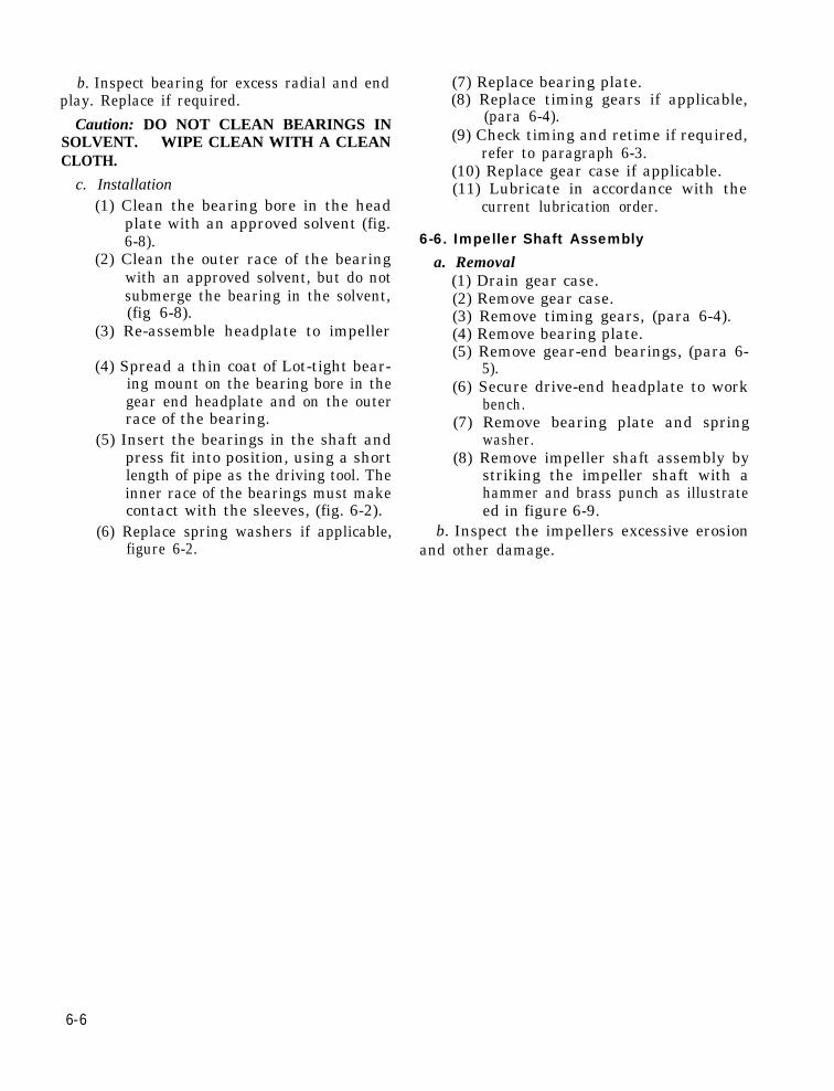
b. Inspect bearing for excess radial and endplay. Replace if required.
Caution: DO NOT CLEAN BEARINGS INSOLVENT. WIPE CLEAN WITH A CLEANCLOTH.
c. Installation(1) Clean the bearing bore in the head
plate with an approved solvent (fig.6-8).
(2) Clean the outer race of the bearingwith an approved solvent, but do notsubmerge the bearing in the solvent,(fig 6-8).
(3) Re-assemble headplate to impeller
(4) Spread a thin coat of Lot-tight bear-ing mount on the bearing bore in thegear end headplate and on the outerrace of the bearing.
(5) Insert the bearings in the shaft andpress fit into position, using a shortlength of pipe as the driving tool. Theinner race of the bearings must makecontact with the sleeves, (fig. 6-2).
(6) Replace spring washers if applicable,figure 6-2.
(7) Replace bearing plate.(8) Replace timing gears if applicable,
(para 6-4).(9) Check timing and retime if required,
refer to paragraph 6-3.(10) Replace gear case if applicable.(11) Lubricate in accordance with the
current lubrication order.
6-6. Impeller Shaft Assembly
a. Removal(1) Drain gear case.(2) Remove gear case.(3) Remove timing gears, (para 6-4).(4) Remove bearing plate.(5) Remove gear-end bearings, (para 6-
5).(6) Secure drive-end headplate to work
bench.(7) Remove bearing plate and spring
washer.(8) Remove impeller shaft assembly by
striking the impeller shaft with ahammer and brass punch as illustrateed in figure 6-9.
b. Inspect the impellers excessive erosionand other damage.
6-6

Figure 6-10.
Figure 6-11. Bearing installation. 6-7

c. Reassembly(1)
(2)
(3)
(4)
(5)
Assemble drive-end headplate to im-peller case, insert dowel pins and (6)fasten headplate with 4 screws only,do not tighten bolts down completely, (7)Insert both impeller shaft assemblies, (8)figure 6-10.Assemble gear-end headplate and in- (9)sert dowel pins.
case with four (4) screws only, donot tighten completely.Assemble bearing plate to gear-endand drive end.Assemble timing gears.Fasten all headplate bolts and torqueto 20 ft. lbs.Time impellers, refer to paragraph6-2.
Insert bearings on both ends, (fig (10) Assemble gear case.6-11). (11) Lubricate in accordance with cur-Fasten gear-end headplate to impeller rent lubrication order.
6-8

APPENDIX A
REFERENCES
A-1. Lubrication
LO 5-4310-270-15 Lubrication Order.LO 5-2805-208-14 Lubrication Order.C 9100-IL Petroleum, Petroleum-Base products and Related Materials.
A-2. Painting
TM 9-213 Painting Instructions for Field Use.
A-3. Preventive Maintenance
TM 38-750 Army Equipment Record Procedures.AR 750-5 Maintenance Responsibilities and Shop Operations.
A-4. Publication Indexes
DA Pam 310-4 Index of Technical Manuals, Technical Bulletins, Supply Manuals(Types 7, 8, and 9), Supply Bulletins, Lubrication Orders, andModification Work Orders.
A-5. Maintenance
TM 5-2805-208-14 Organizational DS and GS Maintenance Manual: (including RepairParts and Special Tool Lists).
TM 5-4310-270-25P Organizational, DS, GS and Depot Maintenance Repair Parts andSpecial Tool Lists.
A-6. Radio Interference Suppression
TM 11-483 Radio Interference Suppression.
A-1


APPENDIX B
BASIC ISSUE ITEMS LIST
Section I. INTRODUCTION
B-1. Scope
This appendix lists items which accom-pany the compressor or are required for instal-lation, operation, or operator’s maintenance.
B-2. General
This bask issue items list is divided into thefollowing sections:
a. Basic Issue Items-Section II. This sec-tion is a listing of accessories, repair parts,tools, and publications required for operator’smaintenance and operation, initially issuedwith, or authorized for the
b . Maintenance and Operating Supplies-Section III. This section is a listing of main-tenance and operating supplies required forinitial operation.
B-3. Explanation of Columns
The following provides an explanation ofcolumns in the tabular list of basic issue items,section II:
a. Source, Maintenance, and RecoverabilityCodes (SMR), Column 1:
(1) Source Code indicates the selectionstatus and source for the listed item.Source codes are:
Code ExplanationP Applied to repair parts which are stocked in
or supplied from GSA/DSA Army supplysystem, and authorized for use at indicatedmaintenance categories.
M Applied to repair parts which are not pro-cured or ticked but are to be manufacturedat indicated maintenance categories.
A Applied to assemblies which are not procuredor stocked as such, but made up of two ormore units, each of which carry individualstock numbers and descriptions and areprocured and stocked and can be assembledby units at indicated maintenance cate-gories.
X Applied to parts and assemblies which arenot procured or stocked, the mortality ofwhich is normally below that of the ap-
Code Explanationplicable end item, and the failure of whichshould result in retirement of the end itemfrom the supply system.
X1 Applied to repair parts which are not pro-cured or stocked, the requirement for whichwill be supplied by use of the next higherassembly or components.
X2 Applied to repair parts which are not stocked.The indicated maintenance category requir-ing such repair parts will attempt to ob-tain them through cannibalization; if notobtainable through cannibalization, suchrepair parts will be requisitioned with sup-porting justification through normal supplychannels.
C Applied to repair parts authorized for localprocurements. If not obtainable from localprocurement, such repair parts will berequisitioned through normal supply chan-nels with a supporting statement of non-availability from local procurement.
G Applied to major assemblies that are pro-
(2)
Code
cured with PEMA (Procurement EquipmentMissile Army) funds for initial issue onlyto be used as exchange assemblies at DSUand GSU level or returned to depot supplylevel.
Note. Source code is not shown on com-mon hardware items known to be readilyavailable in Army supply channels andthrough local procurement.
Maintenance Code indicates the low-est category of maintenance author-ized to install the listed item. Themaintenance level codes are:
ExplanationC Operator/crew.O Organizational Maintenance.
(3) Recoverability Code indicates whetherunserviceable items should be returnedfor recovery or salvage. Items notcoded are expendable. Recoverabilitycodes are:
Code ExplanationR Applied to repair parts and assemblies which
are economically reparable at DSU and
B-1

Code ExplanationGSU activities and are normally furnishedby supply on an exchange basis.
T Applied to high dollar value recoverable re-pair parts which are subject to specialhandling and are issued on an exchangebasis. Such repair parts are normally re-paired or overhauled at depot maintenanceactivities.
u Applied to repair parts specifically selectedfor salvage by reclamation units because ofprecious metal content, critical materials,high dollar value reusable casings andcastings.
b. Federal Stock Number, Column 2. Thiscolumn indicates the federal stock number forthe item.
c. Description, Column 3. This column indi-cates the federal item name and any addi-tional description required. A five-digit man-ufacturer’s or other service code is shown inparentheses followed by the manufacturer’spart number. Repair parts quantities includ-ed in kits, sets, and assemblies that differfrom the actual quantity used in the specificitem, are listed in parentheses following therepair part name.
d. Unit of Issue, Column 4. This column in-dicates the unit used as a basis of issue, e.g.,ea, pr, ft, yd, etc.
e. Quantity Incorporated in Unit Pack, Col-umn 5. This column indicates the actual quan-tity contained in the unit pack.
f. Quantity Incorporated in Unit, Column 6.This column indicates the quantity of the itemused in the equipment.
g. Quantity Furnished With Equipment,Column 7. This column indicates the quantityof an item furnished with the equipment inexcess of the quantity incorporated in the unit.
h. Quantity Authorized, Column 8. This col-umn indicates the quantity of an item author-
ized the operator/crewobtain as required. Asdicated with an asterisk.
to have on hand or torequired items are in-
i. Illustration, Column 9. This column is di-vided as follows:
(1) Figure number, column 9a, indicatesthe figure number of the illustrationin which the item is shown.
(2) Item number, column 9b, indicatesthe callout number used to referencethe item in the illustration.
B-4. Explanation of Columns in the Tabu-lar List of Maintenance and OperatingSupplies–Section Ill.
a. Item, Column 1. This column containsnumerical sequence item numbers assigned toeach component application to facilitate refer-ence.
b. Component Application, Column 2. Thiscolumn identifies the component applicationof each maintenance or operating supply item.
c. Federal Stock Number, Column 3. Thiscolumn indicates, the federal stock numberfor the item and will be used for requisition-ing purposes.
d. Description, Column 4. This column indi-cates the item and a brief description.
e. Quantity Required for Initial Operation,Column 5. This column indicates the quantityof each maintenance or operating supply itemrequired for initial operation of the equipment.
f. Quantity Required for 8 Hours Operation,Column 6. This column indicates the estimatedquantities required for an average eighthours of operation,
g. Notes, Column 7. This column indicatesinformative notes keyed to data appearing ina preceding column.
B-2

Figure B
-1.
B-
3

Section II.BASIC ISSUE ITEMS LIST
GROUP 31-BASIC ISSUE ITEMSMANUFACTURER INSTALLED
3100-BASIC ISSUE ITEMS
Manufacturer or Depot installedCase, maintenance and operational
manuals: Cotton duck, water repellant, mildew resistant
Manufacturer’s manual operation, organizational, DS, GS, and depot maintenance manual, TM 5-4310-270-15
Department of the Army operation, organizational, direct and general support maintenance manual, TM 5-2805208-14
Hose Assembly Air 1 1/4 x 25 ft(58626) 913-66-3-0773-79
Valve, Inflator (53477) 9927Nozzle, Air (58626) B-7703-1Hose Strap (01344) BN-2468Starter, Assembly Rope
(97403) 9786E121
3200-BASIC ISSUE ITEMSTroop installed or authorizedWrench, open end adjustable, single
head 0 to 1.135 in Jaw opening 10in. long
Extinguisher, fire: dry type charges2 1/2 lb.
B-4

Item
1
2
3
(2)Componentapplication
01 Engine0101 Crank-case
03 Fuel Sys0306 Tank
50 Pneu-matic equip.
6001 Crank-case Block,Cylinder
Crankcase
Section IIIMAINTENANCE AND OPERATING SUPPLIES(3)
Federalstock number
9150-265-9433(2)9150 -265 -9425(2)9150-242-7062(2)
9130-160-1817
9150-231-66399150-985-72329150-985-7234
(4)
Description
Oil Lubricating:1 qt. sealedcan as follows:
OE30OE10OESFuel, gasoline
5 gal. can asfollows:
Gasoline, automotive combat
Oil lubricating:5 gal drum asfollows :
Grade 2190Grade 2075THGrade 211TH
(5)Qty rodf/initial
oper.
5/8 qt
2.5 gals(4)
(6)
Qty rodf/8 hrs
oper.
(3)
2.28gals (4)
(6)
(7)
Notes
(1) Includes qty of oil tofill engine oil system asfollows :
5/8 qt crankcase(2) See C9100-1L for ad-
ditional data and requisi-tioning procedure.
(3) See current LO forgrade application andreplenishment intervals
(4) Tank capacity
(5) Average fuel con-sumption is .285 gals perhour of continuous oper-ation.
(6) Includes quantity ofoil to fill compressor oilsystem as follows:
approximately 1/2 pt.in crankcase.
B-5


APPENDIX C
MAINTENANCE ALLOCATION CHART
Section l. INTRODUCTION
C-1. General
a. This section provides a general explana-tion of all maintenance and repair functionsauthorized at various maintenance levels.
b. Section II designates overall responsibil-ity for the performance of maintenance oper-ations on the identified end item or compo-nent. The implementation of the maintenancetasks upon the end item or component will beconsistant with the assigned maintenance op-erations.
c. Section III lists the special tools and testequipment required for each maintenance op-eration as referenced from section II.
d. Section IV contains supplemental instruc-tions, explanatory notes and/or illustrationsrequired for a particular maintenance function.
C-2. Explanation of Columns in Section II
a. Functional Group Number. The function.al group is a numerical group set up on a func-tional basis. The applicable functional groupingindexes (obtained from TB 750-93-1, Func-tional Grouping Codes) are listed on the Main-tenance Assignment in the appropriate numer-ical sequence. These indexes are normally setup in accordance with their function and prox-imity to each other.
b. Component Assembly Nomenclature. Thiscolumn contains a brief description of thecomponents of each functional group.
c. Maintenance Functions and MaintenanceCategories. This column lists the variousmaintenance functions (A through K) and in-dicates the lowest maintenance category au-thorized to perform these operations. Thesymbol designations for the various mainte-nance categories are as follows:
C-Operator or crewO-Organizational maintenanceF-Direct support maintenanceH-General support maintenanceD-Depot maintenance
The maintenancelows :A-INSPECT :
B-TEST:
C-SERVICE :
D-ADJUST :
E-ALINE :
F-CALIBRATE :
G-INSTALL :
H-REPLACE :
I-REPAIR :
functions are defined as fol-
Verify serviceability and detectincipient electrical or mechanicalfailure by close visual examina-tion.
Verify serviceability and detectincipient electrical or mechanicalfailure by measuring the me-chanical or electrical character-istics with authorized standards.Tests will be made commensur-ate with test procedures andwith calibrate tools and/or teatequipment referenced in theMaintenance Assignment.
Operations required periodicallyto keep the item in proper oper-ating condition, i.e., to clean,preserve, drain, paint, and re-plenish fuel, lubricant, hy-draulic, and deicing fluids, orcompressed air supplies.
Regulate periodically to preventmalfunction. Adjustments willbe made commensurate with ad-justment. procedures and as-sociated equipment adjustmentspecifications.
Adjust two or more components ofan electrical or mechanical systam so that their functions areproperly synchronized or ad-justed.
Determine, check, or rectify thegraduation of an instrument,weapon, or weapons system orcomponent of a weapons sys-tem.
Remove and install the same itemfor service or when required forthe performance of other main-tenance operations.
Substitute serviceable components,assemblies and sub-assembliesfor unserviceable counterparts.
Restore to a serviceable conditionby replacing unserviceable partsor by any other action requiredusing available tools, equipmentand skills, including welding,
C-1

J-OVERHAUL:
K-REBUILD:
d. Reference
grinding, riveting, straighten-ing, adjusting and facing.
Restore an item to a completelyserviceable condition (as pre-scribed by serviceability stand-ards developed and published bythe commodity commands) byemploying techniques of “Inspectand Repair Only as Necessary”(IROAN). Maximum use ofdiagnostic and test equipment iscombined with minimum disas-sembly during overhaul. “Over-haul” may be assigned to anylevel of maintenance except or-ganizational, provided the time,tools, equipment, repair partsauthorizational, and technicalskills are available at that level.Normally, overhaul as appliedto end items is limited to depotmaintenance level.
Restore to a condition compara-bly to new by disassembling todetermine the condition of eachcomponent part and reassem-bling using serviceable, rebuilt,or new assemblies, subassem-blies, and parts.
Note. This column, subdividedinto columns L and M, is provided for refer-encing the special tool and test equipment re-quirements (sec. III) and remarks (sec. IV)that may be associated with maintenance.functions (sec. II).
C-3. Explanation of Columns in Section III
a. Reference Code. This column consists ofa number and a letter separated by a dash.The number references the T and TE require-ments column on the Maintenance Assignment.The letter represents the specific maintenancefunction the item is to be used with. The let-ter is representative of columns A through Kon the Maintenance Assignment.
b. Maintenance Category. This columnshows the lowest level of maintenance author-ized to use the special tool or test equipment.
c. Nomenclature. This column lists the nameor identification of the tool or test equip-ment.
d. Tool Number. This column lists the man-ufacturer’s code and part number, or federalstock number of tools and test equipment.
C-5. Explanation of Columns in Section IV
a. Reference Code. This column consists oftwo letters separated by a dash, both of whichare references to section II. The first letterreferences column M and the second letterreferences a maintenance operation, columnsA through K.
b. Remarks. This column lists informationpertinent to the maintenance operation beingperformed, indicated on the Maintenance As-signment section II.
C-2

Section II. MAINTENANCE ASSIC$NMENT— —.
18o$a:0 5p
010100
0102
030306
060615
131311151501222202
50500050075008
5014
76
7603
Componentassembly
nomenclature
)NGINEEngine Assembly:
Engine, gasoline . . . . . . . . . . . . . . . . . . . . .Crankshaft:
Pulley, crankshaft . . . . . . . . . . . . . . . . . . .‘UEL SYSTEM
Tank, Lines, Fittings:Tank assembly, fuel . . . . . . . . . . . . . . . . . .Line assembly, fuel . . . . . . . . . . . . . . . . . .Strainer assembly, tank . . . . . . . . . . . . . . .
;LECTRICAL SYSTEMRadio Interference Suppression:
Strap, ground . . . . . . . . . . . . . . . . . . . . . . .VHEELS AND TRACKSWheel Assembly . . . . . . . . . . . . . . . . . . . . . . .
~RAMEFrame Assembly . . . . . . . . . . . . . . . . . . . . . .
4CCESSORY ITEMSAccessory Items:
Hose, airInflator, air . . . . . . . . . . . . . . . . . . . . . . . .
‘NEUMATIC EQUIPMENTAir Compressor Assembly . . . . . . . . . . . . . .Compressor Drive Coupling . . . . . . . . . . . .Air Intake Filter Assembly,
Air . . . . . . . . . . . . . . . . . . . . . . . . . . . . . . . . ~Air Receiver Valve &sembly,
Relief . . . . . . . . . . . . . . . . . . . . . . . . . . . . . .URE FIGHTING EQUIPMENT
COMPONENTSFire Extinguishers:
Extinguisher, fire . . . . . . . . . . . . . . . . . ..
_—.-
A—
E~2-1.
c
. .
c. .. .
. .
. .
. .
. .
0. .
. .
. .
c—
1B
0
.
000
0
0
,.
F
0.
,.
0
—
E—
D/●
J3—
c
. .
c
c
c
.,
.,
c.<
c
.,
. .—
Maintenance funcuors
D—
3$?—
,.
. .
,.
. .
. .
. .
. .. .
. .
0
. .—
1‘;E
u::c.—
. .
. .
. .
. .
. .
. .
. .,.
. .
. .
. ._—
F—
yai;,)—
.
,.
,.
. .
,.
,. .. .
,, .
,.
,, .—
G
132-1,.
. .
. .
. .
. .
. .
. .
. .
. .
. .
. .—
—
[
[
Section III. SPECIAL TOOL AND SPECIAL TEST EQUI 3MENT
Note reference
Reference Maintenance
I NomenclatureToId
code level number
No special tools required –
Section IV. REMARKSRef erenee
codeRemarks
A See TM 5-2805-208-14 for remarks. “
“ L
rodsand
quip-rnent
. . . .
M
Re-marks
A
I
C - 3


INDEX
Air compressor:Air contains oil . . . . . . . . . . . . . . . . . . . . . . . . . . . . . . . . . . . . . . . . . . . . . . . . . . . . . . . . . . . . . .Knocks . . . . . . . . . . . . . . . . . . . . . . . . . . . . . . . . . . . . . . . . . . . . . . . . . . . . . . . . . . . . . . . . . . . .
General . . . . . . . . . . . . . . . . . . . . . . . . . . . . . . . . . . . . . . . . . . . . . . . . . . . . . . . . . . . . . . . . . . .Output pressure inadequate . . . . . . . . . . . . . . . . . . . . . . . . . . . . . . . . . . . . . . . . . . . . . . . . . . .Overheats . . . . . . . . . . . . . . . . . . . . . . . . . . . . . . . . . . . . . . . . . . . . . . . . . . . . . . . . . . . . . . . . . . .Repair instructions:
Air compressor . . . . . . . . . . . . . . . . . . . . . . . . . . . . . . . . . . . . . . . . . . . . . . . . . . . . . . . . . . . .General . . . . . . . . . . . . . . . . . . . . . . . . . . . . . . . . . . . . . . . . . . . . . . . . . . . . . . . . . . . . . . . . . .
Tabulated data . . . . . . . . . . . . . . . . . . . . . . . . . . . . . . . . . . . . . . . . . . . . . . . . . . . . . . . . . . . . . . .Vibrates excessively . . . . . . . . . . . . . . . . . . . . . . . . . . . . . . . . . . . . . . . . . . . . . . . . . . . . . . . . . .
Air intake and discharge system:Air hoses . . . . . . . . . . . . . . . . . . . . . . . . . . . . . . . . . . . . . . . . . . . . . . . . . . . . . . . . . . . . . . . . . .Compressor air filter . . . . . . . . . . . . . . . . . . . . . . . . . . . . . . . . . . . . . . . . . . . . . . . . . . . . . . . .General . . . . . . . . . . . . . . . . . . . . . . . . . . . . . . . . . . . . . . . . . . . . . . . . . . . . . . . . . . . . . . . . . . . .Manifold . . . . . . . . . . . . . . . . . . . . . . . . . . . . . . . . . . . . . . . . . . . . . . . . . . . . . . . . . . . . . . . . . . . .Air-relief valve . . . . . . . . . . . . . . . . . . . . . . . . . . . . . . . . . . . . . . . . . . . . . . . . . . . . . . . . . . . . . .
Capacities . . . . . . . . . . . . . . . . . . . . . . . . . . . . . . . . . . . . . . . . . . . . . . . . . . . . . . . . . . . . . . . . . . . . .Cap, fuel tank . . . . . . . . . . . . . . . . . . . . . . . . . . . . . . . . . . . . . . . . . . . . . . . . . . . . . . . . . . . . . . . . .Components, interference suppression . . . . . . . . . . . . . . . . . . . . . . . . . . . . . . . . . . . . . . . . . . .Compressor air filter . . . . . . . . . . . . . . . . . . . . . . . . . . . . . . . . . . . . . . . . . . . . . . . . . . . . . . . . . .Compressor repair and replacement standard . . . . . . . . . . . . . . . . . . . . . . . . . . . . . . . . . . . . .Controls . . . . . . . . . . . . . . . . . . . . . . . . . . . . . . . . . . . . . . . . . . . . . . . . . . . . . . . . . . . . . . . . . . . . . .Corps of engineers identification plate . . . . . . . . . . . . . . . . . . . . . . . . . . . . . . . . . . . . . . . . . . .Coupling shaft . . . . . . . . . . . . . . . . . . . . . . . . . . . . . . . . . . . . . . . . . . . . . . . . . . . . . . . . . . . . . . .
Data, tabulated. (See Tabulated Data)Description and tabulated data . . . . . . . . . . . . . . . . . . . . . . . . . . . . . . . . . . . . . . . . . . . . . . . . . .Differences in models . . . . . . . . . . . . . . . . . . . . . . . . . . . . . . . . . . . . . . . . . . . . . . . . . . . . . . . . . .Dimensions and weight . . . . . . . . . . . . . . . . . . . . . . . . . . . . . . . . . . . . . . . . . . . . . . . . . . . . . . . . .Direct and general support and depot maintenance . . . . . . . . . . . . . . . . . . . . . . . . . . . . . . .
Engine and components:Engine . . . . . . . . . . . . . . . . . . . . . . . . . . . . . . . . . . . . . . . . . . . . . . . . . . . . . . . . . . . . . . . . . . . . .Fuel filter . . . . . . . . . . . . . . . . . . . . . . . . . . . . . . . . . . . . . . . . . . . . . . . . . . . . . . . . . . . . . . . . . .Fuel tank and fuel line . . . . . . . . . . . . . . . . . . . . . . . . . . . . . . . . . . . . . . . . . . . . . . . . . . . . . . .General . . . . . . . . . . . . . . . . . . . . . . . . . . . . . . . . . . . . . . . . . . . . . . . . . . . . . . . . . . . . . . . . . . . . .Data . . . . . . . . . . . . . . . . . . . . . . . . . . . . . . . . . . . . . . . . . . . . . . . . . . . . . . . . . . .: . . . . . . . . . . .Fails to get fuel . . . . . . . . . . . . . . . . . . . . . . . . . . . . . . . . . . . . . . . . . . . . . . . . . . . . . . . . . . . . .Starting . . . . . . . . . . . . . . . . . . . . . . . . . . . . . . . . . . . . . . . . . . . . . . . . . . . . . . . . . . . . . . . . . . .Stopping . . . . . . . . . . . . . . . . . . . . . . . . . . . . . . . . . . . . . . . . . . . . . . . . . . . . . . . . . . . . . . . . . . . .
Equipment:Inspection and maintenance . . . . . . . . . . . . . . . . . . . . . . . . . . . . . . . . . . . . . . . . . . . . . . . . . .Unloading . . . . . . . . . . . . . . . . . . . . . . . . . . . . . . . . . . . . . . . . . . . . . . . . . . . . . . . . . . . . . . . . . . .Unpacking new . . . . . . . . . . . . . . . . . . . . . . . . . . . . . . . . . . . . . . . . . . . . . . . . . . . . . . . . . . . .
Field expedient repairs:Fuel line . . . . . . . . . . . . . . . . . . . . . . . . . . . . . . . . . . . . . . . . . . . . . . . . . . . . . . . . . . . . . . . . . . . .
Filter:Compressor air . . . . . . . . . . . . . . . . . . . . . . . . . . . . . . . . . . . . . . .. . . . . . . . . . . . . . . . . . . . .Fuel tank . . . . . . . . . . . . . . . . . . . . . . . . . . . . . . . . . . . . . . . . . . . . . . . . . . . . . . . . . . . . . . . . . . .
Forms :Field and depot maintenance report . . . . . . . . . . . . . . . . . . . . . . . . . . . . . . . . . . . . . . . . . . . .Operator and organizational maintenance record and report . . . . . . . . . . . . . . . . . . . . .
paragraph
3-223-206-13-193-21
6-26-14-43-23
3-333-303-295-113-31,5-10
1-43-363-263-9,3-294-42-81-45-12
1-3,4-31-51-44-1
3-443-373-35,3-363-443-443-182-112-12
2-32-12-2
3-35
3-303-36
1-24-2
Page
3-123-126-13-123-12
6-16-14-13-13
3-153-303-145-33-14,5-1
1-33-173-133-12,3-144-12-31-35-3
1-1,4-11-41-34-1
3-243-193-15,3-173-243-243-122-52-7
2-12-12-1
3-15
3-143-17
1-14-1
I-1

I-2
Frame . . . . . . . . . . . . . . . . . . . . . . . . . . . . . . . . . . . . . . . . . . . . . . . . . . . . . . . . . . . . . . . . . . . . . . . .Fuel system . . . . . . . . . . . . . . . . . . . . . . . . . . . . . . . . . . . . . . . . . . . . . . . . . . . . . . . . . . . . . . . . . . .Fuel tank and fuel line . . . . . . . . . . . . . . . . . . . . . . . . . . . . . . . . . . . . . . . . . . . . . . . . . . . . . . . .Fuel tank cap, filter . . . . . . . . . . . . . . . . . . . . . . . . . . . . . . . . . . . . . . . . . . . . . . . . . . . . . . . . . . . .
General maintenance instructions . . . . . . . . . . . . . . . . . . . . . . . . . . . . . . . . . . . . . . . . . . . . . . .
Hoses, air . . . . . . . . . . . . . . . . . . . . . . . . . . . . . . . . . . . . . . . . . . . . . . . . . . . . . . . . . . . . . . . . . . . . .
Identification . . . . . . . . . . . . . . . . . . . . . . . . . . . . . . . . . . . . . . . . . . . . . . . . . . . . . . . . . . . . . . . . . .Inspection and servicing of equipment . . . . . . . . . . . . . . . . . . . . . . . . . . . . . . . . . . . . . . . . . . .Installation and operation instructions . . . . . . . . . . . . . . . . . . . . . . . . . . . . . . . . . . . . . . . . . .Interference suppression components . . . . . . . . . . . . . . . . . . . . . . . . . . . . . . . . . . . . . . . . . . . .
Lubrication:Detailed information . . . . . . . . . . . . . . . . . . . . . . . . . . . . . . . . . . . . . . . . . . . . . . . . . . . . . . . . .General information . . . . . . . . . . . . . . . . . . . . . . . . . . . . . . . . . . . . . . . . . . . . . . . . . . . . . . . .
Manifold . . . . . . . . . . . . . . . . . . . . . . . . . . . . . . . . . . . . . . . . . . . . . . . . . . . . . . . . . . . . . . . . . . . . . .Military standard engine:
Identification plate . . . . . . . . . . . . . . . . . . . . . . . . . . . . . . . . . . . . . . . . . . .Models, differences . . . . . . . . . . . . . . . . . . . . . . . . . . . . . . . . . . . . . . . . . . . . .Movement to new worksite . . . . . . . . . . . . . . . . . . . . . . . . . . . . . . . . . . . . . .
Operating of equipment . . . . . . . . . . . . . . . . . . . . . . . . . . . . . . . . . . . . . . . . .Operations:
In dusty or sandy areas . . . . . . . . . . . . . . . . . . . . . . . . . . . . . . . . . . . . . . . . . . . . . . . . . . . . . .In extreme cold (below 0°F. ) . . . . . . . . . . . . . . . . . . . . . . . . . . . . . . . . . . . . . . . . . . . . . . . .In high altitudes . . . . . . . . . . . . . . . . . . . . . . . . . . . . . . . . . . . . . . . . . . . . . . . . . . . . . . . . . . . . .In saltwater areas . . . . . . . . . . . . . . . . . . . . . . . . . . . . . . . . . . . . . . . . . . . . . . . . . . . . . . . . . . .Under rainy or humid conditions . . . . . . . . . . . . . . . . . . . . . . . . . . . . . . . . . . . . . . . . . . . . .Under usual conditions . . . . . . . . . . . . , . . . . . . . . . . . . . . . . . . . . . . . . . . . . . . . . . . . . . . . . .
Operational and organizational maintenance instructions . . . . . . . . . . . . . . . . . . . . . . . .Operator maintenance:
Record and report fonts.... . . . . . . . . . . . . . . . . . . . . . . . . . . . . . . . . . . . . . . . . . . . . . . . . . .Operator’s daily maintenance . . . . . . . . . . . . . . . . . . . . . . . . . . . . . . . . . . . . . . . . . . . . . . . . . . .Organizational maintenance . . . . . . . . . . . . . . . . . . . . . . . . . . . . . . . . . . . . . . . . . . . . . . . . . . . .
Pneumatic tire . . . . . . . . . . . . . . . . . . . . . . . . . . . . . . . . . . . . . . . . . . . . . . . . . . . . . . . . . . . . . . . .Power plant . . . . . . . . . . . . . . . . . . . . . . . . . . . . . . . . . . . . . . . . . . . . . . . . . . . . . . . . . . . . . . . . .Preventive maintenance services:
Daily Preventive maintenance . . . . . . . . . . . . . . . . . . . . . . . . . . . . . . . . . . . . . . . . . . . . . . . .General . . . . . . . . . . . . . . . . . . . . . . . . . . . . . . . . . . . . . . . . . . . . . . . . . . . . . . . . . . . . . . . . . . . . .Organizational . . . . . . . . . . . . . . . . . . . . . . . . . . . . . . . . . . . . . . . . . . . . . . . . . . . . . . . . . . . . . .Quarterly preventive maintenance . . . . . . . . . . . . . . . . . . . . . . . . . . . . . . . . . . . . . . . . . . . . .
Quarterly preventive maintenance . . . . . . . . . . . . . . . . . . . . . . . . . . . . . . . . . . . . . . . . . . . . . .
Radio interference:General methods used to attain proper suppression . . . . . . . . . . . . . . . . . . . . . . . . . . . .Interference suppression components . . . . . . . . . . . . . . . . . . . . . . . . . . . . . . . . . . . . . . . . . .
Removal and installation of major components . . . . . . . . . . . . . . . . . . . . . . . . . . . . . . . . . . .Repair and replacement standards . . . . . . . . . . . . . . . . . . . . . . . . . . . . . . . . . . . . . . . . . . . . . .Repair instructions, air compressor . . . . . . . . . . . . . . . . . . . . . . . . . . . . . . . . . . . . . . . . . . . . .
Scope . . . . . . . . . . . . . . . . . . . . . . . . . . . . . . . . . . . . . . . . . . . . . . . . . . . . . . . . . . . . . . . . . . . . . . . . .Services:
Daily preventive maintenance . . . . . . . . . . . . . . . . . . . . . . . . . . . . . . . . . . . . . . . . . . . . . . . . .Operator maintenance . . . . . . . . . . . . . . . . . . . . . . . . . . . . . . . . . . . . . . . . . . . . . . . . . . . . . . .Quarterly preventive maintenance . . . . . . . . . . . . . . . . . . . . . . . . . . . . . . . . . . . . . . . . . . . . .
Service upon receipt of equipment . . . . . . . . . . . . . . . . . . . . . . . . . . . . . . . . . . . . . . . . . . . . . .
Paragraph3-433-343-35,3-363-36
5-1
3-33
1-42-32-l3-26
3-43-3
5-11
1-41-52-6
2-10
2-152-132-142-182-172-133-1
1-2,4-23-63-1
3-393-44
3-63-53-13-7
3-7
3-253-265-94-46-1
1-1
3-63-83-72-1
Page3-223-153-15,3-173-17
5-1
3-15
1-32-12-13-13
3-13-1
5-3
1-31-42-3
2-5
2-72-72-72-82-82-73-1
1-1,4-13-43-1
3-213-24
3-43-43-13-6
3-6
3-133-135-14-16-1
1-1
3-43-93-62-1

Shock mounts . . . . . . . . . . . . . . . . . . . . . . . . . . . . . . . . . . . . . . . . . . . . . . . . . . . . . . . . . . . . . . . . . .Special tools and equipment . . . . . . . . . . . . . . . . . . . . . . . . . . . . . . . . . . . . . . . . . . . . . . . . . . .Starting engine . . . . . . . . . . . . . . . . . . . . . . . . . . . . . . . . . . . . . . . . . . . . . . . . . . . . . . . . . . . . . . . .Stopping engine . . . . . . . . . . . . . . . . . . . . . . . . . . . . . . . . . . . . . . . . . . . . . . . . . . . . . . . . . . . . .
Tabulated data, field and depot maintenance . . . . . . . . . . . . . . . . . . . . . . . . . . . . . . . . . . . .Tires, tubes, wheels:
General . . . . . . . . . . . . . . . . . . . . . . . . . . . . . . . . . . . . . . . . . . . . . . . . . . . . . . . . . . . . . . . . . . . . .Wheels and tires . . . . . . . . . . . . . . . . . . . . . . . . . . . . . . . . . . . . . . . . . . . . . . . . . . . . . . . . . . . .
Troubleshooting:Air compressor:
Air contains oil . . . . . . . . . . . . . . . . . . . . . . . . . . . . . . . . . . . . . . . . . . . . . . . . . . . . . . . . . . .Knocks . . . . . . . . . . . . . . . . . . . . . . . . . . . . . . . . . . . . . . . . . . . . . . . . . . . . . . . . . . . . . . . . . .Output pressure inadequate . . . . . . . . . . . . . . . . . . . . . . . . . . . . . . . . . . . . . . . . . . . . . . . .
Troubleshooting, operator, and organizational maintenance:Air compressor:
Air contains oil . . . . . . . . . . . . . . . . . . . . . . . . . . . . . . . . . . . . . . . . . . . . . . . . . . . . . . . . . . . .Knocks . . . . . . . . . . . . . . . . . . . . . . . . . . . . . . . . . . . . . . . . . . . . . . . . . . . . . . . . . . . . . . . . . . .Output pressure inadequate . . . . . . . . . . . . . . . . . . . . . . . . . . . . . . . . . . . . . . . . . . . . . . . .
General . . . . . . . . . . . . . . . . . . . . . . . . . . . . . . . . . . . . . . . . . . . . . . . . . . . . . . . . . . . . . . . . . . . . .Tubes . . . . . . . . . . . . . . . . . . . . . . . . . . . . . . . . . . . . . . . . . . . . . . . . . . . . . . . . . . . . . . . . . . . . .
Unloading equipment . . . . . . . . . . . . . . . . . . . . . . . . . . . . . . . . . . . . . . . . . . . . . . . . . . . . . . . . . .Unpacking new equipment . . . . . . . . . . . . . . . . . . . . . . . . . . . . . . . . . . . . . . . . . . . . . . . . . . . . . .
Valve, air-relief . . . . . . . . . . . . . . . . . . . . . . . . . . . . . . . . . . . . . . . . . . . . . . . . . . . . . . . . . . . . . . .Vibration and shock insulation . . . . . . . . . . . . . . . . . . . . . . . . . . . . . . . . . . . . . . . . . . . . . . . . . .
Weight and dimensions . . . . . . . . . . . . . . . . . . . . . . . . . . . . . . . . . . . . . . . . . . . . . . . . . . . . . . . .Wheels and tires . . . . . . . . . . . . . . . . . . . . . . . . . . . . . . . . . . . . . . . . . . . . . . . . . . . . . . . . . . . . . . .
Paragraph3-413-1, 5-12-112-12
4-4
3-393-40
3-223-203-19
5-65-55-45-33-40
2-12-2
3-31, 5-103-41
1-43-40
Page3-223-1, 5-12-52-7
4-1
3-213-21
3-123-123-12
5-15-15-15-13-21
2-12-1
3-14, 5-13-22
1-33-21
I-3

By Order of the Secretary of the Army:
Official:KENNETH G. WICKHAM,Major General, United States Army,The Adjutant General.
HAROLD K. JOHNSON,General, United States Army,Chief of Staff.
Distribution:
Active Army:USASA (2) Army Attaches (1)ACSI (1) Mil Man (1)DCSLOG (1) AMS (3)CNGB (1) MAAG (1)TSG (1) JBUSMC (1)CofEngrs (3) USACOMZEUR (2)CC-E (1) Engr FLDMS (2)Dir of Trans (1) Ft Knox FLDMS (10)CofSptS (1) USA Engr R&D Lab (3)USAMB (1) Fld Cored, DASA (8)USA Arty Bd (2) USAREUR Engr Proc Cen (2)USA Armor Bd (2) - USAREUR Engr SUP Con Agcy (10)USAIB (2) Units org under fol TOE :-2 ea. UNOINDCUSARADBD (2) 5-15USAAESWBD (2) 5-16USAAVNTBD (2) 5-48USCONARC (3) 5-64OS Maj Cored (5) except 6-97
USARJ (1) 5-145USASETAF (2) 5-148USAMC (1) 5-155
USACDCEC (10) 5-237 (5)USAMECOM (46) 5-262 (5)MDW (1) 5-267 (1)
Armies (2) 5-278 (5)corps (2) 5-279
USAC (1) 5-500(EA, EB, HN)
Div (2) 7Engr Bde (1) 29-1
USMA (2) 29-11
Svc Colleges (2) 29-15
Br Svc Sch (2) except 29-16
USAES (3) 29-17
Gen Dep (10) 29-21
Engr Dep (10) 29-25
Army Dep (2) except 29-26
TOAD (3) 29-27
USA Tml Cored (2) 29-35
Army Tml (1) 29-37
Div Engr (2) 37
Engr Dist (2) 39-51Engr Cen (5) 39-61
NG: N o n e .
USAR: Same as Active Army except allowance is one (1) copy for each unit.
For explanation of abbreviations used, see AR 320-50,
U.S. GOVERNMENT PRINTING OFFICE: 1987 0-181-421 (60314)


TM 5-4310-270-15

This fine document...
Was brought to you by me:
Liberated Manuals -- free army and government manuals
Why do I do it? I am tired of sleazy CD-ROM sellers, who take publicly available information, slap “watermarks” and other junk on it, and sell it. Those masters of search engine manipulation make sure that their sites that sell free information, come up first in search engines. They did not create it... They did not even scan it... Why should they get your money? Why are not letting you give those free manuals to your friends?
I am setting this document FREE. This document was made by the US Government and is NOT protected by Copyright. Feel free to share, republish, sell and so on.
I am not asking you for donations, fees or handouts. If you can, please provide a link to liberatedmanuals.com, so that free manuals come up first in search engines:
<A HREF=http://www.liberatedmanuals.com/>Free Military and Government Manuals</A>
– SincerelyIgor Chudovhttp://igor.chudov.com/
– Chicago Machinery Movers