t/m - dticwhere e is the angle between a and the vertical axis. it will be convenient to use,...
TRANSCRIPT
es
© rH 05
a <
r
T/m SYSTEMS GROUP
ONE SPACE PARK • REOONOO BEACH, CALIFORNIA
/ Reproduced by the
f-'-EARINGHOUS«
D D C rrjjESSeilL/TE ^ «us '1989
c
—

ARPA Order 306
HIGH INTENSITY LASER PROPAGATION IN THE ATMOSPHERE
Semiannual Report
1 July 1968 - 30 December 1968
05691-6011-R0-00
Prepared by: Approved by:
LTM. Frantr > S. Altshufer (Project Manager) Theoretical Physics Department Director
Quantum Physics Laboratory
Prepared under Contract N00014-66-C0022
for Office of Naval Research Department of the Navy
Washington, D.C.
This report is part of Project DEFENDER under the joint sponsorship of the Advanced Research Projects Agency, the Office of Naval Research, and the Department of Defense. Reproduction in whole or in part is permitted for any purpose of the United States Government.
This document has been approved for public release and sale; its distribution is unlimited.
Theoretical Physics Department QUANTUM PHYSICS LABORATORY Physical Research Center
TRW SYSTEMS One Space Park
Redondo Beach, California 90278

TABLE OF CONTENTS
Page
1. INTRODUCTION 1
2. THE MODEL EQUATION 4
3. THE METHOD OF SOLUTION 9
4. SPECIAL CASE 14
5. SUMMARY 18
REFERENCES 20
ii
I. INTRODUCTION
The self-defocusing effect Is a phenomenon in which energy is absorbed
by the air from an intense laser beam traversing the atmosphere, with a
resultant decrease in the local refractive index. The region of decreased
refractive index is, in effect, a lens, and may cause the beam to defocus.
In a previous report a study of the self-defocusing effect was
initiated. It was pointed out that there exists the possibility of shaping
the power profile of the laser beam in such a way that, at least initially,
the beam self-focuses instead of self-defocusing. One of the goals of the
study, then, was to determine in detail how the shape of the initial power
profile affects the development of the beam as it progresses through the
atmosphere.
The problem was formulated mathematically in terms of a nonlinear,
partial differential equation, whose solution describes the trajectories
of the rays comprising the beam. In this report we present an approximate
solution to the equation, and obtain from it some qualitative and semi-
quantitative features of the ray trajectories.
The complete nonlinear, partial differential equation has the horizontal
displacement of any given ray as its dependent variable, and contains three
independent variables: time, height, and one horizontal position coordinate
(assuming cylindrical or planar symmetry). The analysis to be discussed here
is in terms of an approximation to the true equation in which the time
appears as a trivial parameter, rather than as an independent variable.
Physically, the approximation is as follows. The change in the refractive
index at any point in space is proportional to the amount of heat deposited.

which in turn is proportional to the energy flux at that point integrated
over time. We have approximated the time integral by the product of the
instantaneous flux and the time. The model is now equivalent to a steady
state situation in which the refractive index has an incremental term pro-
portional to the flux; the coefficient of the incremental term contains the
time as a parameter. The model equation is somewhat simpler than the original,
but still contains all the features of mutual feedback between the beam and
the refractive index.
In reference 1 it was pointed out that the beam's initial power profile
may be shaped as in Fig. 1 so that the rays of the inner region, r < R,
initially converge, because the gradient of the refractive index generated
by the beam itself will be inward; however, the rays of the outer region,
r > R, will initially diverge because the gradient of the refractive index
then will be outward. As the rays of the outer region diverge farther with
increasing height, the power density decreases, so that the region of out-
ward gradient can be expected to eat its way into the interior region, and
eventually cause the entire beam to spread.
In this report we shall be concerned with evaluating the rate at which
the divergent outer region of the beam eats its way into the interior. To
study the phenomenon we have considered an initial flux distribution having
the shape indicated in Fig. 2. Here, since we are basically interested only
in the behavior of the edge of the beam, we have chosen a planar geometry
(for which the equations have a somewhat simpler form) rather than the more
realistic cylindrically symmetrical geometry. The initial power profile is
taken to be uniform along the negative axis, and to fall off exponentially
along the positive axis. Since it follows from geometric optics that the
rays deflect in the direction of the gradient of the refractive index, we
expect that initially the rays along the positive axis will deflect to the
right, but the rays along the negative axis, which represents the interior
of the beam, will not be deflected at all. In this case the oegradation of
the beam will be due solely to the outer edge's eating its way in.
We have obtained an approximate solution to the model equation, which
shows that the interior rays (the rays originating along the negative axis)
go up undeflected to a certain height, then begin to deflect outwards
(towards the positive axis) parabolically with height. This behavior is
indicated in Fig. 3. The solution is valid only in certain regions of space,
but for any ray it is quite accurate up to and including the point at which
.he ray starts to deflect. Therefore, it provides a first order description
of the desired rate at which the beam edge eats into the interior. Specifi-
cally, the height at which any ray begins to deflect is at any time pro-
portional to its original distance in from the edge, and is inversely
proportional to the square root of the energy per unit volume deposited up
to that lime along the ray path. Furthermore, once the ray begins to deflect,
the sharpness with which it does so depends both upon the energy per unit
volume deposited and upon the steepness with which the original (exponential)
outer edge descends: the greater the deposited energy density is, and the
steeper the outer edge is, the more sharply the ray deflects.
—* irmmmi,
2. THE MODEL EQUATION
In this section we shall derive the model equation, making use of some
of the relationships developed in reference 1. We assume a planar geometry
with z denoting the height coordinate and x the horizontal coordinate, and
all quantities being independent of the third coordinate. The eikonal
equation, which describes the ray trajectories in a medium of refractive
index n, may be written in the form
(|2i)$ • v„ . (2.,)
where the unit vector a is tangent to the ray path at any point, o is the
path length along a given ray, and s is the value of the horizontal co-
ordinate of any ray at z = 0, that is, x(s,z = 0) = s. The projection of
Eq.(2.1) along the horizontal axis is
an sine I _ /an i (2 2) 3o ' 19X
S £
where e is the angle between a and the vertical axis. It will be convenient
to use, instead of the (x,z) coordinate system, one defined by the planes
of constant z and the surfaces generated by the ray paths (surfaces of
constant s), which are the solutions to the problem. When transformed to
the (s,z) coordinate system (2.2) takes the form
/ an sinei „_ _ /3ni faxf . /0 ,. \-z ) cose = lä?) la?) ; {2-3)
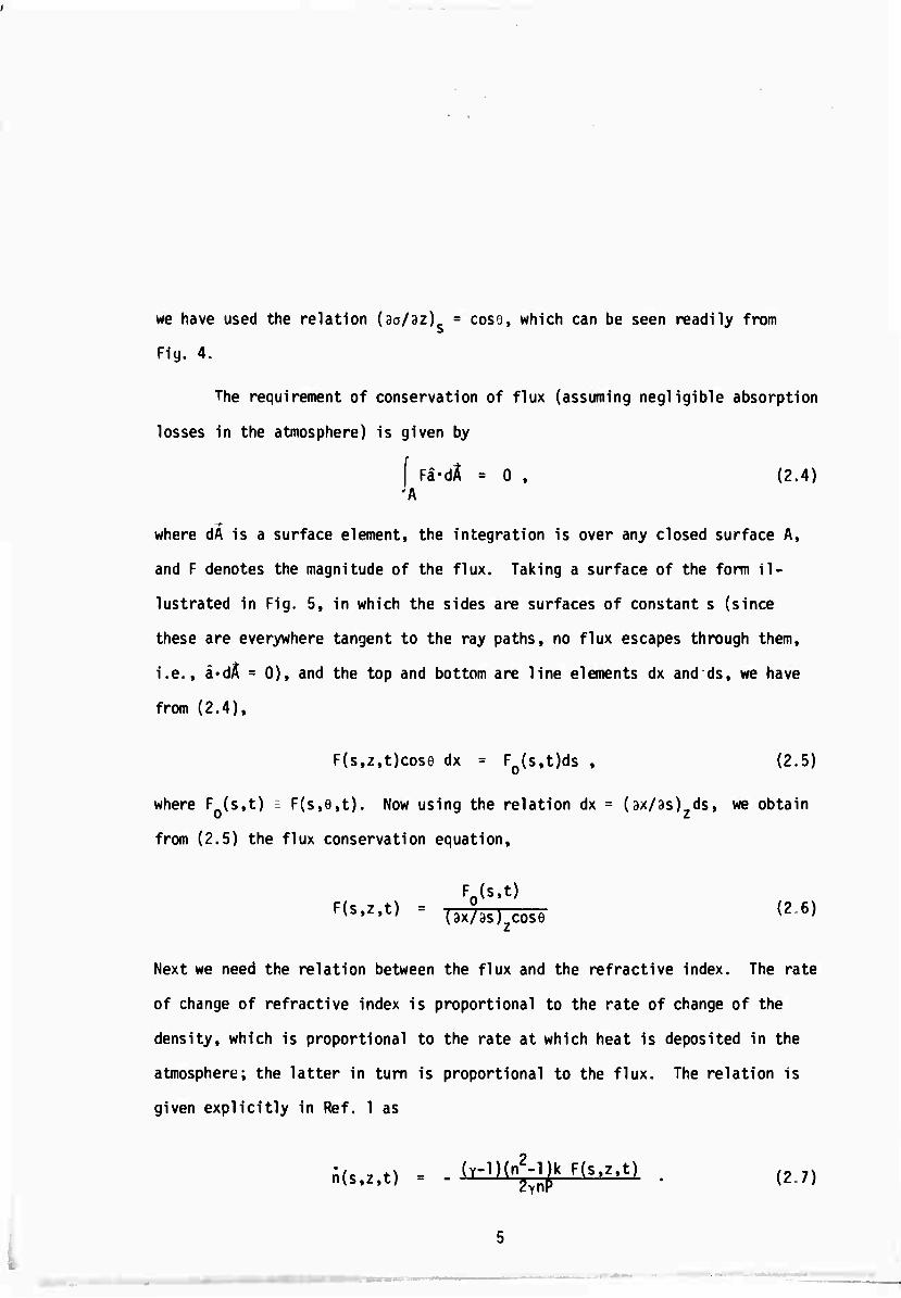
we have used the relation (3a/3z) = coso, which can be seen readily from
Fig. 4.
The requirement of conservation of flux (assuming negligible absorption
losses in the atmosphere) is given by
[ Fa-dX ■ 0 , (2.4) 'A
where dA is a surface element, the integration is over any closed surface A,
and F denotes the magnitude of the flux. Taking a surface of the form Il-
lustrated in Fig. 5, in which the sides are surfaces of constant s (since
these are everywhere tangent to the ray paths, no flux escapes through them,
i.e., a«dÄ = 0), and the top and bottom are line elements dx and ds, we have
from (2.4),
F(s,z,t)cose dx = F0(s,t)ds , (2.5)
where F (s,t) T- F(s,e,t). Now using the relation dx = (ax/as) ds, we obtain
from (2.5) the flux conservation equation,
Fn(s,t)
^'^ = (ax/as)zcos9 (2 6)
Next we need the relation between the flux and the refractive index. The rate
of change of refractive index is proportional to the rate of change of the
density, which is proportional to the rate at which heat is deposited in the
atmosphere; the latter in turn is proportional to the flux. The relation Is
given explicitly in Ref. 1 as
J($.2.t) . ■ <r')^-m F(s.z.t) . (27)
I •
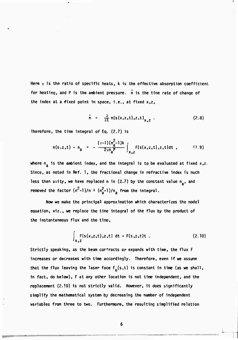
Here y is the ratio of specific heats, k is the effective absorption coefficient
for heating, and P is the ambient pressure, n is the time rate of change of
the index at a fixed point in space, i.e., at fixed x,z.
n = TJI" n[s(x,z,t),z,t]x . (2.8)
Therefore, the time integral of Eq. (2.7) is
(Y-l)(n?-l)k n(s,z,t) - n 77?raf F[s(x,z,t),z,t]dt , (? 9)
x,z
where n is the ambient index, and the integral is to be evaluated at fixed x,z
Since, as noted in Ref. 1, the fractional change in refractive index is much
less than unity, we have replaced n in (2.7) by the constant value n , and a 2 9
removed the factor (n -l)/n = (nf-lVn, from the integral. a a
Now we make the principal approximation which characterizes the model
equation, viz., we replace the time integral of the flux by the product of
the instantaneous flux and the time.
F[s(x,z,t),z,t] dt - F(s,z,t)t . x,z
(2.10)
Strictly speaking, as the beam contracts or expands with time, the flux F
increases or decreases with time accordingly. Therefore, even if we assume
that the flux leaving the laser face F (s,t) is constant in time (as we shall,
in fact, do below), F at any other location is not time independent, and the
replacement (2.10) is not strictly valid. However, it does significantly
simplify the mathematical system by decreasing the number of independent
variables from three to two. Furthermore, the resulting simplified relation
I
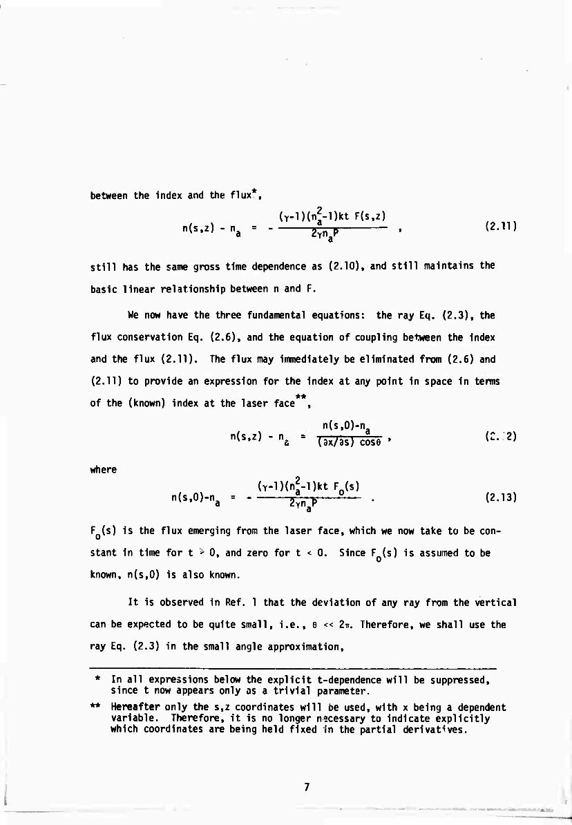
between the index and the flux*,
(Y-l)(n^l)kt F(s,z)
still has the same gross time dependence as (2.10), and still maintains the
basic linear relationship between n and F.
We now have the three fundamental equations: the ray Eq. (2.3), the
flux conservation Eq. (2.6), and the equation of coupling between the index
and the flux (2.11). The flux may immediately be eliminated from (2.6) and
(2.11) to provide an expression for the index at any point in space in terms
of the (known) index at the laser face ,
n(s,0)-na n(s»z) " nS
= (ax/as) cose ' (:- 2)
where
(Y-lHnf-Dkt Fn(s) n<s'0>-na = 50 • <2-13)
F (s) is the flux emerging from the laser face, which we now take to be con-
stant in time for t > 0, and zero for t < 0. Since F (s) is assumed to be
known, n(s,0) is also known.
It is observed in Ref. 1 that the deviation of any ray from the vertical
can be expected to be quite small, i.e., e << 2ir. Therefore, we shall use the
ray Eq. (2.3) in the small angle approximation,
* In all expressions below the explicit t-dependence will be suppressed, since t now appears only as a trivial parameter.
** Hereafter only the s,z coordinates will be used, with x being a dependent variable. Therefore, it is no longer necessary to indicate explicitly which coordinates are being held fixed in the partial derivatives.

Since the variation in index is very small compared to n itself, the term
e9n/9z is of second order in small quantities, and we drop it. Similarly,
because of the small variation in index, we replace the n in nae/az by n .
Finally, noting that in the small angle approximation e is given by
0 ■ 3x/3z, we have
,2 ^ n -n dX 3 X - JJ n \ - 3 a 9S 7? 3s n. 3s n. 3Z 1 a' a
(2.15)
We now define the dimensionless and positive function
n -n(s,0) f(s) £ -ä- , (2.16)
a
so that from (?.12) we have (e << 1)
n. 3X/3S • a
(2.17)
and from (2.13) we have
(Y-l)(nf-l)ktF0(s) f(s) - S 5 . (2.18)
Inserting (2.16) into (2.15) we finally obtain the model equation,
lfj--^[i^]- «■")
8
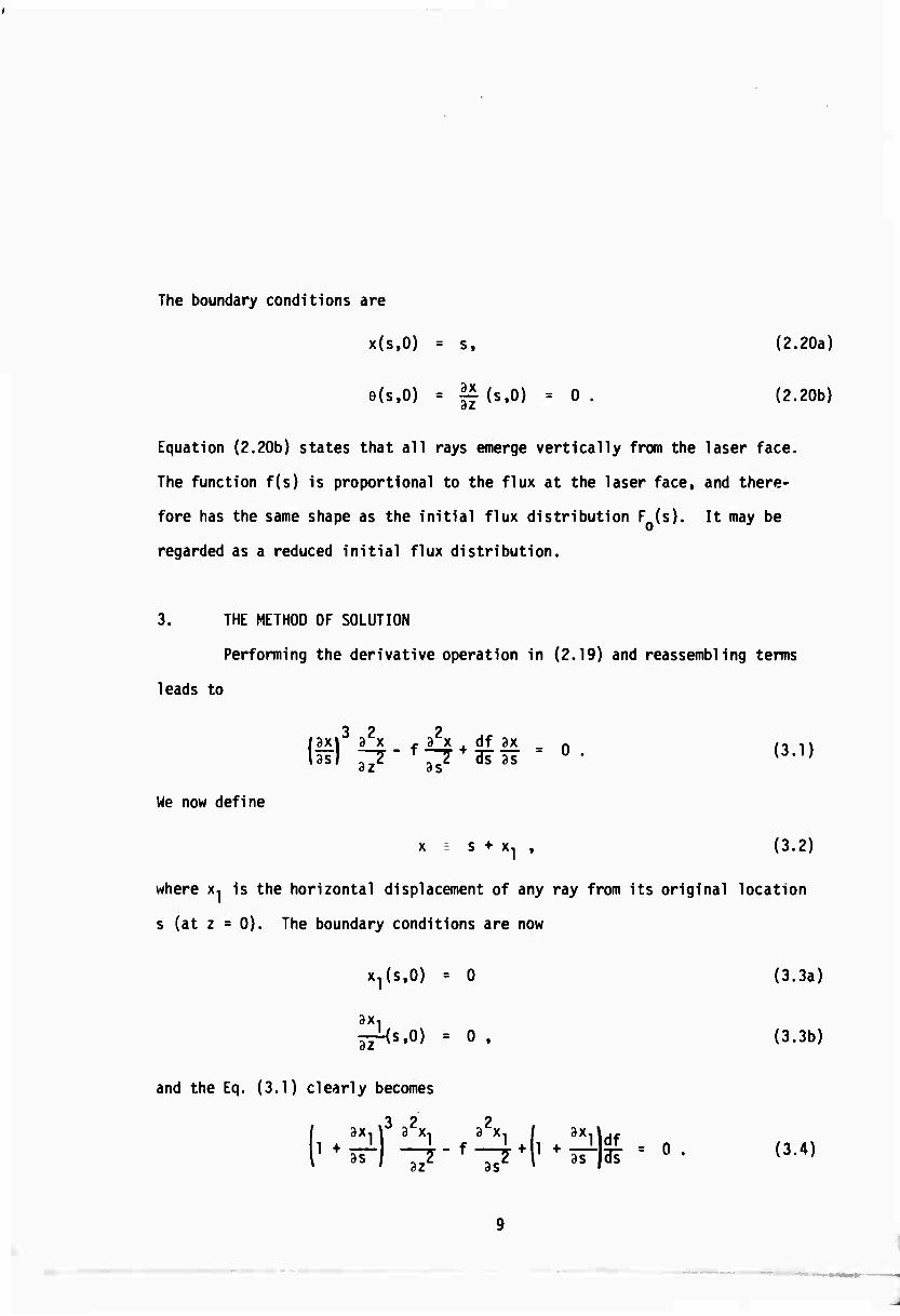
The boundary conditions are
x{s,0) = s, (2.20a)
e(s.O) = |f (s.O) = 0 . (2.20b)
Equation (2.20b) states that all rays emerge vertically from the laser face.
The function f(s) is proportional to the flux at the laser face, and there-
fore has the same shape as the initial flux distribution F (s). It may be
regarded as a reduced initial flux distribution.
3. THE METHOD OF SOLUTION
Performing the derivative operation in (2.19) and reassembling terms
leads to
/ax»3 32x x a2x . df 3x _ n ,- u lisl ^7- f^7 + a?3T - 0 • {3-])
We now define
x = s + x1 , (3.2)
where x, is the horizontal displacement of any ray from its original location
s (at z = 0). The boundary conditions are now
x^s.O) = 0 (3.3a)
3X ä^s.O) = 0 . (3.3b)
and the Eq. (3.1) clearly becomes
f ax,)3 a^, i\ I d*Adf
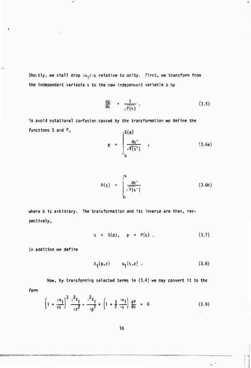
Shortly, we shall drop sx./as relative to unity. First, we transform from
the independent variable s to the new indepenutnt variable p by
d£ ds /f(s)
(3.5)
To avoid notational confusion caused by the transformation we define the
functions S and P, s/_\
ds' P =
.'f(s') (3.6a)
'S
P($) ds'
f(s') (3.6b)
where b is arbitrary. The transformation and its inverse are then, res-
pectively.
s ■ S(p), p - P(s) . (3.7)
In addition we define
X^p.z) x^s.z) (3.8)
Now, by transforming selected terms in (3.4) we may convert it to the
form
3 2 2
as ,2 „2 2 »s ;*Z tp '
df = 0 (3.9)
10
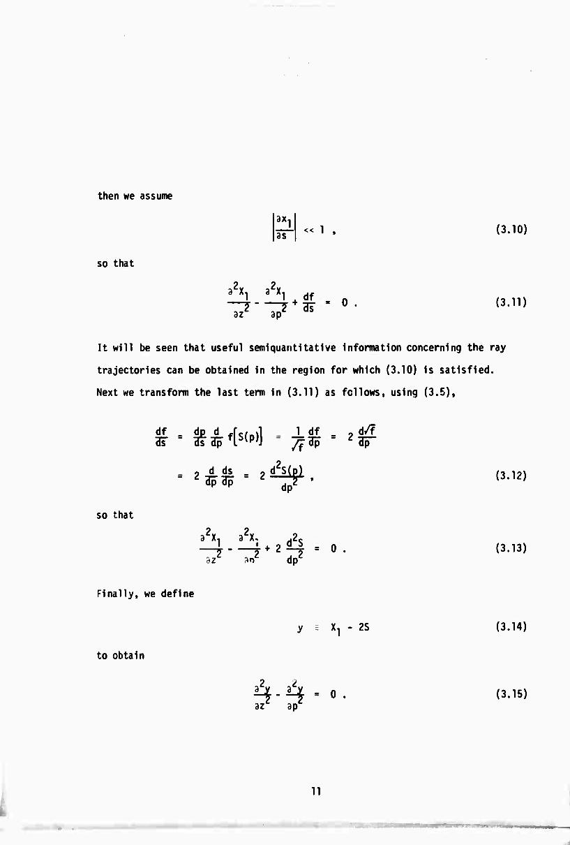
then we assume
8X,
as 1 . (3.10)
so that
3 Xl 3 Xl A df n
az ap (3.11)
It will be seen that useful semiquantitative Information concerning the ray
trajectories can be obtained in the region for which (3.10) is satisfied.
Next we transform the last term in (3.11) as fellows, using (3.5),
df 3?
d/f ■ n'M ■*%■*& = 2 d ds
3p 3p
/f
2d!sipi dp2
(3.12)
so that
I " + o d S _ n T 7 z —? " u
az sn dp (3.13)
Finally, we define
y X, - 2S (3.14)
to obtain
2 2
H-H - 0 • az ap
(3.15)
11
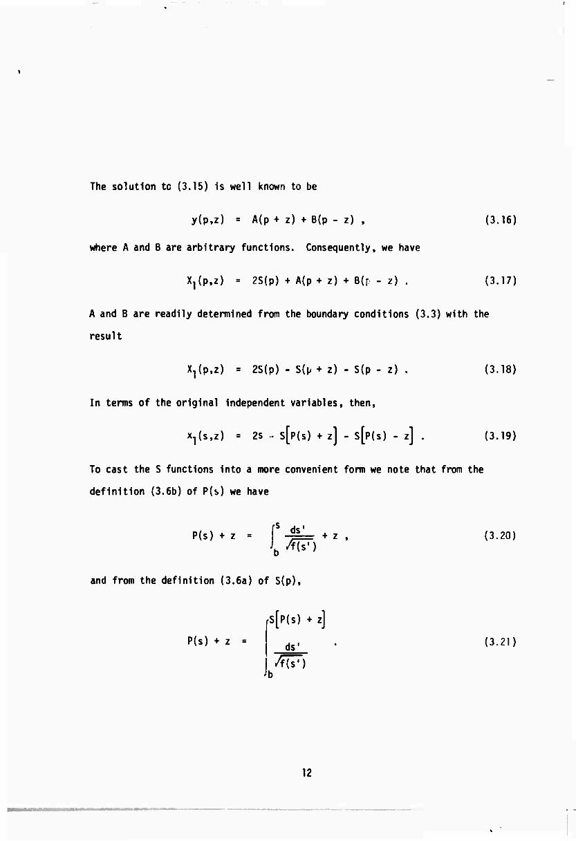
The solution tc (3.15) is well known to be
y(p,z) = A(p + z) + B(p - z) ,
where A and B are arbitrary functions. Consequently, we have
X^p.z) = 2S(p) + A(p + z) + B(r - z)
(3.16)
(3.17)
A and B are readily determined from the boundary conditions (3.3) with the
result
X^p.z) = 2S(p) - S(p+ z) - S(p - z)
In terms of the original independent variables, then.
(3.18)
x^s.z) = 2s • S[P(S) + z] - S[P(S) - z] . (3.19)
To cast the S functions into a more convenient form we note that from the
definition (3.6b) of P(s) we have
P(s) + z ds'
+ z , (3.20)
and from the definition (3.6a) of S(p),
P(s) + z =
fS[p(s) + z]
ds1
W) (3.21)
12

Subtracting (3.?0) from (3.21) yields
fS[P(s)+z]
ds'
/fü7)
Finally, defining
g(s.z) i S[P(s)+zl.
we have the solution
x^s.z)
where g(s,z) is defined by
2s-g(s,z)-g(s,-z) ,
g(s,z)
ds' •
Because of the boundary condition (3.3a) we have
z =
3X
as 1 (s.O) = 0 .
(3.22)
(3.23)
(3.24)
(3.25)
(3.26)
Therefore [see (3.10)1 (3.24) satisfies the model Eq. '3.1) and its boundary
conditions exactly at the z = 0 boundary plane.
13
•

4. SPECIAL CASE
We consider now the special case for which f(s), the reduced initial
flux distribution, is given by
ra2, s ^ 0
f(s) - < . (4.1)
la2 e-2^ . s > 0
This is illustrated in Fig. 2, which shows F (s), to which f(s) is propor- 2
tional. The dimensionless constant a can be expressed in terms of the
relevant physical parameters directly from Eq. (2.18).
The region of negative s represents the interior of the beam, which
in reality of course, will have cylindrical rather than planar symmetry.
In this region the initial flux distribution is uniform, so that the re-
fractive index will initially be constant. According to the ray Eq. (2.1),
the rays deflect towards the direction of the gradient of the index. Here
the gradient vanishes, so we can expect that, at least at first, the rays
will go up vertically, undeflected.
The edge of the beam begins at s = 0, and the intensity falls off
exponentially for s > 0. The heating rate, then, will be greatest along the
positive axis near s = 0. Consequently the index will be srr-dllest near
s = 0, and the gradient will be in the positive direction for s - 0. Thus
all the rays in the beam's edge can be expected to deflect outwards (in
the positive direction). We are interested in seeing when and how the rays
of the interior region (s < 0) first begin to deflect.
14
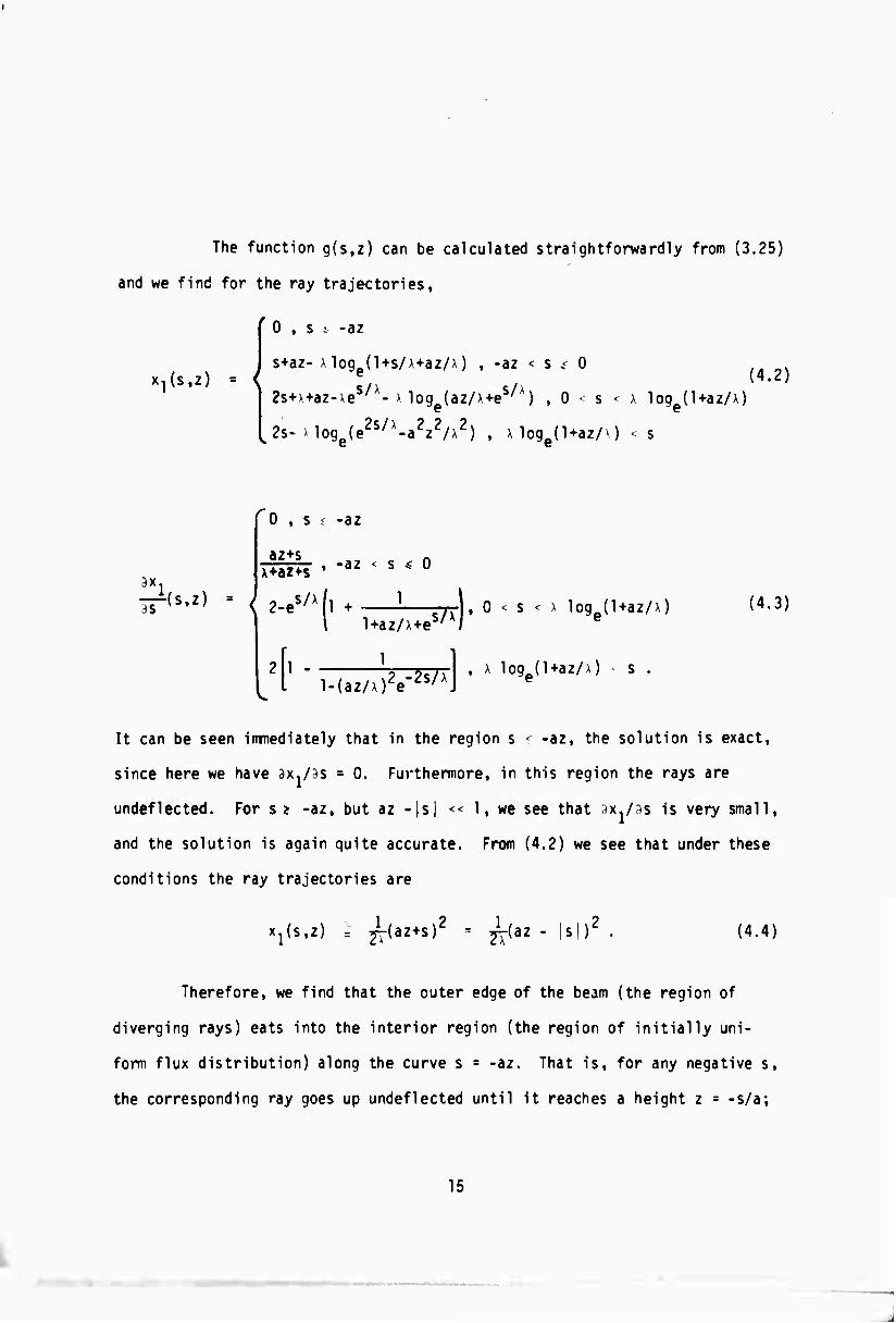
The function g(s,z) can be calculated straightforwardly from (3.25)
and we find for the ray trajectories,
' 0 , s ; -az
^(s.z) = { s+az-) log (1+s/x+az/x) , -az < s „< 0
2s+>+az-Aes/A- > loge(az/>+es/x) ,0s- \ loge(l+az/x)
^2s->loge(e2s/l-a2z2/x2) , x loge(l+az/0 < s
(4.2)
ax. -(s.z)
r 0 , s ; -az
az+s A+az+s , -az < s < 0
2-eS/X(l + ■ TTTI. 0 < s < > logp(Uaz/x) 1 l+az/x+es/x/ e
l-(az/x)2e-2s/xJ , x log0(l+az/0 s
(4.3)
It can be seen immediately that in the region s - -az, the solution is exact,
since here we have ax./ss = 0. Furthermore, in this region the rays are
undeflected. For s* -az, but az -|s| << 1, we see that ^x./ss is very small,
and the solution is again quite accurate. From (4.2) we see that under these
conditions the ray trajectories are
Xjfs.z) = ^-(az+s)2 1
7\ (az - |s|)' (4.4)
Therefore, we find that the outer edge of the beam (the region of
diverging rays) eats into the interior region (the region of initially uni-
form flux distribution) along the curve s = -az. That is, for any negative s,
the corresponding ray goes up undeflected until it reaches a height z = -s/a;
15
-
then it begins to diverge parabolically according to (4.4). This behavior
is illustrated in Fig. 3. It should be noted that the height at which an
interior ray first begins to deflect, z = -s/a, does not depend on the
steepness of the beam's original edge shape. However, once the ray begins
to deflect, it does so more rapidly for a more steeply descending beam edge;
more precisely, we see from (4.4) that the ray displacement Xj is proportional
to 1/A, where A is the scale length for the exponential fall-off of the beam
edge.
The dimensionless constant a is immediately found from (2.18) to be
(4.5) (Y-l)(nJ-l)ktF0
zmfp
Consequently, the height at which an interior ray first begins to deflecv,
z = -s/a, is seen to be inversely proportional to the square root of ktF , o
the amount of heat per unit volume thus far deposited along the ray path.
In addition, we see from the appearance of a in (4.4) that the more heat per
unit volume deposited the more sharply the ray begins to deflect.
Now, If we denote by z0 the target height, and by s the maximum
distance which we can tolerate having the beam's edge eat into its interior,
then from
zo = so/a (4-6)
and (4.5) we can solve imnediately for the maximum tolerable absorption
coefficient k. Taking s0 = R/2, where R is the initial radius of an equivalent
16
cylindrically shaped laser beam, we find
Yn2 PR2
k = a . (4.7)
This expression, except for a factor of two, is the same as that found by
2 Brueckner, et al . It should be noted, however, that qualitatively the
pictures are considerably different. In the latter analysis no specific
consideration is given to the initial shape of the power profile, so that
all rays are treated as equivalent and are implicitly assumed to begin de-
flecting as they leave the laser face; the criterion for determining k is
that the beam may not be permitted to more than double its initial radius
when it reaches target height. By contrast, in the present analysis we
find that for the specific power profile chosen the interior rays do not
deflect at all until they reach a certain height, and the criterion for
determining k is that rays originating in from the edge by more than
half the initial beam radius R may not begin to deflect until target altitude
is reached. Thus, for conditions under which the effective absorption
coefficient for heating is given by Eq. (4.7), the present study would
indicate that the beam power is somewhat less diluted at target altitude
than is indicated by the results in Ref. 2.
17
..
5. SUMMARY
A solution has been found to a model equation, which approximates
the true equation describing the ray trajectories. The approximation occurs
in an expression for the amount of energy per unit volume deposited at any
point along the ray path by the laser beam; it consists of replacing a time
integral over the laser flux by the product of the instantaneous flux and
the time. As a result, the time appears only as a trivial parameter in the
model equation, rather than as an independent variable, as in the true
equation.
The model equation has been solved for the special case of the initial
flux distribution illustrated in Fig. 2; here the geometry is planar and the
flux distribution is uniform in the region representing the interior of the
beam (the negative axis) and descends exponentially in the region representing
the edge of the beam (the positive axis). It is found that the rays of the
interior region behave as illustrated in Fig. 3. That is, they go up un-
detected to a height z = |s/a|, where |s| is the original distance of the
* ** ray in from the edge, and the dimensionless constant a is given by
* Stated conversely, at any height z the exterior region of diverging
rays has eaten its way in from the original edge by a distance
|s| = az.
** In this expression y is the ratio of specific heats, y = Cp/cv, n
is the ambient refractive index, P is the ambient pressure, k is the
effective absorption coefficient for heating of the atmosphere by the
laser light, t is the time, and F is the energy flux leaving the laser
face in the interior, or uniform region.
18
a = M)(na-l)ktF0'
2Yna2P
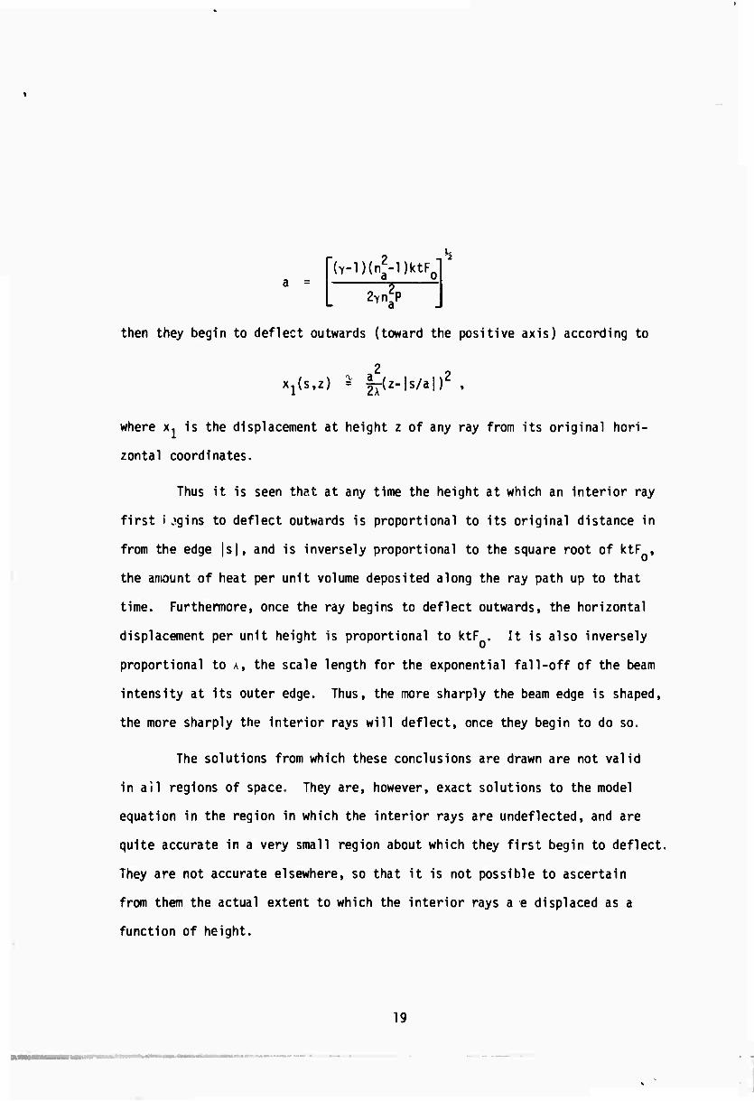
then they begin to deflect outwards (toward the positive axis) according to
XjU.z) ^ |-(z-|s/a|)Z ,
where x, is the displacement at height z of any ray from its original hori-
zontal coordinates.
Thus it is seen that at any time the height at which an interior ray
first i „Mjins to deflect outwards is proportional to its original distance in
from the edge |s|, and is inversely proportional to the square root of ktF ,
the amount of heat per unit volume deposited along the ray path up to that
time. Furthermore, once the ray begins to deflect outwards, the horizontal
displacement per unit height is proportional to ktF . It is also inversely
proportional to A, the scale length for the exponential fall-off of the beam
intensity at its outer edge. Thus, the more sharply the beam edge is shaped,
the more sharply the interior rays will deflect, once they begin to do so.
The solutions from which these conclusions are drawn are not valid
in ail regions of space. They are, however, exact solutions to the model
equation in the region in which the interior rays are undeflected, and are
quite accurate in a very small region about which they first begin to deflect.
They are not accurate elsewhere, so that it is not possible to ascertain
from them the actual extent to which the interior rays a e displaced as a
function of height.
19

Fig. 1. Radial distribution of flux F (r) at the laser face for which
the gradient of the refractive index points inward for r < R
and outward for r > R. In this case the rays in the outer
region r > R will diverge, but the rays in the inner region
r < R will converge initially.
F0(.)
Fig. 2. Uniform distribution of flux F (s) emanating from a semi-
infinite laser face (s < 0), with an exponential fall-off at the edge. The rays originating in the uniform region
along the negative s-axis are initially undeflected.
Those originating along the positive s-axis are immediately
deflected to the right.
20
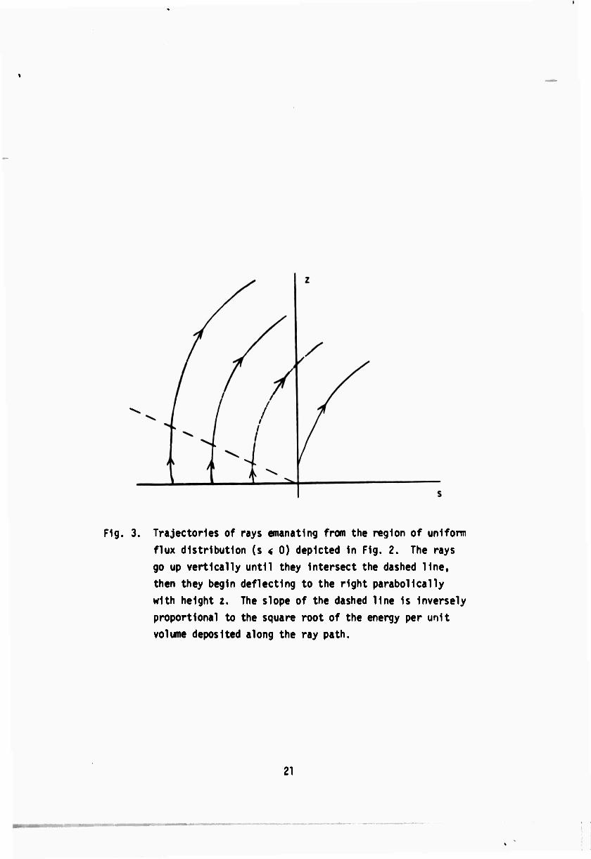
Fig. 3. Trajectories of rays emanating from the region of uniform
flux distribution (s < 0) depicted In Fig. 2. The rays
go up vertically until they Intersect the dashed line,
then they begin deflecting to the right parabolically
with height z. The slope of the dashed line Is Inversely
proportional to the square root of the energy per unit
volume deposited along the ray path.
21

z
/ dx / /
dz
i
Vdc
1 i t
1 1 i
s
Fig. 4. Typical ray trajectory, showing the angle e and the incremental
quantities dx, dz, and do at fixed s.
ds
Fig. 5. Neighboring ray trajectories separated by an infinitesimal
radial distance ds at the laser face, and by a corresponding
radial distance dx at an arbitrary height z.
22
■ •
REFERENCES
1. S. Altshuler, D. Arnush, L.M. Frantz, T.D. Holstein, "High Intensity
Laser Propagation in the Atmosphere(U)" Secret Semiannual Report
05691-6006-R3-00, dated 1 March 1968.
2. Brueckner, et al., JMDR 2, 11 (1964).
23
Unclassified
^.nfitycimtfictuon
DOCUMENT CONTROL DATA -R&D l$9tmUf rlmiHllrmll*) »t till», k»4r ol »titf f I mn4 Indttlnf mmtlmtli) wv«> km twWgg »h»m Hi» »rmtmll rmatt I» rlfltlmd)
■ oniciN* riNO «C TiviTT (C«q»*M(* avrti*r>
Office of Naval Research (ONR) Department of the Navy Washington, D.C. 20360
M. *C»e«T «CCUNITT CLAltlPICATlO»
Dpclaaaificd I», an our
i niponr TITLK
HIGH INTENSITY LASER PROPAGATION IN THE ATMOSPHERE
« 0((C«I»TIVINOT|| (TVp* ol rupori and Inc/u*«*» dmimt)
Semiannual Report, 1 July 1968 - 30 December 1968. t «uTHOnifl (fitu n»mm, middlm inlllml. (a«I nan«;
L. M. Frantz
a nE»oft r o » ft
.lanuary 1968
im. TOTAk NO O» »AOtf
27 7*. NO OF MIFt
2 1. CONTMACT OH CM/kNT NO
N00014-66-C0022 6. PHOJCCT NO
ARPA Order 306 c.
•Ill
05691-6011-R0-00
o TMCR ncnonr NOISI fAnr oihtr ninnkari tf>ar mar »• mttlmtmd thli npmtt)
tO Oil niBUTlON STATCMCNT
This document has been approved for public release and sale; Its distribution is unlimited.
ii njnri.«MeNT»ny NOTE» il troNtoniNC MIUI nr ACTIVITY
ARPA, the Office of Naval Research and the Department of Defense
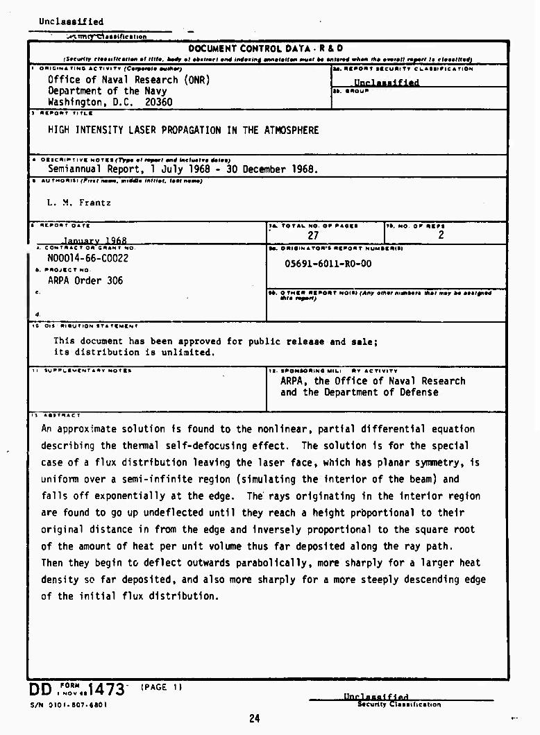
An approximate solution is found to the nonlinear, partial differential equation
describing the thermal self-defocusing effect. The solution is for the special
case of a flux distribution leaving the laser face, which has planar symmetry, is
uniform over a semi-infinite region (simulating the interior of the beam) and
falls off exponentially at the edge. The rays originating in the interior region
are found to go up undeflected until they reach a height proportional to their
original distance in from the edge and inversely proportional to the square root
of the amount of heat per unit volume thus far deposited along the ray path.
Then they begin to deflect outwards parabolically, more sharply for a larger heat
density so far deposited, and also more sharply for a more steeply descending edge
of the initial flux distribution.
DDl,r,..1473 <PAGE n
S/N 3101.807.6801 Security Clatufication
24
UnclaiilfUd ■•curlty ClMatrteaitM
LINK *
• Ot« mr noi.«
Self defocusing
Thermal defocusing
Laser beam defocusing
Beam dynamics
Intense laser beams
Nonllrear propagation effect
Shaped power profile
Initial beam convergence
DD :Z?»U73 BACK) (PAGE* 2!
Unclassified
25 Security CUitificatien