tm-series - katedra telekomunikacji aghkt.agh.edu.pl/~lason/01_td/05_td-tm3000_y.pdf · in no event...
TRANSCRIPT
TM-Series Technical Description TM-3000 chassis Rev Y, 2009-12-21
IN COMMERCIAL CONFIDENCE TECHNICAL DESCRIPTION TM-3000
Date: Doc. number: Rev: Page
© Transmode 2009-12-21 TD-TM3000 Y 2 (46)
1 GENERAL
The specifications and information within this manual are subject to change without further notice. All statements, information and recommendations are believed to be accurate but are presented without warranty of any kind. Users must take full responsibility for their application of any products.
In no event shall Transmode Systems AB be liable for any indirect, special, consequential or incidental damages, including, without limitation, lost profits or loss or damage to data arising from the use or inability to use this manual, even if Transmode or its suppliers have been advised of the possibility of such damages.
1.1 In commercial confidence
The manual is provided in commercial confidence and shall be treated as such.
1.2 Document Revision History
Revision Date Description of changes A 2002-05-03 First released version B 2002-09-02 Added information about temperature alarms. C 2002-12-12 Inclusion of TM-3000 R2 revision D 2003-03-18 Enhanced information with pictures.
Fiber management guide addition. E 2004-03-21 Basic NE Equipment addition. Added information in
Technical Data. Added information on restrictions. F 2004-10-02 Added technical info in chapter 6. Product identification
chapter added G 2005-06-30 Transition to new Transmode format. No content change H 2005-10-31 Introduction of external AC/DC converter I 2005-12-20 Introduction of new ordering number for more detailed
configurations J 2006-04-20 Introduction of power and fiber inlet openings (R1C) K 2006-06-20 Added label information.
Added information on air filter maintenance L 2006-11-20 Corrected and updated content in chapter 2.1
Corrected max power consumption values in Table 7 M 2007-04-01 Update of R-state due to NEBS support. N 2007-06-28 Clarification of height in U (Table 7) O 2007-12-21 Updated with new mechanical shelf P 2008-01-18 Added information on new article codes
Added information on NE size supported by different CU versions (chapter 2.1)
Q 2008-03-11 Updated 40ch example configuration in chapter 7.6 R 2008-05-28 Change of logotype. Added information on airflow in chapter
2.3.1 S 2008-11-28 Updated power consumption, content list. General
enhancements T 2009-01-16 Added information about R4 version U 2009-01-30 Addition of chapter 3.1
Enhanced technical information in chapter 6 Corrected information in chapter 4, plus addition of 80ch configuration.
V 2009-02-10 Addition of chapter 4.5 W 2009-06-15 Updated tables in chapter 3.1 to reflect release 13.0 content.
Introduction of new DC/DC-module X 2009-07-10 Addition of max inrush current values in Table 7
Release 14.0 update; VOA/2P supported in Table 3
Transmode Systems AB © 2009 Transmode Systems AB Box 42114 All rights reserved. No part of this document SE-126 14 Stockholm may be reproduced without written Home page: www.transmode.com SWEDEN permission of the copyright holder

IN COMMERCIAL CONFIDENCE TECHNICAL DESCRIPTION TM-3000
Date: Doc. number: Rev: Page
© Transmode 2009-12-21 TD-TM3000 Y 3 (46)
Revision Date Description of changes Y 2009-12-21 MDU-8 units incorrectly stated not to be supported IN
TM-301. Corrected Table 3
Table of content 1 General...............................................................................................................2 1.1 In commercial confidence ...............................................................................................2 1.2 Document Revision History.............................................................................................2 2 Functional Description........................................................................................4 2.1 Introduction .....................................................................................................................4 2.2 Basic configurations........................................................................................................5 2.3 TM-3000 chassis.............................................................................................................6 2.3.1 Fan units .........................................................................................................................7 2.3.2 Air filter............................................................................................................................9 2.3.3 Primary power alternatives..............................................................................................9 2.3.4 External interfaces ........................................................................................................11 2.3.5 Card Cage.....................................................................................................................12 2.3.6 Chassis identity.............................................................................................................13 2.3.7 Sys mode......................................................................................................................13 2.3.8 Fiber management........................................................................................................14 3 Configuration guidelines...................................................................................16 3.1 Plug-in unit data & chassis compatibility .......................................................................18 4 Revision updates..............................................................................................21 4.1 R1C updates .................................................................................................................21 4.2 R2A update ...................................................................................................................22 4.3 R3A updates .................................................................................................................22 4.4 R4 updates....................................................................................................................24 4.5 Board Extraction tool.....................................................................................................25 5 Labels ...............................................................................................................26 6 Technical data ..................................................................................................28 6.1 Mechanical drawing ......................................................................................................29 6.2 Revision data ................................................................................................................30 6.3 Ordering data ................................................................................................................31 6.3.1 Spare parts ...................................................................................................................32 7 APPENDIX .......................................................................................................33 7.1 TM-3000 Configurations................................................................................................33 7.2 32ch 100GHz 10G System, example 1.........................................................................34 7.3 32ch 100GHz 10G System, example 2.........................................................................36 7.4 32ch 100GHz 2.5G System example............................................................................38 7.5 32ch 100GHz 2.5G System example without VOA’s ....................................................40 7.6 40ch 50GHz 10G System .............................................................................................41 7.7 80ch 50GHz 10G System .............................................................................................43
Transmode Systems AB © 2009 Transmode Systems AB Box 42114 All rights reserved. No part of this document SE-126 14 Stockholm may be reproduced without written Home page: www.transmode.com SWEDEN permission of the copyright holder
IN COMMERCIAL CONFIDENCE TECHNICAL DESCRIPTION TM-3000
Date: Doc. number: Rev: Page
© Transmode 2009-12-21 TD-TM3000 Y 4 (46)
2 FUNCTIONAL DESCRIPTION
2.1 Introduction
The TM-3000 chassis is the largest chassis alternative in the TM-Series. The TM-3000 chassis has a generic backplane giving a high level of flexibility. As an example, all slots can be used for full-height plug-in units (Transponders, MDU’s, amplifiers etc) or for a mix of full-height and half-height plug-in units.
The generic backplane enables a TM-3000 chassis to be configured as a multi-purpose Network Element (NE). As an example, a TM-3000 chassis can contain a DWDM Terminal Multiplexer, a DWDM line amplifier and a CWDM add/drop node. The node manager will support any combination of plug-in units and NE types.
A Control Unit (CU) is always placed in the first slot. The CU gives an aggregated management view of the chassis. Multiple TM-3000 chassis can be connected in a master-slave configuration to provide a larger Network Element (NE).
The R3-version (and later) of the TM-3000 chassis has a flexible mechanical solution for the shelf that supports passive, half-height units. The standard length is 1 slot. Delivered with every chassis there will be a kit enabling the shelf to be extended to 2, 3, 4 or 5 slot lengths. So each chassis can easily be configured at the site.
The selection of primary power, mounting alternative and CU type is straightforward. The selection of shelf length for passive units will require some analysis since it depends on what type of Network Element (NE) that is to be created and what units that are to be mounted into the card cage. See chapter 7 for more details.
Multiple chassis can be connected in a master-slave configuration to create larger NE’s. For memory and capacity reasons a CU-SFP must be used as a “master CU” when the number of connected chassis exceeds 2. The slave chassis can use a Control Unit of old type (CU).
See “Dimensioning Guidelines” within the System Manual for more details on restrictions.
For details on installation procedure, see “TM-3000 Installation Guide” within the Installation & Commissioning volume of the TM-Series System manual.
Transmode Systems AB © 2009 Transmode Systems AB Box 42114 All rights reserved. No part of this document SE-126 14 Stockholm may be reproduced without written Home page: www.transmode.com SWEDEN permission of the copyright holder
IN COMMERCIAL CONFIDENCE TECHNICAL DESCRIPTION TM-3000
Date: Doc. number: Rev: Page
© Transmode 2009-12-21 TD-TM3000 Y 5 (46)
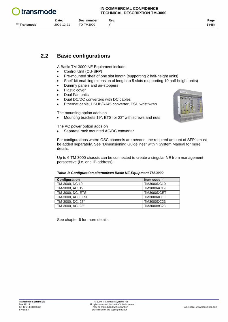
2.2 Basic configurations
A Basic TM-3000 NE Equipment include • Control Unit (CU-SFP) • Pre-mounted shelf of one slot length (supporting 2 half-height units) • Shelf-kit enabling extension of length to 5 slots (supporting 10 half-height units) • Dummy panels and air-stoppers • Plastic cover • Dual Fan units • Dual DC/DC converters with DC cables • Ethernet cable, DSUB/RJ45 converter, ESD wrist wrap The mounting option adds on • Mounting brackets 19”, ETSI or 23” with screws and nuts The AC power option adds on • Separate rack mounted AC/DC converter
For configurations where OSC channels are needed, the required amount of SFP’s must be added separately. See “Dimensioning Guidelines” within System Manual for more details.
Up to 6 TM-3000 chassis can be connected to create a singular NE from management perspective (i.e. one IP-address). Table 1: Configuration alternatives Basic NE-Equipment TM-3000
Configuration Item code 1) TM-3000, DC 19 TM3000DC19 TM-3000, AC, 19 TM3000AC19 TM-3000, DC, ETSI TM3000DCET TM-3000, AC, ETSI TM3000ACET TM-3000, DC, 23” TM3000DC23 TM-3000, AC, 23” TM3000AC23
See chapter 6 for more details.
Transmode Systems AB © 2009 Transmode Systems AB Box 42114 All rights reserved. No part of this document SE-126 14 Stockholm may be reproduced without written Home page: www.transmode.com SWEDEN permission of the copyright holder

IN COMMERCIAL CONFIDENCE TECHNICAL DESCRIPTION TM-3000
Date: Doc. number: Rev: Page
© Transmode 2009-12-21 TD-TM3000 Y 6 (46)
2.3 TM-3000 chassis
The TM-3000 chassis can be divided into three parts:
• Fan area • Card cage • Power and external interfaces
Figure 1: The three main parts of a TM-3000 chassis
The Fan and Power and external interface areas are covered with plates that are screwed to the mechanics via thumbscrews that are easy to loosen. The cover plates can be flipped open via the hinges for easy access to e.g. fan units.
Different mounting brackets are used when mounting the TM-3000 into an ETSI, 19” or a 23” rack.
A number of TM-3000 chassis can be connected to form a one-entity NE from management perspective. See “Dimensioning Guidelines” within the System Manual for restrictions on number of chassis and other restrictions.
Transmode Systems AB © 2009 Transmode Systems AB Box 42114 All rights reserved. No part of this document SE-126 14 Stockholm may be reproduced without written Home page: www.transmode.com SWEDEN permission of the copyright holder
IN COMMERCIAL CONFIDENCE TECHNICAL DESCRIPTION TM-3000
Date: Doc. number: Rev: Page
© Transmode 2009-12-21 TD-TM3000 Y 7 (46)
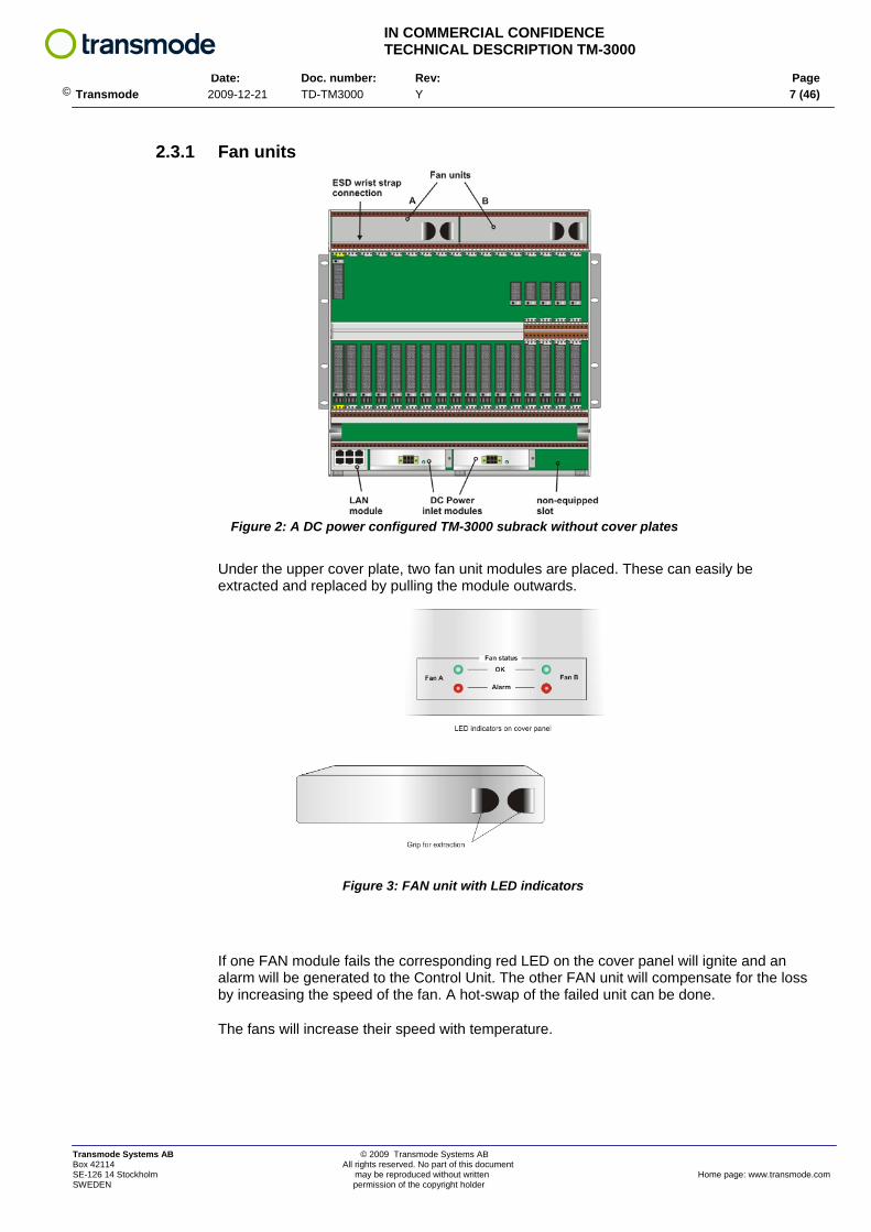
2.3.1 Fan units
Figure 2: A DC power configured TM-3000 subrack without cover plates
Under the upper cover plate, two fan unit modules are placed. These can easily be extracted and replaced by pulling the module outwards.
Figure 3: FAN unit with LED indicators
If one FAN module fails the corresponding red LED on the cover panel will ignite and an alarm will be generated to the Control Unit. The other FAN unit will compensate for the loss by increasing the speed of the fan. A hot-swap of the failed unit can be done.
The fans will increase their speed with temperature.
Transmode Systems AB © 2009 Transmode Systems AB Box 42114 All rights reserved. No part of this document SE-126 14 Stockholm may be reproduced without written Home page: www.transmode.com SWEDEN permission of the copyright holder
IN COMMERCIAL CONFIDENCE TECHNICAL DESCRIPTION TM-3000
Date: Doc. number: Rev: Page
© Transmode 2009-12-21 TD-TM3000 Y 8 (46)
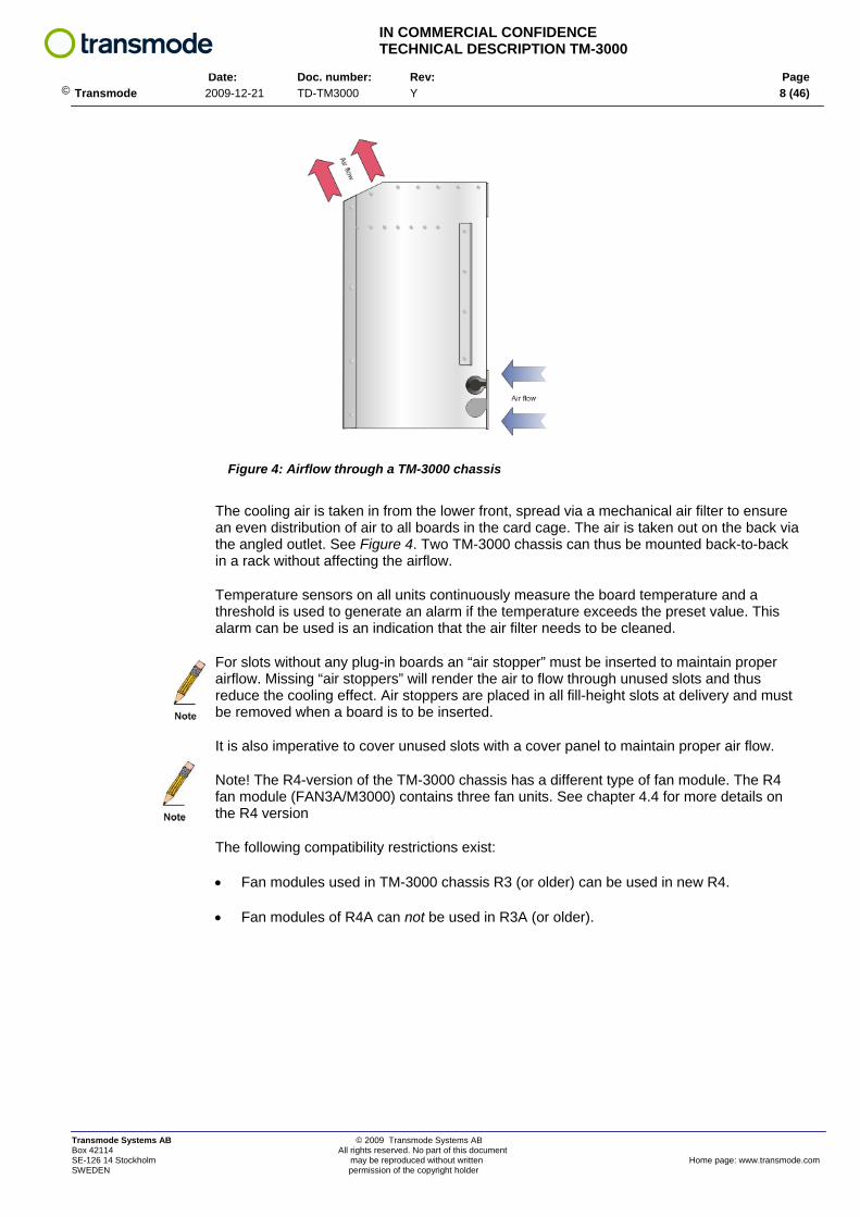
Figure 4: Airflow through a TM-3000 chassis
The cooling air is taken in from the lower front, spread via a mechanical air filter to ensure an even distribution of air to all boards in the card cage. The air is taken out on the back via the angled outlet. See Figure 4. Two TM-3000 chassis can thus be mounted back-to-back in a rack without affecting the airflow.
Temperature sensors on all units continuously measure the board temperature and a threshold is used to generate an alarm if the temperature exceeds the preset value. This alarm can be used is an indication that the air filter needs to be cleaned.
For slots without any plug-in boards an “air stopper” must be inserted to maintain proper airflow. Missing “air stoppers” will render the air to flow through unused slots and thus reduce the cooling effect. Air stoppers are placed in all fill-height slots at delivery and must be removed when a board is to be inserted.
It is also imperative to cover unused slots with a cover panel to maintain proper air flow.
Note! The R4-version of the TM-3000 chassis has a different type of fan module. The R4 fan module (FAN3A/M3000) contains three fan units. See chapter 4.4 for more details on the R4 version
The following compatibility restrictions exist:
• Fan modules used in TM-3000 chassis R3 (or older) can be used in new R4.
• Fan modules of R4A can not be used in R3A (or older).
Transmode Systems AB © 2009 Transmode Systems AB Box 42114 All rights reserved. No part of this document SE-126 14 Stockholm may be reproduced without written Home page: www.transmode.com SWEDEN permission of the copyright holder

IN COMMERCIAL CONFIDENCE TECHNICAL DESCRIPTION TM-3000
Date: Doc. number: Rev: Page
© Transmode 2009-12-21 TD-TM3000 Y 9 (46)
2.3.2 Air filter
An air filter is placed under the card cage. This filter should be extracted and cleaned every second year under normal conditions. See System Manual “Installation & Commissioning” for more details.
Note! The R4-version of the TM-3000 chassis has a different type of air filter solution. The R4 air filters cover half the card cage. R3 (and earlier) filters are a singular solution expanding over the whole card cage. With the R4 solution it will no longer be required to remove the lower fiber management mechanics when extracting the air filters. See chapter 4.4 for more details on the R4 version.
2.3.3 Primary power alternatives
2.3.3.1 DC-power
For direct -48V DC powering, two DC power inlet modules are inserted in the two mid slots. The two modules are used to enable A & B power configurations. 2-wire and 3-wire configurations are possible.
Figure 5: DC power configuration
The DC power inlet module (see Figure 5) has a green LED indicator to indicate a functioning unit. The LED’s can be seen also when the cover panel is in place. Upon failure, the green LED will be turned off and an alarm will be generated to the management system. A hot-swap replacement of the failed module can be done. The right module variant will eventually be phased out and be replaced by the left variant.
A red LED to indicate polarity error, i.e. the – 48 voltage has been wrongly connected. This is only a visual indication and will not generate any alarm to the management system. In release 13.0 (June 2009) an updated version of the DC/DC module is introduced. The R-stage is stepped from R1E to R1F. The R1F version has a higher efficiency (i.e. lower power consumption), a DC soft start functionality to avoid rush currents and start-up and improved current spike tolerance. The R1F will be fully introduced during 2009.
Transmode Systems AB © 2009 Transmode Systems AB Box 42114 All rights reserved. No part of this document SE-126 14 Stockholm may be reproduced without written Home page: www.transmode.com SWEDEN permission of the copyright holder
IN COMMERCIAL CONFIDENCE TECHNICAL DESCRIPTION TM-3000
Date: Doc. number: Rev: Page
© Transmode 2009-12-21 TD-TM3000 Y 10 (46)
2.3.3.2 AC-power
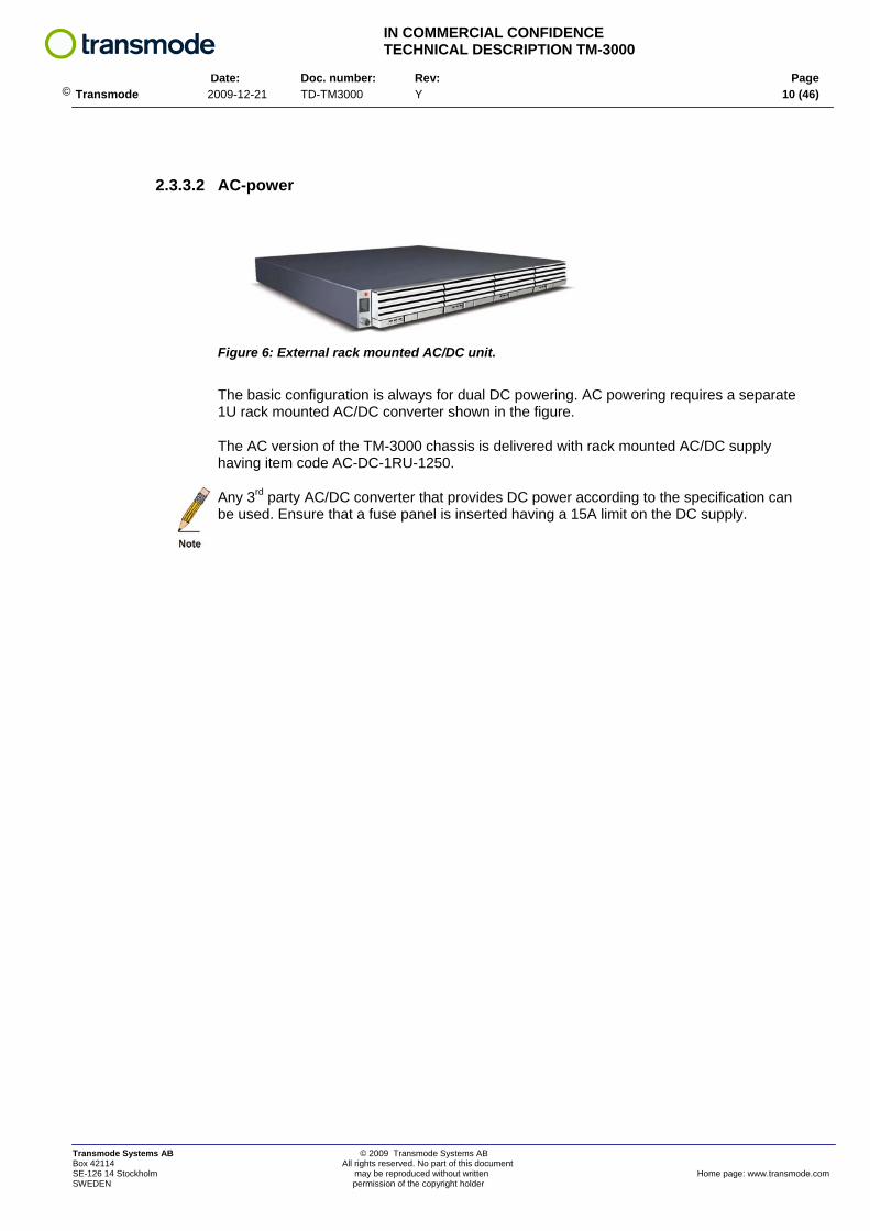
Figure 6: External rack mounted AC/DC unit.
The basic configuration is always for dual DC powering. AC powering requires a separate 1U rack mounted AC/DC converter shown in the figure.
The AC version of the TM-3000 chassis is delivered with rack mounted AC/DC supply having item code AC-DC-1RU-1250.
Any 3rd party AC/DC converter that provides DC power according to the specification can be used. Ensure that a fuse panel is inserted having a 15A limit on the DC supply.
Transmode Systems AB © 2009 Transmode Systems AB Box 42114 All rights reserved. No part of this document SE-126 14 Stockholm may be reproduced without written Home page: www.transmode.com SWEDEN permission of the copyright holder
IN COMMERCIAL CONFIDENCE TECHNICAL DESCRIPTION TM-3000
Date: Doc. number: Rev: Page
© Transmode 2009-12-21 TD-TM3000 Y 11 (46)
2.3.4 External interfaces
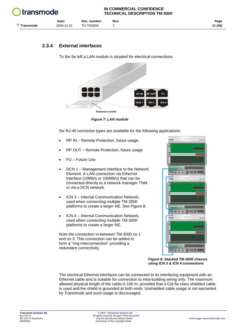
To the far left a LAN module is situated for electrical connections.
Figure 7: LAN module
Six RJ-45 connector types are available for the following applications:
• RP IN – Remote Protection, future usage.
• RP OUT – Remote Protection, future usage
• FU – Future Use
• DCN 1 – Management interface to the Network Element. A LAN-connection via Ethernet interface (10Mb/s or 100Mb/s) that can be connected directly to a network manager TNM or via a DCN network.
• ICN 3 – Internal Communication Network, used when connecting multiple TM-3000 platforms to create a larger NE. See Figure 8.
• ICN 4 – Internal Communication Network, used when connecting multiple TM-3000 platforms to create a larger NE.
Note the connection in-between TM-3000 no 1 and no 3. This connection can be added to form a “ring interconnection” providing a redundant connectivity.
Figure 8: Stacked TM-3000 chassis using ICN 3 & ICN 4 connections
The electrical Ethernet interfaces can be connected to its interfacing equipment with an Ethernet cable and is suitable for connection to intra-building wiring only. The maximum allowed physical length of the cable is 100 m, provided that a Cat 5e class shielded cable is used and the shield is grounded at both ends. Unshielded cable usage is not warranted by Transmode and such usage is discouraged.
Transmode Systems AB © 2009 Transmode Systems AB Box 42114 All rights reserved. No part of this document SE-126 14 Stockholm may be reproduced without written Home page: www.transmode.com SWEDEN permission of the copyright holder

IN COMMERCIAL CONFIDENCE TECHNICAL DESCRIPTION TM-3000
Date: Doc. number: Rev: Page
© Transmode 2009-12-21 TD-TM3000 Y 12 (46)
2.3.5 Card Cage
Figure 9: The Card cage area
The card cage has 17 slots for plug-in units. The far left slot is dedicated for a Control Unit. The card guide is coded via a yellow color.
The following eleven slots (slot 2 – 12) can be equipped with any type of full-height traffic units due to the generic back plane. The last five slots (13 – 17) can either be used for full-height or half-height units. The half-height units require a small shelf to support the smaller board sizes. This is a modular shelf and the number of half-height units is given by the length of the shelf. In Figure 9 a shelf with a length allowing for four upper and four lower half-height slots are shown. Additional slots (18-22) are thus available when using the half-height configuration.
With the R3 version (and later) the shelf length can be changed from 1 to 5 via access within the card cage. A screw must be accessed from the outside to remove the last shelf module if all slots are to be used for full-height units.
It is thus possible to customize a TM-3000 chassis to a configuration between 17 full-height units, or 12 full-height and 10 half-height units. Note that the total power consumption must not exceed the maximum allowed (600W). See also chapter 3
Full-height units are normally active traffic devices (e.g. Transponder). Half-height units are normally passive optical devices (e.g. add/drop filters).
When a unit is inserted into a card slot, the slot position is detected by the unit and forwarded to the Control Unit. This includes also the passive units.
The slot numbers are indicated just above the card cage area.
The slot for a CU is 20mm x 262mm, Traffic Unit slot is 25mm x 262mm and the passive half-height slots are 25mm x 129mm.
Transmode Systems AB © 2009 Transmode Systems AB Box 42114 All rights reserved. No part of this document SE-126 14 Stockholm may be reproduced without written Home page: www.transmode.com SWEDEN permission of the copyright holder

IN COMMERCIAL CONFIDENCE TECHNICAL DESCRIPTION TM-3000
Date: Doc. number: Rev: Page
© Transmode 2009-12-21 TD-TM3000 Y 13 (46)
2.3.6 Chassis identity
Each chassis within a NE must have a unique ID number. The chassis identity is set by a DIP-switch that is located on the backside of the lid that covers the fan unit area. By releasing the thumbscrews and flipping the cover downwards, the backside of the circuit board with the LED indicators for the fan units is revealed. See Figure 10.
Figure 10: DIP switch for subrack ID
The procedure is described in the “Installation & Commissioning” Volume of the System Manual.
2.3.7 Sys mode
The second part of the DIP switch is used to set the NE into a mode where a replacement CU can inherit the previous CU configuration. The procedure is described in the “Installation & Commissioning” Volume of the System Manual.
Transmode Systems AB © 2009 Transmode Systems AB Box 42114 All rights reserved. No part of this document SE-126 14 Stockholm may be reproduced without written Home page: www.transmode.com SWEDEN permission of the copyright holder

IN COMMERCIAL CONFIDENCE TECHNICAL DESCRIPTION TM-3000
Date: Doc. number: Rev: Page
© Transmode 2009-12-21 TD-TM3000 Y 14 (46)
2.3.8 Fiber management
To ease patch cord management, a mechanical guide is placed under the card cage (see Figure 11). This guide will ensure that the patch cords are evenly distributed into the fiber management area.
The R4 revision of the TM-3000 chassis has mechanical guides also on the upper part of the card cage.
See chapter 4.4 for more details on the R4 version.
Figure 11: Fiber management
Fiber management mechanics
Figure 12: TM-3000 R4 version
Additional fiber management mechanics are provided on the 40ch MDU’s (MDU40/50G-EVEN and MDU40/50G-ODD) of revision C and later. A separate cover plate can be added to the right of these MDU units to further support fiber management to/from the 40ch MDU units. See Technical Description for these MDU units for more details.
Transmode Systems AB © 2009 Transmode Systems AB Box 42114 All rights reserved. No part of this document SE-126 14 Stockholm may be reproduced without written Home page: www.transmode.com SWEDEN permission of the copyright holder

IN COMMERCIAL CONFIDENCE TECHNICAL DESCRIPTION TM-3000
Date: Doc. number: Rev: Page
© Transmode 2009-12-21 TD-TM3000 Y 15 (46)
Figure 13: Example node with 40ch MDU
The figure shows an example node with a 40ch MDU with the separate fiber management panel. The MDU40 has 24 internal line connections and the remaining 16 are connected to a second chassis. The card cage is covered with the plastic cover (described in chapter 4.3)
Transmode Systems AB © 2009 Transmode Systems AB Box 42114 All rights reserved. No part of this document SE-126 14 Stockholm may be reproduced without written Home page: www.transmode.com SWEDEN permission of the copyright holder

IN COMMERCIAL CONFIDENCE TECHNICAL DESCRIPTION TM-3000
Date: Doc. number: Rev: Page
© Transmode 2009-12-21 TD-TM3000 Y 16 (46)
3 CONFIGURATION GUIDELINES
The maximum number of traffic units that can be inserted into the card cage is limited by the total power consumption that can be handled within the card cage.
The max power consumption of a fully equipped TM-3000 is 600W in DC configuration, including fans, primary power etc. With a fuse limit of 15A and worst case primary power supply voltage this sets the max power consumption within the card cage to ~420W.
See chapter 7 for example configurations. See “Dimensioning Guide Lines” within the System Manual for data on power consumption.
The card cage has three card slot categories; CU-slot, Active slots and passive slots.
Slot 1: Dedicated for a Control Unit (CU, CU OSC or CU-SFP)
Slot 2-17: Slots 2-12 are for active, full-height units. Slots 13-17 can also be used for full-height active units given that the supporting shelf is removed/reduced. In later releases, active half-height units shall be placed in slots 13-17.
Slot 13-17: Slots 13-17 shall be used for passive, full-height units. This requires that the supporting shelf is removed/reduced. These slots can also be used for half-height, passive units with the supporting shelf in place.
Slot 13-22: These slots are only for half-height, passive units (given that the supporting shelf is mounted).
The tables in chapter 3.1 specify where the different plug-in units shall/can be placed.
Transmode Systems AB © 2009 Transmode Systems AB Box 42114 All rights reserved. No part of this document SE-126 14 Stockholm may be reproduced without written Home page: www.transmode.com SWEDEN permission of the copyright holder
IN COMMERCIAL CONFIDENCE TECHNICAL DESCRIPTION TM-3000
Date: Doc. number: Rev: Page
© Transmode 2009-12-21 TD-TM3000 Y 17 (46)
Note that the full-height 8ch MDU units (MDU-E, MDU-T, MDU-E/EVEN-C, MDU-T/ODD-C, MDU8EExxx-yyy and MDU8EOzzzz-wwww) must be inserted in slots 13-17 to make them visible from management perspective. The MDU units will still function properly using slots 2-12, but the Node Manager TM-ENM will not detect them as present in the system.
Note that the VOA-8CH unit is regarded as a passive unit and must be inserted in slots 13-17. VOA-8CH/II can be placed in any active slot (see Technical Description).
The 40ch MDU’s occupy 3 slots and will need a lot of patch cords towards Transponders/Muxponders. It is recommended to place a 40ch MDU in the center of the card cage to ease the fiber management.
Transmode Systems AB © 2009 Transmode Systems AB Box 42114 All rights reserved. No part of this document SE-126 14 Stockholm may be reproduced without written Home page: www.transmode.com SWEDEN permission of the copyright holder

IN COMMERCIAL CONFIDENCE TECHNICAL DESCRIPTION TM-3000
Date: Doc. number: Rev: Page
© Transmode 2009-12-21 TD-TM3000 Y 18 (46)
3.1 Plug-in unit data & chassis compatibility
The below tables lists all plug-in units available at release 14.0 and what chassis that supports them. TM-101/-102 support can be release dependent! For each plug-in unit a “Type” parameters is defined; “Type” has four parameters; “A” = Active unit, i.e. must be inserted in an active slot
“P” = Passive unit, i.e. must be inserted in an active slot “FH” = Full-height unit, i.e. occupies a full-height slot “HH” = Half-height unit, i.e. occupies a half-height slot
Every unit is a combination of Active/Passive and Full-height/Half-height.
As an example: The TPQMR has the type “A/FH” meaning that the unit shall be inserted in an active, full-height slot.
Table 2: Plug-in unit data and chassis compatibility (Release 14.0 content)
Category Item Name Item ID Type Slot width
TM- 3000
TM-301
TM-101
TM-102
MultiRate 2500 DWDM Transponder V2 TPMR25-V2/xxxxx A/FH 1 Y Y Y Y Quad MultiRate xWDM Transponder TPQMR A/FH 1 Y Y Y Y Double DGbE xWDM, Basic Unit TPDDGBE A/FH 1 Y Y Y Y 10-port GFP xWDM Muxponder GXP10/2500-SFP A/FH 1 Y Y Y Y
Transponders Muxponders
@ 2.5G line rate
8-port SDH xWDM Muxponder MXP8 A/FH 1 Y Y Y Y MultiService Muxponder MS-MXP A/FH 1 Y Y Y Y @
4G line rate Quad MultiService Transponder TPQMS A/FH 1 Y Y Y Y Double 10Gb/s Lite Basic Unit TPD10G-L-BU A/FH 1 Y Y Y Y 10Gb/s Transponder, Client-XFP, BU TP10GCLX/xxxxx A/FH 1 Y Y Y Y 10Gb/s C-band Tunable Transp TP10GCLX/TC A/FH 1 Y Y Y Y 10Gb/s C-band Tunable Ext Reach TP10G/TC-ER A/FH 1 Y Y Y Y 10G C-band Tunable OTN Transponder TP10GOTN/TC A/FH 1 Y Y Y Y 9xGbE/10Gb Muxponder, BU GBE9-MXP10G A/FH 1 Y Y Y Y 9xGbE/10G FEC Muxponder GBE9/MXP10GFEC A/FH 1 Y Y Y Y Double 10Gb/s FEC Basic Unit TPD10GBE-BU A/FH 1 Y Y N Y 4xSTM-16/STM-64 Muxponder 4x2G5-MXP10G A/FH 1 Y Y Y Y MultiService MuxPonder 10G MS-MXP/10G A/FH 1 Y Y Y Y
@ 10G line rate
MultiService MXP Tunable 10G ER MS-MXP10G/TC-ER A/FH 1 Y Y N N 6-port GbE Ethernet Demarcation Unit EDU/6PGBE A/FH 1 Y Y Y Y 10xGbE/10GbE Ethernet Muxponder GBE10-EMXP10 A/FH 1 Y Y Y Y 22xGbE/10GbE Ethernet Muxponder GBE22-EMXP10 A/FH 2 Y Y N N Layer-2
12-port GbE Ethernet Demarcation Unit EDU/12PGBE A/FH 1 Y Y Y Y
Type A = Active unit, i.e. must be inserted in an active slot Type P = Passive unit, i.e. must be inserted in an active slot Type FH = Full-height unit, i.e. occupies a full-height slot
Type HH = Half-height unit, i.e. occupies a half-height slot
Transmode Systems AB © 2009 Transmode Systems AB Box 42114 All rights reserved. No part of this document SE-126 14 Stockholm may be reproduced without written Home page: www.transmode.com SWEDEN permission of the copyright holder
IN COMMERCIAL CONFIDENCE TECHNICAL DESCRIPTION TM-3000
Date: Doc. number: Rev: Page
© Transmode 2009-12-21 TD-TM3000 Y 19 (46)
Table 3: Plug-in unit data and chassis compatibility (Release 14.0 content) , cont.
Category Item Name Item ID Type Slot width
TM- 3000
TM-301
TM-101
TM-102
1ch DWDM Add-Drop Unit, AB-version 1ch DWDM Add-Drop Unit, BA-version
AD1AB/xxxxx AD1BA/xxxxx P/HH 1 Y Y Y Y
2ch DWDM Add-Drop Unit, AB-version 2ch DWDM Add-Drop Unit, BA-version
AD2AB/xxxxx AD2BA/xxxxx P/HH 1 Y Y Y Y
4ch DWDM Add-Drop Unit, AB-version 4ch DWDM Add-Drop Unit, BA-version
AD4AB/xxxxx AD4BA/xxxxx P/HH 1 Y Y Y Y
2ch OA DWDM Add-Drop Unit AB 2ch OA DWDM Add-Drop Unit BA
AD2OAAB/xxxxx AD2OABA/xxxxx P/HH 1 Y Y Y Y
1ch/2F A/D DWDM Add-Drop AD1-2F/xxxxx P/HH 1 Y Y Y Y 4ch/2-fiber DWDM Add-Drop AD4-2F/xxxxx P/HH 1 Y Y Y Y
DWDM Optical
Add/drop
1x4 ROADM 100GHz 1x4ROADM/100G A/FH 2 Y N N N 8ch Mux/DeMux, Extendable MDU8-E P/FH 1 Y Y N N 8ch Mux/DeMux, Terminal MDU8-T P/FH 1 Y Y N N 8ch Even Mux/DeMux, Extendable MDU8-E/EVEN-C P/FH 1 Y Y N N 8ch Even Mux/DeMux, Terminal MDU8-T/EVEN-C P/FH 1 Y Y N N 40ch MDU, even 50GHz DWDM MDU40/50G-EVEN A/FH 3 Y N N N 40ch MDU, odd 50GHz DWDM MDU40/50G-ODD A/FH 3 Y N N N MDU-E 8ch Even 50GHz DWDM MDU8EE919-926 P/FH 1 Y Y N N MDU-E 8ch Even 50GHz DWDM MDU8EE927-934 P/FH 1 Y Y N N MDU-E 8ch Even 50GHz DWDM MDU8EE935-942 P/FH 1 Y Y N N MDU-E 8ch Even 50GHz DWDM MDU8EE943-950 P/FH 1 Y Y N N MDU-E 8ch Even 50GHz DWDM MDU8EE951-958 P/FH 1 Y Y N N MDU-E 8ch Odd 50GHz DWDM MDU8EO9185-9255 P/FH 1 Y Y N N MDU-E 8ch Odd 50GHz DWDM MDU8EO9265-9335 P/FH 1 Y Y N N MDU-E 8ch Odd 50GHz DWDM MDU8EO9345-9415 P/FH 1 Y Y N N MDU-E 8ch Odd 50GHz DWDM MDU8EO9425-9495 P/FH 1 Y Y N N
DWDM Optical
Mux/DeMux
MDU-E 8ch Odd 50GHz DWDM MDU8EO9505-9575 P/FH 1 Y Y N N Optical Interleaver Unit 100/200GHz OIU-C-100/200 P/HH 1 Y Y Y Y Optical Interleaver Unit 50/100GHz OIU-C-50/100 P/HH 1 Y Y Y Y 8ch Variable Optical Attenuator unit VOA-8CH P/FH 1 Y Y N N 2-port OCM OCM/2p A/FH 1 Y Y N N 8ch Variable Optical Attenuator – II VOA-8CH/II A/FH 1 Y Y N N
Misc DWDM
2ch Variable Optical Attenuator VOA-2CH A/HH 1 Y Y Y Y
Table 4: Plug–in unit data and chassis compatibility (Release 14.0 content), cont.
Category Item Name Item ID Type Slot width
TM- 3000
TM-301
TM-101
TM-102
Optical Line Amplifier 17dBm C-band OA17C A/FH 1 Y Y Y Y Dual Optical Line Amplifier 17/17dBm C-band OA2-17/17CC A/FH 1 Y Y Y Y
Optical Line Amplifier 20dBm C-band OA20C A/FH 1 Y Y Y Y Dual Optical Line Amplifier 20/20dBm C-band OA2-20/20CC A/FH 1 Y Y Y Y
Opt Low Gain Amp C-Band 20dBm OA20C/LG A/FH 1 Y Y Y Y Dual Opt Low Gain Amp C-Band 20dBm OA2-20/20/CC/LG A/FH 1 Y Y Y Y
Optical Amplifiers
Opt Flat Gain Amp C-Band 10 dBm OA10C/FG A/FH 1 Y Y Y Y
Type A = Active unit, i.e. must be inserted in an active slot Type P = Passive unit, i.e. must be inserted in an active slot Type FH = Full-height unit, i.e. occupies a full-height slot
Type HH = Half-height unit, i.e. occupies a half-height slot
Transmode Systems AB © 2009 Transmode Systems AB Box 42114 All rights reserved. No part of this document SE-126 14 Stockholm may be reproduced without written Home page: www.transmode.com SWEDEN permission of the copyright holder
IN COMMERCIAL CONFIDENCE TECHNICAL DESCRIPTION TM-3000
Date: Doc. number: Rev: Page
© Transmode 2009-12-21 TD-TM3000 Y 20 (46)
Table 5:Plug-in unit data and chassis compatibility (Release 13.0 content) , cont.
Category Item Name Item ID Type Slot width
TM- 3000
TM- 301
TM- 101
TM- 102
Optical Band Unit OBU1300/1550 P/HH 1 Y Y Y Y 2xOptical Coupler Unit OCU2 P/HH 1 Y Y Y Y Misc passive
units 4xOptical Coupler Unit OCU4 P/HH 1 Y Y Y Y
Active unit Protection Control Unit PCU/2P A/HH 1 Y N N N
Table 6: -in unit data and chassis compatibility (Release 13.0 content) , cont.
Category Item Name Item ID Type Slot width
TM- 3000
TM- 301
TM- 101
TM- 102
1ch Add/drop CWDM1) (single-fiber) ADCWDM/yyyy P/HH 1 Y Y Y Y
1ch CWDM Add/drop (single-fiber) AD1C/yyyy P/HH 1 Y Y Y Y 2x1ch Add/Drop CWDM (single-fiber) AD2X1C/yyyy P/HH 1 Y Y Y Y
CWDM AD-filters
1ch/2-fiber CWDM Add-Drop 2) AD1C-2F/yyyy P/HH 1 Y Y Y Y 4ch MDU CWDM, single fiber, TA 4ch MDU CWDM, single fiber, TB
MDUC4-TA/1470 MDUC4-TB/1470 P/HH 1 Y Y Y Y
4ch MDU CWDM, single fiber, EA 4ch MDU CWDM, single fiber, EB
MDUC4-EA/1270 MDUC4-EB/1270 P/HH 1 Y Y Y Y
8ch CWDM Mux, fiber-pair 8ch CWDM DeMux, fiber-pair
MU-2F/1470 DU-2F/1470 P/HH 1 Y Y Y Y
4ch CWDM MDU fiber-pair Extendable MDU4-E-2F P/HH 1 Y Y Y Y
CWDM Optical
Mux/DeMux
4ch CWDM MDU fiber-pair Terminal MDU4-T-2F P/HH 1 Y Y Y Y
Type A = Active unit, i.e. must be inserted in an active slot Type P = Passive unit, i.e. must be inserted in an active slot Type FH = Full-height unit, i.e. occupies a full-height slot
Type HH = Half-height unit, i.e. occupies a half-height slot
A number of configuration examples are provided in chapter 7
Transmode Systems AB © 2009 Transmode Systems AB Box 42114 All rights reserved. No part of this document SE-126 14 Stockholm may be reproduced without written Home page: www.transmode.com SWEDEN permission of the copyright holder
IN COMMERCIAL CONFIDENCE TECHNICAL DESCRIPTION TM-3000
Date: Doc. number: Rev: Page
© Transmode 2009-12-21 TD-TM3000 Y 21 (46)
4 REVISION UPDATES
4.1 R1C updates
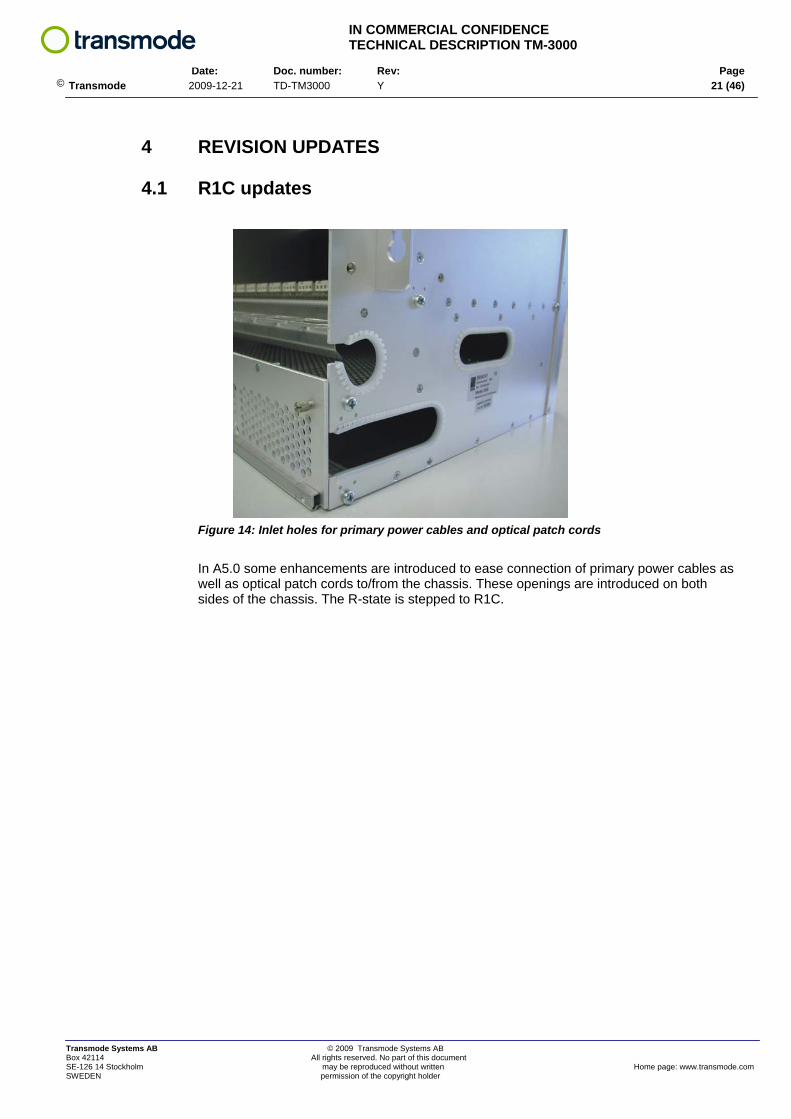
Figure 14: Inlet holes for primary power cables and optical patch cords
In A5.0 some enhancements are introduced to ease connection of primary power cables as well as optical patch cords to/from the chassis. These openings are introduced on both sides of the chassis. The R-state is stepped to R1C.
Transmode Systems AB © 2009 Transmode Systems AB Box 42114 All rights reserved. No part of this document SE-126 14 Stockholm may be reproduced without written Home page: www.transmode.com SWEDEN permission of the copyright holder
IN COMMERCIAL CONFIDENCE TECHNICAL DESCRIPTION TM-3000
Date: Doc. number: Rev: Page
© Transmode 2009-12-21 TD-TM3000 Y 22 (46)
4.2 R2A update
The R2A revision has passed through NEBS testing for the US market. Some mechanical solutions have changed as a result, but functionality wise there is no change. All delivered chassis are R2A regardless of market.
4.3 R3A updates
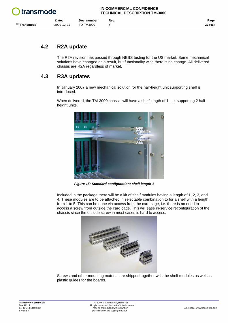
In January 2007 a new mechanical solution for the half-height unit supporting shelf is introduced.
When delivered, the TM-3000 chassis will have a shelf length of 1, i.e. supporting 2 half-height units.
Figure 15: Standard configuration; shelf length 1
Included in the package there will be a kit of shelf modules having a length of 1, 2, 3, and 4. These modules are to be attached in selectable combination to for a shelf with a length from 1 to 5. This can be done via access from the card cage, i.e. there is no need to access a screw from outside the card cage. This will ease in-service reconfiguration of the chassis since the outside screw in most cases is hard to access.
Screws and other mounting material are shipped together with the shelf modules as well as plastic guides for the boards.
Transmode Systems AB © 2009 Transmode Systems AB Box 42114 All rights reserved. No part of this document SE-126 14 Stockholm may be reproduced without written Home page: www.transmode.com SWEDEN permission of the copyright holder

IN COMMERCIAL CONFIDENCE TECHNICAL DESCRIPTION TM-3000
Date: Doc. number: Rev: Page
© Transmode 2009-12-21 TD-TM3000 Y 23 (46)
A new plastic cover for the card cage is also added.
This cover is deep enough to be used for equipped configurations, i.e. it has space enough for the patch cords so that these are not squeezed in a way that can introduce micro bends resulting in optical losses.
The cover can be flipped open as shown in the figure. It will stay in the open position via tabs that rest on the card cage frame.
When closing the cover it is important to press in the tabs before closing the cover. If not, the tabs will eventually be damaged and the cover will no longer stay in the open position.
The cover can easily be remove completely and reinserted.
Transmode Systems AB © 2009 Transmode Systems AB Box 42114 All rights reserved. No part of this document SE-126 14 Stockholm may be reproduced without written Home page: www.transmode.com SWEDEN permission of the copyright holder

IN COMMERCIAL CONFIDENCE TECHNICAL DESCRIPTION TM-3000
Date: Doc. number: Rev: Page
© Transmode 2009-12-21 TD-TM3000 Y 24 (46)
4.4 R4 updates
The following improvements/changes are introduced on the R4 version:
• New fan module: Current fan module contains one fan unit. The new fan module will include three fan units. The new fan module will provide the following benefits: - improved air flow - to maintain high air flow upon a fan unit failure - to enable -60V DC primary power supply solutions (future) - reduced noise level - reduced weight from 2kg to 0,9 kg per fan module - reduced power consumption from ~48W to ~17W per fan module.
• Introduction of fiber management solution on the upper part of the card cage to ease placement/routing of optical patch cords in high channel configurations.
• Introduction of a new air filters to ease replacement. The new filters cover half the card cage. Current filter is a singular solution expanding over the whole card cage. The new solution will no longer be required to remove lower fiber management mechanics when extracting the air filters.
• Adjusted and improved solution for fiber management beneath the card cage.
The following compatibility restrictions exist:
• Existing fan modules used in TM-3000 chassis R3A (or older) can be used in new R4A. • New fan modules of R4A cannot be used in R3A (or older). • Existing air filters used in TM-3000 chassis R3A (or older) cannot be used in new R4A. • New air filters of R4A cannot be used in R3A or older.
To conclude; R3A and older versions must continue to use existing fan modules and air filters. These will continue to be available as spare parts until further notice.
There are no compatibility restrictions in terms of active or passive plug-in units.
Transmode Systems AB © 2009 Transmode Systems AB Box 42114 All rights reserved. No part of this document SE-126 14 Stockholm may be reproduced without written Home page: www.transmode.com SWEDEN permission of the copyright holder
IN COMMERCIAL CONFIDENCE TECHNICAL DESCRIPTION TM-3000
Date: Doc. number: Rev: Page
© Transmode 2009-12-21 TD-TM3000 Y 25 (46)
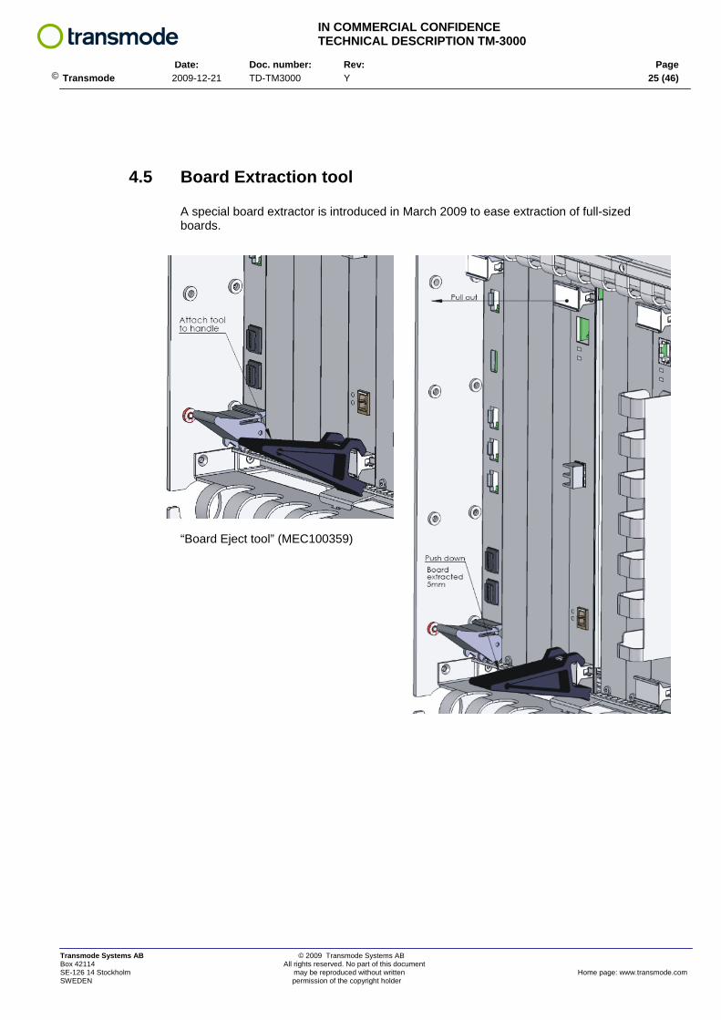
4.5 Board Extraction tool
A special board extractor is introduced in March 2009 to ease extraction of full-sized boards.
“Board Eject tool” (MEC100359)
Transmode Systems AB © 2009 Transmode Systems AB Box 42114 All rights reserved. No part of this document SE-126 14 Stockholm may be reproduced without written Home page: www.transmode.com SWEDEN permission of the copyright holder

IN COMMERCIAL CONFIDENCE TECHNICAL DESCRIPTION TM-3000
Date: Doc. number: Rev: Page
© Transmode 2009-12-21 TD-TM3000 Y 26 (46)
5 LABELS
The TM-3000 chassis is marked with a Product Label and a System Label. Both are placed on the top of the chassis, on the left, front side.
The Product label contains:
1. Transmode logotype 2. Product number 3. Product revision 4. Barcode 128 containing: product number “space” revision 5. Production date: yearWweeknumber 6. Serial number 7. Barcode 128 containing: serial number 8. Barcode 128 containing: product number, revision, production date, serial number 9. Approval markings
This information is not accessible via the inventory function in the management system. Inventory data on CU’s and Traffic Units are available via the inventory functionality.
4
M3000/ENC Rev:R1C
7
8
Transmode Systems AB © 2009 Transmode Systems AB Box 42114 All rights reserved. No part of this document SE-126 14 Stockholm may be reproduced without written Home page: www.transmode.com SWEDEN permission of the copyright holder
IN COMMERCIAL CONFIDENCE TECHNICAL DESCRIPTION TM-3000
Date: Doc. number: Rev: Page
© Transmode 2009-12-21 TD-TM3000 Y 27 (46)
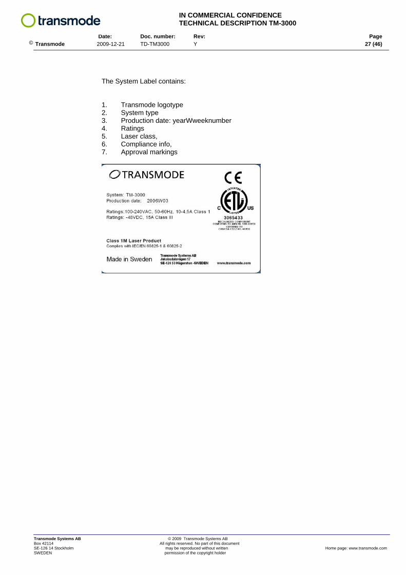
The System Label contains: 1. Transmode logotype 2. System type 3. Production date: yearWweeknumber 4. Ratings 5. Laser class, 6. Compliance info, 7. Approval markings
Transmode Systems AB © 2009 Transmode Systems AB Box 42114 All rights reserved. No part of this document SE-126 14 Stockholm may be reproduced without written Home page: www.transmode.com SWEDEN permission of the copyright holder
IN COMMERCIAL CONFIDENCE TECHNICAL DESCRIPTION TM-3000
Date: Doc. number: Rev: Page
© Transmode 2009-12-21 TD-TM3000 Y 28 (46)
6 TECHNICAL DATA Table 7: Mechanical & electrical data
TM-3000 Height 10,35U / 460mm Depth 298mm Width (excl. mounting brackets) 445mm
Primary Power DC-inlets. Redundant, Hot-swap
Cooling Redundant fans. Hot-swap
Mounting ETSI, 19”, 23” Fiber management Yes LAN/Mgmt connections RJ45 Primary power range DC: -40,8 to -57,6VDC 15A Class III Max power at DC powering 600 W
Max Inrush current @ -48VDC 41,1A / 1,5ms when using DC/DC module R1E 18,8A / 0,2ms when using DC/DC module R1F
Primary power range AC 100-240VAC 50/60Hz, 2.5A, Class I Max power at AC powering 700 W
Size AC/DC converter AC-DC-1RU-750 R2 Rack mount Height: 1U / 44 mm
Max power consumption in card cage ~420W
Weight DC-powering: 18 kg (mechanics + 2x fan unit + 2x DC inlet module + LAN module
DC cable size 1,5mm2
(connector limit) Standard 1,0mm2
Operating conditions ETSI EN 300 019-1-3 class T3.1
Table 8: Capacity
TM-3000 Number of full-height slots1) Up to 16 Number of half-height slots2) Up to 10 No of λ in largest possible configuration3)
40 CWDM or 40 DWDM
1) Slots for Traffic units (Transponders/MuxPonders) 25mm width, 262mm length 2) Slots for passive units (Add/drop filters, MDU’s), 25mm width, 129mm length 3) Includes both Traffic units and passive unit within one chassis. Larger nodes are created using multiple chassis
Note: The TM-3000 chassis can mechanically be configured between to extremes: 16x “full-slots” + 0x “half-slots” 11x “full-slots” + 10x “half-slots”
Transmode Systems AB © 2009 Transmode Systems AB Box 42114 All rights reserved. No part of this document SE-126 14 Stockholm may be reproduced without written Home page: www.transmode.com SWEDEN permission of the copyright holder
IN COMMERCIAL CONFIDENCE TECHNICAL DESCRIPTION TM-3000
Date: Doc. number: Rev: Page
© Transmode 2009-12-21 TD-TM3000 Y 29 (46)
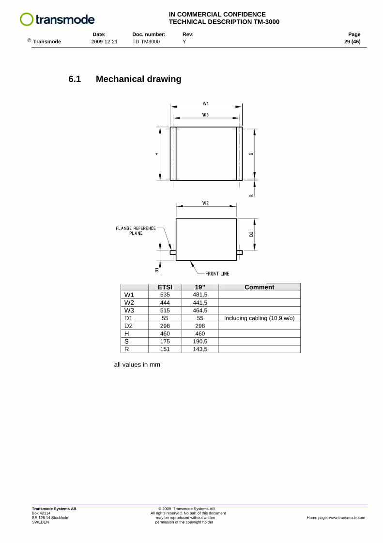
6.1 Mechanical drawing
ETSI 19” Comment W1 535 481,5 W2 444 441,5 W3 515 464,5 D1 55 55 Including cabling (10,9 w/o) D2 298 298 H 460 460 S 175 190,5 R 151 143,5
all values in mm
Transmode Systems AB © 2009 Transmode Systems AB Box 42114 All rights reserved. No part of this document SE-126 14 Stockholm may be reproduced without written Home page: www.transmode.com SWEDEN permission of the copyright holder

IN COMMERCIAL CONFIDENCE TECHNICAL DESCRIPTION TM-3000
Date: Doc. number: Rev: Page
© Transmode 2009-12-21 TD-TM3000 Y 30 (46)
6.2 Revision data A TM-3000 chassis has an order level that includes mechanics, cables, Control Unit etc as listed in chapter 6.3. The table shows revision data on “M3000/ENC” which is the basic card cage mechanics. Changes in this basic mechanics is reflected on the M3000/ENC level. Table 9: Revision data
Product number Rev Introduced Release
R1B A1.0 1st released version
R1C A5.0 Openings on sides to ease insert of primary power cables and optical patch cords.
R2A 7.0 NEBS approved
R3A 10.0 New mechanical shelf plus card cage cover
M3000/ENC
R4A 13.0 See chapter 4.4
R1B A1.0 1st released version
M3000/DAC/19, /ETSI R1C A4.0 Terminated, replaced by DC version with external AC/DC module
The revision of a TM-3000 chassis is displayed on the label, placed on the top of the card cage. See chapter 5. In release 13.0 (June 2009) an updated version of the DC/DC module is introduced. The R-stage is stepped from R1E to R1F. See chapter 2.3.3.1 for details.
Transmode Systems AB © 2009 Transmode Systems AB Box 42114 All rights reserved. No part of this document SE-126 14 Stockholm may be reproduced without written Home page: www.transmode.com SWEDEN permission of the copyright holder

IN COMMERCIAL CONFIDENCE TECHNICAL DESCRIPTION TM-3000
Date: Doc. number: Rev: Page
© Transmode 2009-12-21 TD-TM3000 Y 31 (46)
6.3 Ordering data When ordering a TM-3000 chassis, the deliverable is a “Basic NE-Equipment”. A Basic NE Equipment includes everything that is needed to create a Network Element, apart from Traffic plug-in units (Transponders/Muxponders etc) and Passive units (optical filters etc). Six different configuration alternatives are provided when ordering TM-3000 chassis; two different power alternatives and three different mounting alternatives. Table 10: Configuration alternatives Basic NE-Equipment TM-3000
Configuration Ordering code TM-3000, DC 19 TM3000DC19 TM-3000, AC, 19 TM3000AC19 TM-3000, DC, ETSI TM3000DCET TM-3000, AC, ETSI TM3000ACET TM-3000, DC, 23” TM3000DC23 TM-3000, AC, 23” TM3000AC23 If OSC channels are needed, suitable SFP’s must added. See “Dimensioning Guidelines” within the system manual for more details. At delivery the TM-3000 chassis is configured for 15 full-height and 2 half-height plug-in units (i.e. with a shelf length of one card slot). See also chapter 4.3.
The above ordering numbers include the following items: • TM-3000 card cage • Control Unit CU-SFP (1 per chassis) • DC/DC filter module (2 items per chassis) • AC/DC converter 115/230V 750W (1 per chassis, only for AC configuration, 19”/ETSI mount) • LAN module / RJ 45 card (1 per chassis) • Front cover (1 per chassis) • Air guides, full-height (13 items) • Air guides, half-height (1 item) • Dummy panels, full-height (14 items) • Dummy panels, half-height (2 items) • DC cable, 4m (2 items) • Ethernet cable, 2m (1 item) • DSUB adapter RJ45/DB9 (1 item) • ESD wrist wrap with strap (1 item) • Mounting material in rack; nuts, plastic plates, screws (8 sets) • Extra dummy panels, half-height (4 items) • Extra air guides, half-height (1 item) • Shelf-kit with mounting material • Mounting brackets 19” (mounted, 2 per chassis) • Mounting brackets ETSI (2 per chassis, only in ETSI version) • Mounting brackets 23” (2 per chassis, only in 23”version) • “Board Eject tool” (MEC100359)
Transmode Systems AB © 2009 Transmode Systems AB Box 42114 All rights reserved. No part of this document SE-126 14 Stockholm may be reproduced without written Home page: www.transmode.com SWEDEN permission of the copyright holder
IN COMMERCIAL CONFIDENCE TECHNICAL DESCRIPTION TM-3000
Date: Doc. number: Rev: Page
© Transmode 2009-12-21 TD-TM3000 Y 32 (46)
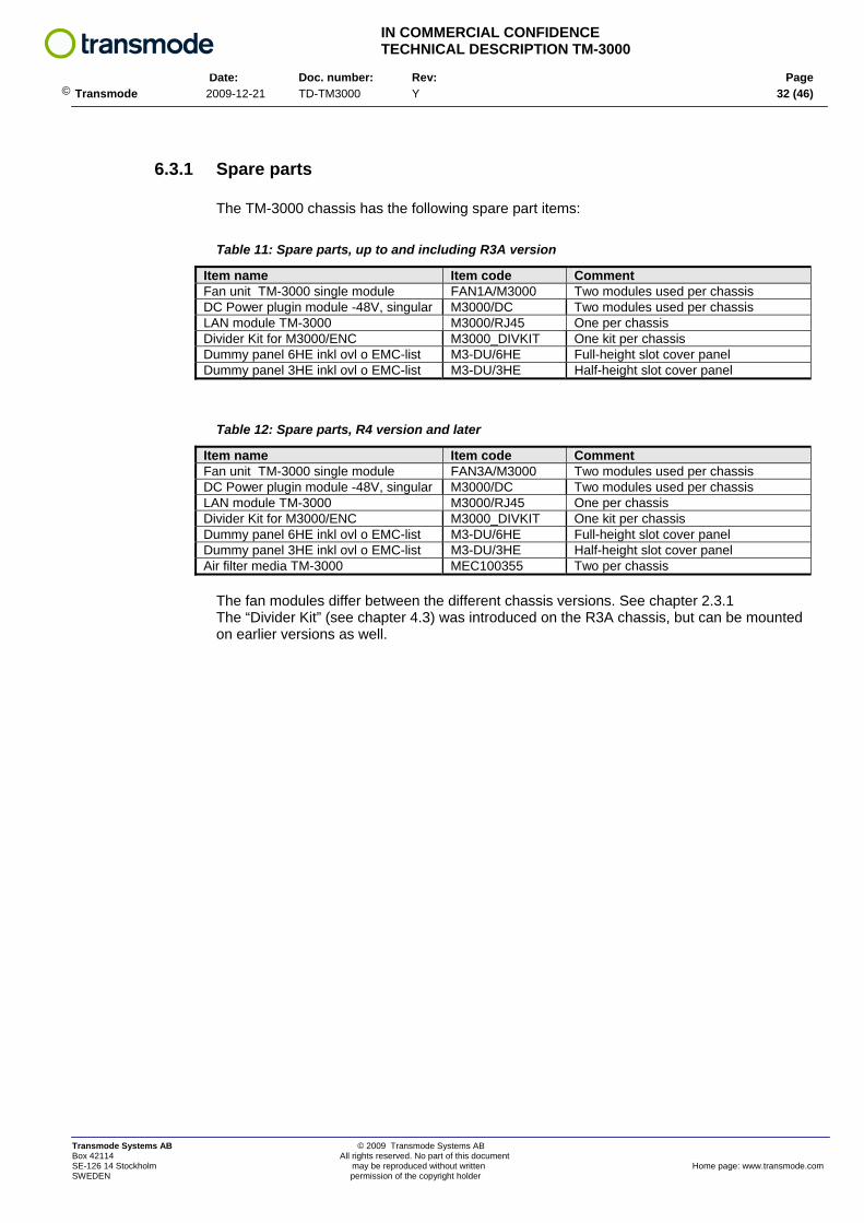
6.3.1 Spare parts The TM-3000 chassis has the following spare part items:
Table 11: Spare parts, up to and including R3A version
Item name Item code Comment Fan unit TM-3000 single module FAN1A/M3000 Two modules used per chassis DC Power plugin module -48V, singular M3000/DC Two modules used per chassis LAN module TM-3000 M3000/RJ45 One per chassis Divider Kit for M3000/ENC M3000_DIVKIT One kit per chassis Dummy panel 6HE inkl ovl o EMC-list M3-DU/6HE Full-height slot cover panel Dummy panel 3HE inkl ovl o EMC-list M3-DU/3HE Half-height slot cover panel
Table 12: Spare parts, R4 version and later
Item name Item code Comment Fan unit TM-3000 single module FAN3A/M3000 Two modules used per chassis DC Power plugin module -48V, singular M3000/DC Two modules used per chassis LAN module TM-3000 M3000/RJ45 One per chassis Divider Kit for M3000/ENC M3000_DIVKIT One kit per chassis Dummy panel 6HE inkl ovl o EMC-list M3-DU/6HE Full-height slot cover panel Dummy panel 3HE inkl ovl o EMC-list M3-DU/3HE Half-height slot cover panel Air filter media TM-3000 MEC100355 Two per chassis
The fan modules differ between the different chassis versions. See chapter 2.3.1 The “Divider Kit” (see chapter 4.3) was introduced on the R3A chassis, but can be mounted on earlier versions as well.
Transmode Systems AB © 2009 Transmode Systems AB Box 42114 All rights reserved. No part of this document SE-126 14 Stockholm may be reproduced without written Home page: www.transmode.com SWEDEN permission of the copyright holder
IN COMMERCIAL CONFIDENCE TECHNICAL DESCRIPTION TM-3000
Date: Doc. number: Rev: Page
© Transmode 2009-12-21 TD-TM3000 Y 33 (46)
7 APPENDIX
7.1 TM-3000 Configurations
The TM-3000 chassis can be ordered with different number of half-height slots. This is defined by a shelf length that provides mechanical support for two half-height units in a full-height slot.
Up to 10 half-height slots can be created using a shelf length of 5.
The first full-height slot is for CU only.
The following recommendations can be stated:
• Configurations for up to 40 DWDM channels will typically require a half-size slot length 1, giving two half-sized slots.
• 80ch configurations will typically require a shelf length of 2, giving four half-sized slots.
• Mixed CWDM/DWDM configurations or configurations with equipment protection will require more half-sized slots.
The actual relationship between full-sized and half-sized slots is thus dependent on the actual node configuration.
The total power consumption within the card cage must be less than ~420W. For high power consuming units, this will set a restriction on how many units you can insert in a card cage.
Transmode Systems AB © 2009 Transmode Systems AB Box 42114 All rights reserved. No part of this document SE-126 14 Stockholm may be reproduced without written Home page: www.transmode.com SWEDEN permission of the copyright holder
IN COMMERCIAL CONFIDENCE TECHNICAL DESCRIPTION TM-3000
Date: Doc. number: Rev: Page
© Transmode 2009-12-21 TD-TM3000 Y 34 (46)
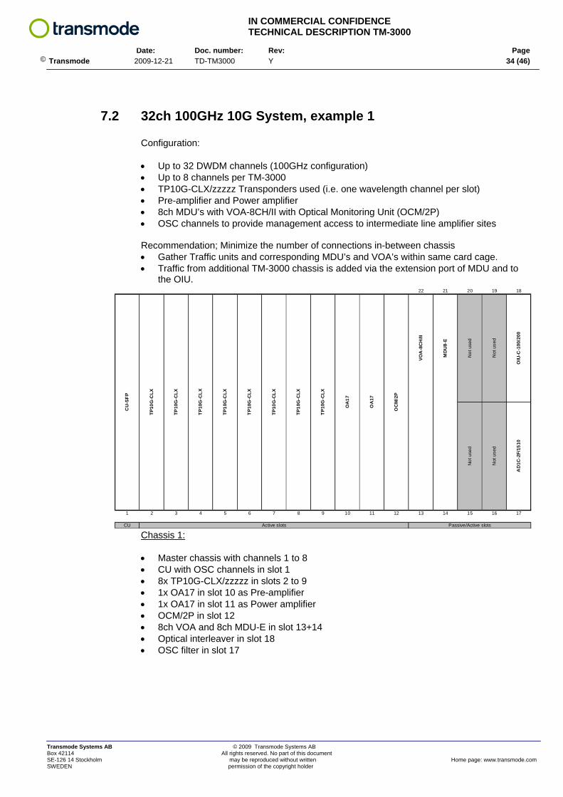
7.2 32ch 100GHz 10G System, example 1
Configuration:
• Up to 32 DWDM channels (100GHz configuration) • Up to 8 channels per TM-3000 • TP10G-CLX/zzzzz Transponders used (i.e. one wavelength channel per slot) • Pre-amplifier and Power amplifier • 8ch MDU’s with VOA-8CH/II with Optical Monitoring Unit (OCM/2P) • OSC channels to provide management access to intermediate line amplifier sites Recommendation; Minimize the number of connections in-between chassis • Gather Traffic units and corresponding MDU’s and VOA’s within same card cage. • Traffic from additional TM-3000 chassis is added via the extension port of MDU and to
the OIU.
Chassis 1:
22 21 20 19 18
1 2 3 4 5 6 7 8 9 10 11 12 13 14 15 16 17
CU
CU
-SFP
TP10
G-C
LX
TP10
G-C
LX
TP10
G-C
LX
TP10
G-C
LX
TP10
G-C
LX
TP10
G-C
LX
TP10
G-C
LX
MD
U8-
E
Not
use
d
TP10
G-C
LX
OA
17
OA
17
OC
M/2
P
OIU
-C-1
00/2
00A
D1C
-2F/
1510
Passive/Active slotsActive slots
Not
use
d
Not
use
d
Not
use
d
VOA
-8C
H/II
• Master chassis with channels 1 to 8 • CU with OSC channels in slot 1 • 8x TP10G-CLX/zzzzz in slots 2 to 9 • 1x OA17 in slot 10 as Pre-amplifier • 1x OA17 in slot 11 as Power amplifier • OCM/2P in slot 12 • 8ch VOA and 8ch MDU-E in slot 13+14 • Optical interleaver in slot 18 • OSC filter in slot 17
Transmode Systems AB © 2009 Transmode Systems AB Box 42114 All rights reserved. No part of this document SE-126 14 Stockholm may be reproduced without written Home page: www.transmode.com SWEDEN permission of the copyright holder
IN COMMERCIAL CONFIDENCE TECHNICAL DESCRIPTION TM-3000
Date: Doc. number: Rev: Page
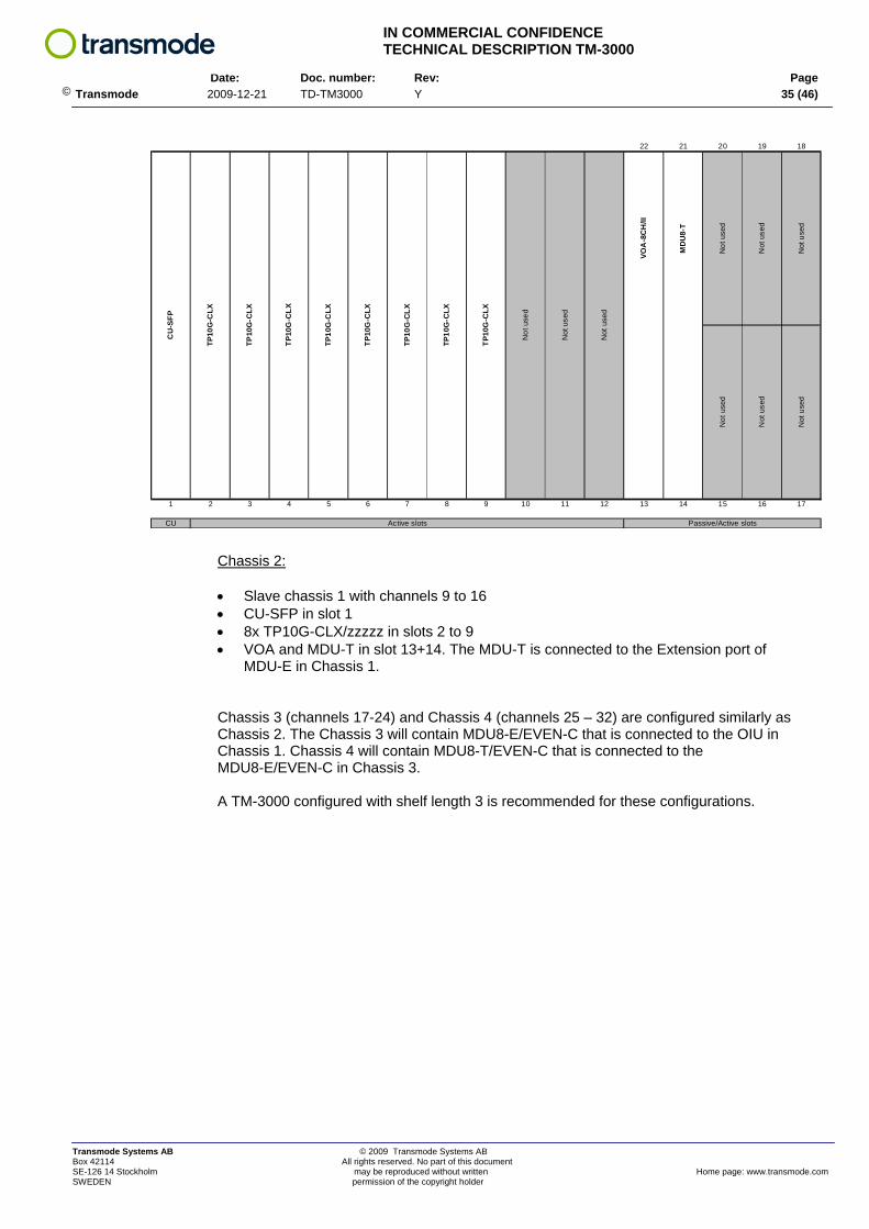
© Transmode 2009-12-21 TD-TM3000 Y 35 (46)
Chassis 2:
22 21 20 19 18
1 2 3 4 5 6 7 8 9 10 11 12 13 14 15 16 17
CU
CU
-SFP
TP10
G-C
LX
TP10
G-C
LX
TP10
G-C
LX
TP10
G-C
LX
TP10
G-C
LX
TP10
G-C
LX
TP10
G-C
LX
Not
use
d
Not
use
d
TP10
G-C
LX
Not
use
d
Not
use
d
Not
use
d
Active slots Passive/Active slots
Not
use
d
Not
use
d
Not
use
d
Not
use
d
VOA
-8C
H/II
MD
U8-
T
• Slave chassis 1 with channels 9 to 16 • CU-SFP in slot 1 • 8x TP10G-CLX/zzzzz in slots 2 to 9 • VOA and MDU-T in slot 13+14. The MDU-T is connected to the Extension port of
MDU-E in Chassis 1.
Chassis 3 (channels 17-24) and Chassis 4 (channels 25 – 32) are configured similarly as Chassis 2. The Chassis 3 will contain MDU8-E/EVEN-C that is connected to the OIU in Chassis 1. Chassis 4 will contain MDU8-T/EVEN-C that is connected to the MDU8-E/EVEN-C in Chassis 3. A TM-3000 configured with shelf length 3 is recommended for these configurations.
Transmode Systems AB © 2009 Transmode Systems AB Box 42114 All rights reserved. No part of this document SE-126 14 Stockholm may be reproduced without written Home page: www.transmode.com SWEDEN permission of the copyright holder

IN COMMERCIAL CONFIDENCE TECHNICAL DESCRIPTION TM-3000
Date: Doc. number: Rev: Page
© Transmode 2009-12-21 TD-TM3000 Y 36 (46)
7.3 32ch 100GHz 10G System, example 2
Configuration:
• Up to 32 channels • Up to 16 channels per TM-3000 • TPD10GBE-BU Transponders used (i.e. two wavelength channels per slot) • Pre-amplifier and Power amplifier • 8ch MDU’s with VOA’s and OCM/2P • OSC channel for management access to line amplifier nodes Recommendation; Minimize the number of connections in-between chassis • Gather Traffic units and corresponding MDU’s and VOA’s within same card cage. • Traffic from additional TM-3000 chassis is added via the extension port of MDU or to
the OIU.
Chassis 1:
22 21 20 19 18
1 2 3 4 5 6 7 8 9 10 11 12 13 14 15 16 17
CU
CU
-SFP
with
SFP
for
OSC
cha
nnel
TPD
10G
BE-
BU
TPD
10G
BE-
BU
TPD
10G
BE
-BU
Dou
ble
OA
20 (P
re-a
mp
+ B
oost
er)
OC
M/2
P
TPD
10G
BE-
BU
TPD
10G
BE-
BU
TPD
10G
BE-
BU
TPD
10G
BE-
BU
TPD
10G
BE-
BU
Not
use
d
OIU
-C-1
00/2
00A
D1C
-2F/
1510
VOA
-8C
H/II
MD
U8-
E
VOA
-8C
H/II
MD
U8-
T
Active slots Passive/Active slots
• Master chassis with channels 1 to 16 • CU with OSC channel in slot 1 • 8x TPD10G-L in slots 2 to 9 giving 16 DWDM channels • 1x 2xOA20 in slot 11 as Power and Pre-amplifier • OCM/2P in slot 12 • 8ch VOA and 8ch MDU-E in slot 13+14 and 15+16 • Optical interleaver in slot 18 • OSC filter in slot 17
Transmode Systems AB © 2009 Transmode Systems AB Box 42114 All rights reserved. No part of this document SE-126 14 Stockholm may be reproduced without written Home page: www.transmode.com SWEDEN permission of the copyright holder
IN COMMERCIAL CONFIDENCE TECHNICAL DESCRIPTION TM-3000
Date: Doc. number: Rev: Page
© Transmode 2009-12-21 TD-TM3000 Y 37 (46)
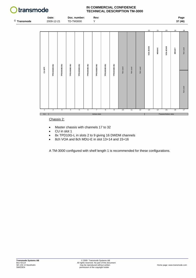
Chassis 2:
22 21 20 19 18
1 2 3 4 5 6 7 8 9 10 11 12 13 14 15 16 17
CU
CU
-SFP
TPD
10G
BE-
BU
TPD
10G
BE-
BU
TPD
10G
BE
-BU
TPD
10G
BE-
BU
TPD
10G
BE-
BU
TPD
10G
BE-
BU
TPD
10G
BE-
BU
VOA
-8C
H/II
MD
U8-
T
TPD
10G
BE-
BU
Not
use
d
Not
use
d
Not
use
d
Active slots Passive/Active slots
Not
use
dN
ot u
sed
VOA
-8C
H/II
MD
U8-
E
• Master chassis with channels 17 to 32 • CU in slot 1 • 8x TPD10G-L in slots 2 to 9 giving 16 DWDM channels • 8ch VOA and 8ch MDU-E in slot 13+14 and 15+16 A TM-3000 configured with shelf length 1 is recommended for these configurations.
Transmode Systems AB © 2009 Transmode Systems AB Box 42114 All rights reserved. No part of this document SE-126 14 Stockholm may be reproduced without written Home page: www.transmode.com SWEDEN permission of the copyright holder
IN COMMERCIAL CONFIDENCE TECHNICAL DESCRIPTION TM-3000
Date: Doc. number: Rev: Page
© Transmode 2009-12-21 TD-TM3000 Y 38 (46)
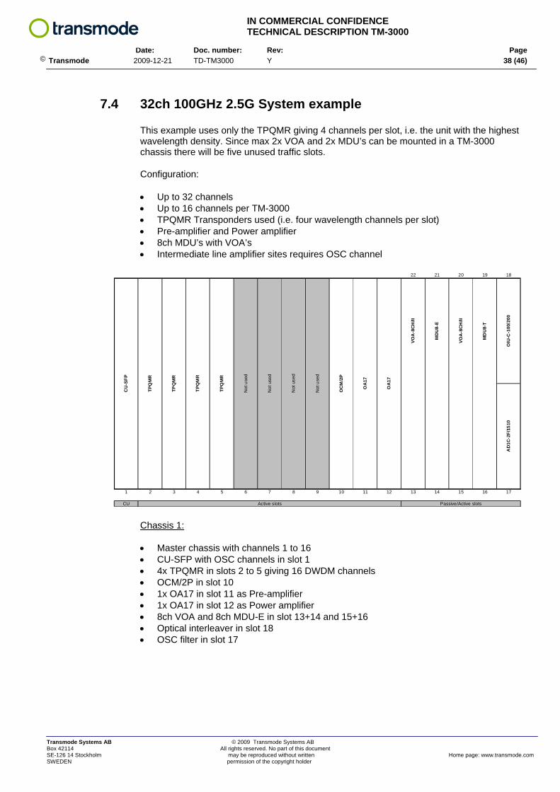
7.4 32ch 100GHz 2.5G System example This example uses only the TPQMR giving 4 channels per slot, i.e. the unit with the highest wavelength density. Since max 2x VOA and 2x MDU’s can be mounted in a TM-3000 chassis there will be five unused traffic slots.
Configuration:
• Up to 32 channels • Up to 16 channels per TM-3000 • TPQMR Transponders used (i.e. four wavelength channels per slot) • Pre-amplifier and Power amplifier • 8ch MDU’s with VOA’s • Intermediate line amplifier sites requires OSC channel
Chassis 1:
22 21 20 19 18
1 2 3 4 5 6 7 8 9 10 11 12 13 14 15 16 17
CU
CU
-SFP
TPQ
MR
TPQ
MR
TPQ
MR
OA
17
OA
17
TPQ
MR
Not
use
d
Not
use
d
Not
use
d
Not
use
d
OC
M/2
P
OIU
-C-1
00/2
00A
D1C
-2F/
1510
VOA
-8C
H/II
MD
U8-
E
VOA
-8C
H/II
MD
U8-
T
Active slots Passive/Active slots
• Master chassis with channels 1 to 16 • CU-SFP with OSC channels in slot 1 • 4x TPQMR in slots 2 to 5 giving 16 DWDM channels • OCM/2P in slot 10 • 1x OA17 in slot 11 as Pre-amplifier • 1x OA17 in slot 12 as Power amplifier • 8ch VOA and 8ch MDU-E in slot 13+14 and 15+16 • Optical interleaver in slot 18 • OSC filter in slot 17
Transmode Systems AB © 2009 Transmode Systems AB Box 42114 All rights reserved. No part of this document SE-126 14 Stockholm may be reproduced without written Home page: www.transmode.com SWEDEN permission of the copyright holder

IN COMMERCIAL CONFIDENCE TECHNICAL DESCRIPTION TM-3000
Date: Doc. number: Rev: Page
© Transmode 2009-12-21 TD-TM3000 Y 39 (46)
Chassis 2:
22 21 20 19 18
1 2 3 4 5 6 7 8 9 10 11 12 13 14 15 16 17
CU
CU
-SFP
TPQ
MR
TPQ
MR
TPQ
MR
TPQ
MR
Not
use
d
Not
use
d
Not
use
d
VOA
-8C
H/II
MD
U8-
T/EV
EN-C
Not
use
d
Not
use
d
Not
use
d
Not
use
d
Active slots Passive/Active slots
Not
use
dN
ot u
sed
VOA
-8C
H/II
MD
U8-
E/EV
EN-C
• Slave chassis with channels 17 to 32 • CU-SFP in slot 1 • 4x TPQMR in slots 2 to 5 giving 16 DWDM channels • 8ch VOA and 8ch MDU-E/EVEN + MDU-T/EVEN in slot 13+14 and 15+16 As seen a number of slots will be un-used for this example configuration. Normally a mix of traffic units is used and thus fewer slots will be un-used.
Transmode Systems AB © 2009 Transmode Systems AB Box 42114 All rights reserved. No part of this document SE-126 14 Stockholm may be reproduced without written Home page: www.transmode.com SWEDEN permission of the copyright holder
IN COMMERCIAL CONFIDENCE TECHNICAL DESCRIPTION TM-3000
Date: Doc. number: Rev: Page
© Transmode 2009-12-21 TD-TM3000 Y 40 (46)
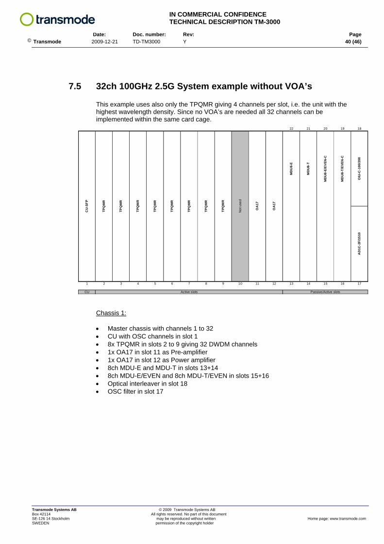
7.5 32ch 100GHz 2.5G System example without VOA’s This example uses also only the TPQMR giving 4 channels per slot, i.e. the unit with the highest wavelength density. Since no VOA’s are needed all 32 channels can be implemented within the same card cage.
Chassis 1:
22 21 20 19 18
1 2 3 4 5 6 7 8 9 10 11 12 13 14 15 16 17
CU
CU
-SFP
TPQ
MR
TPQ
MR
TPQ
MR
TPQ
MR
TPQ
MR
OIU
-C-1
00/2
00
TPQ
MR
TPQ
MR
TPQ
MR
Not
use
d
OA
17
OA
17
MD
U8-
E
MD
U8-
T
MD
U8-
E/EV
EN-C
MD
U8-
T/EV
EN-C
AD
1C-2
F/15
10
Active slots Passive/Active slots
• Master chassis with channels 1 to 32 • CU with OSC channels in slot 1 • 8x TPQMR in slots 2 to 9 giving 32 DWDM channels • 1x OA17 in slot 11 as Pre-amplifier • 1x OA17 in slot 12 as Power amplifier • 8ch MDU-E and MDU-T in slots 13+14 • 8ch MDU-E/EVEN and 8ch MDU-T/EVEN in slots 15+16 • Optical interleaver in slot 18 • OSC filter in slot 17
Transmode Systems AB © 2009 Transmode Systems AB Box 42114 All rights reserved. No part of this document SE-126 14 Stockholm may be reproduced without written Home page: www.transmode.com SWEDEN permission of the copyright holder
IN COMMERCIAL CONFIDENCE TECHNICAL DESCRIPTION TM-3000
Date: Doc. number: Rev: Page
© Transmode 2009-12-21 TD-TM3000 Y 41 (46)
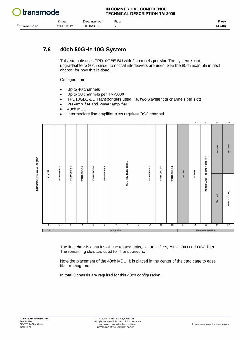
7.6 40ch 50GHz 10G System This example uses TPD10GBE-BU with 2 channels per slot. The system is not upgradeable to 80ch since no optical interleavers are used. See the 80ch example in next chapter for how this is done.
Configuration:
• Up to 40 channels • Up to 18 channels per TM-3000 • TPD10GBE-BU Transponders used (i.e. two wavelength channels per slot) • Pre-amplifier and Power amplifier • 40ch MDU • Intermediate line amplifier sites requires OSC channel
The first chassis contains all line related units, i.e. amplifiers, MDU, OIU and OSC filter. The remaining slots are used for Transponders.
Note the placement of the 40ch MDU, It is placed in the center of the card cage to ease fiber management.
In total 3 chassis are required for this 40ch configuration.
22 21 20 19 18
1 2 3 4 5 6 7 8 9 10 11 12 13 14 15 16 17
CU
Dou
ble
OA
20 (P
re-a
mp
+ B
oost
er)
40ch
MD
U E
VEN
50G
Hz
TPD
10G
BE-
BU
TPD
10G
BE
-BU
TPD
10G
BE-
BU
Not
use
d
OC
M/2
P
Cha
ssis
1: 1
6 w
avel
engt
hs
TPD
10G
BE-
BU
TPD
10G
BE-
BU
Not
use
dA
D1C
-2F/
1510
)
Not
use
dN
ot u
sed
Passive/Active slots
CU
-SFP
TPD
10G
BE-
BU
TPD
10G
BE
-BU
TPD
10G
BE-
BU
Active slots
Transmode Systems AB © 2009 Transmode Systems AB Box 42114 All rights reserved. No part of this document SE-126 14 Stockholm may be reproduced without written Home page: www.transmode.com SWEDEN permission of the copyright holder
IN COMMERCIAL CONFIDENCE TECHNICAL DESCRIPTION TM-3000
Date: Doc. number: Rev: Page
© Transmode 2009-12-21 TD-TM3000 Y 42 (46)
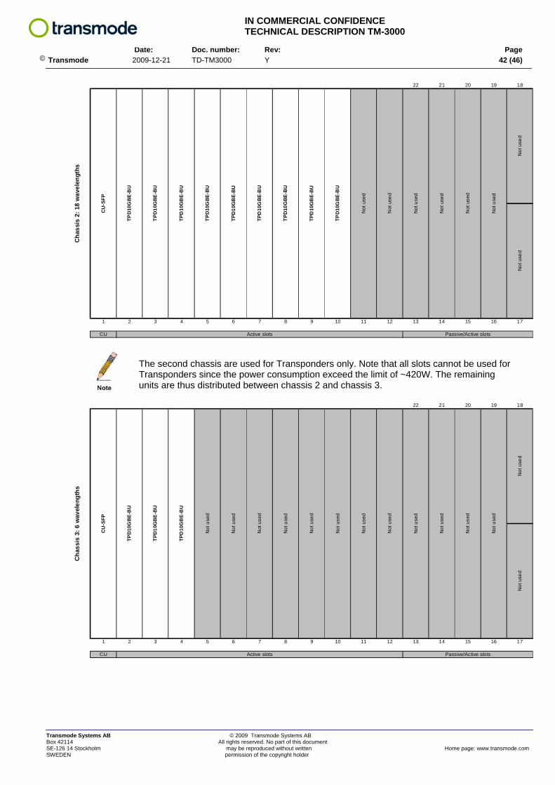
The second chassis are used for Transponders only. Note that all slots cannot be used for Transponders since the power consumption exceed the limit of ~420W. The remaining units are thus distributed between chassis 2 and chassis 3.
22 21 20 19 18
1 2 3 4 5 6 7 8 9 10 11 12 13 14 15 16 17
CU
TPD
10G
BE-
BU
Active slots
Not
use
d
Not
use
d
Cha
ssis
2: 1
8 w
avel
engt
hs
Not
use
d
TPD
10G
BE-
BU
TPD
10G
BE-
BU
TPD
10G
BE-
BU
Passive/Active slots
Not
use
dN
ot u
sed
Not
use
d
Not
use
d
TPD
10G
BE-
BU
TPD
10G
BE-
BU
Not
use
d
CU
-SFP
TPD
10G
BE
-BU
TPD
10G
BE-
BU
TPD
10G
BE-
BU
22 21 20 19 18
1 2 3 4 5 6 7 8 9 10 11 12 13 14 15 16 17
CU
Not
use
dN
ot u
sed
Active slots Passive/Active slots
Not
use
d
Not
use
d
Not
use
d
Not
use
d
Not
use
d
Not
use
d
Not
use
d
Not
use
d
Cha
ssis
3: 6
wav
elen
gths
CU
-SFP
TPD
10G
BE-
BU
TPD
10G
BE
-BU
TPD
10G
BE-
BU
Not
use
d
Not
use
d
Not
use
d
Not
use
d
Transmode Systems AB © 2009 Transmode Systems AB Box 42114 All rights reserved. No part of this document SE-126 14 Stockholm may be reproduced without written Home page: www.transmode.com SWEDEN permission of the copyright holder
IN COMMERCIAL CONFIDENCE TECHNICAL DESCRIPTION TM-3000
Date: Doc. number: Rev: Page
© Transmode 2009-12-21 TD-TM3000 Y 43 (46)
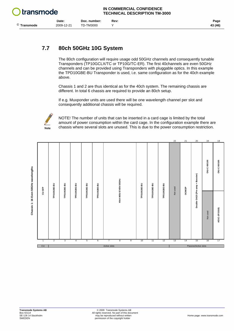
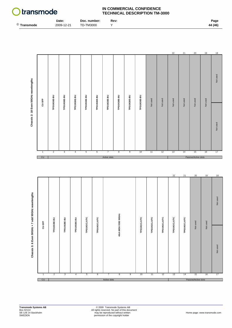
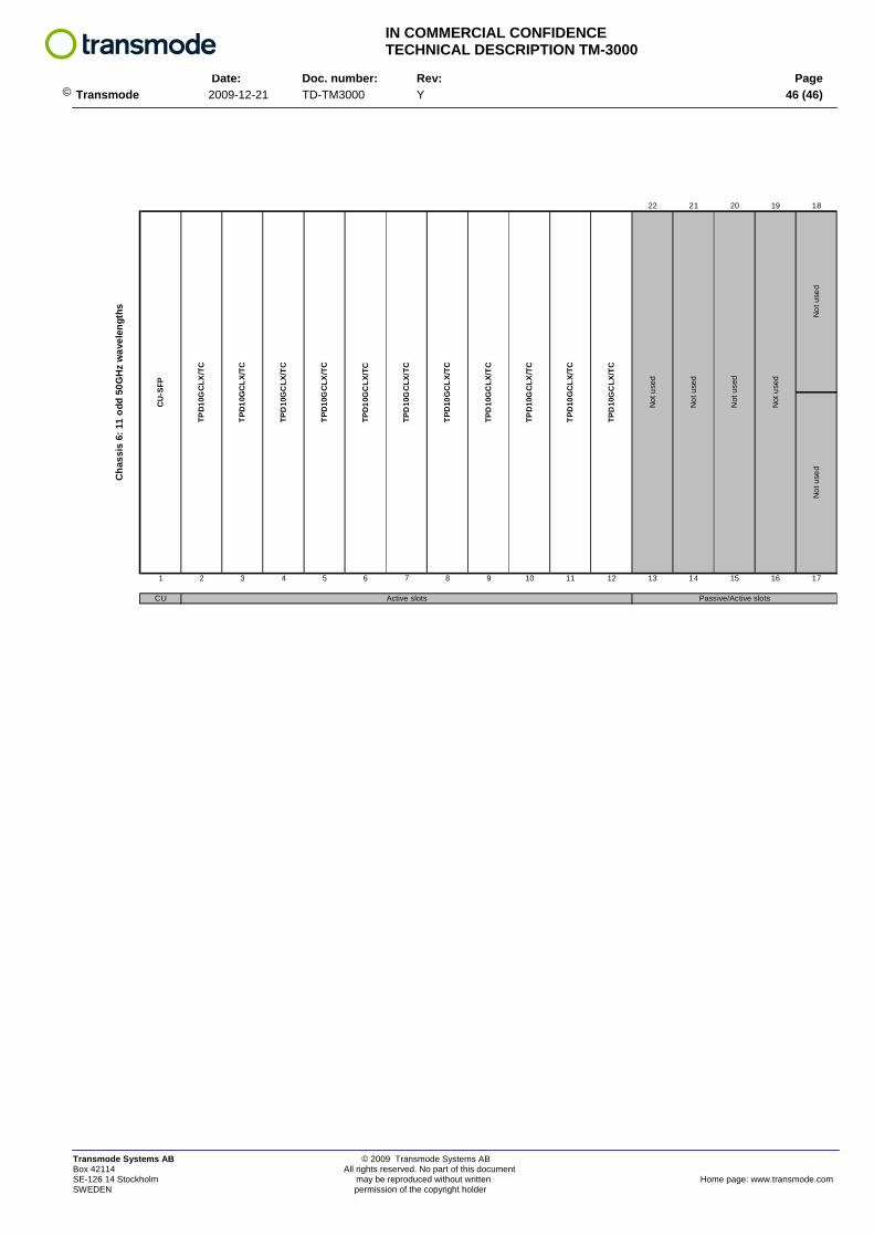
7.7 80ch 50GHz 10G System The 80ch configuration will require usage odd 50GHz channels and consequently tunable Transponders (TP10GCLX/TC or TP10G/TC-ER). The first 40channels are even 50GHz channels and can be provided using Transponders with pluggable optics. In this example the TPD10GBE-BU Transponder is used, i.e. same configuration as for the 40ch example above. Chassis 1 and 2 are thus identical as for the 40ch system. The remaining chassis are different. In total 6 chassis are required to provide an 80ch setup. If e.g. Muxponder units are used there will be one wavelength channel per slot and consequently additional chassis will be required. NOTE! The number of units that can be inserted in a card cage is limited by the total amount of power consumption within the card cage. In the configuration example there are chassis where several slots are unused. This is due to the power consumption restriction.
22 21 20 19 18
1 2 3 4 5 6 7 8 9 10 11 12 13 14 15 16 17
CU Active slots Passive/Active slots
OC
M/2
P
Dou
ble
OA
20 (P
re-a
mp
+ B
oost
er) O
IU-C
-50/
100
OIU
-C-5
0/10
0
Not
use
d
AD
1C-2
F/15
10)
TPD
10G
BE-
BU
TPD
10G
BE
-BU
TPD
10G
BE-
BU
Not
use
d
TPD
10G
BE-
BU
TPD
10G
BE-
BU
TPD
10G
BE-
BU
40ch
MD
U E
VEN
50G
Hz
Cha
ssis
1: 1
6 Ev
en 5
0GH
z w
avel
engt
hs
CU
-SFP
TPD
10G
BE-
BU
TPD
10G
BE
-BU
Transmode Systems AB © 2009 Transmode Systems AB Box 42114 All rights reserved. No part of this document SE-126 14 Stockholm may be reproduced without written Home page: www.transmode.com SWEDEN permission of the copyright holder
IN COMMERCIAL CONFIDENCE TECHNICAL DESCRIPTION TM-3000
Date: Doc. number: Rev: Page
© Transmode 2009-12-21 TD-TM3000 Y 44 (46)
22 21 20 19 18
1 2 3 4 5 6 7 8 9 10 11 12 13 14 15 16 17
CU
Not
use
dN
ot u
sed
Active slots Passive/Active slots
Not
use
d
Not
use
d
Not
use
d
Not
use
d
TPD
10G
BE-
BU
TPD
10G
BE-
BU
Not
use
d
Not
use
d
Cha
ssis
2: 1
8 Ev
en 5
0GH
z w
avel
engt
hs
CU
-SFP
TPD
10G
BE-
BU
TPD
10G
BE
-BU
TPD
10G
BE-
BU
TPD
10G
BE-
BU
TPD
10G
BE-
BU
TPD
10G
BE-
BU
TPD
10G
BE-
BU
22 21 20 19 18
1 2 3 4 5 6 7 8 9 10 11 12 13 14 15 16 17
CU
Not
use
d
Not
use
dN
ot u
sed
Active slots Passive/Active slots
40ch
MD
U O
DD
50G
Hz
TPD
10G
CLX
/TC
TPD
10G
CLX
/TC
TPD
10G
CLX
/TC
Not
use
d
TPD
10G
CLX
/TC
TPD
10G
CLX
/TC
TPD
10G
BE-
BU
TPD
10G
CLX
/TC
TPD
10G
CLX
/TC
Cha
ssis
3: 6
Eve
n 50
GH
z +
7 od
d 50
GH
z w
avel
engt
hs
CU
-SFP
TPD
10G
BE-
BU
TPD
10G
BE
-BU
Transmode Systems AB © 2009 Transmode Systems AB Box 42114 All rights reserved. No part of this document SE-126 14 Stockholm may be reproduced without written Home page: www.transmode.com SWEDEN permission of the copyright holder

IN COMMERCIAL CONFIDENCE TECHNICAL DESCRIPTION TM-3000
Date: Doc. number: Rev: Page
© Transmode 2009-12-21 TD-TM3000 Y 45 (46)
22 21 20 19 18
1 2 3 4 5 6 7 8 9 10 11 12 13 14 15 16 17
CU Active slots Passive/Active slots
TPD
10G
CLX
/TC
TPD
10G
CLX
/TC
TPD
10G
CLX
/TC
Not
use
dN
ot u
sed
Not
use
d
Not
use
d
Not
use
d
TPD
10G
CLX
/TC
TPD
10G
CLX
/TC
TPD
10G
CLX
/TC
Not
use
d
TPD
10G
CLX
/TC
TPD
10G
CLX
/TC
TPD
10G
CLX
/TC
Cha
ssis
4: 1
1 od
d 50
GH
z w
avel
engt
hs
CU
-SFP
TPD
10G
CLX
/TC
TPD
10G
CLX
/TC
22 21 20 19 18
1 2 3 4 5 6 7 8 9 10 11 12 13 14 15 16 17
CU
Not
use
d
Not
use
dN
ot u
sed
Active slots Passive/Active slots
TPD
10G
CLX
/TC
Not
use
d
Not
use
d
Not
use
d
TPD
10G
CLX
/TC
TPD
10G
CLX
/TC
TPD
10G
CLX
/TC
TPD
10G
CLX
/TC
TPD
10G
CLX
/TC
TPD
10G
CLX
/TC
TPD
10G
CLX
/TC
TPD
10G
CLX
/TC
Cha
ssis
5: 1
1 od
d 50
GH
z w
avel
engt
hs
CU
-SFP
TPD
10G
CLX
/TC
TPD
10G
CLX
/TC
Transmode Systems AB © 2009 Transmode Systems AB Box 42114 All rights reserved. No part of this document SE-126 14 Stockholm may be reproduced without written Home page: www.transmode.com SWEDEN permission of the copyright holder
IN COMMERCIAL CONFIDENCE TECHNICAL DESCRIPTION TM-3000
Date: Doc. number: Rev: Page
© Transmode 2009-12-21 TD-TM3000 Y 46 (46)
Transmode Systems AB © 2009 Transmode Systems AB Box 42114 All rights reserved. No part of this document SE-126 14 Stockholm may be reproduced without written Home page: www.transmode.com SWEDEN permission of the copyright holder
22 21 20 19 18
1 2 3 4 5 6 7 8 9 10 11 12 13 14 15 16 17
CU
Not
use
d
Not
use
dN
ot u
sed
Active slots Passive/Active slotsTP
D10
GC
LX/T
C
Not
use
d
Not
use
d
Not
use
d
TPD
10G
CLX
/TC
TPD
10G
CLX
/TC
TPD
10G
CLX
/TC
TPD
10G
CLX
/TC
TPD
10G
CLX
/TC
TPD
10G
CLX
/TC
TPD
10G
CLX
/TC
TPD
10G
CLX
/TC
Cha
ssis
6: 1
1 od
d 50
GH
z w
avel
engt
hs
CU
-SFP
TPD
10G
CLX
/TC
TPD
10G
CLX
/TC