tnc 620 - a tech · pdf filepositioning with the electronic handwheel ... to better...
TRANSCRIPT
TNC 620The Compact Contouring Control for Milling, Drilling and Boring Machines
September 2016
2
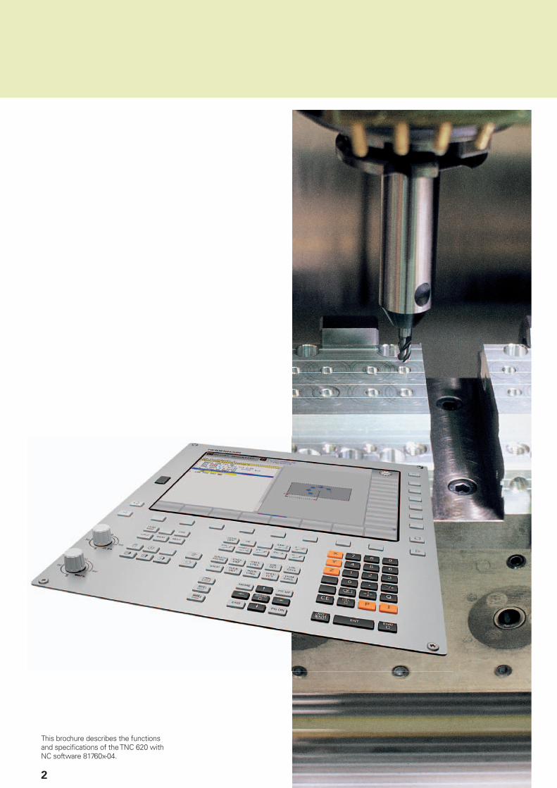
This brochure describes the functions and specifi cations of the TNC 620 with NC software 81760x-04.

3
Contents
The TNC 620... Where can it be used? Compact and versatile
– The right control for milling, drilling and boring machines4
What does it look like? Well designed and user friendly– The TNC 620 in dialog with the user– The functional user interface
6
What can it do? Quick and reliable machining with high contour accuracy– The TNC 620 permits optimum tool movement– Dynamic Precision– Machining any contour slots with trochoidal milling (option)– Active Chatter Control option (ACC)
10
Machining with fi ve axes– Swivel head and rotary table controlled by the TNC 620
16
Minimize setup times– The TNC 620 makes setup easy
18
Automated machining– The TNC 620 measures, manages and communicates
20
How is it programmed? Programming, editing, testing– The TNC 620 opens endless possibilities– Graphic support in any situation
22
Programming in the workshop– Straightforward function keys for complex contours– Programming contours unconventionally– Field-proven cycles for recurring operations– Reusing programmed contour elements– Fast availability of all information
24
Open for communication– The TNC 620 understands CAD fi les– Uniformly digital order management with Connected Machining– The TNC 620 programming station
30
Are there any accessories? Positioning with the electronic handwheel– Delicate axis traverse
35
Workpiece measurement– Setup, presetting and measuring with touch trigger probes
36
Tool measurement– Measuring length, radius and wear directly in the machine
37
Inspecting and optimizing machine accuracy– Calibrating rotary axes with KinematicsOpt
38
... At a glance Overview– Specifi cations, user functions, accessories, options, comparison of controls
39
4
Compact and versatile
– The right control for milling, drilling and boring machines
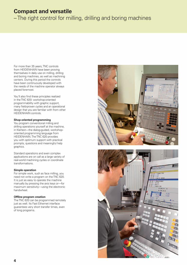
For more than 35 years, TNC controls from HEIDENHAIN have been proving themselves in daily use on milling, drilling and boring machines, as well as machining centers. During this period the controls have been continuously developed with the needs of the machine operator always placed foremost.
You’ll also fi nd these principles realized in the TNC 620: workshop-oriented programmability with graphic support, many fi eld-proven cycles and an operational design that you are familiar with from other HEIDENHAIN controls.
Shop-oriented programming
You program conventional milling and drilling operations yourself at the machine, in Klartext—the dialog-guided, workshop-oriented programming language from HEIDENHAIN. The TNC 620 provides you with optimum support with practical prompts, questions and meaningful help graphics.
Standard operations and even complex applications are on call as a large variety of real-world machining cycles or coordinate transformations.
Simple operation
For simple work, such as face milling, you need not write a program on the TNC 620. It is just as easy to operate the machine manually by pressing the axis keys or—for maximum sensitivity—using the electronic handwheel.
Offl ine program creation
The TNC 620 can be programmed remotely just as well. Its Fast Ethernet interface guarantees very short transfer times, even of long programs.

5
The TNC 620 is compact and easy to
read. The TNC 620 is a compact but versatile contouring control for up to fi ve controlled axes and a controlled spindle. Thanks to its fl exible operation—workshop-oriented programmability with HEIDENHAIN conversational programming or offl ine programming—and its scope of features, it is especially suited for use on universal milling, drilling and boring machines for the following:• Series and single-part production• Tool making• Machine building• Research and development• Prototypes and pilot plants• Repair departments• Training and education facilities
It also offers the applicable features both necessary and helpful for:
Universal milling machines
• Free contour programming• Milling cycles for complex contours• Fast presetting with HEIDENHAIN
touch probes
Drilling and boring machines
• Cycles for drilling, boring and spindle alignment
• Cycles for Cartesian and polar point patterns
• Drilling oblique holes
Five-axis machining with swivel head
and rotary table
• When you are programming away from the machine, the TNC 620 automatically takes the machine geometry into account
• Tilting the working plane• Cylinder surface machining• 3-D tool compensation• Fast execution through short block
processing times
Machines with parallel secondary axes
• Compensating movement in the secondary axes U, V, W through the principal axes X, Y, Z
• Defi ning the principal and secondary axes in the NC program makes it possible to run programs on different machine confi gurations
• Including movements of the parallel axes in the position display of the associated principal axis (sum display)

6
Well designed and user friendly
– The TNC 620 in dialog with the user
The screen
The 15-inch TFT color fl at-panel display shows a clear overview of all relevant information for programming, operating, and inspecting the machine tool and control, such as program blocks, comments and error messages. More information is provided through graphic support during program entry, test run and actual machining.
The selectable “split screen” display shows the part program blocks in one half of the screen and the graphics or the status display in the other half.
During the course of the program, status displays will always offer information to keep you up to date on tool position, the current program, active cycles and coordinate transformations, and other data. The TNC 620 even shows the current machining time.
The keyboard
As with all TNCs from HEIDENHAIN, the operating panel is oriented to the programming process. The well-thought-out arrangement of keys in a clear division into function groups, i.e. programming modes, machining modes, management/TNC functions and navigation, supports you during program input. Simple key assignment and easily understandable symbols or abbreviations clearly indicate each key’s function. You use the override
potentiometers to make delicate adjustments to the feed rate and spindle speed. Like the iTNC 530 and TNC 640—the large
HEIDENHAIN controls—the TNC 620 version with a separate keyboard unit provides additional function units: The alphabetic keypad enables you to easily enter comments and G codes. The integrated machine operating panel features easily exchangeable snap-on keys that allow simple adaptation to the respective machine confi guration. And the operating panel features a complete set of
PC keys and a touchpad.
7
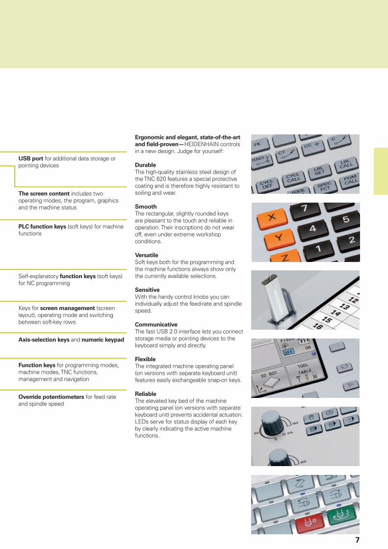
The screen content includes two operating modes, the program, graphics and the machine status
PLC function keys (soft keys) for machine functions
Keys for screen management (screen layout), operating mode and switching between soft-key rows
Self-explanatory function keys (soft keys) for NC programming
USB port for additional data storage or pointing devices
Axis-selection keys and numeric keypad
Override potentiometers for feed rate and spindle speed
Function keys for programming modes, machine modes, TNC functions, management and navigation
Ergonomic and elegant, state-of-the-art
and fi eld-proven—HEIDENHAIN controls in a new design. Judge for yourself:
Durable
The high-quality stainless steel design of the TNC 620 features a special protective coating and is therefore highly resistant to soiling and wear.
Smooth
The rectangular, slightly rounded keys are pleasant to the touch and reliable in operation. Their inscriptions do not wear off, even under extreme workshop conditions.
Versatile
Soft keys both for the programming and the machine functions always show only the currently available selections.
Sensitive
With the handy control knobs you can individually adjust the feed-rate and spindle speed. Communicative
The fast USB 2.0 interface lets you connect storage media or pointing devices to the keyboard simply and directly.
Flexible
The integrated machine operating panel (on versions with separate keyboard unit) features easily exchangeable snap-on keys.
Reliable
The elevated key bed of the machine operating panel (on versions with separate keyboard unit) prevents accidental actuation. LEDs serve for status display of each key by clearly indicating the active machine functions.

8
Well designed and user friendly
– The functional user interface
The combination of the straightforward and ergonomically designed keyboard and the well-designed screen layout are the essence of reliable and fatigue-free operation—principles that HEIDENHAIN has always represented. However, the TNC 620 also offers a number of features that make working with the control even easier and user-friendlier than ever.
Attractive view
The user interface of the TNC 620 has a modern appearance, with slightly rounded forms, color gradients and a homogeneously designed font. The individual screen areas are clearly distinguished and the operating modes are also indicated by their respective symbols.
To better distinguish between the priority of error messages, the TNC 620 displays them in color-coded categories. A color-coded warning triangle is also displayed.
Fast function overview
With smartSelect you enjoy dialog guidance for quick and easy selection of functions that up to now were accessible only through the soft-key structure. As soon as you open smartSelect, it displays a tree structure with all subordinate functions that can be defi ned in the control’s current condition. Moreover, in the right part of the smartSelect window, the TNC displays the integrated help. With the cursor or a mouse click, you immediately access detailed information on the respective function. Also, smartSelect enables you to defi ne fi xed cycles, touch probe cycles, special functions (SPEC FCT), and quickly access the parameter programming.

9
Color-structured programs
The content of a program line can be quite comprehensive: line number, program function, input values, comment. To help you always fi nd your way even in complex programs, the individual program elements on the TNC 620 are shown in different colors. The color syntax highlighting improves your overview when editing NC programs. It enables you to see at a glance, for example, where the editable input values are.
Uniform table editor
Regardless of which table you are editing—whether the tool table, datum table or pallet table—the function and operation of the table editor are always the same.
Info line
In the info line, the TNC 620 shows the respective submode condition and helps you to orient yourself. The function is comparable with the history function in web browsers.
MOD function
The additional mode MOD offers a myriad of possible settings in a standardized layout regardless of the operating mode.
10
Quick and reliable machining with high contour accuracy
– The TNC 620 permits optimum tool movement
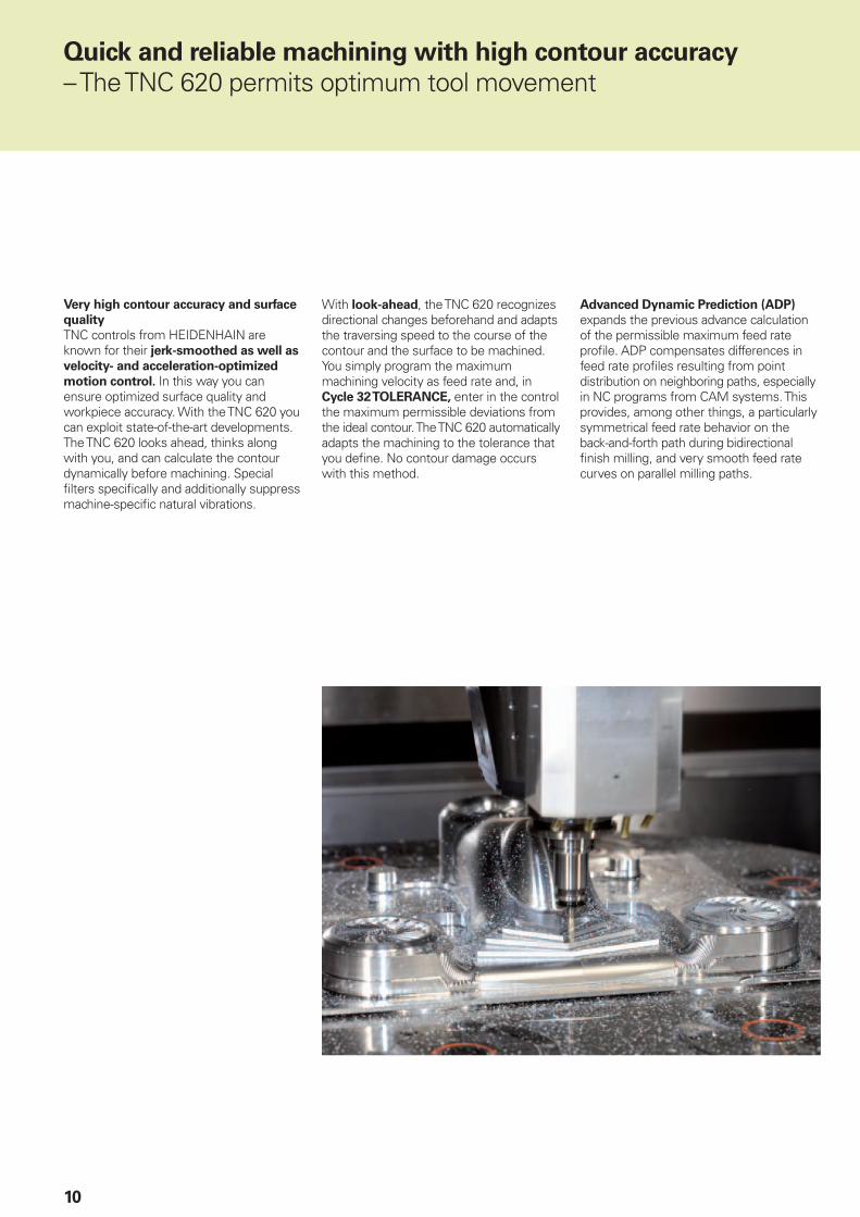
Very high contour accuracy and surface
quality
TNC controls from HEIDENHAIN are known for their jerk-smoothed as well as
velocity- and acceleration-optimized
motion control. In this way you can ensure optimized surface quality and workpiece accuracy. With the TNC 620 you can exploit state-of-the-art developments. The TNC 620 looks ahead, thinks along with you, and can calculate the contour dynamically before machining. Special fi lters specifi cally and additionally suppress machine-specifi c natural vibrations.
With look-ahead, the TNC 620 recognizes directional changes beforehand and adapts the traversing speed to the course of the contour and the surface to be machined. You simply program the maximum machining velocity as feed rate and, in Cycle 32 TOLERANCE, enter in the control the maximum permissible deviations from the ideal contour. The TNC 620 automatically adapts the machining to the tolerance that you defi ne. No contour damage occurs with this method.
Advanced Dynamic Prediction (ADP) expands the previous advance calculation of the permissible maximum feed rate profi le. ADP compensates differences in feed rate profi les resulting from point distribution on neighboring paths, especially in NC programs from CAM systems. This provides, among other things, a particularly symmetrical feed rate behavior on the back-and-forth path during bidirectional fi nish milling, and very smooth feed rate curves on parallel milling paths.

11
Fast machining and computing
processes
The fast block processing time of maximum 1.5 ms enables the TNC 620 to run fast advance calculations in order to optimally use the dynamic parameters of the machine. In this way, functions like ADP and look-ahead not only provide very high contour accuracy and surface defi nition—they also optimize the machining time.
One of the reasons for the TNC 620’s high speed is its uniformly digital control
design. It consists on the one hand of the integrated digital drive technology from HEIDENHAIN, and on the other hand all control components are interconnected with digital interfaces—the control components via HSCI (HEIDENHAIN Serial Controller Interface), and the encoders via EnDat 2.2. This makes it possible to realize very high feed rates. And the TNC 620 interpolates simultaneously in up to fi ve axes. To attain the required cutting speeds, the TNC 620 controls spindle speeds up to 100 000 rpm digitally.
The TNC 620’s powerful 5-axis machining enables you to manufacture even complex 3-D contours. The required programs are usually created on external CAM systems and comprise a large number of very short line segments that are transferred to the control. With its short block processing time, the TNC 620 quickly executes even complex NC programs. Thanks to its computing power, however, it can also transfer complex advance calculations to simpler NC programs. This makes it unimportant what data volume the NC programs from their CAD systems have: with the TNC 620, the fi nished workpiece will be a virtually perfect refl ection of the generated program.

12
The control concept of the TNC 620 guarantees high accuracy and surface defi nition at high machining speeds. These are made possible by differing technologies, cycles and functions. Individually or in combination, they ensure optimized motion control, effective jerk limiting, dynamic contour look-ahead and therefore perfect surfaces with very short machining times.
The hypernym Dynamic Precision stands for a number of HEIDENHAIN solutions for metal cutting that can dramatically improve the dynamic accuracy of a machine tool. It is the result of a new perspective on the competing demand for accuracy, high surface quality and short machining times. The dynamic accuracy of machine tools manifests itself in deviations at the tool center point (TCP). These deviations depend on kinetic quantities such as velocity and acceleration (also jerk), and result, among other things, from the vibrations of machine components.
Quick and reliable machining with high contour accuracy
– Dynamic Precision
13
All the infl uences are together responsible for dimensional inaccuracies and faults in the workpiece surface. They therefore have a decisive infl uence on quality and, when poor-quality parts are scrapped, also on productivity. Dynamic Precision counteracts these problems with intelligent control technology to enable designers to further improve the quality and dynamic perfor-mance of machine tools. That saves time and money in production.
The machine tool builder can use the options comprised by Dynamic Precision either individually or in combination:• CTC – Compensation of position errors
due to machine elasticity between the encoder and the TCP. This increases accuracy during acceleration phases
• AVD – Active vibration damping improves surfaces
• PAC – Position-dependent adaptation of control parameters
• LAC – Load-dependent adaptation of control parameters enhances accuracy regardless of load and aging
• MAC – Motion-dependent adaptation of control parameters
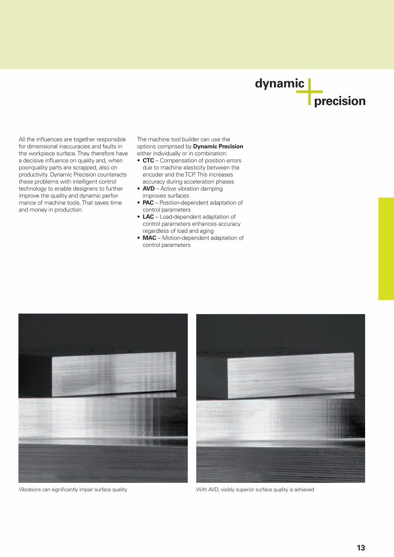
Vibrations can signifi cantly impair surface quality With AVD, visibly superior surface quality is achieved

14
Quick and reliable machining with high contour accuracy
– Machining any contour slots with trochoidal milling (option)
The benefi t of trochoidal milling is its ultra-effi cient machining of slots of all kinds. The roughing process is a circular motion superimposed on a forward linear motion. This procedure is referred to as trochoidal milling. It is used particularly for milling high-strength or hardened materials, where the high loads placed on the tool and machine usually only permit small infeeds.
With trochoidal milling, on the other hand, large cutting depths are possible since the prevailing cutting conditions do not increase the wear and tear on the tool. On the contrary, the entire length of a plain cutter’s cutting edges can be used. This enables you to achieve a greater chip volume per tooth. Circular plunging into the material places less radial force on the tool. This reduces the mechanical load on the machine and prevents vibration.
The slot to be machined is described in a contour subprogram as a contour train. You defi ne the dimensions of the slot and the cutting data in a separate cycle. Any residual material remaining can then easily be removed with a subsequent fi nishing cut.
The benefi ts include:• Engagement of the entire cutter length• Higher chip volume• Relief from mechanical load on the
machine• Less vibration• Integrated fi nishing of the side wall
15
– Active Chatter Control option (ACC)
Strong forces come into play during roughing (power milling). Depending on the tool spindle speed, the resonances in the machine tool, and the chip volume (metal-removal rate during milling), the tool can sometimes begin to “chatter.” This chattering places heavy strain on the machine, and causes ugly marks on the workpiece surface. The tool, too, is subject to heavy and irregular wear from chattering. In extreme cases it can result in tool breakage.
To reduce the inclination to chattering, HEIDENHAIN now offers an effective control function with its Active Chatter Control option (ACC). The use of this control function is particularly advantageous during heavy cutting. ACC makes substantially higher metal removal rates possible. This enables you to increase your metal removal rate by up to 25 % and more, depending on the type of machine. You reduce the mechanical load on the machine and increase the life of your tools at the same time.
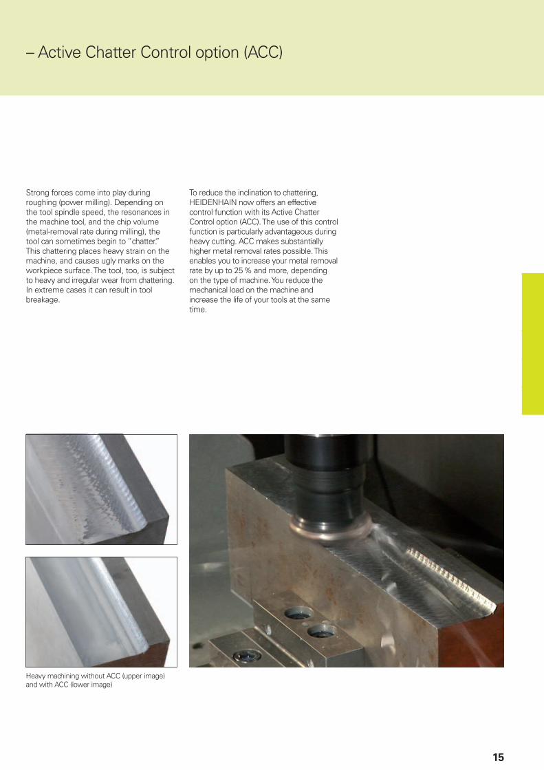
Heavy machining without ACC (upper image) and with ACC (lower image)
16
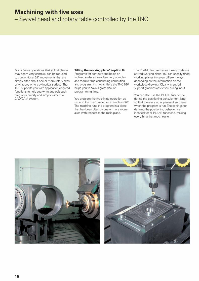
Many 5-axis operations that at fi rst glance may seem very complex can be reduced to conventional 2-D movements that are simply tilted about one or more rotary axes or wrapped onto a cylindrical surface. The TNC supports you with application-oriented functions to help you write and edit such programs quickly and simply without a CAD/CAM system.
Machining with fi ve axes
– Swivel head and rotary table controlled by the TNC
Tilting the working plane* (option 8)
Programs for contours and holes on inclined surfaces are often very complex and require time-consuming computing and programming work. Here the TNC 620 helps you to save a great deal of programming time.
You program the machining operation as usual in the main plane, for example in X/Y. The machine runs the program in a plane that has been tilted by one or more rotary axes with respect to the main plane.
The PLANE feature makes it easy to defi ne a tilted working plane: You can specify tilted working planes in seven different ways, depending on the information on the workpiece drawing. Clearly arranged support graphics assist you during input.
You can also use the PLANE function to defi ne the positioning behavior for tilting so that there are no unpleasant surprises when the program is run. The settings for defi ning the positioning behavior are identical for all PLANE functions, making everything that much easier.
17
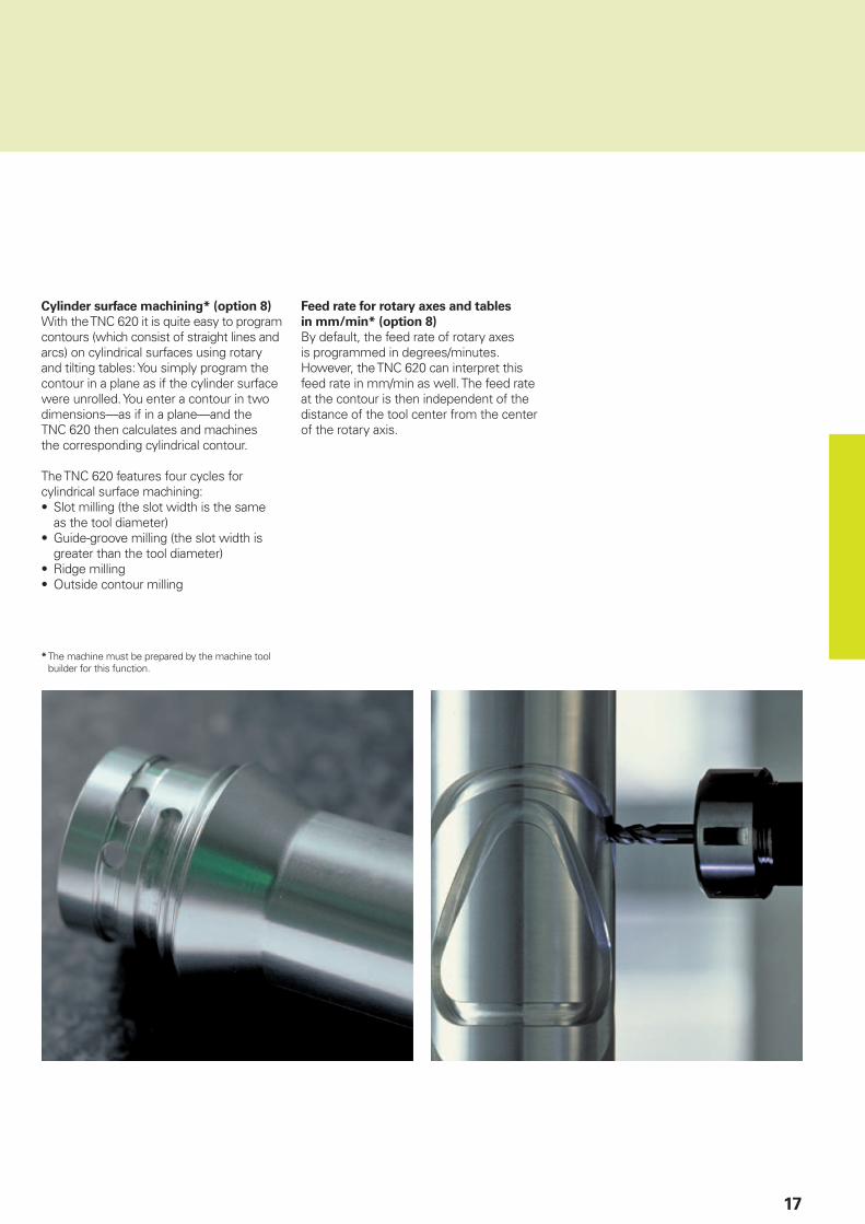
Cylinder surface machining* (option 8)
With the TNC 620 it is quite easy to program contours (which consist of straight lines and arcs) on cylindrical surfaces using rotary and tilting tables: You simply program the contour in a plane as if the cylinder surface were unrolled. You enter a contour in two dimensions—as if in a plane—and the TNC 620 then calculates and machines the corresponding cylindrical contour.
The TNC 620 features four cycles for cylindrical surface machining:• Slot milling (the slot width is the same
as the tool diameter)• Guide-groove milling (the slot width is
greater than the tool diameter)• Ridge milling• Outside contour milling
* The machine must be prepared by the machine tool builder for this function.
Feed rate for rotary axes and tables
in mm/min* (option 8)
By default, the feed rate of rotary axes is programmed in degrees/minutes. However, the TNC 620 can interpret this feed rate in mm/min as well. The feed rate at the contour is then independent of the distance of the tool center from the center of the rotary axis.

18
Minimize setup times
– The TNC 620 makes setup easy
Before you can begin machining, you must fi rst clamp the tool and set up the machine, fi nd the position and orient the workpiece on the machine, and set the workpiece reference point. This is a time-consuming but indispensable procedure. After all, any error directly reduces the machining accuracy. Particularly in small and medium-sized production runs, as well as for very large workpieces, setup times become quite a signifi cant factor.
The TNC 620 features application-oriented, real-world setup functions. They support the user, help to reduce non-productive time, and make overnight, unattended production possible. Together with the touch probes, the TNC 620 offers numerous probing cycles for automatic alignment of the workpieces, presetting, and measurement of the workpiece and the tool.
Delicate manual traverse
For setup, you can use the direction keys to move the machine axes manually or in incremental jog. A simpler and more reliable way, however, is to use the electronic handwheels from HEIDENHAIN (see page 35). With the handwheels you are always close to the action, enjoy a close-up view of the setup process, and can control the infeed responsively and precisely.
Adapting the probing velocity
Frequently, the workpiece has to be probed at hidden locations or in cramped spaces. In this case, the standard probing feed rate is usually too fast. In such situations you can use the override knob to change the feed rate during probing. What is special about this option is that it does not infl uence accuracy.
Workpiece alignment (option 17)
With HEIDENHAIN touch probes (see page 36) and the probing functions of the TNC 620, you can forgo any tedious manual alignment of the workpiece:• Clamp the workpiece in any position.• The touch probe determines the actual
workpiece position by probing a surface, two holes, or two studs.
• The TNC 620 compensates the misalignment with a “basic rotation,” which means that in the NC program the part is rotated by the measured misalignment, or the rotary table itself is turned to correct the misalignment.
Compensating for workpiece
misalignment
by rotating the coordinate system or turning the table
19
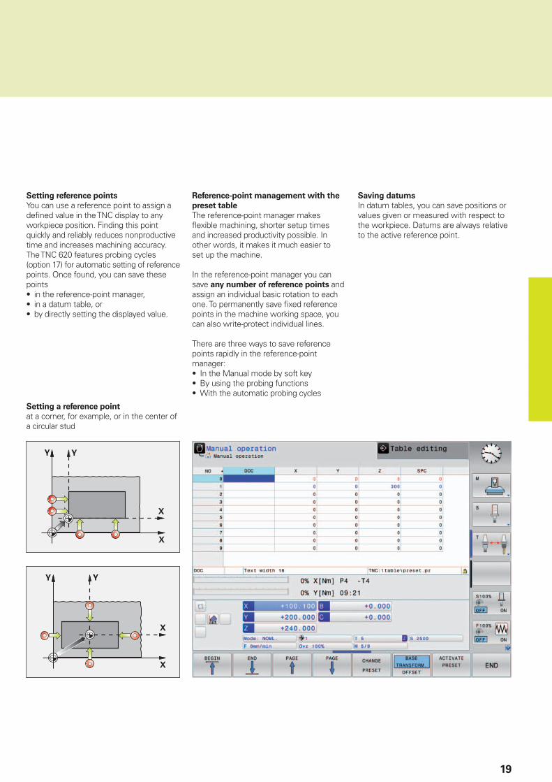
Reference-point management with the
preset table
The reference-point manager makes fl exible machining, shorter setup times and increased productivity possible. In other words, it makes it much easier to set up the machine.
In the reference-point manager you can save any number of reference points and assign an individual basic rotation to each one. To permanently save fi xed reference points in the machine working space, you can also write-protect individual lines.
There are three ways to save reference points rapidly in the reference-point manager:• In the Manual mode by soft key• By using the probing functions• With the automatic probing cycles
Setting reference points
You can use a reference point to assign a defi ned value in the TNC display to any workpiece position. Finding this point quickly and reliably reduces nonproductive time and increases machining accuracy.The TNC 620 features probing cycles (option 17) for automatic setting of reference points. Once found, you can save these points• in the reference-point manager,• in a datum table, or• by directly setting the displayed value.
Setting a reference point
at a corner, for example, or in the center of a circular stud
Saving datums
In datum tables, you can save positions or values given or measured with respect to the workpiece. Datums are always relative to the active reference point.
20
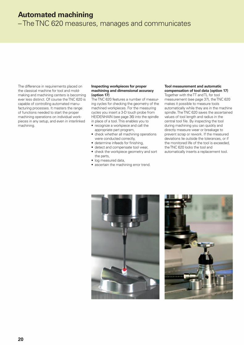
Inspecting workpieces for proper
machining and dimensional accuracy
(option 17)
The TNC 620 features a number of measur-ing cycles for checking the geometry of the machined workpieces. For the measuring cycles you insert a 3-D touch probe from HEIDENHAIN (see page 36) into the spindle in place of a tool. This enables you to• recognize a workpiece and call the
appropriate part program,• check whether all machining operations
were conducted correctly,• determine infeeds for fi nishing,• detect and compensate tool wear,• check the workpiece geometry and sort
the parts,• log measured data,• ascertain the machining error trend.
Automated machining
– The TNC 620 measures, manages and communicates
The difference in requirements placed on the classical machine for tool and mold-making and machining centers is becoming ever less distinct. Of course the TNC 620 is capable of controlling automated manu-facturing processes. It masters the range of functions needed to start the proper machining operations on individual work-pieces in any setup, and even in interlinked machining.
Tool measurement and automatic
compensation of tool data (option 17)
Together with the TT and TL for tool measurement (see page 37), the TNC 620 makes it possible to measure tools automatically while they are in the machine spindle. The TNC 620 saves the ascertained values of tool length and radius in the central tool fi le. By inspecting the tool during machining you can quickly and directly measure wear or breakage to prevent scrap or rework. If the measured deviations lie outside the tolerances, or if the monitored life of the tool is exceeded, the TNC 620 locks the tool and automatically inserts a replacement tool.

21
Pallet management (option 22)
The TNC 620 can assign the appropriate part program and datum shift to parts mounted on pallets and brought to the machine in any sequence. If a pallet is exchanged, the TNC 620 automatically calls the correct part program. This permits automatic machining of a variety of parts in any sequence.
Tool management
For machining centers with automatic tool changers, the TNC 620 offers a central tool memory for any number of tools. The tool memory is a freely confi gurable fi le and can therefore be optimally fi tted to your needs. You can even have the TNC 620 manage your tool names. The control prepares the next tool change while the current tool is still cutting. This signifi cantly reduces the non-cutting time required for changing tools.
With the optionally available extended tool management you can also graphically prepare and display any data.*
* The machine must be prepared by the machine tool builder for this function.
22
Programming, editing, testing
– The TNC 620 opens endless possibilities
The TNC 620 is just as universal in application as it is fl exible in machining and programming.
Positioning with Manual Data Input
You can start working with the TNC 620 even before writing a complete part program. Simply machine a part step by step—switching as you want between manual operation and automatic positioning.
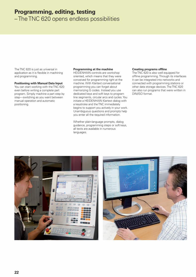
Programming at the machine
HEIDENHAIN controls are workshop oriented, which means that they were conceived for programming right at the machine. With Klartext conversational programming you can forget about memorizing G codes. Instead you use dedicated keys and soft keys to program line segments, circular arcs and cycles. You initiate a HEIDENHAIN Klartext dialog with a keystroke and the TNC immediately begins to support you actively in your work. Unambiguous questions and prompts help you enter all the required information.
Whether plain-language prompts, dialog guidance, programming steps or soft keys, all texts are available in numerous languages.
Creating programs offl ine
The TNC 620 is also well equipped for offl ine programming. Through its interfaces it can be integrated into networks and connected with programming stations or other data storage devices. The TNC 620 can also run programs that were written in DIN/ISO format.
23
– Graphic support in any situation
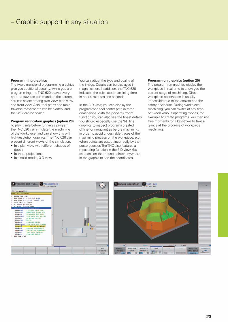
Programming graphics
The two-dimensional programming graphics give you additional security: while you are programming, the TNC 620 draws every entered traverse command on the screen. You can select among plan view, side view, and front view. Also, tool paths and rapid-traverse movements can be hidden, and the view can be scaled.
Program verifi cation graphics (option 20)
To play it safe before running a program, the TNC 620 can simulate the machining of the workpiece, and can show this with high-resolution graphics. The TNC 620 can present different views of the simulation:• In a plan view with different shades of
depth• In three projections• In a solid model, 3-D view
You can adjust the type and quality of the image. Details can be displayed in magnifi cation. In addition, the TNC 620 indicates the calculated machining time in hours, minutes and seconds.
In the 3-D view, you can display the programmed tool-center path in three dimensions. With the powerful zoom function you can also see the fi nest details. You should especially use the 3-D line graphics to inspect programs created offl ine for irregularities before machining, in order to avoid undesirable traces of the machining process on the workpiece, e.g. when points are output incorrectly by the postprocessor. The TNC also features a measuring function in the 3-D view. You can position the mouse pointer anywhere in the graphic to see the coordinates.
Program-run graphics (option 20)
The program-run graphics display the workpiece in real time to show you the current stage of machining. Direct workpiece observation is usually impossible due to the coolant and the safety enclosure. During workpiece machining, you can switch at any time between various operating modes, for example to create programs. You then use free moments for a keystroke to take a glance at the progress of workpiece machining.

24
��
���
��
���
���
Programming in the workshop
– Straightforward function keys for complex contours
Programming 2-D contours
Two-dimensional contours are the bread and butter of the modern machine shop. Here the TNC 620 offers a variety of possibilities.
Programming with path function keys
If contours are dimensioned for NC, which means that the end points are specifi ed in Cartesian or polar coordinates, then you can program them directly with the path function keys.
Straight and circular contour elements
To program a line segment, for example, simply press the key for linear traverse. The TNC 620 asks in plain language for all information required for a complete programming block, such as target coordinates, feed rate, cutter radius compensation and machine functions. Appropriate path function keys for circular movement, chamfers, and corner rounding simplify your programming. To avoid surface blemishes during approach to or departure from the contour, it must be approached smoothly—that is, tangentially.
You simply specify the starting or end point of the contour and the approaching or departing radius of the cutter edge—the control does the rest for you.
The TNC 620 can look ahead over a radius-compensated contour for up to 99 blocks to watch for back cutting and avoid contour damage such as can occur when roughing a contour with a large tool.
Circular path with smooth, (tangential) connection with the preceding contour element, defi ned by end point
Circular path defi ned by its radius, end point and rotational direction
Circular path defi ned by its center, end point, and rotational direction
Corner rounding:
circular path with smooth (tangential) connection on both sides, defi ned by radius and corner point
Straight line defi ned by its end point
Chamfer defi ned by the
corner point and chamfer length

25
FK free contour programming (option 19)
Not all workpieces are dimensioned for conventional NC programming. Thanks to FK, the control’s free contour programming feature, in such cases you simply type in the known data—without fi rst having to convert or calculate your data! It does not matter if individual contour elements are not completely defi ned as long as the complete contour has been. If the given data result in more than one mathematical solution, the helpful TNC 620 programming graphics show you the possible variants for your selection.
– Programming contours unconventionally

26
Programming in the workshop
– Field-proven cycles for recurring operations
Comprehensive fi xed cycles for
milling, drilling and boring
Frequently recurring operations that comprise several working steps are stored in the TNC 620 as cycles. You program them under conversational guidance and are supported by graphics that clearly illustrate the required input parameters.
Standard cycles
Besides the fi xed cycles for drilling and tapping (with or without fl oating tap holder), there are optional cycles (option 19) for thread milling, reaming, boring and for hole patterns, as well as milling cycles for clearing plane surfaces, and for roughing and fi nishing pockets, slots and studs.
Cycles for complex contours (option 19)
The Subcontour List cycles (SL) are particularly helpful for clearing pockets with combined contours. This term is used to identify machining cycles for pilot drilling, roughing and fi nishing when the contour or subcontours are specifi ed in subroutines. In this way, one contour description can be used for more than one operation using different tools.
Up to twelve subcontours can be superimposed for machining. The control automatically calculates the resulting contour and the tool paths for roughing or clearing the surfaces. Subcontours can be pockets or islands. Different components are combined to form a single pocket in which the tool avoids the islands.
The TNC 620 maintains a fi nishing
allowance on the wall and fl oor surfaces during roughing. When roughing with different tools, the control identifi es material remaining in inside corners so that it can be cleared later with smaller tools. A separate cycle is used for milling to the fi nished dimension.
27
OEM cycles (option 19)
As original equipment manufacturers (OEMs), machine tool builders can contribute their special manufacturing know-how by designing additional fi xed cycles and saving them in the TNC 620. However, the end user can write his own cycles as well. HEIDENHAIN makes this possible with its PC program CycleDesign. This enables you to organize the input parameters and soft-key structure of the TNC 620 to suit your own needs.
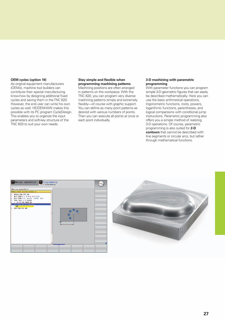
Stay simple and fl exible when
programming machining patterns
Machining positions are often arranged in patterns on the workpiece. With the TNC 620, you can program very diverse machining patterns simply and extremely fl exibly—of course with graphic support. You can defi ne as many point patterns as desired with various numbers of points. Then you can execute all points at once or each point individually.
3-D machining with parametric
programming
With parameter functions you can program simple 3-D geometric fi gures that can easily be described mathematically. Here you can use the basic arithmetical operations, trigonometric functions, roots, powers, logarithmic functions, parentheses, and logical comparisons with conditional jump instructions. Parametric programming also offers you a simple method of realizing 3-D operations. Of course, parametric programming is also suited for 2-D
contours that cannot be described with line segments or circular arcs, but rather through mathematical functions.
28
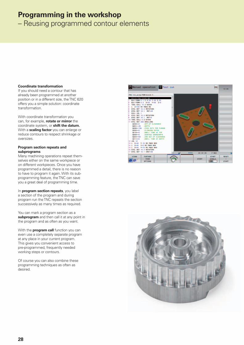
Coordinate transformation
If you should need a contour that has already been programmed at another position or in a different size, the TNC 620 offers you a simple solution: coordinate transformation.
With coordinate transformation you can, for example, rotate or mirror the coordinate system, or shift the datum. With a scaling factor you can enlarge or reduce contours to respect shrinkage or oversizes.
Program section repeats and
subprograms
Many machining operations repeat them-selves either on the same workpiece or on different workpieces. Once you have programmed a detail, there is no reason to have to program it again. With its sub-programming feature, the TNC can save you a great deal of programming time.
In program section repeats, you label a section of the program and during program run the TNC repeats the section successively as many times as required.
You can mark a program section as a subprogram and then call it at any point in the program and as often as you want.
With the program call function you can even use a completely separate program at any place in your current program. This gives you convenient access to pre-programmed, frequently needed working steps or contours.
Of course you can also combine these programming techniques as often as desired.
Programming in the workshop
– Reusing programmed contour elements
29
– Fast availability of all information
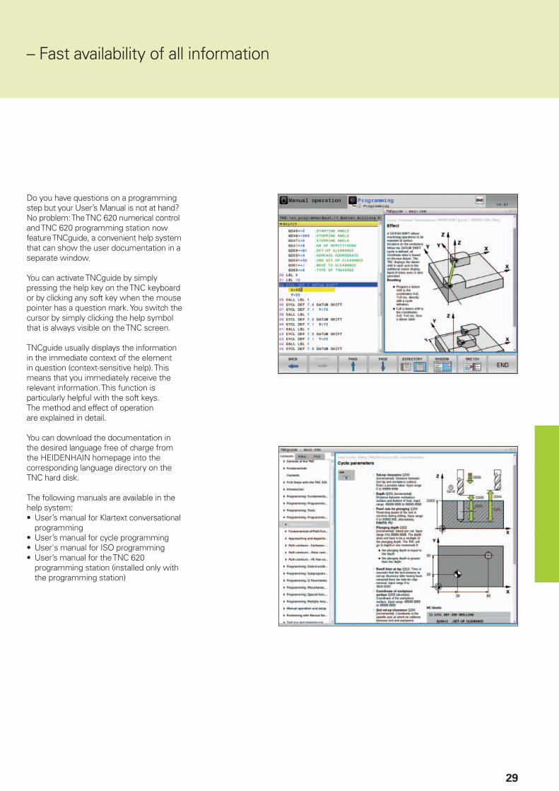
Do you have questions on a programming step but your User’s Manual is not at hand? No problem: The TNC 620 numerical control and TNC 620 programming station now feature TNCguide, a convenient help system that can show the user documentation in a separate window.
You can activate TNCguide by simply pressing the help key on the TNC keyboard or by clicking any soft key when the mouse pointer has a question mark. You switch the cursor by simply clicking the help symbol that is always visible on the TNC screen.
TNCguide usually displays the information in the immediate context of the element in question (context-sensitive help). This means that you immediately receive the relevant information. This function is particularly helpful with the soft keys. The method and effect of operation are explained in detail.
You can download the documentation in the desired language free of charge from the HEIDENHAIN homepage into the corresponding language directory on the TNC hard disk.
The following manuals are available in the help system:• User’s manual for Klartext conversational
programming• User’s manual for cycle programming• User's manual for ISO programming• User’s manual for the TNC 620
programming station (installed only with the programming station)
30
Open for communication
– The TNC 620 understands CAD fi les
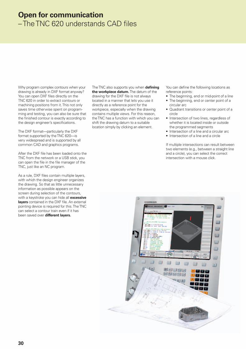
Why program complex contours when your drawing is already in DXF format anyway? You can open DXF fi les directly on the TNC 620 in order to extract contours or machining positions from it. This not only saves time otherwise spent on program-ming and testing, you can also be sure that the fi nished contour is exactly according to the design engineer’s specifi cations.
The DXF format—particularly the DXF format supported by the TNC 620—is very widespread and is supported by all common CAD and graphics programs.
After the DXF fi le has been loaded onto the TNC from the network or a USB stick, you can open the fi le in the fi le manager of the TNC, just like an NC program.
As a rule, DXF fi les contain multiple layers, with which the design engineer organizes the drawing. So that as little unnecessary information as possible appears on the screen during selection of the contours, with a keystroke you can hide all excessive
layers contained in the DXF fi le. An external pointing device is required for this. The TNC can select a contour train even if it has been saved over different layers.
The TNC also supports you when defi ning
the workpiece datum. The datum of the drawing for the DXF fi le is not always located in a manner that lets you use it directly as a reference point for the workpiece, especially when the drawing contains multiple views. For this reason, the TNC has a function with which you can shift the drawing datum to a suitable location simply by clicking an element.
You can defi ne the following locations as reference points:• The beginning, end or mid-point of a line• The beginning, end or center point of a
circular arc• Quadrant transitions or center point of a
circle• Intersection of two lines, regardless of
whether it is located inside or outside the programmed segments
• Intersection of a line and a circular arc• Intersection of a line and a circle
If multiple intersections can result between two elements (e.g., between a straight line and a circle), you can select the correct intersection with a mouse click.
31
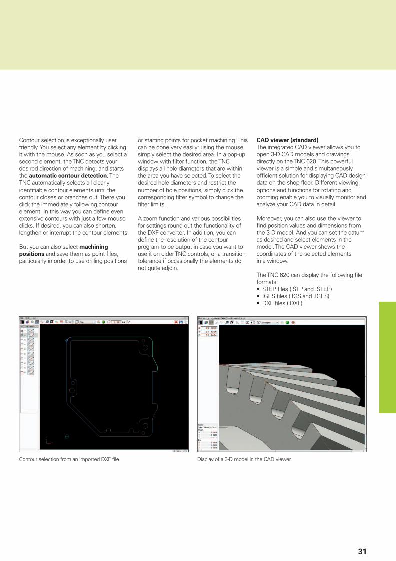
Contour selection from an imported DXF fi le
Contour selection is exceptionally user friendly. You select any element by clicking it with the mouse. As soon as you select a second element, the TNC detects your desired direction of machining, and starts the automatic contour detection. The TNC automatically selects all clearly identifi able contour elements until the contour closes or branches out. There you click the immediately following contour element. In this way you can defi ne even extensive contours with just a few mouse clicks. If desired, you can also shorten, lengthen or interrupt the contour elements.
But you can also select machining
positions and save them as point fi les, particularly in order to use drilling positions
or starting points for pocket machining. This can be done very easily: using the mouse, simply select the desired area. In a pop-up window with fi lter function, the TNC displays all hole diameters that are within the area you have selected. To select the desired hole diameters and restrict the number of hole positions, simply click the corresponding fi lter symbol to change the fi lter limits.
A zoom function and various possibilities for settings round out the functionality of the DXF converter. In addition, you can defi ne the resolution of the contour program to be output in case you want to use it on older TNC controls, or a transition tolerance if occasionally the elements do not quite adjoin.
Display of a 3-D model in the CAD viewer
CAD viewer (standard)
The integrated CAD viewer allows you to open 3-D CAD models and drawings directly on the TNC 620. This powerful viewer is a simple and simultaneously effi cient solution for displaying CAD design data on the shop fl oor. Different viewing options and functions for rotating and zooming enable you to visually monitor and analyze your CAD data in detail.
Moreover, you can also use the viewer to fi nd position values and dimensions from the 3-D model. And you can set the datum as desired and select elements in the model. The CAD viewer shows the coordinates of the selected elements in a window.
The TNC 620 can display the following fi le formats:• STEP fi les (.STP and .STEP)• IGES fi les (.IGS and .IGES)• DXF fi les (.DXF)

32
Company network
Programming
system
TNC 320
Ethernet interface
TNC 620
Ethernet interface
iTNC 530
Ethernet interface
Open for communication
– Uniformly digital order management with Connected Machining
The well functioning transfer of knowledge contributes decisively to the success of any company. To transfer knowledge quickly and without loss, effective communication via e-mail is just as much a matter of course as the universal availability of electronic production documents or the transfer of data to merchandise management systems and production activity control systems. The tools and raw materials in stock, tool data, fi xture setups, CAD data, NC programs, and inspection instructions must be available to machine operators across all shifts. Eco-nomic manufacturing therefore demands an effi ciently working process chain and a numeric control connected to this network.
The TNC 620, with its Connected Machin-
ing package of functions, integrates itself fl exibly into your process chain and helps you to optimize the transfer of knowledge
within your company. So also grant your workshop all the information available in your company. Connected Machining makes uniformly digital order management possible in networked manufacturing. You thus profi t from:• Easy data usage• Time-saving procedures• Transparent processes
The networked TNC 620
By integrating the TNC 620 with its Connected Machining functions in your company network, the control connects the workshop with PCs, programming stations, and other data storage devices in other areas of your company:• Design• Programming• Simulation• Production planning• Production
Even in its standard version, the TNC 620 features a latest-generation Gigabit Ethernet interface in addition to its RS-232-C/V.24 data interface. The TNC 620 communicates with NFS servers and Windows networks in TCP/IP protocol without needing additional software. The fast data transfer at rates of up to 1000 Mbps guarantees very short transfer times. The TNC 620 offers the best technological conditions for Connected
Machining, the networking of the control in the workshop with all areas of your company that accompany production.

33
k
++CAM
ERP
PPS
CAD
TNC 620 IPC
Documents
Standard performance range
In order to be able to use the data that you have transmitted to the control via the standard network connections, the TNC 620 offers you several interesting applications, even as part of the standard scope of functions. A CAD viewer, PDF viewer oder the web browser Mozilla Firefox make the simplest form of Connected Machining possible: access to manufacturing process data right at the control.
The operation of web-based documentation software or ERP systems is just as possible here as is access to your e-mail inbox. The following fi le formats can also be opened directly on the TNC:• Text fi les ending with .txt or .ini• Graphic fi les ending with .gif, .bmp, .jpg,
or .png• Table fi les ending with .xls or .csv• HTML fi les
Data transfer with Connected Machining
An additional solution for uniformly digital order management as part of Connected
Machining is the free TNCremo software for PCs. With it, and even over the Ethernet interface, you can• transfer remotely stored part programs
and tool or pallet tables in both directions, and
• start the machine.With the powerful TNCremoPlus software for PCs you can also transfer the screen contents of the control to your PC using the live-screen function.
Using order-related data on the control
With the REMOTE DESKTOP MANAGER (option 133) you operate a Windows PC directly from the TNC 620. You can access IT systems of the process chain directly from the control, and you also profi t from much more effi cient setup procedures by eliminating tedious journeys between the machine and the offi ce. Technical drawings, CAD data, NC programs, tool data, work instructions, parts lists and warehouse information are digitally available at the machine. E-mails can be sent and received very easily. With a simple keystroke on the machine operating panel you can switch between the control screen and the screen of the Windows PC. It can be a computer in the local network or an industrial PC in the machine’s electrical cabinet.
With the IPC 6641, HEIDENHAIN offers an industrial PC with very high computing power and the newest processor architec-ture for installation in an electrical cabinet. This enables you to easily and effi ciently solve even the most computationally intensive tasks in CAD/CAM on your TNC control.
Detailed data for an optimal
organization of the production process
HEIDENHAIN DNC* has several functions, including the connection of TNC controls to merchandise management systems and production activity control systems. For example, this interface can be used for the confi guration of automatic feedback messages about active production pro-cesses. This increases transparency in manufacturing even with a batch size of one and supports timely order manage-ment.
With the TNC 620 and Connected
Machining, uniformly digital order management becomes surprisingly simple. Optimize your processes and use the full innovative potential of your workshop.
* The machine must be prepared by the machine tool builder for this function.
34
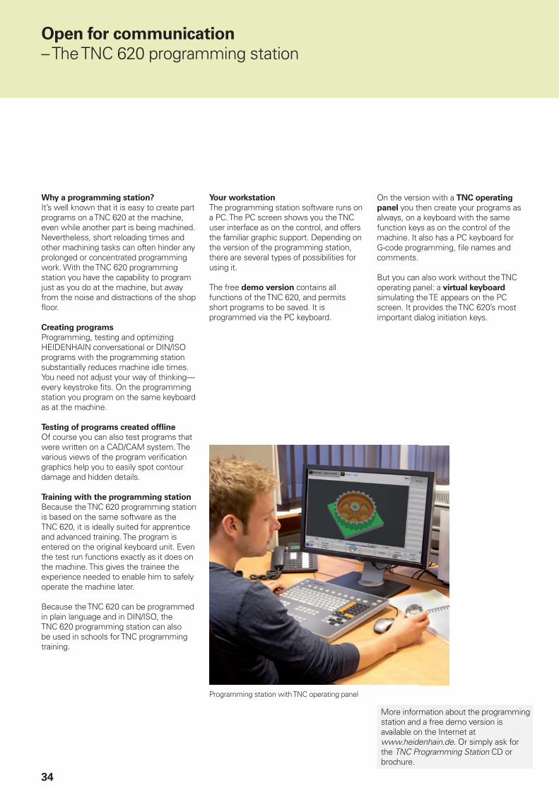
Programming station with TNC operating panel
Why a programming station?
It’s well known that it is easy to create part programs on a TNC 620 at the machine, even while another part is being machined. Nevertheless, short reloading times and other machining tasks can often hinder any prolonged or concentrated programming work. With the TNC 620 programming station you have the capability to program just as you do at the machine, but away from the noise and distractions of the shop fl oor.
Creating programs
Programming, testing and optimizing HEIDENHAIN conversational or DIN/ISO programs with the programming station substantially reduces machine idle times. You need not adjust your way of thinking—every keystroke fi ts. On the programming station you program on the same keyboard as at the machine.
Testing of programs created offl ine
Of course you can also test programs that were written on a CAD/CAM system. The various views of the program verifi cation graphics help you to easily spot contour damage and hidden details.
Training with the programming station
Because the TNC 620 programming station is based on the same software as the TNC 620, it is ideally suited for apprentice and advanced training. The program is entered on the original keyboard unit. Even the test run functions exactly as it does on the machine. This gives the trainee the experience needed to enable him to safely operate the machine later.
Because the TNC 620 can be programmed in plain language and in DIN/ISO, the TNC 620 programming station can also be used in schools for TNC programming training.
Your workstation
The programming station software runs on a PC. The PC screen shows you the TNC user interface as on the control, and offers the familiar graphic support. Depending on the version of the programming station, there are several types of possibilities for using it.
The free demo version contains all functions of the TNC 620, and permits short programs to be saved. It is programmed via the PC keyboard.
On the version with a TNC operating
panel you then create your programs as always, on a keyboard with the same function keys as on the control of the machine. It also has a PC keyboard for G-code programming, fi le names and comments.
But you can also work without the TNC operating panel: a virtual keyboard simulating the TE appears on the PC screen. It provides the TNC 620’s most important dialog initiation keys.
Open for communication
– The TNC 620 programming station
More information about the programming station and a free demo version is available on the Internet at www.heidenhain.de. Or simply ask for the TNC Programming Station CD or brochure.

35
HR 550
Positioning with the electronic handwheel
– Delicate axis traverse
To set up the workpiece you can use the direction keys to move the machine axes manually. A simpler and more sensitive way, however, is to use the electronic handwheels from HEIDENHAIN.
You can move the axis slide through the feed motors in direct relation to the rotation of the handwheel. For delicate operations you can set the transmission ratio to certain preset distances per handwheel revolution.
Panel-mounted handwheels
The HR 130 and HR 150 panel-mounted handwheels from HEIDENHAIN can be integrated in the machine operating panel or mounted at another location on the machine. An adapter permits connection of up to three HR 150 electronic panel-mounted handwheels.
The following functions are available on the HR 520 and HR 550 handwheels:
• Traverse distance per revolution can be set
• Display for operating mode, actual position value, programmed feed rate and spindle speed, error messages
• Override potentiometer for feed rate and spindle speed
• Selection of axes via keys or soft keys• Keys for continuous traverse of the axes• Emergency stop button• Actual position capture• NC start/stop• Spindle on/off• Soft keys for machine functions defi ned
by the machine tool builder
Portable handwheels
The HR 510, HR 520 and HR 550 portable handwheels are particularly helpful for when you have to work close to the machine’s working space. The axis keys and certain functional keys are integrated in the housing. In this way you can switch axes and set up the machine at any time—regardless of where you happen to be standing. The HR 520 and HR 550 hand-wheels feature an integrated display for user-friendly remote operation of the control. As a wireless handwheel, the HR 550 is ideal for use on large machine tools. If you no longer need the handwheel, just attach it to the machine somewhere by its built-in magnets.
36
SE 660
TS 460
Workpiece measurement
– Setup, presetting and measuring with touch trigger probes
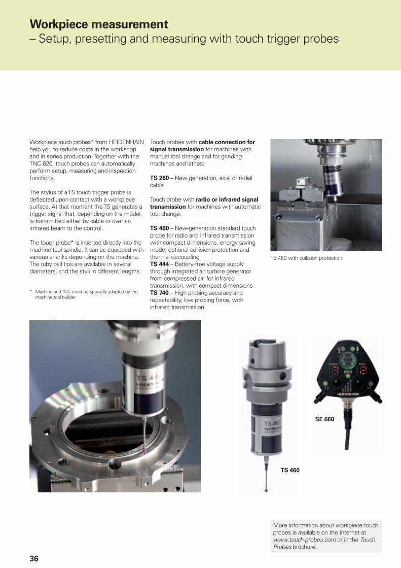
Workpiece touch probes* from HEIDENHAIN help you to reduce costs in the workshop and in series production: Together with the TNC 620, touch probes can automatically perform setup, measuring and inspection functions.
The stylus of a TS touch trigger probe is defl ected upon contact with a workpiece surface. At that moment the TS generates a trigger signal that, depending on the model, is transmitted either by cable or over an infrared beam to the control.
The touch probe* is inserted directly into the machine tool spindle. It can be equipped with various shanks depending on the machine. The ruby ball tips are available in several diameters, and the styli in different lengths.
* Machine and TNC must be specially adapted by the machine tool builder.
Touch probes with cable connection for
signal transmission for machines with manual tool change and for grinding machines and lathes:
TS 260 – New generation, axial or radial cable
Touch probe with radio or infrared signal
transmission for machines with automatic tool change:
TS 460 – New-generation standard touch probe for radio and infrared transmission with compact dimensions, energy-saving mode, optional collision protection and thermal decouplingTS 444 – Battery-free voltage supply through integrated air turbine generator from compressed air, for infrared transmission, with compact dimensionsTS 740 – High probing accuracy and repeatability, low probing force, with infrared transmission
More information about workpiece touch probes is available on the Internet at www.touch-probes.com or in the Touch Probes brochure.
TS 460 with collision protection

37
TL Micro
TT 460
Tool measurement
– Measuring length, radius and wear directly in the machine
The tool is of course a decisive factor in ensuring a consistently high level of production quality. This means that an exact measurement of the tool dimensions and periodic inspection of the tool for wear and breakage, as well as the shape of each tooth, are necessary. HEIDENHAIN offers the TT trigger tool touch probes as well as the non-contacting TL Nano and TL Micro laser systems for tool measurement.
The systems are installed directly in the machine’s workspace, where they permit tool measurement either before machining or during interruptions.
The TT tool touch probes measure the tool length and radius. When probing the rotating or stationary tool, e.g. during individual tooth measurement, the contact plate is defl ected and a trigger signal is transmitted directly to the TNC 620.
The TT 160 uses signal transmission by cable, whereas the TT 460 operates with wireless signal transmission over radio or an infrared beam. It is therefore particularly suitable for use on rotary and tilting tables.
The TL Nano and TL Micro laser systems are available for various maximum tool diameters. Using a laser beam, they probe the tool without contact, and can detect form errors of individual teeth along with the tool length and radius.
More information about tool touch probes is available on the Internet at www.touch-probes.com or in the Touch Probes brochure.
38
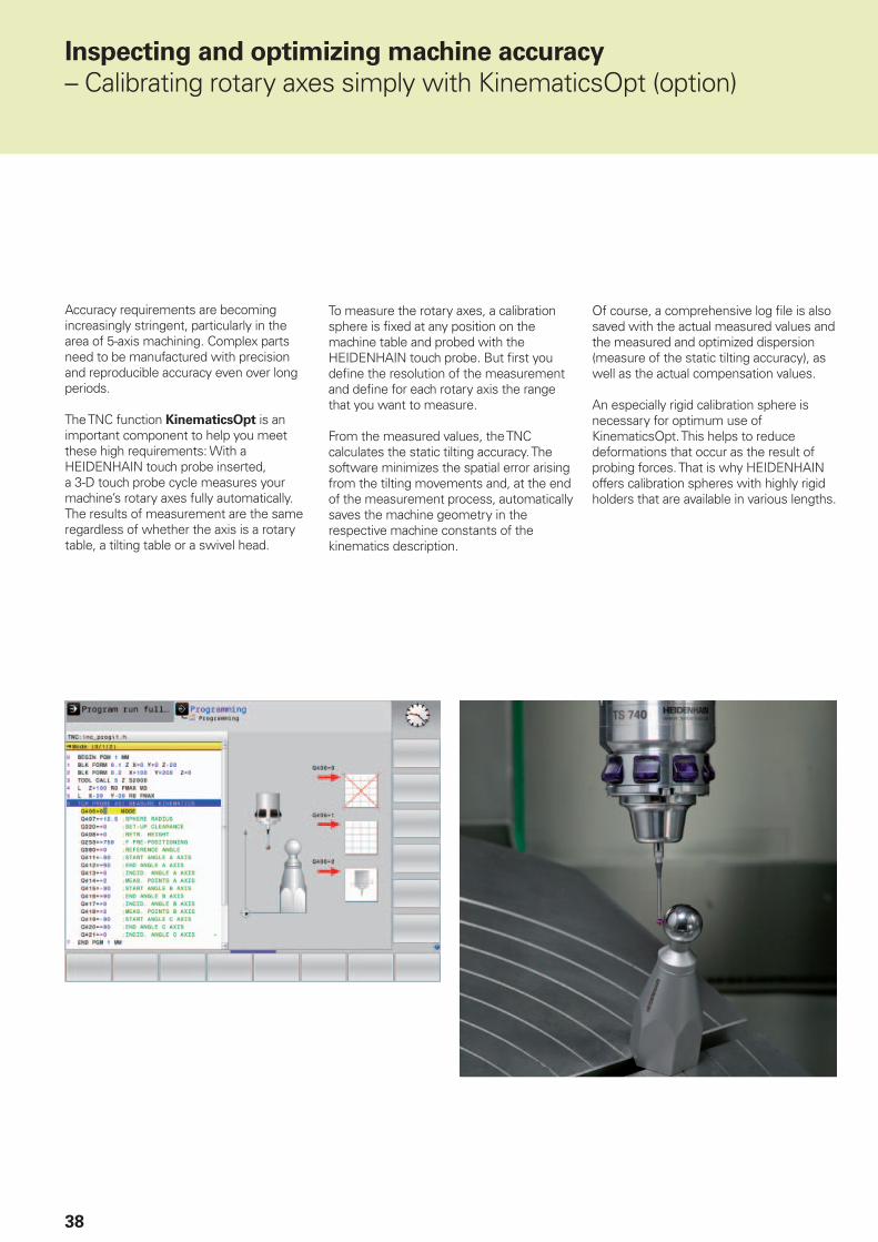
Accuracy requirements are becoming increasingly stringent, particularly in the area of 5-axis machining. Complex parts need to be manufactured with precision and reproducible accuracy even over long periods.
The TNC function KinematicsOpt is an important component to help you meet these high requirements: With a HEIDENHAIN touch probe inserted, a 3-D touch probe cycle measures your machine’s rotary axes fully automatically. The results of measurement are the same regardless of whether the axis is a rotary table, a tilting table or a swivel head.
Inspecting and optimizing machine accuracy
– Calibrating rotary axes simply with KinematicsOpt (option)
To measure the rotary axes, a calibration sphere is fi xed at any position on the machine table and probed with the HEIDENHAIN touch probe. But fi rst you defi ne the resolution of the measurement and defi ne for each rotary axis the range that you want to measure.
From the measured values, the TNC calculates the static tilting accuracy. The software minimizes the spatial error arising from the tilting movements and, at the end of the measurement process, automatically saves the machine geometry in the respective machine constants of the kinematics description.
Of course, a comprehensive log fi le is also saved with the actual measured values and the measured and optimized dispersion (measure of the static tilting accuracy), as well as the actual compensation values.
An especially rigid calibration sphere is necessary for optimum use of KinematicsOpt. This helps to reduce deformations that occur as the result of probing forces. That is why HEIDENHAIN offers calibration spheres with highly rigid holders that are available in various lengths.

39
Overview
– Specifi cations
Specifi cations
Sta
nd
ard
Op
tio
n
Components • MC main computer with operating panel and integrated 15.1-inch TFT color fl at-panel displayorMC main computer with separate TE 730 or TE 735 operating panel and integrated 15.1-inch TFT
color fl at panel display
Operating system • HEROS 5 real-time operating system for machine control
Memory • 1.8 GB (on CFR compact fl ash memory card) for NC programs
Input resolution and
display step
••
2323
Linear axes: to 0.1 µmRotary axes: to 0.0001°Linear axes: to 0.01 µmRotary axes: to 0.000 01°
Input range • Maximum 999 999 999 mm or 999 999 999°
Interpolation •
•
•
9
8
Linear in 4 axesLinear in 5 axes (subject to export permit)Circular in 2 axesCircular in 3 axes with tilted working planeHelical: superimposition of circular and straight paths
Block processing time • 1.5 ms (3-D straight line without radius compensation)
Axis feedback control •
•Position loop resolution: Signal period of the position encoder/1024Cycle time of interpolator: 3 ms
Range of traverse • Maximum 100 m
Spindle speed • Maximum 60 000 rpm (with 2 pole pairs)
Error compensation •
•
Linear and nonlinear axis error, backlash, reversal peaks during circular movements, thermal expansion
Static friction, sliding friction, reversal error
Data interfaces •
•
••
18
RS-232-C/V.24 max. 115 kbpsExtended data interface with LSV-2 protocol for remote operation of the TNC 620 over the data
interface with the HEIDENHAIN software TNCremo or TNCremoPlusGigabit Ethernet interface 1000BASE-T5 x USB (1 x front USB 2.0; 4 x back panel USB 3.0)HEIDENHAIN-DNC for communication between a Windows application and TNC (DCOM
interface)
Diagnostics • Fast and simple troubleshooting through integrated diagnostic aids
Ambient temperature ••
Operation: +5 °C to +45 °CStorage: –35 °C to +65 °C

40
Overview
– User functions
User functions
Sta
nd
ard
Op
tio
n
Short description •
•0/1
Basic version: 3 axes plus spindleOne or two additional NC axesDigital current and shaft speed control
Program entry ••
42
HEIDENHAIN Klartext conversationalISO ( with integrated operating panel: via soft keys or external standard USB keyboard;
with separate operating panel: via ASCII keyboard)Direct loading of contours or machining positions from DXF fi les and saving as Klartext
conversational contouring program or as point table
Position information •••
Nominal positions for lines and arcs in Cartesian coordinates or polar coordinatesIncremental or absolute dimensionsDisplay and entry in mm or inches
Tool compensation •
219
Tool radius in the working plane and tool lengthRadius compensated contour look ahead for up to 99 blocks (M120)Three-dimensional tool-radius compensation for changing tool data without having to recalculate
an existing program
Tool tables • Multiple tool tables with any number of tools
Cutting data • Automatic calculation of spindle speed, cutting speed, feed per tooth and feed per revolution
Constant contour speed ••
Relative to the path of the tool centerRelative to the tool’s cutting edge
Parallel operation • Creating a program with graphical support while another program is being run
3-D machining •9999
Motion control with highly smoothed jerk3-D tool compensation through surface normal vectorsKeeping the tool normal to the contourTool radius compensation normal to the tool directionManual traverse in the active tool-axis system
Machining with a
rotary table
88
Programming of cylindrical contours as if in two axesFeed rate in distance per minute
Contour elements •••••••
Straight lineChamferCircular pathCircle centerCircle radiusTangentially connecting circular arcCorner rounding
Approaching and
departing the contour
••
Via straight line: tangential or perpendicularVia circular arc
FK free contour
programming
19 FK free contour programming in HEIDENHAIN conversational format with graphic support for workpiece drawings not dimensioned for NC
Program jumps •••
SubprogramsProgram section repeatsCalling any program as a subprogram
41
User functions
Sta
nd
ard
Op
tio
n
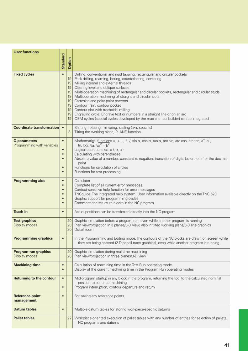
Fixed cycles •19191919191919191919
Drilling, conventional and rigid tapping, rectangular and circular pocketsPeck drilling, reaming, boring, counterboring, centeringMilling internal and external threadsClearing level and oblique surfacesMulti-operation machining of rectangular and circular pockets, rectangular and circular studsMultioperation machining of straight and circular slotsCartesian and polar point patternsContour train, contour pocketContour slot with trochoidal millingEngraving cycle: Engrave text or numbers in a straight line or on an arcOEM cycles (special cycles developed by the machine tool builder) can be integrated
Coordinate transformation •8
Shifting, rotating, mirroring, scaling (axis specifi c)Tilting the working plane, PLANE function
Q parameters
Programming with variables•
•••
••
Mathematical functions =, +, –, *, /, sin , cos , tan , arc sin, arc cos, arc tan, an, en, In, log, a, a2 + b2
Logical operations (=, = /, <, >)Calculating with parenthesesAbsolute value of a number, constant , negation, truncation of digits before or after the decimal
pointFunctions for calculation of circlesFunctions for text processing
Programming aids ••••••
CalculatorComplete list of all current error messagesContext-sensitive help function for error messagesTNCguide: The integrated help system. User information available directly on the TNC 620Graphic support for programming cyclesComment and structure blocks in the NC program
Teach-In • Actual positions can be transferred directly into the NC program
Test graphics
Display modes202020
Graphic simulation before a program run, even while another program is runningPlan view/projection in 3 planes/3-D view, also in tilted working plane/3-D line graphicsDetail zoom
Programming graphics • In the Programming and Editing mode, the contours of the NC blocks are drawn on screen while they are being entered (2-D pencil-trace graphics), even while another program is running
Program-run graphics
Display modes2020
Graphic simulation during real-time machiningPlan view/projection in three planes/3-D view
Machining time ••
Calculation of machining time in the Test Run operating modeDisplay of the current machining time in the Program Run operating modes
Returning to the contour •
•
Mid-program startup in any block in the program, returning the tool to the calculated nominal position to continue machining
Program interruption, contour departure and return
Reference-point
management
• For saving any reference points
Datum tables • Multiple datum tables for storing workpiece-specifi c datums
Pallet tables 22 Workpiece-oriented execution of pallet tables with any number of entries for selection of pallets, NC programs and datums
42
User functions
Sta
nd
ard
Op
tio
n
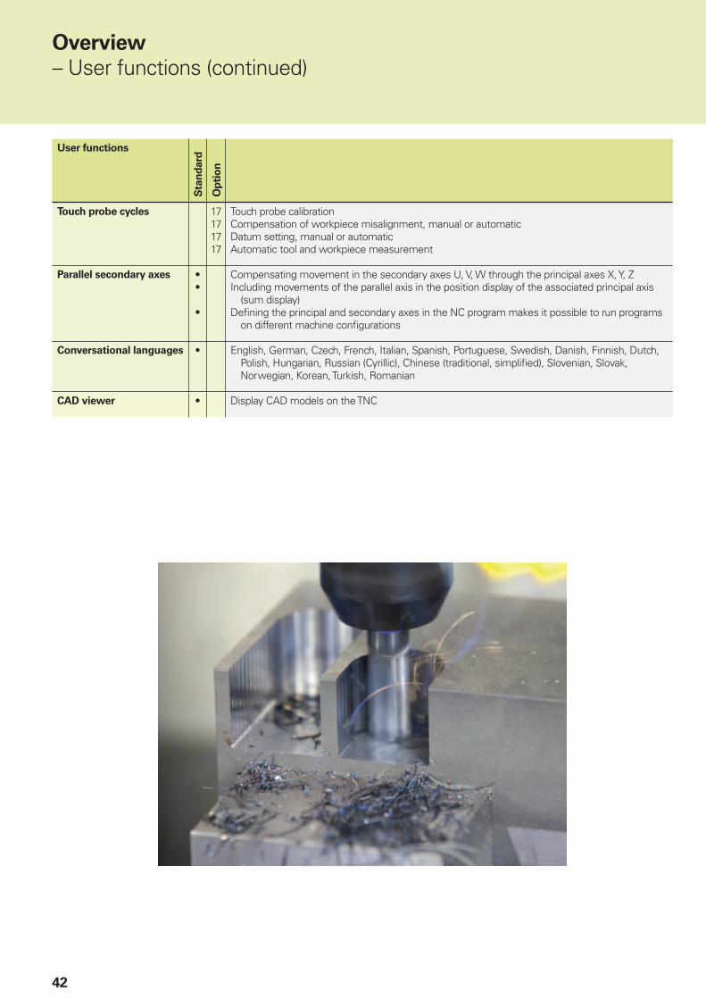
Touch probe cycles 17171717
Touch probe calibrationCompensation of workpiece misalignment, manual or automaticDatum setting, manual or automaticAutomatic tool and workpiece measurement
Parallel secondary axes ••
•
Compensating movement in the secondary axes U, V, W through the principal axes X, Y, ZIncluding movements of the parallel axis in the position display of the associated principal axis
(sum display)Defi ning the principal and secondary axes in the NC program makes it possible to run programs
on different machine confi gurations
Conversational languages • English, German, Czech, French, Italian, Spanish, Portuguese, Swedish, Danish, Finnish, Dutch, Polish, Hungarian, Russian (Cyrillic), Chinese (traditional, simplifi ed), Slovenian, Slovak, Norwegian, Korean, Turkish, Romanian
CAD viewer • Display CAD models on the TNC
Overview
– User functions (continued)
43
Accessories
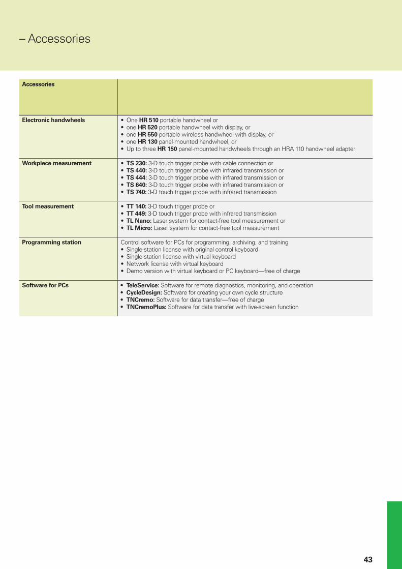
Electronic handwheels • One HR 510 portable handwheel or• one HR 520 portable handwheel with display, or• one HR 550 portable wireless handwheel with display, or• one HR 130 panel-mounted handwheel, or• Up to three HR 150 panel-mounted handwheels through an HRA 110 handwheel adapter
Workpiece measurement • TS 230: 3-D touch trigger probe with cable connection or• TS 440: 3-D touch trigger probe with infrared transmission or• TS 444: 3-D touch trigger probe with infrared transmission or• TS 640: 3-D touch trigger probe with infrared transmission or• TS 740: 3-D touch trigger probe with infrared transmission
Tool measurement • TT 140: 3-D touch trigger probe or• TT 449: 3-D touch trigger probe with infrared transmission• TL Nano: Laser system for contact-free tool measurement or• TL Micro: Laser system for contact-free tool measurement
Programming station Control software for PCs for programming, archiving, and training• Single-station license with original control keyboard• Single-station license with virtual keyboard• Network license with virtual keyboard• Demo version with virtual keyboard or PC keyboard—free of charge
Software for PCs • TeleService: Software for remote diagnostics, monitoring, and operation• CycleDesign: Software for creating your own cycle structure• TNCremo: Software for data transfer—free of charge• TNCremoPlus: Software for data transfer with live-screen function
– Accessories
44
Overview
– Options
Option
number
Option As of NC
software
81776x-
ID Comment
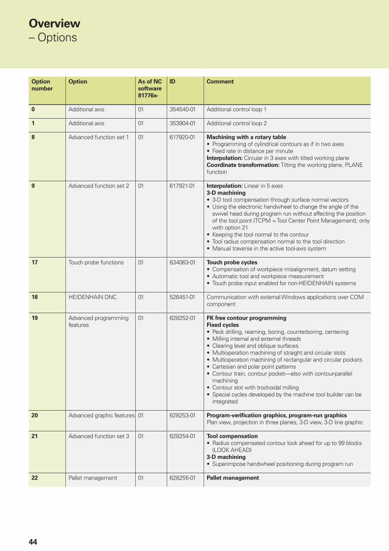
0 Additional axis 01 354540-01 Additional control loop 1
1 Additional axis 01 353904-01 Additional control loop 2
8 Advanced function set 1 01 617920-01 Machining with a rotary table
• Programming of cylindrical contours as if in two axes• Feed rate in distance per minuteInterpolation: Circular in 3 axes with tilted working planeCoordinate transformation: Tilting the working plane, PLANE function
9 Advanced function set 2 01 617921-01 Interpolation: Linear in 5 axes3-D machining
• 3-D tool compensation through surface normal vectors• Using the electronic handwheel to change the angle of the
swivel head during program run without affecting the position of the tool point (TCPM = Tool Center Point Management); only with option 21
• Keeping the tool normal to the contour• Tool radius compensation normal to the tool direction• Manual traverse in the active tool-axis system
17 Touch probe functions 01 634063-01 Touch probe cycles
• Compensation of workpiece misalignment, datum setting• Automatic tool and workpiece measurement• Touch probe input enabled for non-HEIDENHAIN systems
18 HEIDENHAIN DNC 01 526451-01 Communication with external Windows applications over COM component
19 Advanced programming features
01 628252-01 FK free contour programming
Fixed cycles
• Peck drilling, reaming, boring, counterboring, centering• Milling internal and external threads• Clearing level and oblique surfaces• Multioperation machining of straight and circular slots• Multioperation machining of rectangular and circular pockets• Cartesian and polar point patterns• Contour train, contour pocket—also with contour-parallel
machining• Contour slot with trochoidal milling• Special cycles developed by the machine tool builder can be
integrated
20 Advanced graphic features 01 628253-01 Program-verifi cation graphics, program-run graphics
Plan view, projection in three planes, 3-D view, 3-D line graphic
21 Advanced function set 3 01 628254-01 Tool compensation
• Radius compensated contour look ahead for up to 99 blocks (LOOK AHEAD)
3-D machining
• Superimpose handwheel positioning during program run
22 Pallet management 01 628255-01 Pallet management

45
Option
number
Option As of NC
software
81776x-
ID Comment
23 Display step 01 632986-01 Display step to 0.01 µm or 0.000 01°
24 Gantry axes 01 634621-01 Gantry axes in master-slave torque control
42 DXF converter 01 526450-01 Load and convert DXF contours
46 Python OEM process 01 579650-01 Python application on the TNC
48 KinematicsOpt 01 630916-01 Touch-probe cycles for automatic measurement of rotary axes
49 Double speed 01 632223-01 Short control-loop cycle times for direct drives
93 Extended tool management
01 676938-01 Extended tool management
133 Remote Desk. Manager 01 894423-01 Display and remote operation of external computer units (e.g. a Windows PC)
141 Cross Talk Comp. 01 800542-01 CTC: Compensation of axis couplings
142 Pos. Adapt. Control 01 800544-01 PAC: Position-dependent adaptation of the control parameters
143 Load Adapt. Control 01 800545-01 LAC: Load-dependent adaptation of the control parameters
144 Motion Adapt. Control 01 800546-01 MAC: Motion-dependent adaptation of control parameters
145 Active chatter control 01 800547-01 ACC: Active suppression of chatter
146 Active vibration damping 01 800548-01 AVD: Active suppression of vibration

46
Overview
– Comparison of controls
Comparison of controls TNC 620NC SW 81760x-04
TNC 640NC SW 34059x-07
iTNC 530NC SW 60642x-04
Area of application Standard milling High-end
milling/turning
High-end milling
• Simple machining centers (up to 5 axes + 1 spindle)
• Machine tools/machining centers (up to 18 axes + 2 spindles) –
• Milling/turning operations (up to 18 axes + 2 spindles) – Option –
Program entry
• HEIDENHAIN Klartext conversational
• According to ISO
• DXF converter Option Option Option
• CAD viewer Option
• FK free contour programming Option
• Extended milling and drilling cycles Option
• Turning cycles – Option –
NC program memory 1.8 GB > 21 GB > 21 GB
5-axis and high-speed machining Option Option Option
Block processing time 1.5 ms 0.5 ms 0.5 ms
Input resolution and display step (standard/option) 0.1 µm/0.01 µm 0.1 µm/0.01 µm 0.1 µm/–
New design of the screen and keyboard 15-inch screen 15/19-inch screen 15/19-inch screen
Optimized user interface –
Adaptive feed control (AFC) – Option Option
Active chatter control (ACC) Option Option Option
Dynamic collision monitoring (DCM) – Option Option
KinematicsOpt Option Option Option
KinematicsComp – Option Option
Touch probe cycles Option
Pallet management Option
Parallel axis function –
Standard– Not available


PL APS02-384 Warszawa, Polandwww.heidenhain.pl
PT FARRESA ELECTRÓNICA, LDA.4470 - 177 Maia, Portugalwww.farresa.pt
RO HEIDENHAIN Reprezentanta RomaniaBrasov, 500407, Romaniawww.heidenhain.ro
RS Serbia BG
RU OOO HEIDENHAIN115172 Moscow, Russiawww.heidenhain.ru
SE HEIDENHAIN Scandinavia AB12739 Skärholmen, Swedenwww.heidenhain.se
SG HEIDENHAIN PACIFIC PTE LTD.Singapore 408593www.heidenhain.com.sg
SK KOPRETINA TN s.r.o.91101 Trencin, Slovakiawww.kopretina.sk
SL NAVO d.o.o.2000 Maribor, Sloveniawww.heidenhain.si
TH HEIDENHAIN (THAILAND) LTDBangkok 10250, Thailandwww.heidenhain.co.th
TR T&M Mühendislik San. ve Tic. LTD. STI·.
34775 Y. Dudullu – Ümraniye-Istanbul, Turkeywww.heidenhain.com.tr
TW HEIDENHAIN Co., Ltd.Taichung 40768, Taiwan R.O.C.www.heidenhain.com.tw
UA Gertner Service GmbH Büro Kiev 01133 Kiev, Ukrainewww.heidenhain.ua
US HEIDENHAIN CORPORATIONSchaumburg, IL 60173-5337, USAwww.heidenhain.com
VE Maquinaria Diekmann S.A. Caracas, 1040-A, VenezuelaE-mail: [email protected]
VN AMS Co. LtdHCM City, VietnamE-mail: [email protected]
ZA MAFEMA SALES SERVICES C.C.Midrand 1685, South Africawww.heidenhain.co.za
ES FARRESA ELECTRONICA S.A.08028 Barcelona, Spainwww.farresa.es
FI HEIDENHAIN Scandinavia AB01740 Vantaa, Finlandwww.heidenhain.fi
FR HEIDENHAIN FRANCE sarl92310 Sèvres, Francewww.heidenhain.fr
GB HEIDENHAIN (G.B.) LimitedBurgess Hill RH15 9RD, United Kingdomwww.heidenhain.co.uk
GR MB Milionis Vassilis17341 Athens, Greecewww.heidenhain.gr
HK HEIDENHAIN LTDKowloon, Hong KongE-mail: [email protected]
HR Croatia SL
HU HEIDENHAIN Kereskedelmi Képviselet1239 Budapest, Hungarywww.heidenhain.hu
ID PT Servitama Era ToolsindoJakarta 13930, IndonesiaE-mail: [email protected]
IL NEUMO VARGUS MARKETING LTD.Tel Aviv 61570, IsraelE-mail: [email protected]
IN HEIDENHAIN Optics & ElectronicsIndia Private LimitedChetpet, Chennai 600 031, Indiawww.heidenhain.in
IT HEIDENHAIN ITALIANA S.r.l.20128 Milano, Italywww.heidenhain.it
JP HEIDENHAIN K.K.Tokyo 102-0083, Japanwww.heidenhain.co.jp
KR HEIDENHAIN Korea LTD.Gasan-Dong, Seoul, Korea 153-782www.heidenhain.co.kr
MX HEIDENHAIN CORPORATION MEXICO20290 Aguascalientes, AGS., MexicoE-mail: [email protected]
MY ISOSERVE SDN. BHD.43200 Balakong, SelangorE-mail: [email protected]
NL HEIDENHAIN NEDERLAND B.V.6716 BM Ede, Netherlandswww.heidenhain.nl
NO HEIDENHAIN Scandinavia AB7300 Orkanger, Norwaywww.heidenhain.no
PH Machinebanks` CorporationQuezon City, Philippines 1113E-mail: [email protected]
AR NAKASE SRL.B1653AOX Villa Ballester, Argentinawww.heidenhain.com.ar
AT HEIDENHAIN Techn. Büro Österreich83301 Traunreut, Germanywww.heidenhain.de
AU FCR Motion Technology Pty. LtdLaverton North 3026, AustraliaE-mail: [email protected]
BE HEIDENHAIN NV/SA1760 Roosdaal, Belgiumwww.heidenhain.be
BG ESD Bulgaria Ltd.Sofi a 1172, Bulgariawww.esd.bg
BR DIADUR Indústria e Comércio Ltda.04763-070 – São Paulo – SP, Brazilwww.heidenhain.com.br
BY GERTNER Service GmbH220026 Minsk, Belaruswww.heidenhain.by
CA HEIDENHAIN CORPORATIONMississauga, OntarioL5T2N2, Canadawww.heidenhain.com
CH HEIDENHAIN (SCHWEIZ) AG8603 Schwerzenbach, Switzerlandwww.heidenhain.ch
CN DR. JOHANNES HEIDENHAIN (CHINA) Co., Ltd.Beijing 101312, Chinawww.heidenhain.com.cn
CZ HEIDENHAIN s.r.o.102 00 Praha 10, Czech Republicwww.heidenhain.cz
DK TP TEKNIK A/S2670 Greve, Denmarkwww.tp-gruppen.dk
DE HEIDENHAIN Vertrieb Deutschland83301 Traunreut, Deutschland 08669 31-3132 08669 32-3132E-Mail: [email protected]
HEIDENHAIN Technisches Büro Nord12681 Berlin, Deutschland 030 54705-240
HEIDENHAIN Technisches Büro Mitte07751 Jena, Deutschland 03641 4728-250
HEIDENHAIN Technisches Büro West44379 Dortmund, Deutschland 0231 618083-0
HEIDENHAIN Technisches Büro Südwest70771 Leinfelden-Echterdingen, Deutschland 0711 993395-0
HEIDENHAIN Technisches Büro Südost83301 Traunreut, Deutschland 08669 31-1345
Vollständige und weitere Adressen siehe www.heidenhain.deFor complete and further addresses see www.heidenhain.de
������������ ��� ��������������� ��������������������������������������� �������������� �������������������� !��"�#����������
������ !���� ��!�
Zu
m A
bh
eft
en
hie
r fa
lzen
! /
Fo
ld h
ere
fo
r fi
lin
g!
896140-26 · 7.5 · 9/2016 · F&W · Printed in Germany