to - defense technical information center · dre = fa and erf = «t . let the lateral dii-tance of...
TRANSCRIPT

UNCLASSIFIED
AD NUMBER
CLASSIFICATION CHANGESTO:FROM:
LIMITATION CHANGESTO:
FROM:
AUTHORITY
THIS PAGE IS UNCLASSIFIED
ADA800665
unclassified
secret
Approved for public release; distribution isunlimited.
Distribution authorized to DoD only; ForeignGovernment Information; MAY 1945. Otherrequests shall be referred to British Embassy,3100 Massachusetts Avenue, NW, Washington, DC20008.
DSTL, AVIA 26/882, 7 Aug 2009; DSTL, AVIA26/882, 7 Aug 2009

Reproduction Quality Notice
This document is part of the Air Technical Index [ATI] collection. The ATI collection is over 50 years old and was imaged from roll film. The collection has deteriorated over time and is in poor condition. DTIC has reproduced the best available copy utilizing the most current imaging technology. ATI documents that are partially legible have been included in the DTIC collection due to their historical value.
If you are dissatisfied with this document, please feel free to contact our Directorate of User Services at [703] 767-9066/9068 or DSN 427-9066/9068.
Do Not Return This Document To DTIC

Reproduced by
AIR DOCUMENTS DIVISION
HEADQUARTERS AIR MATERIEL COMMAND
WRIGHT FIELD. DAYTON, OHIO

I A
I

3'JiÜB—f L' v *
COPY No. at
SECRET
T.R.E. REPOR & JOOU
V
f ._..c;._ i o.
(Attention is called to the penalties attaching to any infraction of the Official Secrets Act.)
This document is the property of H.M. Government.
It is intended for the use of the recipient only, and for communication to such officers under him as may require to be acquainted with the contents of the report in the course of their duties. The Officers exercising this power of communication will be held responsible that such information is imparted with due caution and reserve.
Any person other than the authorised holder, upon obtaining possession of this document by finding or otherwise, should forward it, together with his name and address, in a closed envelope to The Secretary, Ministry of Aircraft Production, Church House, Westminster, S.W.I. Letter postage need not be prepaid, other postage will be refunded.
All persons are hereby warned that the unauthorised retention or destruction of this document is an offence against the Official Secrets Acts 1911—1920.
<t (12/«) 8193 Wt. 15088—1647 10,000 6/« G.S.SI. Gp. 620
i' s) r T v. C u II L. f ,U1T R

T.R.ü. gjjggcaa! TIüMJ.
SECRET /sLECrOiCVX SHIÜUTOR ^JiD PIiOK)33) CONTROL SYSTEM
STOffiiARY
Long Shot is tho oodo name for an air-launched rocket. The weapon is designed primarily to be launchc1. fron a fighter aeroplane and to be autamatioally guided towards an onuny aircraft. The type of control described in this paper is designed ior a lino of sight trajectory in which tho rocket is controlled to fly down the axis of a radio beam which is kept pointed at the target. In order to investigate the stability and performance of various types of control system an electrical simulator was built, the function of the simulator being to produce voltages proportional to the movoncnt of the rocket after the application of the controlling rudders. Thu aerodynamic characteristics of the rocket and the way in which they are simulated are described.
A control system has been evolved v/hich gives a satiafactary performance on the simulator. ^ theoretical description of this system is given and its performance on the simulator is also described.
INTRODUCTION
Before describing the simulator it is necessary to describe the aerodynamic characteristics of the rocket which it is required to simulate,
xMa ia dealt with in Section 1, for which the information has been supplied by 3^. Section 2 describes the simulator designed for these aerodynarj c characteristics. Section 3 gives a theoretical description of tho typo ci' control system v/hich is at present proposed for controlling the rookot, St ction k gives on account or tho results of the initial tests of thia central system using the simulator described in Section 2. Appendix I .;ivo;j a list of the symbols U3cd in describing tho aerodynamic charactoristico d the rocket.
i. AEKOpmiygc CTJ/J^CTERISTICS as? TUB ROCKET
It ia proposed that the rocket will only be controlled after the propulsion has ceased, the duration of the burning being of tho order of 1 to lg- seconds. Thus during the control period the velocity will be approximately constant and will be of the order of 1500 ft. per
second. In fig. (i) PA is a fixed datum line, PB is tho line of sight, R is the position of tho rocket, RE is itt. heading and RP is the direction in which tho centre of gravity of the rocket is moving. CD is a lino through R parallel to the flctum line PA. Lot DRF = V , DRE = fa and ERF = «t . Let the lateral dii-tance of R from the datum be ho and from the line of sight bo h. Lot hi = YIQ - h be the lateral distance of the line of sight from the Odium. Lot ''be the velocity of the centre of gravity of the rocket. Then assuming that <A , 0 and fare small angles the following relation."- .".pply:-
01 • 0 - * 1.1 h a ho • hj_ 1.2 *»'• 7 »in f m Wr^ 1.3 dt
Now the lift on the v/ings will be proportional to the angle incidence <X, and honco the lateral acceleration d2^ will be pro;
to tK; this may conveniently be written in the form
at > % d2ho 1.4 V at2"
where Jfcjj is ;. constant with the dimensions of time.
Prom 1»3 a^'-i 1*4 WO have
d. • K, a* 1.5 x "eft
\
of proportional
i
W ^
TV-L

and fror, 1,1 and 1.5 1.6
It will be soon that this ocj.ur.tion defines the relation between the heading of the rocket and the path of the C.G., i.e. it defines the amount cf yaw.
It is proposed that the wing ayatom -..ill be designed so that_ during the control period the rocket has neutral weathercock stability. The controls will consist of ui.iall j-rJ-rs cf 'bang-bang' rudders, i.e. the rudders will be cither hard ov.„* one way or hard over the other. Thus the effect of the rudäers will be to apply constant torque to the rocket about its centre of gravity which will in turn produce a constant angular acceleration of the rocket heading. Thus if this acceleration is Q radians/sec2 we have
d^ at2
± 9 1.7
Differentiating 1.6 twice and substituting in 1.7 we have 2 3
at* a»y = + 1.8
3 •+, or fron 1.3 d^hp + 1^ dTip n + QV = - P —- 1.9 d?" dt2*-
where P = Qir is a constant with dimensions of ft/sco^.
EFFECT OF ggjBJBBBSI 3B6BBBB JD :;0TAR1* S&ME3B Suppose the centre cf pressure cf the wings and body is not exactly
conincident with the centre of gravity of the rocket. Then the lift force will epply r. torque about the C.G. which may oppose or assist the __iy torque duo to the rudders, depending on whether
ay oppo3i the C.P. is behind or
in front cf the C.G., i.e. whether the weathercock stability is positive or negative. Since fror. 1.5 the lift is proportional to dfi equation 1.7 will now become "3F"
S. dt it
— 1.7a
where K2 i3 a constant with dimensions of (time)"l whose value depends on the distance between the C.G. rnd tho C.P., being positive if the C.P. is behind the C.G. and negative if it is in front.
The effect of rotary drxping is to epply a torque about the C.G. of the rocket proportional to the angular velocity of the rotation about the C.G., i.e. proportional to ä6. Thiü torque Will oppose the torque
due to the rudders.
a2 43 dtz
Thus oqaation 1.7 beoonoi
t 9 - K- at
- 1.7b
where of
1.7c
re KT is a constant v/ith dimensions of (time)" In the presence both rotary damping and weathercock stability equation 1.7 becomes
dt dt Z IT If we substitute for p7 frori 1.6 we have
" ^. at 2...
d2* +K, a^v dt3 dt
•iQ + % d2y\ - K, d*v 1mi 2dT (Ko + K,) ajü + (1 + K,K,) £j¥ + K. a^ = + Q
J at x ' . öF" 17Tfc3~ 1.10
/or from

-3-
orfrcnl.* (K2 + K3) d^ + (l + KK) d3ho + K ^ = + p ... dt*
1.11 at->
For the design of the simulator the f dlovdng values were assumed for constants, these values hc.ijj.ng been calculated by R.US for the proposed design of Long Shot.
Q = 7 radians/sec2 V a 1500 f t/sec Kj«? second.
These figures arc only tentative at pre»ent, in particular consideration is being given to the use of rudders giving a larger valuo of angular acceleration Q. However they will be used in this report to give an indication of the orders of magnitude involved in the design of the simulator and control system.
In order to investigate the tolerance allowed on the distance between the C.P. and C.G., the constant K2 has been varied between 0 and 60 sec "*• BAE have calculated that the constant Kx oan be neglected in comparison with K-^ and Kg.
2. DESIGN OF SIMULATOR
The purpose of the simulator is to roproduco electrically the motion of the rockot when the rudders are applied. That is to produce a voltage proportional to ho, whose derivatives obey equation 1*9 in the simplest case, or equation 1.11 in the more complicated case. The output oan then be applied through the proposed control system to actuate a relay representing the rudders.
A block schematic of the simulator and the way it is used to tost a control system is shown in fig. (ii). The relay actuated by the control system carries a single change-over contact. The fixed contacts are taken to steady voltages + V and -V so that the moving contact is connected to +V when the relay is energised and -V when it is not energised. This voltage represents the torque applied by the rudders i.e. V = OQQ where &o is a constant.
Let us assume first the simple cose with neutral weathercock stability and negligible rotary draping. Then from 1.7 we have
£i =, ±Q dtZ
and hence Vn » ar 4 dtz 2.1
Now if we appty VQ to the input of an integrator, then tlie output voltage Vi will bo given by Vj_ a a^ d^ 2.2
dt
This voltage V^ is then put through a circuit representing the incidence lag which produces an output voltage given t>y
V2 + K, dV2 _ Vn dt 1
where the time constant K]_ is mode equal to that defined by equation 1.6.
Thus V2 + K2 dV2 3 a^äji 2 , dt dt
Differentiating oquation 1.6 wc have
/and

-4-
i
and comparing this with equation 2.3 v;o see that
2 XT or since H* a 1 dho
V2 = aj_ a2ho "'"at2"
or V2 » a2 a2ho """ 2,5 at*
whero a„ = a,
v"
The voltage V2 is1 then applied to a second integrator whoso aaftttt
voltage Vj is therefore given by
V, a a3 dho — 2.6 j at
A third integrator is then used to integrate V3 to produce
V^ = a^ho 2.7
v which represents the position of th.: rocket from a datum. ' A voltage V5 is then connected in n..-ries with V4 to represent the I position of the lino of sight from the datum, i.e.
I V5 = %h. I So that the final output Vg = V^ - V5
I v6 - \ (ho ~ hl)
[ Vg = a^h 2.8
Thus Vg ropresonts the error from the lino of sight.
i The voltage Ve can be varied in any desired manner to represent movement I of the line of sight and the response of the control system in reducing I the error Vg can be studied.
I The time and voltage scales of the simulator con of course bo f, adjusted as required by using suitable values for the dimensional * constants OQ, ai, e.g. etc. Simulators for Long Shot have been • constructed witn both 20 to 1 and 1 to 1 timo scales. The former has I the advantage that it is easier to observe and record the results, since & normal recording voltmeters vdth tir.ie constants of the order of a quarter I of a seoond may be used. The latter is ncoessary in order to test tho I, final control circuits and investigate the effects of lags in relays etc. I *-/hich cannot easily bo scaled down. An oscillograph has been used for \ recording the results of the l/l siuulator. To illustrate the method
of designing the simulator the circuit of the l/l time soalo version will bo described. The first version cf this steal at or used valve integrators throughout, the essential details of the circuit being shown in fig.
. (iii)(a). For simplicity tho screen and grid bias supplies of the valves have been omittod.
The integrators l'i, Y* and Y, vise the normal Miller circuit. Provided that the gain of the valve is large and that the input voltage is large compared with the excursions of the grid then we can easily show that the anode voltage mil bo the integral of the input voltage. Thus for Y2, assuming the above conditions we have
/J V0 _£ + C^ dVa = o
/where

3,-,
-5-
where Va is the cnoäe voltage
or Va n öiB, A*
For convenience in obtaining the required B.C. level at the grid of the next valve the output is taken fror.! the centre of a potentiometer connected between the anode of the valve and the -150 volt line. If this output voltage is V^ it is clear that dV^ =• ~ dVa and hence.
dt~ at"
Js + S^dVi .0
i-*=\JV* Vn » - 1 I V„ dt 20^
The relay contacts are talien to _+ 60 volts and since V0 = ± aQQ where Q = 7 rad/sec2, therefore
a0 = 60 volts • rad/sec*
Now Vi = - 1 /aQa2/ sinoa Vo = a„ dgX
It is assumed that the ayston is at rest at the start of an experiment so that the constants of integration will be zero. The incidence log is represented simply by the resistance R2 and condenser C2. Thus if V2 is the voltage at the gria of Y2 we have
Vl " V2 a C2 dV2 R2 at
vl * V2 + % «2 at
Thus in order to simulate an incidence lag of -4- sec. it is necessary to make Cgl^ = i sec. Then if Vx « ai d^, Vg = ax ±f_ or v a a-d2*^ where
dt dt atT ai = a2 V
ax s 1500 a2
Nov/ the first valve will only operate correctly over a ran; o uf anode.voltage from about 30 to 270 volts, which corresponds to a ranfjc of ± 60 volts of V^. Thus the constant an nust be such that Vj never exceeds 60 volts. We shall see later that a maximum value attained by a'ho is about 10g i.e. 320 tt/seo2, but that dg may momentarily attain
W dt
values of throe to four times the maxima;.: value of fly . Thus a suitable scale for V2 is to make 10 volts represent 10g, so dt that the maximum value attained by Vx will be 30 to ^0 volts, which is well within the capabilities of the first valve.
Thus we make a2 »10 volts „ = .0313 volta 72S ft/aoc2 i't/W* /and

and hence Q-^ a 3500 volts = 46.8 volts 32 Rad/sec Rad/sec.
We eon now calculate frora 2.9 the const ant 0^% for the firat integrator
since al 60 14(3!%
the negative sign in oqur.tion 2.9 r.orely indicates the normal •reversing' effect of a valve and means that thu sign conventions for V0 and Vi will be reversed.
Thus 02% » 60 x 32 14 1500
0]% = .091 second
Thus suitable values arc % s 910,000 ohms C, = 0.1/uf.
Tho valve Y? *a simply c. cathode f ollower to prevent the later stages loading the condenser C2.
The equation for V, -will be
ay. V2 _ •',;.
thus V^ a 1 2C3E3 J v2dt
and since V = a„ d2hD
dtT"
dh„
2O3R, dt
V3 - a3fjo dt
Again V- must nover exceed i 60 volts and since we shall be dealing with velocities up to 300 to 400 ft/sec, it will be safe to make 300 ft/sec
correspond to 30 volts, i.e. a, = 1 volts 10 ft/sec.
Thus since a, = a„
203^
C,R. '3n3
2a,
10 x 10 JS7- T
CZRT S .156 uoconds
Suitable values for C, csnC. R, arc 0.1yuf and I.56 Meg. ohms.
/Finally

-7-
Finolly for Y^ wo hove
dt
\ * _1 "A
and since Vj • a* dhp at
T4" Q3
h ho
ilt
2C4\
It ia expected that the output of the radio receiver in the rookot will be at a level of about 1 volt/ft. and henoo it is convenient to make
15
\ma3 "1- volt/ft. ... r ... 15 * *• thus 0, R,
V 4 • Oj x 15
*•
•15 20
C, R, « 0*75 sooonda
Convoniont values arc C s 0.15/uf \ = 5 megohms.
The voltage Vi, is taken to the centro tap of a floating 30 volts battery and the output V£ is taken from the slider of the potentiometer R7 oonnooted across the battery. - The voltage botwoen the centre tap of the battery and the slider of R7 represents hi, the position of the irosonw m, the posx
Thus wlion the relay ised. V> will vary in
Oi.h where h ^ at the
vary in oxactly the the line of sight will
line of -sight from the datum and hence is the orror from the line of sight. input af the simulator is opened or closed. V> w same way as the lateral error of the rocket from vary when the rudder is operated.
For the purpose of testing certain parts of the radio receiver for the rocket it is necessary to have the output voltage representing ho in the form of a sine wave of variable amplitude or possibly as a sinusoidal modulation of the amplitude of pulses and for these purposes it is more convenient to have the output appearing as the rotation of a potentiometer. For this reason the last integrator in the simulator described obovo was later replaced by a velodyne electro-mechanioal integrator. The essential dotails of this integrator are shown in fig. (iv).
The velodyne consists of a split field motor coupled to a small D.O. generator. The motor armature is constantly excited and the motor field is supplied from a high gain D.C. amplifier. The generator field is constantly o*Jited so that the generator axraature produces a voltage Vy proportional to the speed of rotation of the motor. The voltage V3 from the second integrator Y* in the simulator described above is connected through Hi *° •e input of the D.O. amplifier. The generator voltago V7 is also oonneotod to the 'input of the amplifier through the resistance R£. Now it is clear that any departures of tlw input of the amplifier from zero will cause a largo torque to be applied to the motor and the motor will accelerate rapidly until the speed has risen to such a value that the ourrent through R2 äao *° v7 ia exactly equal and opposite to that through R^ duo to V3 and the motor will then continue to run at that speed. Thus we see that the speed of the motor will be proportional to the voltage V3 and hence the angular position of the output shaft will be proportional to the integral of Vs. To calculate the constant of proportionality we con assume that the input of the amplifier must remain at zoro voltage within very small Units and hence ' /£
Hi

-8-
2a R-. h
Now V7 a 0,7 d81 where ©i is the angular position of tho output "3T"
shaft is radians. Now with the volodyne used in this case the constant 0.7 is 0.267 volts
Rod/sec
A*"&2 «1 = R2 / v3at
The motor is coupled ttirc-u^i c 100/1 gear ratio to a potentiometer, so that if ©2 is the angular position of the potentiometer.
0 a 100 e2
Hence ©2 a n2
26.7%
r I Vjdt
Now we have arranged that V, s a* dho dt
whore aj »^ volts 10 ft/acc
Henco ©2 =• 1^ ho
2S.7Ri 10
Tho potentiometer had a travel of about 300 and it was decided to make this represent 900 ft., henoe if
©2 . aah0
as = 300 x _1_ Rod/ft. 57.3 900
a8 171.9
Rad/ft.'
Thus . R2 a ag 3 1
267R1 171.9
" ^ s 1.55 Ri
ft
Suitable values are R-^ 3 2 meßolms R2 s 3*1 megohms.
If a D.O. voltage is required .Trom the slider of the potentiometer at the Bame level of I/L5 •volt/tt. as siven by the valve integrator, then since the full travel of the potentiometer represents 900 ft., a 60 volt battery connected aaross the potentiometer will give the required output from the slider.
The method of putting weathercock stability. and rotary damping into the simulator will now be describe!. We have seen that ttie physical effect of these forces i3 to apply torques to tho rocket about its centre of gravity .vliich oppose that <1uo to the rudders. Thus in the simulator
/thoy

-9" they must toko tho form of voltages fca back into the input of tho first integrator which oppose the voltage fron the relay contacts. Fig.(ili) (b) shows the first port of the sinulator described above moaifiea xtr includo weathercock stability and rotary damping.
It will be seen that the modification consists simply of tho addition of the two resistances R=j anc"! R4. Tho resistance R3 fceas back a current proportional to V"i ana Banco to d^ and thus represents rotary
at damping, Sinalarijr RL feeds back a current proportional to d^ ana thus represents H "aT" weathercock stability. If we now write down the condition that the grid af the first valve remains at constant potential we obtain
V0.9n.OT, +Vn
*1. w _± + V2 R3 T%
Now if wo assume as in equation 2.9 that Vi a a-i ad at
2.10
and V2 3 ai ay
at
Equation 2.10 becomes
+ aoQ - 20,0, d?£ - a? 15 at
- Qi ay a O
or 3& - »2 2o.lOi.Hi
• 1 2& - 1 at 20^
a* at
Now in equation 2.9 we defined a-^ = ap
Hence &6 = + Q - _1 a^ - 1 dV dt2 "" 20^ dt 20^ dt
Comparing this with equation 1.7c wc sec that the two are identical if
K3 • 1
«ft and K2 a 1
2Cl\
Thus v/e con simulate any required amount of positive weathercock stability or rotary damping by using suitable values for a and Ri. If it is desired to simulate negative weathercock stability the voltage V2 must be fed back through a valve with unit gain in order to reverse its sign.
3. PROPOSED CONTROL SYSTEM
The control system for Long Shot Must satisfy the following requirements:-
(a) The lateral acceleration must not exceed 8g, this limit being fixed by tho strength of the wings.
(b) Tho rocket must return to the line of sight from initial errors up to ISO ft. in as short a time as possible without large overshoot.
Ac)
'.-..«iUf»,::ji!3*9-rti*<*i,,tYVn'M*l,t.-- f*/'*• «•'•?'*>vrf*tf*ÄO'

-lO-
Ce) If the system hos a constant tag when the lino of sight is moving then this lag must be nail conpared with the expected lethal rcngc of the rocket, which is about ?£ ft.
(b) A linear aooeleroT:ieter situate;"1, near tho oontre of gravity of tho rocket will provide a measure of ü
2ho» the lateral acceleration of the rocket. •^rj
A block schematic of the proposed system, is shovm in fi,;. ^v;.
The voltaic Vg is that obtained from the radio receiver and is ssumed to bo proportional to the error fron tho line of sight.
V6 ah 3.1
where a, is a constant.
Tho voltage V2 is obtained from the accolcroractcr.
V2 - tt2 d2ho 3'2
dt2"
where Uj is a constant.
Let Uo assume first tliat Eh is small cot pared with Hj_, then the voltage at A, tho ini>ut of tho first mplifior is given by
VA • \ ja+ °i av6)
VA • % <v6 + cl% f§) • % ( at )
or f rop. 3.1 VA = ^ a^ (h + G^tjiih }
This voltage is then oirolif iod linerrly cad Itaitöd so that the 111 ' voltage at B, tho output of the lixdtor, -will be given
VB = 0^% (h + 0Ä dh }
or VB » + VL when V£ > VL )
-••"•*j '^kvL
VB = - VL when VE < - VL
)
3.3a
3.3b
where Gi is the voltage gain of tho qualifier. VT tho limiting voltage and Vg the voltage at the output of tho amplifier.
How if wo assume tliat the input iupedence R5 of the relay MSAtfier is moll c:o:.r£>ared with R2 && ^3» the condition that tho point D shall bo at :;oro voltage is
Vg + CgdVg + Vg a0
Rx dt Ho
or Rj VB+V2+ C^Rg dV2
^ at 3.t
/When

-11-
'Vhon this oondition is* satisfied the relay \till bo on the point of reversing and a vary snail change in the voltage at D will cause it to opci'. or close.
Substituting fron equations 3*3 and 3.2 in 3.4 wo obtain for the condition that the voltago at D should bo zero.
^2 <^R\ (h + °A dh ) + a2 (d2^ + C-Rg d3ho ) «3 a at ) (at dt3~ )
3.5a
when |VE | ^ VL
*3 ^VL-2(|\ *CÄ^))=ov,henjVB|>VL 3.5b
R3 For convenience wo define the following constants:-
p " H2Gl\\
w2 2* -GftP
•>' = CgRg
he E3 2
Equations 3.5 then beoctne
(/>h + 2idh) + Ä • V £ho) . 0 5#6a ; dt2 dfr? ^
v/hen |£h + 2^ dhk ph,, at'
The quantity hjj may bo called the critical error since a steady error f of this magnitude is just sufficient to cause the voltage at B to reach i the level at which the limiter comes into operation.
Tho operation of the system oan best be understood by cansidorinc; it in two separate stops. In equations 3.6 (a) and (b) wo can consider the first terms with their signs changed namely - (fh + 2*dh) or - ß h^
) wo can oonsio
* 2*3Bor' * ration in ordoi $' as functions of the error which demand a cortcin acceleration In order to
$'., satisfy equations 3»6 (a) or (b). V/e shall consider first the way in •£' which tho system responds to a sudden chango of acceleration demand. It I must bo roaliäod that equations 3,6 (a) and (b) are merely conditions for
reversal of tho relay and are not satisfied at all times. It is clear £• from equation 1.9 that neither dzho nor d^ho can change instantaneously f • . «2" ^T"
and hence if the acceleration demand is cliangcd instantaneously thon a finite time must elapse beforo equation 3.6 can again be satisfied. If we examine oquation 3«6b it is cloar that if the equation remains satisfied for a time largo compared with $ . d^hp will beoomo negligible
• mar and wo shall have
+ £hc a - d2ho
$, /Thus
.«äSI«lJ«uiii.-4.»».w:tKiia...i.J..

-12-
T-ius it is clear tliat if tho maximum, acceleration allowed by the atren ;th of tha wings is + G0> thon we must arrange that
plic = G0 — 5.7
However v/e nu3t also arrange that d2ho dons not exceed G0 during
dt7" tho periods following a change of acceleration demand when equations 3.6 CJ-C not satisfied.
Ho« in tho case of neutral weathercock stability and negligible rotor;/ dowplng equation 1,9 nust always be satisfied,
d
"it* dt1* a\, +ii£5a = -±p
3.8
In order to got a clear picture of tho clianges of acceleration of the rocket under this type p/" 'bdng-bong' control it is convenient to consider tho acceleration d2!^ antt the rota of change of acceleration
at' d^ho 03 our two variables. The stute <£ -eh.. rocket at any given time
completely defined by these two vaidi Lilca. '..'e shall fir.:!; enrvert equation 3.8 into an equation In tune of tlicst t./o v : Ir.bles RIJI then plot its solutions, wliich will give 1. geomotriarl picture of the processes involved.
Let us introduce two non-dimensional variables flefinod by
x =» 1 a2ho — 3*3 = 1 at'
a 1 a^ho p IP"
3.10
substituting for y in 3.8 we obtain
y + Kx ajr = i 1 dt
3.11
or y + K^ jjjr dx • + 1 ax at
How frou 3.9 dx a3ho
* I?" ax = 1 y at K,
Thus 3.12 becomes y + y + 1 ox
3.1:
3.13
one This equation represents two facdlieB of curves ii tlio x y piano,
family representing all possible tmjoctcri^ ..hen the rmV.Jr is hard over in tho 'positive* direction caw the other all possible trajectories with the rocket hard over in t'.. • , .tive .'ir^.-tiin.
Equation 3.13 can be integrated on sight, the solution;! for the positive and negative signs being
x = -y - logg (1 - y) + Cx
X = -y + logt, (l + y) + Cn — 3.14b
The constants C^ and C, are, of course, defined by the value of x at y = o. In fig. (vi; the equations 3.14a and 3.14b arc plotted for various values of the arbitory constants 0^ and C2. Vte see from
/equation

-In- equation 3.11 that with positive rudder y increases with tinu and with negative rudder y decrees es with tine. Hence we see that the movement of the rocket in the xy plane is rcpresonted by a point which moves
along the appropriate curve in a clockwise direction.
so that Now sup&ose that a constant acceleration demand G4 has been made lat from 3.o the condition for reversal of the rudders is
V^o 3.15
Substituting from 3.9 and 3.10 wc obtain
HCX x + Pfry = G
or x + } y = G — 3.16
I
Thu3 the reversed condition is represented by ä straight line in the x y plane with slope - K^ which intersects the x-axis at
T the point x = G , this lino will be celled the reversal line. Now it
is clear that if the point representing the rocket lies to the left of the reversal line it will move on one of curves of the family represented by 3»34a until it reaches the reversal line, the rudder will then reverse and the representative point will start to move on the curve of the second family which passes through the point of intersection of the first curve with the reversal line. The trajectory in the (x,y) plane after the first reversal depends upon the olepeof the reversal line and the slope of the new representative curve. xn fig. (vii) four coses havo been drawn for a sudden change of acceleration demand fron x = - .097 to x 3 +.097 (this value has been chosen oocaU3o it represents a change fron -8g to + 8g when the constants of the rocket are P a 10500 ft/sec^ end K a 5 sec.) The reversal line will bo defined from 3.16 by x + * y = +.057 . — 3.17
Kl
and the trajectories have been drawn for four different vr.luos of 11' .
The four lines arc 30, HD, DB and EP, having slopes - lCj. of - 3.0, -^..S, T
-5.3 and -10.4- respectively. The representative point will start from the point A (-.057, 0) in each case, and will commence to travel cloclcvd.se along the curve ACDEF. If the reversal condition is represented by BC then at the point C the rudder reverses and the point would start to raovo along CE. However the slopo of CK at C is greater
than the slope of the line 30 and hence the point starts to move to the left of the reversal line, which means that the rudder will be reversed again and the process will be repeated. Thus tho rudder will oscillate
at a theoretically infinite 3pood to keep the representative point on the lino CR until it reaches ttie point B. In practice the speed of oscillation will bo set by the response time and 'backlash' of tho relay and ruclaer nystem, this will be .-li30US30d later. Thus after the point
C the equation
X + %y = _G_ Kl PKi
will always be satisfied an"! since fron tho definitions of x and y
K3dx = y
tho variation of x with time along CB is defined by
x + U dx G
/whose
*»'••

whoso solution is x = G
»1 + Cn
-14-
- t X
— 3.18
Ci is an arbitory constant whoso value will be fixed by the initial conditions at the point C. Thus wo see that x approaches its final value exponentially with a tint; constant V •
:Tow let U3 consider the second reversal condition represented by fife (vii). here the slope of the now curve at D is snallcr than
Df BD and hence the representative point r.iovos over a finite length
Now BD in that of BD and hence the representative of curve bof ore intersecting the reversal line aßain at H. At H oscillations cor.mcncc as before end the point r.iovos flown the line KB.
The third reversal line represents the special case when the new curve actually intersects the reversal line agcin at the point B. The rudder \dll then oscillate rapidly to keep the point at B.
The fourth ca^e is represented by BF. By the some arguments as for the other cases wo 3eo that the representative point iiovos over the path AFIJB. It will bo observed that tine latter part of this path lies to the right of the point B, that is tho acceleration 'overshoots* to a larger value than the final one before casing to rest.
Ml (viii) those four cases have been plottcj BR pha of x In
against */tL\, It will be seen that aa the value of "3/Y increases the time taken for the acceleration to roach ita new value docre-ses, as wo should expect. However if KV^ exceeds 3»9 the acceleration overshoots its final value before cor.iing to rest. Thus this value of M/i'givos us the fastest change from x = -.097 to x a .097 without ovorsho-'t. The actual tine for tlds case is seen to be 0*{M\, Dad if Kj, = 0.2i> ROC. this time i3 0.225 sec.
Thus we see that if wo i.iake ^ » K-^ and make Bho • 8g then the 5T9
system will obey the first requirement that the l-.teral ncculcration v/ill never exceed 8g.
Wo con also see that for sne.ll changes in acceleration demand the representative point will rapidly reach the reversal line rand oscillate along it to the now position. Thus the acceleration will reach its new value exponentially with a time constant V , where X is of the oiüor of l/20th sec.
we can now consider the operation of the control system as a whole. Wo shall first assume that the time constant of the system i3 largo compared wife "tf so that wo car, assume that the motion is represented by equations 3.6 (a) and 3,6 (b) and that tho Y dPh0 tems OCM be neglected. a
Thus we have
p h + 2 * dh + TIE
a2ho
St2 = 0
when | n + 2 ••'• dh at <• f hc
iphc + d2ho = 0
5*3
3.18 (a)
»•18 (b)
when I p h + 2 * Oh I) p hc I dt I
We shall now consider the response of the system to an initial orrorC- Tho initial conditions are therefore given by t = o, ry_ = 0. h .-. hg = «'»
Wo 3hall assume that the lino of sight iu stationary dh, = dh = dho = o. If "of If* so that hi a o at all times, equation 3.18 becomes
Thus h a he. at all tines. Pre. thia
/fih + 2

-15-
h + 2 <X ah + d2h ao It "cTES
v/hon. \ih*z*mkt*°
tit' whöi |ßh + 2<*dhKßhc
- 3.19 (a)
— 3.19 (b)
To got c. clear picture of the process '.o scribed by equations 3» 19 we shall use a similar method to that rJ.ror.ly described. The state of the rocket ccn bo conpletoly dofincd at r. ,'jivcn lacs ont by the quantities h and dh and wc shall plot tho pair (h, dh) us n point in the plane of the
variables h, dh, which nay be called tho phase -ilano. Tho path of this
point gives us a georcetrlcal picture of the process described by equations 3.19-
Let x a h
dh
3.20 (a)
3.20 (b)
i'irst Y/o observe that the divisions between the regions in which 3.19 (a) apply and those in which 3.19 (b) apply ore given by
f x + 2 tfy st + /iho
or — 3.21
This represents two parallel straight linos as shown in fig. (ix). The region between these lines, in which equation 3.19 (a) applies nay bo termed the unsaturated region end the region outside those lines in which 3.19 (b) applies nay be tciucd tho saturated region.
Let us assuijc that the initial error is larger than ho so that the point at first moves in the saturate!-1. i\;;;ion, tho noveraont of the rocket is then defined by:-
± j8 he + O^h = o ilt.2
from 3.20 d?h = d<r a dy dx dt2 dt dx tff
= y^Z dx
+ /Jhc + y dx
.2 _
3.22
The solution is clearly yc a +/Hi(jX + A wliich represents ti/o families of parabolas. As before, the representative point will iicvc in a clockwise direction along the appropriate parabola. it is clear that if tho initial error is positives" and equal to £ then tlie point will wove on the parabola
y2 = - ^ he (x - i )
Tho point will continue to move on this parabola until it intersects the line x + .2X. y a + hg.
T" At'.'vr this the notion will be defined by 3.19 (a)
h + 2« dh + d2h
'/Let
-16-
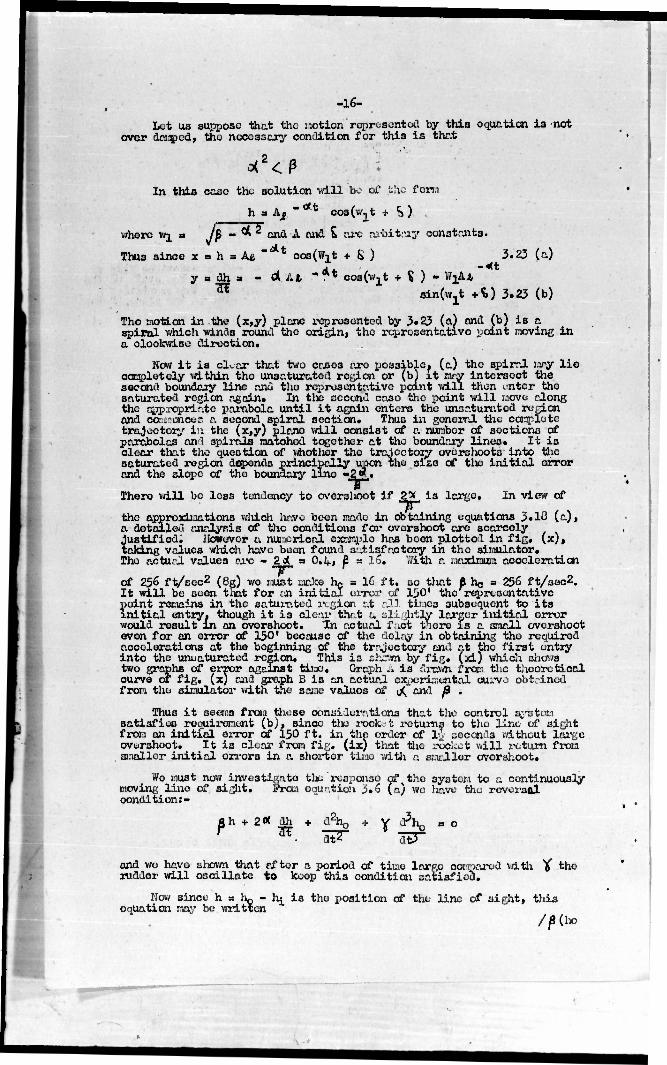
Let us suppose that the r.otion rqjrosontod by this equation is not over damped, the necessary condition for this is that
In thia case the solution vdll bt_- of jbho f orw
I a A, "** cos(w.t + <>)
where w^ • Jp " cni1 *• ^vl • "a,e nrbitn*y constants.
h = Afc "'At ooa(W1t + & ) Thus since x
y a dh a - Ot At " ** soafwvt + $ ) - WjAjfc «t
3.23 (a)
H sin(wjt +^) 3.23 (b)
is a :»ving in
The motion in the (x,y) plane represented by 3»23 (a) and (b) is a spiral which winds round the origin, the representative point movii a cloclcvri.se direction.
Now it is oloar that two cases are possible, (a) the spiral mry lie completely within the unsaturatod region or (bj it mry intersect the second boundary line and the representative point will then «.nter the saturated region again. In tlio second case the point will move along the appropriate parabola until it again enters the unsaturatod region and oaasanQ&S a second spiral section. Thus in general the carpletc trajectory in the (x,y) plane vdll consist of a number of sections of parabolas and spirals matched together at the boundary lines. It is clear that the question of vhother the trajectory overshoots into the saturated region depends principally upon the siao of tlie initial error and the slope of the boundary lino »2«.i
T~ Thero will be loss tendency to overslioot if 2> is large. In view of
the approximations which have been made in obtaining equations 3.1Ö (a), a detailed analysis of the conditions for overshoot are scarcoly justified. However a numerical example has been plotted in fig. (x), taking values which have been found satisfactory in the simulator. The aotU;-.l values arc - 2d a O.kt £ = 16. With a maximum acceleration
T~ of 256 f t/scc2 (gg) Wc nust make e hg = 16 ft. so that I he = 256 ft/sec2.
tial error of 150' the representative point remains in the saturated ivgion at all tii.ies subsequent to its initial entry, though it i3 clear that a alijhtly Iraker initial error would result in an overshoot. "In actual f :-„ct there is a small overshoot even for on error of 150' because of the delay in obtaining the required accelerations at the beginning of the trajectory and at the first entry into the uni.aturated region. This is shSMa by fig, (xi) which shows two graphs of error against time. Graph .* is drawn from the theoretical curve of fig. (x) and graph B is an actual experimental curve obtained from the simulator with the same valuos of uQ"and ß .
Thus it seems from those considerations that the control system satisfies roouircnont (b), since tlie rock, t returns to the lino of sight from an initfal error of 150 ft. in the order of l-2 seconds vrithcut large overshoot. It is clear from fig. (ix) that the roc'.cot will return from smaller initial errors in a shorter tine with a smaller overshoot,
We nust now investigate tit response of the system to a continuously moving lino of sight. From equation 3,6 (a) we have the reversal condition:-
«h + 2« ah r 7TE Y *\
dt3~
and wc have shown that rf tor a period of time large compared with Y the rudder will oscillate to keep thi3 condition satisfied.
Now since h a h- - h: is the position of the lino of sight, this equation nay be written
/p(ho
-17-
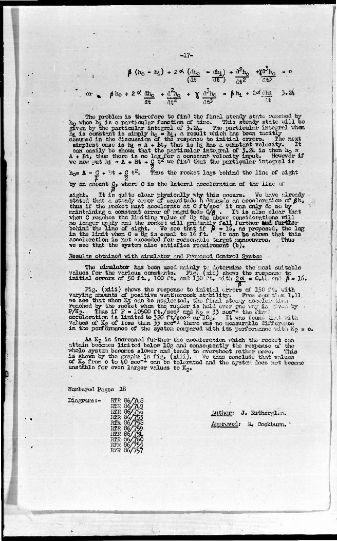
P (ho " **) • 2 * (jÜic - %) + tl2ho +l(^ho • ° (at TF) ~p~ dtT"
or . flho + 2<X aho + ftTfa + V fl?ha = 8 h* + 2>*cihi 3.24 at at* at? !t
Tho problem is therefore to find the find steady stete reached by hp when hi is a particular function of time. Thi3 steady state will be given by the particular integral of 3.24. She parti «Ml fir integral when hi is constant i3 simply ho a hj., a result which has been tacitly assumed in the discussion of the response to initial errors. The next simplest case i3 hi • A + Bt, that is hi has a constant velocity. It con easily bo shown that the particular integral of 3 •24 is then IIQ a
A + Bt, tJ-.us there is no leg for ft constant velocity input. However if we now put lii a A + Bt + C tz wo find that the particular integral is
"2" ho= A - C + Bt + C t2. Thus the rocket lags behind the line of sight
T "5 by an mount C, where C is the lateral acceleration of the line of
sight. It is quite clear physically why this occurs. We have tJLready stated that a steady error of Magnitude n ftmaonfla on acceleration of ßh, thus if tho recket wüst accelerate at C ft/soc*" it can only do so by maintaining a constant error of magnitude C/ß . It is also clear that when C reaches the lir.dting value of 8g the above considerations will no longer apply and the rooko t will gradually fall further end further boliind the Tine of sight. Wo sec that if jg = 16, as proposed, the laß in the limit when C s 8g ia enual to 16 ft. It can be 3hcwn that this acceleration is not exceeded for reasonable target manoeuvres. Thus we see that the system also satisfies requirement (b).
Results obtained with simulator and Proposed Control Syataa
The sinulator has been used mainly to determine the :.;ost suitable values for tho various const.j-its. Pi". (;di) shows the response: to initial errors of 50 ft., 100 ft, and 150 rt. v.ith 2<* u 0.^. cad ß= 16.
Pig. (xiii) shows the response to initial >.rrors of 150 ft» ...ith varying amounts of positive weathercock stability. Pro::' cm: tdun 1.11 we see that when K3 can be neglected, tho final atoaCy 0600X01- .tiLcii reached by the rocket when the ruader is held over one wry is -i.v^i bv P/K-2- T}1US if P = 10500 f t./sec^ and Ko = 33 scc-1 the i'in-1 acceleration is limited to 320 ft/sec'- or J.0r. It «as found thai with values of K2 of loss than 33 soo*l thoro wa3 no measurable difference in the performance of the system compared with its performance with K2 = <
As K2 is incroasod further the acceleration which the rocket cu\ attain becomes limited below 10g anil consequently tho response of the whole 3y3tom becomes slower and tends to overshoot rather more. This is shown by the graphs in fig. (xiii). • We thus conclude that values of Ko from o to 40 sec"x can be tolerated and the ayatem doe3 not become unstable for even larger values to K2.
Numbered Pages 18
Diagrams:- RTR 86/748 RTR 86/742 EPH a r%?56 .Author: J. Hrfcherplui. RTR 86^753 RTR 86/759 Approved: 8. Cookburn.
HEB 86/760 RPH 86/755 ETR 86/757

-18-
JtfPHKDIX I List of Syribola used in dflscxlbing the aeroaynaKLo ————— characteristics of Lon£ Shot.
SYMBOL rEscagi^'ia. DIMKMSICNS
*f Angle between tangent to flight path nad fixed Radians datun line
0 Angle between heading and fixed data.' line Ite/lians
Hi Angle of incidence or yaw» equal to (jrf - *+*) Radians
h^ Lateral distance of rocket frcr: fixou datura Foot
hQ Lateral distance of line of sight f ron fixed Feet datuu
h Latei*al distance of locket fron line of sight, Poet equal to ho - hi
V Forward velocity of rocket Pect/soc.
Ki Constant of proportionality between angle of Tine incidence end rate of turn of flight path
Q Initial angular acceleration of heading Radians/sec produced v/hen full rudder is applied
P Final rate of change of lateral acceleration Toot/svio? pi-oduced when full rudder is applied v/ith neutral weathercock stability, eoual to Qu
K2 weathercock stability constant defined as Sec reduction of angular acceleration of leading per unit rate of turn of flight ixith
K» notary flcniping constant oppressed as reduction Sec * of angular acceleration of heading per unit
rate of turn of hsadin,--
-1
,-1
3.NQ.B2383

%.
a. to
2.<o
a _
4 V) Z * u .to K
?Ä| M iatais

m^HHv

k
i58fc
! ! 0
"> "^ i i
• ,
i
• \
! X ! \ 1 i
i
a ! ! \ I
$ \ 1
v V ] j
r \ 1 p i /
i [ ' 5 M
! ; 1 1 S i i
! i r
"at 1 i ! i i i 1
an I
/ •SJK
* 1 \ ! | i 1 1
I
P
/ / t>
/ /
— i p • !
0
5 1
j
i ..
d
cr Id
<
9 I
II
CO " Z* Qo 5-
öS üJLL.
to
Lü CO Z O Q. CO LÜ a
<^ 00
.(£ *? a. *
0 z

JH nm Mi",!
i
'|
•!
I
i
if. j 1 | j
6i: I
i
°
it
:, ; '' 1 It — «a
pi
I
F E; i:
;' H,
|
( 11 s Vi
H i i.
=
•
)l
j il ' (1 -
i»
__^J " 4/
"N. VJ >>
i. 1 / >d
y/ ^ "
Ik , o„ 1 'i //• £? ii.
?! |l /".. ;• .;< '
i» >1) II
- . IS i
i
-: •; '
l! i
'"'•-'I II i
I'., j. i i| n , ii j i j
'('•1:1 if" - ii i'" I
; •
1 1 1 !' !
!!,
ji l| III "
rf
3
-
• I1 Ii .. 'If
% // i
- :
/ ** ^
p**^
/ 4 7*-
V ^ / /
y .1
y f/ • u
\ \ // // /
/ 1 ii
\ ''% ,* --'"'
Q, / y.
\ J i
/ / < j \ ) / 1 / \f MM ;" ' ' . k
'., i'F'lft:'1 /;, 'aSa, v_ r /' c > i i ; f -1 i . n
1 . \
;„ ^ Ji
V II r II"
1 ii
•
' • " 5 j
1" II 1
I.., 1 -.-V
i j y i n
ä [] y
\'!'"
' j 11;
_J1
3
is j|,r ^t \
ii N ' i» . : ]r"= 1 »ii
Si r :• . , III-
• .If,,
!.
A|K IS8Sg \
M ;. 6 P i. il': i
/ —
jl
ji 1
: • II
1
I! .. il if fl t
•
-— — — — • |
;« •
|
^ |
k -: • i •••' '• ••• • •
LM
.
; "'|
• i


N a
IS
j; 1 °" - (?
1
o
"
1 ;; 11
1 Ij ' ,{ ^ i s
,. *
! 1 i
II" . .. . 1 ' ••'• 1 • j "
. jl
, ! •1
!' «"1 ' ' I
J A ; ' i L^ v i
; isi^rl" -' I -•' -T - ' , \
|. \ ! • ,- j! ^
*\ ' f - II 1 •' _j_ r .1 1 i •" . '
!
- i .. I . iv,
i ;
. .1 ' [ 1
'[•• ! |. ! i
V ' .
|! , [i i 1 /
/' . 1 , i ! i i
' ii 1!
* • 'l r /' i
1 1 Ljl
h i, r v/ ''•! /
if" r 1 y.1' J ' |f ! 1 ii ; . 1 I'
1 • II " i > , • 'I ; 1
1 m o
/(„ ' *l • •J^'"
! •
1 •
l" . ' -
1 J^\ 3 ^ y j ,"
f i .
:,- 1; j- ^'. t
i - \s j' • f: f n
" i.!' /
/ f!
' 1 " ii L' Mi 1 ••
" ''' /' '
in .
J! !'
" I / /
. -1; • -
1! „ /
o ••
It" ' 1 / / :?, !'j|'! /
/ ../
ji ; 1 jj /; 1 '/'.•
'
'1, • jui , k t
• ' } i':. jii
^7 . II
ill ,;| j '< .-i!
c r c 5 • n • c > a Ii"
>-3* flLP
3£ g il X 2^ v2 3
•
: -jo.
«T5 ; ' i.
•-1 0 In
S v- a 8 S3 i5g.
6 •
in si
•• j *
* £ <D cc Hi O He ce S 1 UJ y o
L if! M 0 < B ,ju
O t 2 F Of O
u z
UJ en z O a CO UJ cr cc G
CO
r i
'

o»
* -
ÄS X
13
;-e H 2 w
-2. z • ££ «f 9 m OZi Ott« 8 •» * o J — Ill II
• la* OF
15
STA
BI
ÜTY • * e s OU I* %o 2? ÜJQr;
ui a VJ Z O 0 TI
AL
ATH
E
ZS p*
UI
w z a z ~
u z
UJ I/) z O a.
a. \
I— Z
o <
O z
if) Tn*
tiWD
d. z>

'• ! ! i i | ; i 1 o
•
! V - " I
I 1
«h i A
j •
| I 1 ,— }, 1
* —i
]• in ,~
.. I
o\ i i 1 o !
]
* / 1 y • (
«I i 1
p^^ ji 1 /
<n <a •
/ /
1 X
O 1
o
" * • I
I I \
/ Q
m 6
7 j *^--
1
^J
S|5«2ioo"o2 \ • 1 1
I | j
. ( . •
£
1
o
| f 1 «i
; 1 ( v
T
1 i ~ in
! )
in
! Z o o <: i
i <n
j o ! S «"1
! j | j 1
1 i ) i W
O i in 6 (
J_ j I ! I i t > t ! 1 i
j •
i * s < S ; i z in G <o a
8 S z P
feg •£ a! 01 u
ob I/) H
h DI
2 u. 11 Ul :
i


SKEET -{&Vg®j TITLE: Electrical Simulator and Proposed Control System for Long Shot
AUTHOR(S): Hutherglen, J. ORIGINATING AGENCY: Telecommunications Research Establishment, Malvern PUBLISHED BY: (Same)
g-me)
May ' 45 BOC OA£S. Seer. Gt."Brlt. Eng.
«ME3
26 luusnunopo diagrs. graphs
ABSTRACT:
DISTRIBUTION:
The rocket Longshot Is launched from a fighter, is automatically guided toward an enemy aircraft and employs a control system designed for a line of sight trajectory in which it flies on a radio beam kept pointed at the target To investi- gate the stability and performance of various control systems, an electrical simulator was constructed which produces voltages proportional to the movement of the rocket after the application of the controlling rudders. The aerodynamic characteristics of the rocket and the way in which they are simulated are described. A diagram shoos a proposed control system which gave satisfactory performance on the simulator.
DIVISION: Guided Missiles (1) SECTION: Design and Description (12)
ATI SHEET NO.: S-l-12-107
SUBJECT HEADINGS: Missiles, Guided - Foreign research (62935); Missiles, Guided - Control systems - Testing (62808); Missiles, Guided - Aerodynamics (62350); Simulators, Control (86725)
Air Documents Division, IntclliQonco Dcpartmont Air Matariol Command'
AIB TECHNICAL INDEX SECRFT
KTrlght-Pattoraon Air Forco Qaoo Dsytca, Cn!o -J

CLASSIFICATION CHANGED
B*U*^H^ ^ ^-UU^ ySC0
ySU^ yts. #:

SECRET TITLE: Electrical Simulator aod Proposed Control System for Long Shot
ATTD- 1008
(None) AUTHORfS):' Rutherglen, J. ORIGINATING AGENCY: Telecommunications Research Establishment, Malvern R T1660 PUBLISHED BY: (Same) 1CU3MKO AOCKCTKO.
(E".me) 'DATO
May ' 45 DOC OAS3- Seer.
COUNTRY Gt. Brit. En«.
ruKS 28
tuusTuiwa diaers, graphs
ABSTRACT:
The rocket Longshot is launched from a fighter, is automatically guided toward an enemy aircraft and employs a control system designed for a line of sight trajectory in which it flies oo a radio beam kept pointed at the target. To investi- gate the stability and performance of various cootrol systems, an electrical simulator was constructed which produces voltages proportional to the movemeot of the rochet after the ppplicatloo of the controlling rudders. The aerodynamic characteristics of the rochet and the way in uhlch they are simulated are described. A diagram shoos a proposed control system which gave satisfactory performance on thn otonlntop.
DISTRIBUTION: Copies of this report may be obtained only by U.S. Military Ornanlzattoaa DIVISION: Guided missiles (1) SECTION: Bssißn and Description (12)
ATI SHEET KO-: 8-1-11-107
SUBJECT HEADCKSS- XJiasUes, CaliJd - Foreign reser-ea (32039); MissUeo, Cjtfcd - Control systems - Tostlcj (03003); UfcioUoo, Gat&d • /orofiynaatco (Q2330); SlBinlaSoro, Ccclrol (00733)
1 Ctha tiKSIIcscss Bcp=c=l S5CQST
