to the construction plans, specifications and contract ...mselex.com/wp/addenda/addendum no...
TRANSCRIPT

Addendum #2 - 18529-02
Addendum No. 2
To the
Construction Plans, Specifications and Contract Documents
for the
Construction of Line 12, BOPET FILM
for
Flex Films (USA), Inc.
Elizabethtown, Kentucky
Date: August 11, 2011
MSE Project Request for Bid No. 8529-02
Bid Date: August 31, 2011
Bidder shall conform to the following changes as same shall become binding upon the contract to be issued
in response to this Request for Bid.
Item 1: The Table of Contents for Division XV - Mechanical is revised; please replace this sheet in the
specifications. This is the first sheet after the Division XV header and is also shown as the 4 pageth
of the Table of Contents at the front of all specifications.
Item 2: SECTION 15100 - PIPING & VALVES. 2.01 J. Hot Oil Piping - Requirements for radiographic testing
of 10% of welded joints have been added.
Item 3: SECTION 15562 - FLUID HEATER; changes were made to the numbering of the Section to
coordinate with the Table of Contents. No other changes were made to this Section.
Item 4: NOTE: INDEX OF DRAW INGS. On the INDEX OF DRAW INGS Sheet IDX-1, the information for
Sheet E-001E was provided on Sheet ME-001. Therefore, Sheet E-001E was not issued and can
be deleted on Sheet IDX-1 and the provided Sheet ME-001 contains both Mechanical and Electrical
information for the Rail Unloading Equipment Building.
Also, the Index reference for Drawing No. 110 – PS-101-Overall Equipment Foundation should be
corrected to read Drawing No. PS-100 Overall Equipment Foundation (no change in the drawing).
End of Addendum No. 2
Attachments: Revised Table of Contents for DIVISION XV - MECHANICAL
Revised SECTION 15100 - PIPING & VALVES
Revised SECTION 15562 - FLUID HEATER

FILMS, U.S.A, LLC 1221 NORTH BLACK BRANCH ROAD
ELIZABETHTOWN, KENTUCKY 42702
Div 15 Table of Contents
DIVISION 15 - MECHANICAL 15050 Basic Mechanical Materials and Methods ........................................ 22 15100 Piping & Valves………………………………………………….14 15127 Expansion Fittings & Loops .................................................................4 15135 Gages & Meters………………………...............................................5 15140 Supports & Anchors………………………………… .......................7 15170 Motors………………… ......................................................................4 15190 Mechanical Identification…………………........................................2 15245 Vibration Isolation………………………………………………..4 15260 Insulation…………………………………………………………7 15310 Fire Protection Piping…………………………………………….6 15325 Sprinkler Systems………………………………………………...6 15360 FM-200 Fire Suppression System………………………………...5 15430 Plumbing Specialties……………………………………………..6 15440 Plumbing Fixtures………………………………………………..4 15450 Plumbing Equipment……………………………………………..3 15481 Compressed Air System………………………………………….7 15515 Hydronic Specialties……………………………………………..5 15540 HVAC Pumps……………………………………………………4 15545 Chemical Water Treatment……………………………………….6 15550 Fuel Fired Heaters………………………………………………..4 15562 Fluid Heater……………………………………………………..11 15575 Breeching, Chimneys & Stacks…………………………………..3 15640 Packaged Cooling Towers………………………………………..6 15684 Centrifugal Chillers………………………………………………9 15738 Split System Air Conditioning Units……………………………..4 15855 Air Handling Units………………………………………………12 15870 Power Ventilators……………………………………………..........4 15890 Ductwork………………………………………………………….5 15905 HVAC Instrumentation .................................................................... 10 15910 Ductwork Accessories………………………………………… ......5 15940 Air Outlets & Inlets…………………………………… ...................2 15985 Sequence Of Operation…………………………………………...4 15990 Testing Adjusting and Balancing…………………………..…….10

FLEX FILMS, U.S.A, LLC 1221 NORTH BLACK BRANCH ROAD ELIZABETHTOWN, KENTUCKY 42702
PIPING & VALVES 15100 - 1
SECTION 15100 - PIPING & VALVES PART 1 GENERAL 1.1 SECTION INCLUDES
A. Pipe; pipe fittings, valves, and connections for piping systems.
1. Sanitary sewer. 2. Domestic water. 3. Natural gas. 4. Cooling Water 5. Condensate Removal 6. Hot Oil Piping
7. Gas meters 8. Gas regulators. 1.2 RELATED SECTIONS
A. Section 15245 - Vibration Isolation.
B. Section 15260 - Mechanical Insulation.
C. Division 16 - Equipment Wiring Systems: Electrical characteristics and wiring connections. 1.3 REFERENCES
A. ASME B31.1 - Power Piping.
B. ASME B31.2 - Fuel Gas Piping.
C. ASME B31.9 - Building Service Piping.
D. NFPA 54 - National Fuel Gas Code.
E. ASME - Boiler and Pressure Vessel Code.
F. Kentucky Building Code. G. Kentucky Plumbing Code.
H. Kentucky Boiler Code. I. IMC, International Mechanical Code.
1.4 SUBMITTALS FOR REVIEW
FLEX FILMS, U.S.A, LLC 1221 NORTH BLACK BRANCH ROAD ELIZABETHTOWN, KENTUCKY 42702
PIPING & VALVES 15100 - 2
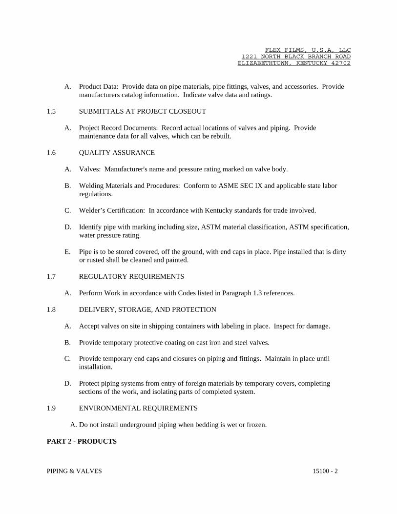
A. Product Data: Provide data on pipe materials, pipe fittings, valves, and accessories. Provide
manufacturers catalog information. Indicate valve data and ratings. 1.5 SUBMITTALS AT PROJECT CLOSEOUT
A. Project Record Documents: Record actual locations of valves and piping. Provide maintenance data for all valves, which can be rebuilt.
1.6 QUALITY ASSURANCE
A. Valves: Manufacturer's name and pressure rating marked on valve body.
B. Welding Materials and Procedures: Conform to ASME SEC IX and applicable state labor regulations.
C. Welder’s Certification: In accordance with Kentucky standards for trade involved. D. Identify pipe with marking including size, ASTM material classification, ASTM specification,
water pressure rating. E. Pipe is to be stored covered, off the ground, with end caps in place. Pipe installed that is dirty
or rusted shall be cleaned and painted. 1.7 REGULATORY REQUIREMENTS
A. Perform Work in accordance with Codes listed in Paragraph 1.3 references. 1.8 DELIVERY, STORAGE, AND PROTECTION
A. Accept valves on site in shipping containers with labeling in place. Inspect for damage. B. Provide temporary protective coating on cast iron and steel valves.
C. Provide temporary end caps and closures on piping and fittings. Maintain in place until
installation. D. Protect piping systems from entry of foreign materials by temporary covers, completing
sections of the work, and isolating parts of completed system. 1.9 ENVIRONMENTAL REQUIREMENTS
A. Do not install underground piping when bedding is wet or frozen. PART 2 - PRODUCTS

FLEX FILMS, U.S.A, LLC 1221 NORTH BLACK BRANCH ROAD ELIZABETHTOWN, KENTUCKY 42702
PIPING & VALVES 15100 - 3
2.1 PIPING SCHEDULE
A. Furnish and install piping of sizes and locations shown on the drawings. Piping and fitting material shall be as shown in the accompanying table.
B. Table of Piping Fittings (Interior)
Service Sizes Pipe Fittings Domestic Cold Water All Sizes Schedule 40 pvc Glue Joints Domestic Hot Water All Sizes Schedule 40 cpvc Glue Joints Hot Oil Piping 2" and Smaller Sch. 40 A106 Seamless Std. Wt. Welded Hot Oil Piping 2-1/2" and Larger Sch. 40 A106 Seamless Std. Wt. Welded Chilled Water
2" and Smaller Sch. 40 ASTM A53 Black Steel
125 lb.Screwed Joints
Chilled Water 2-1/2" and Larger
outside of Mechanical Room
Sch. 40 ASTM A53 Black Steel
Flanged or Welded Joints
Chilled Water 2-1/2” and Larger inside Mechanical Room
Sch. 40 ASTM A53 Black Steel
Flanged or Welded Joints
Condenser Water All Sizes outside
of Mechanical Room
Sch. 40 ASTM A53 Black Steel or Schedule 40 pvc
Flanged, Welded or Glue Joints
Condenser Water All Sizes inside Mechanical Room
Sch. 40 ASTM A53 Black Steel
Flanged Joints
Condensate Drain All Sizes DWV PVC Glue Joints
Roof Leader (Above Slab)
All Sizes DWV PVC Glue Joints
Storm Sewer (Below Slab)
All Sizes
DWV PVC Glue Joints
Gas 2" and Smaller Sch. 40 Black Steel 125 lb.
Malleable Iron Screwed
Gas 2-1/2" and Larger Sch. 40 Black Steel Std. Wt., Welded

FLEX FILMS, U.S.A, LLC 1221 NORTH BLACK BRANCH ROAD ELIZABETHTOWN, KENTUCKY 42702
PIPING & VALVES 15100 - 4
Screwed fittings shall be Midwest, Grinnell, Crane or equal. Welding fittings shall be long
radius type, Tube Turns, Midwest, Crane or equal. 1. Refer to separate section for Sprinkler piping.
C. Soil, Waste and Vent Piping - Interior
1. Pipe and Fittings (Above and below slab)
a. All soil, waste and vent piping shall be ASTM D 1785, Schedule 40 PVC with bell and spigot solvent sealed joint ends.
b. Fittings: ASTM D 2466, Schedule 40 PVC.. c. Joints: ASTM D 2855, solvent weld with ASTM D 2564 solvent cement.
D. Domestic Cold Water Piping Above Slab - Interior
1. PVC Pipe: ASTM D1785 Schedule 40. a. Fittings: ASTM D2466, Schedule 40, PVC ASTM D2464 PVC, threaded]. b. Joints: ASTM D2855, solvent weld with ASTM D2564 solvent cement.
E. Domestic Hot Water Piping Above Slab - Interior
1. CPVC Pipe: ASTM D2846/D2846M, chlorinated polyvinyl chloride (CPVC) material. a. Fittings: ASTM D2846/D2846M, CPVC. b. Joints: ASTM D2846/D2846M, solvent weld with ASTM F493 solvent cement.
F. Chilled Water Piping –Interior and Exterior.
1. Steel Pipe: ASTM A 53/A 53M, black steel with plain ends.
2. Cast-Iron Threaded Fittings: ASME B16.4; Class 125.
3. Cast-Iron Pipe Flanges and Flanged Fittings: ASME B16.1, Class, 125. G. Condenser Water Piping - Interior and Exterior
1. Steel Pipe: ASTM A 53/A 53M, black steel with plain ends.
2. Cast-Iron Threaded Fittings: ASME B16.4; Class 125.
3. Cast-Iron Pipe Flanges and Flanged Fittings: ASME B16.1, Class, 125.
4. Schedule 40 PVC, ASTM D1785 pipe with ASTM D2466 fittings, ASTM D2855 joints and ASTM D2564 solvent cement.
I. Condensate Removal Piping - Interior
FLEX FILMS, U.S.A, LLC 1221 NORTH BLACK BRANCH ROAD ELIZABETHTOWN, KENTUCKY 42702
PIPING & VALVES 15100 - 5
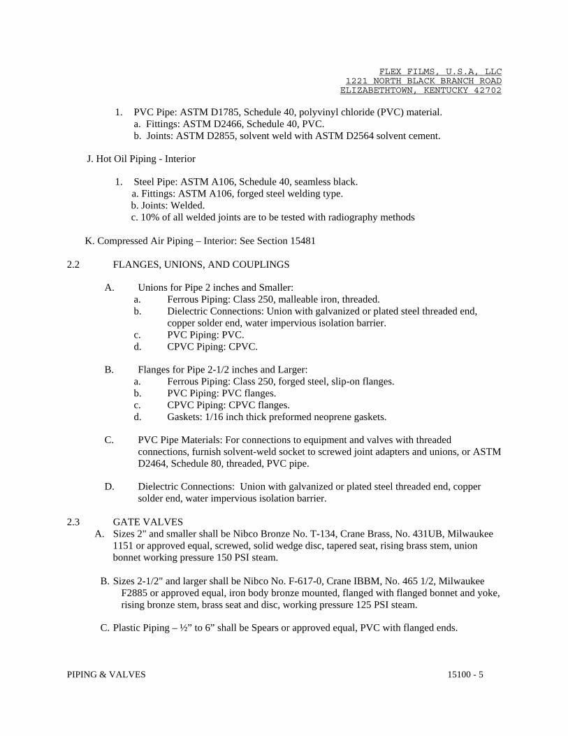
1. PVC Pipe: ASTM D1785, Schedule 40, polyvinyl chloride (PVC) material. a. Fittings: ASTM D2466, Schedule 40, PVC. b. Joints: ASTM D2855, solvent weld with ASTM D2564 solvent cement.
J. Hot Oil Piping - Interior
1. Steel Pipe: ASTM A106, Schedule 40, seamless black. a. Fittings: ASTM A106, forged steel welding type.
b. Joints: Welded. c. 10% of all welded joints are to be tested with radiography methods K. Compressed Air Piping – Interior: See Section 15481
2.2 FLANGES, UNIONS, AND COUPLINGS
A. Unions for Pipe 2 inches and Smaller: a. Ferrous Piping: Class 250, malleable iron, threaded. b. Dielectric Connections: Union with galvanized or plated steel threaded end,
copper solder end, water impervious isolation barrier. c. PVC Piping: PVC. d. CPVC Piping: CPVC.
B. Flanges for Pipe 2-1/2 inches and Larger: a. Ferrous Piping: Class 250, forged steel, slip-on flanges. b. PVC Piping: PVC flanges. c. CPVC Piping: CPVC flanges. d. Gaskets: 1/16 inch thick preformed neoprene gaskets.
C. PVC Pipe Materials: For connections to equipment and valves with threaded connections, furnish solvent-weld socket to screwed joint adapters and unions, or ASTM D2464, Schedule 80, threaded, PVC pipe.
D. Dielectric Connections: Union with galvanized or plated steel threaded end, copper solder end, water impervious isolation barrier.
2.3 GATE VALVES
A. Sizes 2" and smaller shall be Nibco Bronze No. T-134, Crane Brass, No. 431UB, Milwaukee 1151 or approved equal, screwed, solid wedge disc, tapered seat, rising brass stem, union bonnet working pressure 150 PSI steam.
B. Sizes 2-1/2" and larger shall be Nibco No. F-617-0, Crane IBBM, No. 465 1/2, Milwaukee
F2885 or approved equal, iron body bronze mounted, flanged with flanged bonnet and yoke, rising bronze stem, brass seat and disc, working pressure 125 PSI steam.
C. Plastic Piping – ½” to 6” shall be Spears or approved equal, PVC with flanged ends.

FLEX FILMS, U.S.A, LLC 1221 NORTH BLACK BRANCH ROAD ELIZABETHTOWN, KENTUCKY 42702
PIPING & VALVES 15100 - 6
2.4 GLOBE VALVES
A. Sizes 2" and smaller shall be Nibco Bronze No. T-235-Y, Crane Brass, No. 7, Milwaukee 590 or approved equal, screwed renewable composition disc, rising brass stem, working pressure 150 PSI steam.
B. Sizes 2-1/2" and larger shall be Nibco Bronze, No. F-918-B, Crane IBBM, No. 351,
Milwaukee F2981 or approved equal flanged with flanged bonnet and yoke, rising bronze stem, brass seat and disc, working pressure 125 PSI steam.
C. Plastic Piping – ½” to 6” shall be Spears or approved equal, PVC with flanged ends.
2.5 CHECK VALVES (HORIZONTAL)
A. Sizes 2" and smaller shall be Nibco Bronze, No. T-433-B, Crane Brass No. 137, Milwaukee 510 or approved equal, screwed with screwed cap, swing check, renewable bronze disc, working pressure 150 PSI steam.
B. Sizes 2-1/2" and larger shall be Nibco, No. F-918-B, Crane IBBM, No. 373, Milwaukee
F2974 or approved equal, swing check, flanged with flanged cap, bronze seat and disc, working pressure 125 PSI steam.
C. Plastic Piping – 3/4” to 8” shall be Spears or approved equal, industrial swing check valves;
PVC with flanged ends.
2.6 BALL CHECK VALVES
A. Plastic Piping – 1/2” to 8” shall be Spears or approved equal, industrial swing check valves; PVC with flanged ends.
2.7 BUTTERFLY CHECK VALVES
A. Plastic Piping – 2” and larger shall be Spears or approved equal, industrial swing check valves; PVC with flanged ends.
2.8 BALANCING VALVES
A. Sizes 2" and smaller shall be Powell, Figure 2200 or approved equal, 175 PSI WOG, screwed, lubricated plug cock.
B. Size 2-1/2" and larger shall be Powell, Figure 2201 or approved equal, 175 PSIG WOG
flanged, lubricated plug cock. C. Valves, as manufactured by Crane, Keystone, Homestead or equal will be acceptable.
2.9 RELIEF VALVES

FLEX FILMS, U.S.A, LLC 1221 NORTH BLACK BRANCH ROAD ELIZABETHTOWN, KENTUCKY 42702
PIPING & VALVES 15100 - 7
A. Refer to individual articles on heaters or boilers.
2.10 BUTTERFLY VALVES
A. Dezurik, Figure No. 632-LD, Crane, Milwaukee, Keystone, Nibco or approved equal, lug style, semi-steel body, bronzed discs with stainless steel shafts, bronze bushings and infinite position adjustment lever on valves 4" and smaller and enclosed handwheel actuators on all valves 6" and larger.
B. Cooling and Condenser Water - 2 inches through 10 inches: 150 psi at 73 degrees F water temperature, maximum service temperature: 140 degrees F, two piece body, ASTM D1784 PVC, lug type flange facing, disc encapsulated with EPDM, stainless steel shaft, locking lever handle.
2.11 BALL VALVES
A. Domestic Cold Water and Cooling Water - 2 inches and Smaller: 150 psi at 73 degrees F water temperature, maximum service temperature: 140 degrees F ASTM D1784 PVC body and ball, double lever handle, EPDM seals, teflon seats, regular port, single union type with socket ends.
B. Domestic Hot Water - 2 inches and Smaller: 150 psi at 73 degrees F water temperature, maximum service temperature: 210 degrees F, ASTM D1784 CPVC body and ball, double lever handle, EPDM seals, teflon seats, full port, single union type with socket ends.
2.12 EXTERIOR VALVES AND ACCESSORIES
A. Valve - Mueller, Cat. No. A-2480-20, mechanical joint of sizes as required on Drawings. B. Valve Boxes - Mueller, Cat. No. H-10365, flange base. Provide extension piece as required. C. Furnish a valve-operating wrench with socket to fit valves above. Length of wrench to be as
required and shall be equal to Mueller, No. A-24610. D. Valves, as manufactured by Milwaukee, Kennedy, Traverse City or equal will be accepted.
2.13 GAS VALVES
A. Ball Valves - 1/4 inch to 1 inch: MSS SP 110, Class 125, two piece, threaded ends, bronze body, chrome plated bronze ball, reinforced teflon seats, blow-out proof stem, lever handle, UL 842 listed for flammable liquids and LPG, full port.

FLEX FILMS, U.S.A, LLC 1221 NORTH BLACK BRANCH ROAD ELIZABETHTOWN, KENTUCKY 42702
PIPING & VALVES 15100 - 8
B. Ball Valves - 1-1/4 inch to 3 inch: MSS SP 110, Class 125, two piece, threaded ends, bronze body, chrome plated bronze ball, reinforced teflon seats, blow-out proof stem, lever handle, UL 842 listed for flammable liquids and LPG, conventional port.
C. Sizes 2-1/2" and larger shall be Crane, No. 325, all iron, 125 lb. WOG flanged square head cock.
D. Furnish operating handle with each valve.
E. Valves, as manufactured by Milwaukee, Homestead or equal, will be accepted. 2.14 BACKFLOW PREVENTER
A. Type-1 - Furnish and install in the domestic water service, piping where shown, a Watts, Series 909, Febco, Lawler or equal, size 3" reduced pressure backflow preventer, bronze body, 175 PSI working pressure. Assembly shall include test cocks, a pressure differential relief valve located between two (2) positive seating check valves and meeting the requirements of ASSE Standard 1013. Furnish No. 909 AG air gap fitting.
B. Type-2 - Furnish and install where shown Watts Series 709/007, Febco, Lawler or equal
double check valve assembly, bronze body, 175 PSI working pressure. Assembly shall include test cocks, two independent check valves and meeting the requirements of ASSE Standard 1015.
2.15 CHECK VALVES (VERTICAL)
A. Mueller, Fig. No. 107M-A-P, Williams-Hager, Nibco or approved equal, 250 PSI ANSI B16.1 globe type, silent check valve, flanged ends, cast iron body with bronze trim.
2.16 TEMPERING VALVE A. Furnish and install, where shown on the Drawings, Symmons, Model 5-1000A, Powers,
Lawler or equal, thermostatic tempering valve with integral check stops, removable cartridge with strainer, 1-1/2" inlets, 2" outlets, all bronze and stainless steel components, 100 GPM capacity at 20 PSI pressure differential.
2.17 WATER PRESSURE REDUCING VALVES
A. Furnish and install a Watts, Model U5LP, Leslie, Spence or equal pressure reducing valve, 3/4" with a capacity of 20 GPM with 50 PSI inlet pressure and 20 PSI outlet pressure. Valve shall be screwed with union inlet, bronze body, 200 Lb. working pressure, built-in stainless steel strainer and expansion by-pass feature.
B. Furnish and install in main cold water service two (2) Watts Model No. 223, Leslie, Spence or
equal pressure reducing valves, 1-1/4" size with a capacity of 80 gpm each at 20 PSI fall-off pressure. Valves shall be screwed, 300 PSI bronze body with renewable stainless steel seat.

FLEX FILMS, U.S.A, LLC 1221 NORTH BLACK BRANCH ROAD ELIZABETHTOWN, KENTUCKY 42702
PIPING & VALVES 15100 - 9
2.18 CHILLER RELIEF VALVE
A. Bell & Gossett, Model 3300, Watts, Leslie or approved equal, ASME relief valve with 30 PSI setting and a capacity of 3300 MBH.
2.19 GAS PRESSURE REDUCING VALVES
A. Furnish and install in gas piping serving each small plant unit heater an American Meter Co., Rockwell, Fisher, Sprague or equal pressure reducing valve, inlet pressure 2 psig, outlet pressure 0.5 psig maximum, capacity 100 CFH.
B. Furnish and install in gas piping serving each large plant unit heater an American Meter
Co., Rockwell, Fisher, Sprague or equal pressure reducing valve, inlet pressure 2 psig, outlet pressure 0.5 psig maximum, capacity 200 CFH.
C. Furnish and install in gas piping serving the hot oil boiler and as indicated on the drawings
an American Meter Co., Rockwell, Fisher, Sprague or equal pressure reducing valve, inlet pressure 35 psig, outlet pressure 5.0 psig maximum, capacity 14,300 CFH.
D. Furnish and install in gas piping serving all plant unit heaters an American Meter
Co., Rockwell, Fisher, Sprague or equal pressure reducing valve, inlet pressure 35 psig, outlet pressure 2.0 psig maximum, capacity 3500 CFH.
2.20 GAS METER A. Furnish and install in branch gas piping to each fluid heater a gas meter. Meter shall be by American Meter Co. No. 16M-G250, Rockwell, Fisher, Sprague or equal, rotary gas meter Capable of metering 14,300 CFH of gas. 2.21 UNIONS
A. Unions shall be installed at all locations shown on the Drawings and as required for the isolation of all screwed valves and connections to screwed equipment.
B. Unions in steel piping 2" and smaller shall be ground joint, malleable iron, screwed; 250 PSI
working pressure for high pressure steam and return lines and chilled water lines, and 125 PSI working pressure for all other applications.
C. Unions in piping 2-1/2" and larger shall be flanged type with gaskets designed for the working pressure of the unions.
PART 3 - EXECUTION 3.1 EXAMINATION
A. Verify that excavations are to required grade, dry, and not over-excavated.

FLEX FILMS, U.S.A, LLC 1221 NORTH BLACK BRANCH ROAD ELIZABETHTOWN, KENTUCKY 42702
PIPING & VALVES 15100 - 10
3.2 PREPARATION
A. Ream pipe and tube ends. Remove burrs. Bevel plain end ferrous pipe. B. Remove scale and dirt, on inside and outside, before assembly. C. Prepare piping connections to equipment with flanges or unions.
3.3 INSTALLATION
A. Install in accordance with manufacturer's instructions. B. Provide non-conducting dielectric connections wherever jointing dissimilar metals. C. Route piping in orderly manner and maintain gradient. Route parallel and perpendicular to
walls. D. Install piping to maintain maximum headroom, conserve space, and not interfere with use of
space. E. Group piping whenever practical at common elevations. F. Install piping to allow for expansion and contraction without stressing pipe, joints, or
connected equipment. G. Provide clearance in hangers and from structure and other equipment for installation of
insulation and access to valves and fittings.
H. Provide access doors where valves and fittings are not exposed. I. Establish elevations of buried piping outside the building to ensure not less than 3 feet of
cover. J. Install vent piping penetrating roofed areas to maintain integrity of roof assembly.
K. Where pipe support members are welded to structural building framing, scrape, brush clean,
and apply one coat of zinc rich primer to welding. L. Provide support for utility meters in accordance with requirements of utility companies. M. Prepare exposed, unfinished pipe, fittings, supports, and accessories ready for finish painting. N. Install bell and spigot pipe with bell end upstream. O. Install valves with stems upright or horizontal, not inverted.
FLEX FILMS, U.S.A, LLC 1221 NORTH BLACK BRANCH ROAD ELIZABETHTOWN, KENTUCKY 42702
PIPING & VALVES 15100 - 11
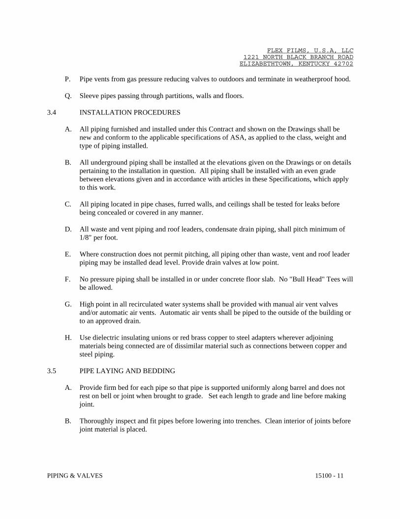
P. Pipe vents from gas pressure reducing valves to outdoors and terminate in weatherproof hood. Q. Sleeve pipes passing through partitions, walls and floors.
3.4 INSTALLATION PROCEDURES
A. All piping furnished and installed under this Contract and shown on the Drawings shall be new and conform to the applicable specifications of ASA, as applied to the class, weight and type of piping installed.
B. All underground piping shall be installed at the elevations given on the Drawings or on details
pertaining to the installation in question. All piping shall be installed with an even grade between elevations given and in accordance with articles in these Specifications, which apply to this work.
C. All piping located in pipe chases, furred walls, and ceilings shall be tested for leaks before
being concealed or covered in any manner. D. All waste and vent piping and roof leaders, condensate drain piping, shall pitch minimum of
1/8" per foot. E. Where construction does not permit pitching, all piping other than waste, vent and roof leader
piping may be installed dead level. Provide drain valves at low point. F. No pressure piping shall be installed in or under concrete floor slab. No "Bull Head" Tees will
be allowed. G. High point in all recirculated water systems shall be provided with manual air vent valves
and/or automatic air vents. Automatic air vents shall be piped to the outside of the building or to an approved drain.
H. Use dielectric insulating unions or red brass copper to steel adapters wherever adjoining
materials being connected are of dissimilar material such as connections between copper and steel piping.
3.5 PIPE LAYING AND BEDDING
A. Provide firm bed for each pipe so that pipe is supported uniformly along barrel and does not rest on bell or joint when brought to grade. Set each length to grade and line before making joint.
B. Thoroughly inspect and fit pipes before lowering into trenches. Clean interior of joints before
joint material is placed.

FLEX FILMS, U.S.A, LLC 1221 NORTH BLACK BRANCH ROAD ELIZABETHTOWN, KENTUCKY 42702
PIPING & VALVES 15100 - 12
C. Lay to uniform grade between elevations shown or to pitch indicated. Use Engineer's level and transit along with adequately spaced and supported batter boards to establish horizontal and vertical control. Lay bell and spigot pipe with bells upstream.
D. For each pipe which passes under a footing or grade beam, provide steel pipe sleeve, with at
least two (2) inches clearance around pipe and extending eighteen (18) inches beyond each side of footing or grade beam. Before backfilling, pack space between pipe and sleeve for a depth of two (2) inches at each end of sleeve with oakum or yarn to prevent the entrance of dirt. If pipe is installed before footing or grade is constructed, place compacted backfill around sleeve. If pipe is installed after building work is constructed, backfill with concrete to a thickness of at least six (6) inches around sleeve and up to the footing or grade beam.
E. Close open ends of piping during construction to prevent earth entering lines. Close ends of
lines and unused openings in fittings. F. Provide concrete thrust blocks for water piping as indicated or required to resist any thrust that
may be encountered. 3.6 APPLICATION
A. Use grooved mechanical couplings and fasteners only in accessible locations. B. Install unions downstream of valves and at equipment or apparatus connections. C. Install brass male adapters each side of valves in copper piped system. Solder adapters to
pipe. D. Install gate, ball or butterfly valves for shut-off and to isolate equipment, part of systems, or
vertical risers. E. Install globe ball or butterfly valves for throttling, bypass, or manual flow control services. F. Provide lug end butterfly valves adjacent to equipment when provided to isolate equipment. G. Provide spring loaded check valves on discharge of water pumps. H. Provide plug valves in natural gas systems for shut-off service. I. Provide flow controls in water recirculating systems where indicated.
3.7 DISINFECTION OF DOMESTIC WATER PIPING SYSTEM
A. Prior to starting work, verify system is complete, flushed and clean. B. Ensure Ph of water to be treated is between 7.4 and 7.6 by adding alkali (caustic soda or soda
ash) or acid (hydrochloric).

FLEX FILMS, U.S.A, LLC 1221 NORTH BLACK BRANCH ROAD ELIZABETHTOWN, KENTUCKY 42702
PIPING & VALVES 15100 - 13
C. Inject disinfectant, free chlorine in liquid, powder, tablet or gas form, throughout system to
obtain 50 to 80 mg/L residuals. D. Bleed water from outlets to ensure distribution and test for disinfectant residual at minimum
15 percent of outlets. E. Maintain disinfectant in system for 24 hours. F. If final disinfectant residual tests less than 25 mg/L, repeat treatment. G. Flush disinfectant from system until residual equal to that of incoming water or 1.0 mg/L. H. Take samples no sooner than 24 hours after flushing, from 10 percent of outlets and from
water entry, and analyze in accordance with AWWA C651. 3.8 SERVICE CONNECTIONS
A. Provide new sanitary and storm sewer services. Before commencing work check invert elevations required for sewer connections, confirm inverts and ensure that these can be properly connected with slope for drainage and cover to avoid freezing.
B. Provide new water services complete with approved reduced pressure backflow preventers.
1. Provide sleeve in wall for service main and support at wall with reinforced concrete bridge. Caulk enlarged sleeve and make watertight with pliable material. Anchor service main inside to concrete wall.
C. Provide new gas service complete with gas meter and regulators. Gas service distribution
piping shall have pressures as indicated on the drawings. Provide regulators on each line serving gravity type appliances, sized in accordance with equipment.
END OF SECTION
FLEX FILMS, U.S.A, LLC 1221 NORTH BLACK BRANCH ROAD ELIZABETHTOWN, KENTUCKY 42702
FLUID HEATERS 15562 - 1
SECTION 15562
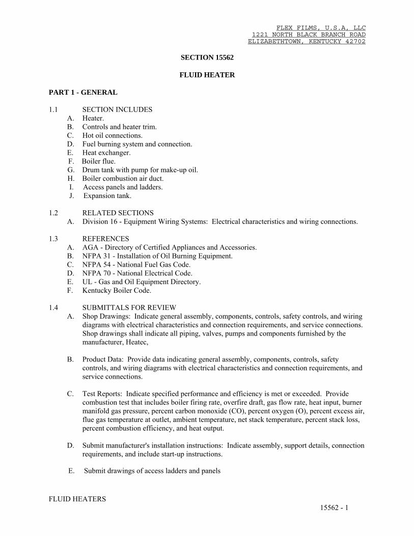
FLUID HEATER PART 1 - GENERAL 1.1 SECTION INCLUDES
A. Heater. B. Controls and heater trim. C. Hot oil connections. D. Fuel burning system and connection. E. Heat exchanger.
F. Boiler flue. G. Drum tank with pump for make-up oil. H. Boiler combustion air duct. I. Access panels and ladders. J. Expansion tank. 1.2 RELATED SECTIONS
A. Division 16 - Equipment Wiring Systems: Electrical characteristics and wiring connections. 1.3 REFERENCES
A. AGA - Directory of Certified Appliances and Accessories. B. NFPA 31 - Installation of Oil Burning Equipment. C. NFPA 54 - National Fuel Gas Code. D. NFPA 70 - National Electrical Code. E. UL - Gas and Oil Equipment Directory. F. Kentucky Boiler Code.
1.4 SUBMITTALS FOR REVIEW
A. Shop Drawings: Indicate general assembly, components, controls, safety controls, and wiring diagrams with electrical characteristics and connection requirements, and service connections.
Shop drawings shall indicate all piping, valves, pumps and components furnished by the manufacturer, Heatec,
B. Product Data: Provide data indicating general assembly, components, controls, safety
controls, and wiring diagrams with electrical characteristics and connection requirements, and service connections.
C. Test Reports: Indicate specified performance and efficiency is met or exceeded. Provide
combustion test that includes boiler firing rate, overfire draft, gas flow rate, heat input, burner manifold gas pressure, percent carbon monoxide (CO), percent oxygen (O), percent excess air, flue gas temperature at outlet, ambient temperature, net stack temperature, percent stack loss, percent combustion efficiency, and heat output.
D. Submit manufacturer's installation instructions: Indicate assembly, support details, connection
requirements, and include start-up instructions. E. Submit drawings of access ladders and panels

FLEX FILMS, U.S.A, LLC 1221 NORTH BLACK BRANCH ROAD ELIZABETHTOWN, KENTUCKY 42702
FLUID HEATERS 15562 - 2
F. Manufacturer's Certificate: Certify that units meet or exceed specified requirements.
G. Manufacturer's Field Reports: Indicate condition of equipment after start-up including control
settings and performance chart of control system.
H. Operation and Maintenance Data: Include manufacturer's descriptive literature, operating instructions, cleaning procedures, replacement parts list, and maintenance and repair data.
1.5 QUALITY ASSURANCE
A. Manufacturer: Company specializing in manufacturing the Products specified in this section with minimum three years documented experience.
B. Installer: Company specializing in installing and servicing the products of this section with
minimum three years documented experience approved by manufacturer. 1.6 REGULATORY REQUIREMENTS
A. Conform to ASME SEC 1 and UL 726 for construction of boilers.
B. Units: UL labeled.
C. Conform to applicable NFPA 70 code for internal wiring of factory wired equipment.
D. Products Requiring Electrical Connection: Listed and classified by Underwriters'
Laboratories, Inc., testing firm acceptable to the authority having jurisdiction as suitable for the purpose specified and indicated.
1.7 DELIVERY, STORAGE, AND PROTECTION
A. Protect boilers from damage by leaving factory inspection openings and shipping packaging in place until final installation.
1.8 WARRANTY
A. Section 01700 - Execution Requirements: Product warranties and product bonds.
B. This Contractor shall furnish as part of his bid, an unlimited two year parts and labor warranty on equipment provided in this section. At the end of the two year warranty period any parts listed in the “Extra Materials” section of this specification that were used shall be replaced at no additional charge. The two year warranty period shall begin at the Date of Substantial Completion.
1.9 MAINTENANCE SERVICE
A. Provide service and maintenance of boilers for two years from Date of Substantial Completion.

FLEX FILMS, U.S.A, LLC 1221 NORTH BLACK BRANCH ROAD ELIZABETHTOWN, KENTUCKY 42702
FLUID HEATERS 15562 - 3
PART 2 - PRODUCTS 2.1 MANUFACTURERS
A. Heatec B. A company approved by the Owner a minimum of seven days prior to the bid opening.
2.2 FLUID HEATER COMPONENTS
A. Heatec model HCI-10010-50-D thermal fluid heater. B. Burner C. Blower for burner. D. Control panel. E. Gas train F. Economizer. G. Air pre heater. H. Flue gas stack. I. Expansion tank. J. Drain tank. K. Triplex pump package. L. Barrell pump. M. Boiler combustion air duct.
2.3 SPARE PARTS TO BE SUPPLIED AT TIME OF STARTUP
A. All parts shall be replenished for a two year period after startup. B. Scanner C. Module programmer EP170 D. Module display ED510 E. Module amplifier EUVS4 F. Cable ribbon E350-3 (Expansion) G. Module expansion E320 H. Relay RH4B-UL AC240V I. Silicone tube red high temp RTV J. Ignition transformer K. Control temp limit UL350L-00 L. Control temp module UT450-04 M. Spark igniter eclipse vorto N. Electrical damper actuator.
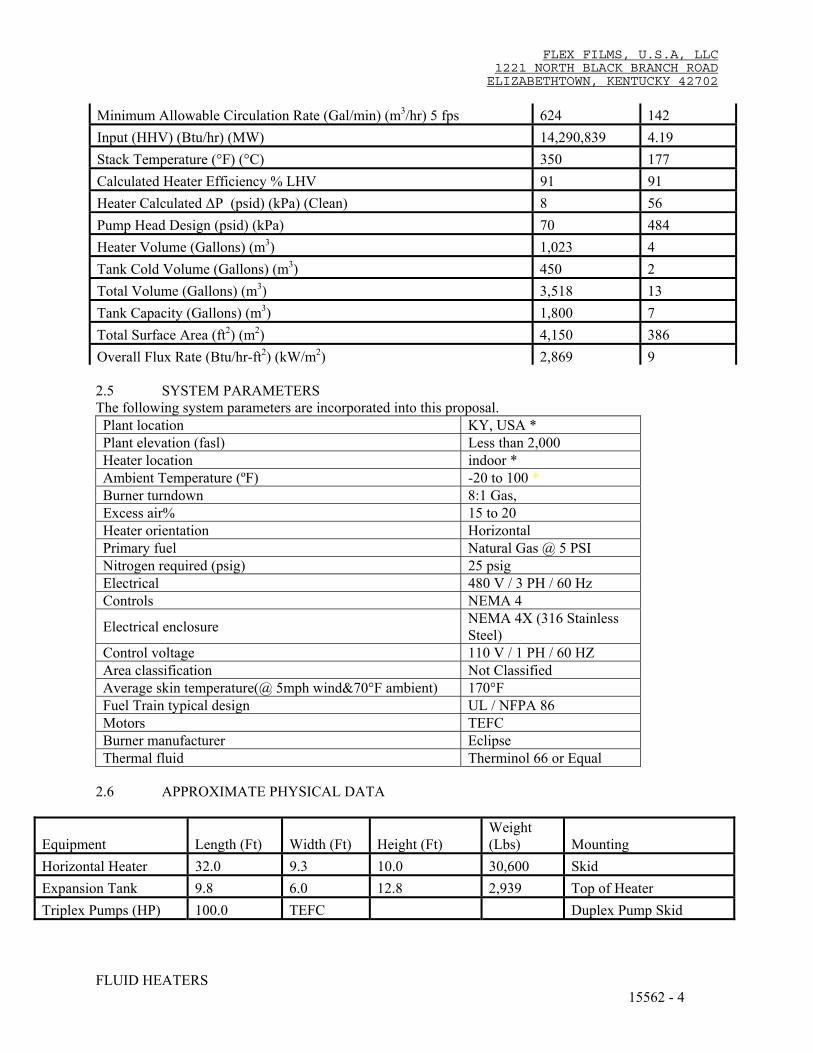
2.4 EQUIPMENT SCHEDULE IP UNITS SI UNITS Heater Capacity (Btu/hr) (MW) 11,904,963 3.49 Heater Circulation Rate (Gal/min) (m3/hr) 1,100 250 Heater Inlet Temperature (°F) (°C) 529 276 Heater Outlet Temperature (°F) (°C) 572 300 Minimum Allowable Circulation Rate (Gal/min) (m3/hr) 80 % 880 200
FLEX FILMS, U.S.A, LLC 1221 NORTH BLACK BRANCH ROAD ELIZABETHTOWN, KENTUCKY 42702
FLUID HEATERS 15562 - 4
Minimum Allowable Circulation Rate (Gal/min) (m3/hr) 5 fps 624 142 Input (HHV) (Btu/hr) (MW) 14,290,839 4.19 Stack Temperature (°F) (°C) 350 177 Calculated Heater Efficiency % LHV 91 91 Heater Calculated ∆P (psid) (kPa) (Clean) 8 56 Pump Head Design (psid) (kPa) 70 484 Heater Volume (Gallons) (m3) 1,023 4 Tank Cold Volume (Gallons) (m3) 450 2 Total Volume (Gallons) (m3) 3,518 13 Tank Capacity (Gallons) (m3) 1,800 7 Total Surface Area (ft2) (m2) 4,150 386 Overall Flux Rate (Btu/hr-ft2) (kW/m2) 2,869 9 2.5 SYSTEM PARAMETERS The following system parameters are incorporated into this proposal. Plant location KY, USA * Plant elevation (fasl) Less than 2,000 Heater location indoor * Ambient Temperature (ºF) -20 to 100 * Burner turndown 8:1 Gas, Excess air% 15 to 20 Heater orientation Horizontal Primary fuel Natural Gas @ 5 PSI Nitrogen required (psig) 25 psig Electrical 480 V / 3 PH / 60 Hz Controls NEMA 4
Electrical enclosure NEMA 4X (316 Stainless Steel)
Control voltage 110 V / 1 PH / 60 HZ Area classification Not Classified Average skin temperature(@ 5mph wind&70°F ambient) 170°F Fuel Train typical design UL / NFPA 86 Motors TEFC Burner manufacturer Eclipse Thermal fluid Therminol 66 or Equal 2.6 APPROXIMATE PHYSICAL DATA
Equipment Length (Ft) Width (Ft) Height (Ft) Weight (Lbs) Mounting
Horizontal Heater 32.0 9.3 10.0 30,600 Skid Expansion Tank 9.8 6.0 12.8 2,939 Top of Heater Triplex Pumps (HP) 100.0 TEFC Duplex Pump Skid

FLEX FILMS, U.S.A, LLC 1221 NORTH BLACK BRANCH ROAD ELIZABETHTOWN, KENTUCKY 42702
FLUID HEATERS 15562 - 5
Panel 4.0 3.0 1.0 500 Front of Heater Gas Train 3 Inch NPT Side of Heater Combustion Air Stack ** OD (In) = 30.0 1,203 Top of Blower Exhaust Stack * OD (In) = 30.0 643 Top of Heater Blower (HP) 30 TEFC Front Cover of Heater Economizer 8.2 4.4 4.6 7,343 Top of Heater Air pre heater 21.4 2.7 5.7 1,957 Pedestals Beside Heater
*Exhaust stack shall be extended from the top of the heater up through the roof complete with flashing, storm collar, rain cap including all structural supports as part of this package. Insulating of the stack will be provided as part of the insulation section. ** Combustion air stack shall be extended from the heater through the roof complete with flashing and rain cap and all other accessories as required by the Manufacturer. All structural supports shall be a part of this package.
2.7 PAINTING: A two coat system will be applied to the following:
A. Heater shell, front head, rear head, economizer, skid frame, and saddles will receive an SSPC-SP6 commercial blast cleaning and Highland series 860 Light Yellow Primer (2 – 3 mils thk) and a finish coat of Highland series 865 Heatec Gray (2 – 3 mils thk.) This series of paints is designed to withstand up to 350 F temperatures.
B. Stack throat and stack will receive an SSPC-SP10 near white blast cleaning and Highland series 810 Drum Mix Black (2 – 4 mils thk) This series of paint is designed to withstand up to 1,300 F temperatures.
C. Piping and expansion tank will receive an SSPC-SP6 commercial blast cleaning and Highland series 810 Drum Mix Black (2 – 4 mils thk) This series of paint is designed to withstand up to 1,300 F temperatures.
D. The fuel train will receive an SSPC-SP6 commercial blast cleaning and Highland
series 865 CEI Yellow (2 – 4 mils thk) This series of paint is designed to withstand up to 350 F temperatures.
E. All purchased items will remain as painted from respective vendors. Thickness is 2-3
mils DFT.
2.8 CODE DESIGN DATA (Maximum metal temperature and fluid pressure) The equipment will be designed to the requirements stated below. Quality is assured by our in house quality control department. Thickness of coil and shell will not be affected by the manufacturing process as we keep all diameters above the limits that would have an impact on it. Hydrostatic testing will be carried out at our facility and witnessed by our quality control manager. Heater coil design: ASME Section VIII Div I 650 ºF to -20 ºF @ 150 Psig to FV w/ CA = .0625” Heater shell design

FLEX FILMS, U.S.A, LLC 1221 NORTH BLACK BRANCH ROAD ELIZABETHTOWN, KENTUCKY 42702
FLUID HEATERS 15562 - 6
Non-code 300 ºF to -20 ºF @ +15” W.C. w/ CA = .0625 Expansion Tank: ASME Section VIII Div I 650 ºF to -20 ºF @ 50 Psig to FV w/ CA = .0625” Fuel train design: UL / NFPA 86 Heater stack design: Non-code 800 ºF to -20 ºF @ +15” W.C. w/ CA = .0625 Panel: UL/NEC/NFPA Drain Tank: Atmospheric 2.8 EQUIPMENT CONSTRUCTION
A. Heater: The heater shall be completely packaged, wired and tested and shall include the following:
Carbon steel (SA106 Gr. B seamless) schedule 40 tight-wound helical coil Dual split inlet and outlet headers. Single inlet and outlet 300 # (SA105) flanges Heater coil hydro-testing per ASME code Coil will be stamped and receive National Board Registration 304 SS coil supports (skip welded to shell to help dissipate heat transmission). Coil is enclosed by an (minimum ¼” thick) A36 carbon steel shell with bolted end covers (w/ lift eyes) Internally insulated with ceramic fiber blanket, using welded 310 SS pins with washers for support.
Blanket will receive a coat of rigidizer. Peep sight in rear cover Inert gas smothering connection in front cover. (Gas and controls by others) Structural steel skid with saddles welded to channels to form a skid mounted frame, and a five foot skid
deck extension for mounting controls Skid lifting lugs (minimum of four) Stack with flanged bottom connection, 150 # RFWN EPA type sampling ports, rain cap, flashing and bird
screen (Un-insulated) Structural bracing and support of stack and heat exchanger. 18” diameter bolted access door in front of heater(Models #4010-30 and larger only) Coil butt welds receive 100% radiography in radiant section and spot radiography in convection section Extra convection section to increase heater efficiency. Economizer (Extra Convection Section) with stack
transitions and piping to heater inlet (Crossover piping). Economizer consists of a serpentine carbon steel pipe coil with carbon steel serrated fins. Piping to heater inlet is included (Insulation of piping is not included).
Air pre-heater to increase the efficiency to 91% LHV (304 SS Material).
B. Burner:
Direct spark ignited natural gas pilot (Interrupted type) Forced draft (Eclipse or North American) Ignition transformer UV Self checking flame detection scanner for proving main and pilot flames (Self checking scanner is
required by NFPA if operating over 12 hours continuously without a shutdown)

FLEX FILMS, U.S.A, LLC 1221 NORTH BLACK BRANCH ROAD ELIZABETHTOWN, KENTUCKY 42702
FLUID HEATERS 15562 - 7
C. Blower:
Blower is integral to burner. Inlet Damper (Mild Steel Construction) with modulation motor. Duct with combustion air pressure switch.
D. Gas Train:
Pilot train with regulator, electric double block & bleed safety shutdown valves, manual valve, 1 x
pressure gauge Main train
Drip leg Manual shutoff valve Gas Strainer Tee to pilot train Pressure gauge x 2 Gas regulator (Must be vented to a safe location) Vent line with manual shutoff valve for leak testing Low and high pressure switches Leakage test connection with manual shutoff valve Fuel Modulation via Ratiomatic regulator Double block (one with proof of closure switch) safety shutdown valves Safety vent valve. Bleed line with two (1) manual shutoff valves for leak testing Duplex strainer.
Emissions estimate: (NOx - 75 PPM, CO – 80 PPM)
1. All emissions are at 100% of maximum combustion rating (MCR) and are in the units of PPM referenced to 3% dry stack oxygen.
2. Emissions are valid for natural gas combustion only. The values are based on natural gas containing no fuel bound nitrogen and no sulfur.
E. BURNER MANAGEMENT SYSTEM (BMS) ELECTRICAL CONTROL ENCLOSURE:
The heater’s electrical control enclosure shall contain all of the electrical components to safely operate the heater. The burner managment controller shall provide the proper burner sequencing, pre-purge, ignition and flame monitoring protection for automatically ignited oil or gas fuel burners. The enclosure shall also have a single-loop, 4-20mA modulating, digital temperature controller and two digital temperature limit controllers; one for the thermal fluid and one for the stack. The burner managment controller shall monitor other heater safety limits in it’s limit circuit. If a limit condition occurs, the burner managment controller shall safely shut down the burner. The enclosure and installed components shall meet NEMA standards. The enclosure shall be designed and wired to meet the requirments of NFPA 70, National Electric Code (NEC) and the requirements

FLEX FILMS, U.S.A, LLC 1221 NORTH BLACK BRANCH ROAD ELIZABETHTOWN, KENTUCKY 42702
FLUID HEATERS 15562 - 8
found in Underwriters Laboratories Inc. (UL) 508A Listing for Industrial Control Panels. This listing can be verified on the following website: http://www.ul.com/database. The BMS control enclosure shall be manufactured and tested by the boiler manufacturer. The panel shall include the following:
Siemens breaker disconnect mounted on back panel with a through the door operator handle. Siemens motor starter protectors MSP (breaker, overload and contactor) for blower motor and pump(s), if applicable.
Step-down transformer. Yokogawa UT350L (1/4 DIN) high thermal fluid temperature limit controller with primary output
relay, manual reset, digital display and 4-20mA re-transmission output capability. Yokogawa UT350L (1/4DIN) high stack temperature limit switch with primary output relay, manual
reset, digital display and 4-20mA re-transmission output capability. Lights for: Emergency Shutdown, Power On, Alarm Silenced. Switches for: Burner Off/On, Alarm Silence, Low Fire Hold and Media Circulating Pump Select (if
applicable). Emergency Shut Down (ESD) Button. Alarm Horn, to indicate alarm (mounted on side of panel). Control Logix PLC for communication only. This is a slave PLC
F. LOCALLY MOUNTED INSTRUMENTS:
Digital differential pressure switch for detection of low thermal fluid flow condition Inlet / outlet thermal fluid pressure gauge with isolation valve (NPT)
Inlet / outlet thermal fluid Fireye Burner Logix burner management system (BMS) model YB110UVSC with self check scanner amplifier card. The YB110 shall have a display with keypad mounted in the enclosure door allowing user to easily scroll through various menus to view the current operating status, review programmer configurations and lockout history. A flame reset button shall be on the keypad. The YB110 shall have the capability to communicate its status data via Mod-Bus RTU as a slave with a Mod-Bus RTU master device. Programming of the RTU Master to pole the Fireye is responsibility of the customer. The YB110 BurnerLogix shall be cUL US Listed, CE and FM approved.
Control relays and numbered terminal strips with enclosed wiring raceways. Yokogawa UT55A-040 (1/4 DIN) thermal fluid temperature controller, digital display, 4-20mA
analog control output, second input for remote set-point capability and 4-20 mA re-transmission analog output capability.
thermometer with thermo-well (NPT) Inlet / outlet thermal fluid temperature thermocouples with thermo-well (NPT) Inlet / outlet thermal fluid temperature transmitters with thermo-well (NPT) Stack temperature transmitter with thermo-well Stack temperature thermocouple with thermo-well ASME Section VIII Type pressure relief valve(s) on the thermal fluid outlet piping (Must be vented to a
safe location) Conduit will be used for all wiring G. REMOTE DISPLAY OF CONTROLS
Provide display of the following on a computer in the plant. Provide all cables, etc. as required to interface.
1. Fault status from the heater panel. 2. Hot oil temperature leaving the boiler. 3. Heater panels shall be capable of receiving feedback from the plant process computer.

FLEX FILMS, U.S.A, LLC 1221 NORTH BLACK BRANCH ROAD ELIZABETHTOWN, KENTUCKY 42702
FLUID HEATERS 15562 - 9
H. DRAIN TANK:
The drain tank shall include a capacity of 4000 Gallons. It shall include the following:
Horizontal configuration with saddles for mounting Vent / fill connection with cap Level gauge Low level switch Piping to drain pump inlet Insulation and cladding is not required or included Skid Lifting Lugs
I. TRIPLEX (2 X 100% RUNNING, 1 X SPARE) PUMP PACKAGE
Dean Pumps sized for 1100 GPM x 70 psig. with 100 HP motors. The pre-piped pump package shall include duplex pumps each with steel base, disc spacer type coupling, full-coverage coupling guard, mechanical seal and electric motor. Each pump shall also include:
Suction isolation gate valves Discharge isolation gate valves Suction / discharge pressure gauges with isolation valves Suction / discharge expansion bellows Suction strainer with drain valve Discharge check valves Piping to heater inlet No pipe insulation included Structural steel skid welded to channels to form a skid mounted frame Skid lifting lugs
J. 1800 GALLON EXPANSION TANK
The expansion tank should be installed at the highest point in the entire system, (above any piping within
the building) and shall include the following:
Horizontal configuration with saddles for mounting Vent / fill connection with cap ASME type pressure relief valve Level gauge Low level switch Piping to pump inlet Insulation and cladding is not required or included Heat up leg with isolation gate valve Expansion leg with isolation gate valve Main leg with isolation gate valve Drain with isolation gate valve Inert gas blanket system with manual gate valve, gas regulator, gas relief valve, low-pressure switch and
pressure gauge.
FLEX FILMS, U.S.A, LLC 1221 NORTH BLACK BRANCH ROAD ELIZABETHTOWN, KENTUCKY 42702
FLUID HEATERS 15562 - 10
Structural platform as necessary for maintenance with OSHA approved ladder.
K. MAKE-UP OIL PUMP WITH TANK
1. As part of this package provide a drum pump capable of injecting 3 gpm of oil into the piping system with the system under normal operating pressure.
2. Electrical Characteristics:
1. 120 volts, single phase, 60 Hz. 2. Cord and Plug: Provide unit with 6’ cord and plug for connection to electric wiring
system including grounding connector.
3. 55 gallon steel oil drum. 4. Flexible hoses and fittings.
L. SERVICE ACCESS
1. As part of this package, provide all Kentucky OSHA approved ladders, catwalks, etc. as
required to maintain and service equipment provided in this package.
M. SHOP DRAWINGS Drawings shall be sent via e-mail or provided on disk (ACAD 2010). Drawings shall be submitted to the engineer for review prior to ordering of equipment. Drawings shall include the following: Description Description Manuals on CD Mechanical Design Calculations Foundation Loadings General Arrangement Lift Lug Details NDT Reports P & ID Hydro-test Report Electrical Diagrams (Ladders Type) Spare Parts Motor Curves Bill of material Mechanical Motor Data Sheets Utility Requirements Bill of Material Electrical Quality Control Manual Nameplate Details Flue stack Make-up oil pump and tank.
Material Certifications Structural bracing drawings of flue stack Access ladders
PART 3 - EXECUTION 3.1 INSTALLATION
A. Install in accordance with manufacturer's instructions.
B. Install in accordance with NFPA 54.

FLEX FILMS, U.S.A, LLC 1221 NORTH BLACK BRANCH ROAD ELIZABETHTOWN, KENTUCKY 42702
FLUID HEATERS 15562 - 11
C. Install boiler on concrete housekeeping base, sized minimum 4 inch larger than boiler base.
D. Provide connection of natural gas service in accordance with NFPA 54.
E. Provide piping connections and accessories as indicated.
F. Pipe relief valves to nearest floor drain.
G. Provide for connection to electrical service. Refer to Division 16.
H. Provide installation of gas flue vent up through roof.
I. Provide installation of combustion air duct up through the roof.
J. Provide installation of access ladders, catwalks and panels required to service equipment. 3.2 MANUFACTURER'S FIELD SERVICES A. A factory service representative shall supervise installation of the unit ( four one day visits
during installation) and shall be present to start the equipment and train Owner personnel. A letter of compliance with all factory recommendations and installation instructions shall be
submitted to the engineer with operation and maintenance instructions.
END OF SECTION