tool makers microscope
TRANSCRIPT


Introduction
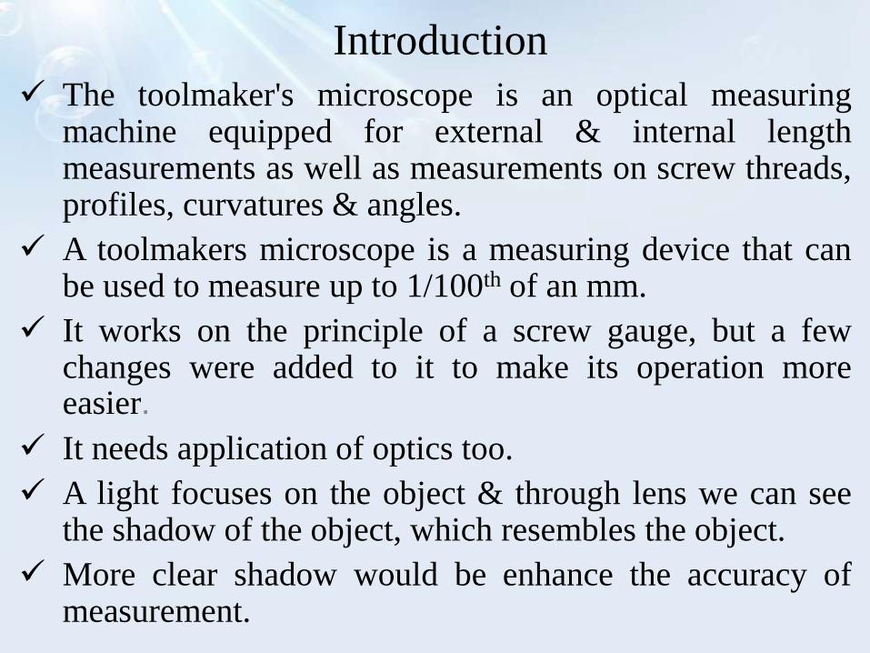
The toolmaker's microscope is an optical measuringmachine equipped for external & internal lengthmeasurements as well as measurements on screw threads,profiles, curvatures & angles.
A toolmakers microscope is a measuring device that canbe used to measure up to 1/100th of an mm.
It works on the principle of a screw gauge, but a fewchanges were added to it to make its operation moreeasier.
It needs application of optics too.
A light focuses on the object & through lens we can seethe shadow of the object, which resembles the object.
More clear shadow would be enhance the accuracy ofmeasurement.

Principle of Measurement
A ray of light from a light source is reflected by a mirrorthrough 90˚.
It then passes through a transparent glass plate.
A shadow image of the outline or counter of theworkspaces passes through the objective of the opticalhead & is projected by a system of three prisms to aground glass screen.
Observations are made through an eyepiece.
Measurements are made by means of cross lines engravedon the ground glass screen.
The screen can be rotated through 360˚ the angle ofrotation is read through an auxiliary eyepiece.
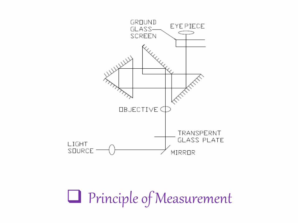
Principle of Measurement
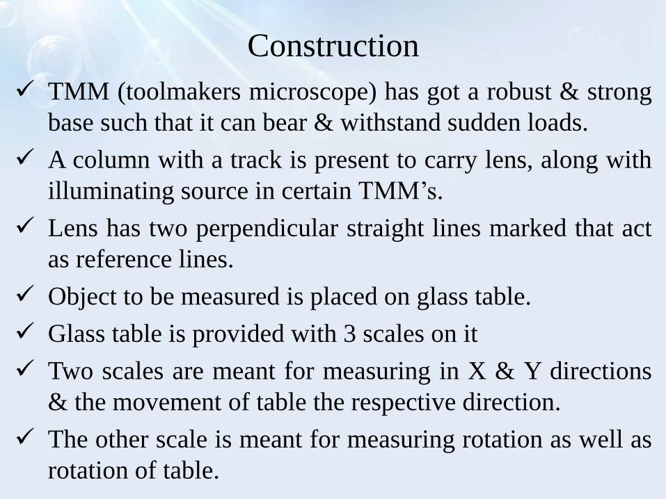
Construction
TMM (toolmakers microscope) has got a robust & strong
base such that it can bear & withstand sudden loads.
A column with a track is present to carry lens, along with
illuminating source in certain TMM’s.
Lens has two perpendicular straight lines marked that act
as reference lines.
Object to be measured is placed on glass table.
Glass table is provided with 3 scales on it
Two scales are meant for measuring in X & Y directions
& the movement of table the respective direction.
The other scale is meant for measuring rotation as well as
rotation of table.
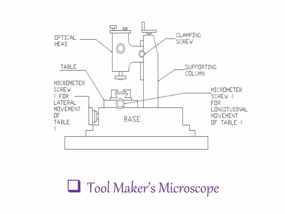
Tool Maker’s Microscope
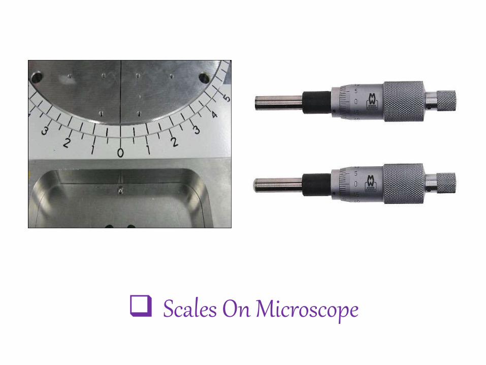
Scales On Microscope
Working
• The component being measured is illuminated by the
through light method.
• A parallel beam of light illuminates the lower side of
work-piece which is then received by the objective lens in
its way to a prism that deflects the light rays in the
direction of the measuring ocular & the projection screen.
• The direction of illumination can be tilted with respect to
the work-piece by tilting the measuring head & the whole
optical system.
• This inclined illumination is necessary in some cases as in
screw thread measurements.
Application
Length measurement in Cartesian & polar co-ordinates.
Angle measurements of tools.
Thread measurements i.e., profile major & minor
diameters, height of lead, thread
angle, profile position with respect to the thread axis & the
shape of thread.
Comparison between centers & drawn patterns & drawing
of projected profiles.
Used for measuring the shape of different components like
the template, formed cutter, milling cutter, punching die,
and cam