torque table listing - new-line
TRANSCRIPT

Industry Flows Through Us [email protected]
molded PTFE expansion joints440SERIES
The PROCO Series 440 PTFE Molded Expansion Joints are used for corrosive applica-tions found in: Chemical-Petrochemical, Industrial Process Piping Systems, PowerGeneration Plants, Pulp/Paper Plants, Water-Wastewater Sewage and Pollution Con-trol Systems where metallic joints/lap joints or PTFE & FEP-lined rubber expansionjoints may have been previously used or specified. Specify PROCO Series 440 expan-sion joints for installation between anchor points or next to mechanical equipmentsuch as: Absorption Machines, Blowers, Chillers, Fans, Graphite Heat Exchangers,Glass Lined Vessels, Pumps, and Exotic Alloy/Plastic/Glass Lined Piping Systems.The Series 440 expansion joints are designed to: (1) Absorb Pipe Movements/Stress,(2) Reduce System Noise, (3) Reduce Mechanical Vibration, (4) Compensate Align-ment/Offset, (5) Eliminate Electrolysis, (6) Protect against Start-up/Surge Forces. Ourhistory in the manufacture of expansion joint products dates back to 1930. When anengineered solution is needed to solve a piping problem, call PROCO.Engineered For Your Application. The PROCO Series 440 PTFE expansion joints areavailable in 2, 3, and 5 convolutions. Each convolution profile offers different overalllengths (face-to-face dimensions), movements and pressure/temperature rating to fitthe required specification. Available styles include:
• Style 442-BD: Features two convolutions for minimal movements, higher pressure/temperature ratings and short face-to-face opening requirements. Style 442-BD sizesrange from 1" to 24" diameter. (See Table 1)• Style 443-BD: Features three convolutions and is designed for moderate movementand ease of system installation. Style 443-BD sizes range from 1" to 24" diameter. (SeeTable 2)• Style 445-BD: Features five convolutions, and is designed for maximum movements,low pressure/temperature ranges, vibration reduction and greater face-to-face lengths.Style 445-BD sizes range from 1" to 20" diameter. (See Table 3)• Style 440-BE: Features varying Neutral Lengths with Styles’ 440-BD Limit Bolts.(See Table 4)
Absorbs Pipe-Wall and Fluid-Borne Noise. The quiet operating PROCO Series 440 PTFEexpansion joints are a replacement for “sound transmitting” metallic/lap joints. Pipe Wallsound loses energy and is absorbed as the noise carried by the piping enters and exits thePTFE section. Fluid-borne noise is absorbed by the volumetric expansion (breathing of theconnector). This action cushions water hammer and smoothes out pumping impulses.Isolates Vibration and Motion. PROCO Series 440 PTFE expansion joints should beinstalled immediately after and ahead of equipment generating vibration in order toisolate the rotating/vibrating equipment from the rest of the piping system. For opti-mum performance, the PROCO Series 440 PTFE expansion joints should be installedhorizontally to the shaft. Vertical and perpendicular installations are also acceptable asthese expansion joints will accept axial, lateral and angular movements as well as vi-bration. Note: For maximum vibration transmission reduction, the pipe section beyondthe PTFE expansion joints must be anchored or sufficiently rigid.Reduces System Stress and Strain. Rigid attachment of piping to critical or mechanicalequipment can produce excessive loading. Thermal or mechanically created strain-stress-shock are cushioned and absorbed with the installation of a flexible, low spring rate, PROCOSeries 440 PTFE expansion joint. The PROCO Series 440 PTFE expansion joint adds aflexible component to the system that automatically self-corrects for misalignment createdby structural movements caused by settling, pipe expansion or ground shifts.
Tested Force Pound and Spring Rate Tables. At PROCO we have machine tested nearlyevery size of the Series 440 PTFE expansion joints for Axial and Lateral Spring Ratesand have provided Thrust/Force factors so designers can properly design system re-straints. It should be noted that the PROCO Series 440 PTFE expansion joints are inaccordance with the performance characteristics of the Fluid Sealing Association’s Non-Metallic Expansion Joint Division.Superior “Flex Life” and Strength. The PROCO Series 440 PTFE expansion joints arecontour molded from extruded tubing providing superior “Flex Life” and Strength. Utiliz-ing TEFLON® T-62 resins from DuPont, the PROCO Series 440 PTFE expansion jointsprovide dramatically more cycle life than that of PFA or FEP.Flange and Limit Bolts. All PROCO Series 440 PTFE expansion joint flange configura-tions are coated with a rust inhibitive primer to prevent corrosion and are dimension-ally tapped to ANSI 125/150# Standards. Hole drilling on center line, other drillingstandards, or other flange materials, such as 316 stainless, 304 stainless, or EpoxyCoated flanges are available on special order. In addition, all PROCO Series 440 PTFEexpansion joints are supplied with factory set limit bolts to prevent over-extensionduring operation.Chemical Service Capability at Minimal Cost. Expensive, exotic metal, PTFE or FEPlined rubber expansion joints for severe chemical service can be replaced with the lowcost PROCO Series 440 PTFE expansion joints. The PTFE bellows are van stoned to theflanges which allows all wetted surfaces to come in contact with only the PTFE mate-rial. Specify the PROCO Series 440 PTFE expansion joints where high temperaturescoupled with lower pressures or lower temperatures coupled with higher pressuresare proposed. The PROCO Series 440 PTFE offers the lowest cost expansion joint thatis impervious to chemical attack. Use the PROCO “Chemical to Elastomer Guide” forreference on chemical compatibility.Services and Locations. PROCO Series 440 PTFE Expansion Joints have been sup-plied and successfully used by a range of customers worldwide in the process indus-tries for use in both organic and inorganic chemical processing and production, in-cluding such demanding applications as agrochemical and pharmaceutical chemicalproduction, acid processing and food manufacture.Information • Ordering • Pricing • Delivery. Day or night, weekends and holidays…thePROCO phones are monitored 24 hours around the clock. When you have a question,you can call us.
Toll-Free Phone . . . . . . . 800 / 344-3246 USA/CANADAInternational Calls . . . . . 209 / 943-6088Fax . . . . . . . . . . . . . . . . . 209 / 943-0242Email . . . . . . . . . . . . . . . [email protected] . . . . . . . . . . . . . www.procoproducts.com
Weekday office hours are 5:30 a.m. to 5:15 p.m. Pacific Time.
Protecting Piping And EquipmentSystems From Stress/Motion
© PROCO PRODUCTS, INC.Rev. 4 9/10
Installation Instructions for Series 440 PTFE Expansion Joints
ENGINEERING DESIGN NOTES:1. It is essential that piping system thrusts be calculated to ensure cor-rect sizing of anchors and pipe supports, plus ensure that allowable thrustforces on adjacent mechanical and rotating equipment are not exceeded.Please use the following formulas:
Tp = P • Tf
Tp is the pressure thrust (lbf), P is the system operating pressure (Psig)and T1 is the thrust factor (or bellows effective area [in2]). The pressurethrust, Tp, will act in the axial direction and must be added to the axialspring force (Fx•∆x) to give the total axial reaction force, Rx.
Rx = Tp + (Fx • ∆x)
Rx is the pipe support reaction force (lbf), Tp is the pressure thrust (lbf),Fx is the axial spring force of the unit and ∆x is the expected or designedaxial movement of the unit (See Tables 1–3).
2. It should be noted that axial spring rate values found in Tables 1through 3 are based on an ambient temperature (70°F) and will decreaseas the system temperature rises. In addition, spring rates decrease overtime due to thermoplastic creep if units are operated under pressure.
1. Service Conditions: Make sure the expansion joint ratings for tempera-ture, vacuum, spring rates and movements match the system requirements.Contact PROCO if the system requirements exceed those of the expansionjoint selected.2. Alignment: PROCO Series 440 PTFE expansion joints are not designedto make up for piping misalignment error. Pipe misalignment should be nomore than 1/8" in any direction. Misalignment of an expansion joint willreduce the rated movements and can cause stress of material properties,thus causing reduced service life.3. Limit Bolts: Limit bolts are factory set at the maximum allowabletravel position to prevent over extension. Do not remove or alter nuts atany time. Damage or personal injury can result due to changes in limitbolt settings.4. Anchoring: Solid anchoring is required whenever the pipeline changesdirection. PROCO Series 440 PTFE expansion joints should be located asclose as possible to these anchor points. If an anchoring system is notused, any associated pressure thrust can cause excessive movement, ul-timately damaging the expansion joint. (It should be noted that the at-tached limit bolts/cables are designed to limit movement and are notdesigned to handle pressure thrust.)5. Pipe Support: Piping must be supported by hangers or anchors soexpansion joints do not carry any pipe weight.6. Personnel Protection: It is strongly recommended that spray shieldsbe used for all hazardous service to protect against serious personalinjury in the event of expansion joint failure. (Contact PROCO for sprayshield information.)7. Installation:
a. Store expansion joints with wood covers in-place to protect PTFE flangesurfaces from damage until ready to install.
b. Check to make sure PTFE surfaces are clean and free of foreign sedi-ment. Remove nicks, burrs and deep scratches with a fine emery cloth.If surface irregularities cannot be completely removed, install a PTFEenvelope-type gasket to obtain an adequate seal.c. Install the PROCO Series 440 PTFE expansion joints to the prescribedneutral lengths. If expansion joints are used in high temperature pro-cesses, it is recommended that units be installed at/near the extendedvalues. For cold process installations, expansion joints should be in-stalled in a nearly compressed length. These settings will enable theexpansion joint to realize full travel capabilities. (See appropriate Tablesfor Neutral Lengths.)d. Thread installation bolts from mating flange side to prevent possibledamage to PTFE elements. Extend bolts beyond the expansion joint flangeby no more than 1–2 threads. Nuts are not necessary due to threadedflange holes.e. Tighten flange bolts with a torque wrench. Tighten in an alternatecrossing pattern in 20% increments until 80% of final bolt torques havebeen achieved. Tighten to final torque values (listed in Torque Table List-ing) in a clockwise fashion around the flange to ensure bolts carry equalstress burdens.f. Re-tighten bolts after first cycle of operation. Re-tighten as necessaryafter every planned maintenance shutdown. All bolts should be re-torquedto the above listed values.
8. Operations: After expansion joints are installed, it may be necessary toair blast the exterior to remove foreign debris, such as metal chips, frombetween the convolutions. The expansion joint should then be coveredwith a shield to protect from damage and foreign debris during operation.(Note: Do not weld in immediate vicinity of expansion joint unless it isproperly protected.)
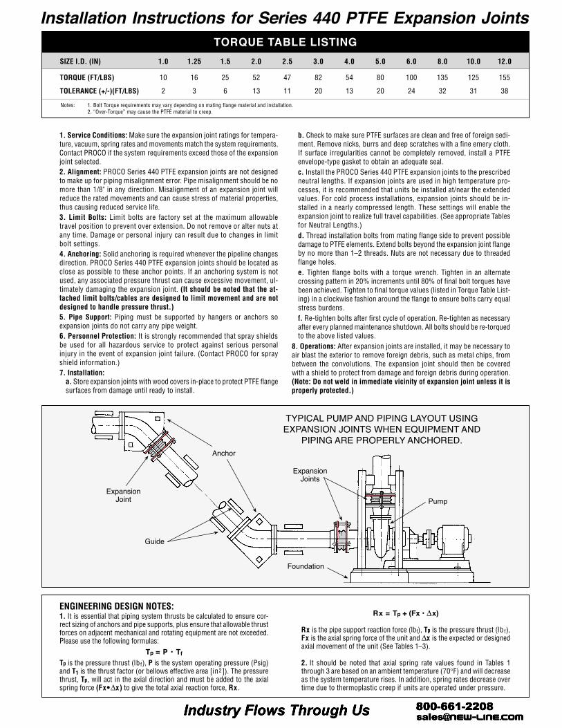
Pump
Foundation
Anchor
ExpansionJoints
Guide
ExpansionJoint
TYPICAL PUMP AND PIPING LAYOUT USINGEXPANSION JOINTS WHEN EQUIPMENT AND
PIPING ARE PROPERLY ANCHORED.
SIZE I.D. (IN) 1.0 1.25 1.5 2.0 2.5 3.0 4.0 5.0 6.0 8.0 10.0 12.0
TORQUE (FT/LBS) 10 16 25 52 47 82 54 80 100 135 125 155
TOLERANCE (+/-)(FT/LBS) 2 3 6 13 11 20 13 20 24 32 31 38
TORQUE TABLE LISTING
Notes: 1. Bolt Torque requirements may vary depending on mating flange material and installation.2. “Over-Torque” may cause the PTFE material to creep.