total sliding mode position control of a linear variable ... · a linear variable reluctance motor....
TRANSCRIPT
1
Ruchao Pupadubsin Industrial and Control Automation (ICA) Laboratory
NECTEC
NECTEC ACE 2010 Pathumthani, Thailand
September 23-24, 2010
Total Sliding Mode Position Control of
a Linear Variable Reluctance Motor
2
Contents
� Introduction
� Structure and Principle of Linear
Variable Reluctance (LVR) Motor
� Position Control
� Experimental Results
� Conclusions/Future work
“Total Sliding Mode Position Control of a Linear Variable Reluctance Motor”

3
�� Applications of linear motion
automation process
Transportation
Elavator
Material handling
Assembly Payload
Applications
Introduction
“Total Sliding Mode Position Control of a Linear Variable Reluctance Motor”

4
Introduction
�Technologies for linear motion
– Rotary motors with mechanical transmissions
Lead screw
Tooth belt Disadvantages
Mechanical transmission losses, high
maintenance, mechanical limitations on
acceleration and velocity, limited accuracy
Advantages
Simplicity for implementation, lower
cost, more widely use
“Total Sliding Mode Position Control of a Linear Variable Reluctance Motor”

5
Introduction
�Technologies for linear motion
– Linear motors (direct drive): permanent magnet, reluctance, induction, DC
Advantages
Less friction, higher accuracy, no
backlash, low maintenance, longer
lifetime
Disadvantages
Higher cost, high maintenance (LPM)
“Total Sliding Mode Position Control of a Linear Variable Reluctance Motor”

6
Introduction
�Goals of paper
2.2. Implement the developed position
control, which is based on a simplified
sinusoidal flux model for LVR motor
1.1. Develop a simple position control
with good performance for LVR motor
“Total Sliding Mode Position Control of a Linear Variable Reluctance Motor”

7
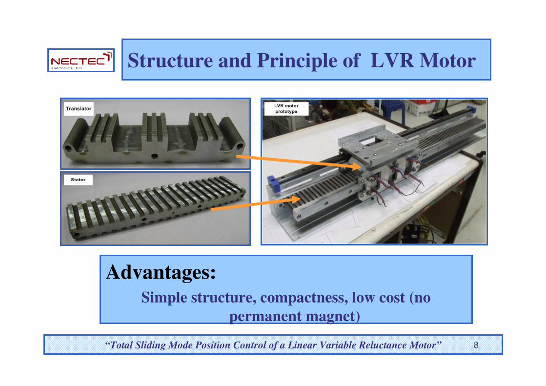
Structure and Principle of LVR Motor
� Two E-cores moving along the stator
� Motor windings are installed on each side of the E-cores
� Strong magnetic coupling between phases
� Symmetric structure with zero normal force when balanced
“Total Sliding Mode Position Control of a Linear Variable Reluctance Motor”
8
Structure and Principle of LVR Motor
Advantages:
Simple structure, compactness, low cost (no
permanent magnet)
“Total Sliding Mode Position Control of a Linear Variable Reluctance Motor”

9
Structure and Principle of LVR Motor
� Phase voltage equations of the LVR motor in the dq0
domain
� Force function of the LVR motor
“Total Sliding Mode Position Control of a Linear Variable Reluctance Motor”

10
Structure and Principle of LVR Motor
� Mechanical dynamic equation of the LVR motor
M : Moving mass
B : Viscous friction coefficient
FL : External force
“Total Sliding Mode Position Control of a Linear Variable Reluctance Motor”
LF Mx Bx F= + +�� �

11
Position Control
� Design for high precision position control
for manufacturing automation applications
� Use the dq0 theory of classical synchronous
reluctance motors
– Sinusoidal reluctance/inductance
approximation
“Total Sliding Mode Position Control of a Linear Variable Reluctance Motor”
12
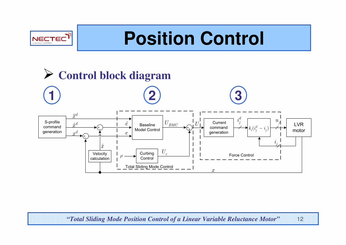
� Control block diagram
1 2 3
“Total Sliding Mode Position Control of a Linear Variable Reluctance Motor”
Current
command
generation
LVR
motor( )di j jk i i−
ji
x
x�
Udji ju
dx
dx�
dx��
Velocity
calculation
+-
+-
Curbing
Control
e
e�
cU
S-profile
command
generation
BMCUBaseline
Model Control
ρ
Total Sliding Mode Control
Force Control
++
Position Control
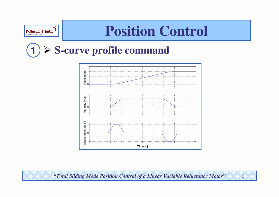
13
Position Control
�� S-curve profile command1
Ref. [15]
“Total Sliding Mode Position Control of a Linear Variable Reluctance Motor”

14
� Total Sliding Mode Control2
1 2
1- ,n n
BC C
M M= =
“Total Sliding Mode Position Control of a Linear Variable Reluctance Motor”
LF Mx Bx F= + +�� �
1 2( ) ( ) ( ) ( )n nx t C x t C U t W t= + +�� �
( ) lumped uncertainty
U F
W t
=
=
Position Control

15
� Total Sliding Mode Control2
UBMC
: Baseline model control
Uc
: Curbing control
Position Control
“Total Sliding Mode Position Control of a Linear Variable Reluctance Motor”
BMC cU U U= +

16
� Total Sliding Mode Control
:Baseline model control
2
1st term to compensate nonlinear effects
2nd term to determine system performance
Position Control
“Total Sliding Mode Position Control of a Linear Variable Reluctance Motor”
1 12 1 2BMC n n n p d
U C C x C x k e k e− − = − + + +
� �� �

17
� Total Sliding Mode Control
:Curbing control
2
To eliminate the perturbation and uncertainty effects
Position Control
“Total Sliding Mode Position Control of a Linear Variable Reluctance Motor”
12( ) ( ) sgn( ( ))c nU t t C S tρ−= −
( )W t ρ<
The selection of ρ affects the chattering phenomena
and system stability performance

18
Position Control
� Desired phase current command3
� Constant parameters
Ref. [7]
“Total Sliding Mode Position Control of a Linear Variable Reluctance Motor”
1 1 1
2 2 2
3 33
cos sin1
cos sinsgn( )
cos sin
dd
dd
d
i x xF
i x xF
x xiγ
− = − −

19
Position Control
� Current control3
- Desired phase voltage
ki= Current control parameter
“Total Sliding Mode Position Control of a Linear Variable Reluctance Motor”
( )dj i j ju k i i= −

20
Position Control� Experimental setup
- dSPACE controller board
- Three phase power inverter
- 14kg payload
- Two desired trajectories for experimental test
- Short-distance profile: 400 µm
- Long-distance profile: 10 cm
- Two controllers for experimental test
- Input-output linearization control [8]
- Total sliding mode control
“Total Sliding Mode Position Control of a Linear Variable Reluctance Motor”

21
Position Control� Experimental setup
“Total Sliding Mode Position Control of a Linear Variable Reluctance Motor”
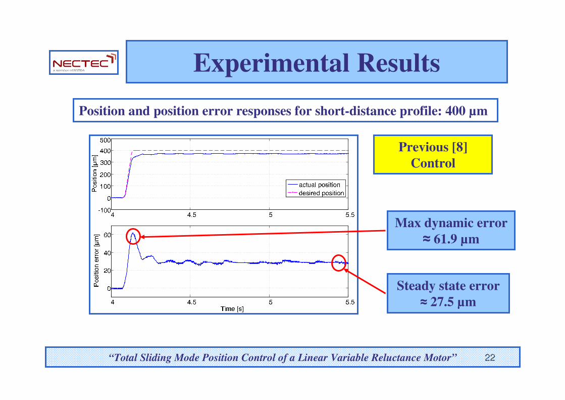
22
Experimental Results
Position and position error responses for short-distance profile: 400 µm
Max dynamic error
≈ 61.9 µm
Steady state error
≈ 27.5 µm
“Total Sliding Mode Position Control of a Linear Variable Reluctance Motor”
Previous [8]
Control

23
Positio
n [µm
]P
ositio
n e
rror [µ
m]
Experimental Results
Position and position error responses for short-distance profile: 400 µm
Max dynamic error
≈ 31.7 µm
Steady state error
≈ 10 µm
“Total Sliding Mode Position Control of a Linear Variable Reluctance Motor”
Total Sliding
Mode Control

24
Experimental Results
Position and position error responses for long-distance profile: 10 cm
Max dynamic error
≈ 331.4 µm
Steady state error
≈ 22 µm
“Total Sliding Mode Position Control of a Linear Variable Reluctance Motor”
Previous [8]
Control
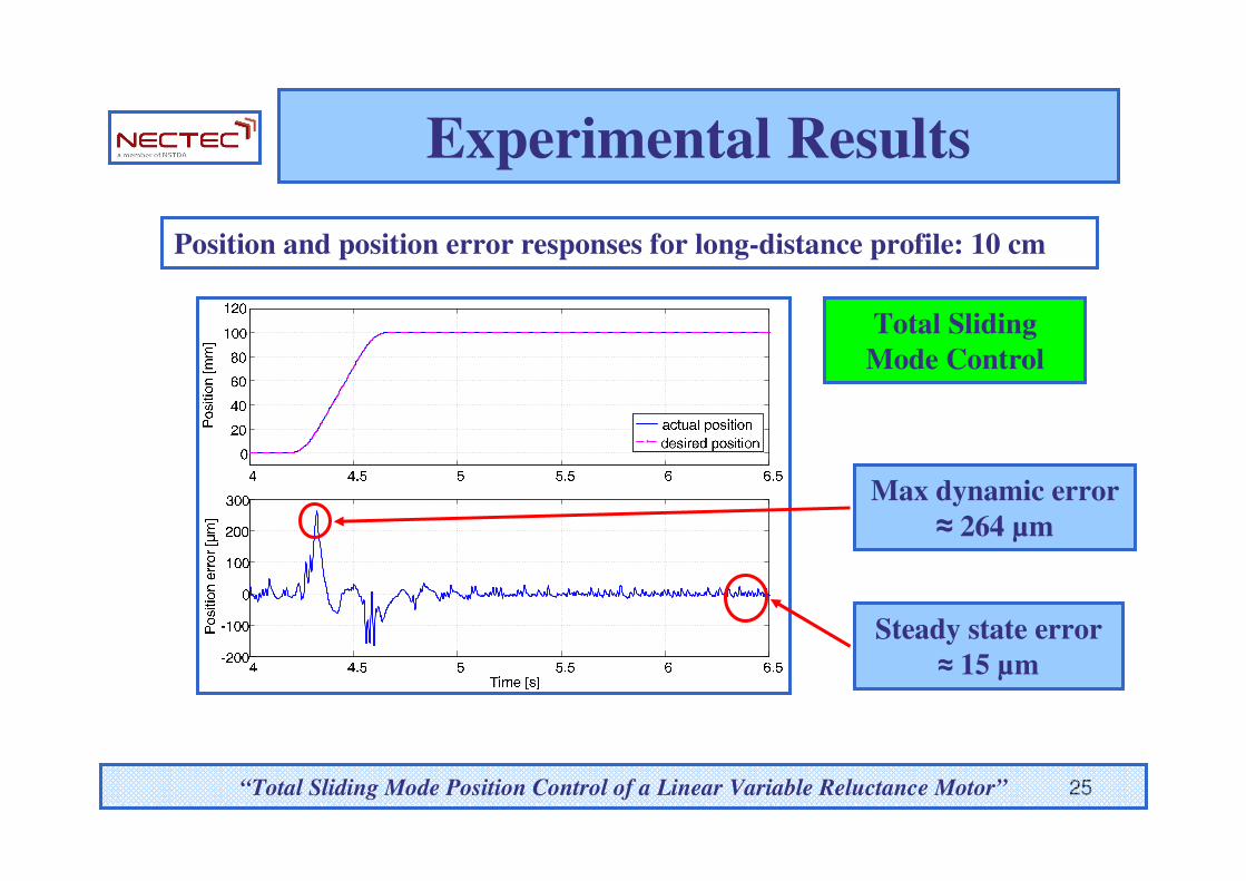
25
Experimental Results
Position and position error responses for long-distance profile: 10 cm
Max dynamic error
≈ 264 µm
Steady state error
≈ 15 µm
“Total Sliding Mode Position Control of a Linear Variable Reluctance Motor”
Total Sliding
Mode Control
26
Conclusions/Future work
�Advantages
- Simple and computationally efficient for
implementation
- System robustness to parameter variations
� Disadvantages
- Chattering phenomena problem
- Future work to reduce chattering phenomena to achieve higher accuracy for high-precision application
“Total Sliding Mode Position Control of a Linear Variable Reluctance Motor”

27
Thank You
“Total Sliding Mode Position Control of a Linear Variable Reluctance Motor”