touching the earth lightly: the u.s. 20 iowa river bridge the earth lightly: the u.s. 20 iowa river...
TRANSCRIPT
PDHonline Course C684 (2 PDH)
Touching the Earth Lightly:
The U.S. 20 Iowa River Bridge
Instructor: J.M. Syken
2014
PDH Online | PDH Center
5272 Meadow Estates Drive
Fairfax, VA 22030-6658
Phone & Fax: 703-988-0088
www.PDHonline.org
www.PDHcenter.com
An Approved Continuing Education Provider
1
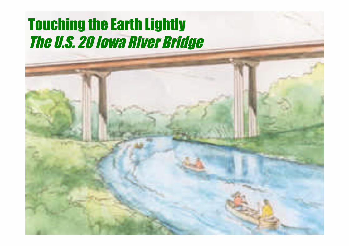
Touching the Earth LightlyThe U.S. 20 Iowa River Bridge

2
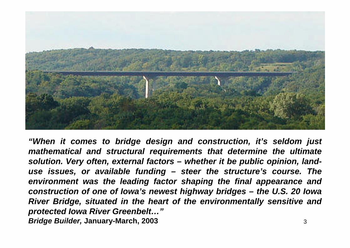
A Highway Runs Through It
3
“When it comes to bridge design and construction, it’s seldom justmathematical and structural requirements that determine the ultimatesolution. Very often, external factors – whether it be public opinion, land-use issues, or available funding – steer the structure’s course. Theenvironment was the leading factor shaping the final appearance andconstruction of one of Iowa’s newest highway bridges – the U.S. 20 IowaRiver Bridge, situated in the heart of the environmentally sensitive andprotected Iowa River Greenbelt…”Bridge Builder, January-March, 2003
4
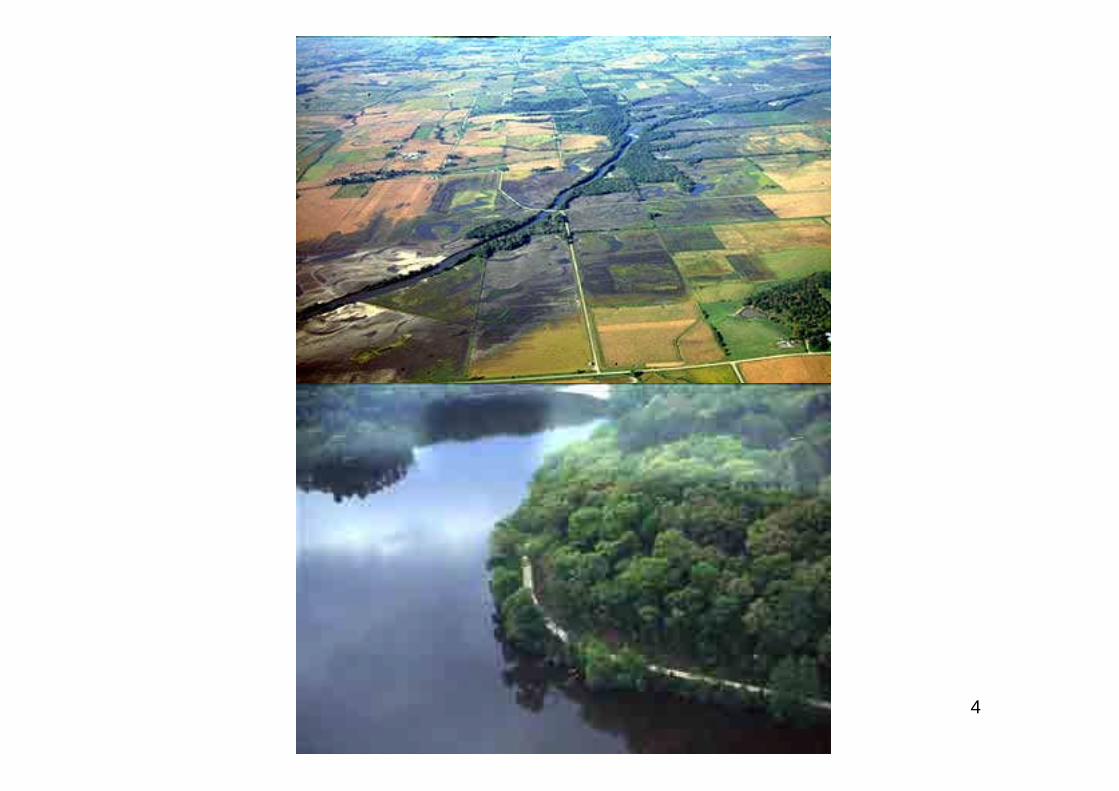
5
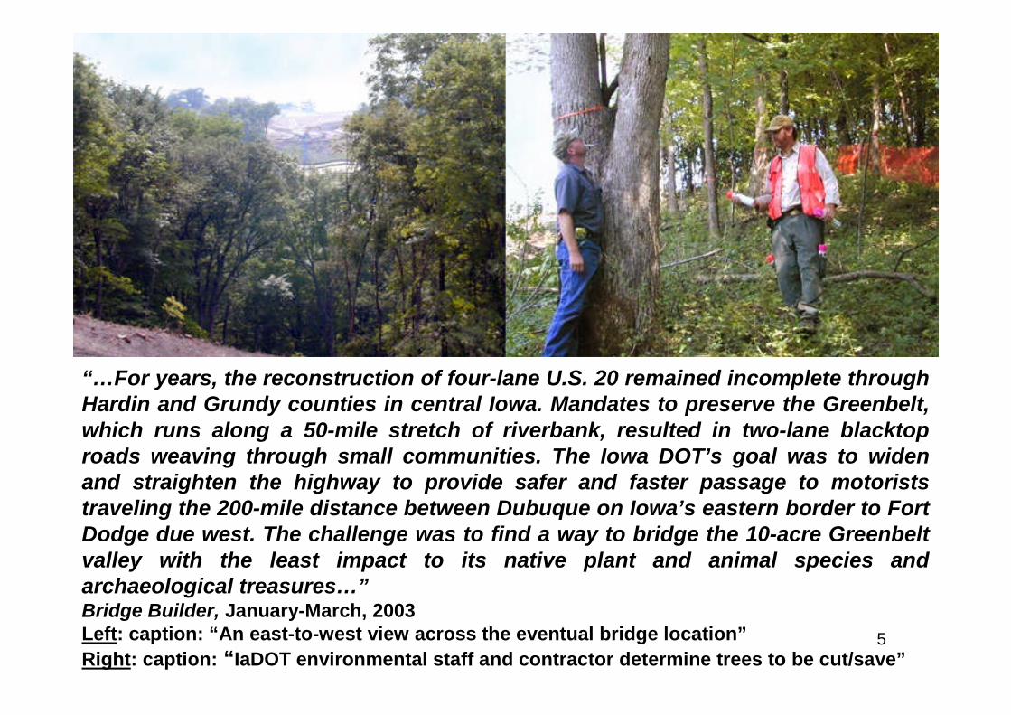
“…For years, the reconstruction of four-lane U.S. 20 remained incomplete throughHardin and Grundy counties in central Iowa. Mandates to preserve the Greenbelt,which runs along a 50-mile stretch of riverbank, resulted in two-lane blacktoproads weaving through small communities. The Iowa DOT’s goal was to widenand straighten the highway to provide safer and faster passage to motoriststraveling the 200-mile distance between Dubuque on Iowa’s eastern border to FortDodge due west. The challenge was to find a way to bridge the 10-acre Greenbeltvalley with the least impact to its native plant and animal species andarchaeological treasures…”Bridge Builder, January-March, 2003Left: caption: “An east-to-west view across the eventual bridge location”
Right: caption: “IaDOT environmental staff and contractor determine trees to be cut/save”
6
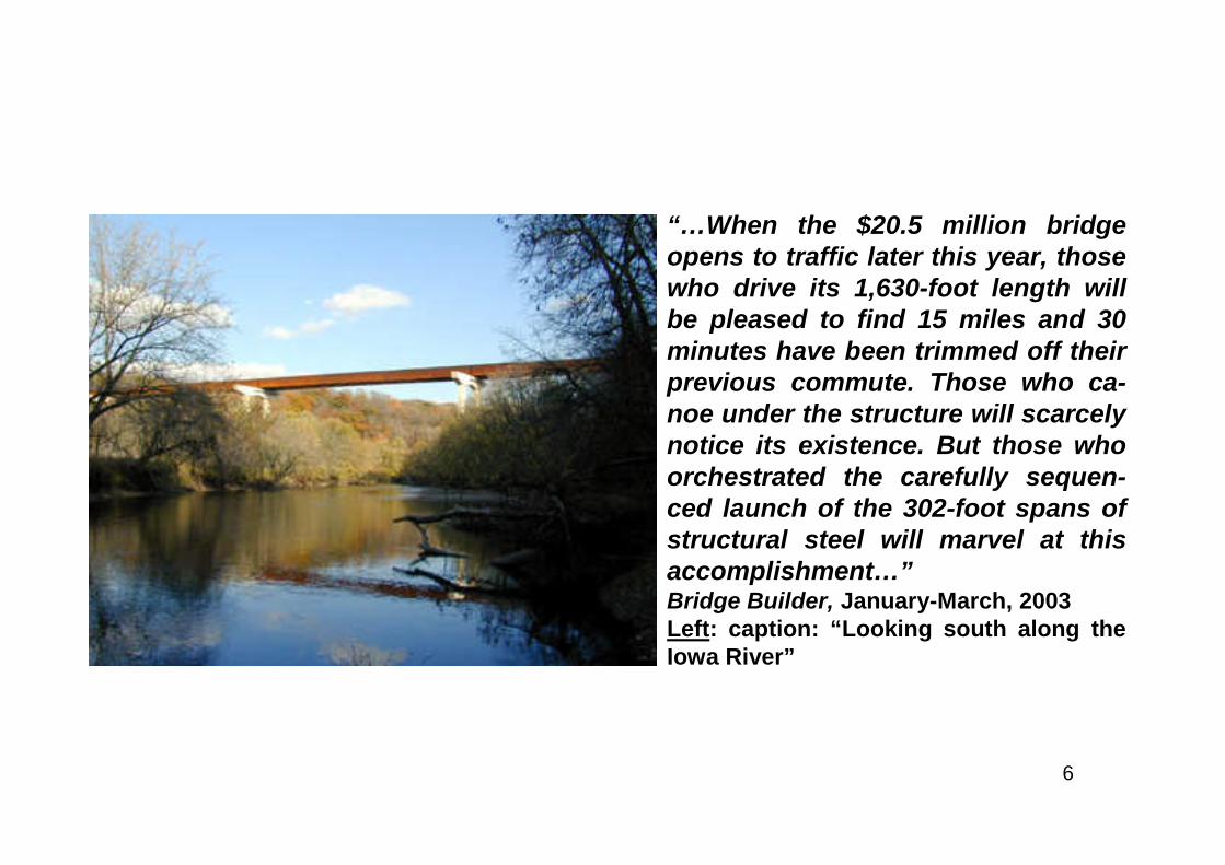
“…When the $20.5 million bridgeopens to traffic later this year, thosewho drive its 1,630-foot length willbe pleased to find 15 miles and 30minutes have been trimmed off theirprevious commute. Those who ca-noe under the structure will scarcelynotice its existence. But those whoorchestrated the carefully sequen-ced launch of the 302-foot spans ofstructural steel will marvel at thisaccomplishment…”Bridge Builder, January-March, 2003Left: caption: “Looking south along theIowa River”
7
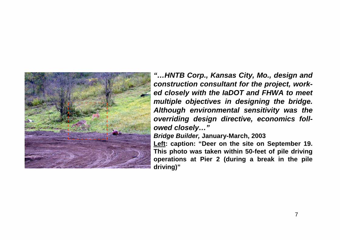
“…HNTB Corp., Kansas City, Mo., design andconstruction consultant for the project, work-ed closely with the IaDOT and FHWA to meetmultiple objectives in designing the bridge.Although environmental sensitivity was theoverriding design directive, economics foll-owed closely…”Bridge Builder, January-March, 2003Left: caption: “Deer on the site on September 19.This photo was taken within 50-feet of pile drivingoperations at Pier 2 (during a break in the piledriving)”
8
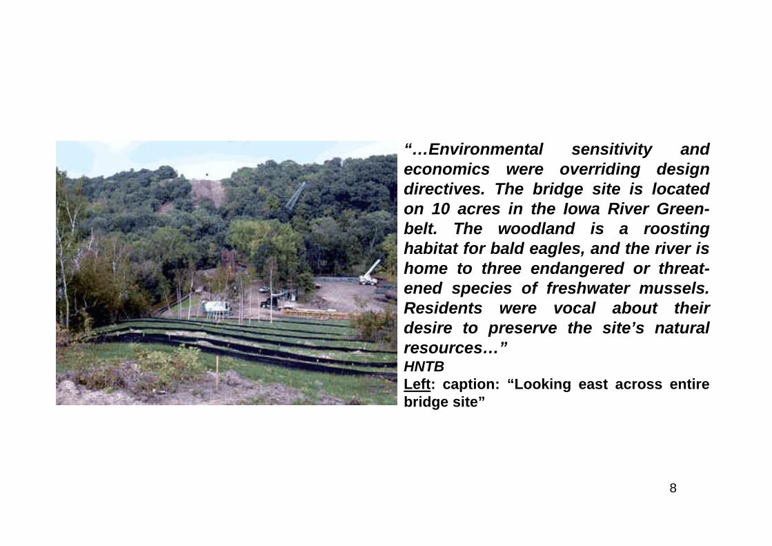
“…Environmental sensitivity andeconomics were overriding designdirectives. The bridge site is locatedon 10 acres in the Iowa River Green-belt. The woodland is a roostinghabitat for bald eagles, and the river ishome to three endangered or threat-ened species of freshwater mussels.Residents were vocal about theirdesire to preserve the site’s naturalresources…”HNTBLeft: caption: “Looking east across entirebridge site”

9
Ecological Design
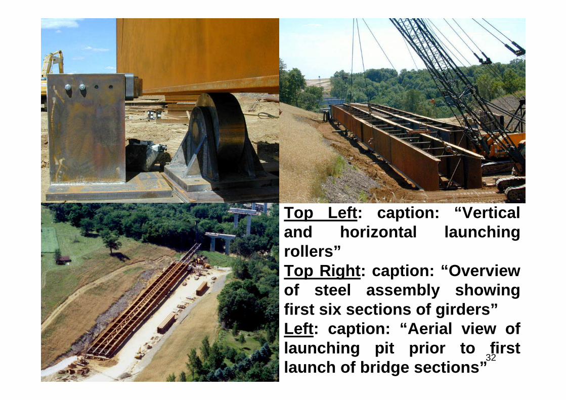
10
“…Upon final selection of the site in 1996 (the culmination ofmore than 25 years of planning), HNTB studied six bridgedesigns ranging from concrete and steel arches to concretebox girders to steel I-girders. Multiple erection methods wereevaluated as well. Because IaDOT was not seeking asignature bridge design, several options were quicklyeliminated. After evaluating each for cost feasibility, en-vironmental impact, and aesthetic appeal, HNTB rec-ommended a launched steel I-girder design, with longerspans to reduce to reduce the number of piers needed andminimize visual obstructions at river level. Weathering steelmaterial was selected for two reasons: It blends seamlesslyinto the natural surroundings and eliminates the need forfuture painting…”Bridge Builder, January-March, 2003
11
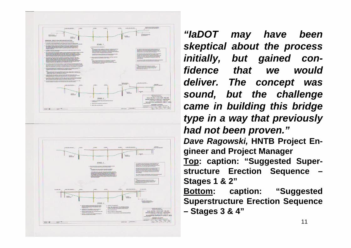
“IaDOT may have beenskeptical about the processinitially, but gained con-fidence that we woulddeliver. The concept wassound, but the challengecame in building this bridgetype in a way that previouslyhad not been proven.”Dave Ragowski, HNTB Project En-gineer and Project ManagerTop: caption: “Suggested Super-structure Erection Sequence –Stages 1 & 2”Bottom: caption: “SuggestedSuperstructure Erection Sequence– Stages 3 & 4”
12
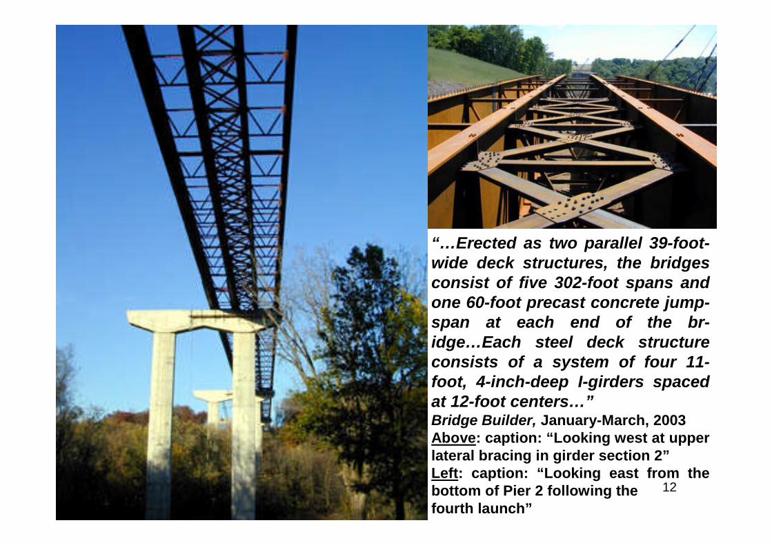
“…Erected as two parallel 39-foot-wide deck structures, the bridgesconsist of five 302-foot spans andone 60-foot precast concrete jump-span at each end of the br-idge…Each steel deck structureconsists of a system of four 11-foot, 4-inch-deep I-girders spacedat 12-foot centers…”Bridge Builder, January-March, 2003Above: caption: “Looking west at upperlateral bracing in girder section 2”Left: caption: “Looking east from thebottom of Pier 2 following thefourth launch”
13
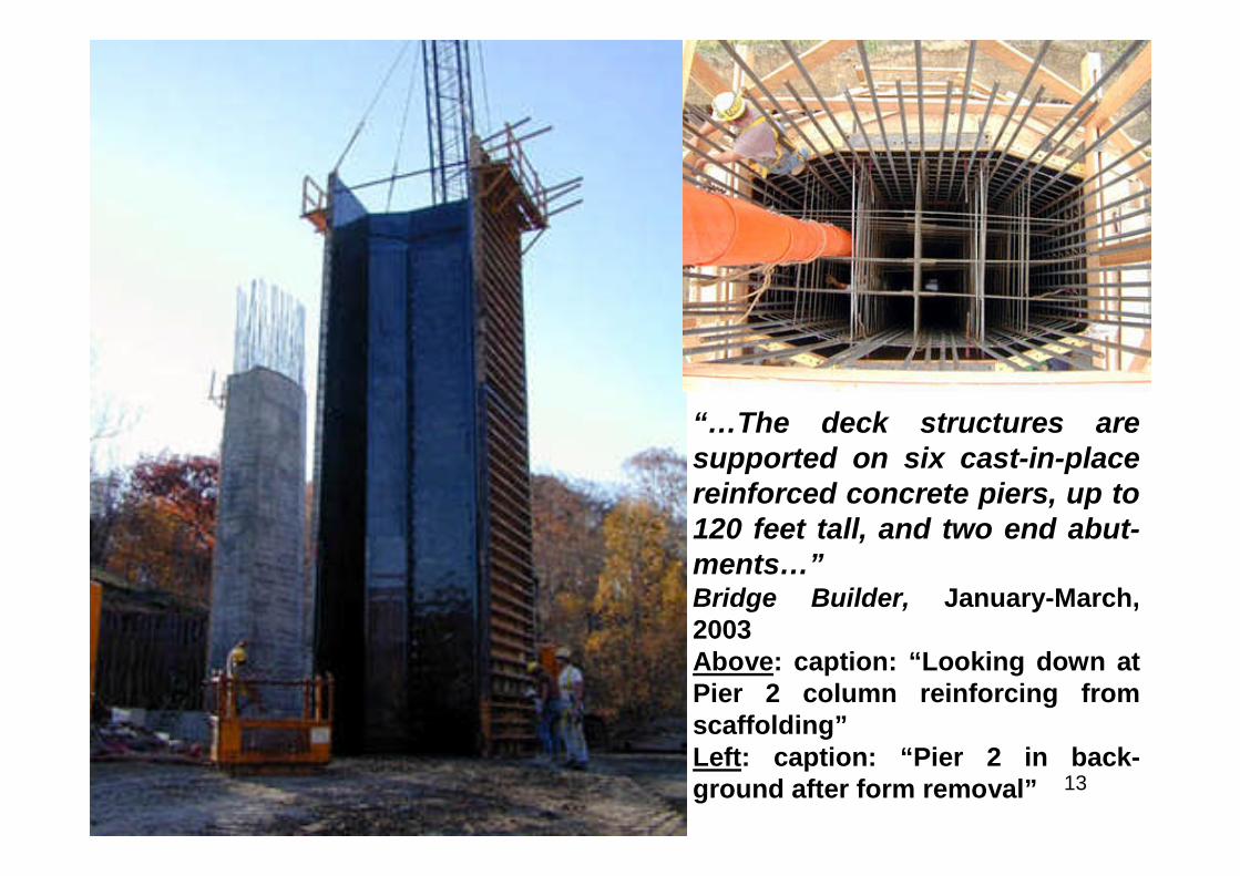
“…The deck structures aresupported on six cast-in-placereinforced concrete piers, up to120 feet tall, and two end abut-ments…”Bridge Builder, January-March,2003Above: caption: “Looking down atPier 2 column reinforcing fromscaffolding”Left: caption: “Pier 2 in back-ground after form removal”
14
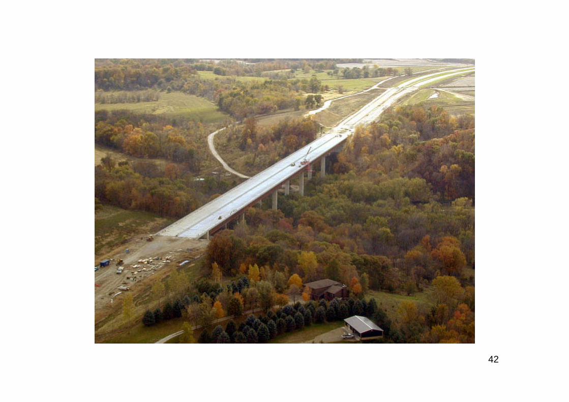
“…To protect three small mussel species, the project teamhad to keep construction equipment out of the river andconstruct a containment system to prevent fluids in the river,including accidental fuel spills, hydraulic oil from machineryhoses, and even natural water that emerged from con-structing drilled shaft foundations through lenses of waterabove the rock formations. Also, a number of different zoneson-site required clearing procedures and environmentalprotection. The contractor had to construct minimal accesspaths into the valley, which were removed and restored aftercompletion. A temporary crane mat was constructed in theeast river bottom above the high-water elevation to minimizethe risk of damage to both the environment and thecontractor’s equipment…”Bridge Builder, January-March, 2003
15
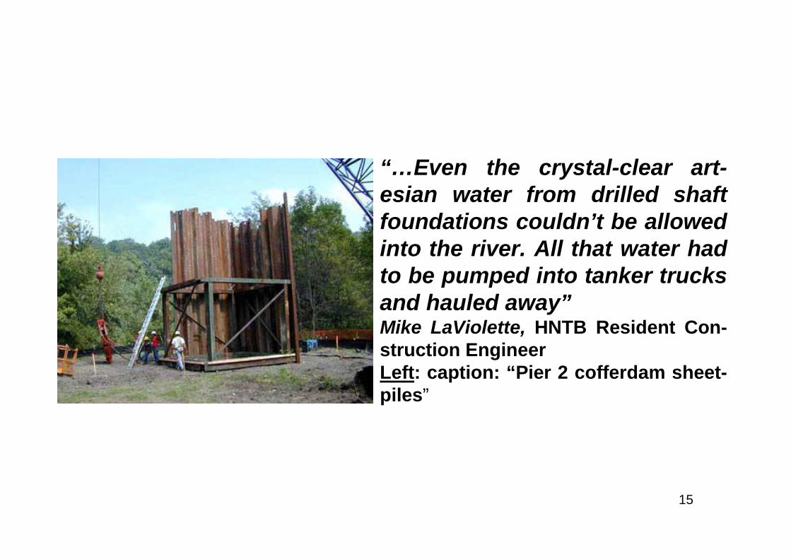
“…Even the crystal-clear art-esian water from drilled shaftfoundations couldn’t be allowedinto the river. All that water hadto be pumped into tanker trucksand hauled away”Mike LaViolette, HNTB Resident Con-struction EngineerLeft: caption: “Pier 2 cofferdam sheet-piles”
16
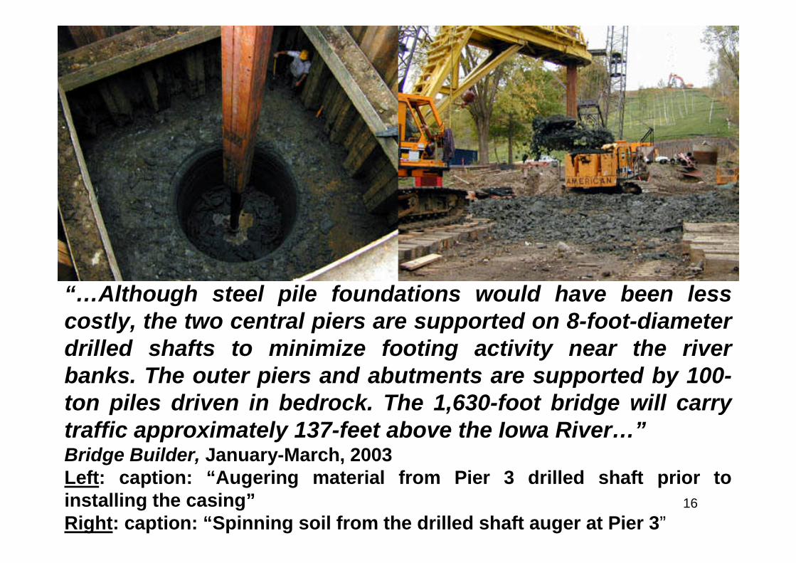
“…Although steel pile foundations would have been lesscostly, the two central piers are supported on 8-foot-diameterdrilled shafts to minimize footing activity near the riverbanks. The outer piers and abutments are supported by 100-ton piles driven in bedrock. The 1,630-foot bridge will carrytraffic approximately 137-feet above the Iowa River…”Bridge Builder, January-March, 2003Left: caption: “Augering material from Pier 3 drilled shaft prior toinstalling the casing”Right: caption: “Spinning soil from the drilled shaft auger at Pier 3”

17
“We were not allowed to build haul roads in the project areaor build a temporary structure across the river to deliver thelarge structural components into the valley. The protectedmussel species played the biggest role in keeping us out ofthe river. We also had to build a containment system thatwould keep all fluids out of the river, including accidental fuelspills, potential vandalism to hydraulic machine hoses, andeven natural water that emerged from constructing drilledshaft foundations through lenses of water above the rockformations.”Dave Ragowski, HNTB Project Engineer and Project Manager
18
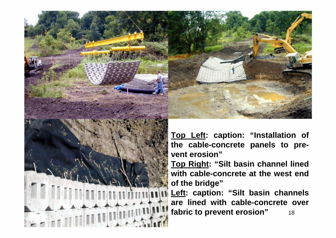
Top Left: caption: “Installation ofthe cable-concrete panels to pre-vent erosion”Top Right: “Silt basin channel linedwith cable-concrete at the west endof the bridge”Left: caption: “Silt basin channelsare lined with cable-concrete overfabric to prevent erosion”
19
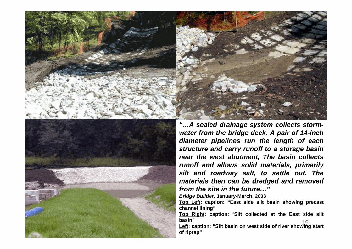
“…A sealed drainage system collects storm-water from the bridge deck. A pair of 14-inchdiameter pipelines run the length of eachstructure and carry runoff to a storage basinnear the west abutment, The basin collectsrunoff and allows solid materials, primarilysilt and roadway salt, to settle out. Thematerials then can be dredged and removedfrom the site in the future…”Bridge Builder, January-March, 2003Top Left: caption: “East side silt basin showing precastchannel lining”Top Right: caption: “Silt collected at the East side siltbasin”Left: caption: “Silt basin on west side of river showing startof riprap”
20
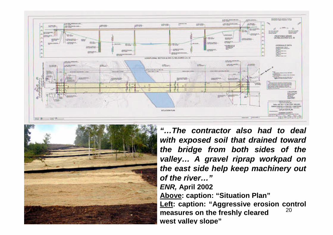
“…The contractor also had to dealwith exposed soil that drained towardthe bridge from both sides of thevalley… A gravel riprap workpad onthe east side help keep machinery outof the river…”ENR, April 2002Above: caption: “Situation Plan”Left: caption: “Aggressive erosion controlmeasures on the freshly clearedwest valley slope”
21
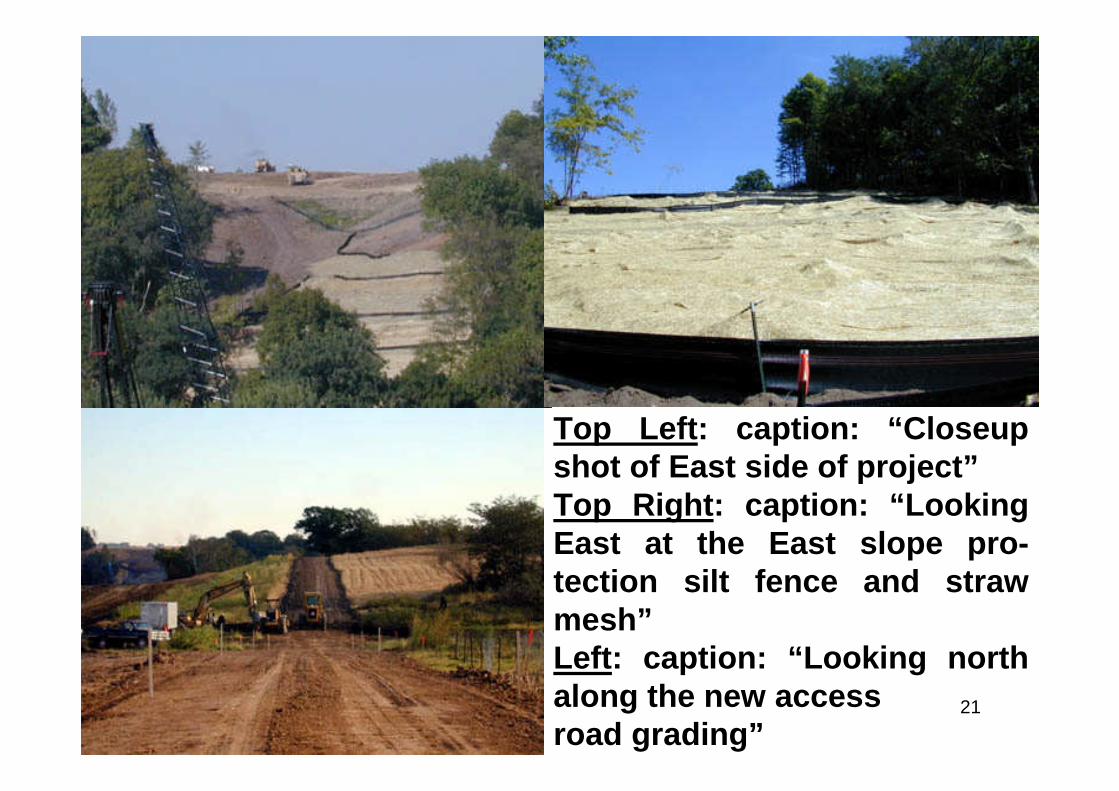
Top Left: caption: “Closeupshot of East side of project”Top Right: caption: “LookingEast at the East slope pro-tection silt fence and strawmesh”Left: caption: “Looking northalong the new accessroad grading”
22
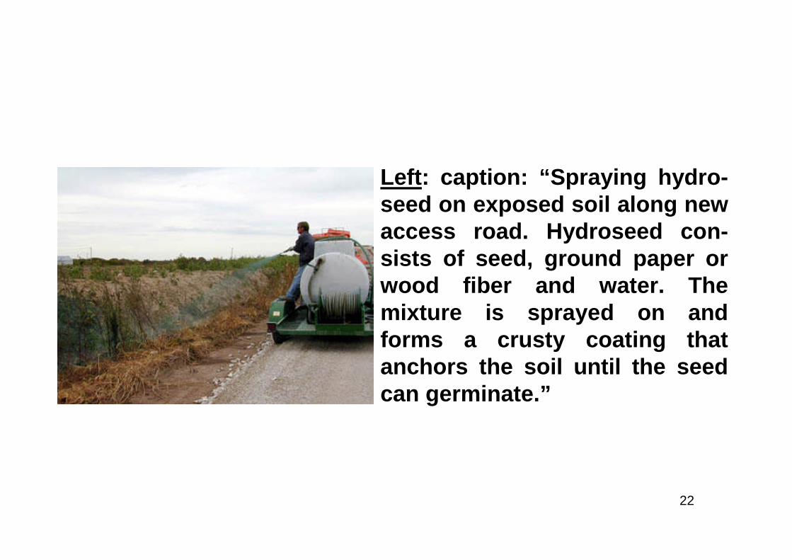
Left: caption: “Spraying hydro-seed on exposed soil along newaccess road. Hydroseed con-sists of seed, ground paper orwood fiber and water. Themixture is sprayed on andforms a crusty coating thatanchors the soil until the seedcan germinate.”
23
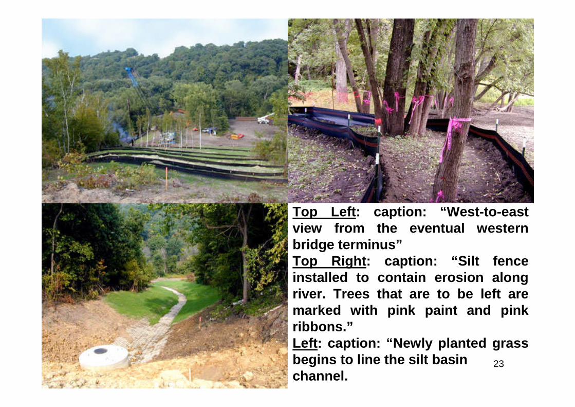
Top Left: caption: “West-to-eastview from the eventual westernbridge terminus”Top Right: caption: “Silt fenceinstalled to contain erosion alongriver. Trees that are to be left aremarked with pink paint and pinkribbons.”Left: caption: “Newly planted grassbegins to line the silt basinchannel.
24
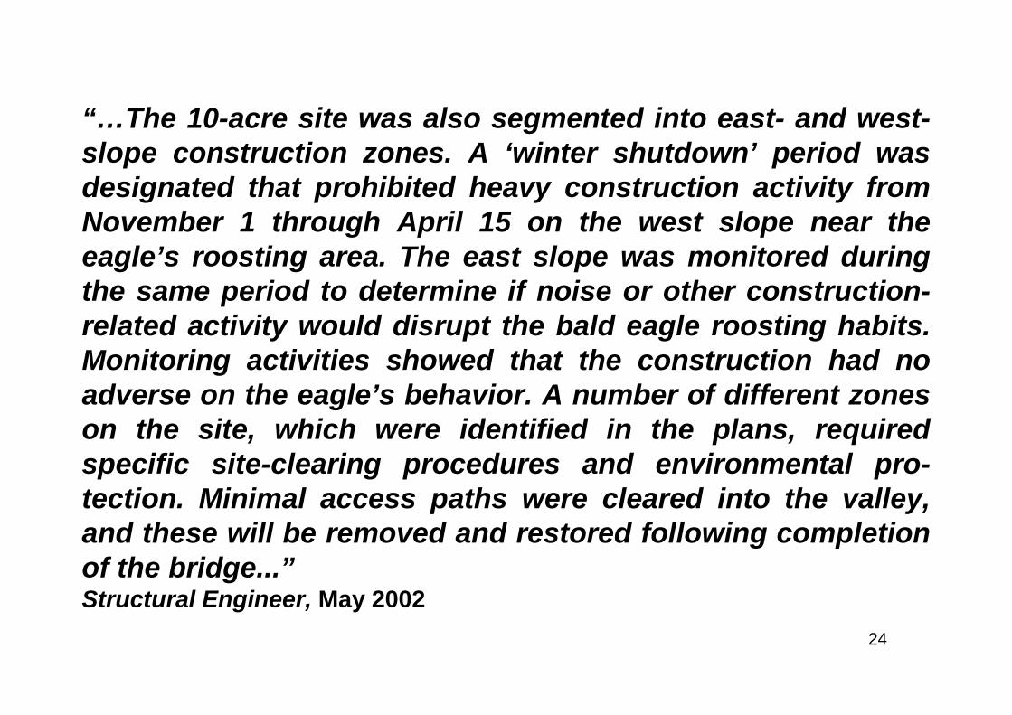
“…The 10-acre site was also segmented into east- and west-slope construction zones. A ‘winter shutdown’ period wasdesignated that prohibited heavy construction activity fromNovember 1 through April 15 on the west slope near theeagle’s roosting area. The east slope was monitored duringthe same period to determine if noise or other construction-related activity would disrupt the bald eagle roosting habits.Monitoring activities showed that the construction had noadverse on the eagle’s behavior. A number of different zoneson the site, which were identified in the plans, requiredspecific site-clearing procedures and environmental pro-tection. Minimal access paths were cleared into the valley,and these will be removed and restored following completionof the bridge...”Structural Engineer, May 2002
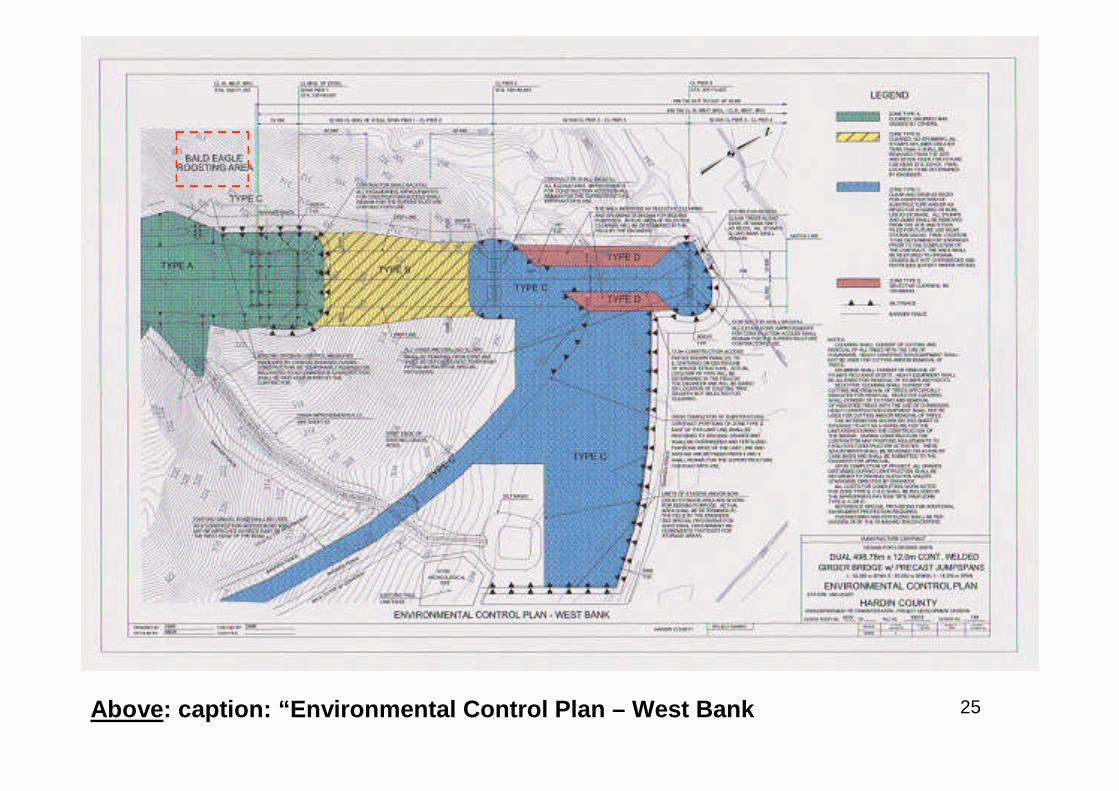
25Above: caption: “Environmental Control Plan – West Bank
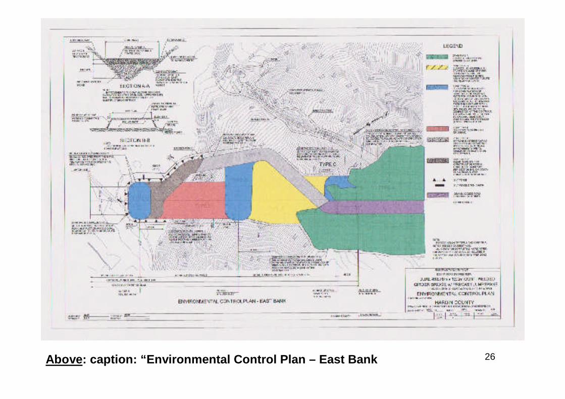
26Above: caption: “Environmental Control Plan – East Bank

27
Incremental Launch
28
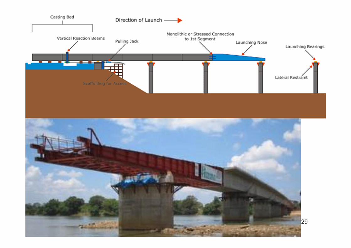
“…Because equipment access was limited and environmentalrestrictions were strictly enforced, HNTB engineers pushedforward with the launched erection sequence as the methodof construction. While it had never been employed for a long-span I-girder bridge made up of 10 million pounds ofstructural steel, the incremental launching technique hadbeen successfully used to erect more torsionally stableconcrete box structures in Europe, as well as a smaller steelbox girder railroad bridge in the United States. ContractorJensen Construction, Des Moines, Iowa, and erectionengineer Ashton Engineering, Davenport, Iowa, were up tothe challenge. Jensen modified some of the erection seq-uence’s roller and guidance systems to better suit itsschedule, available equipment, and materials. The cus-tomized equipment pushed approximately 5 million poundsof steel per bridge…”Bridge Builder, January-March, 2003
29
30
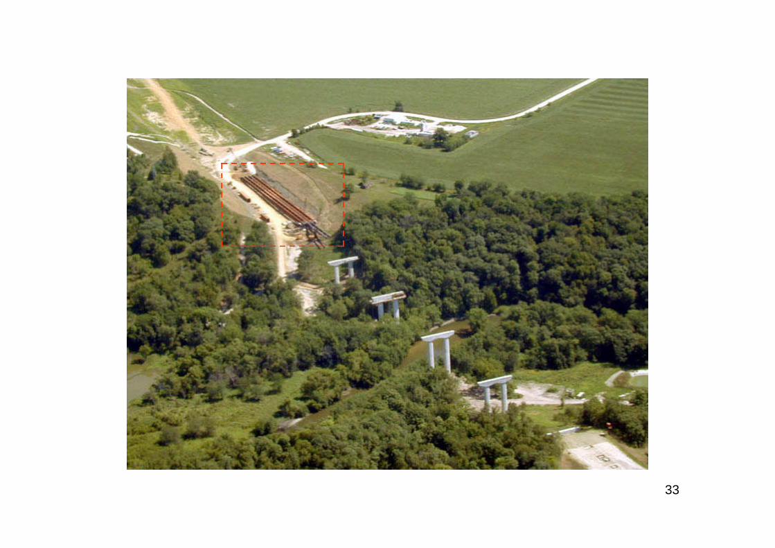
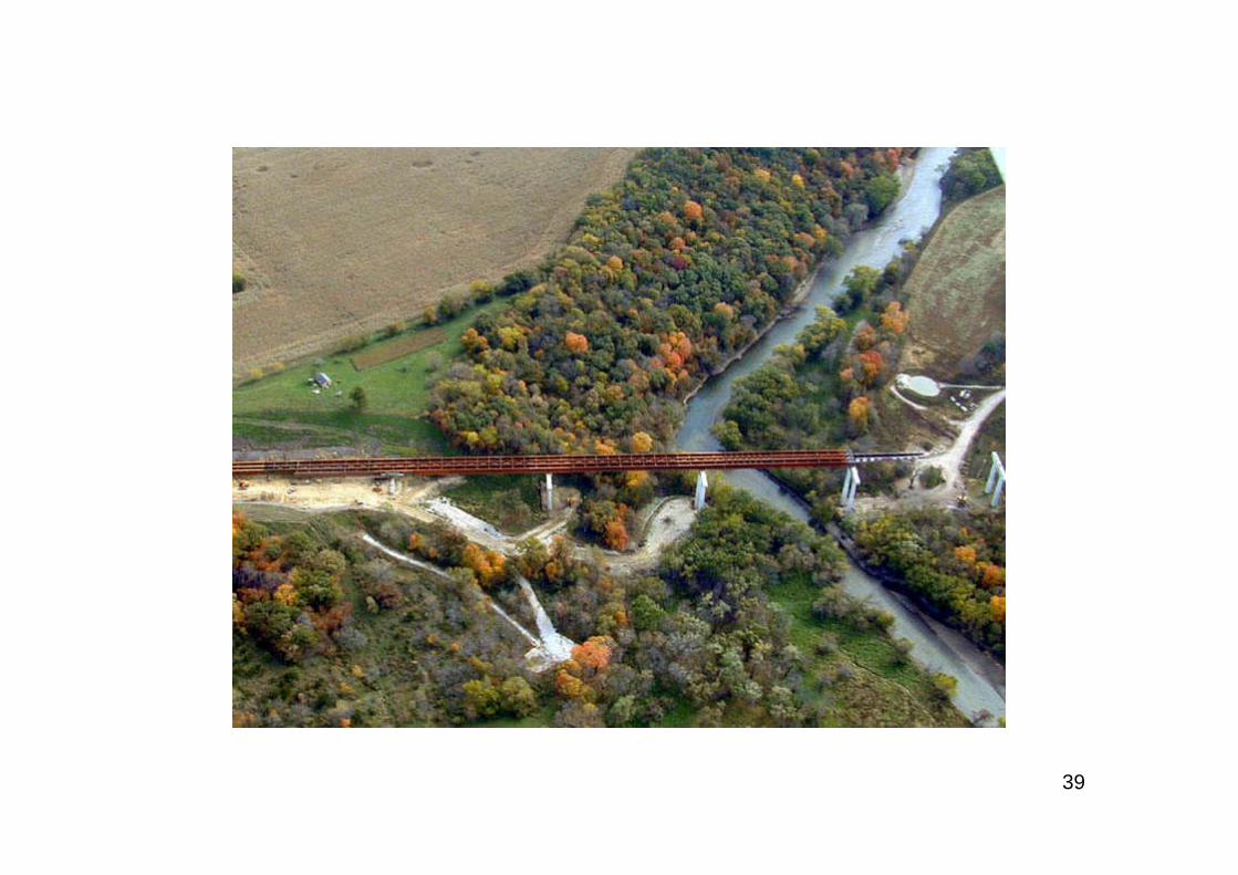
“…Construction of the substructure elements began inAugust 2000, and preparation of a 15-foot-deep, 600-foot-longlaunching pit behind the east abutment was completed inNovember 2000. The launching pit, dug beneath what wouldlater become the approach roadway, was used to construct anumber of temporary pile bents where sections of the I-girdersuperstructure would be assembled on rollers and laterpushed incrementally across the piers. Steel assembly for theeastbound bridge began in June 2001. After Jensencompleted the steel erection on each span in the launchingpit, including all diaphragms and lateral bracing, the steelwas launched downhill along a 0.64 percent grade, beingpushed by hydraulic pistons toward the west abutment at apace of about 1 fpm…”Bridge Builder, January-March, 2003
31
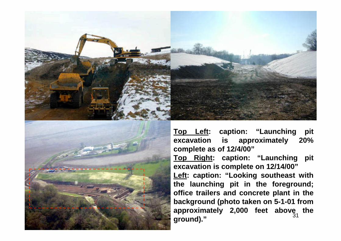
Top Left: caption: “Launching pitexcavation is approximately 20%complete as of 12/4/00”Top Right: caption: “Launching pitexcavation is complete on 12/14/00”Left: caption: “Looking southeast withthe launching pit in the foreground;office trailers and concrete plant in thebackground (photo taken on 5-1-01 fromapproximately 2,000 feet above theground).”
32
Top Left: caption: “Verticaland horizontal launchingrollers”Top Right: caption: “Overviewof steel assembly showingfirst six sections of girders”Left: caption: “Aerial view oflaunching pit prior to firstlaunch of bridge sections”
33
34
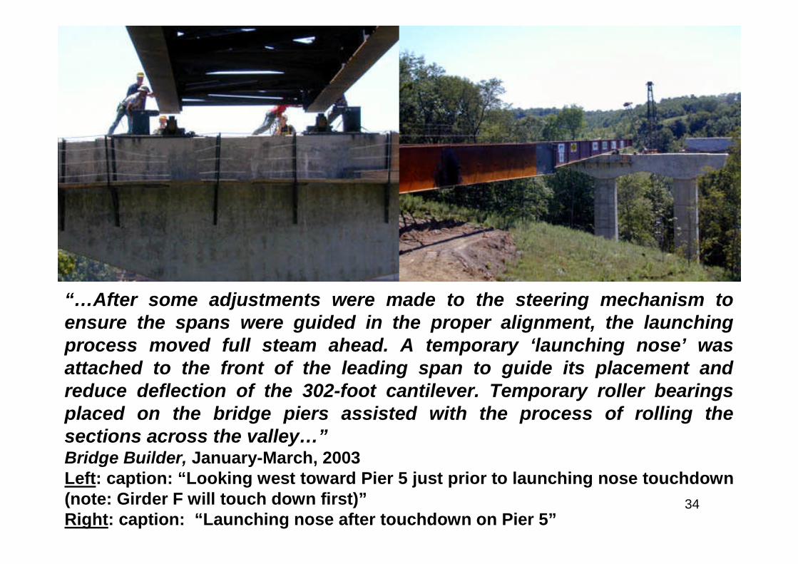
“…After some adjustments were made to the steering mechanism toensure the spans were guided in the proper alignment, the launchingprocess moved full steam ahead. A temporary ‘launching nose’ wasattached to the front of the leading span to guide its placement andreduce deflection of the 302-foot cantilever. Temporary roller bearingsplaced on the bridge piers assisted with the process of rolling thesections across the valley…”Bridge Builder, January-March, 2003Left: caption: “Looking west toward Pier 5 just prior to launching nose touchdown(note: Girder F will touch down first)”Right: caption: “Launching nose after touchdown on Pier 5”
35

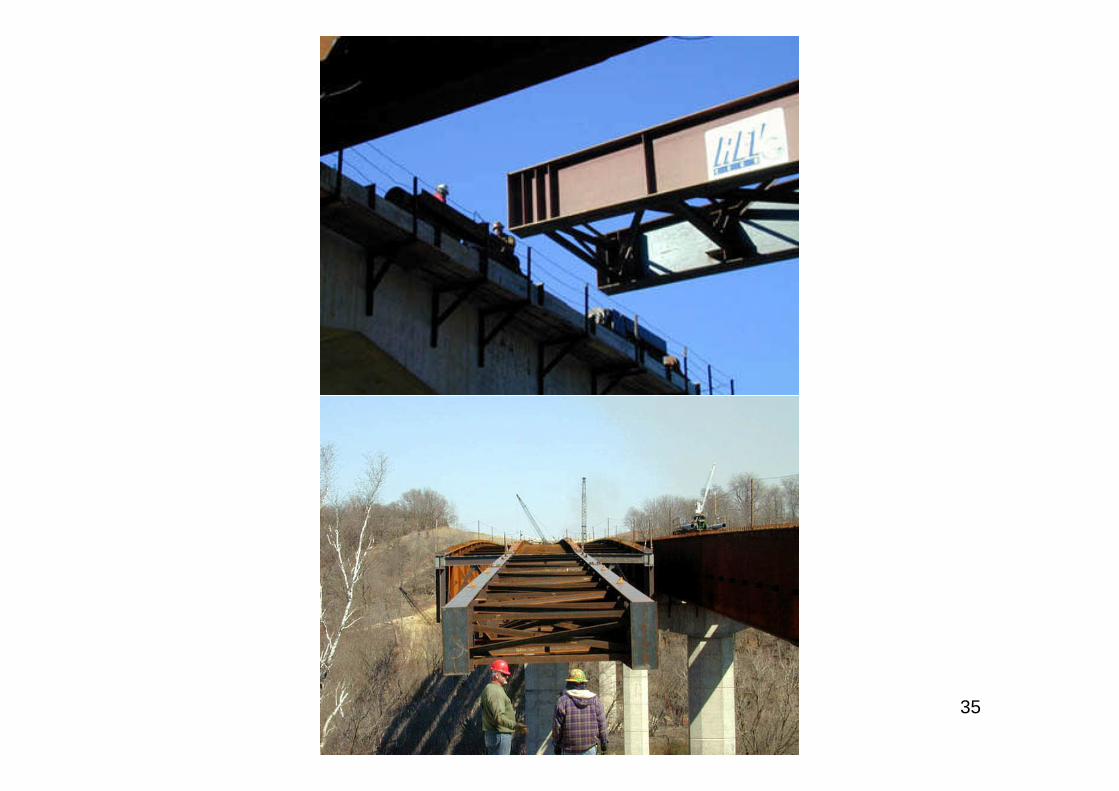
36Above: caption: “Tip of launching nose landing on roller used during thebridge launching”

37
38
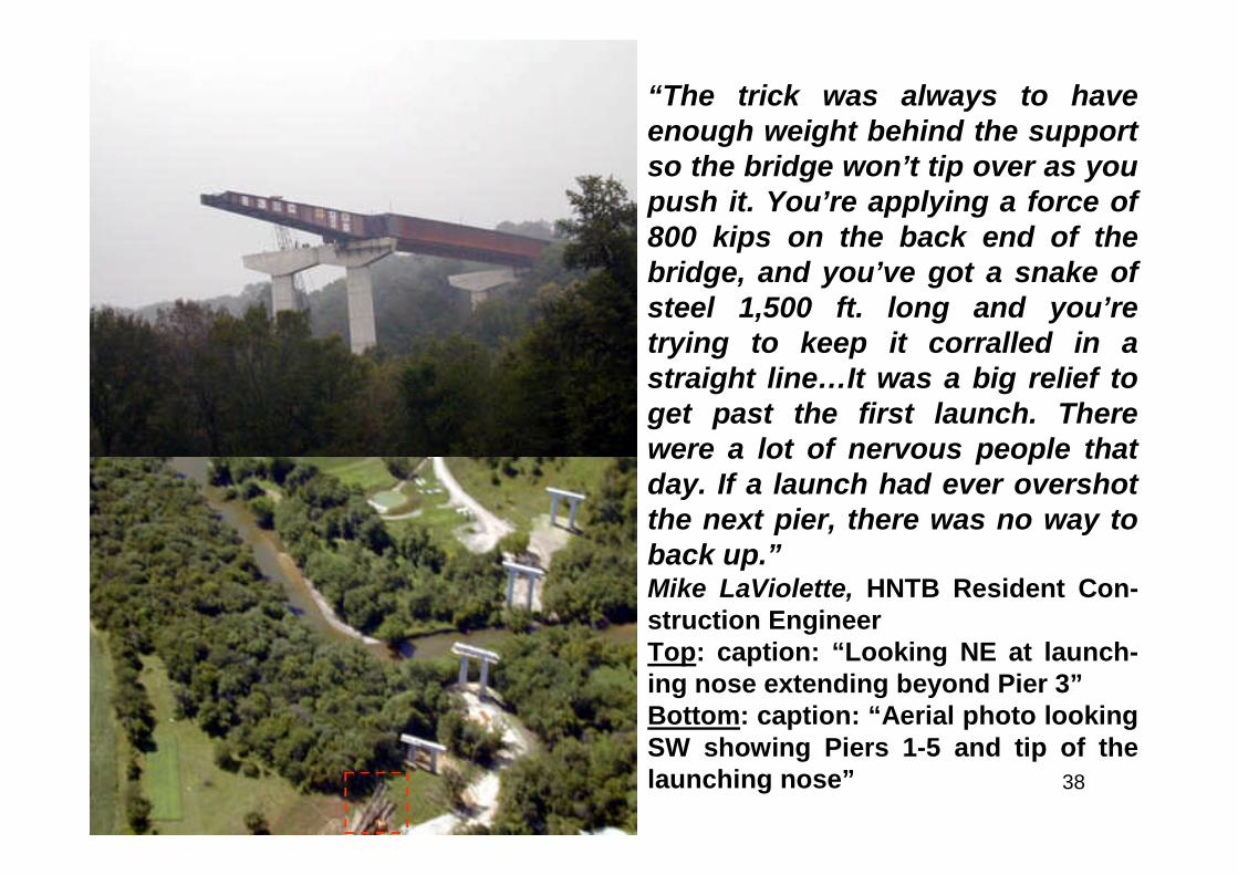
“The trick was always to haveenough weight behind the supportso the bridge won’t tip over as youpush it. You’re applying a force of800 kips on the back end of thebridge, and you’ve got a snake ofsteel 1,500 ft. long and you’retrying to keep it corralled in astraight line…It was a big relief toget past the first launch. Therewere a lot of nervous people thatday. If a launch had ever overshotthe next pier, there was no way toback up.”Mike LaViolette, HNTB Resident Con-struction EngineerTop: caption: “Looking NE at launch-ing nose extending beyond Pier 3”Bottom: caption: “Aerial photo lookingSW showing Piers 1-5 and tip of thelaunching nose”
39
40
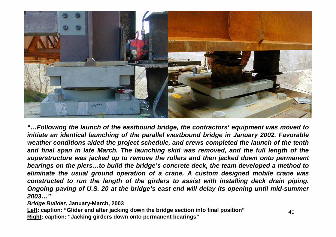
“…Following the launch of the eastbound bridge, the contractors’ equipment was moved toinitiate an identical launching of the parallel westbound bridge in January 2002. Favorableweather conditions aided the project schedule, and crews completed the launch of the tenthand final span in late March. The launching skid was removed, and the full length of thesuperstructure was jacked up to remove the rollers and then jacked down onto permanentbearings on the piers…to build the bridge’s concrete deck, the team developed a method toeliminate the usual ground operation of a crane. A custom designed mobile crane wasconstructed to run the length of the girders to assist with installing deck drain piping.Ongoing paving of U.S. 20 at the bridge’s east end will delay its opening until mid-summer2003…”Bridge Builder, January-March, 2003Left: caption: “Glider end after jacking down the bridge section into final position”Right: caption: “Jacking girders down onto permanent bearings”
41
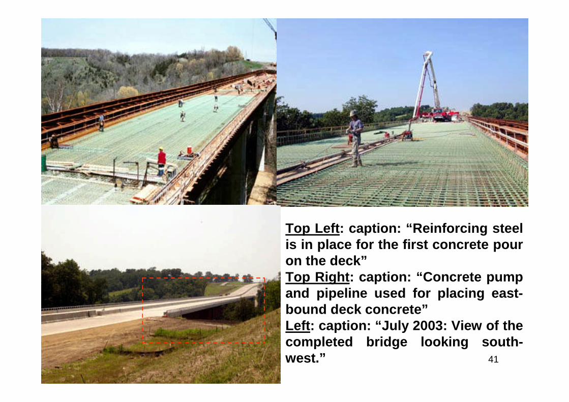
Top Left: caption: “Reinforcing steelis in place for the first concrete pouron the deck”Top Right: caption: “Concrete pumpand pipeline used for placing east-bound deck concrete”Left: caption: “July 2003: View of thecompleted bridge looking south-west.”
42
43
The Accomplishment

44
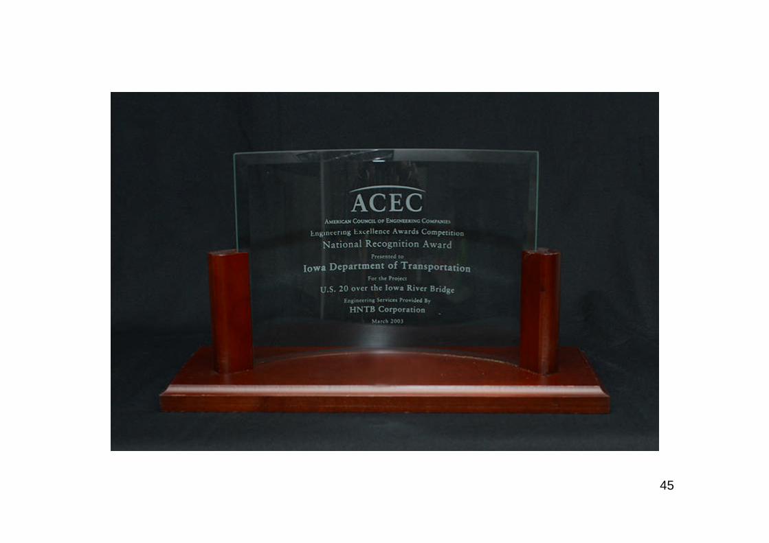
“…already the bridge is capturing attention. The project hasreceived a Grand Conceptor Award from the AmericanCouncil of Engineering Companies of Iowa and a GrandAward from the Consulting Engineers Council of Missouri. Italso was recognized by FHWA for engineering excellence inpursuit of environmental sensitivity. In addition, the project isa finalist in the Construction Innovation Foundation’s NOVAawards program, which recognizes significant advances inthe construction industry…other projects in other places willbenefit from the U.S. 20 bridge’s erection advances. Recently,a steel I-girder bridge in West Virginia was launched, whileanother bridge in Ohio is under design and scheduled tolaunch in 2005.”Bridge Builder, January-March, 2003
45
46
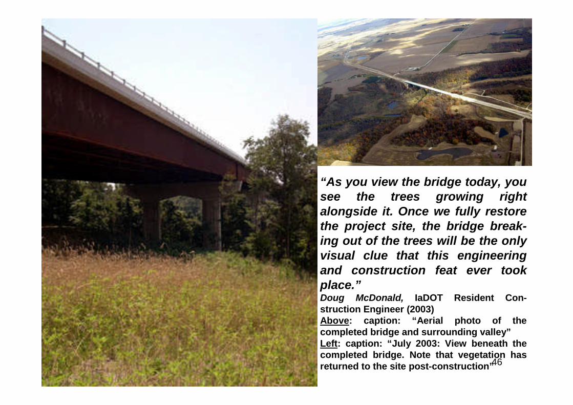
“As you view the bridge today, yousee the trees growing rightalongside it. Once we fully restorethe project site, the bridge break-ing out of the trees will be the onlyvisual clue that this engineeringand construction feat ever tookplace.”Doug McDonald, IaDOT Resident Con-struction Engineer (2003)Above: caption: “Aerial photo of thecompleted bridge and surrounding valley”Left: caption: “July 2003: View beneath thecompleted bridge. Note that vegetation hasreturned to the site post-construction”
47
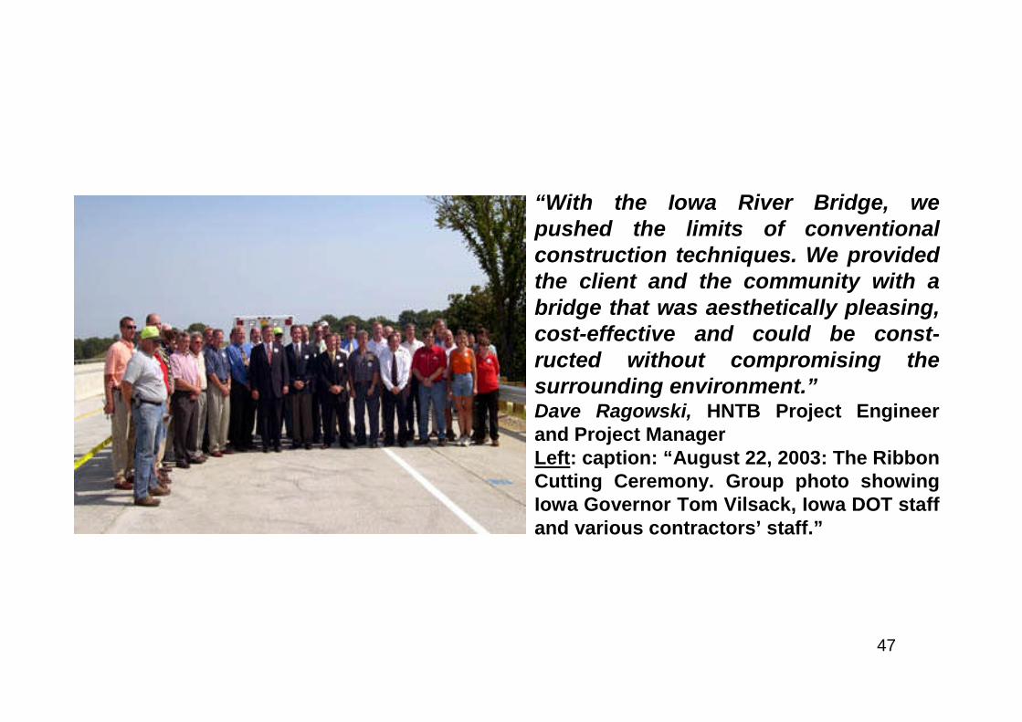
“With the Iowa River Bridge, wepushed the limits of conventionalconstruction techniques. We providedthe client and the community with abridge that was aesthetically pleasing,cost-effective and could be const-ructed without compromising thesurrounding environment.”Dave Ragowski, HNTB Project Engineerand Project ManagerLeft: caption: “August 22, 2003: The RibbonCutting Ceremony. Group photo showingIowa Governor Tom Vilsack, Iowa DOT staffand various contractors’ staff.”

48
“One doesn’t always want to be the first person to trysomething, but in this case we had little choice…The onlyway we could be successful on this project was to form a truepartnership among all parties involved. The results exceededmy expectations…The bridge is the golden spike in a corridorproject that has been under way since 1969”Bob Younie, Construction Engineer - IaDOT District 1
49
“…I want to congratulate the Iowa Department of Trans-portation and its many partners for developing and buildingthe Iowa River Bridge. This project not only addressesimportant transportation needs but it preserves and protectsthe surrounding environment as well. It offers all of us anexample of how transportation and environmental pro-fessionals can collaborate to provide a transportation facilityto improve safety, mobility, and opportunities for economicdevelopment in an environmentally sensitive manner.”Mary E. Peters, Federal Highway Administrator (September 16th 2002)RE: the IaDOT’s’ receipt of the Federal Highway Administrator's EnvironmentalQuality Award for its work on the Iowa River Bridge.
50