toward a general purpose computer ii example: game of life
Post on 21-Dec-2015
222 views
TRANSCRIPT

Toward a general purpose computer II
Example: Game of Life

Problems in the previous implementation
1. Similar instructions in different parts of the algorithm require different lines
Very large ROM
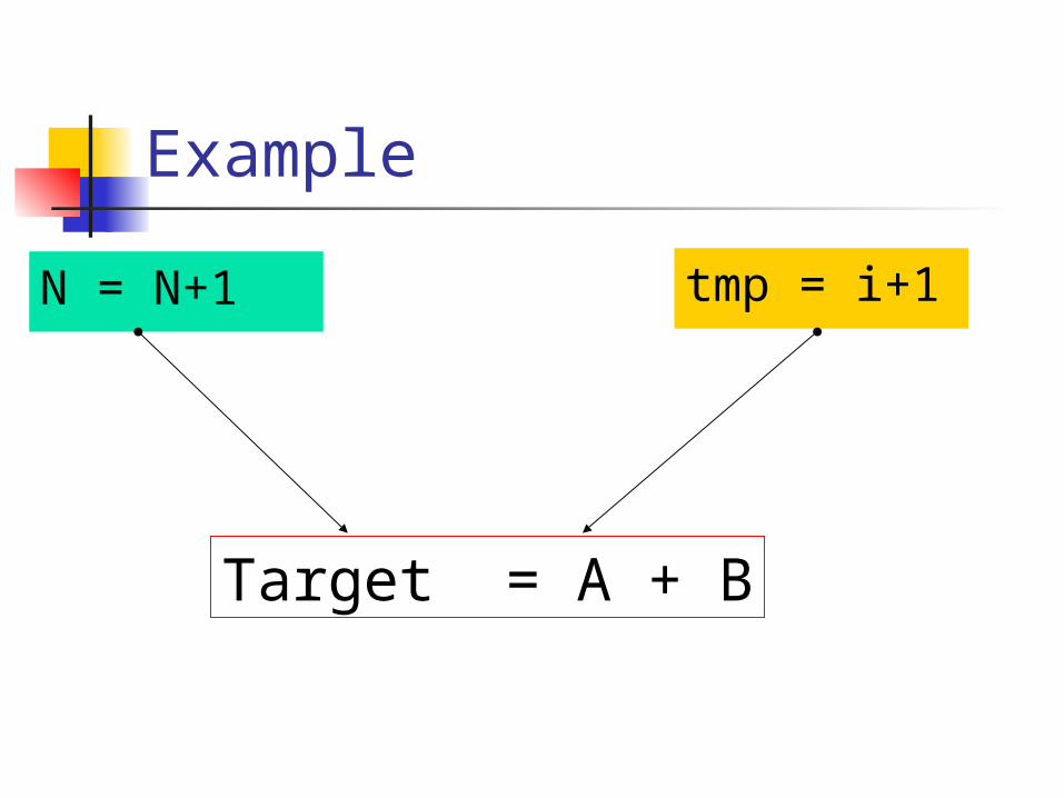
Example
N = N+1 tmp = i+1
Target = A + B

Problems in the previous implementation
2. All the variables of the algorithm are stored in registers.
1. Change in the algorithm will require change in hardware2. Registers are expansive.3. There is limited space.
Solution to 1 (and 2)
Define more general instructions
The algorithm will be a set of the general instructions.
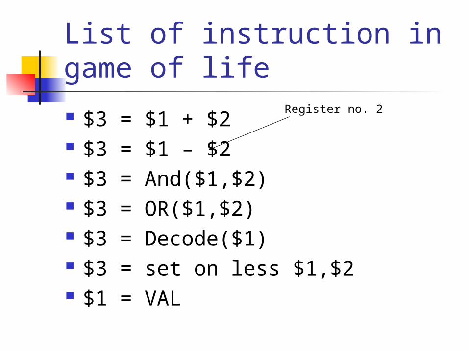
List of instruction in game of life
$3 = $1 + $2 $3 = $1 – $2 $3 = And($1,$2) $3 = OR($1,$2) $3 = Decode($1) $3 = set on less $1,$2 $1 = VAL
Register no. 2

The set on less instruction
$3 = set on less $1,$2 $3 = 00000…01 if $1 < $2 $3 = 00000…00 otherwise.
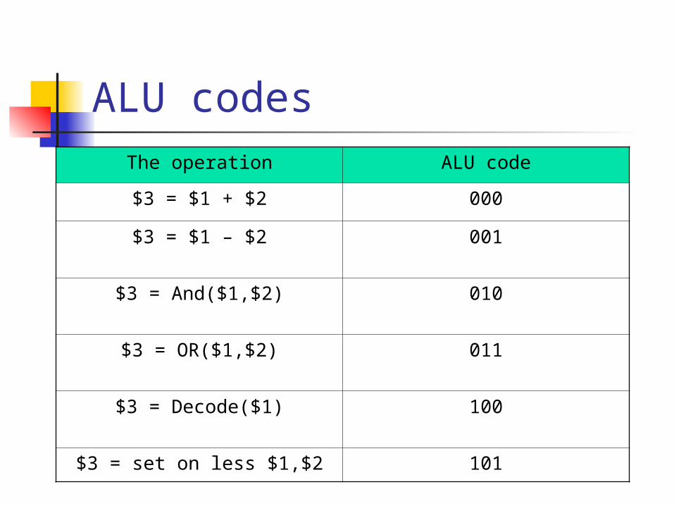
ALU codesThe operation ALU code
$3 = $1 + $2 000
$3 = $1 – $2 001
$3 = And($1,$2) 010
$3 = OR($1,$2) 011
$3 = Decode($1) 100
$3 = set on less $1,$2 101
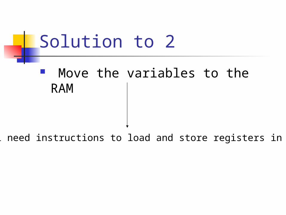
Solution to 2
Move the variables to the RAM
We will need instructions to load and store registers in the RAM
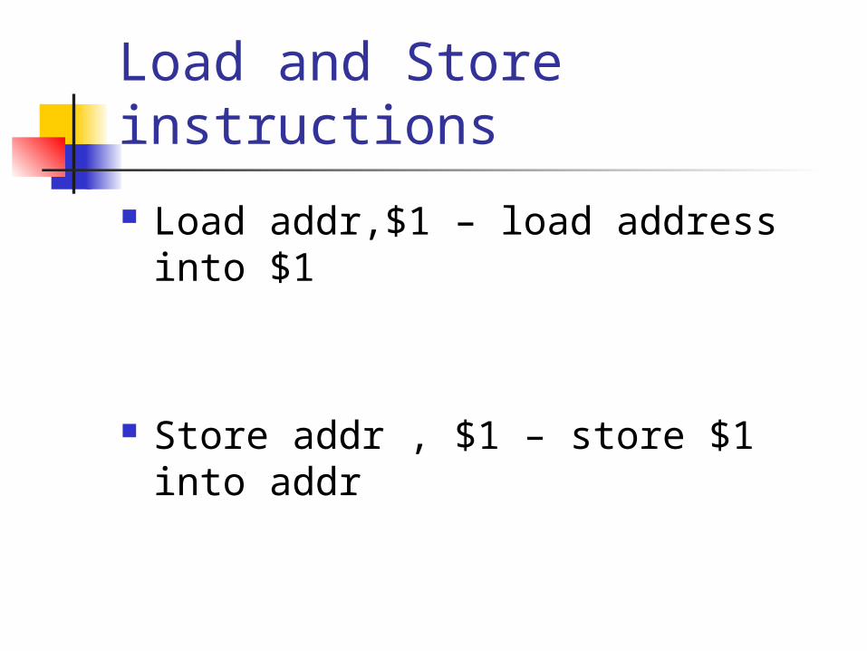
Load and Store instructions
Load addr,$1 – load address into $1
Store addr , $1 – store $1 into addr
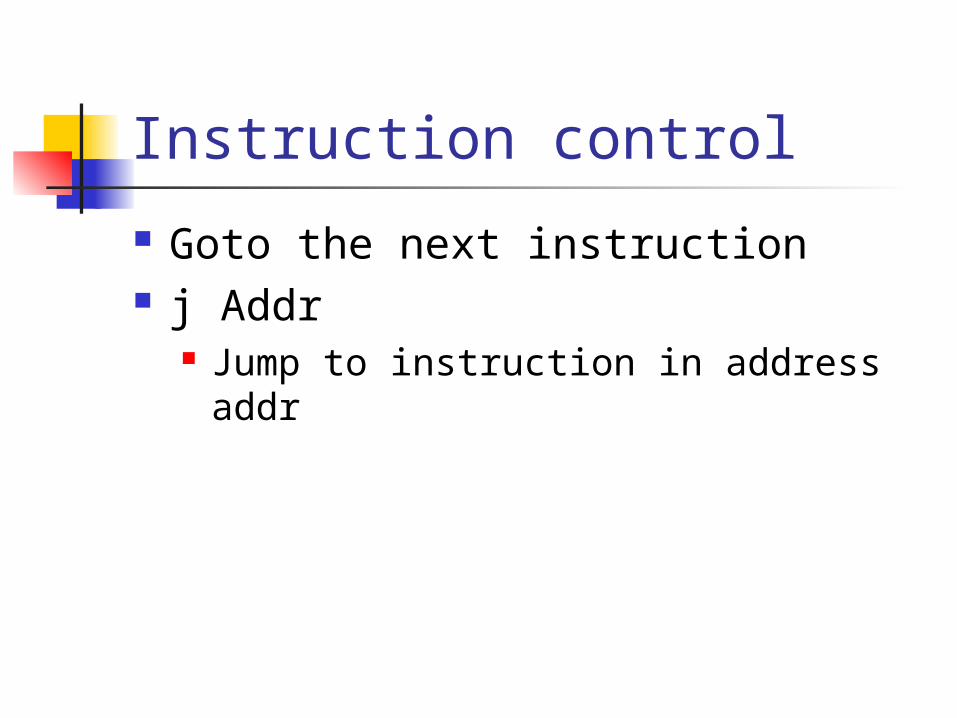
Instruction control
Goto the next instruction j Addr
Jump to instruction in address addr
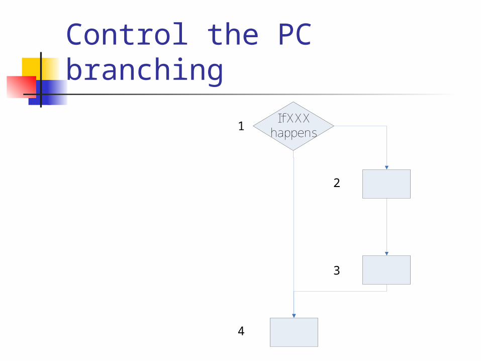
Control the PC branchingIf XXX
happens1
2
3
4

Control the PC branchingIf XXX
happens1
2
3
4
1. PC = PC+12. Check xxx happened
If it didn’t PC = 43. IR PC
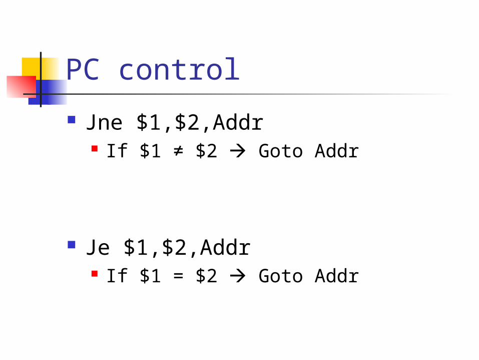
PC control
Jne $1,$2,Addr If $1 ≠ $2 Goto Addr
Je $1,$2,Addr If $1 = $2 Goto Addr
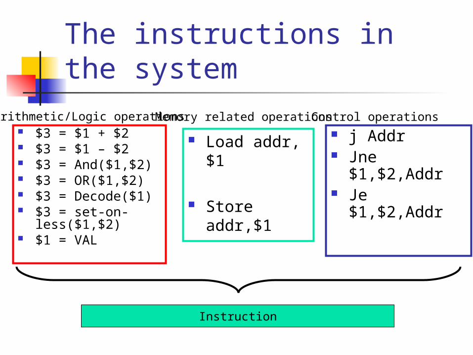
The instructions in the system
$3 = $1 + $2 $3 = $1 – $2 $3 = And($1,$2) $3 = OR($1,$2) $3 = Decode($1) $3 = set-on-
less($1,$2) $1 = VAL
Arithmetic/Logic operations
Load addr,$1
Store addr,$1
Memory related operations j Addr Jne $1,$2,Addr Je $1,$2,Addr
Control operations
Instruction

Assumptions: We have 16 registers $1…$26
($0 is always zero).
The RAM has 65536 entries of 16bits (16bit address)
The program ROM has 65536 entriesof 32bits each.
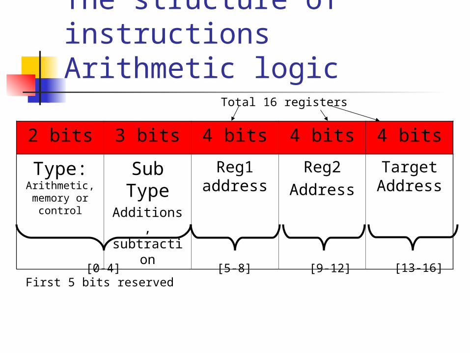
The structure of instructionsArithmetic logic
2 bits 3 bits 4 bits 4 bits 4 bits
Type: Arithmetic, memory or
control
Sub Type
Additions,subtraction
Reg1 address
Reg2Address
Target Address
[0-4]First 5 bits reserved
Total 16 registers
[5-8] [9-12] [13-16]
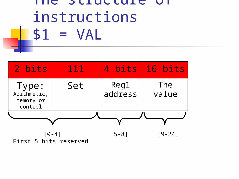
The structure of instructions$1 = VAL
2 bits 111 4 bits 16 bits
Type: Arithmetic, memory or
control
Set Reg1 address
The value
[0-4]First 5 bits reserved
[5-8] [9-24]
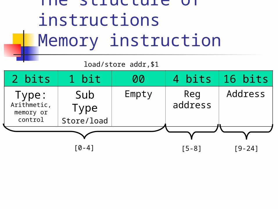
The structure of instructionsMemory instruction
2 bits 1 bit 00 4 bits 16 bits
Type: Arithmetic, memory or
control
Sub Type
Store/load
Empty Reg address
Address
load/store addr,$1
[0-4] [5-8] [9-24]
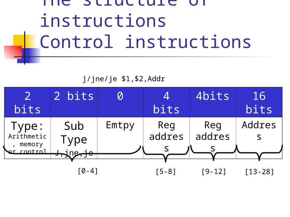
The structure of instructionsControl instructions
2 bits 2 bits 0 4 bits 4bits 16 bits
Type: Arithmetic, memory or
control
Sub TypeJ,jne,je
Emtpy Reg address
Reg address
Address
j/jne/je $1,$2,Addr
[0-4] [5-8] [9-12] [13-28]

Note about the control instructions
In the j instruction we ignore the first and second fields.
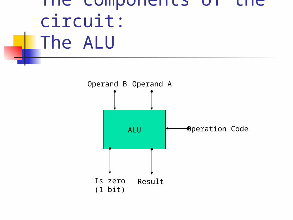
The components of the circuit:The ALU
ALU Operation Code
Operand AOperand B
ResultIs zero(1 bit)

The components of the circuit:The Registers
Registers
Data 1
Data 2
Data 1 Address
Data 2 Address
WriteAddress
Write Data
Write
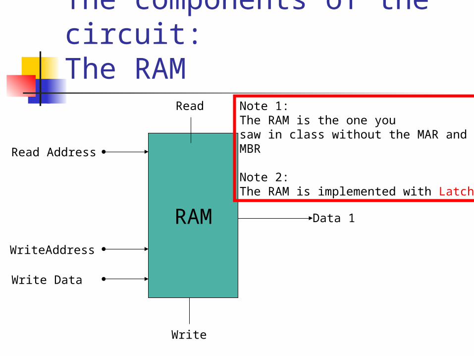
The components of the circuit:The RAM
RAM Data 1
Read Address
WriteAddress
Write Data
Write
Read Note 1: The RAM is the one you saw in class without the MAR and MBR
Note 2: The RAM is implemented with Latches!
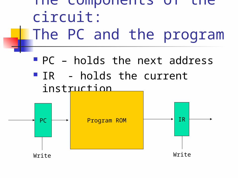
The components of the circuit:The PC and the program
PC – holds the next address IR - holds the current instruction
PC Program ROM
Write
IR
Write
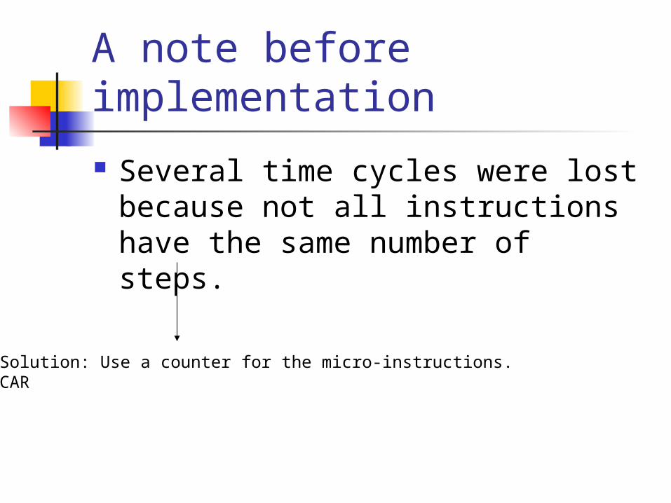
A note before implementation
Several time cycles were lost because not all instructions have the same number of steps.
Solution: Use a counter for the micro-instructions.CAR

The components of the circuit:CAR, example with arithmetic instruction
CAR = 0: IRPC, PC=PC+1, CAR=CAR++
CAR = 1: Perform the codeCAR = 0
Goto the next instruction

The components of the circuit:CAR, example with jne $1,$2,Addr
CAR = 0: IRPC, PC=PC+1, CAR=CAR++
CAR = 1: $1-$2, if not zero PCAddr
CAR = 0
Goto the next instruction

The components of the circuit:CAR, example with arithmetic instruction
CAR = 0: IRPC, PC=PC+1, CAR=CAR++
CAR = 1: Perform the code
Goto the next instruction
For efficiency, we will NOT use the ALU here.
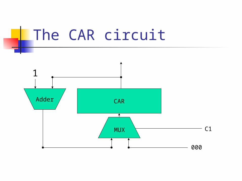
The CAR circuit
CARAdder
1
MUX C1
000
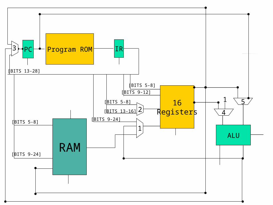
ALU
16Registers
RAM
PC Program ROM IR
1
4
51
[BITS 13-28]
[BITS 5-8]
[BITS 9-12]
[BITS 9-24]
2[BITS 13-16]
[BITS 5-8]
[BITS 9-24]
[BITS 5-8]
3

ALU
16Registers
RAM
PC Program ROM IR
1
4
51
3
2
Mirco-instructions[BITS 0-4]
All the control in the system
CAR
0
21
0 1
0 1
0
1
[BITS 13-28]
[BITS 5-8]
[BITS 9-12]
[BITS 9-24]
[BITS 13-16]
[BITS 5-8]
[BITS 9-24]
[BITS 5-8]

ALU
16Registers
RAM
PC Program ROM IR
1
4
51
3
2
Write
Read
Write
ALUop
IRloadPCload
Mux3
Mux2
Mux1
Mux4
Mux5
CAR
CAR control

The micro-instruction ROM
Inst. CAR ALUop
PCload
IRload
RAM
read
RAMwrit
e
RegWrite
CAR control
Mux
1 2 3 4 5
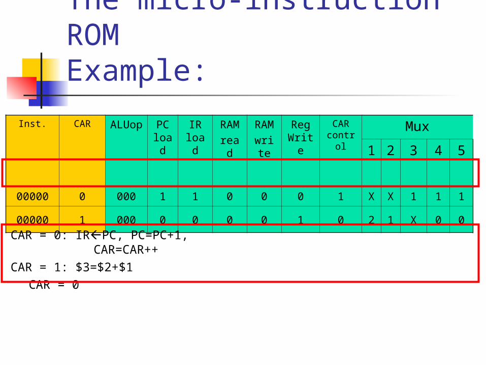
The micro-instruction ROMExample:
Inst. CAR ALUop
PCload
IRload
RAMread
RAMwrit
e
RegWrit
e
CAR contro
l
Mux
1 2 3 4 5
00000 0 000 1 1 0 0 0 1 X X 1 1 1
00000 1 000 0 0 0 0 1 0 2 1 X 0 0
CAR = 0: IRPC, PC=PC+1, CAR=CAR++
CAR = 1: $3=$2+$1CAR = 0

The micro-instruction ROMExample:
Inst. CARALUo
p
PCload
IRload
RAMread
RAMwrit
e
RegWrit
e
CAR contro
l
Mux
1 2 3 4 5
00000 0 000 1 1 0 0 0 1 X X 2 1 1
00000 1 000 0 0 0 0 1 0 2 1 X 0 0
CAR = 0: IRPC, PC=PC+1, CAR=CAR++
CAR = 1: $3=$2+$1CAR = 0
The meaning is:Put in PC the resultOf PC+1
We don’t care about these

The micro-instruction ROMExample:
Inst. CARALUo
p
PCload
IRload
RAMread
RAMwrit
e
RegWrit
e
CAR contro
l
Mux
1 2 3 4 5
00000 0 000 1 1 0 0 0 1 X X 2 1 1
00000 1 000 0 0 0 0 1 0 2 1 X 0 0
CAR = 0: IRPC, PC=PC+1, CAR=CAR++
CAR = 1: $3=$2+$1CAR = 0

In addition
In order to implement the jne instruction we need a conditional write on the PC.
The essence is in here
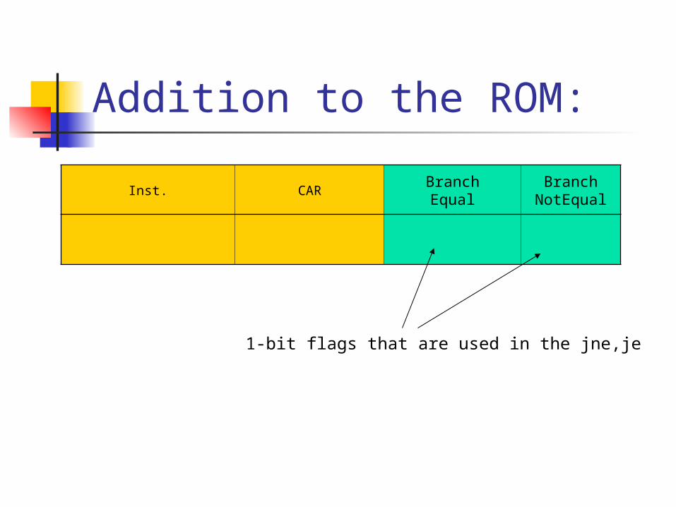
Addition to the ROM:
Inst. CARBranchEqual
BranchNotEqual
1-bit flags that are used in the jne,je

ALU
PC Program ROM IRMirco-instructions
Zero status bit
Branch equal
Branch not equal
PC write

The program ROM
Address Instruction Meaning
0000 00000000100100011
$3=$2+$1
0001 ……
Instruction type 00
Instruction sub type
Reg1
Reg2
Reg3

Saving more space
The fetch is divided into 2 cycles Fetch instruction Goto Right instruction
The ROM will depend on the CAR alone
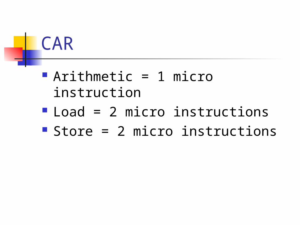
CAR
Arithmetic = 1 micro instruction Load = 2 micro instructions Store = 2 micro instructions

CAR – the instruction-CAR table
Instruction CAR
Arithmetic Operation
00010
Load 00011
00100
Store 00101
00110
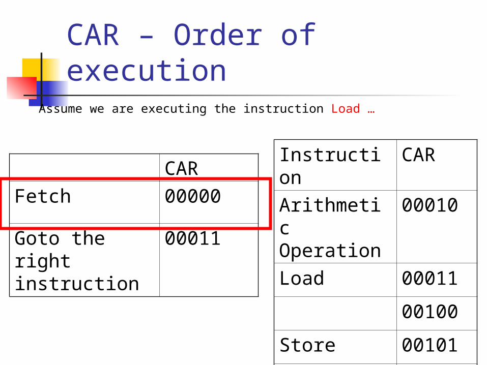
CAR – Order of execution
CAR
Fetch 00000
Goto the right instruction
00011
Instruction CAR
Arithmetic Operation
00010
Load 00011
00100
Store 00101
00110
Assume we are executing the instruction Load …

CAR – Order of execution
CAR
Fetch 00000
Goto the right instruction
00011
Instruction CAR
Arithmetic Operation
00010
Load 00011
00100
Store 00101
00110
Assume we are executing the instruction Load …
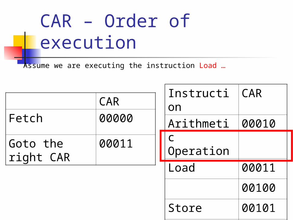
CAR – Order of execution
CAR
Fetch 00000
Goto the right CAR
00011
Instruction CAR
Arithmetic Operation
00010
Load 00011
00100
Store 00101
00110
Assume we are executing the instruction Load …
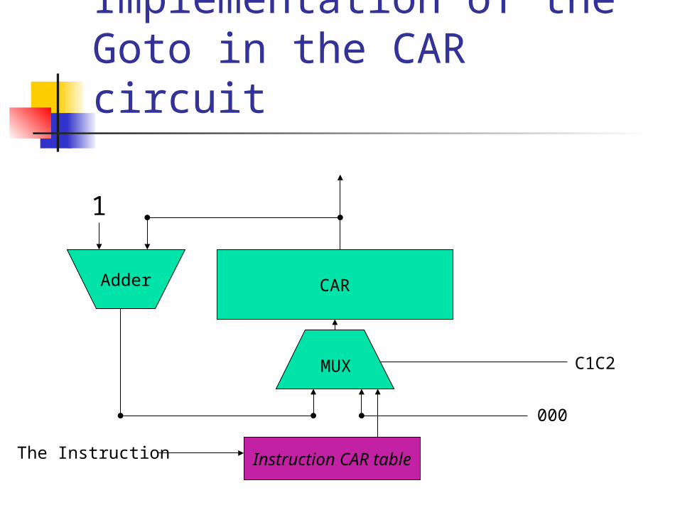
Implementation of the Goto in the CAR circuit
CARAdder
1
MUX C1C2
000
Instruction CAR tableThe Instruction

ALU
16Registers
RAM
PC Program ROM IR
1
4
51
3
2
Mirco-instructions
[BITS 0-4]
All the control in the system
CAR
0
21
0 1
0 1
0
1
[BITS 13-28]
[BITS 5-8]
[BITS 9-12]
[BITS 9-24]
[BITS 13-16]
[BITS 5-8]
[BITS 9-24]
[BITS 5-8]

The micro-instruction ROM
CAR ALUop
PCload
IRload
RAM
read
RAMwrit
e
RegWrite
CAR control
Mux
1 2 3 4 5
The micro instruction ROM depends on the CAR only now.