towards optimum design of magnetic adhesion wall …
TRANSCRIPT
Salman Hussain Page 1 of 12
26th International Conference of CAD/CAM, Robotics & Factories of the Future
26-28 July 2011, Kuala Lumpur, Malaysia
TOWARDS OPTIMUM DESIGN OF MAGNETIC ADHESION WALL CLIMBING
WHEELED ROBOTS
Salman, H., Sattar, T.P., Salinas, E.
London South Bank University, Faculty of Engineering, Science & the Built
Environment, London, UK
e-mail: [email protected]
ABSTRACT
Climbing and walking robots perform tasks that are too difficult, dangerous or time
consuming for the human worker. The main design consideration in the climbing robot is its
method of adhesion. The aim of this paper is to lay down the foundation for developing a
design framework for magnetically adhering wheeled robots having magnets attached to the
base of the robot. The different design parameters affecting the magnetic adhesion include
the geometry of the flux concentration plate, effect of the variation of the air gap on adhesion
and climbing performance, different materials for magnetic flux concentration and different
magnetic arrangements. These different parameters affecting adhesion are simulated and
optimized using Magnetostatic analysis in ANSYS simulation software.
Keywords: Wall climbing robot, magnetic adhesion optimization, robot design optimization
1 INTRODUCTION
Climbing and walking robots perform tasks that are too difficult, dangerous or time
consuming for the human worker [1, 2] . The main design consideration in the climbing
robot is its method of adhesion. Methods of adhesion include Magnetic, Pneumatic,
Gecko and Vortex [3]. This paper focuses on magnetic adhesion for Wall climbing
robots.
There are three different magnet deployment configurations to achieve adhesion in
wheeled wall climbing robots. . They achieve adhesion by using magnetic wheels [4-10],
magnetic tracks [11-13]and magnets attached to the base of the body [1].
A few researchers have tried to optimize adhesion based on magnetic wheel [4, 13]and
magnetic track adhesion [11], but these have been limited to specific robots. Also, this
work has focused on only one or two variables affecting the optimization. To our
knowledge, no work has been done to address the entire possible optimization variables
and especially the optimization of robot design with magnets attached to the body of the
robot. This paper addresses all the possible optimization variables for magnetic adhesion
when the magnets are attached to the body of the robot. The comparison of different
optimization parameters gives a useful insight into stability of the robot and will help in
deciding how to select different design parameters.
2 BACKGROUND
The aim of this paper is to lay down the foundation for developing a design framework
for magnetically adhering wheeled robots.
The design cycle comprises of a two step process. The steps are to optimize design and to
optimize adhesion. In design optimization, a static and dynamic force analysis is carried
out. This analysis serves to optimize design parameters by considering the adhesion force
requirement, dimensions of the robot, material properties to allow selection of materials,

Salman Hussain Page 2 of 12
26th International Conference of CAD/CAM, Robotics & Factories of the Future
26-28 July 2011, Kuala Lumpur, Malaysia
the robot configuration and its center of gravity. The parameters obtained from this step
provide a gateway to the second step of the design cycle, i.e. adhesion optimization.
The parameters for adhesion optimization depend on methods to strengthen the magnetic
field using flux concentrator, the geometry of the flux concentrator, material of the flux
concentrator, effect of the variation of the air gap on adhesion and climbing performance,
different magnetic arrangements and the effect of wall thickness variations. Their effects
are studied using simulations based on Finite Element methods using Magnetostatic
analysis in ANSYS. Some of the results are validated by experimentation.
3 DESIGN OPTIMIZATION
Static and dynamic force analysis is necessary to analyze and design the optimum design
parameters. In this section, Static and dynamic force analysis for the wall climbing robot
is carried out.
3.1 Static Analysis
The stability of the wall climbing robot depends mainly on turn-over failure, sliding
failure and roll-over failure as shown in Figure 1. Static analysis helps to find the design
parameters to address these stability concerns.
Figure 1: Stability factors a) turn-over failure; b) sliding failure, c) roll-over failure
3.1.1 Sliding avoidance
The ideal wall climbing robot should do climbing surface transitions and climb on
surfaces with different slopes. To understand the forces acting on a robot, consider the
forces acting on a robot resting on an inclined plane as shown in
Figure 2. The slope of the inclined plane is “θ”.
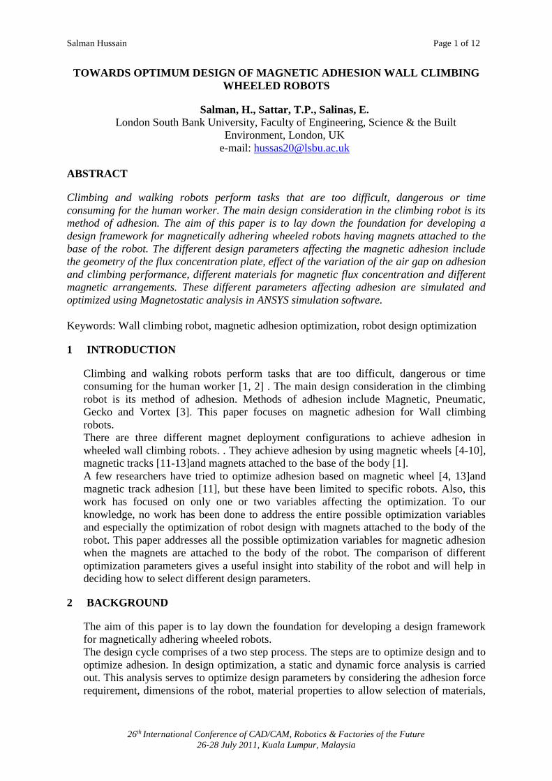
W= weight of the robot
= angle of inclination
mF = magnetic adhesion force
= coefficient of friction of wheels
d = distance of centre of gravity from the climbing surface
L = distance between front and rear wheels
Salman Hussain Page 3 of 12
26th International Conference of CAD/CAM, Robotics & Factories of the Future
26-28 July 2011, Kuala Lumpur, Malaysia
Figure 2: free body diagram of robot moving on an inclined plane
sin
sin
cos
0cos
WN
or
NWF
FWN
NFWF
x
m
my
For the robot to avoid slipping
cos
sinW
WFm
For the special case of wall climbing robot moving on a vertical surface
(1)
In order to avoid sliding/slipping of the robot, the magnetic adhesion force should be
greater than
W . The stability of the robot can be increased by either increasing the
coefficient of friction of wheel tyre or decreasing the robot weight.
3.1.2 Turn-over avoidance
From
cossin
sincos
WW
F
WFW
m
m
WFm
90
W
d
A
R/4
L
W
θ
Wsinθ
N
θ
Wsinθ
Wcosθ
μN

Salman Hussain Page 4 of 12
26th International Conference of CAD/CAM, Robotics & Factories of the Future
26-28 July 2011, Kuala Lumpur, Malaysia
Figure 2, Taking moment about point A,
L
dWF
RF
L
dWR
LR
dWM
m
m
2
2
02
To avoid Turn over, the adhesion force should satisfy equation 2.
L
dWFm
2
(2)
For a given adhesion force, equation 2 can be satisfied by minimising the ratioL
d. This
means that the centre of gravity should be as close to the surface as possible and the
distance between the wheels should be large. Equation (2) shows that in order to avoid
turnover, the robot centre of gravity should be kept as low as possible.
The stability criteria to avoid sliding and turn over:
L
dWWFm
2,max
(3)
3.1.3 Roll-over avoidance
For simplicity, we assume that the shear force on the robot always acts perpendicular to
the wheel. Consider Figure 3(a), the roll over moment rM will then be
0)(2)( 1 LFkWM sr
)(2)( 1LFkW s
1
)(2
L
kWFs
Figure 3: Roll-over forces when a robot is at different orientations on the wall
k=distance between centre of gravity and point A

Salman Hussain Page 5 of 12
26th International Conference of CAD/CAM, Robotics & Factories of the Future
26-28 July 2011, Kuala Lumpur, Malaysia
sF =shearing force on each wheel
L1 =moment arm, distance between wheel 4 and 1
If order to avoid roll over,
12
)(
L
kWFs
(4)
The roll-over force varies with the angle of the robot on the wall (Figure 3 (b) and (c)).
This is due to the variation of the moment arm with different orientations of the robot.
The robot length (distance between the wheels) and the location of its centre of gravity
are important design considerations. These parameters play an important role in
determining the motion and stability of the wall climbing robot.
3.2 Dynamic Analysis
The design for the motor torque requirement will be based on torque analysis when the
robot is moving upward. This is due to the fact that the torque required for a climbing
robot to move will be maximum when the robot is moving upward. Consider a robot on a
wall moving upward as shown in Figure 4.
Figure 4: Moment force diagram for robot moving upward
a = distance between centre of gravity of robot and wheel centre
M = total torque required for the robot to move upward
wM = torque required by each wheel
O = centre of the wheel
r = radius of the wheel
rF = rolling force required
The moment about point O is
0)( rFaWM r
)()( rFaWM r
)()( rFaWM m (5)
W
a
r
.O
Fr
M
mr FF

Salman Hussain Page 6 of 12
26th International Conference of CAD/CAM, Robotics & Factories of the Future
26-28 July 2011, Kuala Lumpur, Malaysia
If there are “w” numbers of driver wheels, torque required by each wheel wM will be
w
MM w
4 MAGNETIC ADHESION OPTIMIZATION
The magnetic adhesion properties can be studied by using finite element software. We use
ANSYS Magnetostatic analysis. The magnets were first modelled in ANSYS design
modeller. The magnet was then imported into ANSYS Magnetostatic analysis. Like all
the Finite element methods procedure, the meshing of the magnets was carried out and
the boundary conditions were defined and simulated. The results of the first set of
simulations were verified by experimental results to validate the simulation setup and
boundary conditions.
(a)
(b)
Figure 5: Magnetostatic analysis showing magnetic flux lines, (a): modelled block, (b):
magnetic flux lines inside modelled figure
4.1 ANSYS Magnetostatic Analysis
The ANSYS Magnetostatic Analysis enables us to analyze different magnetic properties
of the designed system. It includes flux density, field intensity, force summation, torque,
energy and magnetic flux.
In Figure 5(a), schematic of magnetic circuit is shown. The magnetic circuit have flux
concentrator, magnets and climbing surface (surface). Flux concentrator has limbs to
direct he magnetic lines. It is desirable to design magnetic circuit with and air gap
between climbing surface (usually steel) and magnets. In Figure 5(b), the north poles of
all three magnets are facing the flux concentrator. The magnetic lines of force travel from

Salman Hussain Page 7 of 12
26th International Conference of CAD/CAM, Robotics & Factories of the Future
26-28 July 2011, Kuala Lumpur, Malaysia
North pole into the flux concentrator. To complete the magnetic circuit, these flux lines
enter into the South pole after passing through the wall as shown by black arrow.
4.2 Validation of ANSYS Magnetostatic Analysis
Two blocks of permanent magnets, one with an array of 3×3 magnets and other with array
of 3×2 magnets were simulated as shown in Figure 6. The arrays were attached to a mild
steel plate. This steel plate served to concentrate the magnetic flux lines and thus
increases the magnetic adhesion force. N42magnets were used each having dimensions
50×50×25mm. The mild steel plate had a thickness of 10mm and dimension of
260×200mm and 260×160mm for 3×3 array and 3×2 array respectively.
Figure 6: Blocks of magnetic array 3×2 and 3×3 with a steel plate serving as magnetic
flux concentrator
Figure 7: Magnetic force vs. air gap (Validation of simulation results), Experimental
results taken from the development phase of CROCELLS robot [1].
In Figure 7, experimental results from our previous research work [1] were use to validate
the simulations results. The maximum error was found to be 8% at very high adhesion

Salman Hussain Page 8 of 12
26th International Conference of CAD/CAM, Robotics & Factories of the Future
26-28 July 2011, Kuala Lumpur, Malaysia
forces. This is due to the experimental apparatus capacity at high loading conditions. The
overall result shows a good agreement with the experimental results.
4.3 Magnetic Arrangements
Adhesion force due to different magnetic arrangements is shown in Figure 8. These
magnetic arrangements include use of a flux concentrator, air gap variation from the wall
surface and distance between the magnets.
The adhesion force is maximum when the magnets are 5mm apart. As the distance
between magnets is increased, the adhesion force starts decreasing. Thus the closer the
magnets on the robot base (flux concentrator), the higher will be the adhesion force.
Figure 8: Different magnet arrangement to achieve optimum adhesion
Figure 9: Effect of wall thickness on magnetic adhesion
Salman Hussain Page 9 of 12
26th International Conference of CAD/CAM, Robotics & Factories of the Future
26-28 July 2011, Kuala Lumpur, Malaysia
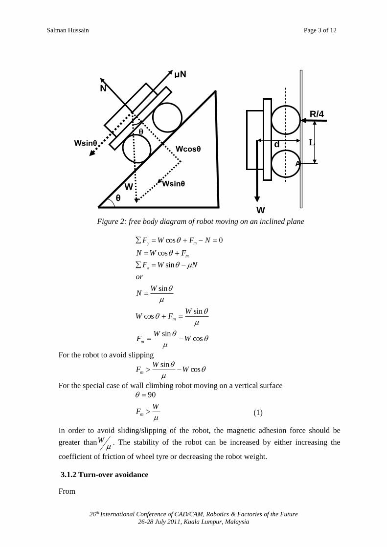
Use of the concentrating back plate (flux concentrator) shows a significant increase in
magnetic adhesion as the value jumps from 1000N to 1835N, thus almost doubling the
magnetic adhesion.
The air gap refers to the distance between the face of the magnet and the wall. As this gap
is increased, the magnetic adhesion decreases. This air gap is necessary to avoid obstacles
in some cases and to avoid friction in all the cases. The friction at the wheel is desirable,
but the friction at adhesion surfaces is not desirable.
4.4 Effect of wall thickness
For a specifc magnet, the wall thickness determines the ahdesion force. Simulations were
carried out with a N52 magnet. The wall material used was structural steel. The adhesion
force is minimum at a wall thickness of 0.1mm. When the thickenss of the wall is
increased from 0.1mm to 1mm, the adhesion force increases gradually. At 1 mm, the
magnetic flux is almost maximum. Any further increase in wall thickness does not have
considerable effect on adhesion force as shown in Figure 9.
Figure 10: Effect of air gap on different magnets having different strength
Salman Hussain Page 10 of 12
26th International Conference of CAD/CAM, Robotics & Factories of the Future
26-28 July 2011, Kuala Lumpur, Malaysia
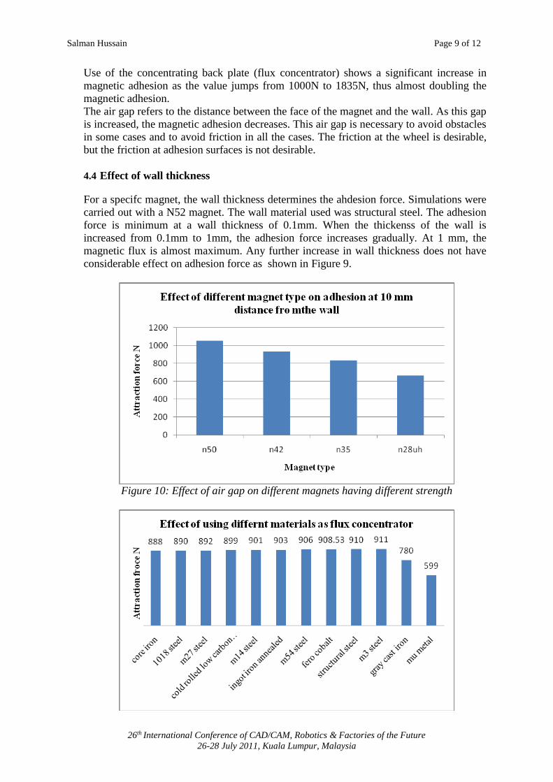
Figure 11: Effect of using different material for concentration plate (flux concentrator)
When using an air gap in the magnetic circuit, the stronger the magnet, the more adhesion
force it will produce as shown Figure 10. N28UH is the weakest material in the analysis
and thus producing the lowest adhesion force. N50, being the strongest magnetic force is
more desirable when circuit have air gaps.
4.5 Design of the flux concentrator
One of the major design considerations is the design of the flux concentrator. The
geometry and construction material of the concentration plate plays an important role in
optimizing the adhesion force. Figure 11 shows the variation of adhesion force, when
different materials are used for the flux concentrator. The adhesion force is minimum
when mu metal is used and maximum when structural steel is used. The use of a flux
concentrator also serves to provide strength to the chassis of the robot. So the use of
structural steel is desirable though the design will perform a trade-off to reduce the weight
of the climbing robot.
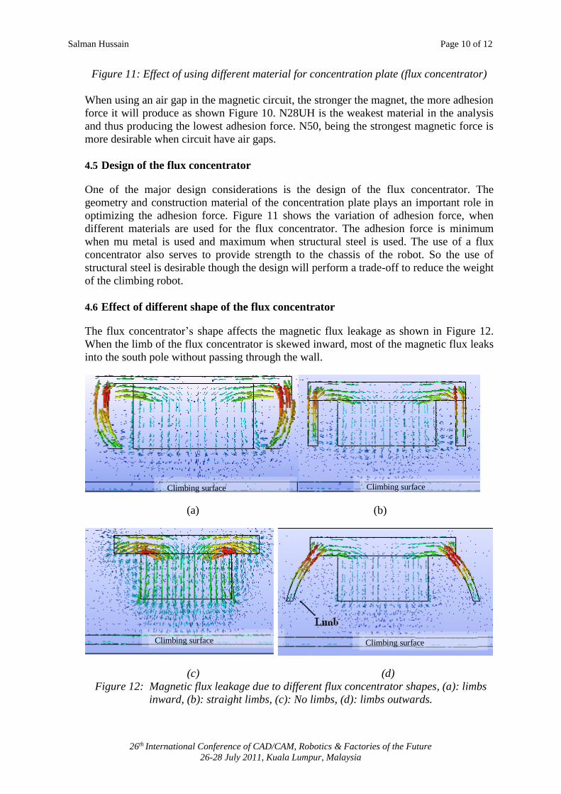
4.6 Effect of different shape of the flux concentrator
The flux concentrator’s shape affects the magnetic flux leakage as shown in Figure 12.
When the limb of the flux concentrator is skewed inward, most of the magnetic flux leaks
into the south pole without passing through the wall.
(a) (b)
(c) (d)
Figure 12: Magnetic flux leakage due to different flux concentrator shapes, (a): limbs
inward, (b): straight limbs, (c): No limbs, (d): limbs outwards.
Climbing surface
Climbing surface
Climbing surface
Climbing surface
Salman Hussain Page 11 of 12
26th International Conference of CAD/CAM, Robotics & Factories of the Future
26-28 July 2011, Kuala Lumpur, Malaysia
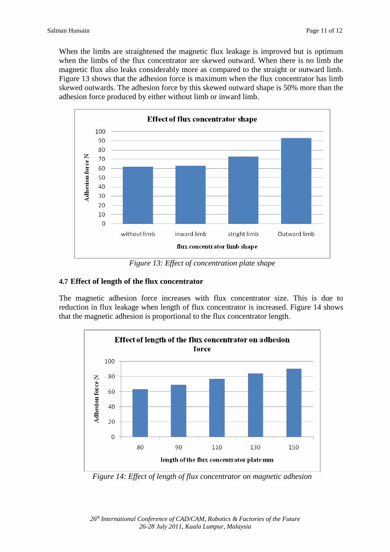
When the limbs are straightened the magnetic flux leakage is improved but is optimum
when the limbs of the flux concentrator are skewed outward. When there is no limb the
magnetic flux also leaks considerably more as compared to the straight or outward limb.
Figure 13 shows that the adhesion force is maximum when the flux concentrator has limb
skewed outwards. The adhesion force by this skewed outward shape is 50% more than the
adhesion force produced by either without limb or inward limb.
Figure 13: Effect of concentration plate shape
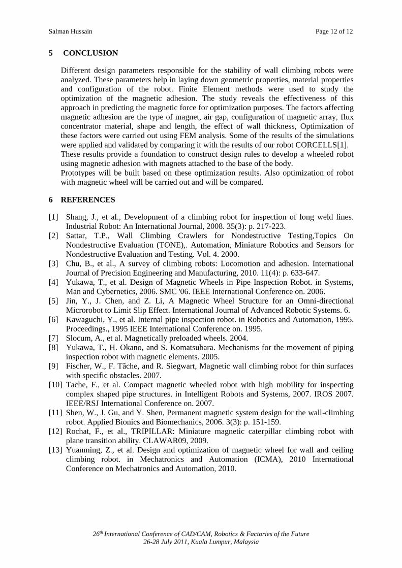
4.7 Effect of length of the flux concentrator
The magnetic adhesion force increases with flux concentrator size. This is due to
reduction in flux leakage when length of flux concentrator is increased. Figure 14 shows
that the magnetic adhesion is proportional to the flux concentrator length.
Figure 14: Effect of length of flux concentrator on magnetic adhesion
Salman Hussain Page 12 of 12
26th International Conference of CAD/CAM, Robotics & Factories of the Future
26-28 July 2011, Kuala Lumpur, Malaysia
5 CONCLUSION
Different design parameters responsible for the stability of wall climbing robots were
analyzed. These parameters help in laying down geometric properties, material properties
and configuration of the robot. Finite Element methods were used to study the
optimization of the magnetic adhesion. The study reveals the effectiveness of this
approach in predicting the magnetic force for optimization purposes. The factors affecting
magnetic adhesion are the type of magnet, air gap, configuration of magnetic array, flux
concentrator material, shape and length, the effect of wall thickness, Optimization of
these factors were carried out using FEM analysis. Some of the results of the simulations
were applied and validated by comparing it with the results of our robot CORCELLS[1].
These results provide a foundation to construct design rules to develop a wheeled robot
using magnetic adhesion with magnets attached to the base of the body.
Prototypes will be built based on these optimization results. Also optimization of robot
with magnetic wheel will be carried out and will be compared.
6 REFERENCES
[1] Shang, J., et al., Development of a climbing robot for inspection of long weld lines.
Industrial Robot: An International Journal, 2008. 35(3): p. 217-223.
[2] Sattar, T.P., Wall Climbing Crawlers for Nondestructive Testing,Topics On
Nondestructive Evaluation (TONE),. Automation, Miniature Robotics and Sensors for
Nondestructive Evaluation and Testing. Vol. 4. 2000.
[3] Chu, B., et al., A survey of climbing robots: Locomotion and adhesion. International
Journal of Precision Engineering and Manufacturing, 2010. 11(4): p. 633-647.
[4] Yukawa, T., et al. Design of Magnetic Wheels in Pipe Inspection Robot. in Systems,
Man and Cybernetics, 2006. SMC '06. IEEE International Conference on. 2006.
[5] Jin, Y., J. Chen, and Z. Li, A Magnetic Wheel Structure for an Omni-directional
Microrobot to Limit Slip Effect. International Journal of Advanced Robotic Systems. 6.
[6] Kawaguchi, Y., et al. Internal pipe inspection robot. in Robotics and Automation, 1995.
Proceedings., 1995 IEEE International Conference on. 1995.
[7] Slocum, A., et al. Magnetically preloaded wheels. 2004.
[8] Yukawa, T., H. Okano, and S. Komatsubara. Mechanisms for the movement of piping
inspection robot with magnetic elements. 2005.
[9] Fischer, W., F. Tâche, and R. Siegwart, Magnetic wall climbing robot for thin surfaces
with specific obstacles. 2007.
[10] Tache, F., et al. Compact magnetic wheeled robot with high mobility for inspecting
complex shaped pipe structures. in Intelligent Robots and Systems, 2007. IROS 2007.
IEEE/RSJ International Conference on. 2007.
[11] Shen, W., J. Gu, and Y. Shen, Permanent magnetic system design for the wall-climbing
robot. Applied Bionics and Biomechanics, 2006. 3(3): p. 151-159.
[12] Rochat, F., et al., TRIPILLAR: Miniature magnetic caterpillar climbing robot with
plane transition ability. CLAWAR09, 2009.
[13] Yuanming, Z., et al. Design and optimization of magnetic wheel for wall and ceiling
climbing robot. in Mechatronics and Automation (ICMA), 2010 International
Conference on Mechatronics and Automation, 2010.