towards veri ed microkernels for real-time mixed … veri ed microkernels for real-time...
TRANSCRIPT
Towards Verified Microkernels forReal-Time Mixed-Criticality Systems
Bernard Blackham
A thesis in fulfilment of the requirements for the degree ofDoctor of Philosophy
School of Computer Science & EngineeringFaculty of Engineering
The University of New South Wales
March 2013

THE UNIVERSITY OF NEW SOUTH WALES Thesis/Dissertation Sheet
Surname or Family name: Blackham
First name: Bernard
Other name/s: Robert
Abbreviation for degree as given in the University calendar: PhD
School: Computer Science & Engineering
Faculty: Engineering
Title: Towards Verified Microkernels for Real-Time Mixed-Criticality Systems
Abstract 350 words maximum: (PLEASE TYPE)
Today's embedded systems are becoming increasingly complex. We are seeing many devices consolidate both mission-critical real-time subsystems with convenience functionality such as networking stacks and graphical user interfaces. For example, medical implants such as pacemakers now provide wireless monitoring and control; bugs within the wireless subsystem must not be able to affect the safety-critical real-time operations of the pacemaker. Traditionally, this is achieved by using multiple processors with limited communication channels. However, these extra processors add significant overheads of size, weight and power. The mixed-criticality design promises to mitigate these overheads by consolidating multiple subsystems onto a single CPU, but this entails both mission-critical and convenience functionality sharing the same processor. In order to enforce isolation between subsystems of differing criticalities, we require a trustworthy supervisor to mediate control over the processor and provide behavioural guarantees. In this thesis, we explore several ingredients required to construct a high-assurance mixed-criticality real-time system. We propose that the formal verification and design of the seL4 microkernel makes it highly suited as a trustworthy foundation for these systems. We show how to compute interrupt response time guarantees which complement seL4's guarantees of functional correctness. We also explore the design space for such microkernels, which must balance the competing goals of formal verification and real-time responsiveness. We investigate the limits of interrupt latency for non-preemptible microkernels, and question whether fully-preemptible kernels are necessary for low-interrupt latency applications. We show that C can achieve equivalent performance to hand-optimised assembly for performance-critical kernel code, thereby allowing such code to be formally verified using C verification frameworks and maintain trustworthiness. We also present a practical framework for applying the capabilities of model checkers and SMT solvers to reason about compiled binaries. This framework can automatically detect infeasible paths and compute loop bounds, increasing the accuracy and the trustworthiness of response time guarantees.
Declaration relating to disposition of project thesis/dissertation I hereby grant to the University of New South Wales or its agents the right to archive and to make available my thesis or dissertation in whole or in part in the University libraries in all forms of media, now or here after known, subject to the provisions of the Copyright Act 1968. I retain all property rights, such as patent rights. I also retain the right to use in future works (such as articles or books) all or part of this thesis or dissertation. I also authorise University Microfilms to use the 350 word abstract of my thesis in Dissertation Abstracts International (this is applicable to doctoral theses only). …………………………………………………………… Signature
……………………………………..……………… Witness
……….……………………...…….… Date
The University recognises that there may be exceptional circumstances requiring restrictions on copying or conditions on use. Requests for restriction for a period of up to 2 years must be made in writing. Requests for a longer period of restriction may be considered in exceptional circumstances and require the approval of the Dean of Graduate Research. FOR OFFICE USE ONLY
Date of completion of requirements for Award:
THIS SHEET IS TO BE GLUED TO THE INSIDE FRONT COVER OF THE THESIS
Originality Statement
‘I hereby declare that this submission is my own work and to the best of my knowledgeit contains no materials previously published or written by another person, or substantialproportions of material which have been accepted for the award of any other degree ordiploma at UNSW or any other educational institution, except where due acknowledge-ment is made in the thesis. Any contribution made to the research by others, with whomI have worked at UNSW or elsewhere, is explicitly acknowledged in the thesis. I alsodeclare that the intellectual content of this thesis is the product of my own work, exceptto the extent that assistance from others in the project’s design and conception or in style,presentation and linguistic expression is acknowledged.’
Signed
Date 28 March 2013
iii

Copyright Statement
‘I hereby grant the University of New South Wales or its agents the right to archive and tomake available my thesis or dissertation in whole or part in the University libraries in allforms of media, now or here after known, subject to the provisions of the Copyright Act1968. I retain all proprietary rights, such as patent rights. I also retain the right to usein future works (such as articles or books) all or part of this thesis or dissertation. I alsoauthorise University Microfilms to use the 350 word abstract of my thesis in DissertationAbstract International. I have either used no substantial portions of copyright material inmy thesis or I have obtained permission to use copyright material; where permission hasnot been granted I have applied/will apply for a partial restriction of the digital copy ofmy thesis or dissertation.’
SignedDate 1 October 2013
Authenticity Statement
‘I certify that the Library deposit digital copy is a direct equivalent of the final officiallyapproved version of my thesis. No emendation of content has occurred and if there areany minor variations in formatting, they are the result of the conversion to digital format.’
SignedDate 1 October 2013
v


For Pwar Pwar


Abstract
Today’s embedded systems are becoming increasingly complex. We are seeing many de-vices consolidate both mission-critical real-time subsystems with convenience functionalitysuch as networking stacks and graphical user interfaces. For example, medical implantssuch as pacemakers now provide wireless monitoring and control; bugs within the wire-less subsystem must not be able to affect the safety-critical real-time operations of thepacemaker. Traditionally, this is achieved by using multiple processors with limited com-munication channels. However, these extra processors add significant overheads of size,weight and power.
The mixed-criticality design promises to mitigate these overheads by consolidating multi-ple subsystems onto a single CPU, but this entails both mission-critical and conveniencefunctionality sharing the same processor. In order to enforce isolation between subsystemsof differing criticalities, we require a trustworthy supervisor to mediate control over theprocessor and provide behavioural guarantees.
In this thesis, we explore several ingredients required to construct a high-assurance mixed-criticality real-time system. We propose that the formal verification and design of the seL4microkernel makes it highly suited as a trustworthy foundation for these systems. We showhow to compute interrupt response time guarantees which complement seL4’s guaranteesof functional correctness. We also explore the design space for such microkernels, whichmust balance the competing goals of formal verification and real-time responsiveness. Weinvestigate the limits of interrupt latency for non-preemptible microkernels, and questionwhether fully-preemptible kernels are necessary for low-interrupt latency applications.
We show that C can achieve equivalent performance to hand-optimised assembly forperformance-critical kernel code, thereby allowing such code to be formally verified us-ing C verification frameworks and maintain trustworthiness.
We also present a practical framework for applying the capabilities of model checkers andSMT solvers to reason about compiled binaries. This framework can automatically detectinfeasible paths and compute loop bounds, increasing the accuracy and the trustworthinessof response time guarantees.
ix


Acknowledgements
They say it takes a village to raise a child. Likewise, it takes a research community toraise a PhD student. I have been fortunate to grow in the company of so many talentedindividuals within SSRG and NICTA, and a fantastic international community of systemsresearchers.
I am most grateful to my supervisor Gernot Heiser, for his ongoing guidance and support,asking the tough questions (“why?”), and his invaluable feedback throughout my candi-dature as a PhD student. Gernot’s high standards, his rational perspective on the world,and his practical focus, have significantly enriched me and my research.
Thanks must also go to my co-supervisor and colleague Yao Shi, who achieved someincredible feats in pulling together code under tight deadlines.
To David Greenaway, for many insightful discussions, proofreading, and for suggesting Ihave “more bezierness” in my diagrams.
To everyone in Gernot’s power management power and real-time “random fun” group(coined by Dan) for getting up obscenely early for group meetings, so that I didn’t haveto stay up obscenely late on the other side of the world.
To all my fellow research students and researchers in the lab, past and present: Aaron,Adrian, Andrew, Anna, David(s), Etienne, Justin, Matt, Raf, Tom, and many others, fortheir wonderful stimulating company.
To my family, for their unconditional love and support, no matter where life’s journeywould take me.
Finally, to Alysia for her ongoing encouragement, love and understanding, through themany sleepless nights and long days.
Thank you!
xi

List of Publications
Some of the ideas presented in this thesis have been published in the followingpapers.
Bernard Blackham, Yao Shi, and Gernot Heiser. Protected hard real-time: Thenext frontier. In Proceedings of the 2nd Asia-Pacific Workshop on Systems(APSys), pages 1:1–1:5, Shanghai, China, July 2011a. doi: 10.1145/2103799.2103801.
Bernard Blackham, Yao Shi, Sudipta Chattopadhyay, Abhik Roychoudhury, andGernot Heiser. Timing analysis of a protected operating system kernel. InProceedings of the 32nd IEEE Real-Time Systems Symposium, pages 339–348,Vienna, Austria, November 2011b. doi: 10.1109/RTSS.2011.38.
Bernard Blackham, Yao Shi, and Gernot Heiser. Improving interrupt responsetime in a verifiable protected microkernel. In Proceedings of the 7th EuroSysConference, pages 323–336, Bern, Switzerland, April 2012a. doi: 10.1145/2168836.2168869.
Bernard Blackham and Gernot Heiser. Correct, fast, maintainable – choose anythree! In Proceedings of the 3rd Asia-Pacific Workshop on Systems (APSys),pages 13:1–13:7, Seoul, Korea, July 2012. doi: 10.1145/2349896.2349909.
Bernard Blackham, Vernon Tang, and Gernot Heiser. To preempt or not to pre-empt, that is the question. In Proceedings of the 3rd Asia-Pacific Work-shop on Systems (APSys), pages 8:1–8:7, Seoul, Korea, July 2012b. doi:10.1145/2349896.2349904.
Bernard Blackham and Gernot Heiser. Sequoll: a framework for model checkingbinaries. In Proceedings of the 19th IEEE Real-Time and Embedded Technologyand Applications Symposium, Philadelphia, USA, April 2013.
xiii


Contents
Originality Statement iii
Copyright Statement v
Authenticity Statement v
Abstract ix
Acknowledgements xi
List of Publications xiii
List of Figures xix
1 Introduction 1
1.1 On meeting deadlines . . . . . . . . . . . . . . . . . . . . . . . . . . . 4
1.2 On correct operation . . . . . . . . . . . . . . . . . . . . . . . . . . . 5
1.3 Research contributions and thesis outline . . . . . . . . . . . . . . . . 6
2 Background 9
2.1 Real-time application domains . . . . . . . . . . . . . . . . . . . . . . 10
2.2 Designing trustworthy mixed-criticality systems . . . . . . . . . . . . 10
2.3 The worst-case execution time problem . . . . . . . . . . . . . . . . . 17
2.4 Estimating the worst-case execution time . . . . . . . . . . . . . . . . 19
2.5 Summary . . . . . . . . . . . . . . . . . . . . . . . . . . . . . . . . . 26
xv

CONTENTS
3 A preliminary WCET analysis of seL4 27
3.1 Overview . . . . . . . . . . . . . . . . . . . . . . . . . . . . . . . . . . 27
3.2 Related work . . . . . . . . . . . . . . . . . . . . . . . . . . . . . . . 29
3.3 seL4 design features . . . . . . . . . . . . . . . . . . . . . . . . . . . . 31
3.4 Analysis method . . . . . . . . . . . . . . . . . . . . . . . . . . . . . 33
3.5 Initial WCET results . . . . . . . . . . . . . . . . . . . . . . . . . . . 43
3.6 Experimental results . . . . . . . . . . . . . . . . . . . . . . . . . . . 44
3.7 Summary . . . . . . . . . . . . . . . . . . . . . . . . . . . . . . . . . 48
4 Formal verification vs interrupt latency 51
4.1 Overview . . . . . . . . . . . . . . . . . . . . . . . . . . . . . . . . . . 51
4.2 Design considerations . . . . . . . . . . . . . . . . . . . . . . . . . . . 52
4.3 Areas of improvement . . . . . . . . . . . . . . . . . . . . . . . . . . 56
4.4 L1 cache pinning . . . . . . . . . . . . . . . . . . . . . . . . . . . . . 67
4.5 Analysis method . . . . . . . . . . . . . . . . . . . . . . . . . . . . . 68
4.6 Results . . . . . . . . . . . . . . . . . . . . . . . . . . . . . . . . . . . 71
4.7 Related work . . . . . . . . . . . . . . . . . . . . . . . . . . . . . . . 77
4.8 Summary . . . . . . . . . . . . . . . . . . . . . . . . . . . . . . . . . 79
5 Interrupt latency in non-preemptible kernels 81
5.1 Overview . . . . . . . . . . . . . . . . . . . . . . . . . . . . . . . . . . 81
5.2 Related work . . . . . . . . . . . . . . . . . . . . . . . . . . . . . . . 83
5.3 A non-preemptible kernel . . . . . . . . . . . . . . . . . . . . . . . . . 84
5.4 A fully-preemptible kernel . . . . . . . . . . . . . . . . . . . . . . . . 93
5.5 Results and analysis . . . . . . . . . . . . . . . . . . . . . . . . . . . 98
5.6 Conclusion . . . . . . . . . . . . . . . . . . . . . . . . . . . . . . . . . 103
6 Checking properties on binaries 105
6.1 Overview . . . . . . . . . . . . . . . . . . . . . . . . . . . . . . . . . . 105
6.2 Background . . . . . . . . . . . . . . . . . . . . . . . . . . . . . . . . 107
6.3 The problem . . . . . . . . . . . . . . . . . . . . . . . . . . . . . . . . 109
6.4 Anatomy of sequoll . . . . . . . . . . . . . . . . . . . . . . . . . . . . 111
xvi
CONTENTS
6.5 Evaluation . . . . . . . . . . . . . . . . . . . . . . . . . . . . . . . . . 123
6.6 Discussion . . . . . . . . . . . . . . . . . . . . . . . . . . . . . . . . . 127
6.7 Summary . . . . . . . . . . . . . . . . . . . . . . . . . . . . . . . . . 128
7 Automated infeasible path detection 131
7.1 Overview . . . . . . . . . . . . . . . . . . . . . . . . . . . . . . . . . . 131
7.2 Motivating example . . . . . . . . . . . . . . . . . . . . . . . . . . . . 133
7.3 Background . . . . . . . . . . . . . . . . . . . . . . . . . . . . . . . . 133
7.4 Details . . . . . . . . . . . . . . . . . . . . . . . . . . . . . . . . . . . 137
7.5 Evaluation . . . . . . . . . . . . . . . . . . . . . . . . . . . . . . . . . 143
7.6 Related work . . . . . . . . . . . . . . . . . . . . . . . . . . . . . . . 147
7.7 Summary . . . . . . . . . . . . . . . . . . . . . . . . . . . . . . . . . 149
8 A look at verification and performance 151
8.1 Overview . . . . . . . . . . . . . . . . . . . . . . . . . . . . . . . . . . 151
8.2 Related work . . . . . . . . . . . . . . . . . . . . . . . . . . . . . . . 153
8.3 Microkernel IPC . . . . . . . . . . . . . . . . . . . . . . . . . . . . . . 154
8.4 Optimisation techniques . . . . . . . . . . . . . . . . . . . . . . . . . 158
8.5 Evaluation . . . . . . . . . . . . . . . . . . . . . . . . . . . . . . . . . 163
8.6 Discussion . . . . . . . . . . . . . . . . . . . . . . . . . . . . . . . . . 164
8.7 Summary . . . . . . . . . . . . . . . . . . . . . . . . . . . . . . . . . 166
9 Conclusion 169
9.1 Summary . . . . . . . . . . . . . . . . . . . . . . . . . . . . . . . . . 169
9.2 Contributions . . . . . . . . . . . . . . . . . . . . . . . . . . . . . . . 170
9.3 Future work . . . . . . . . . . . . . . . . . . . . . . . . . . . . . . . . 171
References 173
xvii


List of Figures
1.1 Comparison of traditional and consolidated design models. . . . . . . 2
1.2 Formal verification, OS design and real-time . . . . . . . . . . . . . . 3
2.1 Putting latency into perspective . . . . . . . . . . . . . . . . . . . . . 11
2.2 The many faces of execution time . . . . . . . . . . . . . . . . . . . . 18
3.1 Workflow used to analyse seL4 . . . . . . . . . . . . . . . . . . . . . . 36
3.2 Error between estimated and real execution time . . . . . . . . . . . . 42
4.1 Pseudo-code of scheduler implementing lazy scheduling . . . . . . . . 58
4.2 Pseudo-code of scheduler without lazy scheduling . . . . . . . . . . . 58
4.3 Virtual address spaces managed using ASIDs . . . . . . . . . . . . . . 64
4.4 Virtual address spaces managed using shadow page tables . . . . . . 65
4.5 Example of a common seL4 design pattern . . . . . . . . . . . . . . . 72
4.6 Worst-case address decoding scenario . . . . . . . . . . . . . . . . . . 74
4.7 Overestimation of the hardware model . . . . . . . . . . . . . . . . . 76
4.8 Effect of enabling L2 cache and branch predictors . . . . . . . . . . . 78
5.1 Preemption point using enable/disable interrupts . . . . . . . . . . . 85
5.2 Preemption point using polling . . . . . . . . . . . . . . . . . . . . . 86
5.3 Preemption point using software-emulated polling . . . . . . . . . . . 87
5.4 WCET computed for all preemption points in seL4 . . . . . . . . . . 99
5.5 Worst-case response time of seL4, QNX and hypothetical limits . . . 102
6.1 Impact of infeasible path information on computed WCET of seL4 . . 106
6.2 Bit counting—the motivating example for sequoll . . . . . . . . . . . 110
xix

LIST OF FIGURES
6.3 Overview of sequoll . . . . . . . . . . . . . . . . . . . . . . . . . . . . 111
6.4 An example of instruction semantics from the ARM formalisation . . 113
6.5 Control flow graph of the code in Figure 6.2 . . . . . . . . . . . . . . 115
6.6 An example where constant propagation saves the day . . . . . . . . 117
6.7 Reduced control flow graph of Figure 6.5 . . . . . . . . . . . . . . . . 119
7.1 The typical double diamond is forever . . . . . . . . . . . . . . . . . . 132
7.2 The 3-diamond motivates our infeasible path detection work . . . . . 133
7.3 3-diamond control flow graphs are way cooler . . . . . . . . . . . . . 134
7.4 Outline of our infeasible path detection algorithm . . . . . . . . . . . 138
7.5 An example CFG with nested loops . . . . . . . . . . . . . . . . . . 140
7.6 An example of φ-elimination . . . . . . . . . . . . . . . . . . . . . . 141
7.7 An example of C code which is improved by φ-elimination . . . . . . 141
7.8 WCET improvement with automated infeasible path detection . . . . 144
7.9 Comparison of automated algorithm with manual efforts . . . . . . . 145
8.1 Anatomy of a fastpath “Call” operation . . . . . . . . . . . . . . . . 155
8.2 Execution time of IPC slowpath vs fastpath . . . . . . . . . . . . . . 156
8.3 Control flow graph of the seL4 slowpath and fastpath . . . . . . . . . 157
8.4 An example of C code without lifting optimisation . . . . . . . . . . 161
8.5 An example of C code with lifting optimisation . . . . . . . . . . . . 161
8.6 Generated assembly without lifting optimisation . . . . . . . . . . . 161
8.7 Generated assembly with lifting optimisation . . . . . . . . . . . . . . 161
8.8 Results obtained for one-way IPC after optimisations . . . . . . . . . 163
xx

Chapter 1
Introduction
Embedded systems are ubiquitous today—we interact with them without even know-
ing. We entrust our lives to many of these embedded systems such as medical im-
plants, industrial automation controllers, engine controllers and avionics systems.
These are hard real-time high-criticality systems, where failure is unacceptable and
may lead to loss of life.
The safe operation of these systems depends on the functional correctness of the
software and the timeliness of its responses. Such systems must be able to react
to asynchronous events from external stimuli within a specific deadline, regardless
of any other activities currently executing. For example, airbag controllers in a
car must reliably deploy an airbag within milliseconds of an impact being detected;
similarly, pacemakers must be able to deliver precisely timed electrical pulses to the
heart.
As these systems are becoming increasingly important in our daily lives, the man-
ufacturers of these systems also seek to gain a competitive advantage by adding
convenience features to their devices. For example, many embedded devices today
incorporate wireless and Bluetooth networking stacks, and run a built-in web server
for configuration. This extra functionality adds a significant amount of complexity
and code, and is not critical to the system’s primary function. It is important that
these low-criticality subsystems are unable to interfere with the correct operation of
high-criticality subsystems.
This is achieved most easily by separating high- and low-criticality subsystems onto
different CPUs, with limited communication channels. However, this leads to in-
1

CHAPTER 1. INTRODUCTION
Hardware bus
RT App
CPU
RTOS
App App
CPU
OS kernel
RTOS
App App
CPU
IPC
RT App
IPC
Microkernel/hypervisor
Figure 1.1: Traditional system designs (left) isolate real-time components onto sep-arate processors. A trustworthy microkernel or hypervisor (right) can beused to provide strong isolation between trusted and untrusted componentsexecuting on a single processor.
creased size, weight and power consumption (SWaP), as well as greater cost and
design complexity. A prominent example of these concerns can be seen in modern
cars, which have to up 100 CPUs, each dedicated to specific subsystems or tasks
(Broy et al., 2011).
Mixed-criticality systems offer a path to reduce design and production costs, whilst
improving software reuse. The key idea, illustrated in Figure 1.1, is to consolidate
both high- and low-criticality subsystems onto a single processor. Doing so can pro-
mote software reuse, simplify communication between subsystems, ease debugging
and thus speed up development.
The challenge in creating mixed-criticality systems is ensuring that the behaviour of
a low-criticality component is unable to affect the correct operation of high-criticality
components. Low-criticality components may be faulty due to software bugs or could
have been maliciously compromised. Mixed-criticality systems must be constructed
with strong guarantees of isolation between components—in particular, preserving
the behaviour of high-criticality components in all circumstances.
In this thesis, we explore various aspects of building hard real-time mixed-criticality
systems that provide strong guarantees of isolation. We build upon prior work on the
seL4 microkernel (Klein et al., 2009b) which is able to give guarantees of functional
isolation backed by the strength of machine-checked mathematical proof. Functional
isolation ensures that components cannot interfere with the memory or other state
2

Formal Verification
OS Design Real-time
Figure 1.2: This thesis explores the interaction between formal verification, operatingsystem design, and real-time requirements, and how to combine them tobuild trustworthy mixed-criticality systems.
of one another. However, it does not address the interactions between components
caused by their effects on execution time.
We focus this thesis on the ability to provide usable guarantees on the timing be-
haviour of a mixed-criticality system, without compromising functional isolation.
We do not address total temporal isolation between components—in particular, a
malfunctioning high-criticality component may be able to affect a low-criticality
component. Nor do we address the possibility of covert communication channels,
although the results from our work are essential to addressing these concerns.
Instead, this thesis is concerned with ensuring that high-criticality real-time sub-
systems are able to meet their deadlines, regardless of the actions of low-criticality
subsystems. In particular, we look at measuring and managing the worst-case in-
terrupt latency of the operating system (OS) kernel. We examine how aspects of
formal verification interact with the worst-case interrupt latency of a system, and
how these demands influence kernel design (Figure 1.2). Finally, we investigate
whether average-case performance is degraded by the needs of formal verification.
We limit our investigation and analysis to uniprocessor systems, choosing to delve
deeper into the design of such systems, rather than attempting to address the wide
array of complexities introduced by multiple processors. Multiprocessor systems add
3
CHAPTER 1. INTRODUCTION
additional concerns for analysing both worst-case execution time and proving strong
correctness guarantees through formal methods. We build upon a rich foundation
of prior work towards high-assurance real-time uniprocessor systems, which is not
yet as mature or as advanced for their multiprocessor counterparts.
1.1 On meeting deadlines
Real-time systems are characterised by the need to complete their computations
within specific deadlines. They can be broadly categorised according to the severity
of the consequences of missing a deadline, as follows:
• hard real-time: missing any deadline is catastrophic, resulting in complete
system failure;
• soft real-time: missing some deadlines can be tolerated—each missed deadline
results in degraded system performance; and
• best-effort (not real-time): such systems have no strict deadlines which affect
the operation of the system.
Systems traditionally dedicate individual processors to real-time tasks (sometimes
referred to as a federated design). With no other tasks executing on the processor
which could interfere, it is reasonably easy to guarantee that real-time deadlines
are met. In mixed-criticality systems, this is no longer true: there will almost
certainly be lower-criticality tasks executing which may affect real-time performance.
In particular, these lower-criticality tasks may induce the kernel to disable interrupts
for prolonged periods of time. It is the responsibility of the system designer to ensure
that these non-interruptible periods do not compromise the real-time components.
In an event-driven system where external interrupts initiate any activity, the OS
kernel plays a significant role in ensuring that real-time deadlines are met. The
kernel must provide guarantees on the worst-case interrupt latency—i.e. the longest
possible length of time between the arrival of an external interrupt and the execution
of its respective interrupt handling routine. In general, this is determined by two
factors: (1) the longest duration for which interrupts are disabled on the CPU, and
(2) the execution time of the code performing interrupt delivery. Both of these can
be determined using techniques for analysing worst-case execution time (WCET).
4
1.2. ON CORRECT OPERATION
In this thesis, we consider the mixed-criticality model, and assume that lower-
criticality tasks may be malicious (e.g. they may be compromised and therefore
execute arbitrary code). It should be possible to guarantee that even if a compo-
nent is compromised, components at higher criticality levels remain unaffected and
continue to meet their deadlines. This depends on having safe upper bounds on the
worst-case execution time of the kernel, which we address in Chapter 3.
1.2 On correct operation
A kernel which can guarantee that real-time deadlines are met is useless if it mal-
functions, crashes, or is compromised. In particular, in our threat model of mixed-
criticality real-time systems with compromised components, we must expect that an
attacker will attempt to exploit any bugs in the system. This is not unreasonable
given, for example, recent exploits demonstrated on modern cars by Checkoway et al.
(2011), who were able to gain control over key components (including the engine
and brakes) via the CD player, Bluetooth wireless and even over a GSM connection.
To this end, we require not only a kernel with sound temporal guarantees, but also
one that provides strong guarantees of functional correctness and isolation.
In order to build high-assurance mixed-criticality systems, the trusted computing
base must be kept as small as possible. The trusted computing base refers to the
set of all components (both hardware and software) which are critical to the correct
operation of the system. In particular, a bug in the trusted computing base can
compromise the security or reliability of the system. We assert that for mixed-
criticality systems, the OS responsible for enforcing isolation must be kept as small
as possible—a notion shared by the design concepts of microkernels (Liedtke, 1995),
microvisors (Heiser and Leslie, 2010) and exokernels (Engler et al., 1995).
seL4 (Klein et al., 2009b) is a third-generation microkernel, broadly based on the
concepts of L4 (Liedtke, 1995). It provides familiar OS abstractions such as vir-
tual address spaces, threads, synchronous and asynchronous communication, and
capabilities (Dennis and Van Horn, 1966) for access control and confinement.
The distinguishing feature of seL4 is that it is the first general-purpose operating sys-
tem kernel to be formally verified, with a machine-checked formal proof that the C
code implementation adheres to the functional specification of the kernel. Recently,
the seL4 team have extended this proof to the compiled assembly code (Sewell et al.,
5

CHAPTER 1. INTRODUCTION
2013). There are some convenient byproducts of the correctness proofs—in partic-
ular, they additionally imply that seL4 will never perform a (functionally) unsafe
operation or crash due to a software error, and that all operations will eventually
terminate.
Built on top of the proof of functional correctness, are proofs that seL4 enforces
integrity (Sewell et al., 2011)—i.e. that the ability to modify any state of a component
is restricted to only those subsystems with the appropriate authority. When applied
to the context of mixed-criticality systems, this ensures that the functional behaviour
of a completely isolated component is unaffected by the actions of other software
running on the same CPU.
The work presented in thesis leverages seL4’s ability to provide strong isolation
and functional correctness guarantees. Acceptable real-time performance was a key
design goal of seL4. However, this was not quantified until we performed a worst-
case execution time analysis of seL4, as described in Chapter 3. The results of
our analysis showed that seL4 required several improvements to make it suitable
for industrial real-time applications. Our efforts to improve seL4’s real-time per-
formance were constrained by the demands of formal verification. We explore the
compromises between real-time performance and formal verification in Chapter 4.
We also demonstrate in Chapter 5 that by forgoing the requirements imposed by
formal verification, we can reduce latencies even further, without the need for a
fully-preemptible kernel design and still maintain high levels of assurance.
1.3 Research contributions and thesis outline
By combining a sound response time analysis with isolation and correctness guar-
antees that are backed by the strength of mathematical proof, we can create a
trustworthy platform for building high-performance mixed-criticality hard real-time
systems with unprecedented levels of confidence. This is the overarching goal of the
work contained herein.
The structure of this thesis is aligned with the key research contributions to achieve
this goal. These contributions are the following:
• We successfully compute the WCET of the complete seL4 microkernel—the
6
1.3. RESEARCH CONTRIBUTIONS AND THESIS OUTLINE
first such published WCET analysis of any protected general-purpose operat-
ing system kernel. (Chapter 3)
• We examine the trade-offs between achieving good interrupt response times
and formal verification of microkernels, as part of a case study in improving
the interrupt response time of the seL4 microkernel. (Chapter 4)
• We investigate the limits of how low interrupt response times can be reduced
within a non-preemptible kernel, and compare it to what may be possible with
a fully-preemptible kernel. (Chapter 5)
• We apply model checking to executable binaries, to automatically compute
upper bounds on the iteration count of loops, and to prove (or disprove) specific
properties given by the user. (Chapter 6)
• We demonstrate a new technique to automate much of the labour-intensive,
error-prone manual annotation work that is required to achieve tight upper
bounds on the worst-case execution time. (Chapter 7)
• We show that performance-critical code, such the as IPC fastpath used in
seL4, can be implemented in C rather than assembly, without incurring any
significant performance penalty, and remain amenable to formal verification.
(Chapter 8)
7


Chapter 2
Background
This thesis presents several different but related aspects of designing and analysing
trustworthy, mixed-criticality, real-time systems. In this chapter, we give an overview
of the broader area of mixed-criticality systems and their trustworthiness for mission-
critical real-time applications, as well as the worst-case execution time problem.
Additionally, each chapter will also give a more specific overview of related work to
contextualise the material presented therein:
• Section 3.2 gives an overview of past WCET analyses of real-time operating
systems code.
• Section 4.7 looks at previous work in the area of formal verification and kernel
design of real-time systems.
• Section 5.2 focuses specifically on previous work towards analysing and imple-
menting preemptibility in OS kernels.
• Section 6.2 highlights previous work on static analysis of binaries, including
control flow graph reconstruction and loop bound computation.
• Section 7.6 reviews previous work on infeasible path detection for WCET anal-
yses.
• Section 8.2 summarises previous work on using higher level languages for
micro-optimisations.
9
CHAPTER 2. BACKGROUND
2.1 Real-time application domains
Real-time systems are required in many different application domains. A common
feature of all real-time systems is that they demand guaranteed upper bounds on
response time. However, the magnitude of this bound is application-dependent and
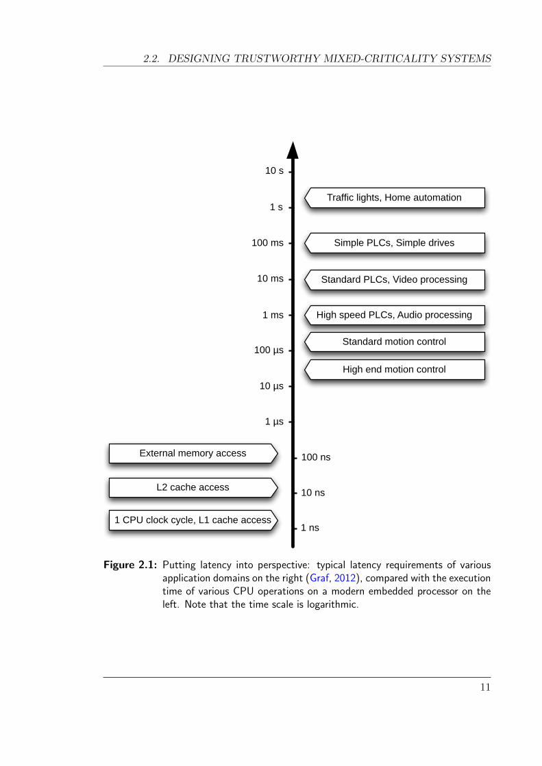
can vary significantly. For example, as outlined in Figure 2.1, industrial automation
systems requiring motion control may need response times in the order of tens of
microseconds, while systems such as traffic light controllers can tolerate response
times in the order of seconds. Many industrial applications are controlled using
programmable logic controllers (PLCs), which are dedicated hard real-time systems
designed for interfacing with physical sensors and actuators. The typical response
times expected from these can be as low as one millisecond.
As Figure 2.1 shows, there is a difference of several orders of magnitude between
the clock speeds of modern embedded processors (nanoseconds) and the latency
requirements of high-end real-time applications (tens of microseconds). However,
designing a system that can guarantee a given response time requires careful thought
and analysis. In particular, as memory access times are 1-2 orders of magnitude
slower than CPU speeds, it is easy to unknowingly write code with long latencies
(in particular, long worst-case latencies).
This thesis focuses on creating real-time systems covering the full range of possi-
ble application domains. As such, we ultimately target the 10–100µs end of the
spectrum (in Chapter 5), and explore what is required to reach this goal, without
compromising on trustworthiness.
2.2 Designing trustworthy mixed-criticality systems
Mixed-criticality real-time systems consolidate mission-critical with less critical func-
tionality on a single processor, in order to reduce cost, weight and power consump-
tion, and improve software re-use. Examples include the integrated modular avionics
architecture (ARINC, 2012), and the integration of automotive control and conve-
nience functionality with infotainment (Hergenhan and Heiser, 2008).
In a typical mixed-criticality system, the high-criticality components contain at most
10 000 to 100 000 lines of code. In comparison, the low-criticality components may
have millions of lines of code, and it is unrealistic to certify these components to the
10
2.2. DESIGNING TRUSTWORTHY MIXED-CRITICALITY SYSTEMS
100 ns
1 µs
100 µs
1 ms
10 ms
100 ms
1 s
10 s
10 µs
10 ns
1 ns1 CPU clock cycle, L1 cache access
L2 cache access
External memory access
High end motion control
Standard motion control
High speed PLCs, Audio processing
Standard PLCs, Video processing
Simple PLCs, Simple drives
Traffic lights, Home automation
Figure 2.1: Putting latency into perspective: typical latency requirements of variousapplication domains on the right (Graf, 2012), compared with the executiontime of various CPU operations on a modern embedded processor on theleft. Note that the time scale is logarithmic.
11
CHAPTER 2. BACKGROUND
same level as high-criticality ones. Safely consolidating both high- and low-criticality
components on the same processor demands strong isolation.
This isolation is provided by a supervisory OS such as a microkernel or hypervisor.
Each component is encapsulated within an isolated address space, with protection
enforced by hardware mechanisms that are configured by the OS. As the supervisor
OS has full control over the system, it must be certified to at least the same level as
the highest-criticality component.
Design standards for both safety- and security-critical software are now encourag-
ing more pervasive use of formal methods throughout the design, development and
testing phases. For example, IEC 61508 dictates functional safety standards for var-
ious industry applications, and highly recommends model-based testing and formal
verification for systems requiring the highest level of safety integrity (Int, 1998).
Similarly, the NIST Common Criteria define a range of “Evaluation Assurance Lev-
els” from EAL1, for non-critical systems, up to EAL7, for mission-critical systems in
high-risk environments (NIST). Levels 5 to 7 require formal methods in the design,
verification and testing.
The push for formal methods stems from the potential dangers arising from faulty
software. In contrast to traditional empirical testing-based validation, formal meth-
ods can offer significantly stronger assurances. However, both formal methods and
traditional testing have associated financial costs for industry. In order to minimise
cost, these efforts should be focused only where they are required.
2.2.1 Fully-preemptible vs non-preemptible kernel models
A fundamental design issue for kernels is whether they should be constructed as
fully preemptible or non-preemptible.
The traditional real-time operating system (RTOS) design uses a fully-preemptible
kernel, which means that the kernel is “interruptible by default”—interrupts are ex-
pected to occur almost anywhere in the kernel. For code that cannot be interrupted
(e.g. code which accesses shared data structures), interrupts are explicitly disabled
to avoid preemption. In addition to accessing shared data, other uninterruptible
sequences include kernel entry and exit, interrupt dispatching and some hardware
accesses. On a multi-processor system, disabling interrupts is combined with spin
locks to prevent other CPUs from concurrently accessing data. Uninterruptible code
12

2.2. DESIGNING TRUSTWORTHY MIXED-CRITICALITY SYSTEMS
paths must be kept short in order to minimise the kernel’s interrupt latency.
The alternative design, referred to as non-preemptible, disables interrupts by default
while the kernel is executing, resulting in a much simpler kernel design and imple-
mentation, as concurrency issues are avoided. The resulting RTOS code is easier
to understand, debug and reason about. It also simplifies the process of formally
proving the functional correctness of the code, something that is presently consid-
ered infeasible for preemptible programs given their high levels of concurrency (Klein
et al., 2009b). The simplicity also tends to result in better average-case performance,
which is the reason this approach has traditionally been taken in L4 microkernels.
RTOS designers, even when targeting high-performance processors typically used for
protected-mode systems, aim to achieve worst-case interrupt latencies in the order of
tens of microseconds or less. While this allows for a fair amount of computation, it is
difficult (if not impossible) to design a practical RTOS where all system calls are so
short. However, the interrupt latency of non-preemptible kernels can be reduced by
adding preemption points in long-running kernel operations. At a preemption point,
if a pending interrupt is detected, the current operation is postponed so that the
interrupt can be handled. Preemption points introduce a limited and controlled form
of concurrency. The approach requires that kernel data structures be in consistent
states when a preemption occurs. Furthermore, the designer should ensure that the
interrupted operations are eventually completed, and that high interrupt rates do
not impede progress.
The fully-preemptible design makes sense for a classical, unprotected RTOS, where
most interrupts can be handled with minimal switching of state. Such RTOSes can
achieve interrupt latencies of up to a few hundred cycles. Hofer et al. (2009) have
achieved latencies bordering on the limits of the hardware by taking advantage of the
CPU’s interrupt dispatcher for scheduling. However, this was done at the expense of
any memory protection, as all threads execute in system mode. Real-time systems
are becoming increasingly complex, running large software stacks which are hard to
debug and assure when using a flat address-space model. Given these pressures, the
unprotected RTOS design is reaching its limit.
Mixed-criticality systems demand strong isolation between subsystems, which re-
quires trustable memory safety (typically provided by hardware-enforced memory
protection, but could be a software-based solution). It also entails that hardware
interrupts should be handled in userspace. As such, the factors influencing the de-
13

CHAPTER 2. BACKGROUND
sign of such a kernel are significantly different to an unprotected RTOS. We explore
this further in Chapter 4 and Chapter 5.
Furthermore, embedded processors are becoming faster, and latencies in the order
of 10 000 to 100 000 cycles are acceptable in many situations. For example, 1 GHz
processors are increasingly common on modern high-end embedded devices and can
execute 100 000 cycles in 100µs—adequate for many applications. Hence, a fully
preemptible kernel is generally not necessary to meet real-time requirements (ex-
cept where ultra-low latencies are required) provided that the kernel can deliver
reasonable interrupt latency guarantees.
In the fully-preemptible design, it is also much more difficult to reason formally
(or even informally) about the behavior of the kernel, and adds complexity to de-
velopment and testing. It requires very careful coding of the interrupt paths, and
defensively analysing that at every point in the kernel an interrupt cannot crash the
kernel or make its state inconsistent. It also degrades the average-case performance
of the kernel due to locking overheads, which in-turn consumes more power, thereby
reducing the battery life of portable devices.
Analysing concurrency issues within a fully-preemptible kernel is extremely chal-
lenging due to the explosion of possible interleavings to consider and the difficulty
in reproducing timing-related bugs. Formal verification of a fully-preemptible kernel
has not yet been achieved although there has been some progress (Feng et al., 2008;
Cohen et al., 2009; Baumann et al., 2012).
In addition to unprotected RTOSes and high-assurance kernels for mixed-criticality
systems, there exist monolithic operating systems such as Windows, Linux or Mac
OS. In such systems, kernel operations can execute for a long time. Under a non-
preemptible design, limiting the WCET would require a very large number of pre-
emption points, resulting in negligible gain over a preemptible approach due to the
added complexity. As such, monolithic kernels are typically fully-preemptible. How-
ever, such kernels are a poor choice for high-assurance mixed-criticality systems, as
their trusted computing base is in the order of millions of lines of code.
2.2.2 Event-triggered vs time-triggered system designs
Any real-time system is concerned with responding to external stimuli. There are
two broad categories of systems based on how they are designed to respond to these
14

2.2. DESIGNING TRUSTWORTHY MIXED-CRITICALITY SYSTEMS
stimuli, known as event-triggered systems and time-triggered systems (sometimes
referred to as state-based systems).
In an event-triggered system, external stimuli are delivered via an interrupt to the
CPU. Depending on the system software, the interrupt may be handled immediately,
or after some non-interruptible operation has completed. In either circumstance, the
CPU processes the interrupt as soon as possible. Viewed differently, the execution
of the CPU is governed largely in response to external stimuli. This is the common
approach used for building non-safety critical systems.
In contrast, a time-triggered system is driven by periodically monitoring (polling)
the state of some object, and taking action when changes in state are observed.
Time-triggered systems are governed by a fixed schedule, and provide significantly
more deterministic behaviour than event-triggered systems.
Kopetz (1991) gives a comparison between the two types of systems, based on clas-
sifying events as either predictable or chance events. The occurrence of predictable
events is a priori, and therefore the system designer can anticipate them and allo-
cate the required resources ahead of time. Chance events cannot be predicted, and
therefore neither can their occurrence be limited. To compensate for this, event-
triggered systems must introduce mechanisms to control the flow of such events,
such as buffers and low-pass filters. On the other hand, a time-triggered system
implicitly provides such flow control by design. This avoids the need for testing
scenarios with high rates of chance events. Such testing can only be done with
simulated loads for event-triggered systems, and still does not guarantee correct
behaviour under all possible loads.
Scheler and Schroder-Preikschat (2006) more recently analysed the design consider-
ations when choosing between time-triggered and event-triggered architectures for
real-time systems. They considered several non-functional requirements of event-
and time-triggered systems, and identified only two criteria where one gives an ad-
vantage over the other. They found that fault tolerance is much easier to provide
through replication on a time-triggered system, as the schedules of each replica
offer convenient synchronisation points. However, event-triggered systems provide
lower overall resource utilisation, particularly when some inputs to the system are
aperiodic or sporadic in nature.
Others have shown that it is possible to defer the decision of whether to use an
event-triggered or time-triggered model and still build the majority of the system,
15

CHAPTER 2. BACKGROUND
by using design patterns which can be applied to both models (Scheler and Schroder-
Preikschat, 2006; Lakhani and Pont, 2012).
In the context of mixed-criticality systems, although the reliability of high-criticality
systems can benefit from a predictable time-triggered solution, low-criticality sys-
tems are often comprised of large legacy event-triggered code bases which are not
immediately portable to a time-triggered architecture. As such, mixed-criticality
systems may need to support aspects of both.
Irrespective of the system design, whether time-triggered or event-triggered, a real-
time OS kernel must still provide timing guarantees in order for a complete system
schedulability analysis. The work presented in this thesis applies to either design.
2.2.3 Schedulability of mixed-criticality systems
The scheduling of tasks and subsystems plays a fundamental role in a mixed-
criticality systems, in order to guarantee that high-criticality tasks are given the
CPU time they require to meet their deadlines. A straightforward approach to
scheduling is to provide fixed allocations of CPU time on a static schedule. However,
this requires the use of pessimistic worst-case execution time estimates to ensure that
high-criticality tasks can always meet their deadlines. In practice, this leads to a
significantly underutilised system, as the worst cases are rarely experienced.
Vestal (2009) presented a technique to reclaim this spare capacity for lower-criticality
tasks for preemptive fixed-priority systems. He observed that tasks of higher crit-
icality levels require more conservatism in their WCET estimates (to satisfy certi-
fication requirements), and conversely, lower-criticality tasks can accept much less
conservative estimates. He proposed that for a system with L criticality levels, L
different sets of WCET estimates should be used. He presented methods to use this
information to obtain a more precise schedulability analysis with better utilisation.
Baruah et al. (2011) continued this work to derive an optimal method of assign-
ing priorities to tasks (i.e. to maximise the system’s utilisation, and still guarantee
schedulability of the system). Mollison et al. (2010) have investigated the issue of
mixed-criticality scheduling on multi-core systems, presenting a technique to pro-
vide temporal isolation between tasks of different criticality levels, whilst allowing
unutilised CPU time to be reallocated.
16

2.3. THE WORST-CASE EXECUTION TIME PROBLEM
Baruah and Fohler (2011) have investigated the resource utilisation issue of time-
triggered architectures, with a view to creating certifiably correct systems. Under a
strictly time-triggered system, constructing schedules for multiple criticalities is NP-
hard and therefore can only be done offline. This lack of run-time adaptability limits
the maximum utilisation of a system. They show that a modification to the time-
triggered paradigm known as mode change can ensure that real-time guarantees are
still met, and also improve resource utilisation to be on par with event-triggered sys-
tems. Similar to the idea of Vestal, described above, two different system schedules
are computed: a “certification” schedule, which uses conservative bounds to ensure
that all high-criticality tasks can be scheduled; and a “system-designer” schedule,
that uses more realistic worst-case estimates (for example, based on measurements),
and allows for fuller utilisation of the system. In case of overrunning a deadline
in system-designer mode, the system immediately switches to certification mode to
ensure that no high-criticality deadlines are missed.
The work presented in this thesis is largely independent of the scheduling approach
used by a system. However, the worst-case response times and execution times of
the kernel are vital inputs into any schedulability analysis for a mixed-criticality
system.
2.3 The worst-case execution time problem
The response time of a system is the time between an event arriving, and it being
processed (the precise definition of “processed” depends on the application domain).
In software-based systems the response time is governed by the time it takes for some
program or code to execute.1 Determining the worst-case response time requires
computing the worst-case execution time of the relevant code.
Figure 2.2 shows different aspects of “execution time”. Along the bottom of the
figure, are the various aspects of a program’s execution time which can be prac-
tically observed or measured. Due to the complexity of modern hardware, it is
difficult to predict precisely how long a program will take to execute. For a deter-
ministic program, there exists some worst-case hardware state, and similarly some
1 There are often hardware delays before the software running on a CPU is even notified of anevent, but such delays are outside the scope of this thesis. They are typically in the order of cycles,and so we assume they are negligible compared to the latencies required for software to respond.
17

CHAPTER 2. BACKGROUND
Safe lower bound
Best-caseexecution time
Longestobserved
time
Shortestobserved
time
Worst-caseexecution time
Safe upper bound
Execution time
Typicalexecution
time
Underestimation Overestimation
Observable
Computed estimates
Real but not always observable
Figure 2.2: Different aspects of a program’s execution time (not to scale)
best-case hardware state, which maximises or minimises the execution time, respec-
tively. These give rise to the worst-case and best-case execution times. Given an
exponential number of possible hardware states, the likelihood that we see the worst
or best case through random testing is extremely small. In fact, even knowing what
the cases are, it can be extremely difficult to deliberately manipulate the hardware
into the required state.
For trustworthy real-time systems, we do not necessarily need to know the true
WCET. It suffices to instead have a safe upper bound which is guaranteed to be at
least as large as the WCET. A hard real-time system must be designed to allow for
the safe upper bound. Clearly, if the safe upper bound is significantly larger than
the actual WCET, the CPU would remain largely under-utilised. The difference
between the actual worst-case and a safe upper bound may be referred to as tightness,
pessimism, conservatism or overestimation. Tighter safe upper bounds are desirable,
as they allow slower (and thus generally cheaper) hardware to be used, while still
guaranteeing that deadlines are met.
18
2.4. ESTIMATING THE WORST-CASE EXECUTION TIME
2.4 Estimating the worst-case execution time
The problem of estimating the worst-case execution time can be broken down into
two distinct subproblems (Li et al., 1995). The first involves analysing the program
and identifying control structures which may cause long execution times. This in-
cludes loop analysis, examining conditionals and analysing recursive function calls.
This behaviour is independent of the hardware architecture.
The second subproblem involves applying this knowledge to a specific microarchi-
tecture. The microarchitecture of a system includes the structure of the CPU, its
pipelines and all levels of caches and main memory. For a given code path, the
microarchitecture can introduce a wide variation in possible execution times de-
pending on the state of other parts of the system. On a simple microprocessor with
no caches, a simple pipeline and deterministic instruction execution times, there is
no “hidden state” which could affect the execution time of a program. As a result,
there is practically no variability in the total execution time of a given code path.
More complex architectures often include features to optimise the common case.
These features include:
• deep pipelines,
• instruction caches,
• data caches,
• virtual address translation (MMUs),
• branch prediction,
• speculative execution, and
• out of order execution
The introduction of these features make analysis of the worst case execution time
much more difficult, as all of these features rely on some hidden state within the
processor. An increase in hidden state causes an exponential growth in the number
of possible states the processor could potentially be in. To exhaustively enumerate
all possible hidden states quickly becomes infeasible.
19

CHAPTER 2. BACKGROUND
Such features also cause a large disparity between best and worst case execution
times. For example, data caches are often 10–100 times faster than memory accesses.
A safe WCET estimation must assume that memory accesses miss the data cache
unless it can prove otherwise.
Caches are the dominant cause of execution time variability in modern embedded
systems. Mehnert et al. (2002) show that the use of MMUs and address spaces for
isolation did not significantly affect the real-time behaviour of tasks, as the extent of
their impact was comparable to that of caches. Features such as branch predictors
and other pipeline interactions can be considered second-order effects in comparison.
Complex interactions between different hardware features can create timing anoma-
lies. Timing anomalies arise when an instruction on a code path has multiple possi-
ble execution times—specifically, they occur when a locally shorter execution time
leads to a longer execution time overall, and vice versa (Lundqvist and Stenstrom,
1999; Reineke et al., 2006). This means that it is not possible for analysis tools to
assume that locally maximising execution time of a given instruction will guarantee
the worst-case execution time overall. Instead, more state needs to be maintained
throughout the analysis in order to compute a safe upper bound. Cassez et al. (2012)
make the distinction between timing anomalies which exist in the hardware itself,
and those which arise only due to the hardware abstraction used.
2.4.1 Analysis techniques
Wilhelm et al. (2008) have published a comprehensive survey of WCET analysis
tools and techniques. In the following sections only the most relevant ideas are
summarised.
WCET analysis techniques can be categorised into three classes (Petters et al., 2007):
static analysis attempts to analyse the source code and/or compiled binary with-
out executing it. Using a model of the hardware’s timing properties, it com-
putes conservative estimates at each stage of the analysis in order give an
upper bound with absolute confidence.
measurement-based analysis attempts to exercise various code paths to find the
worst-case execution path and measure it on real hardware.
20
2.4. ESTIMATING THE WORST-CASE EXECUTION TIME
hybrid analysis combines both static analysis and measurement-based analysis in
order to mitigate issues with unreliable hardware models of modern complex
processors.
Safe upper bounds for WCET are generally computed using a combination of static
analysis techniques and measurements on real hardware to validate the timing model
and/or results (Kirner et al., 2005b; Petters et al., 2007; Seshia and Rakhlin, 2012).
WCET bounds based on measurements alone cannot be relied upon—for example,
measurement-based upper bounds stated for RTLinux (Yodaiken and Barabanov,
1997) were later shown to be invalid (Mehnert et al., 2001).
2.4.2 Static analysis based approaches
Static analysis encompasses a class of techniques used to analyse code without exe-
cuting it. For the purpose of analysing WCET, there are several different approaches
that all use static analysis. Each approach makes a trade-off between accuracy of
the analysis and complexity (or time taken to perform the analysis).
Computing the WCET of programs in general is undecidable, as it is equivalent to
solving the halting problem. However, by placing reasonable restrictions on pro-
grams, we can obtain a tractable problem. For example, by removing the use of
recursive functions, self-modifying code and unbounded loops, it can be shown that
such programs will always terminate (Kligerman and Stoyenko, 1986; Li and Malik,
1995).
As static analysis never executes code, it requires a model of the architecture the
code will be executed on. Such models are often constructed from information made
available by the device manufacturer. The accuracy of the result depends largely
on the accuracy of the model. Whilst static analysis methods give theoretically safe
bounds, an error in the model can invalidate the result and any safety guarantees
provided by it. As an example, Avison (2010) has found discrepancies in the timing
models given by one prominent CPU manufacturer.
Implicit path enumeration
The implicit path enumeration technique (IPET) uses a set of integer linear equa-
tions to describe the possible execution paths of a program. Li et al. (1995) first
21

CHAPTER 2. BACKGROUND
described this technique and it has since seen widespread use through the litera-
ture and in tools developed by industry (Colin and Puaut, 2001a; Ferdinand and
Heckmann, 2004; Gustafsson, 2000; Staschulat et al., 2006; Li et al., 2007).
In IPET, the program is first decomposed into a control flow graph of basic blocks.
The cost ci of executing each basic block can be determined for the processor archi-
tecture (or, at least a safe upper bound). A variable xi is defined as the number of
times a given block will be executed in the program. Variables are also created for
the execution count of each edge within the program. These variables are related by
structure-defined flow constraints: the execution count of each basic block is equal
to the sum of the execution counts of all incoming edges, and similarly for outgoing
edges. Extra flow constraints may be added by the user or other analysis tools to
eliminate infeasible paths.
Once a set of equations in xi have been established, the total cost function to be
maximised is the sum-product of each basic block and its execution count:
Execution Time =N∑i=1
cixi
Together, these form a standard integer linear programming (ILP) problem. Such
problems arise in many fields and there has been a significant amount of research
effort dedicated to solving ILP problems (Schrijver, 1986). Although solving ILP
problems is in general NP-hard, the equations derived from IPET are similar to
network-flow problems and therefore exhibit systematic structures which can be
solved reasonably quickly with modern ILP solvers (Li et al., 1995).
The IPET technique has been extended to accommodate features of modern em-
bedded processor architectures, including multi-level instruction and data caches
(Chattopadhyay and Roychoudhury, 2009) and branch prediction (Burguiere and
Rochange, 2006). It has also been used in conjunction with other methods, such as
abstract interpretation (described below), to refine the ILP equations and thus give
tighter WCET estimates.
IPET is the approach implemented by the Chronos tool (Li et al., 2006), which we
use for the WCET analyses in this thesis.
22
2.4. ESTIMATING THE WORST-CASE EXECUTION TIME
Abstract interpretation
Abstract interpretation provides a basis for creating safe approximations of programs
in order to analyse their properties (Cousot and Cousot, 1977). It is a technique
with a wide range of applications and is often used in compilers and other tools to
find bugs and analyse software. Applied to WCET analysis, abstract interpretation
can be used to provide a safe approximation of all possible cache states, pipeline
states or variable values that can occur at any point in a program (Theiling et al.,
2000). This technique is typically combined with IPET to compute a safe upper
bound on WCET.
At points in the control flow graph where two paths merge, the sets of possible states
(or values) are combined. Merging is necessary in order to manage the potentially
exponential number of states which the system may be in. However, this can lead
to significant overestimation, as contextual information associated with each state
is lost when merged. Without this context, the analysis may proceed to explore
bogus states after a merge, resulting in possible solutions which are infeasible in
practice. However, the analysis is still guaranteed to be safe—i.e. all possible states
and outcomes will be considered, and the result will never be smaller than the true
WCET.
Model checking
Model checking can be used to reason about the logical correctness of discrete sys-
tems. A model checker is a procedure which decides whether a given abstract model
of a system satisfies a specific property (Muller-Olm et al., 1999). There are two
types of model checkers: explicit-state model checkers explore individual states to
ensure a property always holds, whereas symbolic model checkers operate on sets
of states. In the symbolic approach, sets have a compact representation, typically
using binary decision diagrams (BDDs).
Applied to WCET analysis, a model checker can be used in several ways. Firstly,
it can be used to determine the longest path by checking a property such as “this
program will execute for no more than N cycles”. The WCET of a program is
computed by performing a binary search for the answer. Metzner (2004) notes that
using model checking for finding the longest path will not lead to more accurate
results than IPET, however it does overcome some limitations of IPET such as the
23
CHAPTER 2. BACKGROUND
numerical instability in some ILP problems.
Secondly, model checking can also be used to model the cache behaviour at different
program points. Unlike abstract interpretation, model checking does not overap-
proximate the set of states by abstracting details away. Model checkers only ever
deal with concrete states—if a solution is detected, it is guaranteed that it can be
realised on hardware (assuming the model itself is consistent with the hardware).
Dalsgaard et al. (2010) achieve both of the above in their tool METAMOC, by
framing the WCET problem as a network of timed automata in the UPPAAL sym-
bolic model checker (Behrmann et al., 2004). They produce independent models
of the CPU’s pipeline, its caches, external memory, and the executable being anal-
ysed. Loop bounds need to be manually provided as annotations on the executable.
These models are composed together using “synchronisation channels” into a com-
plete model on which UPPAAL computes a precise worst-case execution time.
Cassez (2011) uses some of the ideas from METAMOC, modelling the hardware and
program as timed automata, but instead frames the WCET problem as a “timed
two-player game”. Player one is the program whose goal is to terminate, and player
two is the hardware whose goal is to maximise the execution time of the program.
Using support for timed games in UPPAAL-TiGa (Behrmann et al., 2007), the model
checker finds the smallest time in which player one can “win” (terminate), regardless
of how the adverse hardware behaves. Cassez’s method also automatically performs
value analysis and computes loop bounds as part of the model, and demonstrates
better scalability than METAMOC.
Compared with IPET, these various approaches to model checking trade better accu-
racy for increased computational complexity. Huber and Schoeberl (2009) compare
both model checking and abstract interpretation, and suggest that model checking
is best suited to accurately computing results for basic blocks, while the overall
program WCET should be computed with IPET.
2.4.3 Measurement-based approaches
An obvious technique to calculate the worst-case execution time of a program is to
execute the program under all possible scenarios and measure the program’s exe-
cution time. However, all possible scenarios must accommodate all possible code
paths and all states of the system (including hidden states). As both programs and
24

2.4. ESTIMATING THE WORST-CASE EXECUTION TIME
processors typically have an exponentially large number of possible states, exhaus-
tively testing all of these is not possible. Measurement-based approaches determine
a subset of code paths and states to examine. It is very difficult to guarantee that
the selected subset covers the true worst-case bounds for the program and so the
WCET will always be underestimated. This makes it a risky approach for analysing
hard real-time systems where the missing a deadline is not permissible.
Whilst the number of paths and states becomes infeasible in the general case, nu-
merous approaches exist to contain the state explosion. Wenzel et al. (2005) propose
to partition loop-free programs into discrete units which can be analysed individu-
ally. Zolda et al. (2009) later extended this with support for loops and unstructured
code. However, this approach suffers from the issue that partitions of a program are
not completely independent. Deverge and Puaut (2005) explore how to eliminate
any interactions between different partitions, and assert that this requires support
from the compiler and comes at the expense of performance.
There are other techniques to improve measurement-based WCET analysis which
rely on some form of static analysis. These are classified as hybrid analyses and are
described in the following section.
2.4.4 Hybrid approaches
Hybrid approaches seek to gain some of the benefits of both static analysis and
measurement-based analysis. Such methods are typically targeted for soft real-time
systems. Kirner et al. (2005a) argue that hybrid analyses are much more realistic
and less likely to be undermined by modelling inaccuracies, compared with pure
static analysis.
Schaefer et al. (2006) present a hybrid approach called Potoroo, which seeks to
identify the worst-case execution time by analysing the execution time profile (ETP)
of a code path. An ETP represents a distribution of timings for a specific code
path. For such a path, the most significant factor contributing to execution time
on modern cache-based processors is the number of memory accesses that miss the
caches. Other sources of microarchitecture-specific variability, such as pipeline stalls
and branch mispredictions, can be considered second-order effects and of much less
significance than caches.
The Potoroo approach attempts to correlate predicted ETPs generated from static
25

CHAPTER 2. BACKGROUND
analysis with the measured ETPs from executing a code path. Given the set of cache
miss counts observed during execution of a program, Potoroo uses static analysis
to either confirm that it is in fact the largest number of cache misses possible,
or automatically construct a counterexample which can be executed and measured.
Although this technique is probabilistic as it assumes all non-cache related variations
to be negligible, it does lend some assurance that the WCET is in reality feasible.
Seshia and Rakhlin (2012) demonstrate a different hybrid approach to WCET mea-
surement called GameTime, based on game-theoretic online learning and systematic
test case generation. They decompose a loop-free program into “basis paths”, such
that all paths through the program can be represented as linear combinations of
the basis paths. In GameTime, the problem is modelled as a game between the
WCET-estimation algorithm and the hardware (the adversary). In this game, the
hardware is assumed to always hide the worst case if it can, and the algorithm is
challenged with finding these hidden cases. The approach is highly portable as it
discovers the platform’s timing model automatically. However, the resulting WCET
guarantees remain probabilistic and therefore may not be suitable for hard real-time
systems.
2.5 Summary
Both mixed-criticality system design and worst-case execution time analysis are
active research areas in their own right. This chapter has given a background on the
relevant aspects of each area, as they are both key ingredients in the construction
of trustworthy mixed-criticality real-time systems.
In the following chapters of this thesis, we build upon existing static analysis tools
for computing worst-case execution time, applying them to a verified OS kernel,
as well as improving infeasible path detection. We also explore the interactions of
kernel design, formal verification and real-time constraints, in order to develop a
high assurance real-time kernel that is suitable as a platform for a variety of mixed-
criticality real-time systems.
26
Chapter 3
A preliminary WCET analysis of seL4
This chapter is based on work published at RTSS 2011 in which I was the primary author
(Blackham, Shi, Chattopadhyay, Roychoudhury, and Heiser, 2011a). The analysis of the seL4
kernel was performed primarily by myself, with assistance from Yao Shi, and using analysis
software based upon the Chronos tool from the National University of Singapore. Some of
the text in Section 3.4.3 describing the functioning of Chronos was contributed by the paper’s
co-author Sudipta Chattopadhyay.
3.1 Overview
Mixed-criticality designs aim to reduce the hardware requirements of a system, com-
pared with their traditional federated counterparts. This is achieved by consolidat-
ing multiple components onto a single processor and trusting a supervisor such as
a microkernel or hypervisor to provide functional and temporal isolation between
critical real-time components and less critical time-sharing components. To support
hard real-time applications, the supervisor must provide safe upper bounds on its
interrupt latency.
Computing interrupt latency bounds on OS kernels is a task made difficult by their
unstructured code, tight coupling with hardware and sheer size. Their design, struc-
ture and implementation details determine how complex such an analysis will be.
For example, the interrupt latency of a well-designed fully-preemptible kernel can
be computed by evaluating a small subset of kernel paths independently. Non-
preemptible kernels require much longer code paths to be analysed. Unconventional
27
CHAPTER 3. A PRELIMINARY WCET ANALYSIS OF SEL4
control flow, as is common in OS kernels, can also significantly complicate the anal-
ysis.
We assert that using a microkernel-based design reduces the size and complexity of
the analysed code base. This makes them amenable to static analysis, whilst also
reducing the size of the trusted computing base, which is a desirable property for
mixed-criticality systems.
The seL4 microkernel is especially suited to high-reliability applications as it is for-
mally verified (Klein et al., 2009b). Formal machine-checked proofs guarantee not
only functional correctness, but also that all operations terminate, which is an es-
sential (and non-trivial) underpinning of any execution time analysis. Whilst these
strong guarantees are sufficient for many systems, the formal verification offers no
temporal guarantees required by real-time systems (other than eventual termina-
tion).
In this chapter, we present a case study of the seL4 microkernel and analyse its
worst-case execution time and thus interrupt latency, with a view to tuning the
kernel for hard real-time mixed-criticality applications. This case study is the first
published complete interrupt-response-time analysis of an OS kernel providing full
virtual memory and memory protection.
We show that realistic safe upper bounds on interrupt latencies can be determined
for protected microkernel-based systems. We perform a full context-aware WCET
analysis of all of seL4’s code paths on a modern embedded CPU architecture using
a realistic pipeline model. We identify several properties of seL4’s code that assist
in the analysis and make it possible to give tighter bounds on execution time. The
structure of seL4 helps to resolve many of the difficulties encountered in previous
analyses of kernels.
The analysis performs virtual inlining in order to be context-aware: each function
is analysed under different calling contexts, which provides much tighter bounds
on WCET. Such an approach is feasible due to seL4’s small code size (compared
with other protected operating system kernels), at around 8 700 lines of C code.
Despite this fact, it is, to our knowledge, still the largest code base where a full
context-aware WCET analysis has been performed. We also measure the identified
worst-case paths on real hardware, demonstrating that the WCET bounds obtained
are not overly pessimistic and can be used in practical systems.
Section 3.2 summarises the state of the art of WCET studies of operating systems
28

3.2. RELATED WORK
code. Section 3.3 details the properties of seL4 that make it amenable to auto-
mated analysis. Section 3.4 describes the methods and tools used to analyse seL4.
Section 3.5 gives some background on work performed to improve seL4’s temporal
behaviour. Section 3.6 shows the results of our analysis, highlighting the worst-case
execution paths found.
3.2 Related work
Several studies have been performed to compute the interrupt latency of operating
systems code, however none have successfully analysed a kernel providing memory
protection and full virtual memory support. The most relevant analyses of RTOS
kernels are summarised in this section.
RTEMS: The first major static WCET analysis of a real-time executive was pub-
lished by Colin and Puaut (2001b), who analysed the C source code of the RTEMS
operating system. Their version of RTEMS did not provide memory protection or
any form of virtual address spaces. They used a tree-based static analysis tool,
HEPTANE, targeting a Pentium processor. They encountered several issues such
as unstructured loops with goto statements and function pointers, which all had to
be resolved manually to complete the analysis.
The study was also faced with the problem of determining loop bounds which were
tied to the dynamic run-time state of the system. This includes factors such as the
number of tasks running, the structure of the system heap and the rate of interrupts.
As such, the WCET of the RTEMS kernel is heavily dependent on the construction
or design of the system in which it is used.
OSE: A WCET analysis of the microkernel used by the OSE delta operating sys-
tem was undertaken by Carlsson et al. (2002) and Sandell et al. (2004) using the
SWEET analysis tool (Gustafsson, 2000). OSE is widely used in embedded systems
including mobile phones and for industrial control applications. The OSE kernel
permits interrupts in most kernel code, except within 612 “disable-interrupt” re-
gions. Despite the complex control flow of the kernel, most of the disable-interrupt
regions were simple, well structured and free of function pointers, simplifying the
29
CHAPTER 3. A PRELIMINARY WCET ANALYSIS OF SEL4
analysis. Caches were not modelled in the analysis. The microkernel analysed did
not support memory protection.
µC/OS-II: Lv et al. (2009a) analysed the µC/OS-II kernel for the WCET of each
system call. They used the Chronos analysis tool to model a MIPS processor with an
L1 cache. The analysis was generally successful, but required a significant amount of
manual intervention. The µC/OS-II kernel also does not provide memory protection.
L4: Singal and Petters (2007) attempted an analysis on the L4 N1 kernel, which
does offer memory protection. They also found that unstructured code, inline as-
sembly and context switching contributed to making the analysis difficult. They
highlight the long execution paths associated with destroying kernel objects, due to
the nature of dynamic memory structures of the kernel. Safe WCET bounds were
never established.
Other studies: Lv et al. (2009b) have also conducted a survey of past WCET anal-
yses of real-time operating systems. Their survey highlighted the need for context-
specific WCET values, rather than a single absolute value, as well as a combined
kernel/application analysis. They concluded that tools were not sufficiently ma-
ture to permit tight WCET estimates on modern RTOS kernels on modern CPU
architectures.
What is a “tight” estimate depends on the application domain, which dictates how
much over-provisioning of the system is permissible. In analysing the seL4 micro-
kernel, we encountered overestimation of up to a factor of three, using state of the
art tools (Figure 4.7).
Most past WCET analyses of real-time operating systems have been assisted or
simplified by the designs of the kernels they were analysing. Our work is no different,
as we describe in the following section. This trend suggests that operating systems
code pushes the bounds of both WCET analysis techniques and in particular of
static analysis methods.
30

3.3. SEL4 DESIGN FEATURES
3.3 seL4 design features
The seL4 microkernel has several properties that assist with automated static anal-
ysis. First and foremost is that its code base is small. We analyse the ARM version
of the seL4 kernel, which has around 8 700 lines of C code and 887 lines of ARM
assembly code. The analysis is performed using a modified version of Chronos 4.1
(Li et al., 2007), adapted for the ARM architecture, and requires around four hours
to compute. The analysis is described further in Section 3.4.
seL4 is an event-based kernel—i.e. the kernel uses a single kernel stack irrespective
of which thread it is servicing. Context switching between threads is performed by
changing a variable pointing to the currently running thread. In contrast, process-
based kernels, with dedicated per-thread kernel stacks, switch the stack pointer dur-
ing a context switch. As a result, the entire call stack is invalidated, and execution
resumes based on the call stack from a prior context switch. We explore this fur-
ther in Section 4.2.1, but the key insight is that the event-based model aids static
analysis, as control flow is more structured.
The seL4 microkernel was designed from its inception to be formally verified. Al-
though the executable code is written in C, seL4 was initially developed in the
functional language Haskell, to support rapid prototyping and provide a common
ground for both the development team and verification team (Klein et al., 2009a).
From the Haskell prototype, the development team implemented a high-performance
C version, while the verification team mathematically formalised the expected be-
havior of the kernel into an abstract specification. The correctness of seL4 relies on
a chain of proofs that the C code implements the Haskell prototype, and that the
Haskell prototype conforms to the abstract specification.
As a result of this construction, the requirements of formal verification, as well as
the security-driven desire for strong resource isolation, the C implementation of seL4
exhibits a number of properties that simplified our analysis:
• seL4 never stores function pointers at run-time. This allows all branches to be
automatically resolved off-line (with the help of symbolic execution).
• seL4 never passes pointers to stack variables. This eliminates the possibility
of variables aliasing stack memory, simplifying the analysis of memory aliasing
for WCET.
31

CHAPTER 3. A PRELIMINARY WCET ANALYSIS OF SEL4
• The task of memory allocation is delegated to userspace, avoiding complex
allocation routines within the kernel. The kernel checks that regions do not
overlap but these checks are much simpler than the code for a complete allo-
cator.
• There are very few nested loops within seL4. Automatically identifying nested
loops at the assembly level and their loop relations is not an easy task, or even
well-defined, in the presence of heavy compiler optimisations.
• Most unbounded operations (such as object deletion) already contain explicit
preemption points. If an interrupt is pending at a preemption point, seL4 will
postpone the current operation and return up the call stack to a safe context
to handle the interrupt. There still remained some unbounded loops, which
we address in Section 3.5.
It is worth noting that many of these properties arose because of requirements of
the formal verification process, without any regard to a WCET analysis. Despite
the restrictions imposed by some of these properties, seL4 does not suffer a signifi-
cant performance penalty—its hot-cache IPC performance is as good as the heavily
optimised assembly IPC path found in the OKL4 2.1 microkernel (described further
in Chapter 8).
The specification of seL4 guarantees that the kernel will never enter an infinite loop—
i.e. all seL4 system calls eventually return to the user. This allows the analysis to
ignore any infinite loops that exist in the kernel. Such loops are executed when
assertions in the C code fail, however the proofs guarantee that these assertions are
always true (under the assumptions of the proof, which include a correct C compiler1
and the absence of hardware bugs).
One issue arising during our analysis of seL4 is that in two places mutually-recursive
functions are used. The formal proof guarantees termination, proving that the
functions do not recurse more than once. This knowledge simplifies the analysis, as
it allows us to simply virtually inline each function at most twice. However, for this
analysis, we choose to unwind the recursion manually.
1 Sewell et al. (2013) have recently demonstrated work that eliminates this assumption in seL4for binaries compiled with gcc’s -O1 optimisation level, and also potentially at higher optimisationlevels.
32

3.4. ANALYSIS METHOD
Lines of C code ∼8 700Lines of assembly code 887Number of C functions 316Number of loops 76
Code size (bytes) 42,120Number of instructions 10,271Number of functions 228Number of basic blocks 2,384Number of loops 56
Table 3.1: Properties of the analysed seL4 source code (left) and compiled binary(right)
In seL4’s event-based model, almost all functions return to their caller, making static
analysis simpler. However, this is not true in one specific code path: seL4 features
a highly optimised C routine for handling the most common IPC operations, known
as the IPC fastpath; it improves the average time for these IPC operations by an
order of magnitude. The fastpath, though in C, returns directly to userspace (using
an inlined assembly routine), avoiding the need for stack unwinding. The analysis
toolchain required some work to support this control flow as it previously assumed
that all functions would return to their caller.
Finally, seL4 is accompanied by a large body of machine-checked proofs which con-
tains thousands of invariants and lemmas. It should be possible to incorporate these
into a WCET analysis to assist in excluding many infeasible paths. They have not
been utilised in this analysis, but present an opportunity for future research.
Some interesting statistics of the analysed seL4 binary are summarised in Table 3.1.
3.4 Analysis method
We analyse the seL4 kernel binary to compute a safe upper bound on its interrupt
latency. For comparison, we construct scenarios to exercise the worst-case paths
detected by the analysis and executed them on real hardware. Together, these
indicate how closely the computed bounds reflect reality.
3.4.1 Processor model
seL4 can run on a variety of ARM architectures and platforms. For this analysis we
use the BeagleBoard-xM platform with a TI DM3730 processor. This processor has
an ARM Cortex-A8 core running at 800 MHz, with separate 32 KiB L1 instruction
33
CHAPTER 3. A PRELIMINARY WCET ANALYSIS OF SEL4
and data caches, both 4-way set-associative. Our analysis tools do not support
modelling the L2 cache.2 As a result, the L2 cache is also disabled in hardware for
our measurements.
The experiments were configured to use 128 MiB of physical memory. We measured
the latency of a read or write to physical memory on this platform to vary between
80–100 cycles; in the static analysis we assume a 100-cycle penalty for all cache
misses. The seL4 kernel locks its pages into the TLB so that there are no TLB
misses during execution.
The Cortex-A8 has a 13-stage dual-issue pipeline, with in-order issue, execution
and retirement. Most arithmetic instructions3 can be issued simultaneously with
a subsequent arithmetic instruction or memory load, provided that there are no
dependencies between them. Forwarding paths between stages permit single-cycle
instructions to execute without stalls arising from register dependencies. The com-
piled seL4 binary happens to use only those arithmetic instructions which can be
dual-issued—in particular, there are no multiplication or “rrx” operations which
would incur a multi-cycle latency. Our static analysis models the dual-issue nature
of the pipeline for arithmetic instructions.
All non-arithmetic instructions executed by the seL4 kernel fall into one of the
following categories:
• load/stores—these incur a 100 cycle memory access penalty on a cache miss
or with caches disabled;
• branches—these incur a 13 cycle penalty without prediction (see below);
• coprocessor operations mcr/mrc (move from coprocessor to register/move from
register to coprocessor)—these include cache flushing, TLB flushing and ad-
dress space switching which can take 120 cycles or more, depending on the
particular operation and the state of the system;
• synchronisation instructions isb/dsb (instruction synchronisation barrier/data
synchronisation barrier)—these instructions flush the instruction pipeline (13
cycles) or flush the CPU’s write buffers (29 cycles), respectively;
2 The analyses presented in Chapter 4 and Chapter 5 use a newer version of Chronos whichgained support for L2 cache analysis.
3On ARM the “arithmetic instructions” also include logical primitives. The full list is: ADC,ADD, AND, BIC, EOR, ORR, RSB, RSC, SBC, SUB, CMN, CMP, TEQ, TST, MOV and MVN.
34

3.4. ANALYSIS METHOD
• processor state changes (cps)—these take 60 cycles.
The Cortex-A8 also supports speculative prefetching and branch prediction. These
features were disabled in hardware in order to make measurements more determin-
istic, and were not included as part of the processor model.
The L1 caches on the Cortex-A8 have an unspecified random replacement policy.
This prevents simulation of the exact cache behavior, and effectively forces any safe
cache analysis to assume a direct-mapped 8 KiB cache. Furthermore, it makes it
infeasible to construct a true worst-case scenario on hardware, Thus we can only
determine an upper bound on the pessimism of our model.
3.4.2 Static analysis
We analyse seL4 for its interrupt latency by examining the worst-case execution
time of all possible paths through the kernel. A path through the kernel begins at
one of the kernel’s exception handlers, such as the system-call or page-fault handler.
A path ends when control is passed back to the user, or at the start of the kernel’s
interrupt handler code.
Being a non-preemptible kernel, seL4 disables interrupts at all times when executing
kernel code, but checks for pending interrupts at explicit preemption points (typi-
cally in long-running unbounded loops). If an interrupt is detected at a preemption
point, seL4 postpones the current operation and immediately handles the interrupt.
As preemption points occur only at the end of loop iterations, we account for them in
the analysis by forcing the iteration count of the loop to 1. The worst-case scenario
for a path including a preemptible loop occurs when an interrupt arrives immedi-
ately after entry to the kernel. The kernel will still execute the operation with one
iteration of the loop to ensure progress is made (avoiding livelock) and then handle
the interrupt.
Interrupts arriving during kernel execution are handled immediately prior to return-
ing to the user. The interrupt latency is therefore the sum of the WCET of any path
through the kernel up to this point, and the time taken to dispatch the interrupt to
a user thread.
The seL4 binary we analyse is compiled with gcc 4.5 (from CodeSourcery’s 2010.09
release) using the -O2 optimisation level and additionally the -fwhole-program flag,
35

CHAPTER 3. A PRELIMINARY WCET ANALYSIS OF SEL4
!"#$
%&'()*'+($
,%-.$/01)(2$
!"#$30*(+4)(*50'%*'6()7$$
8+9%701:$
30*(+4)(*5$*+1,;$
<(+*%,,+($
*+1=:6()>+1,$
"61*>+1)7$*+1,;$$
?01@%),0/7%$
A)'5,B$%'*C$
<)'5$D1)72,0,$
"7+E$*+1,;$
F,%($
D990>+1)7$6,%($
*+1,;$?7++A$
/+619,B$%'*;C$
G-<$$
A(+/7%8$
!<-HI$
H,>8)'%9$$
J!HK$
L/,%(M%9$
J!HK$
N%):7%/+)(94&3$
Figure 3.1: Workflow used to analyse seL4
which enables gcc to perform very aggressive optimisation and inlining of code. This
means that most function boundaries are lost and functions are on average much
larger because of inlining. Chronos has a feature to assist in correlating source code
to instructions with the help of debug information. However, the structure of the
output from our version of gcc bears very little resemblance to that of the source
code, making this correlation difficult to automate. There exist solutions to compute
the correspondence in the presence of heavy compiler optimisations (Sewell et al.,
2013), but we have not investigated these.
Figure 3.1 outlines the tools and workflow used to analyse seL4. We wrote a program
called Quoll to extract the control flow graph (CFG) of seL4 from the kernel binary.
This step can be performed without any user guidance thanks to the absence of
function pointers in seL4’s C sources.
Quoll uses symbolic execution to extract the CFG, by finding all reachable instruc-
tions within the kernel from the given set of entry points (system call and other
exception handlers). Determining the destination of some branches requires evalu-
36

3.4. ANALYSIS METHOD
ating sequences of pointer arithmetic on read-write memory (e.g. return addresses
pushed onto the stack). By symbolically executing the binary, Quoll can resolve all
of these off-line. The symbolic execution is sound but not complete, and is sufficient
to simulate any arithmetic operations, memory loads and stores which ultimately
affect the possible destinations of a branch.
We specify the iteration counts of the 56 loops by hand. Due to compiler optimi-
sations, some effort is required to correlate loops in the binary CFG to the source
code. Most loops in seL4 have obvious fixed bounds which can be determined
automatically with a rudimentary analysis utilising constant propagation. Some
loops have iteration counts which would require more sophisticated analysis and
reasoning—however there is sufficient information in the binary to ascertain all of
these automatically.
We modified the kernel to ensure that all loop iteration counts were fixed and in-
dependent of any system state (described further in Section 3.5). Due to heavy
inlining by the compiler, none of the iteration counts in the binary are context-
sensitive, even though some are at the source level (e.g. memcpy). The analysis
itself virtually inlines all function calls, so even if the compiler had not performed
such aggressive inlining, context-dependent iteration counts could still be specified,
or computed automatically (e.g. using our techniques presented in Chapter 6).
The control flow graph, along with the loop iteration counts, is passed to a modified
version of Chronos 4.1 (Li et al., 2007).
The compiled binary exhibits optimisations such as tailcalls (where a function re-
turning up the call stack shortcuts intermediate callers when possible) and loop
rotation (where the loop body is “rotated” so that the entry and exit points of
the loop are not necessarily the first and last instructions of the loop body). This
required some modifications to Chronos, as these optimisations violated its assump-
tions about the structure of functions and loops.
3.4.3 Static timing analysis by Chronos
We use the Chronos tool, from the National University of Singapore, for our analysis
because of its existing support for instruction and data caches, its flexible approach
to modeling processor pipelines, and its open license.
Static timing analysis through Chronos is broadly composed of two parts: (i) micro-
37

CHAPTER 3. A PRELIMINARY WCET ANALYSIS OF SEL4
architectural modeling and (ii) path analysis. Micro-architectural modeling involves
estimating the timing effects of major micro-architectural components of the un-
derlying hardware platform such as the pipeline and caches. Path analysis exploits
infeasible path information in the control flow graph to estimate the execution time
of the longest program path.
Chronos was written to target the MIPS-based SimpleScalar simulation platform,
allowing a variety of processor features and configurations to be easily interchanged
and tested against. We adapted Chronos to support the ARMv7 instruction set. Pre-
cise modeling of the Cortex-A8 pipeline is made difficult not only by its complexity,
but also due to a lack of sufficient documentation. Even the official documents from
the manufacturer have been shown to be inaccurate (Avison, 2010). We therefore
use a conservative approximation of the pipeline, as described in Section 3.4.1.
Chronos models the pipeline on the granularity of a basic block. For each basic
block, it constructs an execution graph. Nodes in the execution graph correspond
to the different stages of the pipeline for each instruction in the basic block. Edges
in the execution graph correspond to dependencies among pipeline nodes. Such a
flexible modeling of pipeline behavior via dependence edges also allows Chronos to
model advanced processor features such as superscalarity.
For a normal processor, there are dependent edges between the pipeline stages of
subsequent instructions, for example IF (Ii+1) can only start after IF (Ii) concludes,
where Ii+1 is the instruction following Ii and IF denotes instruction fetch. For a
superscalar processor with n-way fetch we add dependency edges between IF (Ii+n)
and IF (Ii), thereby allowing greater parallelism. The estimation method supports
any execution graph; various pipeline models can be achieved by simply altering the
automated mechanism for generating the execution graph from basic blocks.
Instruction cache modeling can be easily integrated with the pipeline modeling in
Chronos. Chronos categorises each instruction memory block m into one of the
following: if m is categorised as HIT, then the memory block is always a cache hit.
If m is categorised as MISS, then the memory block is always a cache miss. Finally,
if m is categorised as UNCLEAR, static cache analysis has failed to determine an
accurate cache categorisation of m.
The instruction cache is accessed at the IF stage. Pipeline modeling computes
an interval of each pipeline stage for each instruction in the basic block. If an
instruction is HIT, then we can add [1,1] as the instruction cache latency to the
38
3.4. ANALYSIS METHOD
computed interval of the IF node. If an instruction is a MISS and miss penalty
is lat, we add [lat, lat] to the computed interval. Finally, if the instruction cache
categorisation is UNCLEAR, the exact latency is not known but we are sure that it
is between the interval [1,lat]. Therefore, we add [1,lat] to the computed interval.
A major source of imprecision in data-cache analysis comes from the “address
analysis”—estimating the set of memory addresses touched by an instruction. Data-
cache analysis in Chronos avoids this by determining which instances of a given
instruction touch the same memory address. This leads to an analysis framework
which is scalable, precise and also takes into account program scopes.
Chronos differentiates the cache contexts in terms of loop nests. For a single loop
nest, Chronos considers two different contexts: the first iteration and all subsequents
iterations. This contextual cache analysis greatly helps to give tighter estimates as
the cache categorisation of a memory block may vary significantly, depending on its
loop nest.
After the micro-architectural modeling, we obtain the WCETs of each basic block,
which are fed to the program path analysis stage. Program path analysis in Chronos
is performed using IPET, described earlier in Section 2.4.2. We refer the reader to
other papers for details of the static analysis employed by Chronos (Li et al., 2006),
and its techniques for data-cache modeling (Huynh et al., 2011).
All function calls are virtually inlined in Chronos so that the cache analysis is
context-aware. This results in approximately 400 000 basic blocks after inlining.
The output from Chronos is a system of linear constraints and an objective func-
tion to maximise subject to those constraints. With 400 000 basic blocks, Chronos
creates 2.3 million variables and three million equations.
Finally, we utilise an off-the-shelf ILP solver—IBM’s ILOG CPLEX Optimizer
12.2—to solve the ILP problem generated by Chronos. The result gives the WCET
value and the assignment of edge counts, which can be used to reconstruct a corre-
sponding path. This is the most computationally intensive step of the process, and
takes about four hours for the entire seL4 kernel, when performed on an Intel Xeon
running at 2.66 GHz. Smaller portions of the kernel are solved much faster—within
seconds for most. Section 3.6.4 details the time taken to analyse portions of the
kernel.
39

CHAPTER 3. A PRELIMINARY WCET ANALYSIS OF SEL4
3.4.4 Hardware measurements
In order to get an idea of the degree of pessimism in our WCET estimates, we
measure the actual execution times on hardware for the feasible worst-case paths
detected by static analysis. We measure timing using the Cortex-A8’s cycle counter,
which is a part of its performance monitoring unit.
The results from the ILP solver specify the execution counts of basic blocks and
edges of the worst-case path. We wrote a tool to determine the path itself. This is
achieved by constructing a directed multigraph (a graph with potentially multiple
edges between nodes) using the nodes of the original CFG, and replicating the CFG
edges as many times as the execution count variable corresponding to that edge
dictates. The path taken is then given by an Eulerian path from the source to sink—
a path that traverses every edge once and only once. Such a path is guaranteed to
exist in the graph because of the flow constraints for each node. Note that this path
may not be feasible due to semantic behavior of the code which is not modeled in
the static analysis.
In the absence of nested loops, this information is sufficient to uniquely identify the
concrete path through the kernel. With nested loops, the edge counts in the ILP
solution are insufficient to uniquely identify a path, as inner loop iterations could
potentially differ between iterations of the outer loop. However, if the inner loop
has a fixed iteration count, then the path is unambiguous. In our compiled seL4
binary, the few nested loops from the source code are unrolled by the compiler and
thus we did not encounter this issue.
We manually construct test cases to approximate the worst-case path resulting from
static analysis. In some cases, these paths turned out to be clearly infeasible, in
which case we manually add constraints to exclude these paths.
3.4.5 Comparing static analysis with measurements
The results of our static analysis give an upper bound on the worst-case execution
time of kernel operations. However, this upper bound is a pessimistic estimate. In
practice, we may never observe latencies near the upper bound for several reasons:
• The conservative nature of our pipeline and cache models means we consider
potential worst-case processor states which are impossible to achieve.
40
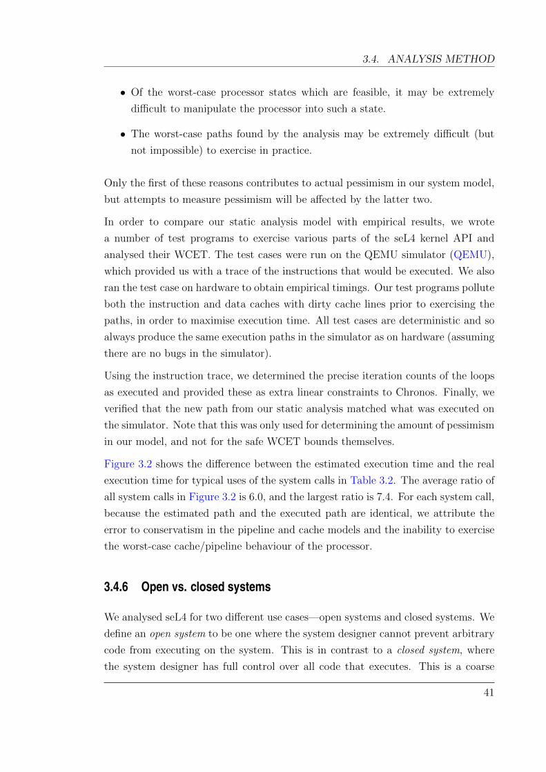
3.4. ANALYSIS METHOD
• Of the worst-case processor states which are feasible, it may be extremely
difficult to manipulate the processor into such a state.
• The worst-case paths found by the analysis may be extremely difficult (but
not impossible) to exercise in practice.
Only the first of these reasons contributes to actual pessimism in our system model,
but attempts to measure pessimism will be affected by the latter two.
In order to compare our static analysis model with empirical results, we wrote
a number of test programs to exercise various parts of the seL4 kernel API and
analysed their WCET. The test cases were run on the QEMU simulator (QEMU),
which provided us with a trace of the instructions that would be executed. We also
ran the test case on hardware to obtain empirical timings. Our test programs pollute
both the instruction and data caches with dirty cache lines prior to exercising the
paths, in order to maximise execution time. All test cases are deterministic and so
always produce the same execution paths in the simulator as on hardware (assuming
there are no bugs in the simulator).
Using the instruction trace, we determined the precise iteration counts of the loops
as executed and provided these as extra linear constraints to Chronos. Finally, we
verified that the new path from our static analysis matched what was executed on
the simulator. Note that this was only used for determining the amount of pessimism
in our model, and not for the safe WCET bounds themselves.
Figure 3.2 shows the difference between the estimated execution time and the real
execution time for typical uses of the system calls in Table 3.2. The average ratio of
all system calls in Figure 3.2 is 6.0, and the largest ratio is 7.4. For each system call,
because the estimated path and the executed path are identical, we attribute the
error to conservatism in the pipeline and cache models and the inability to exercise
the worst-case cache/pipeline behaviour of the processor.
3.4.6 Open vs. closed systems
We analysed seL4 for two different use cases—open systems and closed systems. We
define an open system to be one where the system designer cannot prevent arbitrary
code from executing on the system. This is in contrast to a closed system, where
the system designer has full control over all code that executes. This is a coarse
41
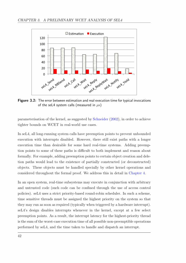
CHAPTER 3. A PRELIMINARY WCET ANALYSIS OF SEL4
0
20
40
60
80
100
120
seL4_Sen
d
seL4_NBSen
d
seL4_Call
seL4_Wa
it
seL4_Reply
seL4_ReplyWa
it
seL4_No;fy
seL4_Yield
Es;ma;on Execu;on
Figure 3.2: The error between estimation and real execution time for typical invocationsof the seL4 system calls (measured in µs)
parameterisation of the kernel, as suggested by Schneider (2002), in order to achieve
tighter bounds on WCET in real-world use cases.
In seL4, all long-running system calls have preemption points to prevent unbounded
execution with interrupts disabled. However, there still exist paths with a longer
execution time than desirable for some hard real-time systems. Adding preemp-
tion points to some of these paths is difficult to both implement and reason about
formally. For example, adding preemption points to certain object creation and dele-
tion paths would lead to the existence of partially constructed (or deconstructed)
objects. These objects must be handled specially by other kernel operations and
considered throughout the formal proof. We address this in detail in Chapter 4.
In an open system, real-time subsystems may execute in conjunction with arbitrary
and untrusted code (such code can be confined through the use of access control
policies). seL4 uses a strict priority-based round-robin scheduler. In such a scheme,
time sensitive threads must be assigned the highest priority on the system so that
they may run as soon as required (typically when triggered by a hardware interrupt).
seL4’s design disables interrupts whenever in the kernel, except at a few select
preemption points. As a result, the interrupt latency for the highest-priority thread
is the sum of the worst-case execution time of all possible non-preemptible operations
performed by seL4, and the time taken to handle and dispatch an interrupt.
42
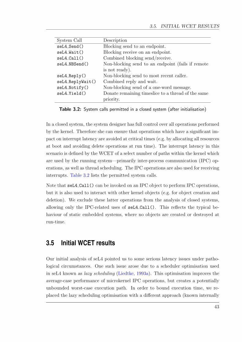
3.5. INITIAL WCET RESULTS
System Call DescriptionseL4 Send() Blocking send to an endpoint.seL4 Wait() Blocking receive on an endpoint.seL4 Call() Combined blocking send/receive.seL4 NBSend() Non-blocking send to an endpoint (fails if remote
is not ready).seL4 Reply() Non-blocking send to most recent caller.seL4 ReplyWait() Combined reply and wait.seL4 Notify() Non-blocking send of a one-word message.seL4 Yield() Donate remaining timeslice to a thread of the same
priority.
Table 3.2: System calls permitted in a closed system (after initialisation)
In a closed system, the system designer has full control over all operations performed
by the kernel. Therefore she can ensure that operations which have a significant im-
pact on interrupt latency are avoided at critical times (e.g. by allocating all resources
at boot and avoiding delete operations at run time). The interrupt latency in this
scenario is defined by the WCET of a select number of paths within the kernel which
are used by the running system—primarily inter-process communication (IPC) op-
erations, as well as thread scheduling. The IPC operations are also used for receiving
interrupts. Table 3.2 lists the permitted system calls.
Note that seL4 Call() can be invoked on an IPC object to perform IPC operations,
but it is also used to interact with other kernel objects (e.g. for object creation and
deletion). We exclude these latter operations from the analysis of closed systems,
allowing only the IPC-related uses of seL4 Call(). This reflects the typical be-
haviour of static embedded systems, where no objects are created or destroyed at
run-time.
3.5 Initial WCET results
Our initial analysis of seL4 pointed us to some serious latency issues under patho-
logical circumstances. One such issue arose due to a scheduler optimisation used
in seL4 known as lazy scheduling (Liedtke, 1993a). This optimisation improves the
average-case performance of microkernel IPC operations, but creates a potentially
unbounded worst-case execution path. In order to bound execution time, we re-
placed the lazy scheduling optimisation with a different approach (known internally
43
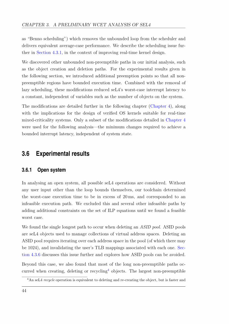
CHAPTER 3. A PRELIMINARY WCET ANALYSIS OF SEL4
as “Benno scheduling”) which removes the unbounded loop from the scheduler and
delivers equivalent average-case performance. We describe the scheduling issue fur-
ther in Section 4.3.1, in the context of improving real-time kernel design.
We discovered other unbounded non-preemptible paths in our initial analysis, such
as the object creation and deletion paths. For the experimental results given in
the following section, we introduced additional preemption points so that all non-
preemptible regions have bounded execution time. Combined with the removal of
lazy scheduling, these modifications reduced seL4’s worst-case interrupt latency to
a constant, independent of variables such as the number of objects on the system.
The modifications are detailed further in the following chapter (Chapter 4), along
with the implications for the design of verified OS kernels suitable for real-time
mixed-criticality systems. Only a subset of the modifications detailed in Chapter 4
were used for the following analysis—the minimum changes required to achieve a
bounded interrupt latency, independent of system state.
3.6 Experimental results
3.6.1 Open system
In analysing an open system, all possible seL4 operations are considered. Without
any user input other than the loop bounds themselves, our toolchain determined
the worst-case execution time to be in excess of 20 ms, and corresponded to an
infeasible execution path. We excluded this and several other infeasible paths by
adding additional constraints on the set of ILP equations until we found a feasible
worst case.
We found the single longest path to occur when deleting an ASID pool. ASID pools
are seL4 objects used to manage collections of virtual address spaces. Deleting an
ASID pool requires iterating over each address space in the pool (of which there may
be 1024), and invalidating the user’s TLB mappings associated with each one. Sec-
tion 4.3.6 discusses this issue further and explores how ASID pools can be avoided.
Beyond this case, we also found that most of the long non-preemptible paths oc-
curred when creating, deleting or recycling4 objects. The largest non-preemptible
4An seL4 recycle operation is equivalent to deleting and re-creating the object, but is faster and
44
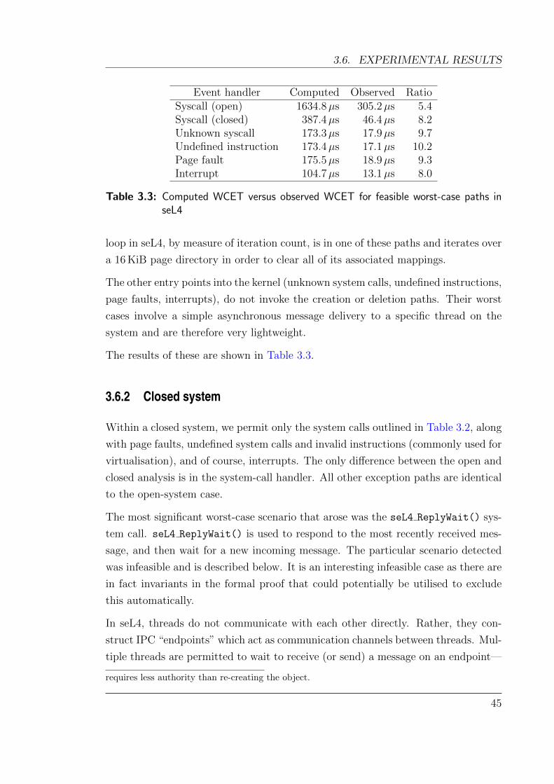
3.6. EXPERIMENTAL RESULTS
Event handler Computed Observed RatioSyscall (open) 1634.8µs 305.2µs 5.4Syscall (closed) 387.4µs 46.4µs 8.2Unknown syscall 173.3µs 17.9µs 9.7Undefined instruction 173.4µs 17.1µs 10.2Page fault 175.5µs 18.9µs 9.3Interrupt 104.7µs 13.1µs 8.0
Table 3.3: Computed WCET versus observed WCET for feasible worst-case paths inseL4
loop in seL4, by measure of iteration count, is in one of these paths and iterates over
a 16 KiB page directory in order to clear all of its associated mappings.
The other entry points into the kernel (unknown system calls, undefined instructions,
page faults, interrupts), do not invoke the creation or deletion paths. Their worst
cases involve a simple asynchronous message delivery to a specific thread on the
system and are therefore very lightweight.
The results of these are shown in Table 3.3.
3.6.2 Closed system
Within a closed system, we permit only the system calls outlined in Table 3.2, along
with page faults, undefined system calls and invalid instructions (commonly used for
virtualisation), and of course, interrupts. The only difference between the open and
closed analysis is in the system-call handler. All other exception paths are identical
to the open-system case.
The most significant worst-case scenario that arose was the seL4 ReplyWait() sys-
tem call. seL4 ReplyWait() is used to respond to the most recently received mes-
sage, and then wait for a new incoming message. The particular scenario detected
was infeasible and is described below. It is an interesting infeasible case as there are
in fact invariants in the formal proof that could potentially be utilised to exclude
this automatically.
In seL4, threads do not communicate with each other directly. Rather, they con-
struct IPC “endpoints” which act as communication channels between threads. Mul-
tiple threads are permitted to wait to receive (or send) a message on an endpoint—
requires less authority than re-creating the object.
45

CHAPTER 3. A PRELIMINARY WCET ANALYSIS OF SEL4
threads join a queue and are woken in turn as partners arrive. Deleting an endpoint
in such a state leads to a long-running operation as threads are unblocked and moved
back onto the scheduler’s run queue. Although this is done preemptibly, it still adds
a non-trivial amount of work to this path. On closed systems, we do not permit a
delete operation, so this scenario is not considered there.
However, seL4 Reply() and seL4 Wait() utilise a one-time endpoint (known as a
reply cap) which is stored in a dedicated location in each thread control block (the
reply slot). The kernel must delete the existing reply cap before a call to seL4 Wait()
and after a call to seL4 Reply().
The analysis detected that deleting this reply cap could lead to a longer execution
time as it entered the deletion path. Even though we excluded explicit delete op-
erations from our analysis, this implicit delete operation was exposed. However, it
is impossible to construct this scenario, as a reply cap can only be used by other
threads if it is first removed from the reply slot. Therefore the delete operation on
the reply slot never needs to enter the longer deletion path.
With this knowledge, we added an extra constraint which excluded this infeasible
path. The new analysis determined that the worst-case path for each kernel entry
point was bounded by the time taken to perform an IPC.
In a feasible IPC operation, we identified three factors which affected execution time.
The first is that endpoints are addressed using a structure resembling guarded page
tables (Liedtke, 1993b); decoding the address involves traversing up to 32 edges
of a directed graph. The second is, unsurprisingly, the size of the message to be
transferred, on which seL4 places a hard limit of 120 32-bit words. Finally, an
IPC may also grant the recipient access to seL4 objects, which requires additional
bookkeeping to be done by the kernel. With these three factors exercised to their
limits, the worst-case latency is still bounded to a reasonable value.
We reproduced this case on hardware and measured its execution time, as shown in
Table 3.3.
3.6.3 Analysis of results
The results in Table 3.3 show that there is a factor of up to 10.2 between the observed
and computed execution times. This disparity can be attributed to both the ran-
dom cache replacement policy of the instruction and data caches, and conservatism
46
3.6. EXPERIMENTAL RESULTS
in modeling the Cortex-A8 pipeline. It is extremely difficult to model worst-case
scenarios for these without very fine control over the processor’s state.
Part of this disparity is also because the worst-case paths identified by the analysis
are in fact infeasible. Although we manually excluded some infeasible paths, the
final paths detected may still contain smaller portions that cannot be executed in
practice. There is scope here to improve the bounds further, to the degree permitted
by the inherent unpredictability of the hardware.
To compute the worst-case interrupt latency of the system, from interrupt arrival to
a userspace interrupt handler executing, we take the largest WCET value from the
given scenario and add the WCET of delivering an interrupt to the highest priority
thread on the system.
Overall, these results show that seL4 could be used as a platform for closed systems
and provide a guaranteed interrupt response time of 387.4 + 104.7 = 492.1µs on
this hardware. In open systems, the interrupt response time is 1635µs + 104.7µs =
1.74 ms, which is still quite reasonable for many applications. However there is
clearly scope to improve the response times for both open and closed systems.
In this thesis, we focus primarily on the interrupt response time for high-priority
threads which are ready to execute in response to an interrupt. Based on the re-
sults we have obtained, it is possible to compute the worst-case execution time for
individual system calls—i.e. the time between a system call being issued and its
completion. Such an analysis must account for several factors: (1) the amount of
state affected by the operation (e.g. number of objects, size of memory regions, etc);
(2) all possible preemptions of higher priority operations and their execution times;
and (3) whether the amount of work for a preempted system call can be increased
while preempted. The first two factors are heavily dependent on the design of the
overall system, and seL4 alone cannot make any guarantees. However, seL4 is de-
signed to mitigate the third factor, ensuring that the amount of work required for an
operation cannot be increased after the operation begins. For example, cancelling
all pending messages on an endpoint will only cancel those messages which were
pending when the system call was issued (other access control mechanisms exist
to ensure that new messages cannot be enqueued, but these need not be utilised).
Similarly, when a deletion commences, it is possible to compute precisely how much
work is required to complete the operation, regardless of other system activities.
47

CHAPTER 3. A PRELIMINARY WCET ANALYSIS OF SEL4
BBs before BBs afterFunction inlining inlining Chronos CPLEX Total
1 arm swi syscall 2, 384 433, 085 6m52s 227m37s 234m29s2 handleSyscall 2, 381 433, 082 6m42s 226m9s 232m51s3 decodeInvocation 2, 148 139, 066 2m49s 44m11s 47m0s4 handleInvocation 2, 237 140, 890 2m20s 14m50s 17m10s5 decodeCNodeInvocation 985 32, 106 37s 4m59s 5m36s6 decodeTCBInvocation 958 100, 810 2m11s 2m14s 4m25s
Table 3.4: Most computationally intensive seL4 functions when solving for WCET,showing the analysis time spent by Chronos and the ILP solver
3.6.4 Computation time
To examine the scalability of our analysis method on seL4, we computed the worst-
case execution time for not only the top-level entry points, but also all subroutines
in the seL4 binary. Table 3.4 shows the functions in seL4 that took the longest time
to analyse. All results were obtained on an Intel Xeon running at 2.66 GHz with
10 GiB of memory.
arm swi syscall is the assembly-level entry point for all system calls. It directly
or indirectly calls the other functions listed in the table. All other functions within
the kernel are solved much faster (in minutes or seconds, rather than hours). The
table also shows the number of basic blocks (BBs) before and after virtual inlining,
as a measure of how complex the computation is.
Only five functions took more than five minutes to solve. They contain the largest
number of basic blocks of any function in the kernel, once virtual inlining has been
performed. From this table we can can see that, given a little patience, our approach
scales up to the size of seL4.
3.7 Summary
This chapter presented an interrupt-response-time analysis of the seL4 microkernel,
highlighting the properties of the code base that make it amenable to static analysis.
This is the first such published analysis of a protected operating system kernel
providing virtual memory. There are many properties of seL4 that both ease the
analysis process and reduce the interrupt latency, without the need for a fully-
preemptible kernel. Our analysis shows that seL4’s WCET can be kept low enough
48
3.7. SUMMARY
for many closed- as well as many open-system applications.
seL4 is designed as a highly-secure general-purpose OS kernel, suitable for a large
class of real-time, best-effort and hybrid systems. One of the design decisions sup-
porting these goals is to disallow interrupts in the kernel, and instead limit interrupt
latencies via specific preemption points. seL4’s latencies are currently over one mil-
lisecond in the worst case. With the introduction of additional preemption points,
and guided by this analysis, seL4’s interrupt latency can be reduced significantly.
The following chapter investigates how to achieve this without compromising on the
verifiability of the kernel.
There are still significant differences between the results of static analysis and mea-
surements on hardware. A part of this is due to conservatism in the pipeline and
cache model used by static analysis (mostly inevitable due to the degree of undocu-
mented behaviour in the processor). Another factor is code paths which are difficult
to reproduce from userspace because of very fragile pathological cases. It may be
possible to set up the state of the relevant data structures from within the kernel to
force these paths, but this may not result in a realistic scenario.
Finally, some amount of pessimism comes from undetected infeasible paths in the
control flow graph. While some of these paths could be eliminated manually in our
analysis, there is scope for automation which would remove both human effort and
the potential for human error. Since performing this analysis, we have automated
the determination of loop bounds (Chapter 6), and the detection of some of the
infeasible paths (Chapter 7).
Despite the limitations of the analysis, we have been able to analyse the complete
seL4 kernel. In conjunction with a formal proof of functional correctness, this already
makes seL4 a compelling platform for safety-critical applications.
Whilst the focus of this thesis has been WCET analysis for determining the interrupt
response time of the kernel, the results of our analysis can also be used to determine
bounds on the execution time of individual kernel operations. The bounds for non-
preemptible kernel operations are directly obtainable using the tools and analysis
presented, whilst bounds for preemptible operations need to consider the running
system and its possible preemptions. This knowledge forms part of a schedulability
analysis which is crucial for designing reliable hard real-time systems.
49

Chapter 4
Formal verification vs interrupt latency
This chapter is based on work published at EuroSys 2012 in which I was the primary author
(Blackham, Shi, and Heiser, 2012a). Many members of the seL4 team contributed to the ideas
presented in this chapter, including Kevin Elphinstone (lead seL4 architect), Adrian Danis,
Dhammika Elkaduwe, Gernot Heiser, Ben Leslie, Thomas Sewell and Gerwin Klein. However,
the final design and implementation of the modifications described are my own work. The
WCET analysis in this chapter was performed primarily by myself, with assistance from Yao
Shi. The correctness proofs of the seL4 scheduler changes were completed by Timothy Bourke
and the seL4 verification team.
4.1 Overview
The previous chapter presented a worst-case execution time analysis of seL4 which
required some modifications in order to ensure bounded interrupt latencies. We saw
that despite being bounded, the interrupt response time was still significantly large
for open systems (over 1 millisecond). Although we could avoid large interrupt
latencies through careful system construction (using the “closed system” model),
we would prefer to remove the sources of interrupt latency from the kernel itself.
Our aim is to be able to give shorter guarantees on seL4’s interrupt response time
without the need for artificial limitations.
Like most of its predecessor L4 kernels, seL4 disables interrupts throughout ker-
nel execution, except at specific preemption points. This was originally done to
optimise average-case performance, at the expense of increased average-case inter-
51

CHAPTER 4. FORMAL VERIFICATION VS INTERRUPT LATENCY
rupt latency. However, it was also essential to making the formal verification of
the functional behaviour of seL4 tractable. This suggests that constructing a kernel
which can guarantee acceptably short interrupt latencies, and be amenable to formal
verification, requires careful design.
In this chapter, we explore the limits of response time of a verified protected mi-
crokernel such as seL4, and the design implications for kernels for real-time mixed-
criticality systems. We describe the bottlenecks encountered in achieving suitable
real-time performance and the challenges associated with overcoming them, whilst
retaining the ability to be verified and thereby ensure strong functional guarantees.
We introduce the notion of incremental consistency as a design philosophy which
can ease the formal verification of real-time kernels and applications.
We have implemented changes to seL4 which reduce its interrupt latency by an
order of magnitude—from milliseconds to hundreds of microseconds. Although re-
verification of these changes is ongoing work, it is largely mechanical and similar
in nature to other proof maintenance activities over the past four years since the
original completion of the seL4 proof (Klein et al., 2009b).
The previous analysis of seL4’s response time in Chapter 3 targeted an 800 MHz
OMAP3 CPU. The work in this chapter uses a different platform, the i.MX31,
in order to benefit from better cache management. The OMAP3 differs from the
i.MX31 in CPU speed, micro-architecture and memory latency. We have repeated
our previous analysis on the i.MX31 platform to obtain directly comparable results.
4.2 Design considerations
4.2.1 Multi-threading models
In Section 3.3, we introduced the concepts of event-based and process-based ap-
proaches to support multi-threading in a kernel. These concepts are orthogonal but
related to the notion of fully-preemptible or non-preemptible kernels, as described
in Section 2.2.1. In this section, we address all combinations of the two and examine
the implications for formal verification and interrupt latency.
In the process-based model, each thread is allocated a dedicated kernel stack. This
kernel stack is used for handling requests on behalf of the thread. It implicitly stores
52

4.2. DESIGN CONSIDERATIONS
the state of any kernel operation in progress within the contents of the call stack and
local variables stored on the stack. A context switch alters the stack pointer and
thereby modifies the entire calling context. This poses challenges for both formal
verification and static analysis—in both domains, many techniques are dependent
on the notion of a “calling context” of a function, which implicitly encodes part of
its execution history. The context switch in a process-based kernel stymies the use
of any techniques that depend on the calling context.
A process-based kernel lends itself to being made fully preemptible (Ford et al.,
1999). With some defensive coding, an interrupt can be permitted almost anywhere
in the kernel. Therefore a fully-preemptible process-based kernel allows for very
short interrupt response times, despite significantly complicating WCET analysis.
The process-based kernel was also originally thought to be more efficient in the
presence of frequent context switching (Liedtke, 1993a). However, results on modern
ARM hardware have shown the difference to be negligible and in fact event-based
kernels have been shown to perform better in macro benchmarks (Warton, 2005).
An event-based kernel uses a single kernel stack to handle requests for all threads on
the system. This reduces memory consumption significantly, but changes the way
in which preemption can be handled. As the stack implicitly encodes an ordering
on function returns, it cannot be shared amongst multiple threads as doing so could
result in deadlock due to stack blocking. Scheduling disciplines such as the stack
resource policy (Baker, 1991) are able to overcome this, however they enforce specific
scheduling requirements, limiting system flexibility.
Some event-based kernels such as QNX Neutrino (QNX) are made fully preemptible
by discarding the shared stack on preemption. The preempted operation is later
restarted from the kernel’s entry point. However, under high interrupt rates, such a
model cannot guarantee forward progress of a preempted thread, as the preemption
may occur before any progress is made.
In fully-preemptible kernels, under both the process-based and event-based models,
the control flow can be diverted at any point by an incoming interrupt. This is a
significant challenge for formal verification and also static analysis (particularly for
static WCET analysis).
L4 kernels have traditionally been process-based but not fully preemptible.1 In a
1 There are some exceptions: the L4-based Fiasco kernel (Hohmuth, 2002) is process-based andalso preemptible; both OKL4 (Heiser and Leslie, 2010) and seL4 use a single kernel stack and are
53

CHAPTER 4. FORMAL VERIFICATION VS INTERRUPT LATENCY
microkernel-based system, kernel execution tends to be dominated by fast inter-
process communication (IPC) operations; there is little benefit in making the mi-
crokernel fully-preemptible, as long as the worst-case latencies of the longer-running
operations are kept reasonable through well-placed preemption points.
The design used by seL4 is non-preemptible and event-based, and thereby provides
reasonable average-case performance and guarantees forward progress under high
interrupt rates. It also simplifies formal verification and static analysis, as the seL4
code has a standard procedural control flow like any regular C program.
4.2.2 Saving preempted state
In seL4’s non-preemptible event-based model, preemption points are manually in-
serted to detect and handle pending interrupts in long operations. If an interrupt
is found to be pending, the state of the current operation must be explicitly saved.
There are several ways in which this state can be saved (and the operation later
resumed).
One possibility is to use continuations to efficiently represent the saved state of
a blocking or preempted kernel operation (Draves et al., 1991). A continuation
specifies (a) the function that a thread should execute when it next runs; and (b) a
structure containing any necessary saved state. Using continuations allows a thread
to discard its stack whilst it is blocked or preempted.
An alternative is to treat a preempted operation effectively as a restartable system
call. In this case, when a preemption point detects an interrupt, any necessary
state for the preempted operation is saved as the kernel returns up the call stack.
The thread is left in a state where simply re-executing the original system call will
continue the operation.
seL4 uses the restartable system call model over continuations. It uses a common
entry point for both new and restarted kernel operations, which means that the
code to validate an operation can be shared between both cases. For example, both
a new and a resumed deletion operation must check if the object to be deleting
(still) exists. This reduces code duplication and also verification effort, as kernel re-
entry automatically re-establishes the required invariants. It also simplifies reasoning
about the kernel’s correctness: it is not necessary to reason about what state a
not fully preemptible.
54
4.2. DESIGN CONSIDERATIONS
preempted thread is in and whether it was performing an operation. Instead, it
suffices to only reason about the state of objects in the system.
This design leads to a small amount of duplicated run-time effort, as the system call
must be decoded again each time a preempted operation is resumed. However, the
code paths taken are likely to be hot in the CPU’s caches. Work on the Fluke kernel
demonstrated that these overheads are negligible (Ford et al., 1999).
4.2.3 Incremental consistency
A noteworthy design pattern in seL4 is an idea we call incremental consistency:
large composite objects are composed of individual components that can be added,
deleted, or updated one-at-a-time. Specifically, there is always a constant-time
operation that will partially construct, deconstruct, or modify a large composite
object and still maintain a coherent system. In seL4, this is relevant to objects
such as address spaces and book-keeping data structures, which commonly pose
significant issues in deletion paths.
Incrementally consistent designs have several benefits:
1. they provide invariants which are almost certainly required for verification;
2. they reduce the verification burden as such invariants are only violated for
brief periods before being reestablished;
3. they provide natural locations for inserting preemption points, helping to re-
duce the interrupt latency of real-time systems.
Although a simple concept, it is not always easy to maintain in a system with
complex data structures and intricate dependencies between them.
4.2.4 Proof invariants of seL4
In seL4, consistency of the kernel is defined by a set of formalised invariants on
the kernel’s state and in turn all objects in the kernel. There are in fact hundreds
of invariants and lemmas that are maintained across all seL4 operations. These
include:
55

CHAPTER 4. FORMAL VERIFICATION VS INTERRUPT LATENCY
• well-formed data structures: structures such as linked lists are well-formed—
i.e. there are no circular links and all back-pointers point to the correct node
in doubly-linked lists;
• object alignment: all objects in seL4 are aligned to their size, and do not
overlap in memory with any other objects;
• algorithmic invariants: some optimisations in seL4 depend on specific proper-
ties being true, allowing redundant checks to be eliminated;
• book-keeping invariants: seL4 maintains a complex data-structure that stores
information about what objects exist on the system and who has access to
them. The integrity of seL4 depends on the consistency of this information.
The formally-verified seL4 code base proves that all kernel operations will maintain
all of the given invariants. Any modifications to seL4 require proving that these in-
variants still hold, in addition to proving that the code still correctly implements the
specification of the kernel. Therefore, for each preemption point that we add to seL4,
we must correspondingly update the proof in order to maintain these invariants.
In some cases, it is not possible to maintain all invariants, in which case the invariant
may be replaced by a weaker statement. The weakened invariant must be sufficient
to satisfy the remainder of the proof over the whole kernel. If an aspect of the
proof fails with the weakened invariant, this generally suggests that a bug has been
introduced and that extra safety checks may be required in the code.
4.3 Areas of improvement
In this section, we look at some of the long-running operations in seL4 and examine
how to either add suitable preemption points or replace the operations with better
algorithms. Most of these operations, whilst presented in the context of seL4, are
typical of any OS kernel providing abstractions such as protected address spaces,
threads and IPC.
There are some operations that may be found in other OS kernels which are not
present in seL4. One example is the absence of any memory allocation routines.
Almost all allocation policies are delegated to userspace; seL4 provides only the
56

4.3. AREAS OF IMPROVEMENT
mechanisms required to enforce policies and ensure they are safe (e.g. checking that
objects do not overlap) (Elkaduwe et al., 2007). This design decision removes much
of the complexity of a typical allocator from seL4 as well as some potentially long-
running operations.
4.3.1 Removal of lazy scheduling
As mentioned in Section 3.5, our initial WCET analysis identified a problematic
optimisation in seL4 known as lazy scheduling. Lazy scheduling attempts to min-
imise the manipulation of scheduling queues on the critical path of IPC operations
(Liedtke, 1993a), and has traditionally been used in almost all L4 kernels (Fiasco is
an exception). It is based on the observation that in L4’s synchronous IPC model,
threads frequently block while sending a message to another thread, but in many
cases the other thread replies quickly. Multiple such ping-pongs can happen on a
single time slice, leading to repeated de-queueing and re-queueing of the same thread
in the scheduler’s run queue.
Lazy scheduling leaves a thread in the run queue when it executes a blocking IPC
operation. When the scheduler is next invoked, it dequeues all threads which are
still blocked. Pseudo-code for a scheduler implementing lazy scheduling is shown in
Figure 4.1.
Lazy scheduling can lead to pathological cases where the scheduler must dequeue a
large number of blocked threads (theoretically only limited by the amount of memory
available for thread control blocks), which leads to unbounded worst-case latency.
As the scheduler is responsible for determining which thread to run next, it is not
always feasible or even meaningful to add a preemption point to this potentially
long-running operation.
We therefore had to change the scheduling model so that only runnable threads
existed on the run queue. In order to maintain the benefits of lazy scheduling, we
use a different scheduling trick, (internally known as “Benno scheduling”, after the
engineer who first implemented it in an earlier version of L4): when a thread is
unblocked by an IPC operation and, according to its priority, it is able to execute
immediately, we switch directly to it and do not place it into the run queue (as it
may block again very soon). In particular, the currently running thread does not
need to be on the run queue. This has the same best-case performance as lazy
57

CHAPTER 4. FORMAL VERIFICATION VS INTERRUPT LATENCY
thread_t chooseThread ()
foreach (prio in priorities)
foreach (thread in runQueue[prio])
if (isRunnable(thread ))
return thread;
else
schedDequeue(thread );
return idleThread;
Figure 4.1: Pseudo-code of scheduler implementing lazy scheduling
thread_t chooseThread ()
foreach (prio in priorities)
thread = runQueue[prio].head;
if (thread != NULL)
return thread;
return idleThread;
Figure 4.2: Pseudo-code of scheduler without lazy scheduling
58

4.3. AREAS OF IMPROVEMENT
scheduling, but maintains good worst-case performance, as only a single thread (the
presently running one) may have to be enqueued lazily.
In this model the implementation of the scheduler is simplified, as it now just chooses
the first thread of highest priority, as demonstrated in the pseudo-code listing in
Figure 4.2. There is an existing invariant in the kernel that all runnable threads
on the system are either on the run queue or currently executing. This is sufficient
for lazy scheduling, but Benno scheduling obviously requires an additional invariant
which must be maintained throughout the kernel: that all threads on the scheduler’s
run queue must be in the runnable state.
This seemingly simple C code change impacts the proof in all functions that alter a
thread’s state, or modifies the scheduler’s run queue. The invariant must be proven
true when any thread ceases to be runnable and when any thread is placed onto the
run queue. The removal of lazy scheduling has since been implemented and proven
correct in the formally-verified kernel with these updated invariants.
4.3.2 Scheduler bitmaps
We added one more optimisation to the scheduler: a bitmap representing the pri-
orities that contain runnable threads. We make use of ARM’s count leading zeroes
(CLZ) instruction which finds the highest set bit in a 32-bit word, and executes in
a single cycle. seL4 supports 256 thread priorities, which we represent using a two-
level bitmap. The 256 priorities are divided into 8 “buckets” of 32 priorities each.
The top-level bitmap contains 8 bits each representing the existence of runnable
threads in any of the 32 priorities within a bucket. Each bucket has a 32-bit word
with each bit representing one of the 32 priorities. Using two loads and two CLZ
instructions, we can find the highest runnable priority very efficiently, and have thus
removed the loop from Figure 4.2 altogether.
This optimisation technique is commonly used in other OS schedulers and has re-
duced the WCET of seL4 in several cases. However, it introduces yet another
invariant to be proven: that the scheduler’s bitmap precisely reflects the state of
the run queues. As this is an incremental change to the existing scheduler, the
re-verification effort is significantly lowered.
59
CHAPTER 4. FORMAL VERIFICATION VS INTERRUPT LATENCY
4.3.3 Aborting IPC operations
Threads in seL4 do not communicate directly with each other; they instead commu-
nicate via endpoints which act as communication channels between threads. Multiple
threads may send or receive messages through an endpoint. Each endpoint main-
tains a linked list of all threads waiting to send or receive a message. Naturally,
this list can grow to an arbitrary length (limited by the number of threads in the
system, which is limited by the amount of physical memory that can be used for
threads, which in turn is theoretically limited by the size of free physical memory
after the kernel boots). The length of this list is not an issue for most operations,
as they can manipulate the list in constant time.
The only exception is the operation to delete an endpoint. Deletion must iterate over
and dequeue a potentially large number of threads. There is an obvious preemption
point in this operation: after each thread is dequeued. This intermediate step is
fortunately consistent with all existing invariants, even if the thread performing the
deletion operation is itself deleted. Forward progress is ensured by deactivating
the endpoint at the beginning of delete operations, so threads (including those just
dequeued) cannot attempt another IPC operation on the same endpoint.
The preemption point here is obvious because it is a direct result of the incremental
consistency design pattern in seL4. As a result, the impact of these changes on the
proof are minimal.
4.3.4 Aborting badged IPC operations
A related real-time challenge in seL4 is the aborting of badged IPC operations.
Badges are unforgeable tokens (represented as an integer) that server processes may
assign to clients. When a client sends a message to the server using a badge, the
server can be assured of the authenticity of the client. A server may revoke a specific
badge, so that it can ensure that no existing clients have access to that badge. Once
revoked, the server may re-issue the badge to a different client, preserving guarantees
of authenticity.
In order to revoke a badge, seL4 must first prevent any thread from starting a new
IPC operation using the badge, and second ensure that any pending IPC operations
using the badge are aborted. This second operation stores book-keeping informa-
tion in a multiset data structure, to track threads and their badges, and requires a
60
4.3. AREAS OF IMPROVEMENT
compromise between execution time, memory consumption and ease of verification.
The choice of data structure used has a significant impact on all three factors.
For example, a balanced binary-tree structure has very good worst-case and average-
case execution time, but requires more work in the verification effort; the invariants
involved in self-balancing binary tree structures are more tedious than linear data
structures. A hash-table-based data structure may be easier to verify, and has good
average-case performance, but raises challenging memory allocation issues in seL4,
where memory allocation is handled outside the kernel. It also does not improve
worst-case execution time, as a determined adversary could potentially force hash
collisions.
Instead, seL4 uses a simple linked list containing the list of waiting threads and their
associated badges, as described in Section 4.3.3. Enqueuing and dequeuing threads
are simple O(1) operations. In order to remove all entries with a specific badge,
seL4 must iterate over the list; this is a potentially unbounded operation, and so
we require a preemption point. Unlike the simple deletion case where we simply
restart from the beginning of the list, here we additionally need to store four pieces
of information:
1. at what point within the list the operation was preempted, so that we can
avoid repeating work and ensure forward progress;
2. a pointer to the last item in the list when the operation commenced, so that
new waiting clients do not affect the execution time of the original operation;
3. the badge which is currently being removed from the list, so that if a badge
removal operation is preempted and a second operation is started, the first
operation can be completed before starting the new one;
4. a pointer to the thread that was performing the badge removal operation when
preempted, so that if another thread needs to continue its operation, it can
indicate to the original thread that its operation has been completed.
With all this information, we are able to achieve our goal of incremental consis-
tency. The above information is associated with the endpoint object rather than
the preempted thread (as would be done in a continuation). In doing so, we can
reason simply about the state of objects in our invariants, rather than the state of
any preempted thread.
61
CHAPTER 4. FORMAL VERIFICATION VS INTERRUPT LATENCY
Note that although the preemption point bounds interrupt latency, this approach
gives a longer than desirable execution time for the badged abort operation, as every
waiting thread must be iterated over, rather than only threads waiting for a specific
badge. This has not yet been an issue in real systems, however, should it cause
problems then we may replace it with an alternative such as a self-balancing binary
tree data structure and undertake the extra verification effort required.
4.3.5 Object creation
When objects, such as threads, page tables or memory frames, are created on be-
half of the user, their contents must be cleared and/or initialised in order to avoid
information leakage. Clearing an object may be a long-running operation, as some
kernel objects are megabytes in size (e.g. large memory frames on ARM can be up
to 16 MiB in size; capability tables, used for managing authority, can be of arbitrary
size).
The code to clear an object was previously deep inside the object creation path,
and replicated for each type of object. Additionally, the code updated some of the
kernel’s state before objects were cleared, and the rest of the kernel’s state after
objects were cleared. Adding a preemption point in the middle of clearing an object
would therefore leave the kernel in an inconsistent state.
To make clearing of objects preemptible, seL4 required significant restructuring of
the object creation paths. We chose to clear out the contents of all objects prior to
any other kernel state being modified. The progress of this clearing is stored within
the object itself. The remainder of the creation code that manipulates the state of
the kernel (e.g. updating the kernel’s book-keeping data structures) can usually be
performed in one short, atomic pass.
Page directories (top-level page tables) however pose an added complication. The
top 256 MiB of virtual address space is reserved for the seL4 kernel, and is mapped
into all address spaces. When a new page directory is created, the kernel mappings
for this region must be copied in. This copy operation is embedded deep within the
creation path of page directories. There is also an seL4 invariant specifying that
all page directories will contain these global mappings—an invariant that must be
maintained upon exiting the kernel.
Preempting the global-mapping copy poses significant (though not insurmountable)
62
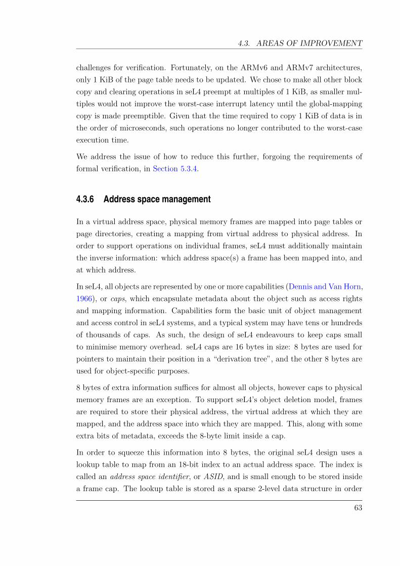
4.3. AREAS OF IMPROVEMENT
challenges for verification. Fortunately, on the ARMv6 and ARMv7 architectures,
only 1 KiB of the page table needs to be updated. We chose to make all other block
copy and clearing operations in seL4 preempt at multiples of 1 KiB, as smaller mul-
tiples would not improve the worst-case interrupt latency until the global-mapping
copy is made preemptible. Given that the time required to copy 1 KiB of data is in
the order of microseconds, such operations no longer contributed to the worst-case
execution time.
We address the issue of how to reduce this further, forgoing the requirements of
formal verification, in Section 5.3.4.
4.3.6 Address space management
In a virtual address space, physical memory frames are mapped into page tables or
page directories, creating a mapping from virtual address to physical address. In
order to support operations on individual frames, seL4 must additionally maintain
the inverse information: which address space(s) a frame has been mapped into, and
at which address.
In seL4, all objects are represented by one or more capabilities (Dennis and Van Horn,
1966), or caps, which encapsulate metadata about the object such as access rights
and mapping information. Capabilities form the basic unit of object management
and access control in seL4 systems, and a typical system may have tens or hundreds
of thousands of caps. As such, the design of seL4 endeavours to keep caps small
to minimise memory overhead. seL4 caps are 16 bytes in size: 8 bytes are used for
pointers to maintain their position in a “derivation tree”, and the other 8 bytes are
used for object-specific purposes.
8 bytes of extra information suffices for almost all objects, however caps to physical
memory frames are an exception. To support seL4’s object deletion model, frames
are required to store their physical address, the virtual address at which they are
mapped, and the address space into which they are mapped. This, along with some
extra bits of metadata, exceeds the 8-byte limit inside a cap.
In order to squeeze this information into 8 bytes, the original seL4 design uses a
lookup table to map from an 18-bit index to an actual address space. The index is
called an address space identifier, or ASID, and is small enough to be stored inside
a frame cap. The lookup table is stored as a sparse 2-level data structure in order
63

CHAPTER 4. FORMAL VERIFICATION VS INTERRUPT LATENCY
Page table
Frame cap Frame
Page directory
ASID directory
ASID pool
Figure 4.3: Virtual address spaces managed using ASIDs. Each arrow denotes a refer-ence (pointer) stored in one object, referring to another object.
to minimise space usage—the first 8 bits of the ASID are an index into the first
level (the ASID directory), and the remaining 10 bits are an index into the second
level (an ASID pool). Each ASID pool provides entries for 1024 address spaces. The
objects and references required for using ASIDs are shown in Figure 4.3.
Using ASIDs offered the additional benefit of enabling dangling references to deleted
address spaces to safely exist. If frame caps were to store a reference to the address
space itself, then when the address space is deleted, all frame caps referring to it
would need to be updated to purge this reference. By instead indirecting through
the ASID table, the references from each frame cap, whilst stale, are harmless. Any
time the ASID stored in a frame cap is used, it can be simply checked that the
mapping in the address space (if any still exist) agrees with the frame cap. As a
result, deleting an address space in this design simply involves: (a) removing one
entry from the ASID lookup table, and (b) invalidating any TLB entries from the
address space.
However, the use of ASIDs poses issues for interrupt latency in other areas, such
as locating a free ASID to allocate, and deleting an ASID pool. Locating a free
ASID is difficult to make preemptible—in the common case, a free ASID would be
found immediately, but a pathological case may require searching over 1024 possible
64
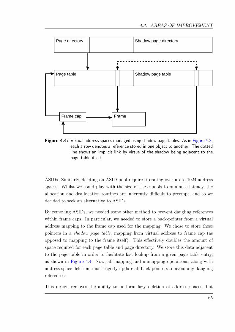
4.3. AREAS OF IMPROVEMENT
Shadow page directory
Page table Shadow page table
FrameFrame cap
Page directory
Figure 4.4: Virtual address spaces managed using shadow page tables. As in Figure 4.3,each arrow denotes a reference stored in one object to another. The dottedline shows an implicit link by virtue of the shadow being adjacent to thepage table itself.
ASIDs. Similarly, deleting an ASID pool requires iterating over up to 1024 address
spaces. Whilst we could play with the size of these pools to minimise latency, the
allocation and deallocation routines are inherently difficult to preempt, and so we
decided to seek an alternative to ASIDs.
By removing ASIDs, we needed some other method to prevent dangling references
within frame caps. In particular, we needed to store a back-pointer from a virtual
address mapping to the frame cap used for the mapping. We chose to store these
pointers in a shadow page table, mapping from virtual address to frame cap (as
opposed to mapping to the frame itself). This effectively doubles the amount of
space required for each page table and page directory. We store this data adjacent
to the page table in order to facilitate fast lookup from a given page table entry,
as shown in Figure 4.4. Now, all mapping and unmapping operations, along with
address space deletion, must eagerly update all back-pointers to avoid any dangling
references.
This design removes the ability to perform lazy deletion of address spaces, but
65

CHAPTER 4. FORMAL VERIFICATION VS INTERRUPT LATENCY
resolves many of the latency issues surrounding the management of ASID pools. We
needed to insert preemption points in the code to delete address spaces, however this
is trivial to do and can be done without violating any invariants on the kernel’s state.
The natural preemption point in the deletion path is to preempt after unmapping
each entry in a page table or page directory. To avoid repeating unnecessary work,
we also store the index of the lowest mapped entry in the page table and only resume
the operation from that point.
We observe that the ability to add a preemption point here is again a direct result
of the shadow page table design adhering to the incremental consistency design
pattern.
Memory Overhead of Shadow Page Tables The space overhead of shadow page tables
might be considered detrimental on some systems. We can compare it to an alter-
native solution, where we utilise a frame table to maintain bookkeeping information
about every physical page on the system. This is the approach used by many other
operating systems, including Linux.
The frame table incurs a fixed memory overhead and removes the need for shadows.
In its simplest form, without support for sharing pages between address spaces
(which the shadow page table solution does support), a frame table would require
a single pointer to track each frame cap created. On a 32-bit system with 256 MiB
of physical memory and 4 KiB frames, the frame table would occupy 256 KiB of
memory. On ARMv6 platforms, page directories are 16 KiB and page tables are
1 KiB (each page table spans 1 MiB of virtual address space). A densely-packed
page directory covering 256 MiB of virtual address space would use an extra 256 KiB
in shadow page tables, and an extra 16 KiB per address space in page directories.
In this scenario, the difference between the two approaches is negligible (16 KiB).
Shadow page tables have higher memory overheads when address spaces are sparsely-
populated. However, even without shadow page tables, sparsely-populated address
already incur wasted space in the page table structures. The use of shadow page
tables only amplifies (doubles) this wastage.
66
4.4. L1 CACHE PINNING
4.4 L1 cache pinning
In order to achieve faster interrupt delivery and tighter bounds on the worst-case
execution time (WCET) of seL4, we modified seL4 to pin specific cache lines into
the L1 caches so that these cache lines would not be evicted. We selected the
interrupt delivery path, along with some commonly accessed memory regions to be
permanently pinned into the instruction and data caches. The specific lines to pin
were chosen based on execution traces of both a typical interrupt delivery, and some
worst-case interrupt delivery paths.
As the cache on our target platform (described in Section 4.5.1) supports locking
one or more complete cache ways, we can choose to lock 1/4, 1/2 or 3/4 of the contents
of the cache. We selected as much as would fit into 1/4 of the cache (4 KiB), without
resorting to code placement optimisations. A total of 118 instruction cache lines
were pinned, along with the first 256 bytes of stack memory and some key data
regions.
The benefit of cache pinning on worst-case execution time is shown in Table 4.1. On
the interrupt path, where the pinned cache lines have the greatest benefit, the worst-
case execution time is almost halved. On other paths, the gain is less significant but
still beneficial.
Of course, these benefits do not come for free; as a portion of the cache has been
partitioned for specific code paths, the remainder of the system has less cache for
general usage which can adversely affect average-case performance if not carefully
managed. A system with hard real-time requirements may also require that code
and data used for deadline-critical tasks are pinned into the cache. Methods to
optimally select cache lines to pin for periodic hard real-time task sets have been
the subject of previous research (Campoy et al., 2001; Puaut and Decotigny, 2002).
Our platform has a 128 KiB unified L2 cache with a hit access latency of 26 cycles
(compared with external memory latency of 96 cycles). Our compiled seL4 binary
is 36 KiB, and so it would be possible to lock the entire seL4 microkernel into the
L2 cache. Doing so would drastically reduce execution time even further, but our
analysis tools did not yet provide such support when this analysis was performed.
In Chapter 5, our newer analysis tools allow us to add this support and reduce the
worst-case latency even further as a result.
67
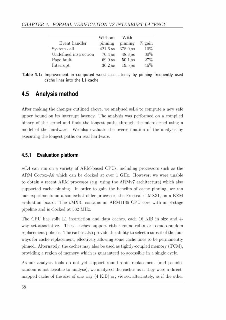
CHAPTER 4. FORMAL VERIFICATION VS INTERRUPT LATENCY
Without WithEvent handler pinning pinning % gain
System call 421.6µs 378.0µs 10%Undefined instruction 70.4µs 48.8µs 30%Page fault 69.0µs 50.1µs 27%Interrupt 36.2µs 19.5µs 46%
Table 4.1: Improvement in computed worst-case latency by pinning frequently usedcache lines into the L1 cache
4.5 Analysis method
After making the changes outlined above, we analysed seL4 to compute a new safe
upper bound on its interrupt latency. The analysis was performed on a compiled
binary of the kernel and finds the longest paths through the microkernel using a
model of the hardware. We also evaluate the overestimation of the analysis by
executing the longest paths on real hardware.
4.5.1 Evaluation platform
seL4 can run on a variety of ARM-based CPUs, including processors such as the
ARM Cortex-A8 which can be clocked at over 1 GHz. However, we were unable
to obtain a recent ARM processor (e.g. using the ARMv7 architecture) which also
supported cache pinning. In order to gain the benefits of cache pinning, we ran
our experiments on a somewhat older processor, the Freescale i.MX31, on a KZM
evaluation board. The i.MX31 contains an ARM1136 CPU core with an 8-stage
pipeline and is clocked at 532 MHz.
The CPU has split L1 instruction and data caches, each 16 KiB in size and 4-
way set-associative. These caches support either round-robin or pseudo-random
replacement policies. The caches also provide the ability to select a subset of the four
ways for cache replacement, effectively allowing some cache lines to be permanently
pinned. Alternately, the caches may also be used as tightly-coupled memory (TCM),
providing a region of memory which is guaranteed to accessible in a single cycle.
As our analysis tools do not yet support round-robin replacement (and pseudo-
random is not feasible to analyse), we analysed the caches as if they were a direct-
mapped cache of the size of one way (4 KiB) or, viewed alternately, as if the other
68

4.5. ANALYSIS METHOD
three cache ways were pinned with user data. This is a pessimistic but sound
approximation of the cache’s behaviour, as only the most recently accessed cache
line in any cache set is guaranteed to reside in the cache when next accessed.
The i.MX31 also provides a unified 128 KiB L2 cache which is 8-way set-associative.
The KZM board provides 128 MiB of RAM with an access latency of 60 cycles when
the L2 cache is disabled, or 96 cycles when the L2 cache is enabled. Due to this
significant disparity in memory latency, we analysed the kernel both with the L2
cache enabled and with it disabled.
We disabled the branch predictors of the ARM1136 CPU both on hardware used for
measurements and in the static analysis itself, as our analysis tools do not yet model
them. Interestingly, using the branch predictor increases the worst-case latency of
a branch: with branch predictors enabled, branches on the ARM1136 vary between
0 and 7 cycles, depending on the type of branch and whether or not it is predicted
correctly. With the branch predictor disabled, all branches execute in a constant 5
cycles.
The effect of disabling these features on execution time is quantified in Section 4.6.4.
4.5.2 Static analysis for worst-case execution time
Our analysis to compute the interrupt response time of seL4 is based upon work
described in Chapter 3. This section summarises the method used for this analysis
and highlights improvements over the previous analysis technique.
We use a newer version of Chronos (4.2), which provides support for a combined
L1 and L2 cache analysis (Chattopadhyay and Roychoudhury, 2009). As before, we
use Chronos to compute the worst-case execution time of seL4 and evaluate our im-
provements to seL4. We had previously modified Chronos to analyse binaries on the
ARMv7 architecture using a model of the Cortex-A8 pipeline. For this analysis we
adapted the pipeline model to support the ARM1136 CPU on our target hardware.
ARM’s documentation of the ARM1136 describes the performance characteristics
of the pipeline in detail (ARM, 2005).
Additional constraints were added manually in order to exclude certain infeasible
paths. As the analysis only considers the control flow graph, it has no insight into
the values of variables in the kernel. Therefore, it may consider paths that are
not actually realisable. In order to exclude these paths, we manually added extra
69

CHAPTER 4. FORMAL VERIFICATION VS INTERRUPT LATENCY
constraints to the ILP problem where necessary. These constraints take one of three
forms:
• a conflicts with b in f : specifies that the basic blocks at addresses a and b
are mutually exclusive, and will not both execute during an invocation of the
function f . If f is invoked multiple times, a and b can each be executed under
different invocations.
• a is consistent with b in f : specifies that the basic blocks at addresses a and
b will execute the same number of times during an invocation of the function
f .
• a executes n times: specifies that the basic block at address a will only ever
execute at most n times in total in all possible contexts.
It would be possible to transform these extra constraints into proof obligations—
statements which a verification engineer could be asked to prove formally. This
would remove the possibility of human error mistakenly excluding a path which
is in fact feasible, resulting in an unsound analysis. We validate some of these
constraints automatically in Chapter 6.
4.5.3 Comparing analysis with measurements
As in Section 3.4.5, we aim to gain some insight into how close our upper bounds are.
We wrote test programs to exercise the longest paths we could find ourselves (guided
by the results of the analysis) and ran these on the hardware. We measured the
execution time of these paths using the cycle counters available on the ARM1136’s
performance monitoring unit.
In order to quantify the amount of pessimism introduced by conservatism in the
hardware model, we use our static analysis model to compute the execution time of
paths that we are able to reproduce, and compared them with real hardware. The
results of this are shown in Figure 4.7. These are upper bounds on the amount of
pessimism, as we cannot guarantee that we have truly hit the worst-case scenario
for the hardware.
70
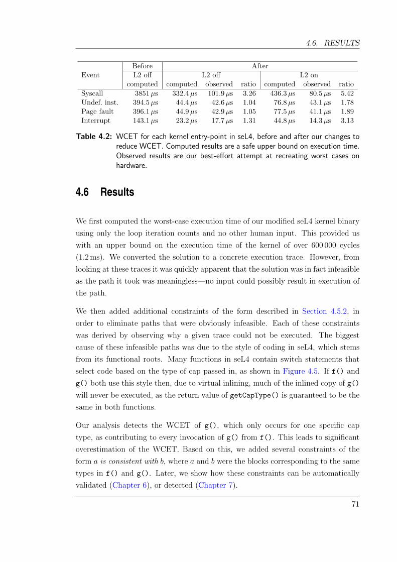
4.6. RESULTS
EventBefore AfterL2 off L2 off L2 on
computed computed observed ratio computed observed ratio
Syscall 3851µs 332.4µs 101.9µs 3.26 436.3µs 80.5µs 5.42Undef. inst. 394.5µs 44.4µs 42.6µs 1.04 76.8µs 43.1µs 1.78Page fault 396.1µs 44.9µs 42.9µs 1.05 77.5µs 41.1µs 1.89Interrupt 143.1µs 23.2µs 17.7µs 1.31 44.8µs 14.3µs 3.13
Table 4.2: WCET for each kernel entry-point in seL4, before and after our changes toreduce WCET. Computed results are a safe upper bound on execution time.Observed results are our best-effort attempt at recreating worst cases onhardware.
4.6 Results
We first computed the worst-case execution time of our modified seL4 kernel binary
using only the loop iteration counts and no other human input. This provided us
with an upper bound on the execution time of the kernel of over 600 000 cycles
(1.2 ms). We converted the solution to a concrete execution trace. However, from
looking at these traces it was quickly apparent that the solution was in fact infeasible
as the path it took was meaningless—no input could possibly result in execution of
the path.
We then added additional constraints of the form described in Section 4.5.2, in
order to eliminate paths that were obviously infeasible. Each of these constraints
was derived by observing why a given trace could not be executed. The biggest
cause of these infeasible paths was due to the style of coding in seL4, which stems
from its functional roots. Many functions in seL4 contain switch statements that
select code based on the type of cap passed in, as shown in Figure 4.5. If f() and
g() both use this style then, due to virtual inlining, much of the inlined copy of g()
will never be executed, as the return value of getCapType() is guaranteed to be the
same in both functions.
Our analysis detects the WCET of g(), which only occurs for one specific cap
type, as contributing to every invocation of g() from f(). This leads to significant
overestimation of the WCET. Based on this, we added several constraints of the
form a is consistent with b, where a and b were the blocks corresponding to the same
types in f() and g(). Later, we show how these constraints can be automatically
validated (Chapter 6), or detected (Chapter 7).
71
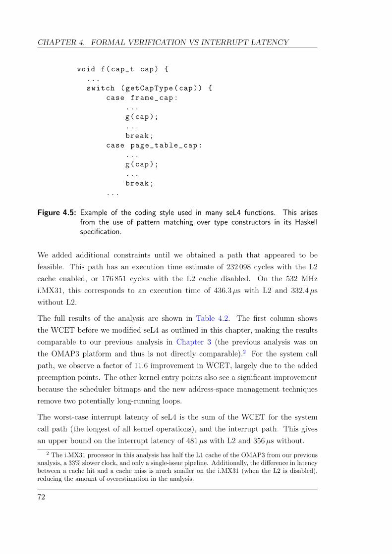
CHAPTER 4. FORMAL VERIFICATION VS INTERRUPT LATENCY
void f(cap_t cap)
...
switch (getCapType(cap))
case frame_cap:
...
g(cap);
...
break;
case page_table_cap:
...
g(cap);
...
break;
...
Figure 4.5: Example of the coding style used in many seL4 functions. This arisesfrom the use of pattern matching over type constructors in its Haskellspecification.
We added additional constraints until we obtained a path that appeared to be
feasible. This path has an execution time estimate of 232 098 cycles with the L2
cache enabled, or 176 851 cycles with the L2 cache disabled. On the 532 MHz
i.MX31, this corresponds to an execution time of 436.3µs with L2 and 332.4µs
without L2.
The full results of the analysis are shown in Table 4.2. The first column shows
the WCET before we modified seL4 as outlined in this chapter, making the results
comparable to our previous analysis in Chapter 3 (the previous analysis was on
the OMAP3 platform and thus is not directly comparable).2 For the system call
path, we observe a factor of 11.6 improvement in WCET, largely due to the added
preemption points. The other kernel entry points also see a significant improvement
because the scheduler bitmaps and the new address-space management techniques
remove two potentially long-running loops.
The worst-case interrupt latency of seL4 is the sum of the WCET for the system
call path (the longest of all kernel operations), and the interrupt path. This gives
an upper bound on the interrupt latency of 481µs with L2 and 356µs without.
2 The i.MX31 processor in this analysis has half the L1 cache of the OMAP3 from our previousanalysis, a 33% slower clock, and only a single-issue pipeline. Additionally, the difference in latencybetween a cache hit and a cache miss is much smaller on the i.MX31 (when the L2 is disabled),reducing the amount of overestimation in the analysis.
72
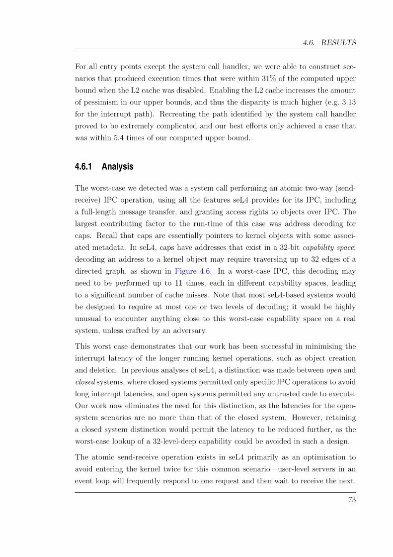
4.6. RESULTS
For all entry points except the system call handler, we were able to construct sce-
narios that produced execution times that were within 31% of the computed upper
bound when the L2 cache was disabled. Enabling the L2 cache increases the amount
of pessimism in our upper bounds, and thus the disparity is much higher (e.g. 3.13
for the interrupt path). Recreating the path identified by the system call handler
proved to be extremely complicated and our best efforts only achieved a case that
was within 5.4 times of our computed upper bound.
4.6.1 Analysis
The worst-case we detected was a system call performing an atomic two-way (send-
receive) IPC operation, using all the features seL4 provides for its IPC, including
a full-length message transfer, and granting access rights to objects over IPC. The
largest contributing factor to the run-time of this case was address decoding for
caps. Recall that caps are essentially pointers to kernel objects with some associ-
ated metadata. In seL4, caps have addresses that exist in a 32-bit capability space;
decoding an address to a kernel object may require traversing up to 32 edges of a
directed graph, as shown in Figure 4.6. In a worst-case IPC, this decoding may
need to be performed up to 11 times, each in different capability spaces, leading
to a significant number of cache misses. Note that most seL4-based systems would
be designed to require at most one or two levels of decoding; it would be highly
unusual to encounter anything close to this worst-case capability space on a real
system, unless crafted by an adversary.
This worst case demonstrates that our work has been successful in minimising the
interrupt latency of the longer running kernel operations, such as object creation
and deletion. In previous analyses of seL4, a distinction was made between open and
closed systems, where closed systems permitted only specific IPC operations to avoid
long interrupt latencies, and open systems permitted any untrusted code to execute.
Our work now eliminates the need for this distinction, as the latencies for the open-
system scenarios are no more than that of the closed system. However, retaining
a closed system distinction would permit the latency to be reduced further, as the
worst-case lookup of a 32-level-deep capability could be avoided in such a design.
The atomic send-receive operation exists in seL4 primarily as an optimisation to
avoid entering the kernel twice for this common scenario—user-level servers in an
event loop will frequently respond to one request and then wait to receive the next.
73

CHAPTER 4. FORMAL VERIFICATION VS INTERRUPT LATENCY
Object B
0 1
0 1
0 1
0 1
0 1
0 1
Object A
Figure 4.6: A worst-case address decoding scenario uses a capability space that re-quires a separate lookup for each bit of an address. Here, a binary address010...0 would decode to object A, but may need to traverse up to 32levels of this structure to do so.
If necessary, the execution time of this operation could be almost halved either by
inserting a preemption point between the send and receive phases, or by simply
forcing the user to invoke the send and receive phases separately. This latter ap-
proach would be detrimental to average-case throughput. We investigate placing a
preemption point between the two phases in Section 5.3.6 of the following chapter.
Other entry points to the kernel show no unexpected pathological cases; these entry
points are largely deterministic and have little branching. Like the IPC operations,
the worst case for these require decoding a capability that exists 32 levels deep in
the capability space. However only one such capability needs to be decoded in the
other exception handlers (to the thread which will handle the exception).
The improvements outlined in this chapter do not significantly affect the best- or
average-case execution time of the kernel, because IPCs are the most frequent op-
erations in microkernel-based systems. seL4 already provides fastpaths to improve
the performance of common IPC operations by an order of magnitude—fastpaths
are highly-optimised code paths designed to execute a specific operation as quickly
as possible. The fastpath performance is not affected by our preemption points. In
74
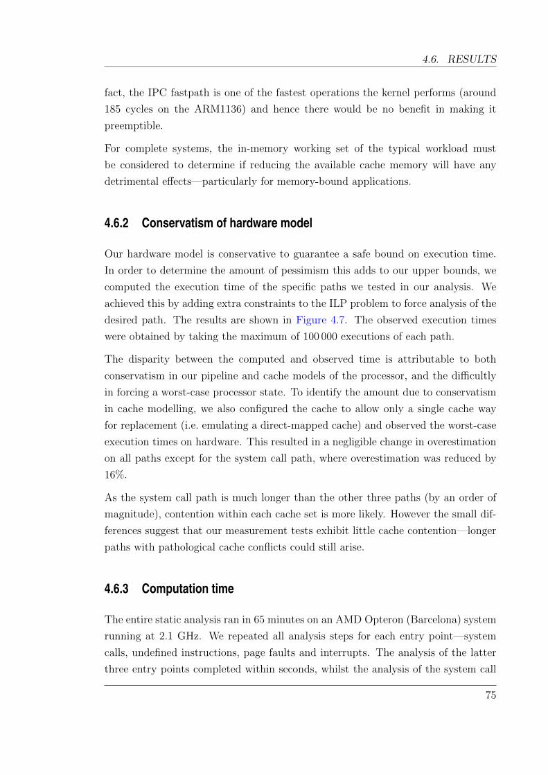
4.6. RESULTS
fact, the IPC fastpath is one of the fastest operations the kernel performs (around
185 cycles on the ARM1136) and hence there would be no benefit in making it
preemptible.
For complete systems, the in-memory working set of the typical workload must
be considered to determine if reducing the available cache memory will have any
detrimental effects—particularly for memory-bound applications.
4.6.2 Conservatism of hardware model
Our hardware model is conservative to guarantee a safe bound on execution time.
In order to determine the amount of pessimism this adds to our upper bounds, we
computed the execution time of the specific paths we tested in our analysis. We
achieved this by adding extra constraints to the ILP problem to force analysis of the
desired path. The results are shown in Figure 4.7. The observed execution times
were obtained by taking the maximum of 100 000 executions of each path.
The disparity between the computed and observed time is attributable to both
conservatism in our pipeline and cache models of the processor, and the difficultly
in forcing a worst-case processor state. To identify the amount due to conservatism
in cache modelling, we also configured the cache to allow only a single cache way
for replacement (i.e. emulating a direct-mapped cache) and observed the worst-case
execution times on hardware. This resulted in a negligible change in overestimation
on all paths except for the system call path, where overestimation was reduced by
16%.
As the system call path is much longer than the other three paths (by an order of
magnitude), contention within each cache set is more likely. However the small dif-
ferences suggest that our measurement tests exhibit little cache contention—longer
paths with pathological cache conflicts could still arise.
4.6.3 Computation time
The entire static analysis ran in 65 minutes on an AMD Opteron (Barcelona) system
running at 2.1 GHz. We repeated all analysis steps for each entry point—system
calls, undefined instructions, page faults and interrupts. The analysis of the latter
three entry points completed within seconds, whilst the analysis of the system call
75
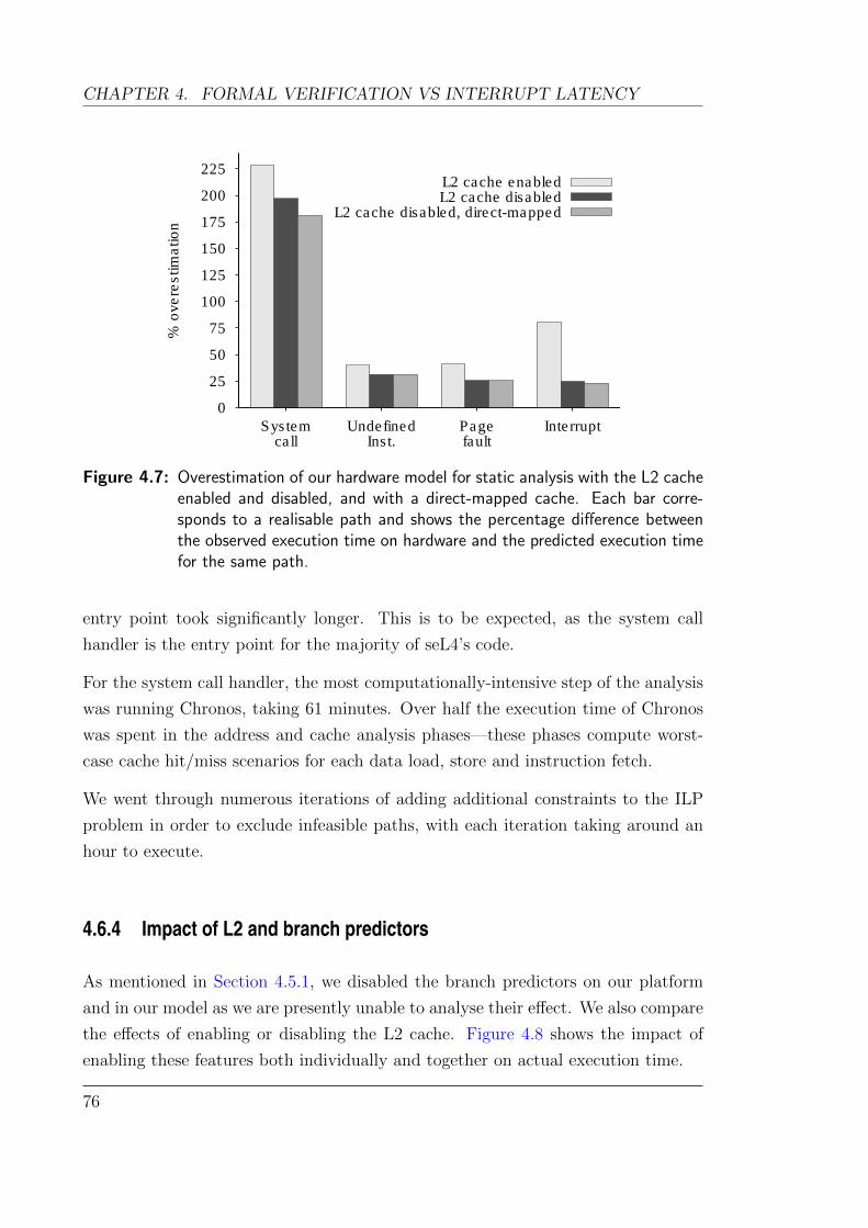
CHAPTER 4. FORMAL VERIFICATION VS INTERRUPT LATENCY
0
25
50
75
100
125
150
175
200
225
Systemcall
UndefinedInst.
Pagefault
Interrupt
% o
vere
stim
ation
L2 cache enabledL2 cache disabled
L2 cache disabled, direct-mapped
Figure 4.7: Overestimation of our hardware model for static analysis with the L2 cacheenabled and disabled, and with a direct-mapped cache. Each bar corre-sponds to a realisable path and shows the percentage difference betweenthe observed execution time on hardware and the predicted execution timefor the same path.
entry point took significantly longer. This is to be expected, as the system call
handler is the entry point for the majority of seL4’s code.
For the system call handler, the most computationally-intensive step of the analysis
was running Chronos, taking 61 minutes. Over half the execution time of Chronos
was spent in the address and cache analysis phases—these phases compute worst-
case cache hit/miss scenarios for each data load, store and instruction fetch.
We went through numerous iterations of adding additional constraints to the ILP
problem in order to exclude infeasible paths, with each iteration taking around an
hour to execute.
4.6.4 Impact of L2 and branch predictors
As mentioned in Section 4.5.1, we disabled the branch predictors on our platform
and in our model as we are presently unable to analyse their effect. We also compare
the effects of enabling or disabling the L2 cache. Figure 4.8 shows the impact of
enabling these features both individually and together on actual execution time.
76
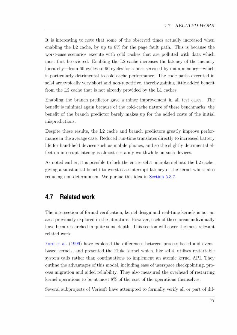
4.7. RELATED WORK
It is interesting to note that some of the observed times actually increased when
enabling the L2 cache, by up to 8% for the page fault path. This is because the
worst-case scenarios execute with cold caches that are polluted with data which
must first be evicted. Enabling the L2 cache increases the latency of the memory
hierarchy—from 60 cycles to 96 cycles for a miss serviced by main memory—which
is particularly detrimental to cold-cache performance. The code paths executed in
seL4 are typically very short and non-repetitive, thereby gaining little added benefit
from the L2 cache that is not already provided by the L1 caches.
Enabling the branch predictor gave a minor improvement in all test cases. The
benefit is minimal again because of the cold-cache nature of these benchmarks; the
benefit of the branch predictor barely makes up for the added costs of the initial
mispredictions.
Despite these results, the L2 cache and branch predictors greatly improve perfor-
mance in the average case. Reduced run-time translates directly to increased battery
life for hand-held devices such as mobile phones, and so the slightly detrimental ef-
fect on interrupt latency is almost certainly worthwhile on such devices.
As noted earlier, it is possible to lock the entire seL4 microkernel into the L2 cache,
giving a substantial benefit to worst-case interrupt latency of the kernel whilst also
reducing non-determinism. We pursue this idea in Section 5.3.7.
4.7 Related work
The intersection of formal verification, kernel design and real-time kernels is not an
area previously explored in the literature. However, each of these areas individually
have been researched in quite some depth. This section will cover the most relevant
related work.
Ford et al. (1999) have explored the differences between process-based and event-
based kernels, and presented the Fluke kernel which, like seL4, utilises restartable
system calls rather than continuations to implement an atomic kernel API. They
outline the advantages of this model, including ease of userspace checkpointing, pro-
cess migration and aided reliability. They also measured the overhead of restarting
kernel operations to be at most 8% of the cost of the operations themselves.
Several subprojects of Verisoft have attempted to formally verify all or part of dif-
77
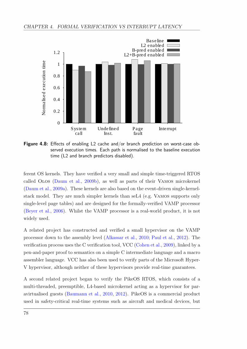
CHAPTER 4. FORMAL VERIFICATION VS INTERRUPT LATENCY
0
0.2
0.4
0.6
0.8
1
1.2
Systemcall
UndefinedInst.
Pagefault
Interrupt
No
rma
lise
d e
xe
cu
tio
n t
ime
BaselineL2 enabled
B-pred enabledL2+B-pred enabled
Figure 4.8: Effects of enabling L2 cache and/or branch prediction on worst-case ob-served execution times. Each path is normalised to the baseline executiontime (L2 and branch predictors disabled).
ferent OS kernels. They have verified a very small and simple time-triggered RTOS
called Olos (Daum et al., 2009b), as well as parts of their Vamos microkernel
(Daum et al., 2009a). These kernels are also based on the event-driven single-kernel-
stack model. They are much simpler kernels than seL4 (e.g. Vamos supports only
single-level page tables) and are designed for the formally-verified VAMP processor
(Beyer et al., 2006). Whilst the VAMP processor is a real-world product, it is not
widely used.
A related project has constructed and verified a small hypervisor on the VAMP
processor down to the assembly level (Alkassar et al., 2010; Paul et al., 2012). The
verification process uses the C verification tool, VCC (Cohen et al., 2009), linked by a
pen-and-paper proof to semantics on a simple C intermediate language and a macro
assembler language. VCC has also been used to verify parts of the Microsoft Hyper-
V hypervisor, although neither of these hypervisors provide real-time guarantees.
A second related project began to verify the PikeOS RTOS, which consists of a
multi-threaded, preemptible, L4-based microkernel acting as a hypervisor for par-
avirtualised guests (Baumann et al., 2010, 2012). PikeOS is a commercial product
used in safety-critical real-time systems such as aircraft and medical devices, but
78
4.8. SUMMARY
there has been no indication of a sound worst-case interrupt latency analysis.
Some progress has been made towards verifying code that executes in the presence
of interrupts. Feng et al. (2008) have constructed a framework on which to reason
about OS code in the presence of interrupts and preemption. Gotsman and Yang
(2011) have also constructed frameworks for verifying preemptible and multiproces-
sor kernels, and have used theirs to verify an OS scheduler.
Chapman et al. (1994) propose the idea of reusing a proof system and the invariants
proven within it to aid worst-case timing analysis. They use symbolic execution
to analyse a program in order to compute verification conditions for correctness
proofs, and compute path conditions for timing analysis. They use SPARK Ada
which integrates partial proof information such as pre- and post- conditions into the
language. Although this idea has promise, their paper describes a work-in-progress
implementation that does not appear to have been completed.
Klein (2009) provides thorough overview of the state of formal verification of oper-
ating systems.
4.8 Summary
In this chapter we have explored how to reduce the worst-case interrupt response
time of a verified protected microkernel such as seL4. We have added preemp-
tion points into some of seL4’s operations, and have restructured others in order
to remove all non-preemptible long-running operations from the kernel. These im-
provements have been guided by an analysis of the kernel’s worst-case execution
time.
From its inception, the design of seL4 was intended to limit interrupt latency to
short bounded operations, although this was not true of the original implementation.
Using static analysis to compute interrupt latencies, we could systematically validate
and improve the design where necessary.
As a verified microkernel, seL4 imposes additional constraints on how preemption
may be introduced. We must take care when adding preemption points to ensure
that the effort of re-verifying the kernel is minimised. This effort can be reduced
by avoiding unnecessary violations of global kernel invariants, and searching for
intermediate states that are generally consistent with the kernel’s normal execution.
79
CHAPTER 4. FORMAL VERIFICATION VS INTERRUPT LATENCY
With careful placement of preemption points, we have eliminated large interrupt
latencies caused by longer running operations inside seL4. This enables seL4 to host
execution of untrusted code, confined by the capabilities given to it, and still safely
meet real-time deadlines within 189 117 cycles. On modern embedded hardware
this translates to a few hundred microseconds, which is ample for many real-time
applications.
The biggest issue with seL4’s design in terms of interrupt latency, is the decision to
use a versatile 32-bit capability addressing scheme—each of the 32 bits that need
to be decoded can theoretically lead to another cache miss, and decoding several
such addresses results in significant interrupt latencies. Practical systems can use
the seL4 authority model to prevent this scenario by not allowing an adversary the
ability to construct their own capability space.
We have shown that the event-based model of seL4 can offer sub-millisecond laten-
cies, making it acceptable for many real-time application domains. The event-based
model also brings the benefits of reduced kernel complexity. We assert that a process-
based kernel without preemption would attain interrupt latencies in the same order
of magnitude as the event-based model. A fully-preemptible process-based kernel
may attain much smaller latencies, but forgoes the possibility of formal verification
using present state-of-the-art techniques. We investigate this notion further in the
following chapter.
Verification technology may some day be able to reason about the correctness of
fully-preemptible kernels. Until then, a formally-verifiable event-based microkernel
such as seL4 provides a very high assurance platform on which safety-critical and
real-time systems can be confidently built.
80
Chapter 5
Limits of interrupt latency innon-preemptible kernels
This chapter is partly based on work published at APSys 2012 in which I was the primary author
(Blackham, Tang, and Heiser, 2012b). The analysis of the QNX microkernel in Section 5.4
was performed by Vernon Tang.
5.1 Overview
In the previous chapter, we saw that the interrupt latency of a non-preemptible
kernel could be limited to the order of hundreds of microseconds using a design that
employs the idea of incremental consistency and appropriately placed preemption
points. This is suitable for a large class of systems, but some systems demand even
shorter interrupt latencies—for example, high-end motion control systems require
response times in the order of tens of microseconds. Such applications presently use
a fully-preemptible RTOS, often without memory protection, to ensure interrupt
latency is minimised.
The interrupt latencies obtained in the previous chapter are an order of magnitude
worse than what these application domains require. However, we were working under
the additional constraint that the resulting kernel code could still be functionally
verified, something that is presently not achievable at all for preemptible kernels.
A fully-preemptible kernel design exhibits lower average-case latencies but they do
so at a cost: RTOS code must be reentrant and is full of critical sections, which
81
CHAPTER 5. INTERRUPT LATENCY IN NON-PREEMPTIBLE KERNELS
must be protected by locks. Not only do locks introduce run-time overhead (which
affects average-case performance), the resultant highly-concurrent code is difficult to
reason about and therefore highly error-prone, significantly increasing the potential
for obscure bugs which can be extremely hard to find and eliminate. We are facing
a trade-off between assurance and timeliness.
Mixed-criticality systems necessitate the use of isolation between components (and
the RTOS). In a protected-mode OS, hardware-imposed overheads significantly in-
crease the cost of switching between application and OS operation, and the cost of
switching between user contexts (e.g. to handle an interrupt destined for a partition
different from the one presently executing).
In fact, these hardware costs are in the order of dozens or even hundreds of cycles, in
the same magnitude as the (generally simple) functions performed by an RTOS. This
means that the cost of preempting the RTOS operation is similar to the time required
for letting it complete uninterrupted, resulting in a significant shift in performance
trade-offs compared to classical, unprotected RTOSes.
Yet, the belief persists in academia and industry that an RTOS must be fully pre-
emptible: for example, commercial RTOSes supporting memory protection, such
as QNX Neutrino (QNX), VxWorks (Wind River) and INTEGRITY (Green Hills
Software), are fully preemptible.
We claim that the perceived need for a fully-preemptible design of a protected RTOS
is a myth. Specifically, we assert that for mixed-criticality systems, or any system
employing dual-mode execution and memory protection, a non-preemptible design
can achieve acceptable worst-case performance for many applications, while remain-
ing much simpler (and therefore more trustworthy) and providing better average-case
performance. We claim that this is largely because of the inherently high costs of
delivering an interrupt to userspace, compared with in-kernel interrupt delivery.
In this chapter, we demonstrate modifications to the non-preemptible seL4 kernel to
significantly reduce its interrupt latency, and describe how preemption points can
be added with minimal performance impact (Section 5.3). We extrapolate this to
what could be hypothetically achieved with a dedicated engineered effort, and also
compare with the worst-case interrupt response time for a mature commercial fully-
preemptible RTOS, QNX Neutrino. The results are given in Section 5.5, showing
that the non-preemptible approach can achieve a guaranteed latency of under 50µs,
making it highly competitive for low-latency applications. This supports our claim
82

5.2. RELATED WORK
that there is no inherent advantage to the fully-preemptible design that would justify
the added complexity and reduced average-case performance.
5.2 Related work
Our work relates closely to previous experiments by Ford et al. (1999) on the Fluke
kernel. They found that a fully-preemptible kernel provided the lowest latency
for dispatching kernel threads, however their evaluation only addressed observable
latency using hardware measurements, and not necessarily the true worst cases. The
analyses presented in this thesis use static analysis to compute safe upper bounds on
the worst-case latency, which can be relied upon for hard real-time systems. Ford
also measure latencies only on long IPC operations, and add preemption points
only for IPCs. Our results find that while IPC is a bottleneck, there exist other
long-running kernel operations which are more difficult to preempt.
Swartzendruber (1994) investigated making the Mach microkernel fully-preemptible,
by reusing the work that had been done to support multi-processor systems. He
observed that a multi-processor-capable kernel is easier to migrate to be fully-
preemptible, by reusing existing locking protocols as critical sections for a preempt-
ible uni-processor kernel. Although neither latency or performance were measured,
he estimated that uni-processor performance would decrease by roughly 10 %.
The monolithic Linux kernel originally used a non-preemptible design, but has
evolved incrementally towards increased preemptibility. McKenney provides a good
summary of the various attempts to retrofit real-time behaviour onto a Linux kernel.
For mixed-criticality real-time systems, the only viable approaches are those taken
by projects such as L4Linux (Hartig et al., 1998), where Linux is ported to run para-
virtualised on top of a real-time capable microkernel. This approach sidesteps the
preemptibility issue of Linux entirely, whilst reducing the trusted computing base.
We note that seL4 also supports running para-virtualised Linux as an unprivileged
user process.
We are not aware of any work which considers the extent to which worst-case latency
can be reduced in a non-preemptible kernel.
83
CHAPTER 5. INTERRUPT LATENCY IN NON-PREEMPTIBLE KERNELS
5.3 A non-preemptible kernel
We choose to adapt seL4 as our non-preemptible target, primarily because we al-
ready have a working worst-case execution time analysis workflow for seL4, as de-
scribed in previous chapters. Starting with the results achieved in Chapter 4, we
perform a series of modifications to seL4 to reduce its interrupt latency further,
dropping the requirement of formal verification. Forgoing this requirement enables
optimisations such as more liberal use of preemption points, and other common C
optimisation tricks.
Given the proliferation of preemption points, minimising their impact on worst-case
and average-case performance is an important goal. Section 5.3.1 describes how
preemption points can be implemented with minimal impact. Subsequent sections
elaborate on the changes made, analysing what bottlenecks need to be overcome to
improve real-time performance.
5.3.1 Minimal impact preemption points
We have seen that introducing preemption points into a non-preemptible kernel
allows the interrupt latency to be bounded and reduced when executing long code
paths. However, there are a number of ways to implement them, each with their
own trade-offs in the design space. The features and timing characteristics of the
target hardware often influence the best choice of implementation for a kernel. For
example, some hardware imposes a much higher cost to poll for pending interrupts
than to simply take the interrupt. On some CPUs, disabling and enabling interrupts
can also be expensive operations, taking dozens of cycles or more.
The following sections describe three possible implementations of preemption points
for non-preemptible kernels.
Explicitly enabling interrupts
One possible method runs the kernel with interrupts disabled. Within long-running
loops, the state of the kernel is made consistent at the end of each loop iteration
(leveraging the principle of incremental consistency described in Section 4.2.3). Once
consistent, the kernel can enable interrupts and then immediately disable them.
84
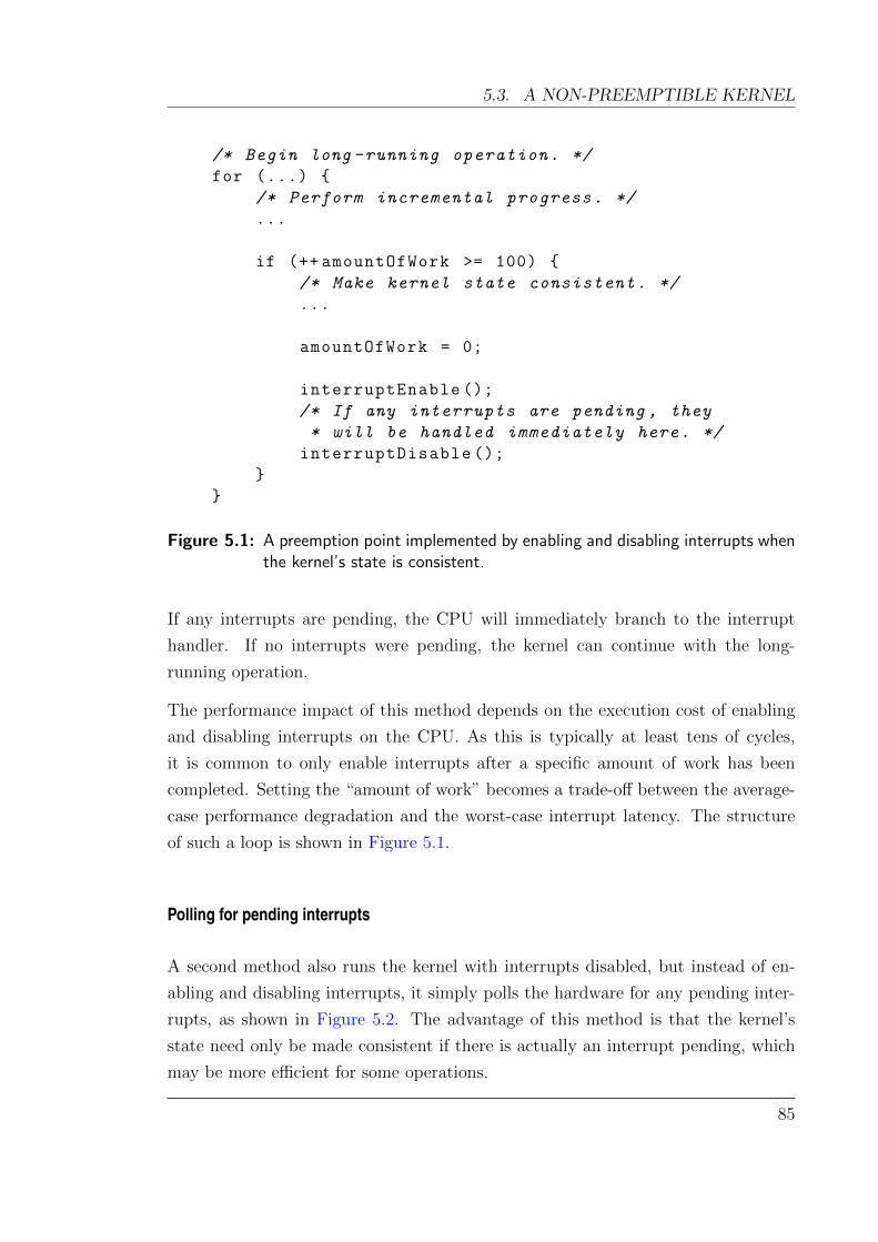
5.3. A NON-PREEMPTIBLE KERNEL
/* Begin long -running operation. */
for (...)
/* Perform incremental progress. */
...
if (++ amountOfWork >= 100)
/* Make kernel state consistent. */
...
amountOfWork = 0;
interruptEnable ();
/* If any interrupts are pending , they
* will be handled immediately here. */
interruptDisable ();
Figure 5.1: A preemption point implemented by enabling and disabling interrupts whenthe kernel’s state is consistent.
If any interrupts are pending, the CPU will immediately branch to the interrupt
handler. If no interrupts were pending, the kernel can continue with the long-
running operation.
The performance impact of this method depends on the execution cost of enabling
and disabling interrupts on the CPU. As this is typically at least tens of cycles,
it is common to only enable interrupts after a specific amount of work has been
completed. Setting the “amount of work” becomes a trade-off between the average-
case performance degradation and the worst-case interrupt latency. The structure
of such a loop is shown in Figure 5.1.
Polling for pending interrupts
A second method also runs the kernel with interrupts disabled, but instead of en-
abling and disabling interrupts, it simply polls the hardware for any pending inter-
rupts, as shown in Figure 5.2. The advantage of this method is that the kernel’s
state need only be made consistent if there is actually an interrupt pending, which
may be more efficient for some operations.
85
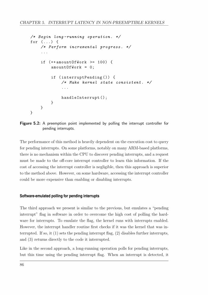
CHAPTER 5. INTERRUPT LATENCY IN NON-PREEMPTIBLE KERNELS
/* Begin long -running operation. */
for (...)
/* Perform incremental progress. */
...
if (++ amountOfWork >= 100)
amountOfWork = 0;
if (interruptPending ())
/* Make kernel state consistent. */
...
handleInterrupt ();
Figure 5.2: A preemption point implemented by polling the interrupt controller forpending interrupts.
The performance of this method is heavily dependent on the execution cost to query
for pending interrupts. On some platforms, notably on many ARM-based platforms,
there is no mechanism within the CPU to discover pending interrupts, and a request
must be made to the off-core interrupt controller to learn this information. If the
cost of accessing the interrupt controller is negligible, then this approach is superior
to the method above. However, on some hardware, accessing the interrupt controller
could be more expensive than enabling or disabling interrupts.
Software-emulated polling for pending interrupts
The third approach we present is similar to the previous, but emulates a “pending
interrupt” flag in software in order to overcome the high cost of polling the hard-
ware for interrupts. To emulate the flag, the kernel runs with interrupts enabled.
However, the interrupt handler routine first checks if it was the kernel that was in-
terrupted. If so, it (1) sets the pending interrupt flag, (2) disables further interrupts,
and (3) returns directly to the code it interrupted.
Like in the second approach, a long-running operation polls for pending interrupts,
but this time using the pending interrupt flag. When an interrupt is detected, it
86

5.3. A NON-PREEMPTIBLE KERNEL
/* Begin long -running operation. */
for (...)
/* Perform incremental progress. */
...
if (interruptPending == true)
/* Make kernel state consistent. */
...
handleInterrupt ();
Figure 5.3: A preemption point implemented by a software-emulated pending interruptflag.
makes the kernel’s state consistent so that the interrupt can be handled, as shown
in Figure 5.3. The common case now contains no slow interrupt-management code.
The pending interrupt flag check is a single memory access which by its nature will
almost always be hot in the CPU’s L1 cache.1 This also means that “amount of
work” counter seen in the previous two approaches is no longer necessary, as it serves
no benefit here.
The impact on the average case performance is reduced to a hot-cache memory load,
an arithmetic comparison and an untaken branch. On a typical ARM platform such
as the ARM1136, hot-cache accesses are single-cycle (although with a 3-cycle load
delay) and correctly predicted branches are folded (i.e. completely removed from
the instruction stream). For a well-crafted (or well-compiled) loop which avoids
the pipeline stall created by the memory load, the average-case execution time per
iteration can be as little as two cycles greater than the equivalent non-preemptible
code section.
It is easy to be enamored with the elegance of this approach to preemption points.
However, there are ugly artefacts of real-world systems and CPUs which mean de-
velopers need to be careful when implementing this. Namely, numerous ARM imple-
mentations have errata which can cause incorrect behaviour, or even deadlock the
CPU, if interrupts arrive at inopportune times during certain system operations.
1 Strategic data placement can ensure the address of this flag can be easily computed (and thusdoes not require an additional literal load), reducing excess register pressure, as well as minimisingthe impact on the kernel’s cache footprint.
87
CHAPTER 5. INTERRUPT LATENCY IN NON-PREEMPTIBLE KERNELS
Running the kernel with interrupts enabled by default means that special care must
be taken to ensure that such errata cases cannot occur, typically by disabling inter-
rupts before issuing the offending operations. Note that this is no different from the
level of care which would be required when implementing a fully-preemptible kernel.
A note on verifiability
The first two approaches align with the existing seL4 verification, as the single-
threaded nature of the kernel is maintained, and the interrupt-specific functions
are modelled as non-deterministic inputs. In fact, the second approach is what is
currently used by the verified seL4 kernel.
It is not clear how to integrate the third approach into the high-assurance verification
of the seL4 kernel, as the verification assumes that all code executes sequentially.
Enabling interrupts during execution breaks a fundamental assumption of the proof.
Despite that, it could be proven that the interrupt handler itself has no visible effects
on the state of the system (beyond the pending interrupt flag). Combined with a
proof of kernel correctness that assumes single-threaded execution, this gives a strong
guarantee that the system still behaves as specified.
Of course, as described earlier, it is possible that hardware bugs and errata may
partly undermine these guarantees, but this remains a problem for any system,
notably fully-preemptible systems.
For the analysis performed in this chapter and presented in Section 5.5, we imple-
ment the third approach in the seL4 microkernel.
5.3.2 Preserving the fastpath
In order to achieve good performance, microkernel-based systems rely on very fast
IPC operations, typically provided by IPC fastpaths (Liedtke et al., 1997; Blackham
and Heiser, 2012). A fastpath usually improves IPC times by orders of magnitude, as
it handles only the most commonly executed operations, deferring other operations
to the conventional slowpath. As adding preemption points in a code path generally
increases its uninterrupted execution time, making the IPC fastpath preemptible
would degrade average-case performance.
88

5.3. A NON-PREEMPTIBLE KERNEL
The IPC fastpath in seL4 has already been heavily optimised for fast context switch-
ing. Given this, we can aim to reduce the kernel’s overall interrupt latency down
to that of the WCET of the fastpath, as there is little benefit from going further.
There may be other limitations on how low the interrupt latency can be made, but
the WCET of the fastpath certainly marks the point beyond which there will be
diminishing returns.
5.3.3 Removing capability addressing
Our previous analysis of seL4 identified the longest execution path being a worst-case
IPC operation. As described in Section 4.6.1, seL4’s flexible capability addressing
creates a worst case of hundreds of cache misses on certain IPC operations.
The WCET for seL4 is improved drastically by forgoing its flexible capability ad-
dressing scheme, ensuring that all capabilities can be resolved by traversing only a
single level within the capability space (not 32 as was previously possible). Most
RTOSes do not offer anything comparable to the flexible addressing scheme of seL4.
At worst this makes seL4’s addressing on par with other RTOSes, where a single
level of indirection is typically used to address kernel objects.
By limiting the lookup depth to just one level, we reduce the number of potential
cache misses caused by address lookups by a factor of 32.
5.3.4 Global kernel mapping copy
The seL4 kernel is mapped into virtual memory in the top 256 MiB of every address
space on the system. This mapping is represented by 1 KiB of data in every page
directory, which must be copied each time a new page directory is created. The
process of copying these mappings was non-preemptible and therefore a contributor
to potentially long execution times. The seL4 proof depends on having a flat 1:1
mapping of physical memory, as it cannot reason about the safety of mapping or
unmapping kernel pages in which seL4 itself may be executing. However, beyond
the proof, the kernel is not intrinsically linked to this model.
Possible solutions to overcome the copy latency include:
1. simply adding preemption points to the copy operation;
89
CHAPTER 5. INTERRUPT LATENCY IN NON-PREEMPTIBLE KERNELS
2. moving the entire seL4 kernel into its own 32-bit address space;
3. lazily populating the address space as the kernel faults on memory accesses
within the kernel mapping; or
4. reducing the size of the global kernel mapping.
The first solution impacts many parts of the kernel, as address space objects must
now be checked for completeness before being used, or alternately an intermediate
object type could be added. Either approach increases the complexity of kernel
invariants, and therefore the verification process. The second solution simplifies the
kernel, avoiding the address space copy entirely. However, it also impacts negatively
on overall performance, as a context switch is then required for every kernel entry
and exit.
The third solution is very difficult to verify within the seL4 proof, as the proof
assumes that faults do not occur inside the kernel. It is relatively straightforward to
implement though, and has negligible run-time overhead. However it does increase
the worst-case execution time, as memory accesses can now induce an additional
fault. We chose to implement this option. As the code to map a kernel page on
fault is hand-coded in assembly, it runs very efficiently and its impact can be easily
bounded.
The final possible solution, reducing the size of global kernel mapping, requires
dynamically mapping and unmapping memory frames containing kernel objects as
they are required. This allows the size of the global kernel mapping to shrink to only
a few megabytes—the kernel code itself and all its internal global data structures
sum to at most a few hundred kilobytes. This approach is effectively equivalent to
the third solution (lazily populating the address space), as the kernel maps pages
only as they need to be accessed. However, the average-case performance and kernel
complexity suffer, because mapping operations must be done explicitly on every
access to any kernel object.
5.3.5 Breaking long code paths
Despite making all loops within seL4 preemptible using preemption points, there are
still large sections of loop-free code which contribute to long worst-case execution
times (over 100µs). We analysed the offending code paths, and found that none of
90
5.3. A NON-PREEMPTIBLE KERNEL
the long paths required atomicity—they were simply performing multiple operations,
which could theoretically be implemented as separate calls.
For example, seL4 offers a system call which configures several independent aspects
of a thread—its address space, its capability space, its IPC buffer and its priority.
Calls such as this exhibit the incremental consistency property, because they perform
several small updates, whilst retaining global consistency of kernel data structures
between changes. It is easy to make them preemptible by adding preemption points
between each of the steps, and we do so for the analysis described later in Section 5.5.
5.3.6 Non-preemptible IPC
Another contributor to worst-case interrupt latency was the seL4 IPC slowpath,
which is used for copying messages between communicating processes. We do not
wish to make the slowpath preemptible, as this would require adding complexity
to the IPC fastpath, which would significantly impact average-case system perfor-
mance.
With non-preemptible IPC, the maximum length of an IPC message is a convenient
variable which can be tuned to alter the kernel’s worst-case latency. Shorter IPCs
will reduce the bandwidth between communicating processes, but for applications
requiring high-bandwidth communication, shared memory regions are a more ap-
propriate choice. Of course, there is some minimum message length required to
maintain reasonable system performance, which is application-dependent.
To minimise latency, the maximum IPC length should be chosen so that the WCET
of an IPC is equal to the largest WCET of any other kernel operation. Reducing
it below this value provides no benefit, while raising it above this value directly
increases the worst-case latency. Given this, we reduce the maximum message length
of seL4 to from 480 bytes to 240 bytes.
If every other kernel operation’s WCET could be made fast enough that the equiva-
lent IPC lengths were too short (and causing performance issues), then preemptible
IPC may need to be reconsidered. Otherwise it is a premature optimisation.
Another issue affecting seL4 was a specific IPC operation known as ReplyWait, which
atomically performs the functionality of two operations commonly called together:
Reply (send) and Wait (receive). The IPC fastpath relies on the atomicity of these
operations to significantly improve performance, as no scheduler interactions are
91
CHAPTER 5. INTERRUPT LATENCY IN NON-PREEMPTIBLE KERNELS
required. We expect that if an IPC operation falls back to the slowpath, there is
a negligible penalty in adding a preemption point between the send and receive
phases. Doing so effectively halves the WCET of this path.
There is still room for improvement in seL4 by making the copy operation more
efficient (e.g. with multi-word copies, using preloading tricks, etc). Doing so would
allow for longer IPCs, but would not reduce the worst-case latency of the kernel,
assuming the kernel adheres to the above rule to determine IPC length.
5.3.7 L2 cache pinning
Although CPUs have increased in performance by several orders of magnitude in
the past 30 years, memory latencies have not kept the same pace (Patterson, 2004).
Operations which are inherently memory-intensive and have unpredictable access
patterns have seen almost no benefit from newer technologies. The increased dis-
parity between CPU and memory speeds have pushed hardware manufacturers to
include one or more levels of caches even in embedded systems.
CPU caches can be accessed significantly faster than main memory. For example,
the KZM ARM11 platform has two levels of caches—the first can be accessed in
a single cycle and the second in 26 cycles, compared with external memory access
latencies of 96 cycles (with the L2 cache enabled).
Considering the effect of caches is a challenge for hard real-time systems as it in-
creases the gap between the worst case (which must be allowed for) and the average
case (which is the common operating point). To mitigate the unpredictability caused
by caches, many platforms provide the ability to pin data or instructions into the
cache. Pinned data and instructions are never evicted from the cache, and therefore
guarantee a shorter bound on access times.
As fast caches are typically much smaller than main memory, the choice of what to
pin must normally be made with great care. Pinning data into the cache precludes
the pinned portion of cache from being used for the rest of the system, where it may
actually be better utilised to improve average-case performance.
As microkernels are intended to provide the bare minimum functionality for ensuring
security of a system, they are typically very small. Our modified seL4 microkernel
executable can fit into 29.5 KiB. The L2 cache on our platform is 128 KiB, which
92
5.4. A FULLY-PREEMPTIBLE KERNEL
means that the entire kernel code fits into 1/4 of the L2 cache.2 It would be unlikely,
if not impossible, for monolithic kernels to fit into this space, nor even many larger
microkernels.
Given that we have gone to great lengths to make loops in the kernel preemptible,
the remaining non-preemptible code is likely to only ever execute once. There-
fore without cache pinning the worst-case execution time is never improved by the
cache—in the worst case, none of the kernel’s instructions are in the cache, and so
every execution path will encounter a swarm of cache misses.
By pinning the instructions into the L2 cache, the latency of L1 instruction cache
misses is reduced by 73 % on our platform. This drops the upper bound on CPU
time that is wasted waiting for memory, and therefore significantly improves the
worst-case execution time.
Furthermore, the interrupt delivery path can be pinned into the L1 cache to reduce
interrupt latency further, as was shown in Section 4.4.
Note that a fully-preemptible microkernel, if sufficiently small, could also employ
the same approach. However, we argue that because interrupt delivery paths in
both the fully-preemptible and non-preemptible designs are significant contributors
to response time, the improvements gained when applied to either approach would
be comparable.
5.4 A fully-preemptible kernel
As we know by now, the latency of userspace interrupt delivery on a kernel is de-
termined by two independent factors:
• the in-kernel dispatch latency: the latency between the arrival of an interrupt
to the CPU hardware and executing the in-kernel interrupt handler; and
• the kernel-userspace dispatch latency: the time taken between the in-kernel
interrupt handler executing and the start of the userspace interrupt handler.
For a “fully-preemptible” kernel, the in-kernel dispatch latency is determined by
all code paths where interrupts are disabled—these are mostly between interrupt
2 The L2 cache on our platform permits pinning in multiples of 1/8 of the size of the cache, sofalling just under 1/4 of the cache minimises the amount of wasted memory.
93

CHAPTER 5. INTERRUPT LATENCY IN NON-PREEMPTIBLE KERNELS
disable/enable pairs used for concurrency control, but they can also arise where
the hardware may disable interrupts (e.g. on the transition from user mode into
kernel mode upon an exception). A carefully designed fully-preemptible kernel can
minimise this latency for many operations; however, the critical aspect is the worst
case—i.e. the longest of any such paths. Most importantly, avoiding unbounded
non-preemptible loops is crucial for bounding interrupt latency.
The kernel-userspace dispatch latency is affected by both the design of the kernel and
inherent limitations of the hardware’s context switching and interrupt processing
time. These considerations are shared by fully-preemptible and non-preemptible
kernel designs alike.
There are several commercial fully-preemptible, general-purpose kernels used in real-
time systems today, such as QNX Neutrino (QNX), VxWorks (Wind River) and
INTEGRITY (Green Hills Software). Most high-performance microkernels are com-
mercial endeavours and the cost of obtaining binaries for these is often substantial.
Their sources are considered to be of great commercial value, thus getting access to
the source for independent analysis is nearly impossible.
One we were able to get access to was the QNX Neutrino microkernel. The QNX
sources were made publicly available in 2008, and binaries are also available. Al-
though our WCET analysis works on the compiled binary, the availability of source
code was crucial—the analysis required a significant amount of manual intervention,
which benefited substantially from the understanding of QNX’s internals gleaned
from the source code.
We analyse the QNX Neutrino microkernel and use it as a representative of the
fully-preemptible approach due to its maturity and broad real-world adoption.
5.4.1 “Fully-preemptible” vs “fully-preemptible”
In the traditional RTOS mindset, a fully-preemptible kernel can execute an interrupt
handler with very short latencies because interrupts are rarely disabled. However,
this ability generally extends only to interrupt handlers that run within the kernel.
In a mixed-criticality system, in-kernel interrupt handlers are unacceptable, as an
error in an interrupt handler can crash the entire system. In order for the kernel
of a mixed-criticality system to be considered fully-preemptible, not only must the
kernel run with interrupts enabled, but upon receiving an interrupt, it must be able
94
5.4. A FULLY-PREEMPTIBLE KERNEL
to dispatch that interrupt to userspace immediately.
We note that the design of QNX is not actually suited to mixed-criticality systems—
although QNX is fully-preemptible by the traditional RTOS definition, the schedul-
ing of a userspace interrupt handler can be delayed, not just by regions where inter-
rupts are disabled, but also by any code that “locks” the kernel.
In QNX, the kernel must be locked before performing any non-idempotent modi-
fication to the kernel state (e.g. a heap allocation). When the kernel is executing
unlocked, any interrupt can preempt the current operation to schedule a userspace
thread. The preempted operation is simply restarted later. However, if an interrupt
arrives when the kernel is locked, a userspace thread cannot be scheduled until the
kernel operation is completed.
A brief inspection of QNX shows that several code paths which execute when locked
contain unbounded loops that are dependent on system state (e.g. paths which
are affected by the amount of heap fragmentation). The worst-case response time
must consider all such code paths in the kernel, significantly complicating a worst-
case execution time analysis. This design is perfectly reasonable for the traditional
RTOS model where interrupts are largely handled within the kernel. However, for
mixed-criticality systems, userspace interrupt delivery must have bounded interrupt
latency guarantees.
Despite not being suitable for mixed-criticality systems, we use QNX Neutrino as a
conservative representative of the fully-preemptible approach. We assume that the
kernel could be made fully-preemptible to userspace, and focus only on the userspace
interrupt delivery path of QNX as a measurable data point. This underestimates
the WCET that can be achieved by a true fully-preemptible kernel, as the overheads
of making a kernel support full preemption to userspace are not considered. As this
chapter proposes that the non-preemptible model can be competitive with fully-
preemptible kernels, this conservatism is in favour of the fully-preemptible kernel.
5.4.2 Analysis details
Our analysis is based on a binary of the QNX 6.5.0 kernel (the latest available at the
time), compiled for ARMv6 systems (QNX). We were guided by an older snapshot
of the source code from July 2009, as QNX sources are unfortunately no longer
available to the general public. Despite the disparity in versions, we were able to
95
CHAPTER 5. INTERRUPT LATENCY IN NON-PREEMPTIBLE KERNELS
use the sources to glean sufficient understanding of the binary for analysis.
Our analysis tools were originally designed for analysing seL4, and as such they
made some assumptions about the structure of analysed code. Some of these as-
sumptions proved to be invalid when analysing QNX, and required us to modify our
tools to support them. We found that many of the techniques employed by QNX
made static analysis more difficult. In particular, the presence of function pointers,
exception-defined control flow (e.g. instructions or memory accesses which are per-
mitted to cause exceptions) and dynamically-generated code required some manual
intervention in the analysis.
Control-flow graph extraction
Our analysis tools are able to automatically extract the control flow graph of seL4,
because there are no function pointers in the C code, and all branch instructions in
the binary can be resolved easily using simple symbolic execution. QNX, on the other
hand, uses function pointers extensively, making automated extraction infeasible.
Instead, we manually specified the targets of function pointers. Determining the
destination addresses of various function pointers was (unsurprisingly) significantly
easier with access to the source code.
As the QNX code base is far larger than seL4’s, we found the generated CFG
was prohibitively large and complex for our WCET analysis. To overcome this,
we limited the analysis to the smaller relevant fragments of the CFG, by forcing
specific branches to be marked as taken or ignored. We maintained the soundness
of our analysis by ensuring that the subset analysed contained the critical path for
interrupt delivery.
Our tools are still limited in what they can analyse, and we had to take a few short-
cuts. To ensure the validity of our hypothesis, our analysis always underestimates,
where necessary, the worst-case interrupt response time of QNX.
For instance, we ignored QNX’s support for sporadic scheduling, as this would have
significantly complicated our analysis; not ignoring this would only increase the
worst-case response time of QNX further. Furthermore, we found that QNX has
a suboptimal implementation of a priority queue (a sorted linked list with O(n)
complexity); we ignored this as there is obviously a better O(log n) implementation.
In addition to manually forcing specific branches as taken, it is also possible to au-
96
5.4. A FULLY-PREEMPTIBLE KERNEL
tomatically prune some infeasible branches using symbolic execution. Our existing
symbolic execution engine was previously only sufficient for determining the des-
tination address of branches. We have enhanced it to also take into account the
results of prior arithmetic operations (when known with certainty) so that it can
determine if a conditional branch will always be taken (or always not taken).
Analysing runtime-generated code
The QNX Neutrino RTOS follows a generic pattern in its design. For each supported
processor architecture (ARM, x86, etc.), QNX provides a single kernel binary named
procnto. QNX also provides generic board support package (BSP) code. System
integrators provide their own machine-specific code (for booting, hardware control,
etc.) using the QNX BSP code as a base.
A large proportion of the interrupt-handling code depends on the specifics of the ma-
chine. Unfortunately, QNX accomplishes this in a way that complicates the static
analysis process. At boot time, the interrupt vector code is dynamically gener-
ated based on the system’s interrupt topology, and is interspersed with integrator-
provided code to interface with the interrupt controllers. While this has allowed
QNX to ship a single binary that does not need static relocation or other build-
time transformations, it also means that the interrupt vector code is not directly
available.
We had observed that the generated interrupt vector code in memory did not change
after booting and so we were able to simply dump the generated code from a running
system. We proceeded with our analysis by re-assembling and linking the dumped
code with the rest of the procnto image. In this way, we were able to preserve
symbols, aiding in the maintenance of our manual annotations.
Event handling
QNX provides a number of different event delivery methods:
• Simply ignoring the event.
• Sending a POSIX signal to a given process or thread.
• Executing a given routine in a new thread.
97
CHAPTER 5. INTERRUPT LATENCY IN NON-PREEMPTIBLE KERNELS
• Forcing a blocked thread to resume (returning an ETIMEOUT error).
• Resuming a thread that was waiting on a MsgReceive system call.
• Resuming a thread that was waiting on an InterruptWait system call.
We chose only to consider the last of these methods, and then only the Interrupt-
Wait case (SIGEV INTR) in our analysis. This mechanism is functionally equivalent
to that used in seL4. More importantly, of the different interrupt delivery methods
available, it represents a best case and therefore a lower bound on the time required
to dispatch an interrupt to userspace code. Other methods, such as signal delivery
or thread creation, require significantly more work to process an interrupt, compared
with waking an existing blocked thread.
5.5 Results and analysis
5.5.1 Limits of a non-preemptible kernel
We compute the worst-case interrupt response time of the modified seL4 kernel
binary using our static analysis framework. The analysis method is similar to that
used in the previous chapter, but has been improved to incorporate the infeasible
path detection algorithm described in Chapter 7.
Also, unlike in the previous analyses, we do not treat preemptible loops as though
they have an iteration count of 1. Although this is a sound approximation, it
overestimates the interrupt response time of any path containing multiple loops. In
the case of a pending interrupt, only the first loop would execute in practice, whereas
our analysis assumed that both loops would execute once. The approach also fails
if preemption points are used outside of loops. These cases did not arise previously,
but with the proliferation of preemption points through seL4, our previous analysis
methods are no longer suitable.
In this analysis, we instead consider each preemption point separately. For each
preemption point, we compute the worst-case execution time between the preemp-
tion point and the beginning of a userspace interrupt handler thread (running at
the highest priority). These correspond to the worst-case scenarios of an interrupt
arriving immediately after a preemption point has found no pending interrupts. We
98
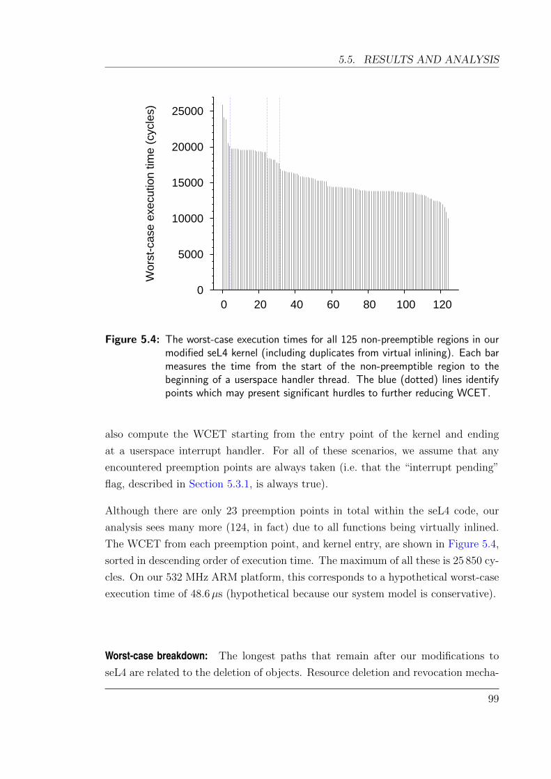
5.5. RESULTS AND ANALYSIS
0
5000
10000
15000
20000
25000
0 20 40 60 80 100 120
Wors
t-case e
xecution tim
e (
cycle
s)
Figure 5.4: The worst-case execution times for all 125 non-preemptible regions in ourmodified seL4 kernel (including duplicates from virtual inlining). Each barmeasures the time from the start of the non-preemptible region to thebeginning of a userspace handler thread. The blue (dotted) lines identifypoints which may present significant hurdles to further reducing WCET.
also compute the WCET starting from the entry point of the kernel and ending
at a userspace interrupt handler. For all of these scenarios, we assume that any
encountered preemption points are always taken (i.e. that the “interrupt pending”
flag, described in Section 5.3.1, is always true).
Although there are only 23 preemption points in total within the seL4 code, our
analysis sees many more (124, in fact) due to all functions being virtually inlined.
The WCET from each preemption point, and kernel entry, are shown in Figure 5.4,
sorted in descending order of execution time. The maximum of all these is 25 850 cy-
cles. On our 532 MHz ARM platform, this corresponds to a hypothetical worst-case
execution time of 48.6µs (hypothetical because our system model is conservative).
Worst-case breakdown: The longest paths that remain after our modifications to
seL4 are related to the deletion of objects. Resource deletion and revocation mecha-
99

CHAPTER 5. INTERRUPT LATENCY IN NON-PREEMPTIBLE KERNELS
nisms are often the most complicated part of any resource management system3 and
are common sources of system-state-dependent execution times (Colin and Puaut,
2001b; Singal and Petters, 2007).
The worst case for our modified seL4 is a specific instance of a deletion operation
for deleting a thread, which begins at the entry point of the kernel. As such, the
longest path includes (re-)validation of the arguments passed to the kernel, and
ensures that all relevant objects exist. In seL4, one stage of thread deletion requires
turning the thread into a zombie, which prevents the thread from executing or being
further manipulated by the user, and allows the deletion of any resources held by
the thread to proceed preemptibly. It is this scenario which incurs the worst-case.
The computed worst-case execution time of this operation is 25 850 cycles. A break-
down of the time spent in this operation is roughly as follows:
• 25% is devoted to decoding the system call and validating arguments from the
user;
• 30% is control code which decides what actions need to be taken (e.g. ensuring
there are no other references to the thread to be deleted);
• 12% is devoted to actually modifying kernel state (updating scheduler data
structures and turning the thread into a zombie); and
• 33% is spent dispatching the userspace interrupt handler.
The state modifications need to be done atomically, and they contribute a relatively
small fraction of the overall cost. Thus this path cannot be easily made shorter by
introducing a preemption point. Instead, one would need to micro-optimise the code
paths to reduce the cost of the validation and checks required for deletion.
Other operations which also exhibit a WCET of ∼ 25 000 cycles include unmapping
a frame from an address space, and replacing a thread’s IPC buffer. These have
similar execution profiles to thread deletion—i.e. small (non-preemptible) changes
to the kernel state, accompanied by lots of book keeping for deletion.
As described in Section 5.3.6, the length of an IPC was chosen in order to exhibit a
WCET of under 25 000 cycles.
3 It is interesting to note that the original seL4 object deletion code had to be rewritten anumber of times, when the formal verification process identified subtle flaws in several iterationsof the design. Preemptible deletion, it turns out, hides a lot of corner cases for the unwary.
100
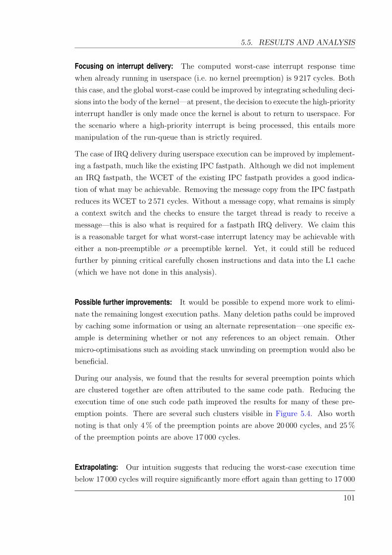
5.5. RESULTS AND ANALYSIS
Focusing on interrupt delivery: The computed worst-case interrupt response time
when already running in userspace (i.e. no kernel preemption) is 9 217 cycles. Both
this case, and the global worst-case could be improved by integrating scheduling deci-
sions into the body of the kernel—at present, the decision to execute the high-priority
interrupt handler is only made once the kernel is about to return to userspace. For
the scenario where a high-priority interrupt is being processed, this entails more
manipulation of the run-queue than is strictly required.
The case of IRQ delivery during userspace execution can be improved by implement-
ing a fastpath, much like the existing IPC fastpath. Although we did not implement
an IRQ fastpath, the WCET of the existing IPC fastpath provides a good indica-
tion of what may be achievable. Removing the message copy from the IPC fastpath
reduces its WCET to 2 571 cycles. Without a message copy, what remains is simply
a context switch and the checks to ensure the target thread is ready to receive a
message—this is also what is required for a fastpath IRQ delivery. We claim this
is a reasonable target for what worst-case interrupt latency may be achievable with
either a non-preemptible or a preemptible kernel. Yet, it could still be reduced
further by pinning critical carefully chosen instructions and data into the L1 cache
(which we have not done in this analysis).
Possible further improvements: It would be possible to expend more work to elimi-
nate the remaining longest execution paths. Many deletion paths could be improved
by caching some information or using an alternate representation—one specific ex-
ample is determining whether or not any references to an object remain. Other
micro-optimisations such as avoiding stack unwinding on preemption would also be
beneficial.
During our analysis, we found that the results for several preemption points which
are clustered together are often attributed to the same code path. Reducing the
execution time of one such code path improved the results for many of these pre-
emption points. There are several such clusters visible in Figure 5.4. Also worth
noting is that only 4 % of the preemption points are above 20 000 cycles, and 25 %
of the preemption points are above 17 000 cycles.
Extrapolating: Our intuition suggests that reducing the worst-case execution time
below 17 000 cycles will require significantly more effort again than getting to 17 000
101
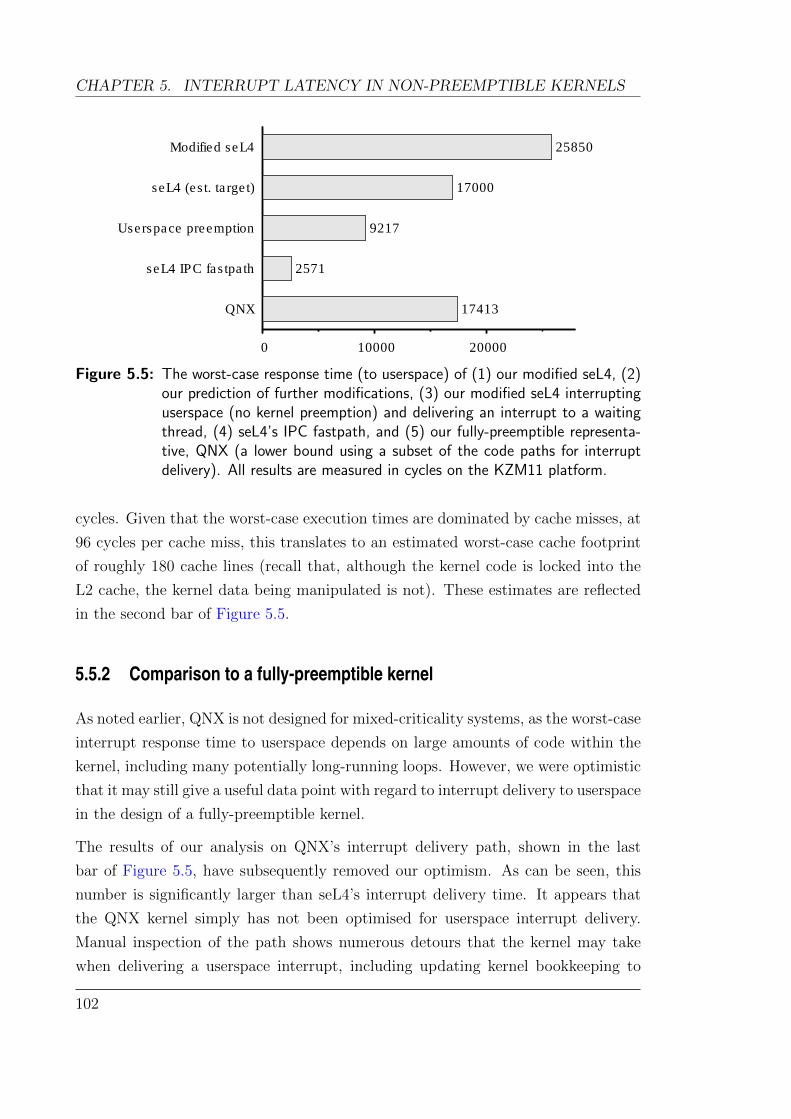
CHAPTER 5. INTERRUPT LATENCY IN NON-PREEMPTIBLE KERNELS
Modified seL4
seL4 (est. target)
Userspace preemption
seL4 IPC fastpath
QNX
0 10000 20000
25850
17000
9217
2571
17413
Figure 5.5: The worst-case response time (to userspace) of (1) our modified seL4, (2)our prediction of further modifications, (3) our modified seL4 interruptinguserspace (no kernel preemption) and delivering an interrupt to a waitingthread, (4) seL4’s IPC fastpath, and (5) our fully-preemptible representa-tive, QNX (a lower bound using a subset of the code paths for interruptdelivery). All results are measured in cycles on the KZM11 platform.
cycles. Given that the worst-case execution times are dominated by cache misses, at
96 cycles per cache miss, this translates to an estimated worst-case cache footprint
of roughly 180 cache lines (recall that, although the kernel code is locked into the
L2 cache, the kernel data being manipulated is not). These estimates are reflected
in the second bar of Figure 5.5.
5.5.2 Comparison to a fully-preemptible kernel
As noted earlier, QNX is not designed for mixed-criticality systems, as the worst-case
interrupt response time to userspace depends on large amounts of code within the
kernel, including many potentially long-running loops. However, we were optimistic
that it may still give a useful data point with regard to interrupt delivery to userspace
in the design of a fully-preemptible kernel.
The results of our analysis on QNX’s interrupt delivery path, shown in the last
bar of Figure 5.5, have subsequently removed our optimism. As can be seen, this
number is significantly larger than seL4’s interrupt delivery time. It appears that
the QNX kernel simply has not been optimised for userspace interrupt delivery.
Manual inspection of the path shows numerous detours that the kernel may take
when delivering a userspace interrupt, including updating kernel bookkeeping to
102

5.6. CONCLUSION
support re-entrancy.
We are unable to draw conclusive results from the analysis of QNX, particularly
as it does not support bounded preemption latencies to userspace when running
inside the kernel. However, we assert that a fully-preemptible kernel could achieve
similar worst-case userspace interrupt latencies to non-preemptible kernels for the
case when userspace is preempted, by using a non-preemptible IRQ delivery fast-
path. A non-preemptible fastpath means that the overall kernel interrupt latency
is at least double the worst-case latency of this fastpath (the worst-case is at least
that of the interrupt fastpath beginning execution when a higher priority interrupt
arrives, therefore needing to execute again). It remains to be seen if all other non-
preemptible kernel paths can be made this short.
5.6 Conclusion
This chapter has explored the limits of interrupt latency for a non-preemptible
kernel design. We also attempted a comparison with a fully-preemptible kernel,
which did not turn out to be fruitful as the selected kernel was not optimised for
mixed-criticality applications.
We made a number of changes to reduce the interrupt latency of the non-preemptible
seL4 microkernel from 100 000s of cycles, down to 25 850 cycles. The results suggest
that further improvements could reduce this to approximately 17 000 cycles. Using
low-overhead preemption points, this can be done without incurring any significant
performance penalty. To reduce this further requires rethinking the data structures
used for bookkeeping in the kernel. This is an opportunity for future research
directions.
We provide a lower bound on what may be achievable even by fully-preemptible ker-
nels, based on the worst-case execution time of a heavily optimised fastpath for IPC.
The difference between this limit and what was achieved with a non-preemptible ker-
nel differs by a factor of 10, but only by a factor of 6.6 to what may be achieved
with extra effort.
On a modest embedded processor such as our 532 MHz ARM11, our results provide
a guaranteed worst-case latency of 48.6µs. This would suffice for many applications
including standard industrial motion control applications. Our evidence suggests
103

CHAPTER 5. INTERRUPT LATENCY IN NON-PREEMPTIBLE KERNELS
that there is room to reduce this even further with careful kernel design.
Although we have forgone the immediate possibility of formal verification in order
to achieve these results, traditional validation methods, such as testing, code in-
spection, and model checking, can still be used. Even if not formally verified, the
resulting non-preemptible kernel is much less complex, and thus easier to assure
than a fully-preemptible one.
104

Chapter 6
Checking properties on binaries
This chapter is based on work published at RTAS 2013 in which I was the primary author
(Blackham and Heiser, 2013a).
6.1 Overview
Through the previous three chapters, we have performed a number of worst-case
execution time analyses on the seL4 code base. As noted in Section 3.4.5, a precise
timing analysis of non-trivial programs such as seL4 running on modern processors
is infeasible due to the need to consider the exponential number of states of both
the program and the machine. These analyses therefore required that conservative
over-approximations be made in order to reduce the number of states considered
and make the problem tractable. In general, the longer the execution paths the
more pessimistic the approximations become.
As seL4 is a non-preemptible kernel, we need to analyse much longer code paths
than in the case of a fully-preemptible kernel, where only short sections of code
run with interrupts disabled. To mitigate the over-approximation in computing
seL4’s WCET, our analyses added manual annotations for excluding paths which
were deemed infeasible, reducing our computed WCET by 68 %. Additionally, we
manually annotated the binary with bounds of the number of iterations of each loop.
However, these manual annotations are tedious to construct and error-prone. For
a hard real-time system, these annotations become part of the trusted computing
base. Errors threaten the soundness of the analysis, and undermine the real-time
105
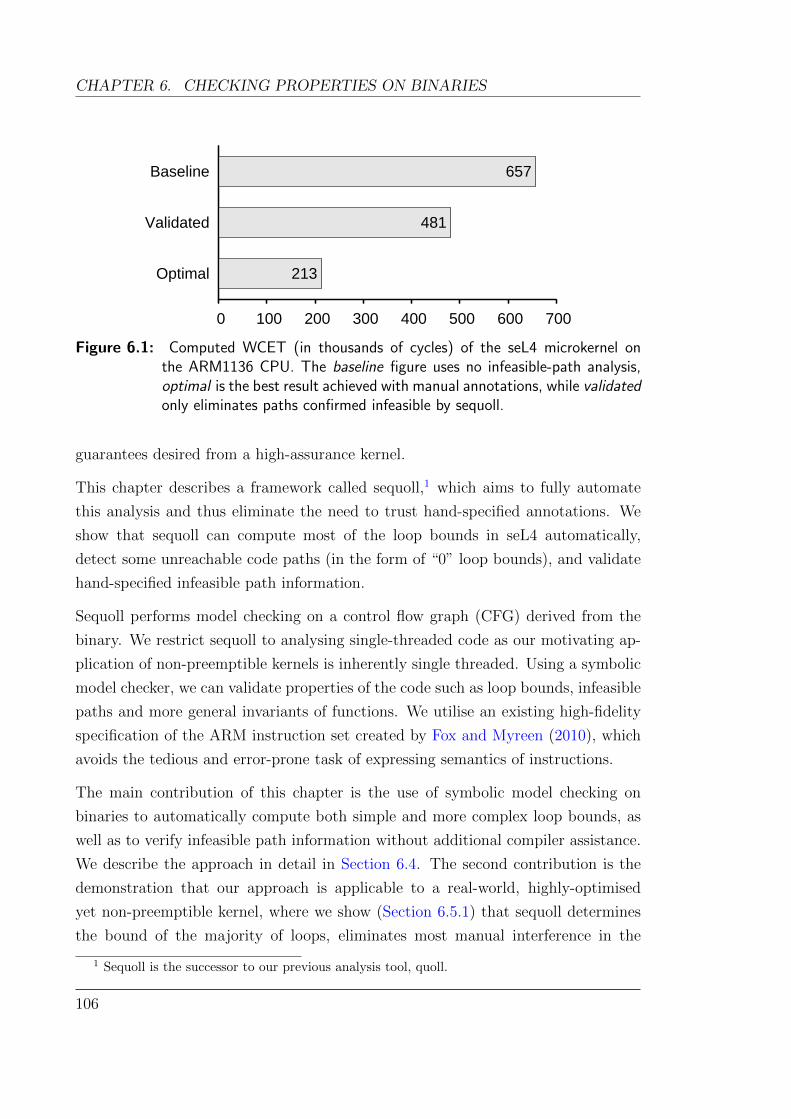
CHAPTER 6. CHECKING PROPERTIES ON BINARIES
Baseline
Validated
Optimal
0 100 200 300 400 500 600 700
657
481
213
Figure 6.1: Computed WCET (in thousands of cycles) of the seL4 microkernel onthe ARM1136 CPU. The baseline figure uses no infeasible-path analysis,optimal is the best result achieved with manual annotations, while validatedonly eliminates paths confirmed infeasible by sequoll.
guarantees desired from a high-assurance kernel.
This chapter describes a framework called sequoll,1 which aims to fully automate
this analysis and thus eliminate the need to trust hand-specified annotations. We
show that sequoll can compute most of the loop bounds in seL4 automatically,
detect some unreachable code paths (in the form of “0” loop bounds), and validate
hand-specified infeasible path information.
Sequoll performs model checking on a control flow graph (CFG) derived from the
binary. We restrict sequoll to analysing single-threaded code as our motivating ap-
plication of non-preemptible kernels is inherently single threaded. Using a symbolic
model checker, we can validate properties of the code such as loop bounds, infeasible
paths and more general invariants of functions. We utilise an existing high-fidelity
specification of the ARM instruction set created by Fox and Myreen (2010), which
avoids the tedious and error-prone task of expressing semantics of instructions.
The main contribution of this chapter is the use of symbolic model checking on
binaries to automatically compute both simple and more complex loop bounds, as
well as to verify infeasible path information without additional compiler assistance.
We describe the approach in detail in Section 6.4. The second contribution is the
demonstration that our approach is applicable to a real-world, highly-optimised
yet non-preemptible kernel, where we show (Section 6.5.1) that sequoll determines
the bound of the majority of loops, eliminates most manual interference in the
1 Sequoll is the successor to our previous analysis tool, quoll.
106

6.2. BACKGROUND
WCET analysis, and improves the WCET estimate of seL4 by 27 % over the baseline
(Figure 6.1). We also evaluate sequoll on the Malardalen WCET benchmark suite
(Gustafsson et al., 2010), and show that it computes 64 % of the loop counts, without
any source-level analysis or manual annotations (Section 6.5.2). We finally discuss
the limitations which currently prevent the remaining loops and annotations from
being analysed (Section 6.6).
6.2 Background
There is a large body of research related to the ideas behind sequoll—computing
loop bounds, modelling instruction set architectures, reasoning about behavioural
guarantees of systems, and reverse-engineering binaries to obtain control flow graphs.
This section highlights the state-of-the-art in each of these areas.
The specific problem of computing loop bounds on binaries has received much at-
tention, particularly from WCET researchers for whom it is a fundamental hurdle.
Manual annotation is a common but error-prone approach, where annotations are
specified at the source code level, and compilers must ensure these annotations are
carried through to the generated assembly (Metzner, 2004). Pattern matching on
the binary can be used to search for common loop structures, but is fragile and
compiler-specific. The aiT WCET analyser uses dataflow analysis to identify loop
variables and loop bounds for simple affine loops in binary programs (Cullmann and
Martin, 2007). Abstract interpretation, polytope modeling and symbolic summation
have also been used to compute loop bounds on high level source code (Lokuciejew-
ski et al., 2009; Blanc et al., 2010). The SWEET toolchain for WCET computation
uses abstract execution to compute loop bounds on binaries, and is aided by tight
integration with the compiler toolchain which improves the knowledge of memory
aliasing (Gustafsson et al., 2006b). The r-TuBound tool uses pattern-based recur-
rence solving and program flow refinement to compute loop bounds, and also requires
tight compiler integration (Knoop et al., 2012).
Rieder et al. (2008) has shown that it is straight-forward to determine loop counts at
the C source-code level through model checking. Attempting to automatically find
a correspondence between source code and its compiled binary, in the presence of
arbitrary compiler optimisations, is a difficult challenge. Although not fully solved
by any single approach (Narasamdya and Voronkov, 2005), significant progress has
107
CHAPTER 6. CHECKING PROPERTIES ON BINARIES
been made recently on finding such a correspondence using an SMT solver (Sewell
et al., 2013).
Model checking is significantly harder to apply to binaries than to source code, as
there is less syntactic information available such as data types and structure layout,
and there is limited information on what memory can potentially alias. Our work has
similarities to Cassez’s methods to compute WCET (2011), but we do not attempt
to compute the overall WCET using a model checker. Although seL4 is a small
microkernel (∼ 8 000 LoC), using model checking for WCET computation does not
(yet) scale to programs of this size.
Eliminating infeasible paths is also crucial for WCET analysis, as such paths may
dramatically worsen the pessimism of WCET estimates. Several techniques have
been proposed to detect infeasible paths, including abstract execution (Gustafsson
et al., 2006b), conflict detection (Suhendra et al., 2006) and pattern matching (Ngo
and Tan, 2007). In the following chapter, we also build upon the sequoll framework
to detect infeasible paths. However, the work presented in this chapter focuses
specifically on the problem of validating manually-specified infeasible paths. This
is computationally less expensive in the general case, whereas many techniques for
detecting infeasible paths do not scale for larger programs.
Model checkers can be used to perform static analysis of high-level languages, with
a number of popular free and commercial tools available. For example, BLAST
performs model checking on C sources using counter-example guided abstraction
refinement (CEGAR) in order to check for desired safety properties (Beyer et al.,
2007). Goanna also uses model checking but tests for common violations, such as
use-after-free bugs (Fehnker et al., 2006).
Closely related to our work is that of Thakur et al. on the McVeto framework
for directed proof generation (Thakur et al., 2010). They use model checking on an
abstraction of arbitrary program binaries to determine if specific target instructions
are reachable. Sequoll instead reasons about paths which may be infeasible in order
to refine WCET analysis.
In addition to model checking, symbolic execution is becoming a popular option for
exploring paths through a program. Symbolic execution groups together all inputs
which may take the same path through a program. This technique is employed by
TRACER (Jaffar et al., 2012) to analyse C code and also by S2E (Chipounov et al.,
2012), a selective symbolic execution platform. These techniques aim to analyse the
108
6.3. THE PROBLEM
properties and behaviour of a program or system under all possible input conditions.
Although symbolic execution would be a suitable alternative for our analysis, we still
chose to write sequoll based upon model checking as we ultimately intend to integrate
invariants based on formal proofs of the code. Model checking supports a more
natural expression of such invariants, and has previously been used in conjunction
with formal proof (Daum et al., 2005).
Conceptually, both loop bounds and infeasible paths could be proven within the
verification of seL4. In practice, seL4’s proofs heavily rely on a functional model
of the code in which “paths” are ill-defined. Termination of the specification is
proven (and must be for the specification to be well-defined), but this does not
require explicit loop bounds. Although proving loop bounds is possible, it is not
immediately useful, as compiler optimisations can (and do) affect these in the binary.
To reconstruct control flow graphs from binaries, various solutions have been pre-
sented and implemented in static analysis frameworks for binaries such as Jakstab
(Kinder and Veith, 2008), BINCOA (Bardin et al., 2011a) and McVeto (Thakur
et al., 2010). These frameworks implement an intermediate assembly language, for
which translators are written for each architecture. To date, none exist for the ARM
architecture.
6.3 The problem
Sequoll was motivated by the desire to validate user-provided annotations about
local code properties which were needed to perform a WCET analysis. Without
independent (and, ideally, automatic) validation, such manual annotations signifi-
cantly weaken the high degree of dependability we expect from the kernel.
Specifically, we seek to (a) automatically compute loop counts, and (b) verify claims
of path infeasibility. We focus on binaries in order to avoid limiting compiler opti-
misations and to remain independent of any specific toolchain.
6.3.1 Loop bounds
The difficulty in determining loop counts in binaries depends heavily on the structure
and invariants on the loops. Compilers may perform optimisations such as loop
109

CHAPTER 6. CHECKING PROPERTIES ON BINARIES
int movs r3, r0
popcount(uint32_t x) moveq r0 , r3
bxeq lr
int c = 0; mov r0, #0
while (x != 0) loop:
if (x & 1) tst r3 , #1
c++; addne r0 , r0 , #1
x = x >> 1; lsrs r3, r3 , #1
bne loop
return c; bx lr
Figure 6.2: A sample C function with no explicit loop variable, and the function com-piled to ARM assembly.
unrolling, rotation or reversal; loop variables may be saved to and restored from
global memory; and loops may not have explicit or obvious loop counters. An
example of this last issue can be seen in the code of Figure 6.2. This function counts
the number of bits which are set in a word. It can be shown that the loop executes
no more than 32 times, despite there being no explicit loop counter. We aim to
compute loop bounds using only knowledge available from the binary.
6.3.2 Infeasible paths
Adding infeasible path information can improve the precision of WCET analyses
considerably. By using knowledge that specific paths are infeasible, seL4’s WCET
estimate can be reduced by 68 %. Previously, we obtained this information by iter-
atively examining the worst-case path reported by our WCET toolchain manually.
If we determined that it was infeasible, we constructed a constraint annotation to
eliminate it. We repeated this until the worst-case path represented a valid execu-
tion.
The infeasible path constraints are used to augment the system of integer linear
equations which is solved to find the WCET. We consider constraints expressed in
one of the following two forms:
• a conflicts with b in f : specifies that the instructions at addresses a and b
are mutually exclusive, and will not both execute during an invocation of the
110

6.4. ANATOMY OF SEQUOLL
ARM formalisation
Symbolic execution, SSA
Simplification, Slicing
Property of Interest
Sequoll
SSA Representation
Symbolic Model
Semantic
Representation
r1_2 <− r3_2 + 4
Model checker
True/False
next(r1_2) := case
011011...
r1 <− r3 + 4
Program Binary
Reduced CFG
Figure 6.3: An overview of the steps performed by sequoll.
function f . If f is invoked multiple times, a and b can each be executed under
different invocations.
• a is consistent with b in f : specifies that the instructions at addresses a and
b will execute the same number of times during an invocation of the function
f .
The process of creating these annotations is error-prone, yet it is a trusted part of
the WCET computation. Being able to validate these annotations will substantially
increase the confidence in the WCET results, improving suitability for critical hard
real-time applications.
6.4 Anatomy of sequoll
The primary inputs to sequoll are a program binary and a property of interest such
as a loop bound or an infeasible path constraint. From this we generate a model
which is tested by a model checker. Figure 6.3 gives an overview of the key steps
111
CHAPTER 6. CHECKING PROPERTIES ON BINARIES
required to produce this model. In this section, we cover the techniques we use in
sequoll to generate a suitable model from the binary.
Our motivation stems from WCET analysis of the seL4 microkernel, whose code
has some restrictions that make verification tractable. We carry some of these
restrictions to sequoll, because they simplify our implementation. In particular, we
assume that program binaries:
• do not contain recursive functions;
• do not contain self-modifying code;
• do not make use of function pointers; and
• are not affected by interrupts, signals, or other asynchronous control flow.
These hold for a large class of programs, particularly critical code running on top of
the real-time OS. For example, the OS shields applications from the visible effects
of interrupts (other than the rate of progress).
We have implemented sequoll in around 10 000 lines of code, excluding external tools
such as the model checker.
6.4.1 Decoding instruction semantics
A prerequisite to performing static analysis on binary code is a representation of the
semantics of instructions. Producing this is typically a complex, error-prone task
and requires careful validation, as any inconsistencies can impact the soundness of
our analysis.
We mitigate these issues and reduce engineering effort by reusing Fox & Myreen’s
formalisation of the ARM instruction set written in the HOL4 theorem prover (2010).
This formalisation has been extensively tested against hardware. It is used in a
number of other projects (Zhao et al., 2011), including within the verification team
at NICTA to prove that a compiled seL4 binary correctly implements the seL4
specification (Sewell et al., 2013).
For a given instruction and system state, it can generate a precise set of semantics.
We handle conditional instructions by adding any conditions to a set of preconditions
112
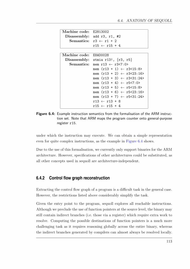
6.4. ANATOMY OF SEQUOLL
Machine code: E2813002
Disassembly: add r3, r1, #2
Semantics: r3 ← r1 + 2
r15 ← r15 + 4
Machine code: E8AD0028
Disassembly: stmia r13!, r3, r5Semantics: mem r13 ← r3<7:0>
mem (r13 + 1) ← r3<15:8>
mem (r13 + 2) ← r3<23:16>
mem (r13 + 3) ← r3<31:24>
mem (r13 + 4) ← r5<7:0>
mem (r13 + 5) ← r5<15:8>
mem (r13 + 6) ← r5<23:16>
mem (r13 + 7) ← r5<31:24>
r13 ← r13 + 8
r15 ← r15 + 4
Figure 6.4: Example instruction semantics from the formalisation of the ARM instruc-tion set. Note that ARM maps the program counter onto general-purposeregister r15.
under which the instruction may execute. We can obtain a simple representation
even for quite complex instructions, as the example in Figure 6.4 shows.
Due to the use of this formalisation, we currently only support binaries for the ARM
architecture. However, specifications of other architectures could be substituted, as
all other concepts used in sequoll are architecture-independent.
6.4.2 Control flow graph reconstruction
Extracting the control flow graph of a program is a difficult task in the general case.
However, the restrictions listed above considerably simplify the task.
Given the entry point to the program, sequoll explores all reachable instructions.
Although we preclude the use of function pointers at the source level, the binary may
still contain indirect branches (i.e. those via a register) which require extra work to
resolve. Computing the possible destinations of function pointers is a much more
challenging task as it requires reasoning globally across the entire binary, whereas
the indirect branches generated by compilers can almost always be resolved locally.
113
CHAPTER 6. CHECKING PROPERTIES ON BINARIES
We use a simple symbolic execution engine to determine the destination of indirect
branches. It performs value analysis and tracks loads and stores into memory. This
allows us to resolve:
• function returns—these typically involve storing the function’s return address
into stack memory and later reading it back either directly into the program
counter, or via another register;
• indirect branches via literal loads—i.e. where the destination address is stored
as data, interspersed within the instruction stream in the binary;
• switch statements—these presently require compiler-specific pattern matching
to decode, as in the general case this is also a difficult problem.
We expand function calls in the control flow graph through virtual inlining. This
is necessary in order to compute loop bounds that are dependent on function argu-
ments or calling context (e.g. in memcpy).
Although this analysis normally works for compiled programs, more sophisticated
compiler optimisations or hand-crafted assembler code can conceivably result in
binaries where our simple symbolic execution engine fails. More comprehensive
analyses exist and these could be implemented and substituted within sequoll if
required (Thakur et al., 2010; Kinder et al., 2009; Bardin et al., 2011b).
Figure 6.5 shows the control-flow graph for our simple example from Figure 6.2.
6.4.3 Loop identification
Given the control flow graph of a program, we can identify loops and classify them
as reducible or irreducible. A reducible loop has a single entry point from outside the
loop body, whereas irreducible loops may have multiple entry points (Tarjan, 1974).
Irreducible loops are problematic for any WCET analysis that relies on specifying
loop bounds relative to a unique entry point. They also lead to ambiguity in program
structure, such as the relationship between nested loops (Havlak, 1997).
We currently restrict sequoll to analysing reducible loops and failing when an ir-
reducible loop is encountered. If required, irreducible loops could be handled by
duplicating them in the CFG—once for each entry edge. We have not done this in
sequoll as it adds unnecessary complexity for our use cases.
114
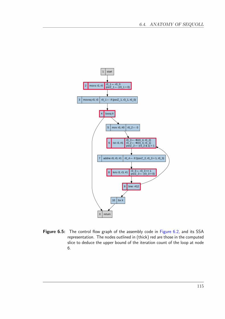
6.4. ANATOMY OF SEQUOLL
1 start
2 movs r3, r0 r3_1 ← r0_0psrZ_1 ← (r3_1 = 0)
3 moveq r0, r3 r0_1 ← if (psrZ_1, r3_1, r0_0)
4 bxeq lr
0 return
5 mov r0, #0 r0_2 ← 0
6 tst r3, #1r0_3 ← Φ(r0_4, r0_2)r3_2 ← Φ(r3_3, r3_1)psrZ_2 ← (r3_2 & 1) = 1
7 addne r0, r0, #1 r0_4 ← if (!psrZ_2, r0_3 + 1, r0_3)
8 lsrs r3, r3, #1 r3_3 ← r3_3 << 1psrZ_3 ← (r3_3 = 0)
9 bne -#12
10 bx lr
Figure 6.5: The control flow graph of the assembly code in Figure 6.2, and its SSArepresentation. The nodes outlined in (thick) red are those in the computedslice to deduce the upper bound of the iteration count of the loop at node6.
115
CHAPTER 6. CHECKING PROPERTIES ON BINARIES
Given a node E as a possible candidate for a loop entry point, we define a loop
as the largest strongly connected component (SCC) that includes E, such that E
dominates all other nodes within the loop. If no such SCC exists, then E does not
induce a loop. This gives a one-to-one relationship between entry points and loops
(under the reducibility criterion).
Sequoll finds reducible loops via a depth-first search, identifying for every instruction
its inner-most loop, and reconstructing the loop nests of the program.
6.4.4 SSA transformation
We convert the program to single static assignment (SSA) form, as this simplifies
later stages of our analysis. A program in SSA form has the property that each
variable is assigned to at most once. Using SSA makes it much simpler to track
the dependencies between variables. Where program paths merge with potentially
different values for a variable, a special function known as a φ (“phi”) function is
used to represent the choice of values based on path.
The primary advantage of using SSA representation is that it can greatly reduce
the number of states required for model-checking; we describe this further in Sec-
tion 6.4.7. We use standard techniques to convert the program’s representation into
SSA form (Cytron et al., 1991).
Figure 6.5 shows the SSA representation of our example from Figure 6.2 (with the
irrelevant portions elided). Multiple edges reach node 6 in this diagram, and hence
φ functions define the values of r0 and r3.
6.4.5 Simplification
Once transformed to SSA form, there are many opportunities to simplify expres-
sions within the analysis. For example, a program increments and decrements the
stack pointer as it pushes or pops data on and off the stack. As Figure 6.6 shows,
constant propagation often allows us to condense these chains of arithmetic to a
simple expression, specifying the offset against the original stack pointer.
The φ functions generated by SSA transformation can also be simplified if all possible
values are equivalent. This is particularly pertinent for the stack pointer, which
generates a significant number of φ functions as its value is frequently modified.
116
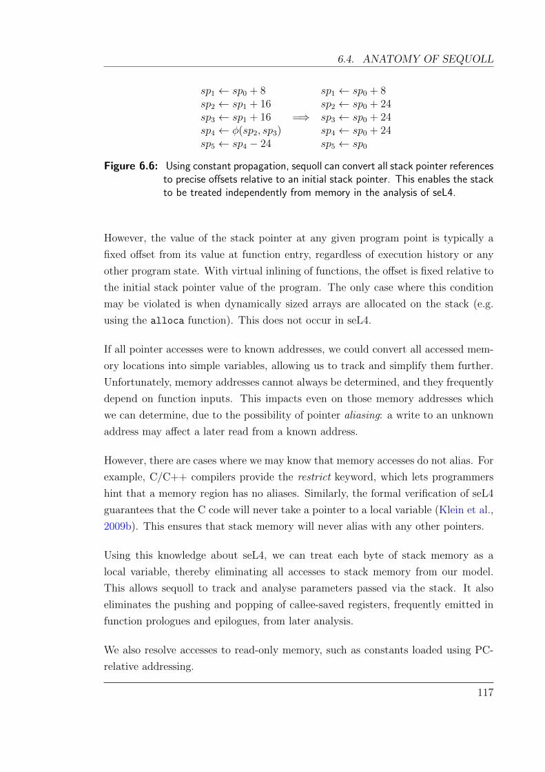
6.4. ANATOMY OF SEQUOLL
sp1 ← sp0 + 8 sp1 ← sp0 + 8sp2 ← sp1 + 16 sp2 ← sp0 + 24sp3 ← sp1 + 16 =⇒ sp3 ← sp0 + 24sp4 ← φ(sp2, sp3) sp4 ← sp0 + 24sp5 ← sp4 − 24 sp5 ← sp0
Figure 6.6: Using constant propagation, sequoll can convert all stack pointer referencesto precise offsets relative to an initial stack pointer. This enables the stackto be treated independently from memory in the analysis of seL4.
However, the value of the stack pointer at any given program point is typically a
fixed offset from its value at function entry, regardless of execution history or any
other program state. With virtual inlining of functions, the offset is fixed relative to
the initial stack pointer value of the program. The only case where this condition
may be violated is when dynamically sized arrays are allocated on the stack (e.g.
using the alloca function). This does not occur in seL4.
If all pointer accesses were to known addresses, we could convert all accessed mem-
ory locations into simple variables, allowing us to track and simplify them further.
Unfortunately, memory addresses cannot always be determined, and they frequently
depend on function inputs. This impacts even on those memory addresses which
we can determine, due to the possibility of pointer aliasing: a write to an unknown
address may affect a later read from a known address.
However, there are cases where we may know that memory accesses do not alias. For
example, C/C++ compilers provide the restrict keyword, which lets programmers
hint that a memory region has no aliases. Similarly, the formal verification of seL4
guarantees that the C code will never take a pointer to a local variable (Klein et al.,
2009b). This ensures that stack memory will never alias with any other pointers.
Using this knowledge about seL4, we can treat each byte of stack memory as a
local variable, thereby eliminating all accesses to stack memory from our model.
This allows sequoll to track and analyse parameters passed via the stack. It also
eliminates the pushing and popping of callee-saved registers, frequently emitted in
function prologues and epilogues, from later analysis.
We also resolve accesses to read-only memory, such as constants loaded using PC-
relative addressing.
117
CHAPTER 6. CHECKING PROPERTIES ON BINARIES
6.4.6 Program slicing
Often, the property we wish to check involves a small portion of the entire pro-
gram. We can speed up the analysis significantly by computing a smaller, equivalent
program which preserves the property of interest, precisely what the technique of
program slicing achieves (Weiser, 1984). Given a property of interest, known as the
slice criterion, we recursively follow all data-flow and control-flow dependencies to
compute an equivalent program with respect to this property.
We select the slice criteria based on the variables or control flow nodes relevant to
our desired property. For instance, to compute loop bounds, we count the maximum
number of times that the head of a loop may execute. Here the slice criterion simply
consists of the loop head node (containing the first instruction in the loop). The
slicing algorithm will begin by finding the control-flow dependencies for the loop
head. This will include any conditional statements outside the loop which may
prevent its execution, as well as any nodes inside the loop which may conditionally
exit it.
It is possible that we over-approximate the slice, however it is guaranteed to be
equivalent with regard to the slice criteria. Slices that are too large can make model
checking prohibitively expensive. The simplification step described in Section 6.4.5
helps to minimise the size of the slice.
Some loops are bounded only because of earlier conditions on the path leading to
them. Consider the code below—the loop is only bounded because it does not
execute if the preceding condition fails. The slicing algorithm will identify the
relevant parts of the execution history and preserve those in the slice.
if (c < 100)
for (i = 0; i < c; i++)
...
The trail of dependencies leading up to the head of the loop can be quite long,
with much of it irrelevant for a tight bound. Consider a loop with two possible
exit conditions—one exits the loop when an iteration count variable exceeds a hard-
coded upper bound, while a second tests the iteration count variable against a
complex expression computed before the loop. If we only care about the hard-coded
118
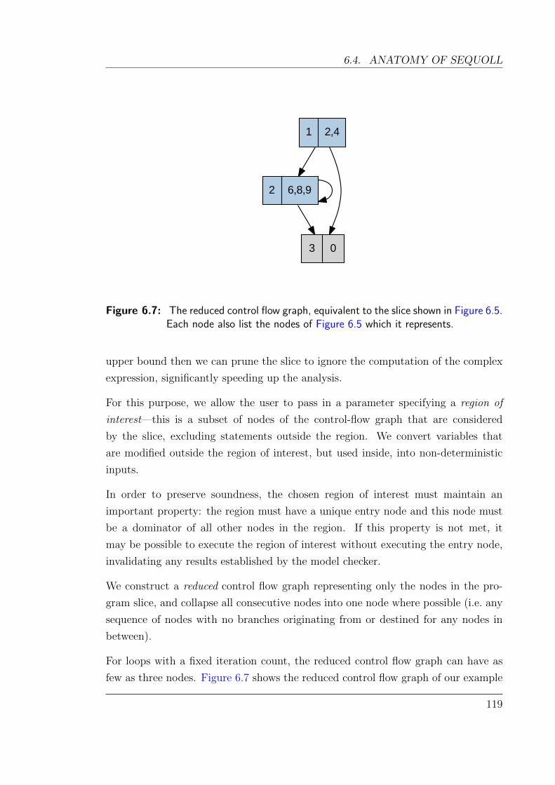
6.4. ANATOMY OF SEQUOLL
1 2,4
2 6,8,9
3 0
Figure 6.7: The reduced control flow graph, equivalent to the slice shown in Figure 6.5.Each node also list the nodes of Figure 6.5 which it represents.
upper bound then we can prune the slice to ignore the computation of the complex
expression, significantly speeding up the analysis.
For this purpose, we allow the user to pass in a parameter specifying a region of
interest—this is a subset of nodes of the control-flow graph that are considered
by the slice, excluding statements outside the region. We convert variables that
are modified outside the region of interest, but used inside, into non-deterministic
inputs.
In order to preserve soundness, the chosen region of interest must maintain an
important property: the region must have a unique entry node and this node must
be a dominator of all other nodes in the region. If this property is not met, it
may be possible to execute the region of interest without executing the entry node,
invalidating any results established by the model checker.
We construct a reduced control flow graph representing only the nodes in the pro-
gram slice, and collapse all consecutive nodes into one node where possible (i.e. any
sequence of nodes with no branches originating from or destined for any nodes in
between).
For loops with a fixed iteration count, the reduced control flow graph can have as
few as three nodes. Figure 6.7 shows the reduced control flow graph of our example
119
CHAPTER 6. CHECKING PROPERTIES ON BINARIES
code from Figure 6.2; in this case, 11 nodes were reduced to three. More complex
loop structures will obviously introduce more nodes, but our evaluation (Table 6.1)
shows that in most cases the graph remains very small.
6.4.7 Translation to a symbolic model
The final step in processing the binary is to convert the reduced graph of our program
slice into a symbolic model, which can be checked by a model checker. We use the
NuSMV model checker (Cimatti et al., 2002) which supports assertions expressed
in temporal logic such as linear temporal logic (LTL) or computational tree logic
(CTL). These logics are able to express useful properties such as “the value of
some variable is always less than k” or “state A is not reachable until state B has
occurred”.
We convert variables in our SSA representation into one of three types of expressions
in the model:
• stateful variables: these variables are updated by transitions in the model and
contribute to the state space which the model checker must explore;
• frozen variables: these variables retain their value throughout the program,
and also contribute to the state space which must be explored; and
• definitions: these incur no state of themselves (much like C preprocessor
macros), and act merely as syntactic sugar for building larger models.
We translate the variables of the reduced control flow graph into a symbolic model
as follows:
• Variables that are used but not defined anywhere in the SSA representation
are inputs to the program. These are converted to frozen variables.
• Both φ functions and memory reads are converted to stateful variables in the
model.
• All other SSA variables become definitions, as they themselves do not need to
incur any state in the model.
120

6.4. ANATOMY OF SEQUOLL
The key observation here is that there are only two cases in which the program’s
execution may diverge, requiring the model checker to explore multiple states. The
first is at memory reads when the result is unknown, either due to potential aliasing
or otherwise being unable to identify a corresponding memory store.
The second case is when multiple paths can be taken through the control flow graph.
Perhaps somewhat unintuitively, we only need to consider points where program
paths converge rather than diverge. Given a node with multiple incoming edges, the
choice of incoming edge implicitly defines which outgoing edges were taken earlier in
the execution. This fits naturally with the SSA representation of φ functions which
assign variables only at converging nodes.
For the example in Figure 6.5, we only need to create a single stateful variable for
the expression r3 2← φ(r3 3, r3 1). This is defined in the model checker as follows:
next(r3_2) := case
n=1: r3_1;
n=2: r3_3;
TRUE: r3_2;
esac;
This intuitive syntax states that when visiting node 1 (in the reduced control flow
graph of Figure 6.7), r3 1 should be assigned to r3 2; similarly at node 2, r3 3
should be assigned. The variable retains its value at all other nodes.
The input variable r0 0 is specified as a frozen variable. All other information
needed for the program slice is specified as definitions which incur no additional
state.
psrZ_3 := r3_3 = 0;
psrZ_1 := r3_1 = 0;
r3_3 := r3_2 >> 1;
r3_1 := r0_0;
In addition to the SSA variables, we represent the reduced control flow graph of the
program slice as an additional stateful variable. The transitions between nodes are
represented in the model by conditional assignments to this stateful variable. For
example, the reduced control flow graph in Figure 6.7 becomes:
121
CHAPTER 6. CHECKING PROPERTIES ON BINARIES
init(n) := 1;
next(n) := case
n=1 & !psrZ_1: 2;
n=1 & psrZ_1: 3;
n=2 & !psrZ_3: 2;
n=2 & psrZ_3: 3;
n=3: 3;
esac;
6.4.8 Loop bound checking
To solve the example loop bound from Figure 6.2, we assign a stateful variable
C in the model checker which counts the number of times the loop entry node
executes. The variable is reset to zero at nodes outside the loop that are immediate
predecessors of the loop entry node.
Although the model checker cannot directly compute the loop bound for us, we can
ask the model checker a statement of the form “is C ≤ k?”. We can then perform
a binary search to find the smallest value of k for which the statement holds true.
This value is the maximum number of times that the loop may iterate.
6.4.9 Path feasibility testing
As described in Section 6.3.2, we express the path infeasibility constraints in terms
of pairs of instructions which either conflict with each other (are mutually exclusive),
or are consistent with each other (both execute the same number of times).
These constraints translate naturally to expressions suitable for model checking,
as follows. For conflict constraints, we create boolean flags a and b for the two
instructions of interest. These flags are set to true when the respective node is
visited. We can then express the infeasibility condition as the assertion that a
and b are never simultaneously true. For consistency constraints, we use execution
counters instead of flags, and assert that all paths finish with both counters equal.
122

6.5. EVALUATION
6.5 Evaluation
6.5.1 seL4
Our primary motivation for developing sequoll was to validate annotations on our
timing analysis of the seL4 microkernel, hence this is the obvious test case.
We use sequoll to automatically compute the loop bounds on all loops within the
seL4 binary, which contains 32 loops in 11 functions. Regions of interest were spec-
ified on many of these loops—in particular, loops where there were exit conditions
with long chains of data dependencies that have no effect on the worst-case itera-
tion count. Sequoll succeeds in computing precise bounds on 18 loops (56 %). The
analysis on the remaining loops presently fails for one of several reasons, which we
discuss in detail in Section 6.6:
• one loop is only bounded thanks to an invariant maintained by its environ-
ment ;
• one loop sequoll cannot analyse due to complex exit conditions ;
• on 12 loops, all of identical structure, sequoll fails to determine a bound due
to poor memory aliasing analysis ;
Of the 18 loops, 13 loop bounds are computed within 10 seconds each, three further
loops within one minute, and two more complex bounds in 28 minutes—99% of
which is spent performing SSA transformation and simplification. This step is slow
primarily because of the expensive live variable analysis on the inlined control flow
graph, which consists of over one million nodes. The analysis of seL4 used at most
6 GiB of memory.
Our best (manual) analysis eliminated 35 infeasible paths by manually adding appro-
priate constraint annotations, reducing the computed WCET bound from 657 000
cycles to 213 000 cycles, a 67 % improvement. Of these, sequoll validated 4, which
was sufficient to reduce the bound to 481 000 cycles (a 26 % improvement), see Fig-
ure 6.1.
One of our manual constraints turned out to be wrong, as we found through sequoll!
Fortunately, this somewhat embarrassing fact had no effect on the WCET estimate,
123
CHAPTER 6. CHECKING PROPERTIES ON BINARIES
but serves as a clear warning about the fickle nature of annotations derived from
path inspections.
Of the remaining 30 constraints,
• 11 relate to infeasible paths which depend on values read from memory that
can potentially alias. The loss of information makes it impossible to determine
if these paths are truly infeasible.
• 19 depend on invariants which are not possible to ascertain from the binary.
6.5.2 WCET benchmarks
We use the Malardalen WCET benchmark suite (Gustafsson et al., 2010) to fur-
ther evaluate sequoll’s ability to deduce loop bounds. We compile the C sources
for the ARMv6 architecture, using gcc 4.4.1 and the -O2 optimisation level. We
omit benchmarks using floating-point arithmetic, as the ARM formalisation does
not presently support the instructions used for hardware floating point (Fox and
Myreen, 2010). We also omit the recursion benchmark, as our analysis does not
presently support recursive functions. Finally, we do not analyse two programs
containing irreducible (multiple-entry) loops, as “iteration count” is ill-defined on
these structures. However, this does not preclude them from being checked for other
properties.
Table 6.1 presents the results. Because of the compiler’s aggressive optimisation,
loops present in the C code were sometimes partially unrolled, completely unrolled
or occasionally duplicated. Hence, the total number of loops listed in Table 6.1
differs in many cases from those evident in the C code.
The benchmark binaries we analysed have a total of 66 loops. Of these, sequoll
computed the bounds of 41 automatically (62 %). Sequoll could compute the bound
of one further loop (in expint) after specifying a region of interest, as described in
Section 6.4.6.
Analysis of the remaining 24 loops fails for a number of reasons. We assume failure
when the model checker either exhausts system memory or shows no signs of progress
within 12 hours. Note that some loops fail for multiple causes, and we count those
under each cause:
124
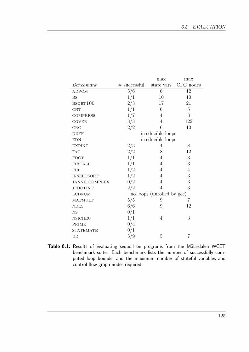
6.5. EVALUATION
max maxBenchmark # successful state vars CFG nodesadpcm 5/6 6 12bs 1/1 10 10bsort100 2/3 17 21cnt 1/1 6 5compress 1/7 4 3cover 3/3 4 122crc 2/2 6 10duff irreducible loopsedn irreducible loopsexpint 2/3 4 8fac 2/2 8 12fdct 1/1 4 3fibcall 1/1 4 3fir 1/2 4 4insertsort 1/2 4 3janne complex 0/2 4 3jfdctint 2/2 4 3lcdnum no loops (unrolled by gcc)matmult 5/5 9 7ndes 6/6 9 12ns 0/1nsicheu 1/1 4 3prime 0/4statemate 0/1ud 5/9 5 7
Table 6.1: Results of evaluating sequoll on programs from the Malardalen WCETbenchmark suite. Each benchmark lists the number of successfully com-puted loop bounds, and the maximum number of stateful variables andcontrol flow graph nodes required.
125
CHAPTER 6. CHECKING PROPERTIES ON BINARIES
• Memory accesses: 9 failures are due to loop bounds subject to memory aliasing,
as discussed above.
• Complex early exits: 7 loops clearly have fixed upper bounds, but can exit early
in certain cases. The conditions for early exit depend on complex expressions,
such as tests for divisibility in the prime benchmark. These expressions gen-
erate dozens of stateful variables, preventing the model checker from solving
them in a timely fashion.
• Complex loop bounds: 8 loops have bounds which are complex expressions.
Most of these are inner loops, where the state of the outer loop determines
the iteration count. Our model checker fails to determine these loop bounds
within several hours.
• Software division: 6 loops fail because their loop bounds depend on the result
of an integer division—on our ARM platform, integer division is emulated in
software, and the routines are far too complex for our model checker.
Analysis time: 28 of the 41 loops are computed by the model checker within five
seconds each, and 39 within one minute. Two computations take significantly longer
to run: analysis of one loop in bsort100 takes 14 minutes, and one loop in adpcm
requires 9 hours. Both of these cases are due to a loop exit condition which requires
the model checker to explore the state space across two nested loops simultaneously.
The loop in adpcm also has an upper bound of 999—the largest of any of our
benchmark results.
As the loop bounds increase, the model checker requires more time to explore the
state space, and the binary search for the loop bound requires more iterations. Thus,
in general, smaller loop bounds will inherently be faster to compute.
Note that these durations do not include the time required by the ARM formalisation
to generate the instruction semantics. This step is particularly slow in its current
version, taking around one second per instruction. We mitigate this by caching the
instructions as they are generated so that subsequent analyses of the same binary
are much faster.
The analysis phase of sequoll used at most 300 MiB of memory for all benchmarks,
whilst the NuSMV model checker consumed up to 1.5 GiB.
126
6.6. DISCUSSION
6.6 Discussion
While the results so far are encouraging, we would ideally like to automate all loop
analysis. Here we take a closer look at what we can do to improve the success rate.
• Potentially aliasing memory accesses affect loops and infeasible paths fairly
frequently. In the problematic loops, the binary computes the upper bound
and stores it into memory, where it vanishes from the view of our analysis.
Improved alias analysis may resolve this and result in the automatic compu-
tation of the bounds of all affected loops (12 in seL4 and 11 in the WCET
benchmarks). Applied to infeasible path detection on seL4, this alone would
improve the WCET estimate from 27 % to 54 % over the baseline. Techniques
such as those developed for McVeto (Thakur et al., 2010) are appropriate
candidates, as they can be used to identify aliasing conditions relevant to
specific properties of interest, and operate on compiled binaries.
• Complex early exits within single loop nests we could handle by considering
each exit edge individually—the lowest result of any successfully analysed exit
edge can be used as a safe upper bound. This works in single loop nests, as
following any exit edge precludes the loop from iterating further. It is also
suitable for simple inner loops where there are no dependencies on variables
defined by outer loops, as the iteration count of an inner loop can be computed
without regard to outer loop iterations. However, it is unsound for inner loops
with dependencies on the outer loops, as the exit edge taken may vary with
each execution of the loop.
• Complex loop bounds may be out of reach of model checkers for now, notwith-
standing advances in model checking technology. Other techniques such as
symbolic execution may be more appropriate to solve these.
• We could deal with software division by catching calls to the software emu-
lation routines and replacing them with the model checker’s native division
operator.
• Loop bounds and infeasible paths which depend on invariants maintained in
the code’s environment cannot be computed by local static analysis. A good
example of this (from seL4) is equivalent to the following C code:
127
CHAPTER 6. CHECKING PROPERTIES ON BINARIES
uint32_t i = 1 << b;
if (i > 256)
i = 256;
while (i != 0)
/* ... */
i -= 4;
Although there appears to be a loop variable with an upper bound, there exist
values of the input b for which this loop will never terminate (b ≤ 1 or b ≥ 32).
An invariant from the seL4 proof states that b is always in the range [4, 31].
Thus the loop is safe in its context of use, but our analysis tool is unable to
deduce this fact. In fact, any sound method of detecting infeasible paths could
not discover this without effectively reproducing a substantial part of the seL4
proof.
In principle we can address such cases by importing invariants from the formal
verification of the kernel into sequoll. Using such information is an interesting
challenge for future research. On top of what is achievable by alias analysis,
this would achieve a near-optimal WCET (68 % better than baseline) with a
very strong level of confidence.
Finally we observe that there are very few infeasible paths in the Malardalen bench-
marks, as these are mostly single-path programs. However, sequoll in fact detected
some infeasible paths as loops with an iteration count of 0 (due to virtual inlining,
some loops became unreachable).
6.7 Summary
We have presented sequoll, a framework for verifying local properties of binaries such
as loop counts and path infeasibility information. Using symbolic model checking on
program binaries can avoid a major source of human error, and in turn strengthens
the assurances on a WCET analysis.
We evaluated sequoll on the seL4 microkernel, a challenging target due to its non-
preemptible design, resulting in long code paths to be analysed. We were able to
automatically compute the majority of loops and found that almost all failures could
128

6.7. SUMMARY
be avoided by the use of a more sophisticated memory aliasing analysis. We also
validated several of the infeasible path constraints, gaining a 27 % improvement in
WCET, without trusting any user annotations.
We also used the Malardalen benchmark suite, where sequoll computes 64 % of
the loop bounds from the binary alone, alias analysis being again the dominating
limitation. However, some issues still remain on complex loops.
The speed of the ARM formalisation is problematic for larger programs, contribut-
ing to the majority of the computation time (although its results can be cached).
Future versions of the ARM formalisation aim to improve its speed, however the
construction within an LCF-style theorem prover inherently limits its performance.
Work is under way to formalise the ARMv7 instruction set using a domain-specific
language, which can be retargeted for different environments such as theorem provers
and other analysis tools (Fox, 2012). Once this work comes to fruition, we can easily
substitute the results into sequoll, or indeed any other formalisation.
Opportunities for future research directions include eliminating further sources of
human error, improving memory alias analysis, and incorporating formally-proven
invariants of the source code into the model. In the following chapter, we build upon
the framework of sequoll and extend it to automatically detect infeasible paths.
129

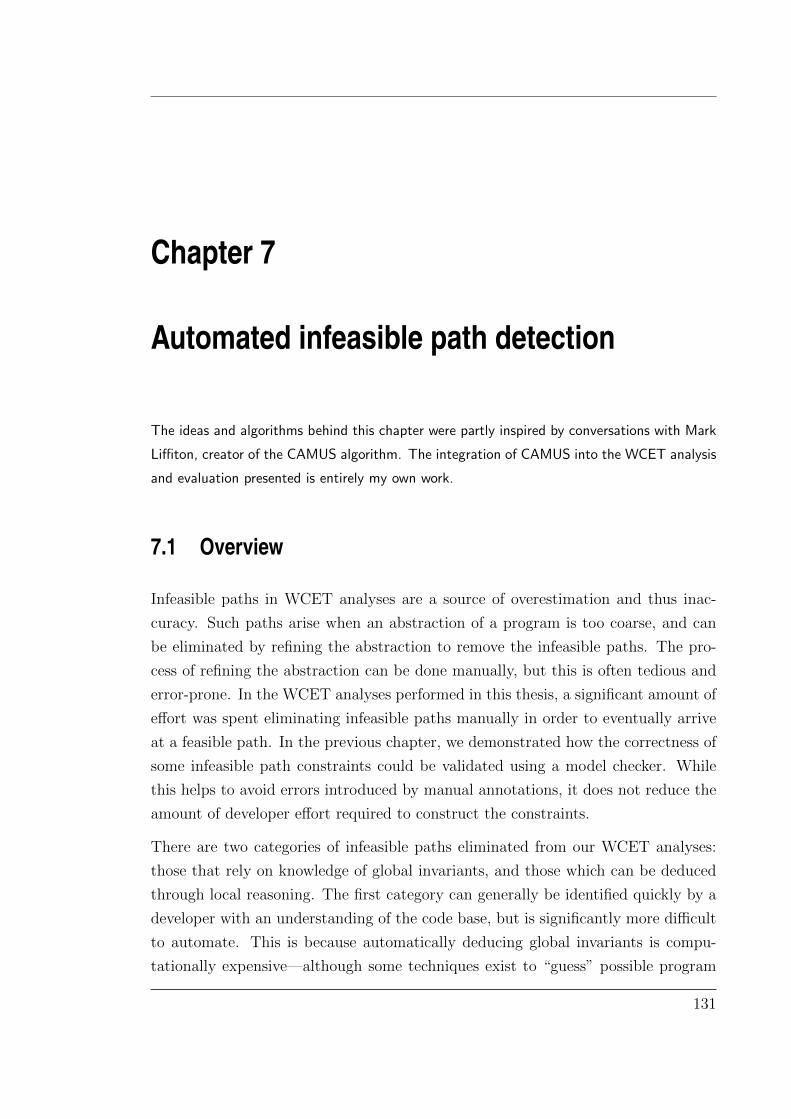
Chapter 7
Automated infeasible path detection
The ideas and algorithms behind this chapter were partly inspired by conversations with Mark
Liffiton, creator of the CAMUS algorithm. The integration of CAMUS into the WCET analysis
and evaluation presented is entirely my own work.
7.1 Overview
Infeasible paths in WCET analyses are a source of overestimation and thus inac-
curacy. Such paths arise when an abstraction of a program is too coarse, and can
be eliminated by refining the abstraction to remove the infeasible paths. The pro-
cess of refining the abstraction can be done manually, but this is often tedious and
error-prone. In the WCET analyses performed in this thesis, a significant amount of
effort was spent eliminating infeasible paths manually in order to eventually arrive
at a feasible path. In the previous chapter, we demonstrated how the correctness of
some infeasible path constraints could be validated using a model checker. While
this helps to avoid errors introduced by manual annotations, it does not reduce the
amount of developer effort required to construct the constraints.
There are two categories of infeasible paths eliminated from our WCET analyses:
those that rely on knowledge of global invariants, and those which can be deduced
through local reasoning. The first category can generally be identified quickly by a
developer with an understanding of the code base, but is significantly more difficult
to automate. This is because automatically deducing global invariants is compu-
tationally expensive—although some techniques exist to “guess” possible program
131
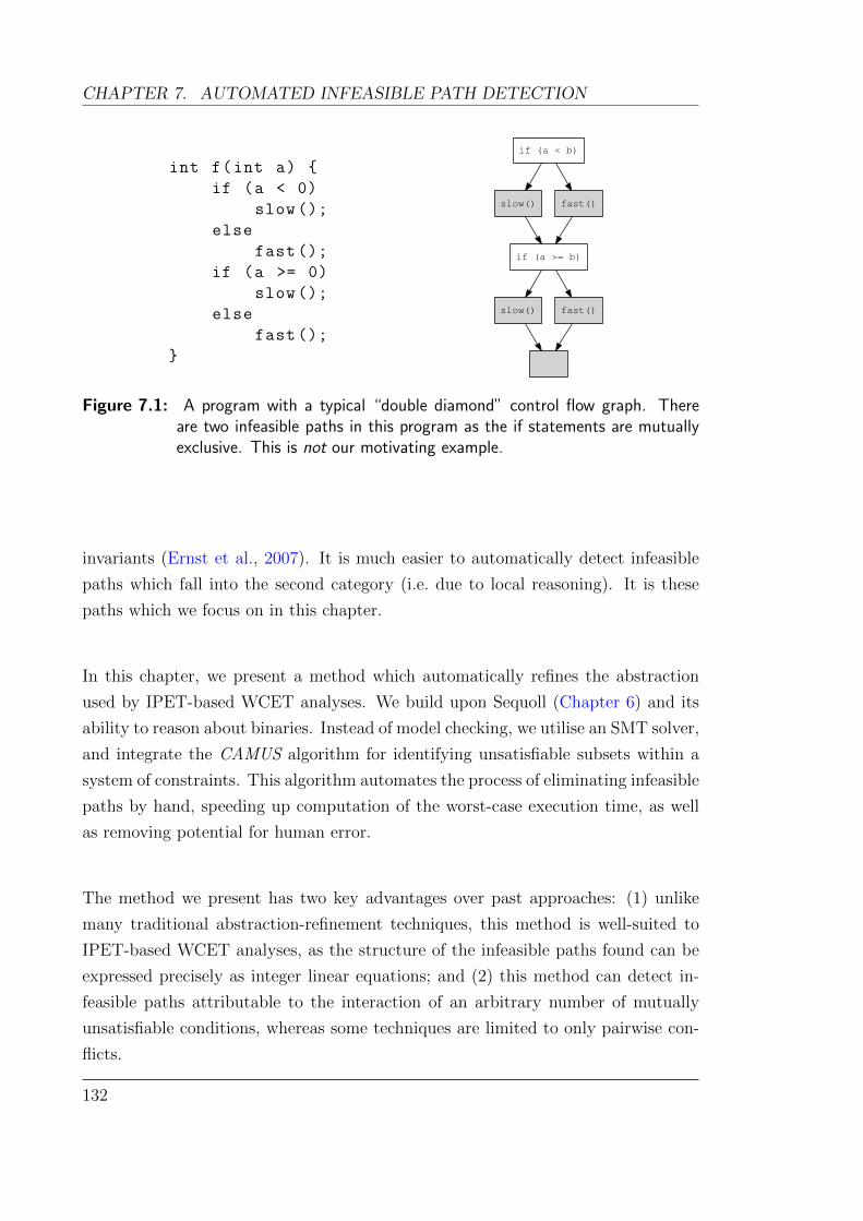
CHAPTER 7. AUTOMATED INFEASIBLE PATH DETECTION
int f(int a)
if (a < 0)
slow ();
else
fast ();
if (a >= 0)
slow ();
else
fast ();
if (a < b)
slow() fast()
if (a >= b)
slow() fast()
Figure 7.1: A program with a typical “double diamond” control flow graph. Thereare two infeasible paths in this program as the if statements are mutuallyexclusive. This is not our motivating example.
invariants (Ernst et al., 2007). It is much easier to automatically detect infeasible
paths which fall into the second category (i.e. due to local reasoning). It is these
paths which we focus on in this chapter.
In this chapter, we present a method which automatically refines the abstraction
used by IPET-based WCET analyses. We build upon Sequoll (Chapter 6) and its
ability to reason about binaries. Instead of model checking, we utilise an SMT solver,
and integrate the CAMUS algorithm for identifying unsatisfiable subsets within a
system of constraints. This algorithm automates the process of eliminating infeasible
paths by hand, speeding up computation of the worst-case execution time, as well
as removing potential for human error.
The method we present has two key advantages over past approaches: (1) unlike
many traditional abstraction-refinement techniques, this method is well-suited to
IPET-based WCET analyses, as the structure of the infeasible paths found can be
expressed precisely as integer linear equations; and (2) this method can detect in-
feasible paths attributable to the interaction of an arbitrary number of mutually
unsatisfiable conditions, whereas some techniques are limited to only pairwise con-
flicts.
132
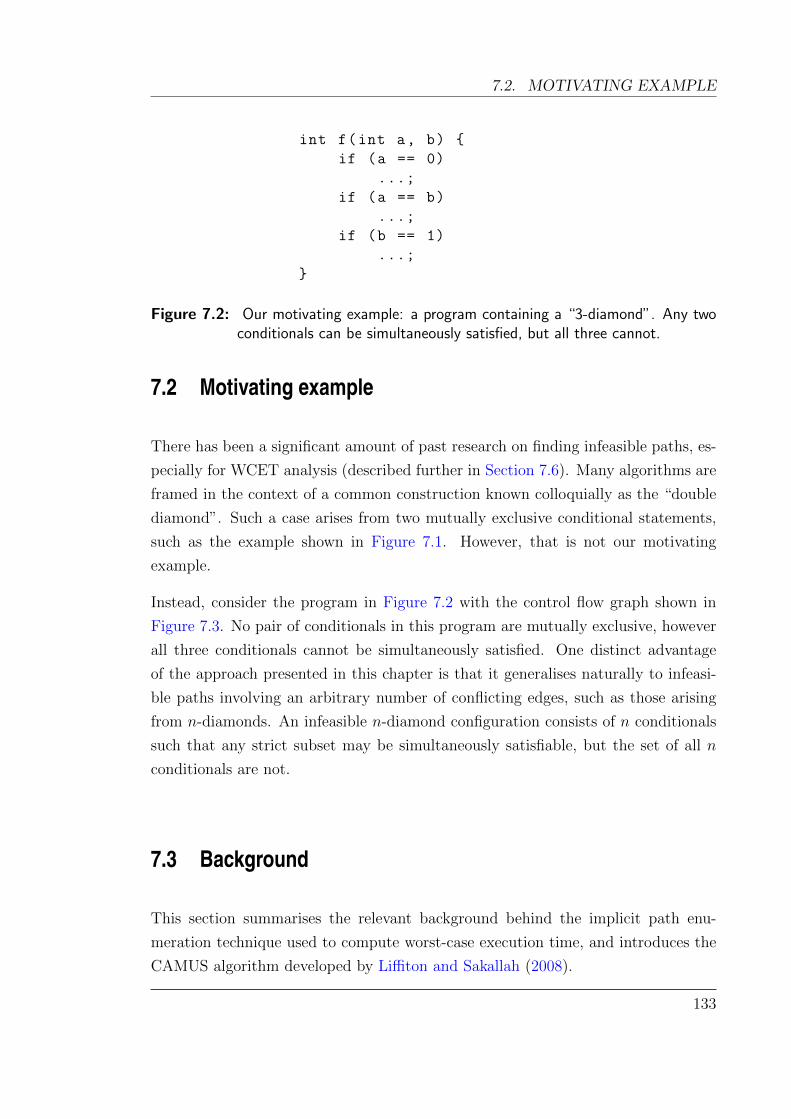
7.2. MOTIVATING EXAMPLE
int f(int a, b)
if (a == 0)
...;
if (a == b)
...;
if (b == 1)
...;
Figure 7.2: Our motivating example: a program containing a “3-diamond”. Any twoconditionals can be simultaneously satisfied, but all three cannot.
7.2 Motivating example
There has been a significant amount of past research on finding infeasible paths, es-
pecially for WCET analysis (described further in Section 7.6). Many algorithms are
framed in the context of a common construction known colloquially as the “double
diamond”. Such a case arises from two mutually exclusive conditional statements,
such as the example shown in Figure 7.1. However, that is not our motivating
example.
Instead, consider the program in Figure 7.2 with the control flow graph shown in
Figure 7.3. No pair of conditionals in this program are mutually exclusive, however
all three conditionals cannot be simultaneously satisfied. One distinct advantage
of the approach presented in this chapter is that it generalises naturally to infeasi-
ble paths involving an arbitrary number of conflicting edges, such as those arising
from n-diamonds. An infeasible n-diamond configuration consists of n conditionals
such that any strict subset may be simultaneously satisfiable, but the set of all n
conditionals are not.
7.3 Background
This section summarises the relevant background behind the implicit path enu-
meration technique used to compute worst-case execution time, and introduces the
CAMUS algorithm developed by Liffiton and Sakallah (2008).
133
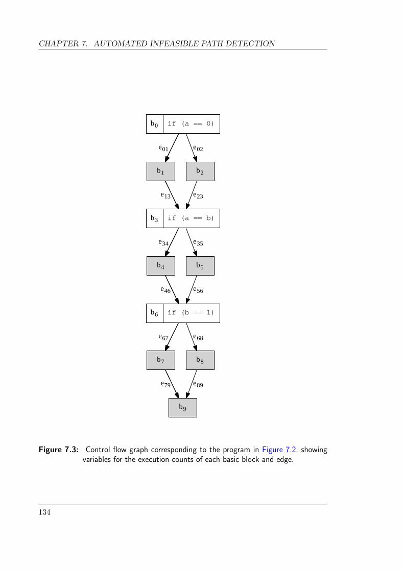
CHAPTER 7. AUTOMATED INFEASIBLE PATH DETECTION
b0 if (a == 0)
b1
e01
b2
e02
b3 if (a == b)
e13 e23
b4
e34
b5
e35
b6 if (b == 1)
e46 e56
b7
e67
b8
e68
b9
e79 e89
Figure 7.3: Control flow graph corresponding to the program in Figure 7.2, showingvariables for the execution counts of each basic block and edge.
134

7.3. BACKGROUND
7.3.1 WCET computation by IPET
As described in Section 2.4.1, there are many approaches to computing the worst-
case execution time of a program, each with their own advantages and drawbacks.
Computing precise WCET on large programs executing on modern CPU architec-
tures requires using abstractions of the program and/or CPU. The choice of abstrac-
tion selects a compromise between accuracy and scalability. Here, we only focus on
refining the program abstraction, not the CPU.
We use the implicit path enumeration technique pioneered by Li et al. (1995) and
implemented in Chronos (Li et al., 2007). Recall from Section 2.4.2 that IPET
computes the WCET by viewing it as a linear optimisation problem. It formulates
a set of integer linear equations where variables are used to represent the execution
counts of each basic blocks, as well as each edge between blocks. The flow constraints
from the control flow graph of the program are encoded as linear equations in an
integer linear programming problem, as are the constraints on loop bounds.
In its primitive construction, the equations encode only the structure of the control
flow graph and ignore the flow of any data through the program. It is entirely pos-
sible for a worst-case path found in this construction to be infeasible in practice, for
example, because of conditional branches that cannot be satisfied. If the constraints
which cause a path to be infeasible can be expressed as a linear equation, then we
can add the equation to the ILP problem to exclude it. Note that not all infeasible
paths can be expressed this way—for example, any constraint involving non-linear
arithmetic.
In the remainder of this chapter, we use bi to both identify the basic block, and
as a variable denoting the execution count when part of an equation. Similarly eij
identifies the edge from bi to bj, as well the variable denoting the number of times
that edge is taken.
Given our example in Figure 7.3, we can express the fact that all three conditionals
are mutually unsatisfiable by the following equation:
e01 + e34 + e67 ≤ 2
This equation states that the sum of execution counts of the three “true” edges in
the CFG is at most two, therefore no path will take all three edges. Note that this
expression is only correct if this fragment of the control flow graph only executes
135

CHAPTER 7. AUTOMATED INFEASIBLE PATH DETECTION
once (i.e. if it is not part of a loop). We address loops in Section 7.4.
7.3.2 Computing all minimal unsatisfiable subsets
Satisfiability Modulo Theories (SMT) solvers can be used to determine if a given
set of constraints is satisfiable. Modern SMT solvers can reason about constraints
expressed as formulae over booleans, integers, bitvectors, lists and more. If the
constraints are not satisfiable, many SMT solvers simply return the unenlightening
result “unsatisfiable”. However, some will endeavour to provide a smaller unsatis-
fiable subset of the original problem to explain why the problem is unsatisfiable,
weeding out irrelevant information.
In the context of worst-case execution time, every edge of a loop-free control flow
graph can be viewed as a boolean formula of the conditions that must hold for the
edge to be traversed. By expressing a set of edge conditions to an SMT solver,
it can answer if the edge conditions can be simultaneously satisfied. If not, the
unsatisfiable subset can be used as an additional constraint to eliminate a class of
infeasible paths.
A minimal unsatisfiable subset (MUS), or unsatisfiable core, is an unsatisfiable subset
of constraints of which removing any individual constraint allows the others to be
satisfied. A set of formulae may contain multiple MUSes, which themselves may be
disjoint or overlap. The problem of finding MUSes has seen an increased interest
recently due to its increasing importance in formal verification (Nadel, 2010). Two
approaches have been proposed for finding all minimal unsatisfiable subsets (Bailey
and Stuckey, 2005; Liffiton and Sakallah, 2008).
In this chapter, we apply the compute all minimal unsatisfiable subsets (CAMUS)
algorithm developed by Liffiton and Sakallah (2008). The full details of the algorithm
are given in their paper, however we will present a brief overview here to give an
understanding of the limitations when applied to WCET analysis.
An MUS is closely related to the concept of a minimal correction subset (MCS). An
MCS is a minimal subset of constraints in an infeasible constraint system such that
when the MCS is removed, the remaining constraints are feasible. Each MCS is the
set-wise complement of a maximal satisfiable subset (MSS)—a satisfiable subset of
the constraints which cannot be expanded any further without making it unsatisfi-
able.
136

7.4. DETAILS
Let Ω be a collection of sets of elements from some domain D. H ⊆ D is a hitting
set of Ω iff every set within Ω is “hit” by an element of H—i.e. each set of Ω shares
a common element with H. An irreducible hitting set of Ω is a hitting set where
no element can be removed without losing the hitting set property. For example,
let Ω = A,D, B,C,D (and our domain D = A,B,C,D). Then H1 =
A,B,C and H2 = A,B are both hitting sets of Ω but only H2 is irreducible.
A duality exists between the MUSes and MCSes of an infeasible constraint system:
every MUS is an irreducible hitting set of the set of all MCSes. Similarly, every MCS
is an irreducible hitting set of the set of all MUSes. The CAMUS algorithm leverages
this duality to compute all MUSes, by first computing the set of all MCSes (as the
MCSes are easier to compute). Only once all MCSes are found can the MUSes be
computed.
This method of construction gives rise to some challenges in managing the compu-
tational complexity when trying to compute MUSes. In particular, given a set of
disjoint MUSes, the number of MCSes is the combined product of the cardinalities of
each MUS—i.e. given the disjoint MUSes M1,M2, . . . ,Mn, the number of MCSes
is given by |M1| × |M2| × . . .× |Mn|. This is a worst case for the CAMUS algorithm
as the number of MCSes grows exponentially with the number of MUSes.
The CAMUS algorithm builds upon an existing constraint solver. It searches for all
maximal satisfiable subsets, giving all minimal correction sets as their complement,
which in turn are used to compute all minimal unsatisfiable subsets as their hitting
sets. The CAMUS algorithm has been applied to both boolean satisfiability (SAT)
and SMT solvers. Our work builds upon the SMT implementation of CAMUS using
the Yices SMT solver (Dutertre and de Moura, 2006).
7.4 Details
The outline of our algorithm is shown in Figure 7.4. Using the sequoll framework,
we first precompute the edge conditions of every edge in the control flow graph. An
edge condition is a boolean expression corresponding to a condition which must hold
in order for that edge to be traversed. For example, the edge condition on e34 from
Figure 7.3 is a = b, and similarly for e35 is a 6= b. As sequoll has transformed our
program into SSA form (Section 6.4.4), all edge conditions relate to SSA variables,
making them natural to express to an SMT solver.
137

CHAPTER 7. AUTOMATED INFEASIBLE PATH DETECTION
Precompute edge conditions
Generate ILP via IPET
Combine ILP withextra constraints
Solve ILP
Reconstruct worst-case path
For each loop body,run CAMUS
Generate new constraintsDone
No MUSes found MUSes found
Figure 7.4: An outline of our algorithm
Using standard IPET techniques, we generate a set of integer linear equations which
encode the structure of the control flow graph. This is generated using the Chronos
tool (Li et al., 2007), as described in Chapter 3. As Chronos also models the in-
struction and data caches, the resulting ILP equations are more complex, but have
the same inherent structure as produced by the standard IPET approach.
By solving the ILP equations, we obtain an assignment of values to our basic block
138

7.4. DETAILS
and edge count variables. From these values, we can reconstruct the path through
the program using an Eulerian path algorithm. Such a path is guaranteed to exist
due to the flow constraints for each node.
Given the longest path through the control flow graph, we can collect all edge
conditions of all edges on this path. This gives us our set of constraints which we
can then pass to the CAMUS algorithm. The CAMUS algorithm will return a set
of MUSes (which may be the empty set) corresponding to all sets of edge conditions
that are mutually unsatisfiable. Each such set describes a class of paths which are
infeasible.
If the CAMUS algorithm returns no MUSes, then the SMT solver is unable to find
any infeasible paths. In this case, there may still be infeasible paths in the control
flow graph, but these cannot be reasoned about using SMT. Such paths may arise
due to loops (discussed below), non-linear arithmetic, unresolvable memory accesses,
or invariants on the code which are not expressed to the SMT solver. If no MUSes
are found, we terminate and return the most recent worst-case path.
On the other hand, if the CAMUS algorithm returns sets of infeasible constraints,
we convert each set (MUS) into an equation and augment the existing ILP in order
to refine our abstraction. For example, consider the program listed in Figure 7.2,
with its control flow graph shown in Figure 7.3. Assume that the worst-case path
detected so far included the edges e01, e34 and e67 (and possibly others beyond
the graph shown). The CAMUS algorithm would detect that these edges are not
satisfiable and return the single MUS e01, e34, e46. This can be converted into a
constraint of the form:
e01 + e34 + e67 ≤ 2
In general, any such MUS on a loop-free control flow graph M = e1, e2, . . . , en can
be converted into an ILP constraint of the form:
e1 + e2 + · · ·+ en ≤ |M | − 1
We repeat the process again using the original set of ILP equations, augmented
with any constraints derived from MUSes, until no further MUSes are found. By
eliminating the class of all paths containing any MUS found, the ILP solver will not
find them on subsequent iterations, guaranteeing progress.
139

CHAPTER 7. AUTOMATED INFEASIBLE PATH DETECTION
1
2
3
4
e12
e23 e32
e34
e41
Figure 7.5: An example CFG with nested loops
Now we have seen the general idea behind the algorithm, there are some details to
be addressed.
Loops: The approach presented is intrinsically tied to loop-free control flow graphs.
The reason for this limitation is two-fold: first, SMT solvers cannot natively reason
about loops except by explicitly unrolling them, or by incorporating loop invariants
(Leino, 2012); second, even if we could find infeasible paths across loop iterations,
constructing a corresponding ILP constraint is difficult, if not impossible.
However, we can detect infeasible paths if they lie within a single iteration of a loop.
Our approach considers each loop within a program separately. For each loop L (a
strongly connected component in the CFG), we select the edges that are contained
in L, but are not a part of any nested loops within L. In the example CFG shown
in Figure 7.5, there are two loops, one nested within the other. We consider the
set of edges of the outer loop e12, e34, e41, and the set of edges of the inner loop
e23, e32. As we do not consider irreducible loops in our analysis, the nesting of
loops is always well-defined (see Section 6.4.3).
Model checkers are better suited to exploring iterations of a loop, however any
resulting infeasible paths may not be expressible as ILP constraints. One simple
method to simultaneously overcome the limitation of loops in SMT solvers, and the
140
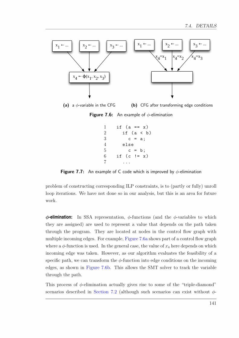
7.4. DETAILS
x1 ← ... x
2 ← ... x
3 ← ...
x4 ← ɸ(x1, x2, x3)
(a) a φ-variable in the CFG
x1 ← ... x
2 ← ... x
3 ← ...
x4=x1 x4=x3x4=x2
(b) CFG after transforming edge conditions
Figure 7.6: An example of φ-elimination
1 if (a == x)
2 if (a < b)
3 c = a;
4 else
5 c = b;
6 if (c != x)
7 ...
Figure 7.7: An example of C code which is improved by φ-elimination
problem of constructing corresponding ILP constraints, is to (partly or fully) unroll
loop iterations. We have not done so in our analysis, but this is an area for future
work.
φ-elimination: In SSA representation, φ-functions (and the φ-variables to which
they are assigned) are used to represent a value that depends on the path taken
through the program. They are located at nodes in the control flow graph with
multiple incoming edges. For example, Figure 7.6a shows part of a control flow graph
where a φ-function is used. In the general case, the value of x4 here depends on which
incoming edge was taken. However, as our algorithm evaluates the feasibility of a
specific path, we can transform the φ-function into edge conditions on the incoming
edges, as shown in Figure 7.6b. This allows the SMT solver to track the variable
through the path.
This process of φ-elimination actually gives rise to some of the “triple-diamond”
scenarios described in Section 7.2 (although such scenarios can exist without φ-
141

CHAPTER 7. AUTOMATED INFEASIBLE PATH DETECTION
elimination). To see how this arises in practice, consider the code in Figure 7.7. Any
loop-free path that executes both lines 3 and 7 is infeasible. We have not shown the
full control flow graph for this example, but there are three edge conditions in the
infeasible set: a = x, c = a, c 6= x.
Curbing complexity: Due to the inherently exponential nature of SMT solving, and
the exponential complexity of the CAMUS algorithm in the presence of multiple
MUSes, we must choose our candidate edges to test with CAMUS carefully. For
programs with longer paths (e.g. 200 edges), there may easily be 10 or more MUSes
on a given worst-case path.
To reduce the complexity of finding these MUSes, we use the observation that con-
flicting edges are generally in close proximity. Given this, we use a small sliding
window over the edges of the candidate path, and use CAMUS to find conflicts over
smaller segments. The sliding window begins with a fixed initial size s0, and moves
forward incrementally by d for each query to CAMUS, partially overlapping with the
previous query. This detects many of the common conflicts quickly. The variables
s0 and d can be tuned based on the efficiency of the SMT solver.
If no conflicts are found after the first pass with the sliding window, we repeat the
process but increasing the size of the sliding window until it either contains an MUS,
or covers the entire path (at which point we know the SMT solver has deemed the
path feasible). In extreme circumstances, the SMT solver may take too long as it
performs a computationally expensive search. In this case, the impatient user can
abort the SMT solver. This construction gives a suitable anytime algorithm, where
the result returned is valid even if interrupted by the user prematurely.
As an example, consider a worst-case path that follows the sequence of edges:
e1, e2, e3, e4, e5, e6, e7, e8
with an initial window size of s0 = 4, and increment of d = 2. We first run
CAMUS over e1, e2, e3, e4, followed by e3, e4, e5, e6, followed by e5, e6, e7, e8.If no MUSes are found, we then expand to e1, e2, . . . , e6 and finally, e1, e2, . . . , e8.
Note that we may not find all MUSes along a specific path, but it is not necessary.
For example, if a path contains one MUS with edges close together (close enough
to fit within a small sliding window), as well as a second MUS where the conflicting
142

7.5. EVALUATION
edges are far apart, we will only find the first MUS. This eliminates the path in
question (and any such paths containing the MUS) and guarantees forwards progress.
We may later encounter the second MUS on a different worst-case path and can
eliminate it then.
Using the sliding window technique, this approach can also be parallelised easily by
processing different fragments of the sliding window on separate cores or machines.
A further optimisation is to remove redundant clauses before applying the CAMUS
algorithm. Many paths often share the same edge condition amongst several edges.
In such cases, only one instance of the edge condition needs to be passed to the
SMT solver.
7.5 Evaluation
7.5.1 seL4
We demonstrate the applicability of our approach by applying it to a worst-case
interrupt response time analysis of the seL4 microkernel. This approach is used
for the analysis performed in Chapter 5, which searches for the path with longest
execution time within the seL4 kernel, beginning at one of the 125 non-preemptible
regions of the kernel, and ending at the exit point of the kernel. In essence, we are
running 125 separate WCET analyses—one for each entry preemption point, and
one for the entry point of the kernel.
Infeasible paths are detected in 45 of the 125 cases. Where infeasible paths are
found, our algorithm arrives at a feasible path after one iteration in 31 cases, after
two iterations in a further 14 cases, and up to 7 for the remaining 3 cases. In two
cases, it reduces the WCET automatically by 23% (from 17 912 cycles to 13 800)
using two iterations and 5 MUSes. The improvements in WCET for all 45 cases
where infeasible paths are detected are shown in Figure 7.8.
Our algorithm detects 252 MUSes when applied to seL4. Note that these are only the
MUSes required to identify specific worst-case execution paths as infeasible. Many
more may exist in the program, but they do not affect our WCET computation. Of
the MUSes found, 20 % are a single-element MUS (an infeasible basic block), 44 %
are pair-wise conflicts, 30 % are 3-way conflicts, and 6 % are 4-way conflicts.
143
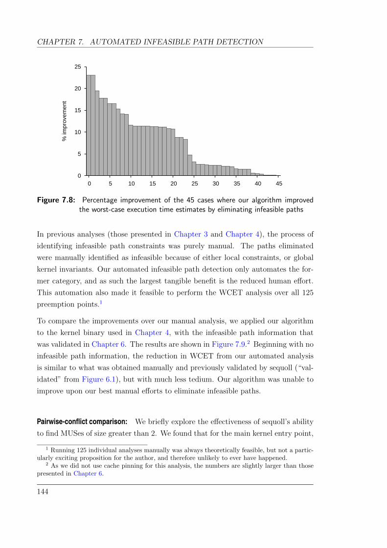
CHAPTER 7. AUTOMATED INFEASIBLE PATH DETECTION
0
5
10
15
20
25
0 5 10 15 20 25 30 35 40 45
% im
pro
vem
ent
Figure 7.8: Percentage improvement of the 45 cases where our algorithm improvedthe worst-case execution time estimates by eliminating infeasible paths
In previous analyses (those presented in Chapter 3 and Chapter 4), the process of
identifying infeasible path constraints was purely manual. The paths eliminated
were manually identified as infeasible because of either local constraints, or global
kernel invariants. Our automated infeasible path detection only automates the for-
mer category, and as such the largest tangible benefit is the reduced human effort.
This automation also made it feasible to perform the WCET analysis over all 125
preemption points.1
To compare the improvements over our manual analysis, we applied our algorithm
to the kernel binary used in Chapter 4, with the infeasible path information that
was validated in Chapter 6. The results are shown in Figure 7.9.2 Beginning with no
infeasible path information, the reduction in WCET from our automated analysis
is similar to what was obtained manually and previously validated by sequoll (“val-
idated” from Figure 6.1), but with much less tedium. Our algorithm was unable to
improve upon our best manual efforts to eliminate infeasible paths.
Pairwise-conflict comparison: We briefly explore the effectiveness of sequoll’s ability
to find MUSes of size greater than 2. We found that for the main kernel entry point,
1 Running 125 individual analyses manually was always theoretically feasible, but not a partic-ularly exciting proposition for the author, and therefore unlikely to ever have happened.
2 As we did not use cache pinning for this analysis, the numbers are slightly larger than thosepresented in Chapter 6.
144

7.5. EVALUATION
Baseline
With detected paths
Optimal
With detected paths
0 100 200 300 400 500 600 700
668
240
518
240
Figure 7.9: Reduction in WCET (in thousands of cycles) through applying automatedinfeasible path detection. The baseline figure uses no infeasible-path infor-mation, while optimal is the best result achieved with manual annotations.
using only pair-wise edge conflicts gave a 4.7% improvement in computed WCET
(compared with no infeasible path detection), whereas using n-way conflicts gave a
10.7% improvement. This difference indicates that eliminating infeasible paths with
n-way conflicts can give notable improvements to WCET estimates.
7.5.2 Comparing CAMUS vs built-in unsat core
We can demonstrate the effectiveness of the CAMUS algorithm by comparing it
with the single unsatisfiable core generated by our SMT solver (Yices 1.0.37). With
either the CAMUS-generated MUSes, or the single “unsat” core provided by Yices,
we are guaranteed to arrive at the same result, assuming that there are no bugs in
the SMT solver.3 What we can evaluate is how much faster we arrive at a feasible
path.
Applying the CAMUS algorithm to seL4 required 67 refinements of the control
flow graph. In comparison, using the unsat core generated by Yices required 152
refinement iterations. However, the number of refinement iterations alone does not
necessarily imply a faster result, as it does not account for the extra runtime of the
CAMUS algorithm. Unfortunately, our implementation (for either approach) is far
3 We encountered one bug in Yices which caused it to crash on certain inputs. The Yicesdevelopers swiftly fixed this bug in the 1.0.37 release.
145
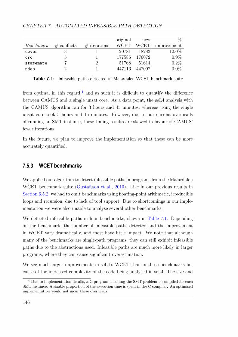
CHAPTER 7. AUTOMATED INFEASIBLE PATH DETECTION
original new %Benchmark # conflicts # iterations WCET WCET improvementcover 3 1 20781 18283 12.0%crc 5 1 177586 176072 0.9%statemate 7 2 51768 51614 0.2%ndes 2 1 447116 447097 0.0%
Table 7.1: Infeasible paths detected in Malardalen WCET benchmark suite
from optimal in this regard,4 and as such it is difficult to quantify the difference
between CAMUS and a single unsat core. As a data point, the seL4 analysis with
the CAMUS algorithm ran for 3 hours and 45 minutes, whereas using the single
unsat core took 5 hours and 15 minutes. However, due to our current overheads
of running an SMT instance, these timing results are skewed in favour of CAMUS’
fewer iterations.
In the future, we plan to improve the implementation so that these can be more
accurately quantified.
7.5.3 WCET benchmarks
We applied our algorithm to detect infeasible paths in programs from the Malardalen
WCET benchmark suite (Gustafsson et al., 2010). Like in our previous results in
Section 6.5.2, we had to omit benchmarks using floating-point arithmetic, irreducible
loops and recursion, due to lack of tool support. Due to shortcomings in our imple-
mentation we were also unable to analyse several other benchmarks.
We detected infeasible paths in four benchmarks, shown in Table 7.1. Depending
on the benchmark, the number of infeasible paths detected and the improvement
in WCET vary dramatically, and most have little impact. We note that although
many of the benchmarks are single-path programs, they can still exhibit infeasible
paths due to the abstractions used. Infeasible paths are much more likely in larger
programs, where they can cause significant overestimation.
We see much larger improvements in seL4’s WCET than in these benchmarks be-
cause of the increased complexity of the code being analysed in seL4. The size and
4 Due to implementation details, a C program encoding the SMT problem is compiled for eachSMT instance. A sizable proportion of the execution time is spent in the C compiler. An optimisedimplementation would not incur these overheads.
146
7.6. RELATED WORK
structure of the seL4 code means that there are many infeasible paths which can
be eliminated. For example, the repeated use of switch statements as described in
Section 4.6 creates many infeasible paths which are detected and eliminated by our
algorithm.
7.6 Related work
The issue of infeasible path detection in static analysis arises not only in the worst-
case execution time domain, but also when generating test vectors (Ngo and Tan,
2008), detecting programming errors (Huuck et al., 2012), and in other general data
flow analyses (Bodık et al., 1997). As such, there has been much research into finding
infeasible paths. However, the domain of worst-case execution time analysis, and
specifically using IPET-based analyses, places many limitations on what infeasible
path information can be utilised. As such, not all techniques for finding infeasible
paths are applicable to IPET.
Engblom and Ermedahl (2000) demonstrate how various types of flow information
can be converted to equations suitable for IPET-based analyses. They divide a
program into “scopes”, which are loop-free subsets of code, and express a number
of different constraint types as ILP equations. These include the same construction
we use for expressing conflicting edges. Their method also supports the ability to
restrict constraints to specific loop iterations. They do not detect any constraints,
but allow a user to provide these annotations more easily.
Suhendra et al. (2006) developed an algorithm to find infeasible paths for WCET
analyses, based on detecting pairwise conflicts between assignments and conditional
branches. Like our approach, they are also limited to finding such conflicts within
loop-free CFGs, and thus treat each loop individually. As they only search for
pairwise conflicts, their algorithm would not detect the case given in our motivating
example.
Gustafsson et al. (2006a) have shown that abstract interpretation can be combined
with symbolic execution to find infeasible paths. Their approach is able to detect
paths with more than two conflicting edges, and is similarly limited to loop-free
segments of code. Their evaluation was only on a single deterministic set of input
values, whereas we are able to support unspecified inputs. Otherwise, their method
shares many similarities with ours—they are limited by the reasoning ability of their
147
CHAPTER 7. AUTOMATED INFEASIBLE PATH DETECTION
symbolic execution engine, whereas we are limited by the reasoning ability of our
SMT solver.
The model-checking-based approach taken by Cassez (2011) to compute WCET
inherently eliminates infeasible paths, as it is guaranteed to find a concrete worst-
case (if the analysis terminates). However, the technique does not scale to programs
the size of seL4.
Huuck et al. (2012) present a method to eliminate infeasible paths for reducing false
positives in static analysis of source code. They use a model checker to identify a
path to an error condition, compute a weakest precondition from the path, and use
an SMT solver to test the validity of the precondition. If the SMT solver shows that
the precondition is unsatisfiable, they augment the model with an “observer” which
encodes the unsatisfiability information and eliminates the path from subsequent
model checking runs. Their approach works on loops, as the loop is detected by
the model checker, and unrolled inside the weakest precondition expression given
to the SMT solver. However, the infeasible path information they detect cannot be
incorporated into an IPET-based WCET analysis.
Banerjee et al. (2013) demonstrate a method to incorporate information from in-
feasible path analysis into the micro-architectural model of the system. They use a
SAT solver to identify infeasible paths in parallel with the micro-architectural mod-
elling phase in order to eliminate spurious machine states which arise due to the
merging of paths in abstract interpretation, thereby reducing overestimation. This
technique complements an existing infeasible path detection algorithm.
Our approach shares conceptual similarities with counterexample-guided abstraction
refinement (CEGAR) algorithms for model checking (Clarke et al., 2003), which were
later extended to software verification (Beyer et al., 2007). CEGAR-style algorithms
use counterexamples to refine the abstraction of a system in order to arrive at a
model with the required precision to solve the problem. Cerny et al. (2013) have
applied CEGAR-like algorithms to general quantitative properties such as WCET.
They demonstrate automated abstraction-refinement schemes of cache behaviour,
using standard CEGAR techniques for eliminating infeasible paths. Their approach
does not however easily integrate into IPET-based analyses.
148

7.7. SUMMARY
7.7 Summary
Eliminating infeasible paths is necessary to obtain good worst-case execution time
estimates on large programs. We have demonstrated a method to automatically
detect infeasible paths within a control flow graph using an SMT solver. We use the
CAMUS algorithm for finding all subsets of mutually unsatisfiable constraints to
speed up the detection of feasible paths, and have shown how to integrate CAMUS
effectively in the context of infeasible path detection.
Our method can detect arbitrary sets of conflicting edges on a control flow graph.
The information about infeasible paths can be easily integrated with an IPET-based
WCET analysis. Being based on an SMT solver, it can detect more complex conflicts
relations than other approaches.
We have evaluated our detection method by applying it to a worst-case execution
time analysis of seL4, where we demonstrate that it can reduce the WCET estimate
by 23%. By using the CAMUS algorithm, we can achieve these results with fewer
iterations than using a single unsatisfiable core obtained from an SMT solver. We
also significantly reduce the amount of labour, and potential for error, that arises
from performing infeasible path elimination manually.
149


Chapter 8
A look at verification and performance
This chapter is based on work presented at APSys 2012 in which I was the primary author
(Blackham and Heiser, 2012).
8.1 Overview
The majority of this thesis has focused on worst-case execution and response times,
in order to provide temporal guarantees. However, overall system performance is still
an important factor in system design. This chapter addresses the interaction between
formal verification and the limits of code optimisation in higher level languages.
Code optimisation plays a large role in overall system performance. Systems de-
signers must pay particular attention to the performance of typical workloads (i.e.
average-case performance), as this directly impacts on power usage (and therefore
battery life), latency, throughput, as well as the hardware cost required to meet
design goals. Code that is shorter or faster can significantly improve performance
across all these factors.
Targeted code optimisation has the greatest impact when applied to the common
case. In many systems, this is often inner loops used for computation, or mundane
but frequent tasks such as copying memory. In microkernel-based systems, the
common case is message-passing inter-process communication (IPC). As a result,
there has been a strong focus on improving the performance of IPC in microkernel-
based systems (Liedtke et al., 1997; Gray et al., 2005).
151
CHAPTER 8. A LOOK AT VERIFICATION AND PERFORMANCE
Many microkernels achieve good performance by providing fastpaths for IPC, which
can improve the performance of IPC operations by an order of magnitude. Fastpaths
are created in order to perform a specific operation for the most common set of
conditions. If any of these conditions do not hold, a fastpath reverts back to the
standard code path through the kernel (referred to as the slowpath). A key property
of a fastpath is that the kernel’s behaviour should be functionally identical with or
without it.
The first L4 microkernels were coded entirely in assembly, in order achieve the
best possible performance from the hardware (L4IMPL). Later versions such as
Hazelnut, Pistachio and Fiasco were written in C or C++, however performance-
critical sections such as the IPC fastpaths were still coded in assembly.
As assembly does not need to comply with any ABIs (other than at the system-call
interface), more opportunities for optimisation are available. For example, all regis-
ters may be utilised, including normally sacred registers such as the stack pointer.
By hand-crafting fastpaths for specific CPUs, authors can minimise pipeline stalls
by careful instruction scheduling, avoid cache misses using strategic prefetching,
and craft the control flow to minimise costly branches. Using these techniques, im-
pressive IPC times have been achieved—e.g. 151 cycles on the ARMv5-based Intel
XScale PXA255 (L4HQ) and 36 cycles on Itanium (Gray et al., 2005).
However, these results challenge maintainability and formal verification. Assembly
code is generally more difficult to read, write and maintain; combined with the non-
conformance to any standard ABIs, fastpaths are extremely fragile, requiring full
knowledge of the system to confidently make any modifications. Even modifications
of seemingly unrelated C code elsewhere in the kernel may impact upon the fastpath.
seL4 similarly has a fastpath which improves the performance of IPC by an order
of magnitude.1 However the fastpath is written in C, as the verification infrastruc-
ture could only formally verify C code, not assembly.2 As a result, we expected a
performance penalty, but estimated it to be less than 10 %.
We have observed that modern C compilers for RISC architectures are becoming
competitive with assembly crafted by a talented and skillful programmer. Using the
1 Efforts have also been devoted to improve seL4’s slowpath performance. This has reduced thegap between slowpath and fastpath performance, but it is still large enough to provide significantbenefit.
2 Recently, researchers at NICTA have achieved formal verification of the assembly code frombinaries compiled with -O1 and most of the binary compiled with -O2 (Sewell et al., 2013).
152
8.2. RELATED WORK
gcc compiler on ARM, we have been able to optimise the compiled machine code by
modifying only the C source code.
We have improved the speed of the fastpath by 35 % through tuning of the C code to
aid compiler optimisations. Our fastpath is competitive with hand-crafted assembly,
and with other microkernels on the same architecture. In this chapter, we explore
various techniques for optimising the assembly output of the compiler by refining the
C code used for IPC. We show that modern compilers can obtain almost all of the
gains attainable with hand-optimised assembly, even for low-level kernel code. The
key insight from this result is that formal verification, and the need to use higher level
languages such as C, does not necessarily require compromising on performance.
8.2 Related work
The debate over the merits of optimisation in assembly code vs C (or other higher-
level languages) dates back to the 1970s and continues on today (Hyde).
Clearly, a knowledgeable and talented assembly developer, given enough time and
resources, can outperform a compiler. However there is the secondary issue of main-
tainability. One can argue that highly-optimised C code requires just as careful
maintenance as an equivalent assembly implementation in order to preserve correct-
ness and performance. We contend that a greater level of skill, knowledge and care
is required to maintain an assembly version.
Whether compilers would ever catch up to the level of a talented assembly devel-
oper is an old question. Massalin (1987) investigated the idea of finding not just
an optimised sequence of instructions, but an optimal sequence for a given loop-free
construct. He wrote a brute-force compiler called a superoptimiser to exhaustively
search for the optimal sequence. Given the exponential nature of the superoptimiser,
it is limited to short sequences of code (a dozen instructions in Massalin’s work).
However the technique has been applied to peephole-optimisations in standard op-
timising compilers (Bansal and Aiken, 2006).
Liedtke (1993a) states that a microkernel should place emphasis on IPC performance
above all other considerations. Optimising for the most common case will clearly
result in the largest gains and for microkernel-based systems that is the IPC path.
For the Pentium, MIPS and Alpha architectures, the inherent architectural costs of
153
CHAPTER 8. A LOOK AT VERIFICATION AND PERFORMANCE
IPC have been shown to range between 45 and 121 cycles (Liedtke et al., 1997). On
the ARM architecture, IPC times as low as 151 cycles have been demonstrated on
the ARMv5 Intel XScale PXA255 (L4HQ). Our experiments focus on the ARM1136
(ARMv6) CPU core, which has a deeper 8-stage pipeline. On this core, previous L4
kernels have achieved 206 cycles for a one-way IPC (Klein et al., 2009b).
Gray et al. (2005) describe their experience optimising the IPC fastpath for the
Itanium processor, with a complex VLIW pipeline. They could reduce their IPC
time from 508 cycles to 36 cycles by hand-optimising their assembly. Due to the
complex VLIW-based pipeline, their compilers struggled to generate efficient code.
Their initial attempt at a hand-crafted assembly path gained a 3x improvement over
the compiled C version. Further refinements, through better instruction scheduling
and eliminating pipeline stalls, resulted in an additional 4.7x improvement and their
final 36 cycle one-way IPC. We believe that on simpler pipelines common to RISC
architectures, modern compilers can achieve closer to optimal output.
8.3 Microkernel IPC
IPC is often provided in both synchronous and asynchronous forms, and seL4 is no
exception. Synchronous IPC transfers a message only when both the sender and
receiver are at a “rendezvous” point – specifically, the sender must be ready to send
and the receiver must be ready to receive. This allows for a direct transfer of data
from sender to receiver. On the other hand, asynchronous IPC does not require the
coordination of threads, as messages are buffered in the kernel until the receiver is
ready receive.
In L4-derived microkernels, synchronous IPC is typically provided by five basic
primitives:
• Send is a one-way message transfer to another thread. The send will block
until the recipient thread is ready to receive.
• Wait receives a message from any thread that is ready to send data to it, or
blocks if no threads are ready to send.
• Call is a combined send and receive operation to another thread, and will run
to completion or fail with an error. It is often used by a client to request an
154
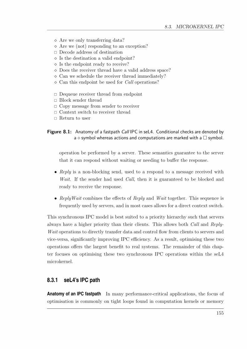
8.3. MICROKERNEL IPC
Are we only transferring data? Are we (not) responding to an exception? Decode address of destination Is the destination a valid endpoint? Is the endpoint ready to receive? Does the receiver thread have a valid address space? Can we schedule the receiver thread immediately? Can this endpoint be used for Call operations?
Dequeue receiver thread from endpoint Block sender thread Copy message from sender to receiver Context switch to receiver thread Return to user
Figure 8.1: Anatomy of a fastpath Call IPC in seL4. Conditional checks are denoted bya symbol whereas actions and computations are marked with a symbol.
operation be performed by a server. These semantics guarantee to the server
that it can respond without waiting or needing to buffer the response.
• Reply is a non-blocking send, used to a respond to a message received with
Wait. If the sender had used Call, then it is guaranteed to be blocked and
ready to receive the response.
• ReplyWait combines the effects of Reply and Wait together. This sequence is
frequently used by servers, and in most cases allows for a direct context switch.
This synchronous IPC model is best suited to a priority hierarchy such that servers
always have a higher priority than their clients. This allows both Call and Reply-
Wait operations to directly transfer data and control flow from clients to servers and
vice-versa, significantly improving IPC efficiency. As a result, optimising these two
operations offers the largest benefit to real systems. The remainder of this chap-
ter focuses on optimising these two synchronous IPC operations within the seL4
microkernel.
8.3.1 seL4’s IPC path
Anatomy of an IPC fastpath In many performance-critical applications, the focus of
optimisation is commonly on tight loops found in computation kernels or memory
155

CHAPTER 8. A LOOK AT VERIFICATION AND PERFORMANCE
Slowpath
Fastpath
0 500 1000 1500
gcc
armcc
1776
308
1441
281
Figure 8.2: One-way cycle counts of the IPC slowpath compared to the original IPCfastpath.
copying. However, in a microkernel-based system, the IPC path, unlike typical
hotspots, has very few tight loops and is largely composed of conditional branches.
This precludes many of the usual optimisation techniques.
Although there are a large number of branches, the majority of these handle ex-
ceptional circumstances. The most common scenario for a synchronous IPC, and
the one that reaps the most benefit in optimising for, is where a thread A sends a
message to a thread B, and:
• thread B is ready and waiting for a message;
• thread B can begin executing immediately under the current scheduling disci-
pline; and
• no error conditions occur.
In such a case, we can pass control flow directly from thread A to thread B, copying
the message directly between the two threads with no buffering.
There are numerous steps and checks involved in handling a common IPC operation
in seL4, such as testing that all objects involved in the operation are valid and in
the correct state for the fastpath. These are shown in Figure 8.1, denoted by a
diamond. If any of the checks fail seL4 reverts to the slowpath. Assuming all the
checks succeed, the fastpath can proceed to transfer the data and control to the new
thread.
Figure 8.2 shows the performance difference between the slowpath and the fastpath
in seL4—the fastpath is 5.6 times faster. Figure 8.3a shows the control flow graph
of the slowpath and offers some insight into why it takes so much time to perform
156

8.3. MICROKERNEL IPC
(a) (b)
Figure 8.3: Control flow graphs of the slowpath (left) and fastpath (right) of seL4.Each node in the graph is a basic-block or a call to a function. The shadednode in the fastpath leads into the slowpath.
precisely the same operation as the fastpath: it must handle all exceptional circum-
stances, which results in a larger cache footprint as well as incurring many branches
and potential branch mispredictions.
Focusing on the common case, we obtain a fastpath with the control flow graph
shown in Figure 8.3b. The shaded node represents a call out to the IPC slowpath.
There are two loops to decode the address of the destination and to transfer the
message data, identified by L1 and L2 on the loops’ entry nodes. A typical IPC in
this fastpath would have almost no branching, except in the message copy. Even
decoding the address requires only a single loop iteration in most systems. We use
this fastpath as our starting point for further optimisation.
157

CHAPTER 8. A LOOK AT VERIFICATION AND PERFORMANCE
8.4 Optimisation techniques
There is a plethora of “collective wisdom” for optimising C code, often given as
simple tips or rules which may allow a compiler to generate better performing code.
These techniques should obviously not be applied blindly, as what performs better
on some architectures may be detrimental on others. Additionally, many of these
techniques, such as loop reversal and unrolling, are performed automatically by
modern compilers.
Our improvements focused on using the gcc compiler (4.6.1), from Mentor Graphics’s
CodeBench Lite 2011.09-69. We also evaluated our improvements with ARM’s own
compiler (armcc 5.01).
The essence of our fastpath optimisation work is to analyse the compiled machine
code from the C compiler and search for missed optimisation opportunities. Op-
portunities may arise in the form of pipeline stalls, redundant calculations, or sub-
optimal data packing. We found that almost all of these can be resolved by modifi-
cations to the C code which gave the compiler more scope for optimisation.
In doing this step-by-step comparison, we performed several simple optimisations
which are commonly a part of the collective wisdom of optimisation, including:
• avoiding unnecessary use of char, short, and signed types to avoid superfluous
sign-extension and zero-extension;
• avoiding unnecessary bit-masking, e.g. when it is known that unused bits will
be zero;
• giving branch hints to achieve straight-line code for the common case;
• avoiding complex expressions which may result in many live registers, leading
to stack spilling.
We also employed some lesser known techniques, described in the following sections,
in order to assist the compiler. We note that even a “smarter” compiler could not
have performed most of these optimisations automatically, as they depend on code
invariants which cannot be detected by static code analysis.
One necessary optimisation for the fastpath was to ensure that all leaf functions were
inlined, in order to avoid unnecessary branching. As both the Call and ReplyWait
158
8.4. OPTIMISATION TECHNIQUES
fastpaths total around 120–130 instructions each, this does not result in a significant
code bloat.
It is also interesting to note that sometimes individual optimisations would not
result in any improvement in performance, as it could be masked by some other
inefficiency. In several cases, gains were only seen after two or more complementary
optimisations being applied together.
8.4.1 Avoiding pipeline stalls
The IPC fastpath is heavily control-oriented—there are many conditional branches
to ensure the conditions for the fastpath are satisfied. Many of these branches
depend on values loaded from memory, and form load-test sequences that create
pipeline stalls.
For example, Figure 8.4 lists a portion of the seL4 fastpath that contains consecutive
branches. Each test depends on loading a value from memory. The generated
assembly code is shown in Figure 8.6. On the ARM1136, each load instruction
(LDR) has a 3-cycle latency for its result. As the results here in r0 and r3 are
required immediately, the CPU is stalled for two cycles after both loads.
With knowledge of the pipeline and the intent of the C code, a human can observe
that the second load can be issued earlier. This speculative loading cannot be
performed by the compiler, as there is no hint to suggest that it is safe to do so—
the validity of the second pointer could depend on the result of the branch.
By “lifting” the load for the second memory access above the first branch, we tell
the compiler that it is safe to issue the memory access earlier. This is shown in
Figure 8.5. The compiler may still choose to defer the load until it is required.
However in this case, the compiler can see the optimisation opportunity to avoid
the pipeline stall, and has sufficient spare registers which can be utilised. The
resulting assembly code in Figure 8.7 has only one stall cycle, saving three cycles off
the execution of the fastpath.
In some cases this type of reordering may slow down a specific path through the
code (e.g. if the value of a lifted load is never used because a branch is taken first).
However, such effects are insignificant compared to the typical execution time of the
slowpath, and it has a net gain on all other paths through a fastpath. We do not
159

CHAPTER 8. A LOOK AT VERIFICATION AND PERFORMANCE
see this effect in Figure 8.7 because the lifted load is inserted where the pipeline was
already stalled.
We discovered many places where this simple optimisation could be used in the
fastpath, giving the compiler more flexibility to schedule instructions.
It should be noted that lifting accesses may not always offer better optimisation
opportunities to the compiler. Due to the possibility of pointer aliasing, a compiler
is not always able to safely reorder a read and a write to memory, even if the
developer knows it to be safe.3 Therefore, lifting a memory load may actually result
in increased register pressure, so this optimisation should be used with care.
8.4.2 Optimised choice of constants
In the ARMv6 architecture, only certain constants can be loaded in a single in-
struction, without the use of literal loads (reading the constant out of memory).
In particular, constants must be expressible as an 8-bit value, shifted left by an
arbitrary offset, and optionally bitwise-negated.
One heavily used constant in seL4 represents an index into the virtual address space
at which some per-address space data is stored. Changing this constant from 0xffe
to 0xff0 allowed this constant to be loaded immediately, avoiding a literal load,
saving both cycles and cache-line usage off the fastpath.
8.4.3 Expressing memory layout
In seL4, the thread object is composite, formed of two smaller objects which are
positioned adjacently in memory—a CNode and a thread control block (TCB), each
256 bytes. Thread objects are always aligned to their size (512 bytes). Often, seL4
is required to access the CNode given a pointer to the TCB. The address for the
CNode was computed by clearing the 8th bit of the TCB address.
This can be optimised by instead of clearing the 8th bit, simply subtracting 28. By
doing so, the compiler is made aware of the actual memory layout of these objects,
which it could not infer when we only cleared the bit (it is possible that the bit may
3Many compilers support strict aliasing, which guarantees that pointers of different types willnever overlap, however the possibility for aliases of pointers of the same type still exists. Therestrict keyword can assist in excluding aliases in this case.
160

8.4. OPTIMISATION TECHNIQUES
/* Check endpoint is not in send state. */
endpoint = *endpointPtr;
if (( endpoint & 0x3) == 0x1) goto slowpath;
/* Check that the caller cap is valid. */
callerCap = *callerCapPtr;
if (callerCap == 0) goto slowpath;
Figure 8.4: An example of C code without lifting optimisation
endpoint = *endpointPtr;
callerCap = *callerCapPtr;
/* Check endpoint is not in send state. */
if (( endpoint & 0x3) == 0x1) goto slowpath;
/* Check that the caller cap is valid. */
if (callerCap == 0) goto slowpath;
Figure 8.5: Code with callerCap load lifted
ldr r0, [r4]
and r3, r0, #3
cmp r3, #1
beq slowpath
ldr r3, [ip, #-208]
cmp r3, #0
beq slowpath
Figure 8.6: Generated assembly without lifting optimisation
ldr r0, [r4]
ldr r3, [ip, #-208]
and r5, r0, #3
cmp r5, #1
beq slowpath
cmp r3, #0
beq slowpath
Figure 8.7: Generated assembly with callerCap load lifted
161
CHAPTER 8. A LOOK AT VERIFICATION AND PERFORMANCE
not have been set in the first place). In particular, it can optimise memory loads
from the CNode given the TCB address by negatively-indexing the TCB address
when performing the memory load. In ARM assembly, this can be expressed as
ldr r0, [r1, #-256], where r1 is the TCB address. Although this only saves one
cycle, it also reduces register pressure, allowing the compiler to use the register for
other optimisations.
8.4.4 Usage of inline assembly
We use assembly code only for hardware-specific operations which cannot be ex-
pressed in C. As the IPC fastpath entails a context switch, it requires accessing
CPU-specific registers which have no C equivalent.
On the ARM11, the kernel must change the page directory and address space iden-
tifier, flush any virtually-addressed caches4, clear the “exclusive monitor” (for syn-
chronisation purposes) and return control back to userspace.
By utilising inline assembly instead of function calls to external assembly routines,
the compiler is not constrained to use the C ABI at these boundaries. This allows for
better register allocation, stack usage and alias analysis. As we inline all assembly
routines, including the return to userspace, the resulting code has no branches in
the case of a 0-length IPC.
8.4.5 Limitations of compiled C
Almost all of the optimisations that we were able to identify could be expressed
equivalently at the C level. Some further optimisations required using assembly,
yet did not give a measurable gain to the IPC fastpath. In particular, we were
able to remove the need for a valid stack. This potentially saves several cycles,
by avoiding unnecessary register loads and memory accesses, and reduces register
pressure. However, despite removing all these superfluous instructions, the overall
cycle count of the IPC fastpath was not reduced, as removing these instructions left
bubbles in the pipeline where it was already stalled.
The register gained (sp) was not useful in the fastpath either, as there were already
4On the ARM1136, although the L1 caches use physical addresses, the branch prediction unituses virtual addresses and thus requires cache flushing on each context switch.
162
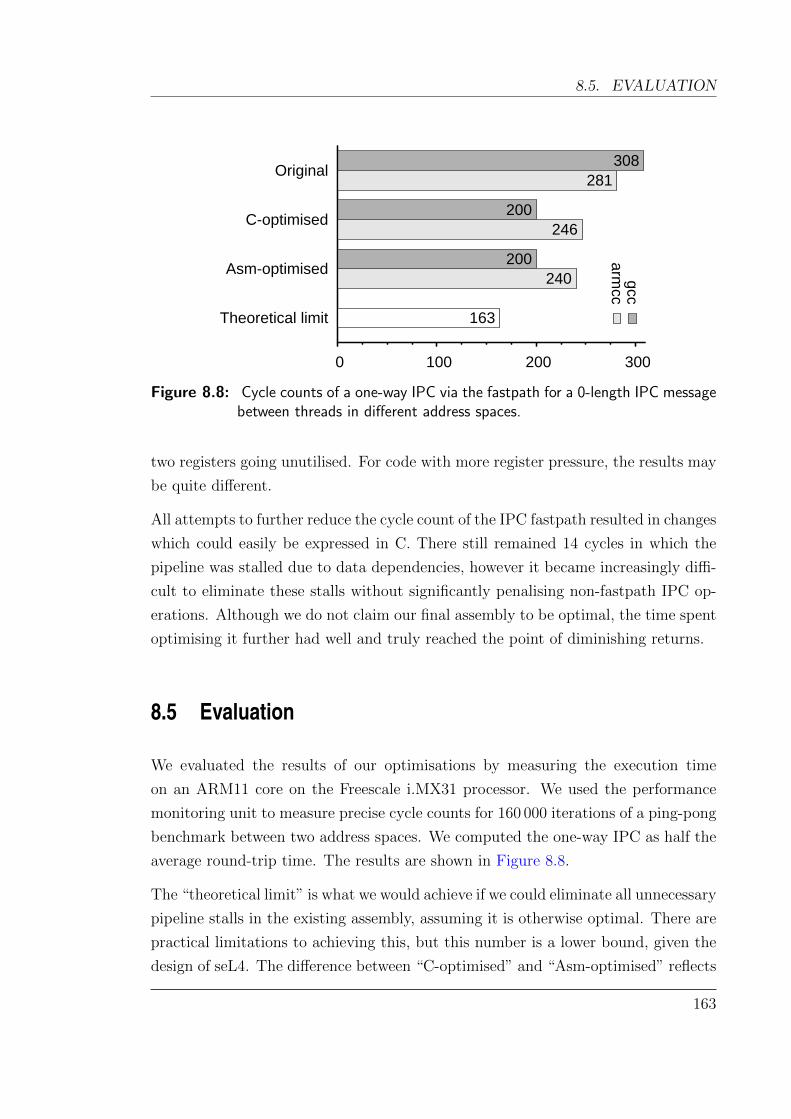
8.5. EVALUATION
Original
C-optimised
Asm-optimised
Theoretical limit
0 100 200 300
gcc
308
200
200 arm
cc
281
246
240
163
Figure 8.8: Cycle counts of a one-way IPC via the fastpath for a 0-length IPC messagebetween threads in different address spaces.
two registers going unutilised. For code with more register pressure, the results may
be quite different.
All attempts to further reduce the cycle count of the IPC fastpath resulted in changes
which could easily be expressed in C. There still remained 14 cycles in which the
pipeline was stalled due to data dependencies, however it became increasingly diffi-
cult to eliminate these stalls without significantly penalising non-fastpath IPC op-
erations. Although we do not claim our final assembly to be optimal, the time spent
optimising it further had well and truly reached the point of diminishing returns.
8.5 Evaluation
We evaluated the results of our optimisations by measuring the execution time
on an ARM11 core on the Freescale i.MX31 processor. We used the performance
monitoring unit to measure precise cycle counts for 160 000 iterations of a ping-pong
benchmark between two address spaces. We computed the one-way IPC as half the
average round-trip time. The results are shown in Figure 8.8.
The “theoretical limit” is what we would achieve if we could eliminate all unnecessary
pipeline stalls in the existing assembly, assuming it is otherwise optimal. There are
practical limitations to achieving this, but this number is a lower bound, given the
design of seL4. The difference between “C-optimised” and “Asm-optimised” reflects
163
CHAPTER 8. A LOOK AT VERIFICATION AND PERFORMANCE
optimisations which could not be performed at the C level (e.g. discarding the stack
and repurposing the stack pointer).
The best results were obtained using the gcc compiler. Although armcc often gen-
erates better optimised code than gcc, it was unable to optimise our fastpath as
effectively. We found that this occurred for the following reasons:
• armcc did not order code optimally, despite hints using __builtin_expect().
As a result, there were 7 more branch mispredictions in the armcc version
compared to the result from gcc. These mispredictions account for over 90 %
of the difference between gcc and armcc fastpaths.
• armcc saves most registers onto the stack, as it does not use the noreturn
attribute as a hint that it can be avoided. This contributes two extra cycles
to the armcc-compiled fastpath.
• armcc’s inline assembler does not support the instructions to directly return
to userspace. Instead, a call to an external function must be used. This
contributes four extra cycles to the armcc-compiled fastpath.
We also measured the effect of compiling seL4 for ARM’s size-optimised Thumb
instruction set. Thumb reduced the size of the compiled fastpath (in bytes) by
20 %, but increased the cycle count by over 80 %, as significantly more instructions
were needed.
8.6 Discussion
Using optimisations at the C level has allowed us to reduce the one-way IPC times by
35 %. Using modifications to the assembly code, we were able to remove superfluous
instructions, but we were unable to reduce the execution time further. Given our
experiences, we claim that for heavily control-oriented code such as the fastpath,
and for our register-rich RISC platform, human-guided compilers can achieve almost
as good a result as hand-optimised assembly.
Our experiments were performed on a single-issue pipeline, common to many embed-
ded systems. Multiple-issue (e.g. superscalar or VLIW) pipelines pose interesting
optimisation challenges both for compilers and humans.
164
8.6. DISCUSSION
There may be situations where the compilers are not aware of (or are unable to
generate) instructions that would lead to more optimised output. Inline assembly
may be able to assist in some of these cases, whilst keeping the majority of the code
in C.
Optimisation effort We dedicated around two person-weeks of work to optimising
the C fastpath. Like many optimisation efforts, we achieved the majority of our
gains within the first 30 % of the work, rapidly reaching the point of diminishing
returns. We estimate that optimising an assembly implementation would require
at least twice as much effort, and significantly increase the subsequent maintenance
burden.
Maintenance There are two distinct aspects to maintaining code such as the fast-
path: performance and correctness. One disadvantage of a C-optimised fastpath is
that the performance is highly sensitive to changes in the compiler. Vigilant perfor-
mance regression testing is required to ensure that the optimisation efforts do not
bit rot.
However, we claim that C code is significantly easier to understand, and to main-
tain correctness of, than the equivalent assembly implementation. Changes to data
structures are much easier to incorporate into C than in assembly.
Portability The majority of our optimisations do not target a specific architecture or
compiler—they simply present further optimisation opportunities for the compiler.
For example, if there existed a superoptimiser capable of scaling to produce optimal
machine code for the fastpath, it too would be assisted by our optimisations.
Verification The IPC fastpath is a verified part of the seL4 microkernel—i.e. there
is a machine-checked formal proof that it adheres to the functional specification and
preserves all invariants within the kernel. By limiting our optimisations to the C
code, we retain the ability to verify the fastpath.
Cache layout The majority of IPC benchmarks are focused on hot-cache perfor-
mance. Ideally, all memory accesses are in the L1 cache, which on our platform can
165

CHAPTER 8. A LOOK AT VERIFICATION AND PERFORMANCE
be accessed in a single cycle. However, even for hot-cache performance, pathological
memory layouts may lead to conflict misses and significantly degrade performance.
There are approximately 120 unique instructions executed by a one-way IPC, giving
an instruction-cache footprint of 18 cache lines. Due to the compactness of the
IPC fastpath, and the ease with which code placement in the microkernel can be
manipulated, it is simple to avoid instruction-cache conflicts.
The data-cache footprint of the IPC fastpath is 22 cache lines. However, due to
the nature of object alignment in seL4, there is very little entropy in the lower
address bits of some objects. For example, a thread object in seL4 is 29 bytes, and a
single way of the 4-way set-associative L1 cache on our processor is 212 bytes. This
means that given two different threads in seL4, there are only three bits available
that determine the possible cache lines for the thread object, greatly increasing the
chances of cache collisions, even in hot-cache scenarios.
8.7 Summary
We have demonstrated that for heavily control-oriented code, it is possible to per-
form significant optimisations at the C level. Modern compilers are sufficiently
advanced that they can recognise many optimisation opportunities. Where optimi-
sations are missed by the compiler, it is often due to a lack of insight available to
the compiler, and can be resolved through modifications to the C sources.
Using carefully guided optimisations on the IPC fastpath, we were able to attain all
of the possible optimisations we could conceive without resorting to hand-crafting
assembly code. On RISC platforms such as ours, the need to write fastpaths in
assembly to get maximum performance is questionable when modern compilers can
achieve similar results in C.
Although these are preliminary results on two specific code paths, we believe that
the techniques here can generalise to hot code paths in both kernels and general
userspace code. We also note that this approach is heavily used in the high-
performance commercial OKL4 microvisor (Heiser and Leslie, 2010) and its deriva-
tives to ease portability and maintainability.
Maximising the benefits of compiler optimisations often requires an intricate under-
standing of the details of the microarchitecture and closely inspect the generated
166

8.7. SUMMARY
assembly code. This is no different to the depth of knowledge required to optimise
an assembly implementation. However, by performing optimisations at the C level,
we retain expressiveness, reduce maintenance overhead, and can make use of current
formal verification techniques.
167

Chapter 9
Conclusion
9.1 Summary
In this thesis, we have explored several aspects of building trustworthy mixed-
criticality real-time systems. Mixed-criticality systems are a promising approach
for reducing design and production costs by integrating mission-critical function-
ality with convenience features on the same CPU. In order to make such systems
trustworthy, we need strong guarantees on both their functional and temporal be-
haviour.
We propose that a verified microkernel such as seL4 is well suited to fulfill these
guarantees. The formal verification of seL4 ensures that the C source code, and
also the compiled binary, behave as specified. Additional proofs also show that
seL4 preserves integrity and confidentially, guaranteeing that separated components
cannot affect each other.
We have focused on complementing these functional guarantees with timing guar-
antees. Safe bounds on seL4’s interrupt response time allow hard real-time systems
to be constructed on top of the seL4 microkernel, with unprecedented levels of as-
surance. To achieve this, we have investigated the worst-case interrupt response
time of seL4, and explored what is required to make it suitable for a wider class of
real-time systems.
169
CHAPTER 9. CONCLUSION
9.2 Contributions
The contributions of this thesis are summarised as follows.
In Chapter 3, we adapted state-of-the-art tools to compute safe upper bounds on the
WCET of the complete seL4 microkernel. This is the first such published WCET
analysis of any protected general-purpose operating system kernel, and we believe it
to be the largest code base on which a fully context-aware WCET analysis has been
performed. The computed interrupt latencies were well over a millisecond—well
beyond the acceptable limits for some real-time systems—thus raising the issue of
how they could be improved.
We found that modifications to reduce the interrupt latency needed to be done
with care in order to ensure the resulting kernel could still be formally verified. In
Chapter 4 we explored how this could be achieved, and described the design principle
of incremental consistency which simultaneously enables small bounded execution
times and aids formal verification. Applying this principle to seL4, and guided by
our WCET analysis, we managed to reduce the interrupt latency of seL4 by an order
of magnitude, down to several hundred microseconds.
As many application domains require even shorter latencies, in Chapter 5 we ex-
plored the limits of how short the latency of a non-preemptible kernel such as seL4
could be made. To achieve this, we had to forgo the requirement of formal verifi-
cation on seL4, but we maintained a design which was still amenable to reasonably
comprehensive testing and analysis by avoiding concurrency. With some targeted
improvements, we were able to reduce seL4’s interrupt latency by a further order
of magnitude, to tens of microseconds. This satisfies the majority of hard real-time
application domains, though there is still scope to reduce this further.
In the pursuit of computing safe bounds on seL4’s interrupt latency, we created
a framework which could analyse compiled binaries in order to validate manual
annotations used for the earlier WCET analyses. In Chapter 6, we presented the
sequoll framework which used model checking in order to automatically compute
the loop bounds of loops in the seL4 binary, as well as test the validity of some
infeasible path constraints.
We further improved the utility of sequoll in Chapter 7, where we presented a
technique to automatically detect infeasible path constraints. The resulting analysis
method efficiently and effectively eliminated a substantial amount of human effort
170
9.3. FUTURE WORK
in performing a tight WCET analysis.
Finally, in Chapter 8 we have shown that performance-critical code such as the
IPC fastpath does not need to be written in low-level assembly to achieve good
performance. The implication of this for trustworthy real-time systems is that such
code can be written in C and thereby be formally verified using existing verification
tools. This demonstrates that it is possible to write fast, maintainable and provably
correct code. Trustworthy mixed-criticality systems require this ability in order to
deliver acceptable performance.
9.3 Future work
The ideas and results of this thesis integrate many different areas of research—
that of formal verification, program analysis, real-time systems, kernel design, and
program optimisation. The directions in which these lead are equally, if not more,
diverse.
One area of improvement is the accuracy of our WCET analyses. As we have
noted, some WCET analysis methods promise much more precise estimates, but
scale poorly in the face of several thousand lines of code (such as the seL4 micro-
kernel). Thus we used techniques with coarser approximations which provide better
scalability in order to compute seL4’s WCET. There is scope to improve this by, for
example, using precise model-checking-based approaches for computing basic blocks
or even larger sections of code, and using scalable IPET-based solutions for com-
puting the global WCET, as suggested by Huber and Schoeberl (2009). This is the
most promising approach for tighter analyses of non-preemptible OS kernels, where
the analysed code paths can be relatively long.
Another direction to improve the WCET analysis of a verified microkernel such as
seL4, is to make use of formally-verified invariants in computing the WCET. In
particular, many infeasible paths can only be detected with knowledge of global
program invariants. Many of these invariants exist within the proof, but are not
presently available to the WCET analysis. The sequoll framework lays down the
foundations to support reasoning about these infeasible paths, using either model
checkers or SMT solvers. A significant challenge is expressing the high-level invari-
ants on abstract objects in terms of bytes, registers and memory words. Sewell
et al. (2013) have recently shown how to compute a correspondence between C and
171
CHAPTER 9. CONCLUSION
optimised machine code, thereby guaranteeing that the machine code maintains the
high-level invariants. Their work may assist significantly in reusing the invariants
at the machine-code level.
Following the formal verification thread, we could gain even stronger confidence in
the timing guarantees of seL4 by also integrating time itself into a formal proof
framework. At present, our timing guarantees are based on implementations of
various algorithms. Although the algorithms and theories are considered sound,
bugs in the implementation can easily undermine any such guarantees. Integrating
WCET execution time into the formal proof is a logical progression for a high-
assurance kernel. This idea has been explored by Fidge et al. (1997), who present
a software development methodology where execution time is a first-class concept.
There remain many hurdles and much effort required to realise this for a complex
code base such as seL4.
From Chapter 5, it remains to be seen as to how small the worst-case interrupt
latency (to userspace) of a non-preemptible kernel can be. Similarly, it also remains
open as to what the worst-case interrupt latency of an equivalent fully-preemptible
kernel would be. We propose that they could be within an order of magnitude, but
a deeper analysis is required.
Finally, an aspect largely untapped by this thesis has been the extension to multi-
core mixed-criticality real-time systems. As multi-core processors are becoming
the norm, even on embedded hardware, multi-core mixed-criticality systems have
become an active research area spanning a wide variety of issues including WCET
estimation (Chattopadhyay et al., 2012), scheduling (Mollison et al., 2010), kernel
design (Baumann et al., 2009) and formal verification (von Tessin, 2012). There are
still many open problems in delivering high-performance and high-assurance systems
on top of multi-core architectures.
172
References
Eyad Alkassar, Mark Hillebrand, Wolfgang Paul, and Elena Petrova. Automated verifi-cation of a small hypervisor. In Gary Leavens, Peter O’Hearn, and Sriram Rajamani,editors, Proceedings of Verified Software: Theories, Tools and Experiments 2010, vol-ume 6217 of Lecture Notes in Computer Science, pages 40–54. Springer, 2010. ISBN978-3-642-15056-2.
ARINC, 2012. Avionics application software standard interface, November 2012. ARINCStandard 653.
ARM1136JF-S and ARM1136J-S Technical Reference Manual. ARM Ltd., R1P1 edition,2005.
Ben Avison. ARM Cortex-A8 instruction timings. http://www.avison.me.uk/ben/
programming/cortex-a8.html, 2010. Visited 17 March 2013.
James Bailey and Peter J. Stuckey. Discovery of minimal unsatisable subsets of constraintsusing hitting set dualization. In Proceedings of the 7th International Symposium onPractical Aspects of Declarative Languages, pages 174–186, Long Beach, CA, 2005.Springer-Verlag.
T. P. Baker. Stack-based scheduling for realtime processes. Journal of Real–Time Systems,3(1):67–99, 1991.
Abhijeet Banerjee, Sudipta Chattopadhyay, and Abhik Roychoudhury. Precise micro-architectural modeling for WCET analysis via AI+SAT. In Proceedings of the 19thIEEE Real-Time and Embedded Technology and Applications Symposium, Philadelphia,USA, April 2013.
Sorav Bansal and Alex Aiken. Automatic generation of peephole superoptimizers. In Pro-ceedings of the 12th International Conference on Architectural Support for ProgrammingLanguages and Operating Systems, New York, NY, USA, 2006. ACM.
Sebastien Bardin, Philippe Herrmann, Jerome Leroux, Olivier Ly, Renaud Tabary, andAymeric Vincent. The BINCOA framework for binary code analysis. In Proceedingsof the 23rd International Conference on Computer Aided Verification, pages 165–170,Snowbird, UT, 2011a. Springer-Verlag.
Sebastien Bardin, Philippe Herrmann, and Franck Vedrine. Refinement-based CFG recon-struction from unstructured programs. pages 54–69, Berlin, Heidelberg, 2011b. Springer-Verlag.
173
REFERENCES
Sanjoy Baruah and Gerhard Fohler. Certification-cognizant time-triggered scheduling ofmixed-criticality systems. In Proceedings of the 32nd IEEE Real-Time Systems Sympo-sium, pages 3–12, Dec 2011. doi: 10.1109/RTSS.2011.9.
S.K. Baruah, A. Burns, and R.I. Davis. Response-time analysis for mixed criticalitysystems. In Proceedings of the 32nd IEEE Real-Time Systems Symposium, pages 34–43,Dec 2011. doi: 10.1109/RTSS.2011.12.
Andrew Baumann, Paul Barham, Pierre-Evariste Dagand, Tim Harris, Rebecca Isaacs,Simon Peter, Timothy Roscoe, Adrian Schupbach, and Akhilesh Singhania. The mul-tikernel: A new OS architecture for scalable multicore systems. In Proceedings of the22nd ACM Symposium on Operating Systems Principles, Big Sky, MT, USA, October2009. ACM.
Christoph Baumann, Bernhard Beckert, Holger Blasum, and Thorsten Bormer. Ingredientsof operating system correctness. In Embedded World Conference, Nuremberg, Germany,March 2010.
Christoph Baumann, Bernhard Beckert, Holger Blasum, and Thorsten Bormer. Lessonslearned from microkernel verification: Specification is the new bottleneck. In Proceedingsof the 7th Systems Software Verification, 2012.
Gerd Behrmann, Alexandre David, and Kim G. Larsen. A tutorial on UPPAAL. In MarcoBernardo and Flavio Corradini, editors, Formal Methods for the Design of Real-TimeSystems, volume 3185 of Lecture Notes in Computer Science, pages 200–236. Springer,Berlin, Heidelberg, 2004.
Gerd Behrmann, Agnes Cougnard, Alexandre David, Emmanuel Fleury, Kim G. Larsen,and Didier Lime. UPPAAL-Tiga: Time for playing games! In Proceedings of the 19thInternational Conference on Computer Aided Verification, pages 121–125. Springer,Berlin, Heidelberg, 2007.
Dirk Beyer, Thomas A. Henzinger, Ranjit Jhala, and Rupak Majumdar. The softwaremodel checker BLAST: Applications to software engineering. International Journal onSoftware Tools for Technology Transfer, 9(5):505–525, 2007.
Sven Beyer, Christian Jacobi, Daniel Kroning, Dirk Leinenbach, and Wolfgang J. Paul.Putting it all together—formal verification of the VAMP. International Journal onSoftware Tools for Technology Transfer (STTT), 8(4):411–430, 2006.
Bernard Blackham and Gernot Heiser. Correct, fast, maintainable – choose any three!In Proceedings of the 3rd Asia-Pacific Workshop on Systems (APSys), pages 13:1–13:7,Seoul, Korea, July 2012. doi: 10.1145/2349896.2349909.
Bernard Blackham and Gernot Heiser. Sequoll: a framework for model checking binaries.In Eduardo Tovar, editor, IEEE Real-Time and Embedded Technology and ApplicationsSymposium, pages 97–106, Philadelphia, USA, April 2013a. ISBN 978-1-4799-0184-5.
Bernard Blackham and Gernot Heiser. Sequoll: a framework for model checking binaries.In Proceedings of the 19th IEEE Real-Time and Embedded Technology and ApplicationsSymposium, Philadelphia, USA, April 2013b.
174

REFERENCES
Bernard Blackham, Yao Shi, Sudipta Chattopadhyay, Abhik Roychoudhury, and GernotHeiser. Timing analysis of a protected operating system kernel. In Proceedings of the32nd IEEE Real-Time Systems Symposium, pages 339–348, Vienna, Austria, November2011a. doi: 10.1109/RTSS.2011.38.
Bernard Blackham, Yao Shi, and Gernot Heiser. Protected hard real-time: The nextfrontier. In Proceedings of the 2nd Asia-Pacific Workshop on Systems (APSys), pages1:1–1:5, Shanghai, China, July 2011b. doi: 10.1145/2103799.2103801.
Bernard Blackham, Yao Shi, and Gernot Heiser. Improving interrupt response time in averifiable protected microkernel. In Proceedings of the 7th EuroSys Conference, pages323–336, Bern, Switzerland, April 2012a. doi: 10.1145/2168836.2168869.
Bernard Blackham, Vernon Tang, and Gernot Heiser. To preempt or not to preempt, thatis the question. In Proceedings of the 3rd Asia-Pacific Workshop on Systems (APSys),pages 8:1–8:7, Seoul, Korea, July 2012b. doi: 10.1145/2349896.2349904.
Regis Blanc, Thomas A. Henzinger, Thibaud Hottelier, and Laura Kovacs. ABC: algebraicbound computation for loops. In Proceedings of the 16th International Conference onLogic for Programming, Artificial Intelligence and Reasoning, pages 103–118, Berlin,Heidelberg, 2010. Springer-Verlag.
Rastislav Bodık, Rajiv Gupta, and Mary-Lou Soffa. Refining data flow information usinginfeasible paths. In Mehdi Jazayeri and Helmut Schauer, editors, Software EngineeringESEC/FSE’97, volume 1301 of Lecture Notes in Computer Science, pages 361–377.Springer Berlin Heidelberg, 1997.
Manfred Broy, Samarjit Chakraborty, Dip Goswami, S. Ramesh, M. Satpathy, StefanResmerita, and Wolfgang Pree. Cross-layer analysis, testing and verification of automo-tive control software. In Proceedings of the 11th International Conference on EmbeddedSoftware, pages 263–272, New York, NY, USA, 2011. ACM.
Claire Burguiere and Christine Rochange. History-based schemes and implicit path enu-meration. In Proceedings of the 6th Workshop on Worst-Case Execution-Time Analysis,2006.
Marti Campoy, A. Perles Ivars, and J. V. Busquets Mataix. Static use of locking caches inmultitask preemptive real-time systems. In Proceedings of IEEE/IEE Real-Time Em-bedded Systems Workshop, 2001. Satellite of the IEEE Real-Time Systems Symposium.
Martin Carlsson, Jakob Engblom, Andreas Ermedahl, Jan Lindblad, and Bjorn Lisper.Worst-case execution time analysis of disable interrupt regions in a commercial real-time operating system. In Proceedings of the 2nd International Workshop on Real-TimeTools, 2002.
Franck Cassez. Timed games for computing WCET for pipelined processors with caches.In Proceedings of the 11th International Conference on Application of Concurrency toSystem Design, pages 195–204. IEEE Computer Society, June 2011.
175

REFERENCES
Franck Cassez, Ren Rydhof Hansen, and Mads Olesen. What is a timing anomaly?In Tullio Vardanega, editor, 12th International Workshop on Worst-Case Execution-Time Analysis (WCET), pages 1–12, Pisa, Italy, July 2012. Schloss Dagstuhl - Leibniz-Zentrum fuer Informatik. ISBN http://dx.doi.org/10.4230/OASIcs.WCET.2012.1.
Roderick Chapman, Andy Wellings, and Alan Burns. Integrated program proof and worst-case timing analysis of spark ada. In Proceedings of the Workshop on Language, Com-piler, and Tool Support for Real-Time Systems, June 1994.
Sudipta Chattopadhyay and Abhik Roychoudhury. Unified cache modeling for WCETanalysis and layout optimizations. In Proceedings of the 30th IEEE Real-Time SystemsSymposium, 2009.
Sudipta Chattopadhyay, Chong Lee Kee, and Abhik Roychoudhury. A unified WCETanalysis framework for multi-core platforms. In Proceedings of the 18th IEEE Real-Time and Embedded Technology and Applications Symposium, 2012.
Stephen Checkoway, Damon McCoy, Brian Kantor, Danny Anderson, Hovav Shacham,Stefan Savage, Karl Koscher, Alexei Czeskis, Franziska Roesner, and Tadayoshi Kohno.Comprehensive experimental analyses of automotive attack surfaces. In Proceedings ofthe 20th USENIX Security Symposium, 2011.
Vitaly Chipounov, Volodymyr Kuznetsov, and George Candea. The S2E platform: Design,implementation, and applications. ACM Transactions on Computer Systems, 30(1):2:1–2:49, February 2012. ISSN 0734-2071.
Alessandro Cimatti, Edmund Clarke, Enrico Giunchiglia, Fausto Giunchiglia, Marco Pi-store, Marco Roveri, Roberto Sebastiani, and Armando Tacchella. NuSMV version 2:An opensource tool for symbolic model checking. In Proceedings of the 14th Interna-tional Conference on Computer Aided Verification, volume 2404 of LNCS, Copenhagen,Denmark, July 2002. Springer.
Edmund Clarke, Orna Grumberg, Somesh Jha, Yuan Lu, and Helmut Veith.Counterexample-guided abstraction refinement for symbolic model checking. Journalof the ACM, 50(5):752–794, September 2003.
Ernie Cohen, Markus Dahlweid, Mark Hillebrand, Dirk Leinenbach, Micha l Moskal,Thomas Santen, Wolfram Schulte, and Stephan Tobies. VCC: A practical system forverifying concurrent C. In Stefan Berghofer, Tobias Nipkow, Christian Urban, andMarkus Wenzel, editors, Proceedings of the 22nd International Conference on TheoremProving in Higher Order Logics, volume 5674 of Lecture Notes in Computer Science,pages 23–42, Munich, Germany, 2009. Springer.
Antoine Colin and Isabelle Puaut. A modular and retargetable framework for tree-basedWCET analysis. In Proceedings of the 13th Euromicro Conference on Real-Time Sys-tems, pages 191–198, Delft, Netherlands, June 13–15 2001a.
Antoine Colin and Isabelle Puaut. Worst case execution time analysis of the RTEMS real-time operating system. In Proceedings of the 13th Euromicro Conference on Real-TimeSystems, pages 191–198, Delft, Netherlands, June 13–15 2001b.
176
REFERENCES
Patrick Cousot and Radhia Cousot. Abstract interpretation: a unified lattice model forstatic analysis of programs by construction or approximation of fixpoints. In Proceed-ings of the 4th ACM SIGPLAN-SIGACT Symposium on Principles of ProgrammingLanguages, pages 238–252, Los Angeles, CA, USA, 1977. ACM Press.
Christoph Cullmann and Florian Martin. Data-flow based detection of loop bounds. InProceedings of the 7th Workshop on Worst-Case Execution-Time Analysis, 2007.
Ron Cytron, Jeanne Ferrante, Barry K. Rosen, Mark N. Wegman, and F. Kenneth Zadeck.Efficiently computing static single assignment form and the control dependence graph.ACM Transactions on Programming Languages and Systems, 13:451–490, October 1991.
Andreas Engelbredt Dalsgaard, Mads Chr. Olesen, Martin Toft, Rene Rydhof Hansen, andKim Guldstrand Larsen. METAMOC: Modular execution time analysis using modelchecking. In Proceedings of the 10th Workshop on Worst-Case Execution-Time Analysis,pages 113–123, Brussels, Belgium, July 2010.
Matthias Daum, Stefan Maus, Norbert Schirmer, and M. Nassim Seghir. Integration of asoftware model checker into Isabelle. In Proceedings of the 12th International Conferenceon Logic for Programming, Artificial Intelligence and Reasoning, pages 381–395, Berlin,Heidelberg, 2005. Springer-Verlag. doi: 10.1007/11591191 27.
Matthias Daum, Jan Dorrenbacher, and Burkhart Wolff. Proving fairness and implemen-tation correctness of a microkernel scheduler. Journal of Automated Reasoning: SpecialIssue on Operating System Verification, 42(2–4):349–388, 2009a.
Matthias Daum, Norbert W. Schirmer, and Mareike Schmidt. Implementation correctnessof a real-time operating system. In IEEE International Conference on Software Engi-neering and Formal Methods, pages 23–32, Hanoi, Vietnam, 2009b. IEEE ComputerSociety.
Jack B. Dennis and Earl C. Van Horn. Programming semantics for multiprogrammedcomputations. Communications of the ACM, 9:143–155, 1966.
Jean-Francois Deverge and Isabelle Puaut. Safe measurement-based WCET estimation.In Proceedings of the 5th Workshop on Worst-Case Execution-Time Analysis, pages13–16, 2005.
Richard P. Draves, Brian N. Bershad, Richard F. Rashid, and Randall W. Dean. Usingcontinuations to implement thread management and communication in operating sys-tems. In Proceedings of the 13th ACM Symposium on Operating Systems Principles,Asilomar, CA, USA, October 1991.
Bruno Dutertre and Leonardo de Moura. The Yices SMT solver. http://yices.csl.
sri.com/tool-paper.pdf, August 2006. Visited 17 March 2013.
Dhammika Elkaduwe, Philip Derrin, and Kevin Elphinstone. A memory allocation modelfor an embedded microkernel. In Proceedings of the 1st International Workshop onMicrokernels for Embedded Systems (MIKES), pages 28–34, Sydney, Australia, January2007. NICTA.
177
REFERENCES
Jakob Engblom and Andreas Ermedahl. Modeling complex flows for worst-case executiontime analysis. In Proceedings of the 21st IEEE Real-Time Systems Symposium, 2000.
Dawson R. Engler, M. Frans Kaashoek, and James O’Toole, Jr. Exokernel: An operat-ing system architecture for application-level resource management. In Proceedings ofthe 15th ACM Symposium on Operating Systems Principles, pages 251–266, CopperMountain, CO, USA, December 1995.
Michael D. Ernst, Jeff H. Perkins, Philip J. Guo, Stephen McCamant, Carlos Pacheco,Matthew S. Tschantz, and Chen Xiao. The Daikon system for dynamic detection oflikely invariants. Science of Computer Programming, 69(1–3):35–45, December 2007.
Ansgar Fehnker, Ralf Huuck, Patrick Jayet, Michel Lussenburg, and Felix Rauch. Goanna— A Static Model Checker. In Proceedings of the 11th International Workshop on For-mal Methods for Industrial Critical Systems (FMICS), pages 297–300, Bonn, Germany,August 2006.
Xingu Feng, Zhong Shao, Yuan Dong, and Yu Guo. Certifying low-level programs withhardware interrupts and preemptive threads. In ACM SIGPLAN Conference on Pro-gramming Language Design and Implementation, pages 170–182, Tucson, AZ, USA,June 2008.
Christian Ferdinand and Reinhold Heckmann. aiT: worst case execution time predictionby static program analysis. In IFIP Congress Topical Sessions, pages 377–384, 2004.
Colin J. Fidge, Peter Kearney, and Mark Utting. A formal method for building concurrentreal-time software. IEEE Software, 14(2):99–106, 1997.
Bryan Ford, Mike Hibler, Jay Lepreau, Roland McGrath, and Patrick Tullmann. Interfaceand execution models in the Fluke kernel. In Proceedings of the 3rd USENIX Symposiumon Operating Systems Design and Implementation, pages 101–115, New Orleans, LA,USA, February 1999. USENIX.
Anthony Fox. Directions in ISA specification. In 3rd International Conference on Inter-active Theorem Proving, Lecture Notes in Computer Science, Princeton, New Jersey,August 2012. Springer.
Anthony Fox and Magnus Myreen. A trustworthy monadic formalization of the ARMv7instruction set architecture. In Matt Kaufmann and Lawrence C. Paulson, editors, 1stInternational Conference on Interactive Theorem Proving, volume 6172 of Lecture Notesin Computer Science, pages 243–258, Edinburgh, UK, July 2010. Springer.
Alexey Gotsman and Hongseok Yang. Modular verification of preemptive OS kernels.Proceedings of the 16th International Conference on Functional Programming, pages404–417, 2011. doi: http://doi.acm.org/10.1145/2034773.2034827.
Rene Graf. Embedded systems in automation: Commodities and challenges. In 7th IEEEInternational Symposium on Industrial Embedded Systems (SIES), Karlsrhue, Germany,2012. Slides: http://www.iestcfa.org/presentations/sies2011/rene_graf.pdf.
178

REFERENCES
Charles Gray, Matthew Chapman, Peter Chubb, David Mosberger-Tang, and GernotHeiser. Itanium — a system implementor’s tale. In Proceedings of the 2005 USENIXAnnual Technical Conference, pages 264–278, Anaheim, CA, USA, April 2005.
Green Hills Software. INTEGRITY real-time operating system. http://www.ghs.com/
products/rtos/integrity.html. Visited 17 March 2013.
Jan Gustafsson. Analyzing Execution-Time of Object-Oriented Programs Using AbstractInterpretation. PhD. thesis, Uppsala University, May 2000.
Jan Gustafsson, Andreas Ermedahl, and Bjorn Lisper. Algorithms for infeasible path cal-culation. In Proceedings of the 6th Workshop on Worst-Case Execution-Time Analysis,2006a.
Jan Gustafsson, Andreas Ermedahl, Christer Sandberg, and Bjorn Lisper. Automaticderivation of loop bounds and infeasible paths for WCET analysis using abstract exe-cution. In Proceedings of the 27th IEEE Real-Time Systems Symposium, pages 57–66,Washington, DC, USA, 2006b. IEEE Computer Society. doi: 10.1109/RTSS.2006.12.
Jan Gustafsson, Adam Betts, Andreas Ermedahl, and Bjorn Lisper. The MalardalenWCET benchmarks – past, present and future. In Proceedings of the 10th Workshopon Worst-Case Execution-Time Analysis, pages 137–147, Brussels, Belgium, July 2010.OCG.
Hermann Hartig, Michael Hohmuth, and Jean Wolter. Taming Linux. In Proceedings ofthe 5th Workshop on Power Aware Real-time Computing, 1998.
Paul Havlak. Nesting of reducible and irreducible loops. ACM Transactions on Program-ming Languages and Systems, 19(4):557–567, July 1997. ISSN 0164-0925.
Gernot Heiser and Ben Leslie. The OKL4 Microvisor: Convergence point of microkernelsand hypervisors. In Proceedings of the 1st Asia-Pacific Workshop on Systems (APSys),pages 19–24, New Delhi, India, August 2010.
Andre Hergenhan and Gernot Heiser. Operating systems technology for converged ECUs.In 6th Embedded Security in Cars Conference (escar), Hamburg, Germany, November2008. ISITS.
Wanja Hofer, Daniel Lohmann, Fabian Scheler, and Wolfgang Schroder-Preikschat. Sloth:Threads as interrupts. In Proceedings of the 30th IEEE Real-Time Systems Symposium,2009.
Michael Hohmuth. The Fiasco kernel: System architecture. Technical Report TUD-FI02-06-Juli-2002, TU Dresden, Germany, July 2002.
Benedikt Huber and Martin Schoeberl. Comparison of implicit path enumeration andmodel checking based WCET analysis. In Proceedings of the 9th Workshop on Worst-Case Execution-Time Analysis, 2009.
179
REFERENCES
Ralf Huuck, Ansgar Fehnker, Maximillian Junker, and Alexander Knapp. SMT-based falsepositive elimination in static program analysis. In ICFEM, Kyoto, Japan, November2012.
Bach Khoa Huynh, Lei Ju, and Abhik Roychoudhury. Scope-aware data cache analy-sis for WCET estimation. In Proceedings of the 17th IEEE Real-Time and EmbeddedTechnology and Applications Symposium, April 2011.
Randall Hyde. The great debate. http://web.archive.org/web/20080616110102/
http://webster.cs.ucr.edu/Page_TechDocs/GreatDebate/debate1.html. Visited17 March 2013.
IEC 61508: Functional Safety of Electrical, Electronic and Programmable Electronic SafetyRelated Systems. International Electrotechnical Commission, 1998.
Joxan Jaffar, Vijayaraghavan Murali, Jorge A. Navas, and Andrew E. Santosa. TRACER:A symbolic execution tool for verification. In Proceedings of the 24th InternationalConference on Computer Aided Verification, Berlin, Heidelberg, 2012. Springer-Verlag.
Johannes Kinder and Helmut Veith. Jakstab: A static analysis platform for binaries. InProceedings of the 20th International Conference on Computer Aided Verification, pages423–427, Berlin, Heidelberg, 2008. Springer-Verlag.
Johannes Kinder, Florian Zuleger, and Helmut Veith. An abstract interpretation-basedframework for control flow reconstruction from binaries. In Proceedings of the 10thInternational Conference on Verification, Model Checking and Abstract Interpretation,pages 214–228, Berlin, Heidelberg, 2009. Springer-Verlag.
Raimund Kirner, Peter Puschner, and Ingomar Wenzel. Measurement-based worst-caseexecution time analysis using automatic test-data generation. In Proceedings of the 4thWorkshop on Worst-Case Execution-Time Analysis, pages 67–70, 2005a.
Raimund Kirner, Ingomar Wenzel, Bernhard Rieder, and Peter Puschner. Using mea-surements as a complement to static worst-case execution time analysis. In IntelligentSystems at the Service of Mankind, volume 2. UBooks Verlag, December 2005b.
Gerwin Klein. Operating system verification — an overview. Sadhana, 34(1):27–69, Febru-ary 2009.
Gerwin Klein, Philip Derrin, and Kevin Elphinstone. Experience report: seL4 — formallyverifying a high-performance microkernel. In Proceedings of the 14th International Con-ference on Functional Programming, pages 91–96, Edinburgh, UK, August 2009a. ACM.
Gerwin Klein, Kevin Elphinstone, Gernot Heiser, June Andronick, David Cock, Philip Der-rin, Dhammika Elkaduwe, Kai Engelhardt, Rafal Kolanski, Michael Norrish, ThomasSewell, Harvey Tuch, and Simon Winwood. seL4: Formal verification of an OS kernel.In Proceedings of the 22nd ACM Symposium on Operating Systems Principles, pages207–220, Big Sky, MT, USA, October 2009b. ACM. doi: 10.1145/1629575.1629596.
180
REFERENCES
Eugene Kligerman and Alexander D. Stoyenko. Real-time Euclid: a language for reliablereal-time systems. IEEE Transactions on Software Engineering, 12(9):941–949, 1986.ISSN 0098-5589.
Jens Knoop, Laura Kovacs, and Jakob Zwirchmayr. r-TuBound: Loop bounds for WCETanalysis (tool paper). In Nikolaj Bjørner and Andrei Voronkov, editors, Logic forProgramming, Artificial Intelligence, and Reasoning, volume 7180 of Lecture Notes inComputer Science, pages 435–444. Springer Berlin / Heidelberg, 2012. ISBN 978-3-642-28716-9.
Hermann Kopetz. Event-triggered versus time-triggered real-time systems. In Proceedingsof the International Workshop on Operating Systems of the 90s and Beyond, pages87–101, London, UK, 1991. Springer-Verlag.
L4HQ. The L4 headquarters. http://l4hq.org. Visited 17 March 2013.
L4IMPL. Implementations of the L4 µ-kernel interface. http://os.inf.tu-dresden.de/L4/impl.html. Visited 17 March 2013.
Farah Lakhani and Michael J. Pont. Applying design patterns to improve the reliabilityof embedded systems through a process of architecture migration. In Proceedings of the14th IEEEInternational Conference on High-Performance Computing and Communica-tions, 2012.
K. Rustan M. Leino. Automating induction with an SMT solver. In Proceedings of the 13thInternational Conference on Verification, Model Checking and Abstract Interpretation,pages 315–331, Berlin, Heidelberg, 2012. Springer-Verlag.
Xianfeng Li, Abhik Roychoudhury, and Tulika Mitra. Modeling out-of-order processorsfor WCET analysis. Real-Time Systems, 34:195–227, 2006.
Xianfeng Li, Yun Liang, Tulika Mitra, and Abhik Roychoudhury. Chronos: A timinganalyzer for embedded software. In Science of Computer Programming, Special issueon Experimental Software and Toolkit, volume 69(1-3), December 2007.
Yau-Tsun Li and Sharad Malik. Performance analysis of embedded software using im-plicit path enumeration. In Proceedings of the 32nd ACM/IEEE Design AutomationConference, pages 456–461. ACM, June 1995.
Yau-Tsun Li, Sharad Malik, and Andrew Wolfe. Efficient microarchitecture modeling andpath analysis for real-time software. In Proceedings of the 16th IEEE Real-Time SystemsSymposium, pages 298–307, 1995.
Jochen Liedtke. Improving IPC by kernel design. In Proceedings of the 14th ACM Sympo-sium on Operating Systems Principles, pages 175–188, Asheville, NC, USA, December1993a.
Jochen Liedtke. A high resolution MMU for the realization of huge fine-grained addressspaces and user level mapping. Arbeitspapiere der GMD No. 791, German NationalResearch Center for Computer Science (GMD), Sankt Augustin, Germany, 1993b.
181

REFERENCES
Jochen Liedtke. On µ-kernel construction. In Proceedings of the 15th ACM Symposium onOperating Systems Principles, pages 237–250, Copper Mountain, CO, USA, December1995.
Jochen Liedtke, Kevin Elphinstone, Sebastian Schonberg, Herrman Hartig, Gernot Heiser,Nayeem Islam, and Trent Jaeger. Achieved IPC performance (still the foundation forextensibility). In Proceedings of the 6th Workshop on Hot Topics in Operating Systems,pages 28–31, Cape Cod, MA, USA, May 1997.
Mark H. Liffiton and Karem A. Sakallah. Algorithms for computing minimal unsatisfiablesubsets of constraints. Journal of Automated Reasoning, 40:1–33, 2008. doi: 10.1007/s10817-007-9084-z.
Paul Lokuciejewski, Daniel Cordes, Heiko Falk, and Peter Marwedel. A fast and pre-cise static loop analysis based on abstract interpretation, program slicing and polytopemodels. In Proceedings of the 7th IEEE Symposium on Code Generation and Opti-mization, pages 136–146, Washington, DC, USA, 2009. IEEE Computer Society. doi:10.1109/CGO.2009.17.
Thomas Lundqvist and Per Stenstrom. A method to improve the estimated worst-caseperformance of data caching. In Proceedings of the 6th International Conference onReal–Time Computing Systems and Applications, Hongkong, ROC, December 13–151999. IEEE Computer Society Press.
Mingsong Lv, Nan Guan, Yi Zhang, Rui Chen, Qingxu Deng, Ge Yu, and Wang Yi. WCETanalysis of the µC/OS-II real-time kernel. In Proceedings of the 12th International Con-ference on Computational Science and Engineering, pages 270–276, Vancouver, Canada,August 2009a.
Mingsong Lv, Nan Guan, Yi Zhang, Qingxu Deng, Ge Yu, and Jianming Zhang. A surveyof WCET analysis of real-time operating systems. In Proceedings of the 9th IEEEInternational Conference on Embedded Systems and Software, pages 65–72, Hangzhou,China, May 2009b.
Henry Massalin. Superoptimizer: a look at the smallest program. SIGARCH ComputerArchitecture News, October 1987.
Paul E. McKenney. Attempted summary of “RT patch acceptance” thread, take 2. http://lwn.net/Articles/143323/. Visited 17 March 2013.
Frank Mehnert, Michael Hohmuth, Sebastian Schonberg, and Hermann Hartig. RTLinuxwith address spaces. In Proceedings of the 3rd Real-Time Linux Workshop, Milano,Italy, Nov 2001.
Frank Mehnert, Michael Hohmuth, and Hermann Hartig. Cost and benefit of separateaddress spaces in real-time operating systems. In Proceedings of the 23rd IEEE Real-Time Systems Symposium, Austin, TX, USA, 2002.
Alexander Metzner. Why model checking can improve WCET analysis. In Rajeev Alurand Doron Peled, editors, Computer Aided Verification, volume 3114 of Lecture Notesin Computer Science, pages 298–301. Springer, 2004.
182
REFERENCES
Malcolm S. Mollison, Jeremy P. Erickson, James H. Anderson, Sanjoy K. Baruah, andJohn A. Scoredos. Mixed-criticality real-time scheduling for multicore systems. In Pro-ceedings of the 10th IEEE International Conference on Embedded Systems and Software,2010.
Markus Muller-Olm, David A. Schmidt, and Bernhard Steffen. Model-checking: A tutorialintroduction. In Proceedings of the 6th Proceedings of the ACM Symposium on AppliedComputing, pages 330–354, London, UK, 1999. Springer-Verlag.
Alexander Nadel. Boosting minimal unsatisfiable core extraction. In Proceedings ofthe 2010 Conference on Formal Methods in Computer-Aided Design, pages 221–229,Lugano, Switzerland, 2010. FMCAD Inc.
Iman Narasamdya and Andrei Voronkov. Finding basic block and variable correspondence.In Proceedings of the 12th international conference on Static Analysis, SAS’05, pages251–267, Berlin, Heidelberg, 2005. Springer-Verlag.
Minh Ngoc Ngo and Hee Beng Kuan Tan. Detecting large number of infeasible pathsthrough recognizing their patterns. In Proceedings of the 6th joint meeting of the Euro-pean Software Engineering Conference and ACM SIGSOFT International Symposiumon the Foundations of Software Engineering, pages 215–224, New York, NY, USA, 2007.ACM. ISBN 978-1-59593-811-4.
Minh Ngoc Ngo and Hee Beng Kuan Tan. Heuristics-based infeasible path detection fordynamic test data generation. In Information and Software Technology, volume 50,pages 641–655, 2008.
David A. Patterson. Latency lags bandwidth. Communications of the ACM, 47(10):71–75,October 2004.
Wolfgang Paul, Sabine Schmaltz, and Andrey Shadrin. Completing the automated ver-ification of a small hypervisor — assembler code verification. In George Eleftherakis,Mike Hinchey, and Mike Holcombe, editors, Proceedings of the 10th International Con-ference on Software Engineering and Formal Methods, volume 7504 of Lecture Notes inComputer Science, pages 188–202. Springer, 2012.
Stefan M. Petters, Patryk Zadarnowski, and Gernot Heiser. Measurements or static anal-ysis or both? In Proceedings of the 7th Workshop on Worst-Case Execution-TimeAnalysis, Pisa, Italy, July 2007. Satellite Workshop of the 19th Euromicro Conferenceon Real-Time Systems.
Isabelle Puaut and David Decotigny. Low-complexity algorithms for static cache lockingin multitasking hard real-time systems. In Proceedings of the 23rd IEEE Real-TimeSystems Symposium, pages 114–123, 2002.
QEMU. QEMU: open source processor emulator. http://qemu.org/. Visited 17 March2013.
QNX. Operating systems. http://www.qnx.com/products/neutrino-rtos/. Visited 17March 2013.
183
REFERENCES
Jan Reineke, Bjorn Wachter, Stephan Thesing, Reinhard Wilhelm, Ilia Polian, JochenEisinger, and Bernd Becker. A definition and classification of timing anomalies. InProceedings of the 6th Workshop on Worst-Case Execution-Time Analysis, 2006.
Bernhard Rieder, Peter Puschner, and Ingomar Wenzel. Using model checking to deriveloop bounds of general loops within ANSI-C applications for measurement based WCETanalysis. In Intelligent Solutions in Embedded Systems, 2008 International Workshopon, pages 1–7, July 2008.
Daniel Sandell, Andreas Ermedahl, Jan Gustafsson, and Bjorn Lisper. Static timinganalysis of real-time operating system code. In Proceedings of the 1st InternationalSymposium on Leveraging Applications of Formal Methods, October 2004.
Stefan Schaefer, Bernhard Scholz, Stefan M. Petters, and Gernot Heiser. Static analysissupport for measurement-based WCET analysis. In 12th IEEE International Conferenceon Embedded and Real-Time Computing Systems and Applications, Work-in-ProgressSession, Sydney, Australia, August 2006.
Fabian Scheler and Wolfgang Schroder-Preikschat. Time-triggered vs. event-triggered:A matter of configuration? In GI/ITG Workshop on Non-Functional Properties ofEmbedded Systems, Nuremberg, Germany, 2006.
Jorn Schneider. Why you can’t analyze RTOSs without considering applications and viceversa. In Proceedings of the 2nd Workshop on Worst-Case Execution-Time Analysis,2002.
Alexander Schrijver. Theory of linear and integer programming. John Wiley & Sons, Inc.,New York, NY, USA, 1986. ISBN 0-471-90854-1.
Sanjit A. Seshia and Alexander Rakhlin. Quantitative analysis of systems using game-theoretic learning. In ACM Transactions on Embedded Computing Systems, volume 11,pages 55:1–55:27, August 2012.
Thomas Sewell, Simon Winwood, Peter Gammie, Toby Murray, June Andronick, andGerwin Klein. seL4 enforces integrity. In Marko C. J. D. van Eekelen, HermanGeuvers, Julien Schmaltz, and Freek Wiedijk, editors, 2nd International Confer-ence on Interactive Theorem Proving, volume 6898 of Lecture Notes in ComputerScience, pages 325–340, Nijmegen, The Netherlands, August 2011. Springer. doi:http://dx.doi.org/10.1007/978-3-642-22863-6 24.
Thomas Sewell, Magnus Myreen, and Gerwin Klein. Translation validation for a veri-fied OS kernel. In ACM SIGPLAN Conference on Programming Language Design andImplementation, pages 471–481, Seattle, Washington, USA, June 2013. ACM.
Mohit Singal and Stefan M. Petters. Issues in analysing L4 for its WCET. In Proceedingsof the 1st International Workshop on Microkernels for Embedded Systems (MIKES),Sydney, Australia, January 2007. NICTA.
184

REFERENCES
Jan Staschulat, Jorn C. Braam, Rolf Ernst, Thomas Rambow, and Rainer Schlor RainerBusch. Cost-efficient worst-case execution time analysis in industrial practice. In Pro-ceedings of the 2nd International Symposium on Leveraging Applications of FormalMethods, Verification and Validation, pages 204–211, Washington, DC, USA, 2006.IEEE Computer Society.
Vivy Suhendra, Tulika Mitra, Abhik Roychoudhury, and Ting Chen. Efficient detectionand exploitation of infeasible paths for software timing analysis. In Proceedings of the43rd Design Automation Conference (DAC), pages 358–363, New York, NY, USA, 2006.ACM. ISBN 1-59593-381-6.
Dan Swartzendruber. A preemptible Mach kernel. ftp://ftp.ac.upc.edu/pub/
archives/gso/mach.OSF/os.coll.papers.Vol3/preemption_tech.ps, 1994. Visited17 March 2013.
Robert Endre Tarjan. Testing flow graph reducibility. Journal of Computer and SystemSciences, 9(3):355–365, 1974.
Aditya V. Thakur, Junghee Lim, Akash Lal, Amanda Burton, Evan Driscoll, Matt Elder,Tycho Andersen, and Thomas W. Reps. Directed proof generation for machine code.In Proceedings of the 22nd International Conference on Computer Aided Verification,pages 288–305, 2010.
Henrik Theiling, Christian Ferdinand, and Reinhard Wilhelm. Fast and precise WCETprediction by separated cache and path analysis. Journal of Real–Time Systems, 18:157–179, 2000.
Pavol Cerny, Thomas A. Henzinger, and Arjun Radhakrishna. Quantitative abstractionrefinement. In Proceedings of the 40th ACM SIGPLAN-SIGACT Symposium on Prin-ciples of Programming Languages, 2013.
NIST. Common Criteria for IT Security Evaluation. US National Institute of Standards,1999. ISO Standard 15408. http://csrc.nist.gov/cc/.
Steve Vestal. Preemptive scheduling of multi-criticality systems with varying degrees ofexecution time assurance. In Proceedings of the 30th IEEE Real-Time Systems Sympo-sium, 2009.
Michael von Tessin. The clustered multikernel: An approach to formal verification ofmultiprocessor OS kernels. In Proceedings of the 2nd Workshop on Systems for FutureMulti-core Architectures, Bern, Switzerland, April 2012.
Matthew Warton. Single kernel stack L4. BE thesis, School of Computer Science andEngineering, University of NSW, Sydney 2052, Australia, November 2005.
Mark Weiser. Program slicing. IEEE Transactions on Software Engineering, SE-10(4):352–357, July 1984.
185
REFERENCES
Ingomar Wenzel, Raimund Kirner, Bernhard Rieder, and Peter Puschner. Measurement-based worst-case execution time analysis. In Proceedings of the Workshop on Soft-ware Technologies for Future Embedded and Ubiquitous Systems (SEUS)’05, pages 7–10,Washington, DC, USA, 2005. IEEE Computer Society.
Reinhard Wilhelm, Jakob Engblom, Andreas Ermedahl, Niklas Holsti, Stephan Thesing,David Whalley, Guillem Bernat, Christian Ferdinand, Reinhold Heckmann, Tulika Mi-tra, Frank Mueller, Isabelle Puaut, Peter Puschner, Jan Staschulat, and Per Stenstrom.The worst-case execution-time problem—overview of methods and survey of tools. ACMTransactions on Embedded Computing Systems, 7(3):1–53, 2008. ISSN 1539-9087.
Wind River. Wind River VxWorks RTOS. http://windriver.com/products/vxworks/.Visited 17 March 2013.
Victor Yodaiken and Michael Barabanov. A real-time Linux. In Proceedings of the LinuxApplications Development and Deployment Conference, Anaheim, CA, January 1997.Satellite Workshop of the 1997 USENIX.
Lu Zhao, Guodong Li, Bjorn De Sutter, and John Regehr. ARMor: fully verified soft-ware fault isolation. In Proceedings of the 11th International Conference on EmbeddedSoftware, pages 289–298, New York, NY, USA, 2011. ACM.
Michael Zolda, Sven Bunte, and Raimund Kirner. Towards adaptable control flow seg-mentation for measurement-based execution time analysis. In Proceedings of the 17thInternational Conference on Real-Time and Network Systems (RTNS), Paris, France,2009.
186