tp-327 blasting operations i - todd bennethum … · • tying-in procedure ... ammonium nitrate...
TRANSCRIPT
Release Version 1.5 Orica USA Inc. 02 06
BLASTING OPERATIONS I
TP - 327
Blaster & Blaster’s Helper Competency Training

Blasting Operations I Table of Contents
TP-327 (i) Release Version 1.5
02 06
Blaster & Blaster’s Helper Competency Training
i. Table of Contents
ii. Introduction & Prerequisites • Training Record • Bench Blast Audit Report
1. Glossary of Industry Terms ..................................................................... TP-327-1 • Table of Commercial Blasting Explosives
2. Lightning Precautions .............................................................................. TP-327-2
3. Transportation on the Bench ................................................................... TP-327-3
4. Explosive Properties................................................................................ TP-327-4 • Water Resistance • Blasting Fumes
5. Priming Explosives .................................................................................. TP-327-5 • Assembly Make Up • Location
6. Detonating Cord ...................................................................................... TP-327-6 • General Use • Tying-In Procedure
7. EXEL™ Initiation .................................................................................... TP-327-7 • General Use • Tying-In Procedure
8. Electric Initiation ...................................................................................... TP-327-8 • General Use • Blasting Wire Splices • Test Instruments
9. Loading & Stemming Blastholes.............................................................. TP-327-9
10. Shot Calculations .......................................................................… ……TP-327-10 • Explosive Charge Weights
11. Vibration & Airblast ................................................................................ TP-327-11 • General Knowledge • Seismograph Setup
12. Flyrock................................................................................................... TP-327-12

Blasting Operations I Introduction
TP-327 (ii) Release Version 1.5
02 06
Introduction
The most important resource in providing a quality Blasting Service is the personnel. Orica and our distributors need knowledgeable and skilled personnel who can provide a level of service that our customers recognize as added value.
Proper training for every job and every task is the key to your personal health and safety. This training package is for the blasters and blasters helper's who perform explosives loading and shot-firing duties for shot service, rock on ground, gain sharing or other value added service contracts for Orica and our distributors. It is designed to provide a base of knowledge that will guide activities on the bench while meeting contractual requirements and minimizing exposure to risk for the employee, customer, public and our company.
This training package defines the minimum Orica standard for working at a blast site. If customer, local, state Provincial or federal regulations are more stringent, then they shall apply as the minimum standard of working at a blast site.
For each section, the training objectives are listed. All necessary information to achieve the objectives is given. At the end of each section, is an exercise to reinforce the learning objectives.
The site manager in conjunction with the training coordinator for this material is responsible for helping each employee with both the knowledge objectives and the skills activity for this base of job competency training.
Prerequisites
Before beginning this training subject you must have successfully completed the following:
Topic 101 Employee Induction 102 Orica Policy Review 201 SHE Induction 202A Right to Know** 202B WHMIS* 206 Drug & Substance Abuse** 208 MSHA – Basic** 334 Blasting Safety Guideline
323 General Product Knowledge
** US Employees * CAN Employees

Blasting Operations I
TP-327 (iii) Release Version 1.5 02 06
Employee Name
Training Record Blasting Operations I (TP-327) Blaster & Blaster’s Helper Competency
Topic Date Completed Training Instructor
1. Glossary of Industry Terms
2. Lightning Precautions
3. Transportation on the Bench
4. Explosive Properties
5. Priming Explosives
6. Detonating Cord
7. EXEL™ Initiation
8. Electric Initiation
9. Loading & Stemming Blastholes
10. Shot Calculations
11. Vibration & Airblast
12. Flyrock
13. On-Bench Working Practice Demonstrated

Blasting Operations I Glossary
© TP-327-01 1 Release Version 1.5 02 06
Blaster & Blaster’s Helper
Competency Training
Subject: Glossary of Industry Terms
Objectives: At the completion of this section you will be able to:
• Describe the terms used at a blast site.
To achieve the objective, read through the following information, then complete the exercise at the end of this section.
Blasting Operations I Glossary
© TP-327-01 1 Release Version 1.5 02 06
AC Alternating current. ACCEPTOR A charge of explosives or blasting agent receiving an impulse from an
exploding donor charge. ADOBE CHARGE A mud-covered or unconfined charge fired in contact with a rock surface
without the use of a borehole. Synonymous with BULLDOZE, MUDCAPPING, and PLASTER.
AIR BLAST The airborne shock wave or acoustic transient generated by an
explosion. “ALWAYS AND NEVER” List of precautions (IME Safety Library Publication No. 4) printed by the
Institute of Makers of Explosives pertaining to the transportation, storage, handling, and use of explosive materials. Formerly titled “DO’S AND DON’TS”.
AMERICAN NATIONAL A non-governmental organization concerned with STANDARDS INSTITUTE developing safety and health standards for industry. (ANSI) AMERICAN TABLE The quantity-distance table, for storage of explosive OF DISTANCES materials to determine safe distances from inhabited buildings, public
highways, passenger railways, and other stored explosive materials. AMMONIUM NITRATE The ammonium salt of nitric acid represented by the formula NH4NO3. AMPERE A unit of electrical current produced by 1 volt acting through a resistance
of 1 ohm. ANFO A blasting agent (1.5D) containing no essential ingredients other than
prilled ammonium nitrate and fuel oil. ANSI See AMERICAN NATIONAL STANDARD INSTITUTE APPROPRIATE AUTHORITY See COMPETENT AUTHORITY. APPROVED, APPROVAL, OR Terms which mean APPROVED, APPROVAL , or AUTHORIZED by AUTHORIZED the authority having jurisdiction. ARTIFICIAL BARRICADE An artificial mound or revetted wall of earth of minimum thickness of
three feet. ATF See BUREAU OF ALCOHOL, TOBACCO, AND FIREARMS. AUTHORIZED PERSON An individual approved or assigned by management to perform a specific
duty or duties or be at a specific location or locations. AUTHORITY HAVING The governmental agency, office, or individual responsible for approving
equipment, an installation, or a procedure. AVAILABLE ENERGY The energy from an explosive material that is capable of performing
useful work. BACKBREAK Rock broken beyond the limits of the last row of holes in a blast.
Synonymous with OVERBREAK.
Blasting Operations I Glossary
© TP-327-01 1 Release Version 1.5 02 06
BALLISTIC MORTAR A laboratory instrument used for measuring the relative power or strength of an explosive material.
BARRICADED The effective screening of a building containing explosive materials from
a magazine or other building. A straight line from the top of any sidewall of the building containing explosive materials to the eave line of any magazine or other building or to a point twelve feet above the center of a railway or highway shall pass through such barrier.
BARRIER A material object or objects that separates, keeps apart, or demarcates
in a conspicuous manner such as cones, a warning sigh, or tape. BASE CHARGE The main explosive charge in the base of a detonator. BINARY EXPLOSIVE A blasting explosive formed by the mixing or combining of two
plosophoric materials, for example, ammonium nitrate and nitromethane. BENCH A horizontal ledge from which holes are drilled vertically down into the
material to be blasted; benching is a process of excavating where a highwall is worked in steps or lifts.
BENCH HEIGHT The vertical distance from the top of a bench to the floor or to the top of
the next lower bench. BLACK POWDER A deflagrating or low explosive compound of an intimate mixture of
sulfur, charcoal, and an alkali nitrate, usually potassium or sodium nitrate.
BLAST, BLASTING The firing of explosive materials for such purposes as breaking rock or
other material, moving material, or generating seismic waves. BLAST AREA The area of a blast within the influence of flying rock missiles, gases, and
concussion. BLASTHOLE See DRILL HOLE and BOREHOLE. BLAST PATTERN The plan of the drill holes laid out for blasting; an expression of the
burden distance and the spacing distance and their relationship to each other. Synonymous with DRILL PATTERN.
BLAST SITE The area where explosive material is handled during loading, including
an area extending 50 feet (15.2 m) in all directions from the perimeter formed by loaded holes. A minimum of 30 feet (9.1 m) may replace the 50 feet (15.2 m) requirement if the perimeter of loaded holes is marked and separated from non-blast site areas by a barrier. The 50 feet (15.2 m) or 30 feet (9.1 m) distance requirement, as applicable, shall apply in all directions along the full depth of the blasthole. In underground mines, 15 feet (4.6 m) of solid rib, pillar, or broken rock can be substituted for the 50 foot (15.2 m) distance.
BLASTER That qualified person in charge of, and responsible for, the loading and
firing of a blast. Synonymous with SHOT FIRER. BLASTING ACCESSORIES Non-explosive devices and materials used in blasting, such as cap
crimpers, tamping bags, blasting machines, blasting galvanometers, and cartridge punches.
BLASTING AGENT An explosive material that meets prescribed criteria for insensitivity to
initiation.

Blasting Operations I Glossary
© TP-327-01 1 Release Version 1.5 02 06
For storage, Title 27, Code of Federal Regulations, Section 55.11
defines a blasting agent as any material or mixture, containing a fuel and oxidizer intended for blasting, not otherwise defined as an explosive; provided that the finished product, as mixed for use or shipment, cannot be detonated by means of a No. 8 test blasting cap (detonator) when unconfined. (Bureau of Alcohol, Tobacco, and Firearms Regulation).
For transportation, Title 49 CFR, Section 173.50, defines Class 1,
Division 1.5 (blasting agent) as a substance which has mass explosion hazard but is so insensitive that there is very little probability of initiation or of transition from burning to detonation under normal conditions in transportation.
BLASTING CAP See DETONATOR. BLASTING CREW A group of persons who assist the blaster in loading, tying-in, and firing a
blast. BLASTING GALVANOMETER An electrical resistance instrument designed specifically for testing
electric detonators and circuits containing them. It is used to check electrical continuity. Other acceptable instruments for this purpose are Blasting Ohmmeters and Blasters Multimeters.
BLASTING LOG A written record of information about a specific blast as may be required
by law or regulation. BLASTING MACHINE An electrical or electromechanical device which provides electrical
energy for the purpose of energizing detonators in an electric blasting circuit. Also used in reference to certain nonelectric systems. (Sometimes called exploder or battery).
BLASTING MACHINE See CAPACITOR-DISCHARGE BLASTING MACHINE CD TYPE BLASTING MACHINE A hand-operated electromechanical device that GENERATOR TYPE provides output current to energize electric detonators. BLASTING MACHINE A graduated electrical resistance device used to stimulate electrical RHEOSTAT detonator resistances for testing of generator type blasting machines. BLASTING MAT A mat of woven steel wire, rope, scrap tires, or other suitable material or
construction to cover blastholes for the purpose of preventing flying rock missiles.
BLASTING VIBRATIONS The energy from a blast that manifests itself in vibrations which are
transmitted through the earth away from the immediate blast area. BLOCKHOLING The breaking of boulders by loading and firing small explosive charges in
small-diameter drilled holes. BLEND A mixture consisting of; (a) A water-based explosive material and ammonium nitrate or ANFO; or (b) A water-based oxidizer matrix and ammonium nitrate or ANFO. BOOSTER An explosive charge, usually of high detonation velocity and detonation
pressure, designed to be used in the explosive initiation sequence between an initiator or primer and the main charge. See also PRIMER.
Blasting Operations I Glossary
© TP-327-01 1 Release Version 1.5 02 06
BOOTLEG The part of a drilled blasthole that remains when the force of the explosion does not break the rock completely to the bottom of the hole. Synonymous with SOCKET.
BOREHOLE A hole drilled in the material to be blasted, for the purpose of containing
an explosive charge, also called BLASTHOLE or DRILL HOLE. BOX An outer packaging with complete rectangular or polygonal faces, made
of metal, wood, plywood, fiberboard, plastic, or other suitable material and authorized by DOT for packaging and transport of CLASS 1 materials (explosives).
BREAKAGE A term used to describe the size distribution of the rock fragments
created by a blast. BRIDGEWIRE A resistance wire connecting the ends of the leg wires inside an electric
detonator and which is embedded in the ignition charge of the detonator. BRISANCE The shattering power of an explosive material as distinguished from its
total work capacity. BULK MIX A mass of explosive material prepared for use in bulk form without
packaging. BULK MIX DELIVERY EQUIPMENT Equipment (usually a motor vehicle with or without a mechanical delivery
device) that transports explosive materials in bulk form for mixing or loading directly into blastholes, or both.
BULK STRENGTH The strength per unit volume of an explosive calculated from its weight
strength and density. BULLDOZE See ADOBE CHARGE. Synonymous with MUD-CAPPING and
PLASTER.
BULLET-RESISTANT Magazine walls or doors of construction resistant to penetration of a bullet of 150-grain M2 ball ammunition having a normal muzzle velocity of 2700 feet (823 m) per second fired from a 30 caliber rifle from a distance of 100 feet (30 m) perpendicular to the wall or door.
When a magazine ceiling or roof is required to be bullet-resistant, the
ceiling or roof shall be constructed of materials comparable to the side walls or of other materials which will withstand penetration of the bullet described above when fired at an angle 45 degrees from the perpendicular.
Tests to determine bullet resistance shall be conducted on test panels or
empty magazines which shall resist penetration of 5 out of 5 shots placed independently of each other in an area at least 3 feet (.9 m) by 3 feet (.9 m).
BULLET-SENSITIVE Explosive materials that can be detonated by a 150-grain M2 ball EXPLOSIVE MATERIAL ammunition having a nominal muzzle velocity of 2700 ft (823 m) per
second when the bullet is fired from a .30 caliber rifle at a distance of 100 ft (30 m) and the test material, at a temperature of 70
o to 75
o F (21
o -
24oC), is placed against a backing material of half-inch steel plate.

Blasting Operations I Glossary
© TP-327-01 1 Release Version 1.5 02 06
BUREAU OF EXPLOSIVES A bureau of the Association of American Railroads which the U.S. Dept. of Transportation may consult for recommendations on classification of explosive materials for the purpose of interstate transportation.
BURDEN The distance from the borehole and the nearest free face or the distance
between boreholes measured perpendicular to the spacing. Also the total amount of material to be blasted by a given hole, usually measured in cubic yards or tons.
BUREAU OF ALCOHOL, A bureau of the Dept. of Treasury having responsibility for the TOBACCO, AND FIREARMS promulgation and enforcement of regulations related to the unlawful use (BATF) of explosive materials under 18 U.S.C. Chapter 40, Section 847. BUREAU OF MINES See U.S. BUREAU OF MINES. BUS WIRE Expendable heavy gauge bare copper wire used to connect detonators
or series of detonators in parallel. CAP CRIMPER A mechanical device for crimping the metallic shell of a fuse detonator or
igniter cord connector securely to a section of inserted safety fuse. May be a hand or bench tool.
CAP SENSITIVE An explosive material which will detonate with an IME EXPLOSIVE MATERIAL No.8 TEST DETONATOR when the material is unconfined. CAPACITOR-DISCHARGE A blasting machine in which electrical energy, stored BLASTING MACHINE on a capacitor, is discharged into a blasting circuit containing electric
detonators. CARTON An inner packaging, usually made of cardboard, pasteboard, or similar
material and used for the packing of Class 1 materials (explosives). Cartons must be shipped in a DOT authorized outer packaging. See INNER PACKAGING.
CARTRIDGE An individual closed shell, bag, or tube of circular cross section
containing explosive material. CARTRIDGE COUNT The number of cartridges in a standard case. (STICK COUNT) CARTRIDGE PUNCH A wooden, plastic, or nonsparking metallic device used to punch an
opening in an explosive cartridge to accept a detonator or a section of detonating cord. Synonymous with POWDER PUNCH.
CARTRIDGE STRENGTH Synonymous with BULK STRENGTH. CASE An outer shipping container used for the packaging and transport of
Class 1 material (explosives). See BOX. CASE INSERT A set of printed, precautionary instructions, including the IME
“Instructions and Warnings” which is included in a case of explosive materials.
CASE LINER A separate barrier inside a shipping case, used to prevent the escape of
explosive materials. A liner may also restrict fumes from escaping from the case and protect the explosives materials from moisture.
CAST BOOSTER A cast, extruded, or pressed solid high explosive which contains wells

Blasting Operations I Glossary
© TP-327-01 1 Release Version 1.5 02 06
or tunnels. Number 8 strength detonator or detonating cord sensitive. May contain pentolite, TNT, composition B or similar type explosives.
CERTIFIED BLASTER A blaster certified by a governmental agency to prepare, execute and
supervise blasting. CFM An abbreviation for cubic feet per minute, a measure of the volume of
flow. Usually refers to air flow in mining usage. CFR See CODE OF FEDERAL REGULATIONS. CHEMICAL A non profit chemical trade organization of companies MANUFACTURERS in the U.S. and Canada who manufacture chemicals ASSOCIATION (CMA) for sale. CIRCUIT A completed path for conveying electrical current. See SERIES
CIRCUIT, PARALLEL CIRCUIT, AND SERIES IN PARALLEL CIRCUIT. CLASS A EXPLOSIVES A term formerly used by the U.S. Department of Transportation to
describe explosives which possess detonating or otherwise maximum hazard. (Currently classified as Division 1.1 or 1.2 materials.)
CLASS B EXPLOSIVES A term formerly used by the U.S. Department of Transportation to
describe explosives which possess flammable hazard. (Currently classified as Division 1.3 materials.)
CLASS C EXPLOSIVES A term formerly used by the U.S. Department of Transportation to
describe explosives which contain Class A or Class B explosives, or both as components but in restricted quantities. (Currently classified Division 1.4 materials.)
CODE OF FEDERAL A codification of the general and permanent rules departments and REGULATIONS in the Federal Register by the Executive published agencies of the Federal Government. The Code is divided into 50 titles which represent
broad areas subject to Federal regulation. COLLAR The mouth or opening of a borehole or shaft. COLUMN CHARGE A charge of explosives in a blasthole in the form of a long continuous
unbroken column. COLUMN DEPTH/ The length of each portion of a blasthole filed with COLUMN HEIGHT explosives materials. COMMERCIAL Explosives designed, produced, and used for commercial or industrial EXPLOSIVES applications rather than for military proposes. COMPATIBILITY LETTER A letter assigned by DOT which follows an explosive’s division number to
specify the controls for the transportation, and storage related thereto, of explosives to prevent an increase in hazard that might result if certain types of explosives were transported together.
COMPETENT AUTHORITY A national agency responsible under its national law for the control or
regulation of a particular aspect of the transportation of hazardous materials. Also referred to as APPROPRIATE AUTHORITY (Ref. 49 CFR).
CONNECTING WIRE Wire used to extend the firing line or leg wires in an electric blasting
circuit.

Blasting Operations I Glossary
© TP-327-01 1 Release Version 1.5 02 06
CONTINUITY CHECK A determination made by instrumentation where possible, and visually (CIRCUIT CONTINUITY in all cases, to show the an initiation system is continuous and contains CHECK) no breaks or improper connections that could cause stoppage or failure
of the initiation process. CONTOUR BLASTING A blasting technique used to produce smooth walls and reduce (SMOOTH BLASTING) overbreak in underground blasting. The trim holes have light, well
distributed charges and are fired on the last delay period of the round. CORE LOAD The explosive core of detonating cord, expressed as the number of
grains of explosive per foot, or grams per meter. COUPLING The degree to which an explosive fills the cross section of a borehole;
bulk-loaded explosives are completely coupled; untamped cartridges are decoupled.
COYOTE SHOOTING A method of blasting using a number of relatively large concentrated
charges of explosives placed in one or more small tunnels driven in a rock formation.
CRIMP The folded ends of paper explosives cartridges; the circumferential
depression at the open end of a fuse cap or igniter cord connector which serves to secure the fuse; or the circumferential depression in the blasting cap shell that secures a sealing plug or sleeve into electric or nonelectric detonators.
CRIMPING The act of securing a fuse cap or igniter cord connector to a section of a
safety fuse by compressing the metal of the cap against the fuse by means of a cap crimper.
CRITICAL DIAMETER The minimum diameter for propagation of a detonation wave at a stable
velocity. Critical diameter is affected by conditions of confinement, temperature, and pressure on the explosive.
CURRENT LEAKAGE Portion of the firing current bypassing part of the blasting circuit through
unintended paths. CURRENT LIMITING An electric or elctromechanical device that limits (1) current amplitude; DEVICE (2) duration of current flow; or (3) total energy of the current delivered to an electric blasting circuit. CUSHION BLASTING A blasting technique used to produce competent slopes. The cushion
holes, fired after the main charge, have a reduced spacing and employ decoupled charges.
CUT OFF A break in a path of detonation or initiation caused by extraneous
interference, such as flyrock or shifting ground. DATE-SHIFT CODE A code, required by Federal regulation (BTAF), applied by manufacturers
to the outside shipping containers. And, in many instances, to the immediate containers of explosive materials to aid in their identification and tracing.
D'AUTRICHE METHOD A method of determining the detonation velocity of an explosive material
by employing detonating cord and a witness plate. DC Direct current.

Blasting Operations I Glossary
© TP-327-01 1 Release Version 1.5 02 06
DECIBEL A unit of air overpressure commonly used to measure air blast. DECK LOADING A method of loading blastholes in which the explosive (DECKING)
charges, called decks or deck charges, in the same hole are separated by stemming or an air cushion.
DECK(s) An explosive charge that is separated from other charges in the blasthole
by stemming or an air cushion. DECOUPLING The use of cartridged explosives products significantly smaller in
diameter than the diameter of the blasthole. Decoupling or the use of decoupling charges designed to reduce the charge concentration in the blasthole and minimize stresses exerted on the walls of the blasthole.
DEFLAGRATION An explosive reaction such as a rapid combustion that moves through an
explosive material at a velocity less than the speed of sound in the material.
DELAY A distinct pause of predetermined time between detonation or initiation
impulses, to permit the firing of explosive charges separately. DELAY BLASTING The practice of initiating individual explosive decks, boreholes, or rows of
boreholes at predetermined time intervals using delay detonators, or other delaying means, as compared to instantaneous blasting where all holes are fired essentially at the same time.
DELAY DETONATOR An electric or nonelectric detonator used to introduce a predetermined
lapse of time between the application of a firing signal and the detonation of the base charge.
DELAY ELEMENT The device in a delay detonator that produces the predetermined time
lapse between the application of a firing signal and detonation. DELAY INTERVAL The nominal time between the detonations of delay detonators of
adjacent periods; the nominal time between successive detonations in a blast.
DELAY PERIOD A designation given to a delay detonator to show its relative or absolute
delay time in a given series. DELAY SERIES A series of delay detonators designed to satisfy specific blasting
requirements. There are basically two types of delay series: millisecond (MS) with delay intervals on the order of milliseconds, and long period (LP) with delay times on the order of seconds.
DELAY TAG A tag, band, or marker on a delay detonator that denotes the delay
series, delay period, and/or delay time of the detonator. DELAY TIME The lapse of time between the application of a firing signal and the
detonation of the base charge of a delay detonator. DENSITY The mass of an explosive per unit of volume, usually expressed in grams
per cubic centimeter or pounds per cubic foot. (Also see SPECIFIC GRAVITY).
DEPARTMENT OF A cabinet-level agency of the Federal Government. It has the
Blasting Operations I Glossary
© TP-327-01 1 Release Version 1.5 02 06
TRANSPORTATION (DOT) responsibility for the comprehensive regulation of transportation safety and issues regulations governing interstate shipments of explosives and other hazardous materials.
DETONATING CORD A flexible cord containing a center core of high explosive, which may be
used to initiate other high explosives. DETONATING CORD The section of detonating cord that extends within the DOWNLINE blasthole from the ground surface down to the explosives charge. DETONATING CORD Nonelectric short-interval (millisecond) delay devices MS CONNECTORS for in delaying blasts which are initiated by detonating cord. DETONATING CORD The line of detonating cord that is used to connect and initiate other TRUNKLINE lines of detonating cord. DETONATION An explosive reaction that moves through an explosive material at a
velocity greater than the speed of sound in the material. DETONATION PRESSURE The pressure produced in the reaction zone of a detonating explosive. DETONATION VELOCITY The velocity at which a detonation progresses through an explosive. DETONATOR Any device containing an initiating or primary explosives that is used for
initiating detonation in another explosive material. A detonator may no contain more than 10 grams of total explosives by weight, excluding ignition or delay charges. The term includes, but is not limited to, electric blasting carps of instantaneous and delay types, blasting caps for use with safety fuse, detonating cord delay connectors, and nonelectric instantaneous and delay blasting caps which use detonating cord, shock tube, or any other replacement for electric leg wires. Unless specifically classified otherwise, detonators are classified 1.1 (Class A explosives). Also see DETONATORS 1.4 (CLASS C EXPLOSIVES.)
DETONATORS 1.4 Initiating devices which will not mass explode when packaged for
shipment. (See MASS EXPLODE). DIAMETER The cross-sectional width of a borehole or an explosives cartridge. DITCH BLASTING The formation of a ditch by the detonation of a series of explosive
charges. DITCHING DYNAMITE A nitroglycerin type explosives especially designed to propagate
sympathetically from hole to hole in ditch blasting. DONOR An exploding charge producing an impulse that impinges upon an
explosive "acceptor" charge. DOPE Individual, dry, nonexplosive ingredients that comprise a portion of an
explosive formation. DO’S AND DON’TS Former name of a list of precautions (IME Safety Library Publication No.
4) printed by the Institute of Makers of Explosives pertaining to the transportation, storage, handling, and use of explosive materials and included in cases of explosive materials. Recently renamed, “ALWAYS AND NEVER.”
DOT See DEPARTMENT OF TRANSPORTATION.

Blasting Operations I Glossary
© TP-327-01 1 Release Version 1.5 02 06
DOWNLINE A line of detonating cord or plastic tubing in a blasthole which transmits the detonation from the trunkline or surface delay system down the hole to the primer.
DRILL HOLE A hole drilled in the material to be blasted for the purpose of containing
an explosive charge, also called BLASTHOLE or BOREHOLE. DRILLING PATTERN The location of blastholes in relationship to each other and the free face. DUMMY A cylindrical unit of clay, sand and other inert material used to confine or
separate explosive charges in a borehole. DYNAMITE A high explosive used for blasting, consisting essentially of a mixture of,
but not limited to, nitroglycerin, nitrocellulose, ammonium nitrate, sodium nitrate, and carbonaceous materials.
ELECTRIC BLASTIN An electric circuit containing electric detonators and associated wiring; CIRCUIT see Series, Parallel and Series in Parallel Blasting Circuit. ELECTRIC DETONATOR A detonator designed for, and capable of, initiation by means of an
electric current. ELECTRIC STORM An atmospheric disturbance characterized by intense electrical activity
producing lightning strokes and strong electric and magnetic fields. Synonymous with THUNDERSTORM and LIGHTNING STORM.
EMERGENCY Instructions carried on a vehicle transporting PROCEDURE CARD explosive materials and giving specific procedures in case of emergency. EMULSION An explosive material containing substantial amounts of oxidizers
dissolved in water droplets, surrounded by an immiscible fuel, or droplets of an immiscible fuel surrounded by water containing substantial amounts of oxidizer.
ENERGY A measure of the potential for the explosive to do work. EXPLODE To react chemically in a rapid manner to produce heat and pressure.
The term encompasses both deflagration and detonation. EXPLOSION A chemical reaction involving an extremely rapid expansion of gases,
usually associated with the liberation of heat. EXPLOSIVE Any chemical compound, mixture. or device, the primary or common
purpose of which is to function by explosion. EXPLOSIVE- Any tool or special mechanized device which is actuated by explosives. ACTUATED DEVICE The term does not include propellant-actuated devices. (Also see
PROPELLANT-ACTUATED DEVICE). Examples of explosive-actuated devices are jet tappers and jet perforators.
EXPLOSIVE CHARGE The quantity of explosive material used in a blasthole, coyote tunnel, or
explosive device. EXPLOSIVE LOADING The amount of explosive used per unit of rock; also called Powder FACTOR Factor. EXPLOSIVE MATERIALS These include explosives, blasting agents, and detonators. The term
includes, but is not limited to, dynamite and other high explosives,; slurries, emulsions, and water gels; black powder and pellet powder;

Blasting Operations I Glossary
© TP-327-01 1 Release Version 1.5 02 06
initiating explosives; detonators (blasting caps); safety fuse; squibs; detonating cord; igniter cord; and igniters.
EXPLOSIVE MATERIALS A list of explosive materials determined to be within the converge of 18
U.S. C. Chapter 40, Importation, Manufacture, Distribution and Storage of Explosives Materials, is issued at least annually be the Director of the Bureau of Alcohol, Tobacco, and Firearms of the Department of the Treasury.
The U.S. Department of Transportation classifications of explosive
materials used in commercial blasting operations are not identical with the statutory definitions of the Organized Crime Control Act of 1970, Title 18 U.S.C., Section 841. To achieve uniformity in transportation the definitions of the U.S. Department of Transportation in Title 49 Code of Federal Regulations parts 1-999 subdivides these materials into:
DIVISION 1.1 - Mass exploding DIVISION 1.2 - Projection hazard DIVISION 1.3 - Fire hazard, minor blast or projection hazard DIVISION 1.4 - Minor explosion hazard - not mass exploding DIVISION 1.5 - Insensitive explosives. Very little probability of initiation
or transition from burning to detonation during transport.(Blasting Agents) EXPLOSIVE OILS Liquid explosive sensitzers for explosive materials. Examples include
nitroglycerin, ethylene glycol dinitrate, and metriol trinitrate. EXPLOSIVE The amount of energy released by explosive upon STRENGTH detonation which is an indication of the capacity of the explosive to do
work. (See also ENERGY). EXTRA (AMMONIA) A dynamite in which part of the nitroglycerine is DYNAMITE replaced by ammonium nitrate in sufficient quantity to result in the same
weight strength. EXTRANEOUS ELECTRICITY Electrical energy, other than actual firing current or the test current from
a blasting galvanometer, that is present at a blast site and that could enter an electric blasting circuit. It includes stray current, static electricity, RF (electromagnetic) waves, and time- varying electric and magnetic fields.
FERTILIZER GRADE A grade of ammonium nitrate as defined by The Fertilizer Institute. AMMONIUM NITRATE FIRE EXTINGUISHER A rating set forth in the National Fire Code which may be identified on RATING an extinguisher by a number (5,20, 70, etc.) Indicating the extinguisher’s
relative effectiveness followed by a letter ( A, B, C, etc.) Indicating the class or classes of fires for which the extinguisher has been found to be effective.
FIRE-RESISTANT Construction designed to provide reasonable protection against fire, (For
exterior walls or magazines constructed of wood, this shall mean fire resistance equivalency provided be sheet metal of not less than 26 gauge).
FIREWORKS Combustible or explosive compositions or manufactured articles
designed and prepared for the purpose of producing audible or visible effects.

Blasting Operations I Glossary
© TP-327-01 1 Release Version 1.5 02 06
FIRING CURRENT An electric current of recommended magnitude and duration to sufficiently energize an electric detonator or a circuit of electric detonators.
FIRING LINE The wire(s) connecting the electrical power source with the electric
blasting circuit. FLAGS-DANGER Flags, usually red, which may or may not be imprinted with a warning
and used to caution personnel around explosives operations, or displayed on trucks transporting explosives.
FLAMMABILITY The ease with which an explosive material may be ignited by flame and
heat. FLARE A pyrotechnic device designed to produce a single source of intense
light. FLASHOVER The sympathetic detonation between explosive charges or between
charged blastholes. FLASH POINT The lowest temperature at which vapors from a volatile combustible
substance ignite in air when exposed to flame, as determined in an apparatus specifically designed for such testing.
FLY ROCK Rocks propelled from the blast area by the force of an explosion. FORBIDDEN OR NOT Explosives which are forbidden or not acceptable for transportation be ACCEPTABLE EXPLOSIVES common, contract, or private carriers, by rail freight, rail express,
highway, air or water in accordance with the regulations of the U.S. Department of Transportation.
FRAGMENTATION The breaking of a solid mass into pieces by blasting. FREE FACE A rock surface exposed to air or water that provides room for expansion
upon fragmentation; sometimes called open face. FUEL Substance that may react with oxygen to produce combustion. FUME CLASSIFICATION See IME FUME CLASSIFICATION. FUMES The gaseous products of an explosion. For the purpose of fume
classification of explosive materials, only poisonous or toxic gases are considered.
FUSE See SAFETY FUSE. FUSE CAP, A detonator which is initiated by a safety fuse; also referred to as an FUSE DETONATOR ordinary blasting cap. Synonymous with BLASTING CAP, also see
DETONATOR. FUSE CUTTER A mechanical device for cutting safety fuse clean and at right angles to
its long axis. FUSE LIGHTERS Pyrotechnic devices for the rapid and certain lighting of safety fuse. GAGE (WIRE) A series of standard sizes such as the American Wire Gage (AWG),
used to specify the diameter of wire. GALVANOMETER See BLASTING GALVANOMETER.

Blasting Operations I Glossary
© TP-327-01 1 Release Version 1.5 02 06
GAP SENSITIVITY The maximum length of gap across which a detonation wave will travel
and initiate a second or receptor cartridge. Both primer and receptor cartridge should be of the same composition, diameter, and weight. Usually refers to gap in air but other media may be used.
GELATIN DYNAMITE A type of water-resistant dynamite characterized by its gelatinous or
plastic consistency. GEOLOGY A description of the types and arrangement of rock in an area; the
description usually includes the dip and strike, the type and extent of pre-existing breaks in the rock, and the hardness and massiveness of the rock, as these affect blast design.
GRAINS In the avoirdupois system of weight measurement 7000 grains are
equivalent to one standard 16 once pound (.045 kg.) A grain is 0.0648 grams in both the avoirdupois and the troy system.
GROUND FAULT An electrical path between parts of the blasting circuit and earth. GROUND VIBRATION Shaking the ground by elastic waves emanating from a blast; usually
measured in inches per second of particle velocity. GVW Gross vehicle weight. HANGFIRE The detonation of an explosive charge at some nonpredictable time after
its normally designed firing time. HARDWOOD Red oak, white oak, hard maple, ash and hickory, free from loose knots,
wind shakes, or similar defects. HAZARDOUS MATERIALS An international organization representing shippers and carriers, ADVISORY COUNCIL container manufacturers and reconditioners , (HMAC) and emergency response companies for hazardous materials. HERTZ (Hz) Synonymous with “cycles per second.” HIGH EXPLOSIVES Explosives that are characterized by a very high rate of reaction, high
pressure development, and the presence of a detonation wave in the explosive.
HIGHWALL A nearly vertical face at the edge of a bench, bluff, or ledge on a surface
excavation. HIGHWAY Any public street, public alley, or public road. HMAC See HAZARDOUS MATERIALS ADVISORY COUNCIL. HMX An abbreviation for High Melt Explosive, commonly used in applications
for military purposes; ground and used with aluminum as the reactive dust in shock tubes.
HOLE DIAMETER The cross-sectional width of the borehole. IGNITER CORD A small-diameter pyrotechnic cord that burns it a uniform rate with an
external flame and used to ignite a series of safety fuses. IME See INSTITUTE OF MAKERS OF EXPLOSIVES.

Blasting Operations I Glossary
© TP-327-01 1 Release Version 1.5 02 06
IME-22 CONTAINER A container (portable), or a compartment (permanently affixed to a (COMPARTMENT) vehicle), which is constructed in accordance with IME SLP-22 specifications and is authorized by the Department of Transportation for the transport of certain types of detonators on the same vehicle with other explosives. IME FUME A classification indicating the amount of carbon monoxide and hydrogen CLASSIFICATION sulfide produced by an explosive or blasting agent. Explosives with
positive oxygen balances are not considered as being acceptable in these classifications. Amount of poisonous gases per 1 1/4'’ x 8'’ (32mm x 203mm) cartridge of explosive material.
Fume Classification 1 Less than 0.16 cu. ft. (4.53 liters) 2 0.16 to 0.33 cu. ft. (4.52 to 9.35 liters) 3 0.33 to 0.67 cu. ft. (9.35 to 18.98 liters) INCENDIVITY The property of an igniting agent (e.g. spark, flame or hot solid) which
indicated it its of sufficient intensity to ignite flammable material or explosive gases.
INHABITED BUILDING A building regularly occupied in whole or part as a habitation for human
beings, or any church, schoolhouse, railroad station, store or other structure where people are accustomed to assemble, except any building or structure occupied in connection with the manufacture, transportation , storage or use of explosive materials.
INITIATION The start of deflagration or detonation in an explosive material. INITIATOR A detonator, detonating cord or similar device used to start detonation or
deflagration in an explosive material. INNER PACKAGING A packaging for which an outer packaging is required for transport. INSTANTANEOUS A detonator that has a firing time of essentially zero DETONATOR seconds as compared to delay detonators with firing times of from
several milliseconds to several seconds. INSTITUTE OF MAKERS A non-profit, safety-oriented trade association OF EXPLOSIVES (IME) representing producers of commercial explosive materials in the U.S.
and Canada and dedicated to safety in the manufacture, transportation, storage, handling and use of explosive materials.
INSTITUTE OF MAKERS IME No. 8 test detonator has 0.04 to 0.45 grams PETN base charge OF EXPLOSIVES NO. 8 pressed to a specific gravity of 1.4g/cc and primed with standard TEST DETONATOR weights of primer, depending on manufacturer. INVENTORY A listing of all explosive materials stored in a magazine. ISSUING AUTHORITY The governmental agency, office, or official vested with the authority to
issue permits or licenses. KELLY BAR A hollow bar attached to the top of the drill column in rotary drilling; also
called grief joint, kelly joint, kelly stem. LEADING (LEAD) The wire(s) connecting the electrical power source with the circuit LINES OR WIRES containing electric detonators. See FIRING LINE.

Blasting Operations I Glossary
© TP-327-01 1 Release Version 1.5 02 06
LEAKAGE RESISTANCE The resistance between the blasting circuit (including lead wires) and the ground.
LEGWIRES The two single wires or one duplex wire extending out from an electric
detonator. LIGHTNING STORM See ELECTRICAL STORM. LIQUID FUELS Fuels in a liquid state. They may be used with oxidizers to form explosive
materials. LOADING Placing explosive material in a blasthole or against the material to be
blasted. LOADING DENSITY The weight of explosive loaded per unit length of borehole occupied by
the explosive, expressed as pounds/foot or kilograms/meter of borehole. LOADING POLE A nonmetallic pole used to assist the placing and compacting of
explosive charges in boreholes. LOW EXPLOSIVES Explosive which are characterized by deflagration or low rate of reaction
and the development of low pressure. See DEFLAGRATION. MAGAZINE Any building, structure, or container, other than an explosives
manufacturing building, approved for the storage of explosive materials. MAGAZINE KEEPER A person responsible for the inventory and safe storage of explosive
materials, including the proper maintenance of explosives materials, storage magazines and areas.
MAGAZINE, SURFACE A specially designed and constructed structure for the storage of
explosive materials on the surface of the ground. MAGAZINE, A specially designed and constructed structure for the UNDERGROUND storage of explosive materials underground. MAIN EXPLOSIVE The explosive material that performs the major work CHARGE of blasting. MANUFACTURING Code markings stamped on explosive materials CODES packages, indicating among other information, the date of manufacture. MANTRIP A trip on which personnel are transported to and from a work area. MASS DETONATE See MASS EXPLODE. MASS EXPLODE, An explosion which affects almost the entire load or MASS EXPLOSION quantity of explosives virtually instantaneously. MAXIMUM RECOMMENDED The highest recommended electric current to ensure FIRING CURRENT safe and effective performance of an electric detonator. METALLIC SLITTER A device containing a sharp edge, such as a safety razor blade, used for
slitting open fiberboard cases. MILLISECOND One thousandth of a second (.001 OR 1/1000 sec). MINE SAFETY AND An agency of the Department of Labor concerned with promulgation and HEALTH ADMINISTRATION enforcement of health and (MSHA) safety regulations in the mining field.
Blasting Operations I Glossary
© TP-327-01 1 Release Version 1.5 02 06
MINIATURIZED Detonating cord with a core load of 5 grains or less of explosives per DETONATING CORD foot (16 grains or less per meter). MINIMUM RECOMMENDED The lowest recommended electric current to ensure FIRING CURRENT reliable performance of an electric detonator. MINIMUM GAP An air gap, measured in inches or centimeters, which SENSITIVITY determines whether the explosive material is within specific tolerances
for gap sensitivity. Also see GAP SENSITIVITY. MISFIRE A blast or specific borehole that failed to detonate as planned. Also, the
explosive materials that failed to detonate as planned. MOTOR VEHICLE A vehicle, machine, tractor, trailer, or semitrailer propelled or drawn by
mechanical power. Does not include vehicles operate exclusively on rail. MS CONNECTORS Nonelectric, short-interval(millisecond) delay devices for use in delaying
blasts that are initiated by detonating cord. Same as DETONATING CORD MS CONNECTORS.
MSHA See MINE SAFETY AND HEALTH ADMINISTRATION. MSHA APPROVAL A document issued by MSHA which states that an explosive or explosive
unit has met MSHA requirements and which authorizes an approval marking identifying the explosive or explosive unit as approved as permissible.
MUCKPILE The pile of broken material resulting from a blast. MUDCAPPING See ADOBE CHARGE. Synonymous with BULLDOZE, MUDCAP AND
PLASTER. MULTIPLE PATH Duplication or repetition of trunkline elements in a blast TRUNKLINE SYSTEM initiation system to provide alternate paths of initiation. MUNROE EFFECT The concentration of explosive action through the use of a shaped
charge. NATIONAL FIRE An independent, non profit association organized to PROTECTION promote the science and improve the methods of fire ASSOCIATION (NFPA) protection and prevention, electrical safety and other related safety
goals. NATIONAL FIRE Standards for explosive materials and ammonium nitrate issued by the PROTECTION ASSOC. National Fire Protection Association. STANDARDS NATIONAL SAFETY A non profit organization charged by Congress to provide a regular COUNCIL (NSC) information service on the causes of accidents and ways to prevent
them. NFPA See NATIONAL FIRE PROTECTION ASSOCIATION. NATURAL BARRICADE Natural features of the ground such as hills, or timber of sufficient density
that the surrounding exposures which require protection cannot be seen from the magazine when the trees are bare.
Blasting Operations I Glossary
© TP-327-01 1 Release Version 1.5 02 06
NITROGLYCERIN An explosive chemical compound used as a sensitizer in dynamite and represented by the formula C3H5(ONO2)3.
NO. 8 TEST CAP See INSTITUTE OF MAKERS OF EXPLOSIVES NO. 8 TEST
DETONATOR. NONELECTRIC A detonator that does not require the use of electric energy or safety DETONATOR fuse to function. NONSPARKING METAL A metal that will not produce a spark when struck with other tools, rock,
or hard surfaces. NSC See NATIONAL SAFETY COUNCIL. OCCUPATIONAL An agency of the Department of Labor active in SAFETY AND HEALTH eliminating occupational hazards and promoting ADMINISTRATION (OSHA) employee health and safety. OFFICE OF SURFACE An agency of the Department of the interior regulating MINING (OSM) surface coal mining and the surface effects of underground coal mining. OVERBREAK See BACKBREAK. OVERBURDEN Material of any nature laying on top of a deposit of material which is to be
mined. OXIDIZER OR A substance, such as a nitrate, that readily yields OXIDIZING MATERIAL oxygen or other oxidizing substances to stimulate the combustion of
organic matter or other fuel. OXYGEN BALANCE The percentage of oxygen in an explosive material or ingredient thereof
in excess fo (+) or less than (-) that which is needed to produce ideal reaction products.
PARALLEL BLASTING An electric blasting circuit in which the leg wires of each detonator CIRCUIT are connected to one of the wires from the source of firing current and
the other wire from the firing current source. (Can also be used to refer to certain nonelectric systems).
PARALLEL SERIES See SERIES-IN-PARALLEL-BLASTING CIRCUIT. BLASTING CIRCUIT PARTICLE BOARD A composition board made of small pieces of wood, bonded together. PARTICLE VELOCITY A measure of the intensity of ground vibration, specifically the velocity of
motion of the ground particles as they are excited by the wave energy. PARTING A rock mass located between two seams of coal; a joint or crack in rock. PASSENGER RAILWAY Any steam, electric, or other railroad or railway which carries passengers
for hire. PELLET POWDER Black powder pressed into cylindrical pellets 2 inches length and 1 1/4
inches in diameter. PERMISSIBLE DIAMETER The smallest allowable diameter of a particular permissible explosive, (SMALLEST) as approved by the Mine Safety and Health Administration (MSHA).
Blasting Operations I Glossary
© TP-327-01 1 Release Version 1.5 02 06
PERMISSIBLE EXPLOSIVES Explosives that are approved by the Mine Safety and (MSHA) APPROVED Health Administration for use in gassy and dusty atmospheres.
Permissible explosives must be used and stored in accordance with certain conditions specified by the (MSHA).
PERSON Any individual, corporation, company, association, firm, partnership,
society or joint stock company. PETN An abbreviation for the name of the explosive, pentaerythritol tetranitrate. PLACARDS Signs placed on vehicles transporting hazardous materials (including
explosive materials) indicating the type of the cargo. PLASTER See ADOBE CHARGE. Synonymous with BULLDOZE and
MUDCAPPING. PLOSOPHORIC Two or more unmixed, commercially manufactured, prepackaged MATERIALS chemical ingredients (including oxidizers, flammable liquids or solids, or
similar ingredients) which are not classified as explosives but which, when mixed or combined, form a blasting explosive.
PLYWOOD Exterior construction-grade plywood. PNEUMATIC LOADING The loading of explosive materials into a borehole using compressed air
as the loading or conveying force. POWDER A common synonym for explosive materials. POWDER PUNCH See CARTRIDGE PUNCH. POWDER FACTOR The amount of explosive used per unit of rock. Also called EXPLOSIVE
LOADING FACTOR. POWER SOURCE The source of power for energizing electric blasting circuits, e.g., a
blasting machine or power line. PREBLAST SURVEY A documentation of the existing condition of structures near an area
where blasting is to be conducted. PREMATURE FIRING The detonation of an explosive charge before the intended time of
detonation. PRESHEARING A smooth blasting method in which cracks for the final contour are (PRESPLITTING) created by firing a single row of holes prior to the initiation of the rest of
the holes in the blast pattern. PRILLED AMMONIUM Ammonium nitrate in a pelleted or prilled form. NITRATE PRIMARY BLAST A blast used to fragment and displace material from its original position
to facilitate subsequent handling and crushing. PRIMARY EXPLOSIVE A sensitive explosive which nearly always detonates by simple ignition
from such means as spark flame, impact, friction, or other primary heart sources of appropriate magnitude.

Blasting Operations I Glossary
© TP-327-01 1 Release Version 1.5 02 06
PRIMER A unit, package, booster, or cartridge of explosives used to initiate other explosives or blasting agents, and which contains, (1) a detonator, or (2) detonating cord to which is attached a detonator designed to initiate the detonating cord.
PROPAGATION The detonation of explosive charges by an impulse received from
adjacent or nearby explosive charge. PROPELLANT An explosive material that normally functions by deflagration and EXPLOSIVES it used for propulsion purposes. It may be 1.1, 1.2, or 1.3 material,
depending upon its susceptibility to detonation. PROPELLANT ACTUATED Any tool or special mechanized device or gas generator system which is DEVICE actuated by a propellant or powder which releases and directs work
through a propellant charge. PUBLIC CONVEYANCE Any railroad car, streetcar, ferry, cab, bus, aircraft, or other vehicle which
is carrying passengers for hire. PYROTECHNICS Any combustible or explosive compositions or manufactured articles
designed and prepared for the purpose of producing audible or visible effects. Also see FIREWORKS.
QUANTITY DISTANCE A table listing minimum recommended distances from explosive
materials stores of various weights to a specific location. RADIO FREQUENCY The energy transferred by electromagnetic waves in ENERGY (RF) the radio frequency spectrum. RADIO FREQUENCY An electronic device that radiates radio frequency waves. The TRANSMITTER transmitting device may be fixed (stationary) or mobile, and includes car
telephones, citizens band radios, AM and FM radio transmitters, television transmitters and radar transmitters.
RAILWAY Any steam, electric or other railroad or railway. RDX British abbreviation for Research & Development Explosive. Commonly
used in referring to cyclo trimethylene trinitramine, a military explosive. RECEPTOR A charge of explosive materials receiving an impulse (ACCEPTOR) from an exploding donor charge. REGULATIONS FEDERAL Regulations promulgated by Federal, State or local STATE, LOCAL regulatory agencies governing the manufacture, transportation, storage,
sale, possession, handling and use of explosive materials. RELIEF The effective distance from a blasthole to the nearest free face.
(Synonymous with burden). RESISTANCE The measure of opposition to the flow of electrical current, expressed in
ohms. ROTATIONAL FIRING Delay blasting system used so that the detonating explosives will
successively displace the burden into the void created by previously detonated explosives in holes that fired at an earlier delay period.
ROUND A group of boreholes fired or intended to be fired in a continuous
sequence with the application of initiating energy.

Blasting Operations I Glossary
© TP-327-01 1 Release Version 1.5 02 06
SAFETY FUSE A flexible cord containing solid flammable material by which fire or flame is conveyed at a continuous and uniform rate form the point of ignition to a cut end. A fuse detonator is usually attached to that end, although safety fuse may be used without a detonator to ignite material such as deflagrating explosives.
SAFETY STANDARD Suggested precautions relative to the safety practices to be employed in
the manufacture, transportation, storage, handling and use of explosive materials.
SCALED DISTANCE A factor relating similar blast effects from various weight charges of
explosive material at various distances. Scaled distances referring to blasting effects is obtained by dividing the distance of concern be a fractional power of the weight of the explosive materials.
SEAM A stratum or bed of coal or other material. May also refer to a crack or
joint in a blast area which may be filled with mud or other material. A seam may be in any orientation.
SECONDARY BLASTING Blasting to reduce the size of boulders resulting from a primary blast. SEISMOGRAPH An instrument, useful in monitoring blasting operations, which records
ground vibration, Particle velocity, displacement, or acceleration is generally measured and recorded in three mutually perpendicular directions.
SEMI-CONDUCTIVE HOSE A hose used for pneumatic conveying of explosive materials, having an
electrical resistance high enough to limit flow of stray electric currents to safe levels, yet not so high as to prevent drainage of static electric charges to ground. Hose of not more than 2 megaohms resistance over its entire length and of not less than 1,000 ohms per foot (3,280 ohms meter) meets the requirements.
SENSITIVENESS A measure of an explosive’s cartridge-to-cartridge propagating ability
under certain test conditions. It is expressed as the distance through air at which a primed half-cartridge (donor) will detonate an unprimed half-cartridge (receptor). Also see GAP SENSITIVITY.
SENSITIVITY A physical characteristic of an explosive material classifying its ability to
be initiated upon receiving an external impulse such as impact, shock, flame, friction, or other influences that can cause explosive decomposition.
SEPARATION Minimum recommended distance from explosive DISTANCES materials accumulations to other specified locations. SEQUENTIAL BLASTING A blasting machine designed to actuate separate series of detonators MACHINE at accurately timed intervals, Also called SEQUENTIAL TIMER. SEQUENTIAL TIMER See SEQUENTIAL BLASTING MACHINE. SERIES BLASTING An electric blasting circuit that provides one continuous path for the CIRCUIT current through all detonators in the circuit SERIES IN PARALLEL A circuit in which electric detonators are divided into two or more BLASTING CIRCUIT balanced groups being connected together in series and the groups
being connected together in parallel.
Blasting Operations I Glossary
© TP-327-01 1 Release Version 1.5 02 06
SHAPED CHARGE An explosive with a shaped cavity, specifically designed to produce a high-velocity cutting or piercing jet of product reaction; usually lined with metal to create a jet of molten liner material. Also see MUNROE EFFECT.
SHEATHED CHARGE A device consisting of an approve or permissible explosive covered (MSHA APPROVED by a sheath encased in a sealed covering and designated to be fired SHEATHED EXPLOSIVE outside the confines of a borehole. UNIT) SHELF LIFE The maximum storage period during which an explosive material retains
adequate performance or physical characteristics. SHOCK TUBE A small diameter plastic tube used for initiating detonators. It contains
only a limited amount of reactive material so that the energy that is transmitted through the tube by means of a detonation wave is guided through and confined within the walls of the tube.
SHOCK WAVE A transient pressure pulse that propagates at supersonic velocity. SHORT DELAY BLASTING The practice of detonating blastholes in successive intervals where the
time difference between any two successive detonations is measured in milliseconds.
SHOT ANCHOR A device that anchors explosive material charges in the borehole so that
the charges will not be blown out by the detonation of other charges or, in seismic work, cannot be pulled out of the borehole by the leg wires.
SHOT BREAK A space consisting of an undrilled or drilled area which may include
loaded or unloaded blast holes to separate two individual blasts located on the same bench.
SHOT FIBER See BLASTER. (A shot firer usually refers to an underground coal mine
blaster). SHUNT The shorting together of the free ends of (1) electric detonator leg wires,
or (2) the wire ends of an electric blasting circuit or part thereof. The name of an electrical shorting device applied to the free ends of electric detonators by the manufacturer.
SIGNS-EXPLOSIVES Signs, called placards, placed on vehicles transporting explosives (PLACARDS) detonating the character of the cargo, or signs placed near storage areas
as a warning to unauthorized personnel. SILVER CHLORIDE CELL A special battery of relatively low current output used in some blasting
galvanometers. SLURRY An explosive material containing substantial portions of a liquid,
oxidizers, and fuel, plus a thickener. SMALL ARMS Any cartridge for shotgun, rifle, pistol, revolver, and AMMUNITION cartridges for propellant-actuated power devices and industrial guns.
Military-type ammunition containing explosive bursting charges or any incendiary, tracer, spotting, or pyrotechnic projectile is excluded from this definition.
SMALL ARMS Small percussion-sensitive explosive charges AMMUNITION PRIMERS encased in a cap or capsule and used to ignite propellant powder.

Blasting Operations I Glossary
© TP-327-01 1 Release Version 1.5 02 06
SMOKE The airborne suspension of solid particles from the products of detonation or deflagration.
SMOKELESS PROPELLENT Solid propellant, commonly called smokeless powder in the trade, (SMOKELESS POWDER) used in small arms ammunition, rockets cannons, propellant-actuated power devices etc. SMOOTH BLASTING See CONTOUR BLASTING. SNAKEHOLE A borehole drilled in a slightly downward direction from the horizontal into
the floor elevation of a quarry face. Also, a hole driven under a boulder. SOCKET See BOOTLEG. SOFTWOOD Douglas fir or other wood of equal bullet resistance and free from loose
knots, wind shakes or similar defects. SPACING The distance between boreholes. ln bench blasting, the distance is
measured parallel to the free face and perpendicular to the burden. SPECIFIC GRAVITY The ratio of the weight of any volume of substance to the weight of an
equal volume of pure water. SPRINGING The practice of enlarging the bottom of a blasthole by firing a relatively
small charge of explosive material. Typically used in order that a larger charge of explosive material can be subsequently loaded in the same horehole.
SQUIB A firing device that burns with an external flash. Used for igniting black
powder or pellet powder. STABILITY The ability of an explosive material to retain chemical and physical
properties specified by the manufacturer when explosive to specific environmental conditions over a particular period of time.
STATIC ELECTRICITY Electric charge at rest on a person or object. It is most often produced by
the contact and separation of dissimilar insulating materials. STEADY STATE The characteristic velocity at which a specific explosive at a given VELOCITY charge diameter will detonate. STEEL General purpose (hot or cold rolled) low-carbon steel such as
specification ASTM A366 or equivalent. STEMMING Inert material placed in a borehole on top of or between separate
charges of explosive material. Used for the purpose of confining explosive materials or to separate charges of explosive material in the same borehole.
STORAGE The safekeeping of explosive materials usually in specially designed
structures called magazines. STRAY CURRENT A flow of electricity outside an insulated conductor system. SUBDRILLING The practice of drilling boreholes below floor level or working elevation to
insure breakage or rock to working elevation. SUBSONIC Less than the speed of sound in air at the elevation in question.

Blasting Operations I Glossary
© TP-327-01 1 Release Version 1.5 02 06
SUPERSONIC Greater than the speed of sound in air at the elevation in question. SYMPATHETIC The detonation of an explosive material as the result of receiving an DETONATION impulse from another detonation through air, earth or water.
Synonymous with SYMPATHETIC PROPAGATION. (See also FLASHOVER).
SYMPATHETIC See SYMPATHETIC DETONATION. PROPAGATION TABLE OF RECOMMENDED A quantity distance table designed to prevent explosion of ammonium SEPARATION DISTANCE nitrate and ammonium nitrate-based blasting agents by propagation OF AMMONIUM NITRATE from nearby stores of high explosives or blasting agents. It is based AND BLASTING AGENTS on a “donor-receptor” relationship developed by the U.S. Bureau of FROM EXPLOSIVES Mines. OR BLASTING AGENTS TACHOGRAPH A recording device in a truck that indicated on a time basis the running
and stopping times of a vehicle. TAMPING The action of compacting the explosive charge or the stemming in a
blasthole. Sometimes refers to the stemming material itself. TAMPING BAGS Cylindrical bags containing stemming material and used in boreholes to
confine the explosive material charge. TAMPING POLE A wooden or plastic pole used to compact explosive charges or
stemming. TEMPORARY STORAGE Storage of explosives for less that 24 hours. TEST BLASTING CAP See INSTITUTE OF MAKERS OF EXPLOSIVES NO.8 NO. 8 TEST DETONATOR. THEFT-RESISTANCE Construction designed to deter illegal entry into facilities used for the
storage of explosive materials. THUNDERSTORM See ELECTRICAL STORM. TOE In bench blasting, the distance from the free face to the blasthole,
measured at the floor level of the bench. TRUNKLINE See DETONATING CORD TRUNKLINE. (Certain shock tube or gas-
initiated nonelectric initiating systems also use the term TRUNKLINE). TWO-COMPONENT See BINARY EXPLOSIVE. EXPLOSIVE UL See UNDERWRITERS LABORATORY. UNBARRICADED The absence of a natural or artificial barricade around explosive storage
areas of facilities. UNCONFINED The detonation velocity of an explosive material fired DETONATION without confinement; for example, a charge fired in the VELOCITY open. (Paper tubes are generally not considered as confinement).
Blasting Operations I Glossary
© TP-327-01 1 Release Version 1.5 02 06
UNDERWRITERS A nationally recognized incorporated testing laboratory qualified and LABORATORY equipped to conduct the necessary tests to determine compliance INC. (UL) with appropriate standards and the satisfactory performance of materials
or equipment in actual usage. USBM See U.S. BUREAU OF MINES. U.S. BUREAU OF A former bureau of the Department of Interior active in promoting MINES (USBM) safety in coal mines and in carrying out broad programs in mining and related fields. VOLT The unit of electromotive force. It is the difference in potential required to
make a current of 1 amp flow through a resistance of 1 ohm. VOLUME STRENGTH Synonymous with CARTRIDGE STRENGTH. See BULK STRENGTH. WARNING SIGNAL A visual or audible signal which is used for warning personnel in the
vicinity of the blast area of the impending explosion. WASTE ACID Residual or spent acid from a nitration process. WATER GEL An explosive material containing substantial portions of water, oxidizers
and fuel, plus a cross-linking agent. WATER RESISTANCE The ability of an explosive to withstand the desensitizing effect of water
penetration. WATER STEMMING BAGS Water filled plastic bags with a self-sealing valve which meet the
requirements of the Mine Safety and Health Administration (MSHA) as specified in 30 CRF Parts 75. (See also TAMPING BAGS).
WATT A unit of electrical power equal to one joule per second. WEATHER-RESISTANT Construction designed to offer reasonable protection against weather. WEIGHT STRENGTH The energy of an explosive material per unit of weight. Often expressed
a percentage of the energy per unit of weight of a specified explosive standard.

Blasting Operations I Glossary
© TP-327-01 1 Release Version 1.5 02 06
ACTIVITY NAME:
DATE COMPLETE:
Fill in the missing word or words.
1. Air Blast
2.
An explosive material consisting of Ammonium nitrate and No. 2 diesel fuel.
3. Back Break
4. Bench
5.
The area of a blast within the influence of flying rock missiles, gases, and concussion.
6. Blast Site
7.
A qualified person in charge of, and responsible for the loading, firing, written record and supervision of a blast.
8. Blasting Galvanometer
9. Blasting Vibrations

Blasting Operations I Glossary
© TP-327-01 1 Release Version 1.5 02 06
10. Booster
11.
A hole drilled in the material to be Blasted, for the purpose of containing an explosive charge.
12. Burden
13. Collar
14. Critical Diameter
15.
A break in a path of detonation or Initiation caused by extraneous interference, such as flyrock or shifting ground.
16. Deck Loading
17. Delay Blasting
18.
The nominal time between the detonations of delay detonators of adjacent periods; the nominal time between successive detonations in a blast.
19. The mass of an explosive per unit of

Blasting Operations I Glossary
© TP-327-01 1 Release Version 1.5 02 06
volume, usually expressed in grams per cubic centimeter (g/cc) or pounds per cubic foot.
20.
A flexible cord containing a center core of high explosive, which may be used to initiate other high explosives.
21. Detonator
22. Emulsion
23. Extraneous Electricity
24.
Rocks propelled outside the blast area by the force of an explosion.
25. Free Face
26. Fumes
27.
The detonation of an explosive charge at some non-predictable time after its normally designed firing time.
28. Legwires
29. Loading Density

Blasting Operations I Glossary
© TP-327-01 1 Release Version 1.5 02 06
30. Magazine
31. One thousand of a second (0.001 sec).
32. Misfire
33.
The pile of broken material resulting from a blast.
34. Permissible Explosives
35.
The signs placed on vehicles transporting hazardous materials, indicating the type of cargo.
36. Preblast Survey
37.
The detonation of an explosive charge before the intended time of detonation.
38. Primer
39.
An electric blasting circuit that provides one continuous path for the current through all detonators in the circuit.
40. Shelf Life
41. Slurry
Blasting Operations I Glossary
© TP-327-01 1 Release Version 1.5 02 06
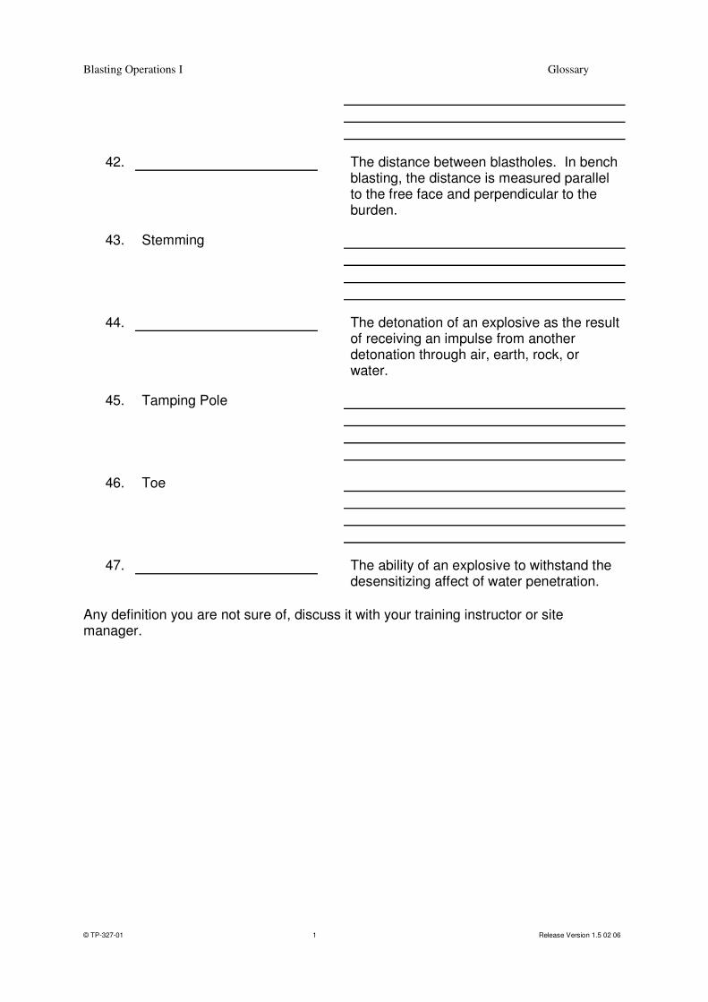
42.
The distance between blastholes. In bench blasting, the distance is measured parallel to the free face and perpendicular to the burden.
43. Stemming
44.
The detonation of an explosive as the result of receiving an impulse from another detonation through air, earth, rock, or water.
45. Tamping Pole
46. Toe
47.
The ability of an explosive to withstand the desensitizing affect of water penetration.
Any definition you are not sure of, discuss it with your training instructor or site manager.

Blasting Operations I Lightning Precautions
TP-327-02 1 Release Version 1.5 05/24/06
Blaster & Blaster’s Helper Competency Training
Subject: Lightning Precautions
Objectives: At the completion of this section you will be knowledgeable in:
� The hazard potential of lightning
� What to do if it occurs while loading explosives at a blast site. To achieve the objective, read through the following information then complete the exercise at the end of this section.

Blasting Operations I Lightning Precautions
TP-327-02 2 Release Version 1.5 05/24/06
Lightning Safety Safety is defined as the avoidance, correction or elimination of conditions, situations or activities that have a potential to cause an accident. For lightning, safety is avoidance of conditions that have the potential to cause an accident. Thunderstorms and lightning are two phenomenons, which have a direct cause and effect relationship. Lightning is a grave concern with regard to blasting operations. Lightning strikes are unpredictable, and can prematurely detonate both electric, electronic and nonelectric initiation systems and explosive materials. It is imperative that blasting operations be ceased upon the approach and progression of a thunderstorm, and the blast area cleared of personnel and secured until the storm has passed. Regulations: Mine Safety and Health Administration (MSHA) Both MSHA and OSHA have regulation standards a blaster must follow with respect to thunderstorm and lightning. MSHA has collected statistics from 1978 to 1985, which indicate that lightning caused 16 out of 80 premature detonations in mining. MSHA codifies blaster behavior in 30 CFR, Part 56.6604, "Precautions during storms". It states, "During the approach and progression of an electrical storm, all blasting operations shall be suspended and persons withdrawn from the blast area or to a safe location." The blast area, not to be confused with blast site, is defined as the area within the influence of flying material from the detonation of explosives. Persons include not only the blast crew, but also other miners inside the proposed blast area such as drillers, digging equipment operators, surveyors, etc. It is important to remember that MSHA regulations are considered to be minimum regulatory standards. Thunder, the audible event caused by lightning, can be heard by the human ear for a distance of typically about 10 miles. When you see a lightning flash, count 1001, 1002, 1003, 1004, and 1005, etc. until you hear the thunder. Sound travels at 1100 feet per second or approximately one mile for each 5 seconds at sea level. Therefore, if a person were to see a flash and subsequently 30 seconds later hear the thunder report, then the lightning was approximately 6 miles away (30 / 5 = 6). Heat lightning is a term used to describe lightning that is at such a distance, the thunder can't be heard. Environmental sounds and light conditions can drastically affect the distance at which the human ear and eye can perceive thunder and lightning. Regulations: Occupational Safety and Health Administration (OSHA) OSHA, which regulates the construction industry, has one regulation regarding blasting operations and electrical storms. 29 CFR, Subpart U "Blasting and the Use of Explosives", 1926.900 (k) states that "Due precautions shall be taken to prevent the accidental initiation of explosives from current induced by radar, radio transmitter, lightning, adjacent power lines, dust storms, or other extraneous sources of electricity.

Blasting Operations I Lightning Precautions
TP-327-02 3 Release Version 1.5 05/24/06
These precautions shall include the suspension of all blasting operations and the removal of all persons from the blast area during the approach and progression of an electric storm." This OSHA regulation is quite similar to the MSHA regulation. The word "Due" is a legal term meaning that every reasonable precaution should be taken. What to do - Prior to going to a blast site: Develop a rapid evacuation plan that is understood by all personnel that may be working at the blast site or in the blast area. Monitor the radio or TV for daily weather reports to determine the meteorological conditions for the proposed blasting location. What to do - While at the blast site: Monitor the sky conditions continuously during blasting operations. If the air suddenly cools, and the wind increases, look for a reason for the change. Use a lightning detection device to attain advanced warning of the approach of a thunderstorm or monitor an AM radio, tuned to an off broadcast frequency for electrical static interference. What to do - If conditions change: When you see a thunderstorm approaching -- evacuate the blast site. Ensure that the blast area is cleared of personnel and equipment, and guarded against reentry until after the thunderstorm subsides and atmospheric conditions indicate that it is safe to resume work. Be aware that the blast area could increase in size due to greater potential from flyrock from a partially loaded blast prematurely detonating. Time permitting, when blasting with electric detonators, open all electric circuit loops and leave individual detonator legwires shunted at the hole. If in imminent danger, leave the shot. If a lightning induced premature detonation occurs, refer to proper handling procedures under the misfire section. If you see a lightning flash, leave the blast site immediately! Stay in the truck during a thunderstorm or in a building. It is more dangerous to be outside. What to do - After the Storm has passed: Return to the blast site and resume blast loading.
Blasting Operations I Lightning Precautions
TP-327-02 4 Release Version 1.5 05/24/06
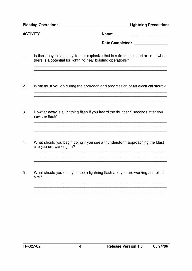
ACTIVITY Name: _________________________ Date Completed: ________________ 1. Is there any initiating system or explosive that is safe to use, load or tie-in when
there is a potential for lightning near blasting operations? _______________________________________________________________ _______________________________________________________________ _______________________________________________________________ 2. What must you do during the approach and progression of an electrical storm? _______________________________________________________________ _______________________________________________________________ _______________________________________________________________ 3. How far away is a lightning flash if you heard the thunder 5 seconds after you
saw the flash? _______________________________________________________________ _______________________________________________________________ _______________________________________________________________ 4. What should you begin doing if you see a thunderstorm approaching the blast
site you are working on? _______________________________________________________________ _______________________________________________________________ _______________________________________________________________ 5. What should you do if you see a lightning flash and you are working at a blast
site? _______________________________________________________________ _______________________________________________________________ _______________________________________________________________
Blasting Operations I Transportation on Bench
TP-327-03 1 Release Version 1.5 05/24/06
Blaster & Blaster’s Helper Competency Training
Subject: Transportation on Bench
Objectives: At the completion of this section you will be knowledgeable in:
� The hazard of operating a mobile piece of equipment at a blast
site � What precautions are required to work safely?
To achieve the objective, read through the following information, and then complete the exercise at the end of this section.
Blasting Operations I Transportation on Bench
TP-327-03 2 Release Version 1.5 05/24/06
Guidelines of Operation Explosive materials are normally delivered to the blast site by motor vehicle. The transportation route could be over the public highways, over private roadways (construction, quarry or mine sites) or a combination of these routes. Transportation over public highways is generally controlled by regulations of the Federal Department of Transportation found in 49 CFR. States, counties, and cities may have special rules regarding escort vehicles, approved routes, notification of delivery, etc. In the US, When transporting explosive materials over mining property (both surface and underground) the transportation should follow MSHA regulations prescribed in 30 CFR. Explosive materials hauled over general industry and construction sites are subject to OSHA regulations 29 CFR. In Canada Follow Federal, Provincial or Local regulations. More extensive skill training is provided for in TP #216 (HM126/HM161-USA & TDC- CAN) and respective truck operations TP #312, 313, 314, 318 and 319. When is it necessary to operate mobile equipment on the blast site, the blaster-in-charge or his designated helper shall closely control every movement and setup. All regulations shall be strictly followed (Federal, State, Provincial, Local). Extreme care must be taken to see that packaged explosives, initiation legwires, shock tubing, or detonating cord downlines are not run over or damaged by equipment or personnel. No vehicle is to be driven over loaded holes if another route of travel is available. For example, when blastholes are already loaded, place initiation downlines (legwire, shock tube, detonating cord) below the collar of the blasthole such that any vehicle or equipment shall not be driven over the initiation system in a manner, which could contact the system or create another hazard. This procedure may be allowed only where there is a written procedure for safely doing so. Only vehicles essential to, and directly involved in loading and stemming activities shall be allowed on the blast site and operated according to Orica safety standards and procedures for that equipment. TP #312, 313, 314, 318, 319). Nonessential vehicles are not allowed on the blast site. The driver of an essential vehicle should signal any move to other blast crew personnel. Automatic backup alarms must be on all essential vehicles. Whenever possible, it is recommended to load a shot so that essential vehicles can enter and exit the blast site without driving past loaded holes. If a vehicle is to be used within a blast site, the equipment operator must be assisted by a ground "spotter" to direct vehicle movement so as to avoid contacting any explosive material or initiation system with the vehicle and creating a hazard.
Blasting Operations I Transportation on Bench
TP-327-03 3 Release Version 1.5 05/24/06
ACTIVITY Name: _______________________________
Date Completed: ______________________ 1. Describe what vehicles are allowed within the blast site perimeter. ________________________________________________________________ ________________________________________________________________ ________________________________________________________________ ________________________________________________________________ 2. Automatic backup alarms must be on all vehicles essential to loading a blast. TRUE FALSE 3. If a vehicle is to be used within a blast site, the vehicle operator must be assisted
by a ground "spotter" to direct vehicle movement so as to avoid contacting any explosive material or initiation system with the vehicle and creating a hazard.
TRUE FALSE 4. No vehicle is to be driven over loaded blastholes if another route of travel is
available. TRUE FALSE 5. The blaster-in-charge or his designated helper shall closely control all movement
and setup of essential vehicles within the blast site perimeter. TRUE FALSE

Blasting Operations I Explosive Properties
TP-327-04 1 Release Version 1.5 05/24/06
Blaster & Blaster’s Helper Competency Training
Subject: Explosive Properties
� Water Resistance � Blasting Fumes
Objectives: At the completion of this section you will be knowledgeable in:
� An explosives' ability to detonate after its exposure to water � Blasting fumes and their hazard to people.
To achieve the objective, read through the following information, and then complete the exercise at the end of this section.

Blasting Operations I Explosive Properties
TP-327-04 2 Release Version 1.5 05/24/06
Water Resistance Many types of blasting applications involve explosives remaining in water filled blastholes for a long time. The water resistance of an explosive is defined as the product's ability to withstand water penetration without losing sensitivity or efficiency. It is generally expressed as the number of hours it may be submerged in static water and still be detonated reliably. When water penetrates an explosive product, it first impairs its efficiency and, with prolonged exposure or in severe water conditions, the explosive may be desensitized to such an extent that it does not detonate. The water resistance of a product depends not only on the packaging and the type of ingredients used in manufacturing, but also on the water conditions. Static water at low pressures will not affect the explosive as quickly as fast-moving water, at high pressure. The standard water resistance test is used primarily for rating of packaged dynamite explosives within one year from time of manufacture under good storage conditions. It consists of punching a number of holes in a cartridged product, immersing the sample in a vessel of water and then testing the sample with a No. 6 strength detonator for reliable detonation. The product is then rated with regard to its ability to withstand water degradation, according to the following:
Rating Hours Excellent 72 Good 24 Fair 8 Poor 1 Remember that this test is designed specifically for dynamite products When it comes to relative water resistance of various products:
� Non-gelatin dynamites have poor-to-good water resistance. � Gelatin dynamites and water gels explosives have good-to-excellent water
resistance. � Emulsion explosives have excellent water resistance. � ANFO has no water resistance.
� ANFO/emulsion blends have poor to excellent water resistance.

Blasting Operations I Explosive Properties
TP-327-04 3 Release Version 1.5 05/24/06
� Cast boosters made from various molecular explosives such as pentolite, PETN,TNT,RDX etc. have excellent resistance. Some boosters may contain ammonium nitrate mixtures added as a separate ingredient or as part of a combination demilitarized product. In these cases, the booster could have less resistance.
Blasting Fumes Fumes or gases (toxic and nontoxic) are produced as a normal byproduct of blasting operations, regardless of the type of explosive material used. The primary nontoxic fumes include: Oxygen (02), Nitrogen (N2), Carbon Dioxide (CO2), and water vapor (H20). Varying amounts of poisonous or toxic gases may also be produced; Carbon Monoxide (CO), Oxides of Nitrogen (N0x), and Hydrogen Sulphide (H2S). The emission of red/orange nitrogen oxide fumes from a blast indicates inefficient detonation. This could mean an incorrect formulation of ingredients that made the explosive, or more commonly signifies the need for a more water resistant explosive or package protection from water penetration or improper priming or lack of confinement, or inefficient detonation caused by product precompression before it detonates. ANFO, which is under fueled, will produce more NOx, as well as produce less energy than over fueled product. ANFO that is over fueled will produce more CO. Remember that CO is invisible. The best protection against toxic fumes is to stay out of the affected area until the all clear signal is sounded by the blaster-in-charge. IME FUME CLASSIFICATION
A classification indicating the amount of carbon monoxide and hydrogen sulfide produced by an explosive or blasting agent. Explosives with positive oxygen balances are not considered as being acceptable in these classifications. Amount of poisonous gases per 1 1/4'’ x 8'’ (32mm x 203mm) cartridge of explosive material. Fume Classification 1 Less than 0.16 cu. ft. (4.53 liters) 2 0.16 to 0.33 cu. ft. (4.52 to 9.35 liters)
3 0.33 to 0.67 cu. ft. (9.35 to 18.98 liters) In Canada Nox is included in Fume measurements.

Blasting Operations I Explosive Properties
TP-327-04 4 Release Version 1.5 05/24/06
Blasting Operations I Explosive Properties
TP-327-04 5 Release Version 1.5 05/24/06
ACTIVITY Name: _________________________ Date Completed: _________________ 1. What 3 factors affect an explosives ability to resist water degradation? ________________________________________________________________ ________________________________________________________________ ________________________________________________________________ 2. What is the water resistance rating for the listed hours of reliable detonation after
immersed in water for dynamite products? 72 ___________________________ 24 ___________________________ 8 ___________________________ 1 ___________________________ 3. What is the meaning of toxic blast fumes? ________________________________________________________________ ________________________________________________________________ ________________________________________________________________ 4. When is it safe to return to the blast site? ________________________________________________________________ ________________________________________________________________ ________________________________________________________________

Blasting Operations I Priming Explosives
TP-327-05 1 Release Version 1.5 05/24/06
Blaster & Blaster’s Helper Competency Training
Subject: Priming Explosives
� Assembly Make-Up � Location within Blasthole
Objective: At the completion of this section you will be able to:
� Make-up primers
� Place them in blastholes to be loaded with explosives.
To achieve the objective, read through the following information, and then complete the
exercise at the end of this section.

Blasting Operations I Priming Explosives
TP-327-05 2 Release Version 1.5 05/24/06
Priming Explosives A primer is a unit, package or cartridge of explosives used to initiate other explosives or blasting agents, and which contains a detonator, or detonating cord to which is attached a detonator designed to initiate the detonating cord. Remember, a primer contains an initiation device, a booster does not. Inadequately primed explosives will detonate at less than rated performance levels or could fail to detonate entirely. Even when the main explosive charge is adequately primed, overall blasting performance can still be affected by the primer's location. Assembly Make-up The make-up of the primer represents the initial stage in the blasting process where the detonation device and the main explosive charge come in contact with each other. For this reason, utmost care must be taken to perform this procedure properly. Primers must only be assembled at the blast site and only just prior to loading them into the blastholes. Care must be taken to ensure that the initiating device does not detach from the primer unit. Cast boosters have a pre-formed detonator well and/or detonating cord tunnel to achieve this requirement. The detonator is passed through the tunnel from the end opposite the detonator well so that the legwires/Exel tube passes through the tunnel before inserting the detonator completely into the pre-formed well (figure 1). When detonating cord is used with a cast booster, the cord is passed through the tunnel and a knot tied at the end of the cord to prevent the booster from falling off - subsequent boosters can then be slid down the detonating cord at required depths (figure 2). Ensure detonating cord is of adequate recommended core load when used to initiate a booster or cartridged explosive.
Figure 1 Figure 2

Blasting Operations I Priming Explosives
TP-327-05 3 Release Version 1.5 05/24/06
When priming a cartridge of emulsion, water gel or dynamite, a hole must be made centrally in the end of the cartridge with a clean non-sparking powder punch free of sand or grit. It must be deep enough to accept and completely enclose the detonator. It is essential that the detonator not be positioned to the outside of the cartridge or a misfire may result. The detonator should be located on the longitudinal axis and at one end of the primer cartridge. It should be attached so that it cannot be pulled out of position during loading. There should be no kinks or knots in the legwire or Exel tube, which might cause a break in the initiation system path. Electric or electronic detonators can be secured to a cartridge explosive by making 2 half hitches with the legwires around the cartridge. (figure 3) Half-hitching the lead wires around the primer cartridge is simple and fast, but has two disadvantages. 1. There is a danger of damaging the insulation (or even breaking the legwires) at the
half hitch if it is pulled up too tightly. 2. The half-hitch may slip off and the detonator may be pulled out of the cartridge if
the cartridge is loaded with the detonator pointing away from the collar of the blasthole.
Figure 3
Nonelectric detonators can be secured to a cartridge explosive by threading the Exel shock tube through or by taping the Exel shock tube to the cartridge. (figure 4)
Blasting Operations I Priming Explosives
TP-327-05 4 Release Version 1.5 05/24/06
Figure 4
When detonating cord is used with cartridged explosives, the cord should be secured with a tight knot, supplemented by half hitches around the cartridge or firmly attached to the cartridge with tape. After the primer is lowered into the blasthole to its desired location, the initiation system (detonating cord, legwires, Exel tube) lead should be secured to a wooden stake or rock near the blasthole collar. Blastholes that cannot be primed (blocked hole) shall be reported to the blaster-in-charge and the primer assembly taken apart before proceeding to the next blasthole. Location In general, primer location affects:
� movement of the rock mass during blasting � shearing of the rock mass at grade level � fragmentation of any cap rock in the stemming area
Bottom of the hole initiation provides a longer confinement of the expanding explosive gases and somewhat greater muckpile displacement than priming at the top of column. Exceptions to this rule may be at a coal mine, with a soft rock layer above the coal and a harder formation further up the column. In this example, the primer should be located in the harder rock formation. Bottom hole initiation also reduces the probability of blasthole cut-offs. Bottom priming in coal can cause coal damage. The blast geometry and rock hardness may dictate a particular priming location for best results. In general, blastholes are bottom-primed or multiple-primed, for the reasons listed below:
∗Top priming will produce early movement in the stemming and upper burden areas, premature gas venting and reduced explosion pressure in the toe region. This pressure drop is greatest for long charge lengths with insufficient stemming and small burden distances.

Blasting Operations I Priming Explosives
TP-327-05 5 Release Version 1.5 05/24/06
∗"Cut-offs" due to ground movement generally occur towards the top of the blasthole. In benching operations where sub-drill is required, locate the primer according to local recommendations. The overriding consideration must be that the primer is securely located in good, uncontaminated explosives. This generally means at a point somewhat above the bottom of the blasthole, to avoid burial in mud or drill cuttings. Where a particularly hard zone of rock exists, there may be a benefit from placing the primer within the hard zone to minimize energy loss into soft material. Under no circumstances should any attempt be made to free a "stuck" primer by pulling the legwires or shock tube as a premature explosion may result. If the primer cannot be pushed GENTLY forward, then it must remain where it is and reported to the blaster-in-charge. Primer cartridges should NEVER be slit, and care should always be taken in loading them. They should NOT be tamped but just lowered into position or pushed by means of an approved loading pole. Multiple Priming "Double-priming" (near the top and the bottom of the charge) is common practice in relatively long blastholes, to provide insurance against misfires. Law in certain areas also may require it. It is Orica’s recommendation to double prime all explosive charges over 30 ft. long. Multiple priming is recommended where there is perceived risk of ground movement, damage to downlines, groundwater dilution of explosives or contamination or separation of the in-hole charge. Multiple priming is effective for safety reasons as well as considerations of total hole cost. Multiple point priming is often required to avoid cut-off failures of the initiation system and explosive column or poor performance of the explosive because of loading problems, wet sections and pre-compression effects of adjacent blastholes. Where multiple primers are initiated in a blasthole using in-hole delay detonators, the use of the identical delay numbers will mean that approximately half the charges will initiate from top and half from the bottom. This is due to "scatter" in delay detonator firing times. If true bottom initiation is required, the top primer in each hole should contain a detonator delay, which is one number higher than that in the bottom primer. This makes the top primer an "insurance" unit only, and the entire explosives column should detonate before the top primer functions.

Blasting Operations I Priming Explosives
TP-327-05 6 Release Version 1.5 05/24/06
Deck Priming The major objective is to locate the primer in good uncontaminated explosives. This generally means at a point somewhat above or below the stemming material that is separating the explosive charges in the blasthole, to avoid burial in the drill cuttings, mud, or crushed stone.

Blasting Operations I Priming Explosives
TP-327-05 7 Release Version 1.5 05/24/06
ACTIVITY Name: __________________________ Date Completed: _________________ 1. Explain the difference between a primer and a booster: __________________________________________________________________ __________________________________________________________________ __________________________________________________________________ __________________________________________________________________ __________________________________________________________________ 2. When and where is it proper to make-up primer assemblies for use? __________________________________________________________________ __________________________________________________________________ __________________________________________________________________ __________________________________________________________________ __________________________________________________________________ 3. In benching operations, where sub-drill is required, describe where the primer should
be located and why? __________________________________________________________________ __________________________________________________________________ __________________________________________________________________ __________________________________________________________________ __________________________________________________________________ 4. If a primer should become "stuck" in a blasthole, what procedure is to be followed
by the person assigned to this job? __________________________________________________________________ __________________________________________________________________ __________________________________________________________________ __________________________________________________________________ __________________________________________________________________

Blasting Operations I Priming Explosives
TP-327-05 8 Release Version 1.5 05/24/06
5. What is Orica’s recommendation on multiple priming of an explosive charge? ______ __________________________________________________________________ __________________________________________________________________ __________________________________________________________________ __________________________________________________________________
Blasting Operations I Detonating Cord
TP–327-06 1 Release Version 1.5 05/24/06
Blaster & Blaster’s Helper Competency Training
Subject: Detonating Cord
� General Use � Tie in Proceedures
Objective: At the completion of this section you will be knowledgeable in:
� General use application � Recommended knotted connections for using detonating
cord at a blast site.
To achieve the objective, read through the following information, then complete the
exercise at the end of this section..

Blasting Operations I Detonating Cord
TP–327-06 2 Release Version 1.5 05/24/06
General Use Orica manufacturers a variety of detonating cords for initiating commercial explosives. When initiated, it detonates along its entire length at a velocity of approximately 23,000 feet per second (7,000 meters/second) and initiate any number of charges hooked up in a planned sequence to obtain the blasting results required. As a trunkline (18 gr/ft - 4g/m or larger) it will initiate any number of additional lengths, extensions or branch lines through the recommended knot connections. As a downline (9gr/ft - 1.9g/m or larger), it will either detonate all explosives in which it comes in contact or destroy a percentage of those explosives, which will reduce the effect of the explosives performance.
Basic Construction Detonating cord consists of two main components:
• Explosive Core: The center of detonating cord is an explosive known as PETN (pentaerythritoltetranitrate). For normal blasting applications, coreloads of 9 to 50 grains of explosive per foot (1.9 to 10.6 grams per meter) is standard. Once initiated, it explodes with great violence.
• Core Encasement: The PETN core is covered by a plastic tape surrounded by various combinations of textile yarns, plastics, and wax finishes. These provide the qualities required to satisfy various blasting applications for general use with commercial explosives. The difference between the several standard types of detonating cord is the degree of protection provided by the textile and plastic encasements.
Factory Splices The majority of the detonating cord Orica manufactures does not have any splices. However, when it is necessary to include a factory splice, the individual lengths are marked on the side of the spool and the outside of the case, (figure 1) so that splice locations are known and can be kept out of blastholes.
Blasting Operations I Detonating Cord
TP–327-06 3 Release Version 1.5 05/24/06
Cordtex 18 Spool and Case w/ Splice Markings
Figure 1
150
300
Orica uses three types of splices in manufacturing, depending on the coreload and the physical characteristics of the detonating cord. Square knot splice is used to join two lengths of flexible cord with a coreload (18 to 50 gr/ft) of sufficient power to shoot through the knotted connection.
Overlap Splice String Splice
Figure 2 Figure 3
Overlap splice is used to join two lengths of cord that are too stiff to join together with a square knot and of sufficient power to shoot through the lapped connection ( figure 2 ).
∗

Blasting Operations I Detonating Cord
TP–327-06 4 Release Version 1.5 05/24/06
String splice is used to join two lengths of cord with a coreload (less than 15 gr/ft) not of sufficient power to shoot through a knotted connection ( figure 3 ). WARNING: This type of detonating cord will not eliably initiate itself or other detonating cords through a knot connection.
Cutting Technique Orica detonating cords can be cut using a sharp knife or an anvil-type pruning shear. Never attempt to cut detonating cord with a blow from an axe, wrench or other object, or by sawing it; it may explode and cause injury or death. Never use scissor type (wire cutters) or diagonal (side-cut pliers). Initiation of Detonating Cord Orica detonating cord is designed to be initiated with an Exel Lead-in Line detonator, Exel T&D detonator, electric detonator or a safety fuse and cap assembly.
Figure 4Figure 5
Exel LIL w/ detonator Exel T&D
Figure 6
Electric Detonator
Detonating Cord
Electrical Tape
The Exel Lead-in Line detonator (figure 4) and Exel T&D detonator (figure 5) have as part of their assembly a plastic component for attaching the detonator to the detonating cord. The method of attaching either an electric detonator or safety fuse and cap assembly is to place either device alongside the detonating cord and wrap the cord and the detonator securely together with electrician's tape. (figure 6) Care should be taken to assure that the loaded or explosive end of the detonator is pointed in the direction the detonating cord is to detonate. This is very important, because of the directional affect of the detonator, initiation

Blasting Operations I Detonating Cord
TP–327-06 5 Release Version 1.5 05/24/06
may not occur in the reverse direction on the detonating cord. It is equally important that the core of the detonating cord be dry at the point of initiation.
If the coreload (PETN) of detonating cord becomes wet due to damage to the outside jacket or from end penetration of water, it cannot reliably be initiated by a detonator secured alongside the detonating cord or by a knotted connection. Initiating wet detonating cord is only reliable by: 1). end priming, or 2). using a high velocity booster, such as a Pentex AP or equivalent cast booster. (See Orica Detonating Cord Handbook for specific procedures of this method of initiation). Selecting Detonating Cord Type Detonating cord is available in a wide range of coreloads. The choice of which to use will depend on blasting conditions, method of initiation, what the detonating cord is to initiate and, the type of explosives used as the blasting charge.
• A wax finish with textile counterings (CordtexTM provide added abrasion resistance and knot-tying characteristics as compare to a plastic jacket detonating cord (B-LINE or TRUNKLINE).
• Higher coreload detonating cords generally have higher tensile strength and will withstand more abrasion abuse of ragged boreholes than smaller coreload detonating cords.
• All Orica detonating cords have similar resistance to end penetration from water and oil.
The function of detonating cord is to transport an initiation signal. Low coreload cords do this as well as higher coreload cords with less disruption of the explosive column. A general rule is to use the lowest coreload that will satisfy the required conditions. Detonating cords with coreloads 18 grains and greater per foot (3.6 grams per meter) will initiate themselves and other detonating cords through recommended knotted connections. AnolineTM and CordtexTM 7.5 and 15 can be initiated by any 18 grain per foot (3.6 grams per meter) or greater, but will not reliable initiate itself or any other detonating cord. Explosives vary in their sensitivity to the various types of detonating cords that Orica manufacturers. Consult the manufacturer's data/fact sheet of the explosive for compatibility with detonating cord for reliable initiation of that explosive.

Blasting Operations I Detonating Cord
TP–327-06 6 Release Version 1.5 05/24/06
Millisecond delay connectors and other nonelectric delay devices vary in their method of use and sensitivity. Consult the manufacturer's data/fact sheet for recommended minimum coreload detonating cord for reliable initiation of that explosive device. Loading Blastholes For ease of use, a spool holder that allows the detonating cord to unreel from the spool without twisting is the most convenient method of lowering a primer down a blasthole or extending a trunkline. After the primer is in position and before the loading of any explosives on top of the primer, the downline must be cut from the rest of the spool of cord. Allow at least three feet (one meter) of detonating cord to extend out of the blasthole for easier tying-in to the trunkline and to allow for some settling within the blasthole. The loose end of the detonating cord should be secured to a stick or other object at the blasthole collar to prevent it from being pulled down the hole and lost during loading. A single downline is usually adequate for most blasting applications. However, multiple downlines can be used in large diameter blastholes when adverse loading conditions exist. When more than one downline is used in a blasthole the downlines should be separated in the blasthole to minimize the adverse affect on the explosive column charge. It is Orica policy to avoid placing knots in a detonating cord downline whenever possible. However, there may be a condition that requires the blaster to extend the downline. When this is necessary, only a square knot connection should be used. The free end "tails" of each detonating cord section should be no less than 12 inches (30 cm) long to compensate for any end penetration of water or oil into the core of the cord and wrapped with tape to protect the knot during loading.
Downline and Trunkline Connections After all blastholes have been loaded, stemmed, and the blast site cleared of unnecessary equipment and personnel, the blast can be tied-in/hooked-up. When detonating cord is to be used as a trunkline, it should be unreeled so that it lies across the collar of each blasthole without creating any loops or kinks that would cause a misfire and laid out in a design plan so as to provide two paths of initiation to each blasthole to be tied-in. When it is necessary to extend a trunkline, the two pieces are connected together using a square knot.

Blasting Operations I Detonating Cord
TP–327-06 7 Release Version 1.5 05/24/06
1. Make a loop at the end of one of the pieces. 2. Insert the other end piece through the loop around and back through the
looped end. 3. Pull the knot tight. After the trunkline is in position over a blasthole collar, the downline can be attached using either of the recommend knots (clove hitch or double wrap clove
hitch) and that the knot forms a 90° angle of the downline to the trunkline to avoid angle cut-offs. (figure 7)
Figure 7 1. Make loop around the trunkline with downline. 2. Cross over 1st loop, and loop around trunkline 3. again bringing end under the cross over. 4. Pull knot tight. When tying-in multiple rows of blastholes, cross-ties of detonating cord trunklines should be utilized between rows to ensure blast design initiation sequence. The
recommended knotted connections (90° angle) is the same as for attaching downlines to trunklines. (figure 7)

Blasting Operations I Detonating Cord
TP–327-06 8 Release Version 1.5 05/24/06
Millisecond Delay Initiating The timing sequence for a detonating cord blast may be provided by: 1) Exel MS connectors in the trunkline. 2) Exel T&D units connected between downlines 3) Exel SHD or MS down the hole delays. The choice of the delay device or combination of delay devices for any blast will depend on local conditions and blast requirements.
ExelTM MS Connectors Millisecond delay connectors are used in trunkline hook- ups where Cordtex detonating cord is connected to both ends of the delay device. The MS connector accepts detonation from one end and initiates the detonating cord at the opposite end after the predetermined millisecond delay time. This delay device functions in two directions, and makes trunkline delay hook-ups simple and reliable to accomplish. (figure 8). See Exel initiation TP-327-7) for tie-in procedures.
Figure 8
ExelTM T&D Sometimes it is desirable to use detonating cord downlines in blastholes and eliminate the use of a trunkline. This can be done by attaching a Exel T&D to the downline of one blasthole and extend it to the next blasthole in the design sequence. This delay device functions in one direction only, and makes timing

Blasting Operations I Detonating Cord
TP–327-06 9 Release Version 1.5 05/24/06
designs less noisy and simple to accomplish. (figure 9) See Exel initiation (TP- 327-7) for tie-in procedures.
Figure 9
ExelTM SHD The advantage of using an in-hole delay with a detonating cord downline is to delay the detonation of the blasthole for a time period after the trunkline or Exel T&D network has functioned. This can be achieved by attaching an Exel SHD to the bottom of the downline with the recommended knot as the primer assembly is prepared for loading (figure 10). See Exel initiation (TP-327-7) for tie-in procedures.
Figure 10
Exel MS

Blasting Operations I Detonating Cord
TP–327-06 10 Release Version 1.5 05/24/06
The advantage of using an Exel MS in-hole delay with a detonating cord trunkline is to delay the detonation of the blasthole for a time period after the trunkline has functioned. In-addition the Exel tubing downline has the advantage of not disrupting the explosive column. The Exel tubing easily clips to the detonating cord trunkline at the blasthole collar for quick reliable hook-ups. (figure 14) See Exel initiation (TP-327-7) for tie-in procedures.
MS w/cord Figure 14

Blasting Operations I Detonating Cord
TP–327-06 11 Release Version 1.5 05/24/06
ACTIVITY Name: _________________________
Date Completed: ________________
1. Which of the following is one of the brand names for Orica detonating cord? a. Cordeau detonating fuse b. Cordtex c. Primacord 2. When initiated, detonating cord detonates at a velocity of approximately 23,000 ft/sec (7000 m/sec). a. True b. False 3. The core of general purpose detonating cord is which of the following explosives? a. PETN b. HMX c. TNT d. RDX 4. List the three types of factory splices that could be used on a spool of
detonating cord and the reason for using that type of splice by manufacturing.
5. Orica recommends which two tools for cutting detonating cord? a. __________________________ b. __________________________
Blasting Operations I Detonating Cord
TP–327-06 12 Release Version 1.5 05/24/06
6. Which of the following detonating cords should never be knotted together or used as a trunkline to initiate other detonating cords. a. Cordtex15 b. PRIMAFLEX c. POWERCORD 100 d. Cordtex 25 e. B-LINE f. Cordtex 7.5 g. Anoline 7. When initiating detonating cord with a detonator, what precaution must a individual be aware of before attaching the detonator to the detonating cord? ________________________________________________________________ _______________________________________________________________
________________________________________________________________ ________________________________________________________________ 8. If the coreload of detonating cord becomes wet due to damage to its outside jacket or from end penetration of water, which of the following methods are recommended for reliable initiation of the wet cord? a. End prime with a detonator b. Side prime with a detonator c. Use a high velocity booster d. Tie a big knot in the cord. 9. After a primer has been lowered into position in a blasthole on a detonating cord downline, what should the individual do before loading any explosives on top of the primer? ________________________________________________________________ ________________________________________________________________ ________________________________________________________________

Blasting Operations I Detonating Cord
TP–327-06 13 Release Version 1.5 05/24/06
10. Which type of knot is recommended when it is necessary to extend a trunkline of detonating cord? a. timber hitch knot b. square knot c. improved cinch knot d. stop knot 11. Which two types of knots are recommended for attaching a downline to a trunkline of detonating cord? a. ____________________________ b. ____________________________
12. The knot used to attached the downline to a trunkline at 90° is used to avoid what potential problem. ________________________________________________________________ ________________________________________________________________ ________________________________________________________________ 13. What are the two types of Orica nonelectric surface delay devices normally used with detonating cord? a. Exel MS Connectors b. Exel T&D c. Fuse and Cap assembly d. Exel SHD
Blasting Operations I Exel Initiation
TP-327-07 1 Release Version 1.5 05/24/06
Blaster & Blaster’s Helper Competency Training
Subject: ExelTM Initiation
� General Use Knowledge � Tying-In Procedures
Objective: At the completion of this section you will be knowledgeable in:
� General use applications of Exel initiation components normally
used in bench blasting. � Hookup / tying-in system components.
To achieve the objective, read through the following information then complete the exercise at the end of this section.

Blasting Operations I Exel Initiation
TP-327-07 2 Release Version 1.5 05/24/06
General Use Exel is the brand name of the Orica shock tube utilized in the manufacturing of its nonelectric detonator assemblies used for initiating commercial explosives. It can be described as a flexible, hollow tube that contains a thin layer of explosive. When initiated, a reaction occurs within the tube that produces a shock wave that propagates along the tubing at a velocity of 6600 feet per second (2000 meters/sec) to the detonator(s) attached to the end(s) of the tubing. As a surface delay detonator (HTD, T&D, Handidet
, MS Connector) it will initiate other Exel
shock tubes and/or detonating cords. HTD & Handidet will not initiate detonating cord trunklines/downlines. As an in-hole delay detonator (MS, SHD, LP, Handidet) it will initiate all detonator sensitive explosives when properly assembled as a primer. Basic Construction Exel shock tubing is a flexible abrasion resistant plastic tube that is coated internally with an even distribution of a very small quantity of HMX explosive and aluminum. Attached to the end is of the shock tubing is a delay detonator that functions as either an out-of-hole delay sequencing connector or a high strength in-hole delay detonator for priming explosives. Tying-in Procedures (SHD) Exel SHD is a short shock tube length delay detonator designed primarily for use within a blasthole in combination with a detonating cord downline. The SHD detonator can be attached to the end of a Cordtex 7.5 or Cordtex15 detonating cord downline (figure 1) or utilized in a sliding primer assembly (figure 2). Except for Exel SHD, all other Exel in-hole detonators (MS, LP, Handidet) do not require a tying-in procedure within the blasthole, because the shock tube is intended to extend from the collar of the blasthole in normal applications. To attach the Exel SHD shock tube to the end of a 7.5 or Cordtex 15 detonating cord downline requires tying a double wrap square knot (figure 1) with the detonating cord around the loop of Exel shock tube before making up the primer assembly and lowering it into the blasthole.

Blasting Operations I Exel Initiation
TP-327-07 3 Release Version 1.5 05/24/06
1. Insert the Cordtex detonating cord through the factory loop in the Exel shock tube, 2. Wrap the Cordtex around the shock tubing loop twice, 3. Insert the Cordtex back through the loop on the same side as it started, 4. Make knot tight. (figure 1)
Figure 1
When using Exel SHD detonators in slider primer applications, use only a cast booster specifically designed for this priming application. 1. Insert the Exel SHD detonator through the outside attached detonating cord tunnel, 2. Continue through the central tunnel of the booster, 3. Insert the SHD detonator in the boosters' detonator well, 4. Remove slack Exel tubing from primer assembly, 5. Insert Cordtex 15, 18 or 25 detonating cord downline through the outside slider tunnel, 6. Slide primer assembly down detonating cord downline with Exel SHD loop up. (figure 2)
Blasting Operations I Exel Initiation
TP-327-07 4 Release Version 1.5 05/24/06
Figure 2
Tying-in Procedures (Connectadet) Connectadet is a one-way trunkline and delay detonator assembly designed for use with Exel MS and Handidet detonators. After all blastholes have been loaded with explosives and stemmed, the tying-in procedure can begin. 1. At each blasthole place up to 6 Exel downline and surface delay shock tubes into the
plastic connector block (figure 3) of the incoming Connectadet unit, 2. Proceed with the outgoing Exel Connectadet to the next blasthole of the delay
sequence, 3. Repeat step 1 and 2.
Blasting Operations I Exel Initiation
TP-327-07 5 Release Version 1.5 05/24/06
Figure 3
Handidet is a combination one-way trunkline and delay with an in-hole detonator. After all blastholes have been loaded with explosives and stemmed, the tying-in procedure can begin. 1. At each blasthole, place up to 6 Exel downline and surface delay shock tubes into the
plastic connector block (figure 3) of the incoming Handidet unit, 2. Proceed with the outgoing Handidet surface delay connector block to the next
blasthole of the delay sequence (figure 4),
2. Repeat step 1 and 2.

Blasting Operations I Exel Initiation
TP-327-07 6 Release Version 1.5 05/24/06
Figure 4
Tying-in Procedures (T&D) Exel T&D is a one-way trunkline and delay detonator assembly designed for use with a Cordtex detonating cord downline or with Exel MS shock tube downlines. After all blastholes have been loaded with explosives and stemmed, the tying-in procedure can begin. · Detonating Cord Downline (Cordtex 15 or larger)
1. At each blasthole, place the detonating cord downline into the block connector of the incoming T&D unit so that the detonator points down the detonating cord,
2. Close and lock the hinged lid of the T&D block connector over the detonating cord,
3. Tie a knot in the tail end of the detonating cord to keep it from pulling loose from the
incoming T&D block connector,
4. Connect the outgoing T&D shock tube(s) to the detonating cord downline with the clip connector as close to the blasthole collar as possible,

Blasting Operations I Exel Initiation
TP-327-07 7 Release Version 1.5 05/24/06
5. Adjust and hold down the position of the outgoing shock tube(s) so that they
proceed straight away from the detonating cord and incoming T&D block connector for several feet (figure 5),
6. Cover the incoming T&D block connector with drill cuttings to eliminate shrapnel
cutoff of the outgoing Exel shock tubes,
7. Check tie-in to assure at least 12 inches is between the incoming T&D block connector and the outgoing Exel clip connection,
8. Repeat steps 1 thru 7.
1 7
B L A S T H O L E
O U T G O IN G T & D
IN C O M IN G T & D
C O R D T E X
D O W N L IN E
K N O T IN
D E T C O R D T A IL
F ig u re 5
NEVER allow the Exel shock tube to loop over or run adjacent to any detonating cord. NEVER place shock tube and detonating cord in the same T&D block connector. (figure 6)

Blasting Operations I Exel Initiation
TP-327-07 8 Release Version 1.5 05/24/06
Figure 6
Exel MS downline Tie-In
1. At each blasthole place up to 8 Exel MS shock tube downlines and outgoing
trunklines into the block connector of the incoming T&D unit so that the detonator points down the shock tubes,
2. Close and lock the hinged lid of the T&D block connector over the shock tubes,
3. Adjust and hold down the position of the Exel shock tube downline(s) and outgoing
trunkline(s) so that they proceed straight away from the T&D block connector for several feet (figure 7),
4. Cover the incoming T&D block connector with drill cuttings to eliminate shrapnel
cutoffs of the outgoing Exel shock tubes,
5. Proceed with the outgoing Exel T&D trunkline to the next blasthole of the delay sequence,
6. Repeat steps 1 thru 5.

Blasting Operations I Exel Initiation
TP-327-07 9 Release Version 1.5 05/24/06
Figure 7
NEVER attempt to initiate shock tube by tying or clipping it to another shock tube.
Exel MS Connector Exel MS Connector is a two-way delay detonator assembly designed for detonating cord trunklines (Cordtex 18 or larger coreload). After all blastholes have been loaded with explosives, stemmed and the downlines connected to the detonating cord trunkline, the placement and tie-in can begin. 1. Cut the detonating cord trunkline into two separate ends where the MS connector is to
be inserted into the trunkline, 2. Insert one of the detonating cord ends into one of the plastic connectors, 3. Wrap the "tail" of detonating cord around the top of the plastic connector twice so that
the cord clips under the retaining mechanism (figure 8),
4. Repeat the procedure with the other section of detonating cord trunkline in the other plastic connector.

Blasting Operations I Exel Initiation
TP-327-07 10 Release Version 1.5 05/24/06
Note: trim excess "tails" of detonating cord from lying across the Exel shock tube between the two plastic connectors.
Figure 8

Blasting Operations I Exel Initiation
TP-327-07 11 Release Version 1.5 05/24/06
ACTIVITY – 327-7 Name: _________________________
Date of Completion: ______________ 1. When initiated, Exel shock tubing detonates at what velocity?
________________________________________________________________ 2. What are the reactive materials that form the explosive dust inside an Exel shock
tube?
________________________________________________________________ ________________________________________________________________
3. What are the two reasons to cover Exel T&D connector blocks with drill cuttings?
________________________________________________________________ ________________________________________________________________ ________________________________________________________________ ________________________________________________________________
4. What is the maximum shock tube capacity of the Handidet or Exel HTD surface
delay connector block?
___________________________________ 5. What is the maximum shock tube capacity of the Exel T&D connector block?
___________________________________ 6. Which Exel initiation devices can be used with detonating cord?
________________________________________________________________ ________________________________________________________________ ________________________________________________________________ ________________________________________________________________

Blasting Operations I Exel Initiation
TP-327-07 12 Release Version 1.5 05/24/06
7. Which Exel initiation devices should never be used with detonating cord? _________________________________________________________________ ________________________________________________________________ ________________________________________________________________ ________________________________________________________________

Blasting Operations I Electric Initiation
TP - 327-08 1 Release Version 1.5 05/24/06
Blaster & Blaster’s Helper Competency Training
Subject: Electric Initiation
� General Use Knowledge � Blasting Wire Splices
� Test Instruments
Objective: At the completion of this section you will be knowledgeable in:
� General use application of an electric initiation system at
a bench blast site. � Making proper blasting circuit wire splices. � Electric blasting test instrument use.
To achieve the objective, read through the following information, and then complete the exercise at the end of this section.

Blasting Operations I Electric Initiation
TP - 327-08 2 Release Version 1.5 05/24/06
General Use
An electric initiation system utilizes an electrical power source with an associated circuit to convey the impulse to the electric detonators, which in turn fire and initiate the explosives charge. ElectricMS is the brand name of the Orica electric detonator normally utilized in bench blasting applications, in surface coal mines, open pit and underground mines, surface and underground quarries, and on construction projects.
Basic Construction Electrical energy flows from the power source through the circuit wiring to the electric detonator. Inside the electric detonator, the electrical energy is converted into heat energy by passing the firing current through a high-resistance bridgewire in the match head. (figure 1) The heat energy ignites the pyrotechnic that surrounds the bridgewire of the match assembly (Figure 1). The resulting flash or flame ignites the delay element. The delay composition then burns for a designated amount of time and ignites the primer charge, which then detonates the base charge. (figure 1) All Orica electric detonators have a static protection feature called static tape incorporated into the bridgewire assembly design. This static tape feature allows static energy to short across the assembly, thus protecting the bridgewire from that static energy and potential accidental detonation.
Figure 1

Blasting Operations I Electric Initiation
TP - 327-08 3 Release Version 1.5 05/24/06
ElectricMS electric detonators have nominal delay times for flexibility of blast design (figure 2).
E lec tric M S D eton ato rs
N om inal T im e D elay P eriod N om inal T im e D elay P eriod
MS MS
3 0 325 13
25 1 350 14
50 2 375 15
75 3 400 16
100 4 425 17
125 5 450 18
150 6 475 19
175 7 500 20
200 8 550 22
225 9 600 24
250 10 650 26
275 11 700 28
300 12 750 30
Nominal Delay Times (ms) Figure 2
Blasting Wire Splices The reliability of every circuit is dependent on the number and quality of the wire splices in the circuit. Their importance is very significant in the overall reliability of the circuit. These splices are easy to make and provide a strong and reliable connection. A. Small gauge wire to small gauge wire (legwire to legwire or connecting wire) (figure 3a)
1. Strip approximately 3 inches of insulation from each of the two wires that are to be spliced together,
2. Hold both bare wire ends together and fold the wires over to form a loop,
3. Twist the loop several times to create the splice.
Figure 3a

Blasting Operations I Electric Initiation
TP - 327-08 4 Release Version 1.5 05/24/06
B. Small gauge wire to heavy gauge wire (legwire or connecting wire to bus wire or firing line). (figure 3b)
1. Strip approximately 3 inches of insulation from the section of the bus wire to be spliced,
2. Wrap the small gauge wire twice around the bared bus wire,
3. Cross the small gauge wire over itself and wrap the bus wire several more
times in the reverse direction.
Figure 3b C. Small gauge wire to heavy gauge wire (legwire or connecting wire to firing line end: (figure 3c)
1. Strip approximately 4 inches of insulation from the ends of the small and heavy gauge wire,
2. Fold the heavy gauge wire over to form a hook,
3. Wrap the small gauge wire around the shank of the hook several times,
4. Cross over the bend of the hook with the small gauge wire,
5. Wrap the open end of the hook with the small gauge wire twice.

Blasting Operations I Electric Initiation
TP - 327-08 5 Release Version 1.5 05/24/06
Figure 3c
To prevent leakage or the shorting of a circuit between two wires, the bare wire at the splices should be insulated by supporting the splices in the air by propping up the wire splices and staggering their location so they cannot accidentally short the circuit between two splices. (figure 4)
Figure 4
Aluminum wire is not recommended for use in electric blasting circuits, since an aluminum oxide coating can form on the wire surface that will cause the contact resistance to increase.
Test Instruments Two types of electrical instruments are used for performing tests associated with electric blasting. These two electrical instruments are the Blasting Galvanometer and the Blaster's Multimeter. If the instrument does not say Blasting or Blaster's DO NOT USE IT. Blasting Galvanometer This instrument is a single or dual range blasting test instrument that can be used to make continuity checks and resistance measurements on a firing line, a single electric detonator, a detonator circuit and the complete blasting circuit. To make a measurement, touch the wire ends to the two terminals on the instrument and then read the resistance on the scale of the instrument face. (figure 5) Consult the manufacturers' instruction manual for an instrument's specific specifications.

Blasting Operations I Electric Initiation
TP - 327-08 6 Release Version 1.5 05/24/06
Figure 5 Blasters' Multimeter The Blaster's Multimeter is a multi purpose test instrument for making voltage and resistance measurements associated with electric blasting. A selector switch on the front of the instrument is turned to the desired voltage or resistance range and the measurement made is by attaching the two test leads that plug into the instrument to the wire ends. Each Blasters' Multimeter is provided with an instruction manual from the manufacturer that lists the instruments specifications and procedures for performing such tests as current leakage, stray current, and circuit resistance. For more information on these types of electrical tests and calculation of circuit resistance, see TP-329 electric initiation. (figure 6)

Blasting Operations I Electric Initiation
TP - 327-08 7 Release Version 1.5 05/24/06
Figure 6
Detonator Testing Procedure At the blast site the blaster or blaster's helper will only utilize a Blasting Galvanometer or Blaster's Multimeter to check for continuity of the electric detonator. This is done prior to stemming any blasthole charge containing an electric detonator. To make a continuity check of the electric detonator, place in contact the legwire ends to the two terminals on the Blasting Galvanometer or the two test leads of the Blaster's Multimeter and then read the resistance on the scale of the instrument face. This reading should correspond to the nominal resistance of the detonator (figure 7). If there is no measurement value or different from the nominal value of the detonator, then a problem exists that must be corrected before initiation.
Blasting Operations I Electric Initiation
TP - 327-08 8 Release Version 1.5 05/24/06
No. 10 .0999
No. 12 1.59
No. 14 2.53
N0. 16 4.02
No. 18 6.38
No. 20 10.15
8 2.5 1.94 3.2
12 3.5 2.11 3.9
16 4.5 2.28 4.6
24 7 2.61
30 9 2.40
40 12 2.66
60 18 3.19
Feet Meters Copper Iron
Legwire Length Nominal Resistance (ohms)
Resistance of Orica Detonators
AWG Ohms/1000 feet
Resistance of Copper Wire
Figure 7
Blasting Operations I Electric Initiation
TP - 327-08 9 Release Version 1.5 05/24/06
ACTIVITY Name: ________________________
Date Completed: ________________ ElectricMS 1. Inside the ElectricMS electric detonator, electric energy is converted into heat energy by passing the firing current through a high-resistance _____________? a. conversion wire b. bridgewire c. match head e. 20 AWG twinplex 2. What safety feature is utilized in Orica electric detonators to provide protection from static energy? a. the match head b. static tape c. static cup 3. How many nominal delay times are there for the ElectricMS electric detonator? a. 31 b. 26 c. 22 4. Insulated wires that extend out from an electric detonator are? a. connecting wire b. firing wires c. legwires 6. Is aluminum wire recommended for use in an electric blasting circuit? a. Yes b. No 7. What type of splice is used to connect a legwire to a legwire or connecting wire (wires of similar size)? a. twisted loop b. box twist

Blasting Operations I Electric Initiation
TP - 327-08 10 Release Version 1.5 05/24/06
c. flip and twist 8. What instrument measures for resistance and checks for continuity? a. Atlas TBS-5 b. Orica TBS-5 c. Blasting Galvanometer 9. What is the nominal delay time of an Electric MS #8 delay? a. 175 ms b. 200 ms c. 225 ms 10. To prevent current leakage or the shorting between two wires, the bare wire at the splices should be: a. insulated from ground by propping them up in air b. staggered, so the splices do not touch c. all the above 11. When should electric detonators be tested at the blast site?

Blasting Operations I Loading & Stemming Blastholes
TP-327-09 1 Release Version 1.5 05/24/06
Blaster & Blaster’s Helper Competency Training
Subject: Loading & Stemming Blastholes
Objectives: At the completion of this section you will knowledgeable in:
� Procedures to load blastholes with explosives and stemming. To achieve the objective, read through the following information, and then complete the exercise at the end of this section.

Blasting Operations I Loading & Stemming Blastholes
TP-327-09 2 Release Version 1.5 05/24/06
Loading and Stemming Procedures Tools normally required include: � Blasting Galvanometer or Blaster's Multimeter � Electronic blasting system control equipment � Nonmetallic measuring tape equipped with nonsparking weight � Burden Pole � Lowering rope with nonsparking hook � Nonsparking retrieving tools � Nonsparking powder punch � Tamping pole (s) � Nonsparking Orica approved safety knife � Mirror � Electrical tape � Connecting wire � Shovel � 5-gallon plastic bucket Before loading of blastholes all equipment not required for the loading operation should be moved off the blast site. Personnel on the blast site should be kept to a minimum and limited to the powder crew (or other authorized personnel familiar with the handling and use of explosive materials) who work under the direction of the blaster-in-charge. Before any explosive material is approved to be loaded into a blasthole, the blaster-in- charge must personally inspect the bench face for abnormalities, determine minimum face burden and toe burden of all open face blastholes, measure the bench height and review all blasthole depths, conditions, and any drilling logs for abnormal or unexpected conditions. The blaster-in-charge can assign to helpers how blastholes are to be loaded within the body of a blast. However, because blastholes along an open face have a greater potential for creating flyrock, the blaster-in-charge must directly supervise how each is to be loaded with explosives. Loading The primer is generally loaded first. However, when relatively small primers (1-5 lb) are used in large-diameter blastholes, it is recommended that a cartridge or a small amount of free-flowing explosive material be loaded into the blasthole before the primer to prevent the primer from being buried in drill cuttings or mud, and being separated from the main charge. After the primer has been loaded, the detonator leads should be anchored at the collar of the blasthole to a wooden stake or rock, providing enough tension to keep the leads
Blasting Operations I Loading & Stemming Blastholes
TP-327-09 3 Release Version 1.5 05/24/06
against the wall of the blasthole. If detonating cord is used, the cord should be cut from the spool and the loose end anchored at the collar of the blasthole, away from any explosive materials. The primer must be protected before dropping additional cartridges on top of it. This is done by lowering the first cartridge or by pouring a few feet of free- flowing explosive material on top of the primer. During loading, the explosive column should be checked with a measuring tape or loading pole to make sure that the powder rise is consistent and that the hole is not blocked or there are no openings where free-running explosive might be diverted to cause a concentrated buildup. To unknowingly load into one of these voids could cause blowouts or flyrock. Rotary drills normally produce smooth-walled, well-aligned blastholes that allow for easy loading of cartridged explosives and blasting agents. However, when blastholes are drilled through badly fractured strata, the result is often irregular walls, or when drilling through clay seams, the tendency is for the blasthole to squeeze and reduce the diameter. When loading cartridged materials in either of these conditions, it may be prudent to use a loading rope and lower the cartridges to prevent hang-ups. If a cartridge becomes lodged or stuck, it may be possible to dislodge or retrieve it with a lowering hook or a special retrieving hook. The cartridge might also be freed by bumping it with a tamping pole. Under no circumstances should any attempt be made to use a drill rod to push or drill through the cartridge of explosive materials. Drill steel, steel pipe, or a heavy weight is never to be used to dislodge cartridges. When emulsion or water gel explosives are dropped any distance onto water, they have a tendency to mushroom when they hit the water line. Generally, they will sink through the water if enough time is allowed before loading another cartridge. If mushrooming is a problem, it may be necessary to lower the cartridges to the water line before releasing them. In certain instances, due to lack of burden, weak material, crevices, clay seams, etc., the loading of a full column of explosive materials might result in overloading the blasthole and, that could produce air blast or flyrock. To achieve a more desirable and safer distribution of explosives in the blasthole, "deck loading" or the loading of alternated increments of explosive materials and inert stemming, allows for reducing the charge weight. The exact amount and location of each deck of explosive material and inert stemming must be determined and logged as it is loaded into the hole. Since each deck of explosive material is an independent charge separated from other charges by inert stemming, it is necessary that each explosive deck be primed. When a blasthole intersects a natural cavity in the rock, that area of the blasthole should be backfilled with inert stemming and the blasthole reprimed above the void before continuing the explosive loading process. For multiple priming under other conditions, see TP-327- 5. When wet blastholes cannot be dewatered, water resistant explosives must be used. When cartridge explosives are used to build the explosive column out of the water, it is necessary to "seal off" the water before changing over to a free-flowing explosive

Blasting Operations I Loading & Stemming Blastholes
TP-327-09 4 Release Version 1.5 05/24/06
(ANFO). Adequate tine should be allowed for a cartridge to sink and ensure coupling. To "seal" the last cartridge, the practice is to cut lengthwise one or two cartridges of emulsion and drop them on top of the last cartridge. This practice will prevent slumping of ANFO and ANFO/emulsion blends from sifting down into the water or water wicking up around the previously loaded cartridges and becoming desensitized. Sealing off with a cartridge is cost effective in preventing loss of ANFO and Nox generation. Stemming After all the blastholes have been loaded, the electric detonators, nonelectric system or electronic detonator downlines must be checked before any stemming is introduced into the blasthole. A blaster's galvanometer must be used to check the electric detonators.
An i-kon Logger or UNI Tronic network tester must be used to check the electronic detonators. Since a test instrument cannot be used to check nonelectric systems, these systems can be checked by visual inspection or by tugging lightly on the downlines to make sure that they have not been severed or damaged during the loading operation. If there is any evidence that the primer or initiating system has been damaged, a backup or "insurance" primer should be introduced to reprime the blasthole before stemming. (At some operations individual blastholes are stemmed as soon as they are loaded. When this practice is followed, the initiating system must be checked immediately after loading all explosives and before any stemming is placed in the blasthole.) Subsidence of the explosive column may cause excessive tension on the initiation system downlines. While stemming the blasthole, caution must be taken to assure that the legwires, Exel tube or detonating cord downlines are not damaged. Stemming material should be relatively clean, and free-flowing. Drill cuttings are not ideal for stemming, particularly in wet holes and in stemming decks in wet holes. Large rocks should be avoided since they may cut the legwires and downlines or bridge or choke in the blasthole. Empty cartridges, paper or plastic bags, powder boxes, or other types of combustible materials should not be used for stemming blastholes. After the blastholes are stemmed, the blaster-in-charge should make sure that all excess explosive materials and empty packaging materials (bags, boxes, etc.) are removed from the blast site. This should be done before the actual hookup of the blast starts to prevent damage by personnel walking over the blasting circuit. Unused explosives should be loaded in the powder truck and returned to the storage magazine. Empty packaging material should be disposed of or hauled to an authorized disposal area. Under no circumstance should the empty packaging material be burned on or near the blast site. Also, the packaging material should be checked before burning or disposal to make sure that there are no explosive materials in the packaging.

Blasting Operations I Loading & Stemming Blastholes
TP-327-09 5 Release Version 1.5 05/24/06
Activity Name: _________________________ Date Completed: ________________ 1. Before any explosive material is loaded into a blasthole, what should be
inspected, examined and determined. ________________________________________________________________ ________________________________________________________________ ________________________________________________________________ ________________________________________________________________ ________________________________________________________________ 2. How should the first cartridge of explosives (4 inch diameter & larger) be loaded
after the primer is placed at its proper location in the blasthole. ________________________________________________________________ ________________________________________________________________ ________________________________________________________________ ________________________________________________________________ ________________________________________________________________ 3 Explain the purpose of using a measuring tape or loading pole during the loading
of explosives into a blasthole. ________________________________________________________________ ________________________________________________________________ ________________________________________________________________ ________________________________________________________________ ________________________________________________________________ 4. When a blasthole intersects a void area in the rock, explain what should be done
to keep from overloading explosives. ________________________________________________________________ ________________________________________________________________ ________________________________________________________________ ________________________________________________________________ ________________________________________________________________

Blasting Operations I Loading & Stemming Blastholes
TP-327-09 6 Release Version 1.5 05/24/06
5. Explain the process of "sealing off" the water in a blasthole after loading the required amount of cartridge explosives.
________________________________________________________________ ________________________________________________________________ ________________________________________________________________ ________________________________________________________________ ________________________________________________________________ 6. What should be checked before stemming any loaded blasthole. ________________________________________________________________ ________________________________________________________________ ________________________________________________________________ ________________________________________________________________ ________________________________________________________________

Blasting Operations I Shot Calculations
TP-327-10 1 Release Version 1.5 05/24/06
Blaster & Blaster’s Helper Competency Training
Subject: Shot Calculations
� Explosive Charge Weights
Objectives: At the completion of this section you will be able to:
� Properly calculate weight of explosives per blasthole charge.
To achieve the objective, read through the following information, and then complete the exercise at the end of this section.

Blasting Operations I Shot Calculations
TP-327-10 2 Release Version 1.5 05/24/06
Explosives Distribution The distribution of explosives within a rock mass is one of the most important factors for successful blast results. When bulk explosives, such as Amex, emulsion/ANFO blends or Handi-Bulk are loaded to completely fill the cross section of the borehole, the explosives are referred to as being fully coupled to the borehole. When cartridge explosives are used, such as Magnum or Apex Ultra, they must be of smaller diameter than the borehole for ease of loading. Normally, the cartridge explosive diameter is 1 to 2 inches smaller than the borehole diameter, depending on borehole conditions (i.e., wet, fractured, muddy, etc.). In this instance, the explosive column is decoupled from the borehole walls. Calculating Explosive Column Weight The explosive column weight per borehole is a function of the density of the explosive, its diameter and the length of the column. If you are loading cartridge explosives, the column charge weight can be calculated by adding together the weight of each cartridge loaded. For example, if you load 5 cartridges of 3 X 16 inch Magnum Ultra into a blasthole, the charge weight is calculated as follows: Case Weight Magnum Ultra = 55 lbs. 3 x 16 inch cartridges per case = 16 Average cartridge weight = 55 lbs 16 ctgs = 3.4 lbs / ctg Explosive Charge WT = 5 ctgs / blasthole X 3.4 lbs / ctg = 24 lbs / blasthole If bulk explosive is being used, the explosive charge diameter is the same as the borehole, and the column charge weight can be calculated by using the following formula:

Blasting Operations I Shot Calculations
TP-327-10 3 Release Version 1.5 05/24/06
lbs/ft = 0.34 X (De)2 X d
0.34 = conversion factor De = explosive charge diameter (inches) d = explosive density This formula has been used to develop the following column loading table for determining Orica products charge weights. Explosives Column Load at a density of 1.0 g/cc
Explosives Column diameter
Explosives Load
Explosives Column
Diameter
Explosives Load
inches lb/ft inches lb/ft
3/4 7/8 1
1 1/8 1 1/4 1 3/8 1 1/2 1 5/8 1 3/4 1 7/8
2 2 1/4 2 1/2 2 3/4
3 3 1/4 3 1/2 3 3/4
4 4 1/4 4 1/2 4 3/4
5 5 1/4 5 1/2 5 3/4
6 6 1/4 6 1/2 6 3/4
7 7 1/4 7 1/2
0.19 0.26 0.34 0.43 0.53 0.64 0.77 0.90 1.04 1.20 1.36 1.72 2.13 2.57 3.06 3.59 4.17 4.78 5.44 6.14 6.89 7.67 8.50 9.37 10.29 11.24 12.24 13.28 14.37 15.49 16.66 17.87 19.13
7 3/4 8
8 1/4 8 1/2 8 3/4
9 9 1/4 9 1/2 9 3/4 10
10 1/4 10 1/2 10 3/4
11 11 1/4 11 1/2 11 3/4
12 12 1/4 12 1/2 12 3/4
13 13 1/2
14 14 1/2
15 15 1/2
16 17 18 20 22 24
20.42 21.76 23.14 24.57 26.03 27.54 29.09 30.69 32.32 34.00 35.72 37.49 39.29 41.14 43.03 44.97 46.94 48.96 51.02 53.13 55.27 57.46 61.97 66.64 71.49 76.50 81.69 87.04 98.26
110.16 136.00 164.56 195.84
Blasting Operations I Shot Calculations
TP-327-10 4 Release Version 1.5 05/24/06
Figure 1 Example: What is the explosive column loading factor for a 4 inch diameter borehole loaded with bulk explosive that has a product density of 1.0 g/cm
3 ?
Refer to Table 1; look for the explosive column diameter of 4 inches; then look to the right for the explosive column (lb/ft) loading factor. For this example, the answer is 5.44 lb/ft. If the same borehole is now loaded with explosives with a product density of 1.3 g/cm
3,
what is the explosive column loading factor ? 5.44 lb/ft X 1.3 = 7.07 lb/ft If the same borehole is now loaded with explosives with a product density of 0.84/cm
3,
what is the explosive column loading factor ? 5.44 lb/ft X 0.84 = 4.57 lb/ft These same answers can be calculated directly with the explosives column load formula used to develop table 1 (lbs/ft = 0.34 X (De)
2 X d ).
lb/ft = 0.34 x (4)
2 X 1.3 lb/ft = 0.34 x (4)
2 X 0.84
= 0.34 x 16 X 1.3 = 0.34 x 16 X 0.84 = 7.07 lb/ft = 4.57 lb/ft To calculate the total charge weight, multiply the loading factor by the height of the charge. Total Charge Weight = Loading Factor (lb/ft) X Height of Charge (ft) Example: If the explosive charge is 30 feet in length, the total charge weight would be calculated as follows: 7.07 lb/ft X 30 ft = 212.1 lbs 4.57 lb/ft X 30 ft = 137.1 lbs
Blasting Operations I Shot Calculations
TP-327-10 5 Release Version 1.5 05/24/06
In metric, the same principles apply but the calculation is simpler The formula for figuring kgs per meter of borehole is: Kg/m = 0.785 x de
x d
1000 Remember De is diameter of explosives in millimeters d is density of explosives in g/cc Given a 102 mm blasthole loaded with 8 meters of explosives at a density of .84 g/cc would load at 0.785 x 10²
2 x 0.84
1000 = 6860 1000 = 6.86 kgs per meter of borehole 6.86 meters x 8 meters = 54.88 kgs per hole or about 121 lbs per hole.

Blasting Operations I Shot Calculations
TP-327-10 6 Release Version 1.5 05/24/06
ACTIVITY Name: _________________________ Date Completed: ________________ 1. When bulk explosives are loaded into boreholes, the fully coupled explosive
charge diameter is the same as what? ________________________________________________________________ ________________________________________________________________ ________________________________________________________________ ________________________________________________________________ ________________________________________________________________ 2. What 3 factors must you know to calculate the charge weight of a bulk loaded
blasthole? ________________________________________________________________ ________________________________________________________________ ________________________________________________________________ ________________________________________________________________ ________________________________________________________________ 3. What is the cartridge weight of an explosive that has 10 cartridges per case that
weighs 55 lbs? ________________________________________________________________ ________________________________________________________________ ________________________________________________________________ ________________________________________________________________ ________________________________________________________________ 4. What is the charge weight of one (1) foot length, 5 inches diameter and a
product density of 1.0 g/cc? ________________________________________________________________ ________________________________________________________________ ________________________________________________________________ ________________________________________________________________ ________________________________________________________________

Blasting Operations I Shot Calculations
TP-327-10 7 Release Version 1.5 05/24/06
5. What is the charge weight of 20 foot length, 3.5 inches diameter and a product density of 1.25 g/cc?
________________________________________________________________ ________________________________________________________________ ________________________________________________________________ ________________________________________________________________ ________________________________________________________________ 6. What is the charge weight of 55 ft length, 12.25 inches diameter and a product
density of 0.85 g/cc? ________________________________________________________________ ________________________________________________________________ ________________________________________________________________ ________________________________________________________________ ________________________________________________________________

Blasting Operations I Vibration & Airblast
TP-327-11 1 Release Version 1. 05/24/06
Blaster & Blaster’s Helper Competency Training
Subject: Vibration & Airblast
� General Knowledge
� Seismograph Setup
Objectives: At the completion of this section you will be knowledgeable in:
� What creates blasting vibration and airblast. � How vibration and airblast waves travel. � How to setup a seismograph to record blasting vibration and airblast. To achieve the objective, read through the following information, and then complete the exercise at the end of this section.

Blasting Operations I Vibration & Airblast
TP-327-11 2 Release Version 1. 05/24/06
General Knowledge Blasting vibration and air blast are something the general public is aware of, but unfortunately, rarely understands. Even when exposed to low levels of vibration or air blast, the typical homeowner sometimes reacts by assuming that damage must be occurring to his or her property. These levels, however, must be extremely high and are not normally generated by controlled blasting. The federal government as well as many state and local governments have imposed blasting vibration limits of 2.0 inches per second (in/sec) peak particle velocity or less to prevent any type of damage to residential structures. Research conducted by the U.S. Bureau of Mines has revealed that normal activities around a home such as slamming a door can produce vibration levels as high as 1.3 in/sec, a person jumping can produce up to 1.8 in/sec, and just walking across the floor can produce vibration levels of up to 0.16 in/sec. Typical ground vibration levels produced by blasting, therefore, are no higher than what an average home is exposed to every day in the normal course of living activity. Always remember to take property owner concerns and complaints seriously. Public pressure can cause unrealistic blasting constraints to be imposed, or even total closure of an operation. Also, for seismograph recordings to be accepted as accurate, the instrument must be calibrated annually. How is Blasting Vibration Generated? When explosives are detonated in rock, energy is released. Most of this energy performs useful work such as breaking and heaving rock. Due to the elastic nature of all rocks, however, a small amount of this energy is absorbed by the rock and transmitted through the ground in the form of a seismic wave. Generally, if an explosive column is heavily confined, more energy is released in the form of ground vibration and less is available for breaking and heaving the rock. How Do Blasting Vibration Waves Travel? Two modes of seismic wave propagation have been identified. One is called a body wave that propagates through the earth. The other is called a surface wave that propagates along the surface of the earth following the contour of the land. Body and surface wave propagation are illustrated in Figure 1. Body waves radiate in a spherical pattern away from their source. Surface waves are generated whenever body waves reach the earth's surface. As a seismic wave travels outward from its source, ground particles become excited by the passing wave. These particles move back and forth ever so slightly, quickly returning back to their original rest position after the seismic wave passes. This particle motion caused by the passing seismic wave is called ground vibration and its magnitude is expressed as peak particle velocity in inches per second (in/sec) or millimeters per second (mm/sec). This can occur from a direct travel path from the source or can result from body waves reaching the surface after being reflected or refracted along joints, bedding planes or other discontinuities within the earth.

Blasting Operations I Vibration & Airblast
TP-327-11 3 Release Version 1. 05/24/06
Figure 1 How is Air Blast Generated? Another undesirable effect produced from blasting is that of air blast or air overpressure. Air blast is normally produced by the detonation of unconfined or under-confined explosives. While air blast rarely causes damage, its control is very important because high noise levels can be the basis for originating many blasting complaints. Air blast is defined as a temporary pressure pulse above the normal atmospheric pressure level. Air blast levels can be expressed in pounds per square inch (psi) or decibels (dB). (Figure 2 illustrates the correlation between psi and dB) Air blast that is audible is called noise while air blast at frequencies below 20 Hz is called concussion because it is inaudible to the human ear. Both audible and inaudible air blast have the potential to cause damage and generate homeowner complaints.
Figure 2

Blasting Operations I Vibration & Airblast
TP-327-11 4 Release Version 1. 05/24/06
How Do Air Blast Waves Travel? Air blast disturbances are propagated through the atmosphere via a compression wave and under certain weather conditions and poor blast design, can travel considerable distances. Air blast waves normally travel through the atmosphere at approximately 1,100 feet per second (335 meters per second), which is the typical speed of sound in air at sea level. Atmospheric conditions such as surface winds and temperature inversions can affect air blast travel considerably. Wind speed and direction can affect wave travel by focusing the air blast wave in the direction of the wind. Because wind speed is usually lower at ground level than higher in the atmosphere, the air blast wave can even be directed back to the earth's surface. A temperature inversion, which is defined as warmer air situated above cooler air, can also direct the air blast wave back toward the earth's surface. If the proper wind speed and direction and temperature inversion conditions are present at a blast site, their effects may combine to produce a high air blast focal point many miles away from the actual blast. This is often reported as a vibration complaint, when it is really the result of air blast focusing. Seismograph Recording Blasting vibration and air blast are measured in the field with a seismograph (Figure 3). Blasting seismographs utilize a geophone which contain three sensors arranged in mutually perpendicular directions to measure blasting vibration while air blast is measured with an attached microphone.
Figure 3

Blasting Operations I Vibration & Airblast
TP-327-11 5 Release Version 1. 05/24/06
Seismograph Set Up A more in depth discussion of proper seismograph setup is included in the Basic Course vibration and airblast section. The most important thing in blast monitoring is to allow an adequate amount of time to set up the seismograph properly. Do not be in a hurry. Missing seismic records are of no use should a regulatory agency request to see them or if litigation should arise. Care must be taken in choosing a proper location for the seismograph. In most instances the instrument must be located on the ground near the closest structure to the blast. Do not set the seismograph up near trees, fence lines, telephone poles, etc. since you will likely measure the response of these objects rather than the actual ground vibration wave. Be sure to coordinate with the blaster-in-charge the appropriate trigger levels for both air blast and ground vibration. Once the set up location is chosen, attach the geophone cable to the seismograph. Place the geophone firmly on the ground with the arrow pointing toward the direction of the blast and level it. It is extremely important that the geophone be properly coupled to the ground. If you can, bury, sandbag, or spike the geophone to ensure good coupling and to prevent erroneous movement. Do not, however, use a spike if you cannot push the spike completely into the ground. Next, attach the microphone cable to the seismograph. Point the microphone towards the direction of the blast. If it is extremely windy, place a windscreen over the microphone to prevent false triggers. Turn the instrument on and follow the instructions included with your seismograph for instrument set up. It is important that information such as date, time, seismograph location, distance to the blast, operator name, etc. are all properly entered during set up. Be specific on location and accurately measure distances from the recording location to the blast. Once the seismograph is set up and turned on, do not key any two-way radios near the instrument, since this may cause a false trigger of the seismograph and the potential to miss the blast event.

Blasting Operations I Vibration & Airblast
TP-327-11 6 Release Version 1. 05/24/06
ACTIVITY Name: _________________________ Date Completed: ________________ 1. Heavy confinement of an explosives column usually leads to: a. Better fragmentation b. Higher vibration levels c. Lower vibration levels 2. Typical ground vibration levels produced by blasting are higher than what an average home is exposed to every day in the normal course of living activity. a. True b. False 3. Particle velocity is typically expressed as: a. feet per second b. meters per second c. inches per second 4. Blasting seismographs measure which of the following: a. Air overpressure b. Velocity of detonation c. Particle motion 5. Air blast levels are expressed in: a. decibels b. Newtons c. inches per second 6. Air blast which is inaudible to the human ear (concussion) causes less damage than audible air blast (noise). a. True b. False
Blasting Operations I Vibration & Airblast
TP-327-11 7 Release Version 1. 05/24/06
7. What speed do air blast waves travel through the atmosphere at sea level? a. 1,100 meters per second b. 1,100 feet per second c. 1,100 inches per second 8. To obtain valid vibration readings, the seismograph's geophone should be placed where? a. In the house on the first floor b. In the house on the basement floor c. On the ground outside d. On the driveway if it is closest to the blast 9. Name two atmospheric conditions, which could cause focusing of the air blast wave and create a high overpressure reading. ___________________________________________________________________ ___________________________________________________________________ ___________________________________________________________________ ___________________________________________________________________ 10. When should you not attach the spike to the seismograph's geophone when setting the instrument up? __________________________________________________________________ __________________________________________________________________ __________________________________________________________________ __________________________________________________________________

Blasting Operations I Flyrock
TP-327-12 1 Release Version 1.5 05/24/06
Blaster & Blaster’s Helper Competency Training
Subject: Flyrock
� Awareness
Objectives: At the completion of this section you will be knowledgeable in:
� The hazards that flyrock can present and the items that must be considered when designing and loading a blast.
To achieve the objective, read through the following information, then complete to the exercise at the end of this section.

Blasting Operations I Flyrock
TP-327-12 2 Release Version 1.5 05/24/06
Flyrock Awareness Flyrock is rock that is propelled from a blast by explosives beyond the normal or expected safe blasting limits of the designated blast area. No other facet of blasting causes more damage to property and injury to people than flyrock. Therefore, only persons trained and experienced in the handling and use of explosive materials shall direct blasting operations and related activities. This responsibility is with the blaster-in-charge. He has the authority to supervise the blast crew on the decisions made at the blast site and the guarding of the blast. Trainees and inexperienced persons shall only work in the immediate presence of trained and experienced blast crew personnel. There are many factors the blast crew must consider when loading a blast as well as defining the blast area to be cleared of personnel and equipment. There is always going to be some movement of the material blasted. The type of geology and rock structure can contribute to situations that might increase the potential for flyrock. However, it is the human factors of judgement, training and experience that directly influence the decisions about explosives loading and blast design that prevents a flyrock occurrence. Figure 1 shows the area for normal rock movement during a blast. The blast crew must consider these zones plus the potential for unexpected rock movement. Rock traveling an excessive distance is not a flyrock hazard if the area is cleared beyond that potential distance. BLAST AREA = The area in which concussion, flying material or gases from an explosion may cause injury to persons or damage to property.
Figure 1

Blasting Operations I Flyrock
TP-327-12 3 Release Version 1.5 05/24/06
Flyrock awareness is taking precautions so as to avoid an accident. Every member of the blast crew and all appropriate customer personnel should be in agreement of the following before any blast is detonated: � Intended direction of blast movement,
� Shot firer location and type of protective shelter to be used by the personnel who will
detonate the blast, � Blast area boundary that must be cleared of all personnel and identified equipment, � Blast area guarding locations and the guard personnel assigned to control access to
the blast area, � The type and duration of the preblast, blast and all clear warning signals,
� Emergency plans in the event of an injury.
Flyrock safety is prevention of an occurrence. It is the application of procedures and practices that can be controlled and allowing an extra margin of safety for conditions that cannot be foreseen.

Blasting Operations I Flyrock
TP-327-12 4 Release Version 1.5 05/24/06
ACTIVITY Name: _________________________ Date Completed: _________________ 1. What is the major cause of all blasting related accidents? ________________________________________________________________ 2. Who has the responsibility, authority and liability of the loading, firing and
guarding a blast? ________________________________________________________________ 3. What are the six conditions that all blast crewmembers must be knowledgeable
of before any blast is detonated? ________________________________________________________________ ________________________________________________________________ ________________________________________________________________ ________________________________________________________________ ________________________________________________________________ ________________________________________________________________ ________________________________________________________________ ________________________________________________________________ ________________________________________________________________ ________________________________________________________________ ________________________________________________________________ ________________________________________________________________ ________________________________________________________________ ________________________________________________________________ ________________________________________________________________ ____________________________________________________________