tpe series 2000 - bbc pump and equipment company, inc. · grundfos tpe series 2000 pumps. the pumps...
TRANSCRIPT

GRUNDFOS INSTRUCTIONS
TPE Series 2000Installation and operating instructions

En
glis
h (U
S)
English (US) Installation and operating instructions
Original installation and operating instructions.
CONTENTSPage
1. Limited warrantyProducts manufactured by GRUNDFOS PUMPS CORPORATION (Grundfos) are warranted to the original user only to be free of defects in material and workmanship for a period of 24 months from date of installation, but not more than 30 months from date of manufacture. Grundfos' liability under this warranty shall be limited to repairing or replacing at Grundfos' option, without charge, F.O.B. Grundfos' factory or authorized service station, any product of Grundfos' manufacture. Grundfos will not be liable for any costs of removal, installation, transportation, or any other charges which may arise in connection with a warranty claim. Products which are sold but not manufactured by Grundfos are subject to the warranty provided by the manufacturer of said products and not by Grundfos' warranty. Grundfos will not be liable for damage or wear to products caused by abnormal operating conditions, accident, abuse, misuse, unauthorized alteration or repair, or if the product was not installed in accordance with Grundfos' printed installation and operating instructions.
To obtain service under this warranty, the defective product must be returned to the distributor or dealer of Grundfos' products from which it was purchased together with proof of purchase and installation date, failure date, and supporting installation data. Unless otherwise provided, the distributor or dealer will contact Grundfos or an authorized service station for instructions. Any defective product to be returned to Grundfos or a service station must be sent freight prepaid; documentation supporting the warranty claim and/or a Return Material Authorization must be included if so instructed.
GRUNDFOS WILL NOT BE LIABLE FOR ANY INCIDENTAL OR CONSEQUENTIAL DAMAGES, LOSSES, OR EXPENSES ARISING FROM INSTALLATION, USE, OR ANY OTHER CAUSES. THERE ARE NO EXPRESS OR IMPLIED WARRANTIES, INCLUDING MERCHANTABILITY OR FITNESS FOR A PARTICULAR PURPOSE, WHICH EXTEND BEYOND THOSE WARRANTIES DESCRIBED OR REFERRED TO ABOVE.
Some jurisdictions do not allow the exclusion or limitation of incidental or consequential damages and some jurisdictions do not allow limit actions on how long implied warranties may last. Therefore, the above limitations or exclusions may not apply to you. This warranty gives you specific legal rights and you may also have other rights which vary from jurisdiction to jurisdiction.
1. Limited warranty 2
2. Symbols used in this document 3
3. Abbreviations and definitions 3
4. General information 44.1 Radio communication 44.2 Battery 4
5. Mechanical installation 45.1 Mounting 45.2 Cable entries 45.3 Ensuring motor cooling 45.4 Outdoor installation 45.5 Drain holes 4
6. Electrical installation 56.1 Protection against electric shock, indirect contact 56.2 Mains supply 56.3 Additional protection 66.4 Connection terminals 76.5 Signal cables 96.6 Bus connection cable 9
7. Operating conditions 97.1 Maximum number of starts and stops 97.2 Ambient temperature 97.3 Installation altitude 107.4 Air humidity 107.5 Motor cooling 10
8. User interfaces 10
9. Advanced control panel 119.1 Menu structure 119.2 Menu overview for advanced control panel 12
10. Grundfos GO Remote 1410.1 Communication 1410.2 Menu overview for Grundfos GO Remote 15
11. Description of selected functions 1711.1 Setpoint 1711.2 Operating mode 1711.3 Set manual speed 1711.4 Control mode 1711.5 Analog inputs 1911.6 Pt100/1000 inputs 1911.7 Digital inputs 1911.8 Digital inputs/outputs 2011.9 Relay outputs 2011.10 Analog output 2011.11 Operating range 2111.12 Setpoint influence 2111.13 Communication 2211.14 General settings 22
12. Assist 2312.1 Setup of multi-pump system 23
13. Selection of control mode 24
14. Changing the position of the control panel 25
15. Bus signal 26
16. Priority of settings 26
17. Grundfos Eye 27
18. Signal relays 28
19. Megging 29
20. Technical data, single-phase motors 2920.1 Supply voltage 2920.2 Leakage current 29
21. Technical data, three-phase motors 2921.1 Supply voltage 2921.2 Leakage current 29
22. Inputs/outputs 29
23. Other technical data 3023.1 Torques 3023.2 Sound pressure level 30
24. Disposal 30
Warning
Prior to installation, read these installation and operating instructions. Installation and operation must comply with local regulations and accepted codes of good practice.
2
En
gli
sh
(U
S)
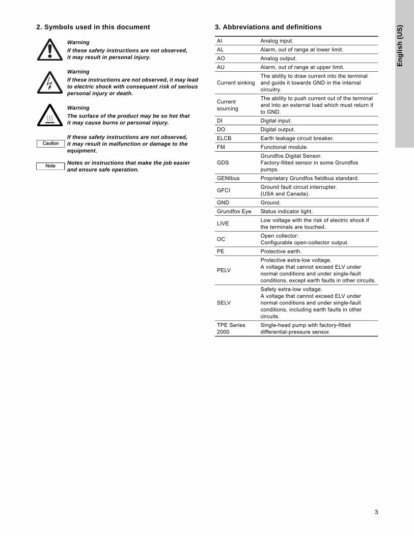
2. Symbols used in this document 3. Abbreviations and definitionsWarning
If these safety instructions are not observed, it may result in personal injury.
Warning
If these instructions are not observed, it may lead to electric shock with consequent risk of serious personal injury or death.
Warning
The surface of the product may be so hot that it may cause burns or personal injury.
CautionIf these safety instructions are not observed, it may result in malfunction or damage to the equipment.
NoteNote Notes or instructions that make the job easier and ensure safe operation.
AI Analog input.
AL Alarm, out of range at lower limit.
AO Analog output.
AU Alarm, out of range at upper limit.
Current sinkingThe ability to draw current into the terminal and guide it towards GND in the internal circuitry.
Current sourcing
The ability to push current out of the terminal and into an external load which must return it to GND.
DI Digital input.
DO Digital output.
ELCB Earth leakage circuit breaker.
FM Functional module.
GDSGrundfos Digital Sensor.Factory-fitted sensor in some Grundfos pumps.
GENIbus Proprietary Grundfos fieldbus standard.
GFCIGround fault circuit interrupter.(USA and Canada).
GND Ground.
Grundfos Eye Status indicator light.
LIVELow voltage with the risk of electric shock if the terminals are touched.
OCOpen collector:Configurable open-collector output.
PE Protective earth.
PELV
Protective extra-low voltage.A voltage that cannot exceed ELV under normal conditions and under single-fault conditions, except earth faults in other circuits.
SELV
Safety extra-low voltage.A voltage that cannot exceed ELV under normal conditions and under single-fault conditions, including earth faults in other circuits.
TPE Series 2000
Single-head pump with factory-fitted differential-pressure sensor.
3

En
glis
h (U
S)
4. General informationThese installation and operating instructions apply to the Grundfos TPE Series 2000 pumps.
The pumps are fitted with frequency-controlled permanent-magnet motors for single-phase or three-phase mains connection.
4.1 Radio communication
For installation in the USA and Canada, see also page 31.
This product can communicate with the Grundfos GO Remote and other products of the same type via the built-in radio module.
In some cases, an external antenna may be required. Only Grundfos-approved external antennas may be connected to this product, and only by a Grundfos-approved installer.
4.2 Battery
Pumps fitted with the advanced functional module (FM 300) incorporate a Li-ion battery. The Li-ion battery complies with the Battery Directive (2006/66/EC). The battery does not contain mercury, lead and cadmium.
5. Mechanical installation
5.1 Mounting
The pump must be secured to a solid foundation by bolts through the holes in the flange or the base plate.
5.2 Cable entries
The motor has four M20 screwed cable entries fitted with blind plugs from factory.
The following cable glands are included:
• 2 x M20 cable gland, cable diameter ∅0.016" (5 mm)• 1 x M20 cable gland, cable diameter ∅0.023 - 0.046"
(7-14 mm)
5.3 Ensuring motor cooling
Fig. 1 Minimum distance (D) from the motor to a wall or other fixed objects
5.4 Outdoor installation
When installed outdoors, the motor must be provided with a suitable cover to avoid condensation on the electronic components. See fig. 2.
The cover must be sufficiently large to ensure that the motor is not exposed to direct sunlight, rain or snow. Grundfos does not supply covers. We therefore recommend that you have a cover built for the specific application. In areas with high air humidity, we recommend that you enable the built-in standstill heating function.
Fig. 2 Examples of covers (not supplied by Grundfos)
5.5 Drain holes
When the motor is installed in moist surroundings or areas with high air humidity, the bottom drain hole should be open. The enclosure class of the motor will then be lower. The open drain hole helps prevent condensation in the motor as it will make the motor self-venting and allow water and humid air to escape.
The motor has a plugged drain hole on the drive side. The flange can be turned 90 ° to both sides or 180 °.
Fig. 3 Drain holes
Warning
Installation and operation must comply with local regulations and accepted codes of good practice.
NoteNoteIn order to maintain the UL mark, additional installation procedures must be followed. See page 31.
NoteNote
In order to ensure sufficient cooling of the motor, the distance (D) between the end of the fan cover and a wall or other fixed objects must always be at least 2.00" (50 mm), irrespective of motor size. See fig. 1.
TM
05
52
36
35
12
NoteNote When fitting a cover to the motor, observe the guideline in section 5.3 Ensuring motor cooling.
TM
05
79
19
16
13
TM
02
90
37
16
04
D
B3 B14 B5
4

En
gli
sh
(U
S)
6. Electrical installationCarry out the electrical connection according to local regulations.
Check that the supply voltage and frequency correspond to the values stated on the nameplate.
6.1 Protection against electric shock, indirect contact
Protective-earth conductors must always have a yellow/green (PE) or yellow/green/blue (PEN) color marking.
6.1.1 Protection against mains voltage transients
The motor is protected against mains voltage transients in accordance with EN 61800-3.
6.1.2 Motor protection
The motor requires no external motor protection. The motor incorporates thermal protection against slow overloading and blocking.
6.2 Mains supply
6.2.1 Single-phase supply voltage
• 1 x 200-240 V - 10 %/+ 10 %, 60 Hz, PE.
Check that the supply voltage and frequency correspond to the values stated on the nameplate.
The wires in the motor terminal box must be as short as possible. Excepted from this is the separated earth conductor which must be so long that it is the last one to be disconnected in case the cable is inadvertently pulled out of the cable entry.
For maximum backup fuse, see section 20.1 Supply voltage.
Fig. 4 Example of a mains-connected motor with mains switch, backup fuse and additional protection
Fig. 5 Mains connection, single-phase motors
Warning
Before making any connections in the terminal box, make sure that the power supply has been switched off for at least 5 minutes. Make sure that the power supply cannot be accidentally switched on.
The motor must be connected to an external all-pole mains switch according to local regulations.
The motor must be earthed and protected against indirect contact in accordance with local regulations.
If the power supply cable is damaged, it must be replaced by the manufacturer, the manufacturer's service partner or a similarly qualified person.
NoteNote
The user or the installer is responsible for the installation of correct earthing and protection according to local regulations. All operations must be carried out by a qualified electrician.
Warning
The motor must be earthed and protected against indirect contact in accordance with local regulations.
TM
05
40
34
19
12
TM
05
34
94
15
12
ELCB (GFCI)
5

En
glis
h (U
S)
6.2.2 Three-phase supply voltage
• 3 x 440-480 V - 10 %/+ 10 %, 60 Hz, PE.
Check that the supply voltage and frequency correspond to the values stated on the nameplate.
The wires in the motor terminal box must be as short as possible. Excepted from this is the separated earth conductor which must be so long that it is the last one to be disconnected in case the cable is inadvertently pulled out of the cable entry.
For maximum backup fuse, see section 21.1 Supply voltage.
Fig. 6 Example of a mains-connected motor with mains switch, backup fuses and additional protection
Fig. 7 Mains connection, three-phase motors
6.3 Additional protection
6.3.1 Single-phase motors
If the motor is connected to an electric installation where an earth leakage circuit breaker (ELCB) or ground fault circuit interrupter (GFCI) is used as additional protection, this circuit breaker or interrupter must be marked with the following symbol:
The leakage current of the motor can be found in section 20.2 Leakage current.
6.3.2 Three-phase motors
If the motor is connected to an electric installation where an earth leakage circuit breaker (ELCB) or ground fault circuit interrupter (GFCI) is used as additional protection, this circuit breaker or interrupter must be of the following type:
• It must be suitable for handling leakage currents and cutting-in with short pulse-shaped leakage.
• It must trip out when alternating fault currents and fault currents with DC content, i.e. pulsating DC and smooth DC fault currents, occur.
For these motors an earth leakage circuit breaker or ground fault circuit interrupter, type B, must be used. This circuit breaker or interrupter must be marked with the following symbols:
The leakage current of the motor can be found in section 21.2 Leakage current.
Protection against phase unbalance
The motor must be connected to a power supply with a quality corresponding to IEC 60146-1-1, class C, to ensure correct motor operation at phase unbalance.This also ensures long life of the components.
Caution
In order to avoid loose connections, ensure that the terminal block for L1, L2 and L3 is pressed home in its socket when the supply cable has been connected.
NoteNote Corner grounding is not allowed for supply voltages above 3 x 480 V, 60 Hz.
TM
05
39
42
18
12
TM
05
34
95
15
12
L1
L2
L3
L2
L1
L3
PE
ELCB (GFCI)
NoteNote
When an earth leakage circuit breaker or ground fault circuit interrupter is selected, the total leakage current of all the electrical equipment in the installation must be taken into account.
NoteNote
When an earth leakage circuit breaker or ground fault circuit interrupter is selected, the total leakage current of all the electrical equipment in the installation must be taken into account.
ELCB (GFCI)
ELCB (GFCI)
6

En
gli
sh
(U
S)
6.4 Connection terminalsThe descriptions and terminal overviews in this section apply to both single-phase and three-phase motors.
For maximum tightening torques, see section 23.1 Torques.
The number of terminals depends on the functional module (FM). The fitted module can be identified on the motor nameplate. See fig. 8.
Fig. 8 Identification of functional module
6.4.1 Connection terminals, advanced functional module (FM 300)
The advanced functional module is only available as an option.
The advanced module has these connections:
• three analog inputs
• one analog output
• two dedicated digital inputs
• two configurable digital inputs or open-collector outputs
• Grundfos Digital Sensor input and output*
• two Pt100/1000 inputs
• two LiqTec sensor inputs*
• two signal relay outputs
• GENIbus connection.
* Not applicable for TPE pumps.
See fig. 9.
• Inputs and outputsAll inputs and outputs are internally separated from the mains-conducting parts by reinforced insulation and galvanically separated from other circuits.All control terminals are supplied by safety extra-low voltage (SELV), thus ensuring protection against electric shock.
• Signal relay outputs
– Signal relay 1: LIVE:Mains supply voltages up to 250 VAC can be connected to this output.SELV:The output is galvanically separated from other circuits. Therefore, the supply voltage or safety extra-low voltage can be connected to the output as desired.
– Signal relay 2: SELV:The output is galvanically separated from other circuits. Therefore, the supply voltage or safety extra-low voltage can be connected to the output as desired.
• Mains supply (terminals N, PE, L or L1, L2, L3, PE).
A galvanically safe separation must fulfil the requirements for reinforced insulation including creepage distances and clearances specified in EN 61800-5-1.
TM
05
86
41
25
13
Env.Type : Serial no :
SF CL:PF:
PBFMHMIEff
n max:
CIMWgt :
DE :
kgNDE :
Tamb ::
F AA
V~
P.C. :
Made in Hungary
OUTPUT VARIANTINPUT
TEFC
Type :P.N. : U in :
I 1/1 :f in
Hp
Hz
P2
I SF Amp:
rpm: : :
:
::
:
Xxx
xxxx
xxxx
E.P
. Mot
or
DK - 8850 Bjerringbro, Denmark
Env.Tyype p :Serial no :
SF CL:PF:
Effn
Wggt :
DE :
kggNDE :
Tamb ::
F AA
V~
P.C. : INPUT
TEFC
Typype :P.N. : Uin :
I 1/1 :f in Hz
P
I SF Ampp::
PBFMHMICIM
VARIANTHp
rpm::
::
PB :
HMI:CIM :
Hprpm
NoteNote
Digital input 1 is factory-set to be start/stop input where open circuit will result in stop. A jumper has been factory-fitted between terminals 2 and 6. Remove the jumper if digital input 1 is to be used as external start/stop or any other external function.
NoteNote
As a precaution, the wires to be connected to the connection groups below must be separated from each other by reinforced insulation in their entire lengths.
7

En
glis
h (U
S)
* If an external supply source is used, there must be a connection to GND.
Fig. 9 Connection terminals, FM 300 (option)
TM
05
35
09
35
12
3
15
8
2623
25
24
7
21
20
22
B
Y
6
52
4
10
A
+24 V*
1
149
1217
19
11
18
+24 V* +
+24 V*OC DI
+24 V*/5 V*+24 V* +
+ ++24 V*/5 V*+24 V*
+24 V* + ++24 V*/5 V*+24 V*
+5 V* AI2
GDS RX
GDS TX
GND
GENIbus A
GENIbus B
+5 V
+24 V
+24 V
GND
GENIbus Y
GND
+5 VDI1
AI1
DI3/OC1
LiqTec
AI3
GND
DI2
LiqTec
GND
AOPt100/1000
Pt100/1000
DI4/OC2
GND
+24 V*OC DIGND
NC
C2
NO
NC
C1
NO
+5 V*
Terminal Type Function
NCNormally closed contact Signal relay 1
(LIVE or SELV)C1 Common
NO Normally open contact
NCNormally closed contact Signal relay 2
(SELV only)C2 Common
NO Normally open contact
18 GND Ground
11 DI4/OC2
Digital input/output, configurable.Open collector: Max. 24 V resistive or inductive.
19 Pt100/1000 input 2 Pt100/1000 sensor input
17 Pt100/1000 input 1 Pt100/1000 sensor input
12 AOAnalog output:0-20 mA / 4-20 mA0-10 V
9 GND Ground
14 AI3Analog input:0-20 mA / 4-20 mA0-10 V
1 DI2 Digital input, configurable
21 LiqTec sensor input 1LiqTec sensor input (white conductor)
20 GNDGround (brown and black conductors)
22 LiqTec sensor input 2LiqTec sensor input (blue conductor)
10 DI3/OC1
Digital input/output, configurable.Open collector: Max. 24 V resistive or inductive.
4 AI1Analog input:0-20 mA / 4-20 mA0.5 - 3.5 V / 0-5 V / 0-10 V
2 DI1 Digital input, configurable
5 +5 VSupply to potentiometer and sensor
6 GND Ground
A GENIbus, A GENIbus, A (+)
Y GENIbus, Y GENIbus, GND
B GENIbus, B GENIbus, B (-)
3 GND Ground
15 +24 V Supply
8 +24 V Supply
26 +5 VSupply to potentiometer and sensor
23 GND Ground
25 GDS TXGrundfos Digital Sensor output
24 GDS RX Grundfos Digital Sensor input
7 AI2Analog input:0-20 mA / 4-20 mA0.5 - 3.5 V / 0-5 V / 0-10 V
8

En
gli
sh
(U
S)
6.5 Signal cables• Use screened cables with a cross-sectional area of min. AWG 20 (0.5 mm2) and max. AWG 16 (1.5 mm2) for external on/off switch, digital inputs, setpoint and sensor signals.
• Connect the screens of the cables to frame at both ends with good connection. The screens must be as close as possible to the terminals. See fig. 10.
Fig. 10 Stripped cable with screen and wire connections
• Screws for frame connections must always be tightened whether a cable is fitted or not.
• The wires in the motor terminal box must be as short as possible.
6.6 Bus connection cable
6.6.1 New installations
For the bus connection, use a screened 3-core cable with a cross-sectional area of min. AWG 20 (0.5 mm2) and max. AWG 16 (1.5 mm2).
• If the motor is connected to a unit with a cable clamp which is identical to the one on the motor, connect the screen to this cable clamp.
• If the unit has no cable clamp as shown in fig. 11, leave the screen unconnected at this end.
Fig. 11 Connection with screened 3-core cable
6.6.2 Replacing an existing motor
• If a screened 2-core cable is used in the existing installation, connect the cable as shown in fig. 12.
Fig. 12 Connection with screened 2-core cable
• If a screened 3-core cable is used in the existing installation, follow the instructions in section 6.6.1 New installations.
7. Operating conditions
7.1 Maximum number of starts and stops
The number of starts and stops via the power supply must not exceed four times per hour.
When switched on via the power supply, the pump will start after approx. 5 seconds.
If a higher number of starts and stops is desired, use the input for external start/stop when starting/stopping the pump.
When started via an external on/off switch, the pump will start immediately.
7.2 Ambient temperature
7.2.1 Ambient temperature during storage and transportation
-22 - +140 °F (-30 - +60 °C).
7.2.2 Ambient temperature during operation
-4 - +122 °F (-20 - +50 °C).
The motor can operate with the rated power output (P2) at 122 °F (50 °C), but continuous operation at higher temperatures will reduce the expected product life. If the motor is to operate at ambient temperatures between 122 and 140 °F (50 and 60 °C), an oversized motor must be selected. Contact Grundfos for further information.
TM
02
13
25
44
02
T
M0
5 3
97
3 1
81
2T
M0
2 8
84
2 0
90
4
AYB
AYB
123
123
Motor
A
Y
B
A
Y
B
1
2
1
2
Motor
9

En
glis
h (U
S)
7.3 Installation altitude
Installation altitude is the height above sea level of the installation site.
• Motors installed up to 3281 ft (1000 m) above sea level can be loaded 100 %.
• Motors installed more than 3281 ft (1000 m) above sea level must not be fully loaded due to the low density and consequent low cooling effect of the air. See fig. 13.
Fig. 13 Derating of motor output power (P2) in relation to altitude above sea level
7.4 Air humidity
Maximum air humidity: 95 %.
If the air humidity is constantly high and above 85 %, one of the drain holes in the drive-end flange should be open. See section 5. Mechanical installation.
7.5 Motor cooling
To ensure cooling of motor and electronics, observe the following:
• Position the motor in such a way that adequate cooling is ensured. See section 5.3 Ensuring motor cooling.
• The temperature of the cooling air must not exceed 122 °F (50 °C).
• Keep cooling fins and fan blades clean.
8. User interfaces
Pump settings can be made by means of the following user interfaces:
• Standard control panel.See section 9. Advanced control panel.
• Grundfos GO Remote.See section 10. Grundfos GO Remote.
If the power supply to the pump is switched off, the settings will be stored.
Factory settings
TPE Series 2000 pumps have been factory-set to proportional-pressure control mode. See section 11.4.1 Proportional pressure.
Caution The motor must not be installed more than 6562 ft (2000 m) above sea level.
TM
05
64
00
-U.S
. 1
01
3
10.990.980.970.960.950.940.930.920.910.900.890.88
00
3281 3937 4593 5249 5906 6562 7218[ft]
P2[%]
Warning
The product may be so hot that only the buttons should be touched to avoid burns.
10

En
gli
sh
(U
S)
9. Advanced control panelThis control panel is fitted as standard on TPE Series 2000 pumps.
Fig. 14 Advanced control panel
9.1 Menu structure
The pump incorporates a start-up guide which is started at the first start-up. After the start-up guide, the four main menus will appear in the display.
1. Home
This menu shows up to four user-defined parameters with shortcuts or a graphical illustration of a Q/H performance curve.
2. StatusThis menu shows the status of the pump and system as well as warnings and alarms.
3. SettingsThis menu gives access to all setting parameters. A detailed setting of the pump can be made in this menu. See section 11. Description of selected functions.
4. AssistThis menu enables assisted pump setup, provides a short description of the control modes and offers fault advice. See section 12. Assist.
TM
05
48
49
10
13
Pos. Symbol Description
1
Grundfos EyeShows the operating status of the pump. See section 17. Grundfos Eye for further information.
2 - Graphical color display.
3 Goes one step back.
4
Navigates between main menus, displays and digits.When the menu is changed, the display will always show the top display of the new menu.
Navigates between submenus.
Saves changed values, resets alarms and expands the value field. Enables communication with the Grundfos GO Remote.
5
Makes the pump ready for operation/starts and stops the pump. Start: If the button is pressed when the pump is stopped, the pump will only start if no other functions with higher priority have been enabled. See section 16. Priority of settings.Stop: If the button is pressed when the pump is running, the pump will always be stopped. When the pump is stopped via this button, the "Stop" text next to the button will illuminate.
6 Goes to the "Home" menu.
1
2
3
4
5
6 NoteNote No settings can be made in this menu.
11

En
glis
h (U
S)
9.2 Menu overview for advanced control panel
9.2.1 Main menus
Home
Status
Operating statusOperating mode, fromControl mode
Pump performanceActual controlled valueResulting setpointSpeed
Power and energy consumptionMeasured values
Analog input 1Analog input 2Analog input 3Pt100/1000 input 1Pt100/1000 input 2
Analog outputWarning and alarm
Actual warning or alarmWarning logAlarm log
Operating logOperating hours
Fitted modulesDate and timeProduct identificationMotor bearing monitoringMulti-pump system
System operating statusSystem performanceSystem input power and energyPump 1, multi-pump systemPump 2, multi-pump systemPump 3, multi-pump system
12

En
gli
sh
(U
S)
Settings Section Page
Setpoint 11.1 Setpoint 17
Operating mode 11.2 Operating mode 17
Set manual speed 11.3 Set manual speed 17
Control mode 11.4 Control mode 17
Analog inputs 11.5 Analog inputs 19
Analog input 1, setupAnalog input 2, setupAnalog input 3, setup
Pt100/1000 inputs 11.6 Pt100/1000 inputs 19
Pt100/1000, setup
Digital inputs 11.7 Digital inputs 19
Digital input 1, setupDigital input 2, setup
Digital inputs/outputs 11.8 Digital inputs/outputs 20
Digital input/output 3, setupDigital input/output 4, setup
Relay outputs 11.9 Relay outputs 20
Relay output 1Relay output 2
Analog output 11.10 Analog output 20
Output signalFunction of analog output
Operating range 11.11 Operating range 21
Setpoint influence 11.12 Setpoint influence 21
External setpoint function 11.12.1 External setpoint influence 21
Predefined setpoints 11.12.2 Predefined setpoints 22
Monitoring functions 11.13 Communication 22
Motor bearing monitoringMotor bearing maintenanceStandstill heating
Communication 11.13 Communication 22
General settings 11.14 General settings 22
Assist Section Page
Assisted pump setupSetup, analog inputSetting of date and timeSetup of multi-pump system 12.1 Setup of multi-pump system 23
Description of control modeAssisted fault advice
13

En
glis
h (U
S)
10. Grundfos GO RemoteThe pump is designed for wireless radio or infrared communication with the Grundfos GO Remote.
The Grundfos GO Remote enables setting of functions and gives access to status overviews, technical product information and actual operating parameters.
The Grundfos GO Remote offers three different mobile interfaces (MI). See fig. 15.
Fig. 15 Grundfos GO Remote communicating with the pump via radio or infrared light
10.1 Communication
When the Grundfos GO Remote communicates with the pump, the indicator light in the middle of the Grundfos Eye will flash green. See section 17. Grundfos Eye.
Communication must be established using one of these communication types:
• radio communication
• infrared communication.
10.1.1 Radio communication
Radio communication can take place at distances up to 30 meters. It is necessary to enable communication by pressing
or on the pump control panel.
10.1.2 Infrared communication
When communicating via infrared light, the Grundfos GO Remote must be pointed at the pump control panel.
TM
06
07
33
111
4
Pos. Description
1
Grundfos MI 202:Add-on module which can be used in conjunction with Apple iPod touch 4G, iPhone 4G or 4GS.
Grundfos MI 204:Add-on module which can be used in conjunction with Apple iPod touch 5G or iPhone 5.
2
Grundfos MI 301:Separate module enabling radio or infrared communication. The module can be used in conjunction with an Android or iOS-based Smartphone with Bluetooth connection.
+
+
1
2
14

En
gli
sh
(U
S)
10.2 Menu overview for Grundfos GO Remote10.2.1 Main menus
Dashboard
Status
Resulting setpoint
Actual controlled value
Motor speed (rpm, %)
Power consumption
Energy consumption
Acc. flow, specific energy
Operating hours
Motor current
Number of starts
Pt100/1000 input 1
Pt100/1000 input 2
Analog output
Analog input 1
Analog input 2
Analog input 3
Digital input 1
Digital input 2
Digital input 3
Digital input 4
Fitted modules
15

En
glis
h (U
S)
Settings Section Page
Setpoint 11.1 Setpoint 17
Operating mode 11.2 Operating mode 17
Control mode 11.4 Control mode 17
Date and time
Buttons on product
Operating range 11.11 Operating range 21
Pump number 11.13.1 Pump number 22
Radio communication
Analog input 1
11.5 Analog inputs 19Analog input 2
Analog input 3
Pt100/1000 input 111.6 Pt100/1000 inputs 19
Pt100/1000 input 2
Digital input 111.7 Digital inputs 19
Digital input 2
Digital in/output 311.8 Digital inputs/outputs 20
Digital in/output 4
Analog output 11.10 Analog output 20
External setpoint funct. 11.12.1 External setpoint influence 21
Signal relay 111.9 Relay outputs 20
Signal relay 2
Standstill heating
Motor bearing monitoring
Service
Reset to factory settings
Store settings
Recall settings
Undo
Pump name
Unit configuration
Alarms and warnings
Alarm log
Warning log
"Reset alarm" button
Assist
Assisted pump setup
Assisted fault advice
Multi-pump setup
Product information
Product information
16

En
gli
sh
(U
S)
11. Description of selected functions11.1 SetpointThe setpoint for all control modes can be set in this submenu when the desired control mode has been selected. See section 11.4 Control mode.
11.2 Operating modePossible operating modes:
• NormalThe pump runs according to the selected control mode.
• StopThe pump stops.
• Min.The min. curve mode can be used in periods in which a minimum flow is required.
• Max.The max. curve mode can be used in periods in which a maximum flow is required. This operating mode is for instance suitable for systems with hot-water priority.
• ManualThe pump is operating at a manually set speed. See section 11.3 Set manual speed.
The pump can be set to operate according to the max. or min. curve, like an uncontrolled pump. See fig. 16.
Fig. 16 Max. and min. curves
11.3 Set manual speedThe pump speed can be set in %. When the operating mode has been set to "Manual", the pump will run at the set speed.
11.4 Control mode
Possible control modes:
• Prop. pressure (proportional pressure)
• Con. diff. press. (constant differential pressure)
• Const. curve (constant curve).
The setpoint for all control modes can be changed in the "Setpoint" submenu under "Settings" when the desired control mode has been selected.
11.4.1 Proportional pressure
The pump head is reduced at decreasing water demand and increased at rising water demand. See fig. 17.
This control mode is especially suitable in systems with relatively large pressure losses in the distribution pipes. The head of the pump will increase proportionally to the flow in the system to compensate for the large pressure losses in the distribution pipes.
The setpoint can be set with an accuracy of 0.33 ft. (0.1 m). The head against a closed valve is half the setpoint, Hset.
Fig. 17 Proportional pressure
This control mode requires a factory-fitted differential-pressure sensor as shown in the example below:
Fig. 18 Proportional pressure
TM
00
55
47
09
95
NoteNote The operating mode must be set to "Normal" before a control mode can be enabled.
Q
H
Max.
Min.
TM
05
79
09
16
13
Example
• Factory-fitted differential-pressure sensor.
H
Q
Hset
Hset2
p
17
En
glis
h (U
S)
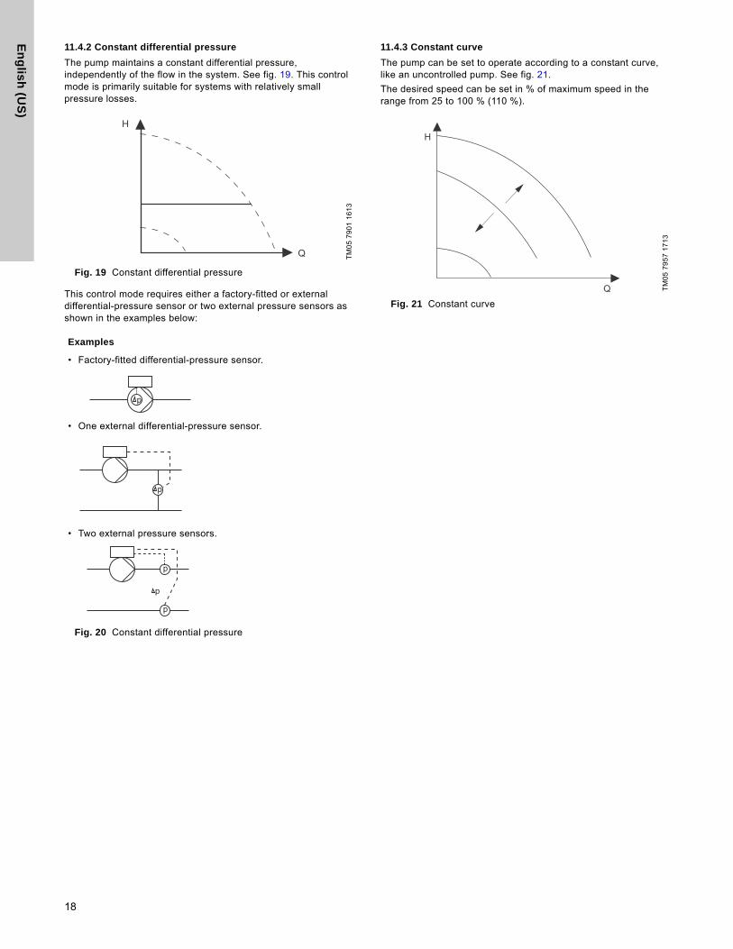
11.4.2 Constant differential pressure
The pump maintains a constant differential pressure, independently of the flow in the system. See fig. 19. This control mode is primarily suitable for systems with relatively small pressure losses.
Fig. 19 Constant differential pressure
This control mode requires either a factory-fitted or external differential-pressure sensor or two external pressure sensors as shown in the examples below:
Fig. 20 Constant differential pressure
11.4.3 Constant curve
The pump can be set to operate according to a constant curve, like an uncontrolled pump. See fig. 21.
The desired speed can be set in % of maximum speed in the range from 25 to 100 % (110 %).
Fig. 21 Constant curve
TM
05
79
01
16
13
Examples
• Factory-fitted differential-pressure sensor.
• One external differential-pressure sensor.
• Two external pressure sensors.
H
Q
p
p
p
p
p
TM
05
79
57
17
13
H
Q
18

En
gli
sh
(U
S)
11.5 Analog inputsAvailable inputs depending on the functional module fitted in the pump:
To set up an analog input, make the settings below.
Function
The analog inputs can be set to these functions:
• Not active• Feedback sensor• Ext. setpoint infl.
See section 11.12 Setpoint influence.
• Other function.
Measured parameter
Select one of the parameters, i.e. the parameter to be measured in the system by the sensor connected to the actual analog input.
Unit
Available measuring units:
Electrical signal
Select signal type (0.5 - 3.5 V, 0-5 V, 0-10 V, 0-20 mA or 4-20 mA).
Sensor range, min. value
Set the min. value of the connected sensor.
Sensor range, max. value
Set the max. value of the connected sensor.
11.6 Pt100/1000 inputsAvailable inputs depending on the functional module fitted in the pump:
Function
The Pt100/1000 inputs can be set to these functions:
• Not active• Feedback sensor• Ext. setpoint infl.
See section 11.12 Setpoint influence.
• Other function.
Measured parameter
Select one of the parameters, i.e. the parameter to be measured in the system.
11.7 Digital inputsAvailable inputs depending on the functional module fitted in the pump:
To set up a digital input, make the settings below.
Function
Select one of these functions:
• Not activeWhen set to "Not active", the input has no function.
• External stopWhen the input is deactivated (open circuit), the pump will stop.
• Min. (min. speed)When the input is activated, the pump will run at the set min. speed.
• Max. (max. speed)When the input is activated, the pump will run at the set max. speed.
• External fault When the input is activated, a timer will be started. If the input is activated for more than 5 seconds, the pump will be stopped and a fault will be indicated.
• Alarm resettingWhen the input is activated, a possible fault indication will be reset.
• Dry runningWhen this function has been selected, lack of inlet pressure or water shortage can be detected.When lack of inlet pressure or water shortage (dry running) is detected, the pump will be stopped. The pump cannot restart as long as the input is activated.This requires the use of an accessory, such as these:
– a pressure switch installed on the suction side of the pump
– a float switch installed on the suction side of the pump.
• Predefined setpoint digit 1 (applies only to digital input 2)When digital inputs are set to predefined setpoint, the pump will operate according to a setpoint based on the combination of the activated digital inputs.See section 11.12.2 Predefined setpoints.
The priority of the selected functions in relation to each other appears from section 16. Priority of settings.A stop command will always have the highest priority.
Function (terminal)FM 300
(advanced)
Analog input 1, setup (4) ●
Analog input 2, setup (7) ●
Analog input 3, setup (14) ●
Parameter Possible units
Pressure bar, m, kPa, psi, ft
Pump flow m3/h, l/s, yd3/h, gpm
Liquid temp. °C, °F
Other parameter %
Function (terminal)FM 300
(advanced)
Pt100/1000 input 1, setup (17 and 18) ●
Pt100/1000 input 2, setup (18 and 19) ●
Function (terminal)FM 300
(advanced)
Digital input 1, setup (2 and 6) ●
Digital input 2, setup (1 and 9) ●
19

En
glis
h (U
S)
11.8 Digital inputs/outputsAvailable inputs/outputs depending on the functional module fitted in the pump:
To set up a digital input/output, make the settings below.
Mode
The digital input/output 3 and 4 can be set to act as digital input or digital output:
• Digital input• Digital output.Function
The digital input/output 3 and 4 can be set to these functions:
Possible functions, digital input/output 3
Possible functions, digital input/output 4
11.9 Relay outputs
The pump incorporates two signal relays for potential-free signalling. See section 18. Signal relays for further information.
The signal relays can be configured to be activated by one of the following incidents:
• Ready• Operation• Alarm• Warning• Pump running• Control of external fan• Not active.
11.10 Analog outputWhether the analog output is available or not, depends on the functional module fitted in the pump:
To set up the analog output, make the settings below.
Output signal• 0-10 V• 0-20 mA• 4-20 mA.
Function of analog output• Actual speed• Actual value• Resulting setpoint• Motor load• Motor current.
Function (terminal)FM 300
(advanced)
Digital input/output 3, setup (10 and 16) ●
Digital input/output 4, setup (11 and 18) ●
Function if input Function if output
• Not active• External stop• Min.• Max.• External fault• Alarm resetting• Dry running• Predefined setpoint digit 2
• Not active• Ready• Alarm• Operation• Pump running• Warning
Function if input Function if output
• Not active• External stop• Min.• Max.• External fault• Alarm resetting• Dry running• Predefined setpoint digit 3
• Not active• Ready• Alarm• Operation• Pump running• Warning
Function (terminal)FM 300
(advanced)
Relay output 1 (NC, C1, NO) ●
Relay output 2 (NC, C2, NO) ●
Function (terminal)FM 300
(advanced)
Analog output ●
20

En
gli
sh
(U
S)
11.11 Operating rangeSet the operating range as follows:
• Set the min. speed within the range from fixed min. speed to user-set max. speed.
• Set the max. speed within the range from user-set min. speed to fixed max. speed.
The range between the user-set min. and max. speeds is the operating range. See fig. 22.
Fig. 22 Example of min. and max. settings
11.12 Setpoint influence11.12.1 External setpoint influence
It is possible to influence the setpoint by an external signal, either via one of the analog inputs or, if an advanced functional module is fitted, via one of the Pt100/1000 inputs.
If more than one input has been set up for setpoint influence, the function will select the analog input with the lowest number, for example "Analog input 2", and ignore the other inputs, for example "Analog input 3" or "Pt100/1000 input 1".
Example
See fig. 23.
At a lower sensor value of 0 psi, a set setpoint of 29 psi and an external setpoint of 60 %, the actual setpoint is 0.60 x (29 - 0) + 0 = 17.4 psi.
Actual setpoint = actual input signal x (setpoint - lower value) + lower value.
Fig. 23 Example of setpoint influence
NoteNote Speeds below 25 % may result in noise from the shaft seal.
TM
00
67
85
50
95
NoteNote
Before the "Digital inputs" can be enabled, one of the analog inputs or Pt100/1000 inputs must be set to "External setpoint function".
See sections 11.5 Analog inputs and 11.6 Pt100/1000 inputs.
Max. speed (fixed)
User-set max. speed
Operating range
User-set min. speed
Min. speed (fixed)
24 %
12 %
0 %
67 %
100 % (110 %)
TM
06
08
54
10
14
100
0
0 100
0
17.4
29
[PSI]
Setpoint influence [%]
External setpoint signal [%]
Actual input signal
Actual setpoint
Setpoint
Upper value
Lower value
21

En
glis
h (U
S)
Types of setpoint influence
• Not active• Linear function• Linear with Min.These functions can be selected:
• Not activeWhen set to "Not active", the setpoint will not be influenced from any external function.
• Linear functionThe setpoint is influenced linearly from 0 to 100 %. See fig. 24.
Fig. 24 Linear function
– Linear with Min.In the input signal range from 20 to 100 %, the setpoint is influenced linearly. If the input signal is below 10 %, the pump will change to operating mode "Min.". If the input signal is increased above 15 %, the operating mode will be changed back to "Normal". See fig. 25.
Fig. 25 Linear with Min.
11.12.2 Predefined setpoints
Seven predefined setpoints can be set and activated by combining the input signals to digital inputs 2, 3 and 4 as shown in the table below.
11.13 Communication11.13.1 Pump numberA unique number can be allocated to the pump. This makes it possible to distinguish between pumps in connection with bus communication.
11.14 General settings11.14.1 LanguageA number of languages are available.
Measuring units are automatically changed according to selected language.
TM
05
62
80
46
12
TM
05
62
81
46
12
100
010020 40 60 80
Setpoint influence [%]
External input [%]
100
010020 40 60 80
Setpoint influence [%]
External input [%]
Normal
Min.
Digital inputsSetpoint
2 3 4
0 0 0 Normal setpoint
1 0 0 Predefined setpoint 1
0 1 0 Predefined setpoint 2
1 1 0 Predefined setpoint 3
0 0 1 Predefined setpoint 4
1 0 1 Predefined setpoint 5
0 1 1 Predefined setpoint 6
1 1 1 Predefined setpoint 7
22

En
gli
sh
(U
S)
12. Assist12.1 Setup of multi-pump systemThe multi-pump function enables the control of pumps connected in parallel pumps without the use of external controllers. The pumps in a multi-pump system communicate with each other via the wireless GENIair connection or the wired GENI connection.
A multi-pump system is set up via a selected pump, i.e. the master pump (first selected pump). All Grundfos pumps with a wireless GENIair connection can be connected to the multi-pump system.
The multi-pump functions are described in the following sections.
12.1.1 Alternating operation
Only one pump is operating at a time. The change from one pump to the other depends on time or energy. If a pump fails, the other pump will take over automatically.
Pump system:
• Two pumps connected in parallel. The pumps must be of the same type and size. Each pump requires a non-return valve in series with the pump.
12.1.2 Back-up operation
One pump is operating continuously. The back-up pump is operated at intervals to prevent seizing up. If the duty pump stops due to a fault, the back-up pump will start automatically.
Pump system:
• Two pumps connected in parallel. The pumps must be of the same type and size. Each pump requires a non-return valve in series with the pump.
12.1.3 Cascade operation
Cascade operation ensures that the pump performance is automatically adapted to the consumption by switching pumps on or off. The system thus runs as energy-efficiently as possible with a constant pressure and a limited number of pumps.
All pumps in operation will run at equal speed. Pump changeover is automatic and depends on energy, operating hours and fault.
Pump system:
• Two to four pumps connected in parallel. The pumps must be of the same type and size. Each pump requires a non-return valve in series with the pump. The control mode must be set to "Const. pressure", "Con. diff. press." or "Const. curve".
23

En
glis
h (U
S)
13. Selection of control mode
System application Select this control mode
In systems with relatively large pressure losses in the distribution pipes and in air-conditioning and cooling systems.
• Two-pipe heating systems with thermostatic valves
– very long distribution pipes
– strongly throttled pipe balancing valves
– differential-pressure regulators
– large pressure losses in those parts of the system through which the total quantity of water flows (for example boiler, heat exchanger and distribution pipe up to the first branching).
• Primary circuit pumps in systems with large pressure losses in the primary circuit.
• Air-conditioning systems with
– heat exchangers (fan coils)
– cooling ceilings
– cooling surfaces.
Proportional pressure
In systems with relatively small pressure losses in the distribution pipes.
• Two-pipe heating systems with thermostatic valves and
– dimensioned for natural circulation
– small pressure losses in those parts of the system through which the total quantity of water flows (for example boiler, heat exchanger and distribution pipe up to the first branching) or
– modified to a high differential temperature between flow pipe and return pipe (for example district heating).
• Underfloor heating systems with thermostatic valves.
• One-pipe heating systems with thermostatic valves or pipe balancing valves.
• Primary circuit pumps in systems with small pressure losses in the primary circuit.
Constant differential pressure
In systems with a fixed system characteristic.
Examples:
• one-pipe heating systems
• boiler shunts
• systems with three-way valves
• domestic hot-water circulation.
Constant temperature and constant differential temperature
If an external controller is installed, the pump is able to change from one constant curve to another, depending on the value of the external signal.
The pump can also be set to operate according to the max. or min. curve, like an uncontrolled pump:
• The max. curve mode can be used in periods in which a maximum flow is required. This operating mode is for instance suitable for systems with hot-water priority.
• The min. curve mode can be used in periods in which a minimum flow is required.
Constant curve
In systems with pumps operating in parallel.
The multi-pump function enables the control of single-head pumps connected in parallel (two to four pumps) and twin-head pumps without the use of external controllers. The pumps in a multi-pump system communicate with each other via the wireless GENIair connection or the wired GENI connection.
"Assist" menu"Setup of multi-pump system"
H
Q
Hset
Hset2
H
Q
H
Q
H
Q
24
En
gli
sh
(U
S)
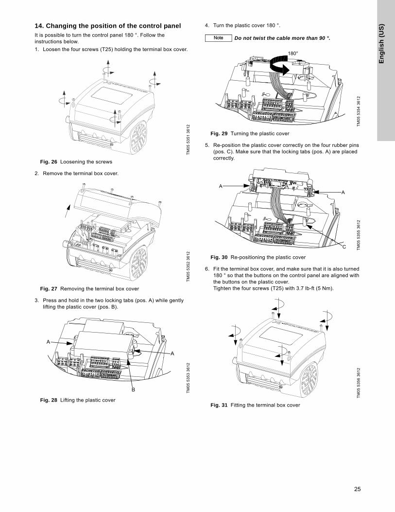
14. Changing the position of the control panelIt is possible to turn the control panel 180 °. Follow the instructions below.
1. Loosen the four screws (T25) holding the terminal box cover.
Fig. 26 Loosening the screws
2. Remove the terminal box cover.
Fig. 27 Removing the terminal box cover
3. Press and hold in the two locking tabs (pos. A) while gently lifting the plastic cover (pos. B).
Fig. 28 Lifting the plastic cover
4. Turn the plastic cover 180 °.
Fig. 29 Turning the plastic cover
5. Re-position the plastic cover correctly on the four rubber pins (pos. C). Make sure that the locking tabs (pos. A) are placed correctly.
Fig. 30 Re-positioning the plastic cover
6. Fit the terminal box cover, and make sure that it is also turned 180 ° so that the buttons on the control panel are aligned with the buttons on the plastic cover.Tighten the four screws (T25) with 3.7 lb-ft (5 Nm).
Fig. 31 Fitting the terminal box cover
TM
05
53
51
36
12
TM
05
53
52
36
12
TM
05
53
53
36
12
NoteNote Do not twist the cable more than 90 °.
TM
05
53
54
36
12
TM
05
53
55
36
12
TM
05
53
56
36
12
25

En
glis
h (U
S)
15. Bus signal The motor enables serial communication via an RS-485 input. The communication is carried out according to the Grundfos GENIbus protocol and enables connection to a building management system or another external control system.
Via a bus signal, it is possible to remote-set motor operating parameters, such as setpoint and operating mode. At the same time, the motor can, via the bus, provide status information about important parameters, such as actual value of control parameter, input power and fault indications.
Contact Grundfos for further information.
16. Priority of settings The motor can always be set to operation at max. speed or to stop with the Grundfos GO Remote.
If two or more functions are enabled at the same time, the motor will operate according to the function with the highest priority.
Example: If, via the digital input, the motor has been set to max. speed, the motor control panel or the Grundfos GO Remote can only set the motor to "Manual" or "Stop".
The priority of the settings appears from the table below:
* If the bus communication is interrupted, the motor will resume its previous operating mode, for example "Stop", selected on the motor control panel or with the Grundfos GO Remote.
NoteNoteIf a bus signal is used, the number of settings available via the Grundfos GO Remote will be reduced.
Priority Start/stop buttonControl panel on motor or
Grundfos GO RemoteDigital input Bus communication
1 Stop
2 Stop*
3 Manual
4 Max. speed*
5 Stop
6 Stop
7 Max. speed
8 Min. speed
9 Start
10 Max. speed
11 Min. speed
12 Min. speed
13 Start
14 Start
26

En
gli
sh
(U
S)
17. Grundfos EyeThe operating condition of the pump is indicated by the Grundfos Eye on the control panel. See fig. 32, pos. A.
Fig. 32 Grundfos Eye
TM
05
59
93
43
12
Grundfos Eye Indication Description
No lights on.Power off.Motor not running.
Two opposite green indicator lights rotating in the direction of rotation of the motor when seen from the non-drive end.
Power on.Motor running.
Two opposite green indicator lights permanently on.
Power on.Motor not running.
One yellow indicator light rotating in the direction of rotation of the motor when seen from the non-drive end.
Warning.Motor running.
One yellow indicator light permanently on.Warning.Motor stopped.
Two opposite red indicator lights flashing simultaneously.
Alarm.Motor stopped.
The green indicator light in the middle flashes quickly four times.
Remote control with the Grundfos GO Remote via radio.The motor is trying to communicate with the Grundfos GO Remote. The motor in question is highlighted in the Grundfos GO Remote display to inform the user of the location of the motor.
The green indicator light in the middle flashes continuously.
When the motor in question is selected in the Grundfos GO Remote menu, the green indicator light in the middle will flash continuously. Press on the motor control panel to allow remote control and data exchange via the Grundfos GO Remote.
The green indicator light in the middle is permanently on. Remote control with the Grundfos GO Remote via radio.
The motor is communicating with the Grundfos GO Remote via radio connection.
The green indicator light in the middle flashes quickly while the Grundfos Go Remote is exchanging data with the motor. It will take a few seconds.
Remote control with the Grundfos GO Remote via infrared light.The motor is receiving data from the Grundfos GO Remote via infrared communication.
A
27

En
glis
h (U
S)
18. Signal relaysThe motor has two outputs for potential-free signals via two internal relays.
The signal outputs can be set to "Operation", "Pump running", "Ready", "Alarm" and "Warning".
The functions of the two signal relays appear from the table below:
Description Grundfos Eye
Contact position for signal relays when activated
Operating modeOperation Pump
running Ready Alarm Warning
Power off.
Off
-
Pump running in "Normal" mode
Green, rotating
Normal, Min. or Max.
Pump running in "Manual" mode.
Green, rotating
Manual
Pump in operating mode "Stop".
Green, steady
Stop
Warning, but the pump is running.
Yellow, rotating
Normal, Min. or Max.
Warning, but the pump is running in "Manual" mode.
Yellow, rotating
Manual
Warning, but the pump was stopped via "Stop" command.
Yellow, steady
Stop
Alarm, but the pump is running.
Red, rotating
Normal, Min. or Max.
Alarm, but the pump is running in "Manual" mode.
Red, rotating
Manual
Pump stopped due to an alarm.
Red, flashing
Stop
NCNOC NCNOC NCNOC NCNOC NCNOC
C NO NC C NO NC C NO NC NCNOC NCNOC
C NO NC C NO NC NCNOC NCNOC NCNOC
NCNOC NCNOC C NO NC NCNOC NCNOC
C NO NC C NO NC C NO NC NCNOC C NO NC
C NO NC C NO NC NCNOC NCNOC C NO NC
NCNOC NCNOC C NO NC NCNOC C NO NC
C NO NC C NO NC NCNOC C NO NC NCNOC
C NO NC C NO NC NCNOC C NO NC NCNOC
NCNOC NCNOC NCNOC C NO NC NCNOC
28

En
gli
sh
(U
S)
19. Megging20. Technical data, single-phase motors
20.1 Supply voltage
• 1 x 200-240 V - 10 %/+ 10 %, 60 Hz, PE.
Check that the supply voltage and frequency correspond to the values stated on the nameplate.
Recommended fuse size
Standard as well as quick-blow or slow-blow fuses may be used.
20.2 Leakage current
Earth leakage current < 3.5 mA (AC supply).
Earth leakage current < 10 mA (DC supply).
The leakage currents are measured in accordance with EN 61800-5-1:2007.
21. Technical data, three-phase motors
21.1 Supply voltage
• 3 x 440-480 V - 10 %/+ 10 %, 60 Hz, PE.
Check that the supply voltage and frequency correspond to the values stated on the nameplate.
Recommended fuse size
Standard as well as quick-blow or slow-blow fuses may be used.
21.2 Leakage current
The leakage currents are measured in accordance with EN 61800-5-1:2007.
22. Inputs/outputs
Ground reference (GND)
All voltages refer to GND.
All currents return to GND.
Absolute maximum voltage and current limits
Exceeding the following electrical limits may result in severely reduced operating reliability and motor life:
Relay 1:
Maximum contact load: 250 VAC, 2 A or 30 VDC, 2 A.
Relay 2:
Maximum contact load: 30 VDC, 2 A.
GENI terminals: -5.5 to 9.0 VDC or < 25 mADC.
Other input/output terminals: -0.5 to 26 VDC or < 15 mADC.
Digital inputs (DI)
Internal pull-up current > 10 mA at Vi = 0 VDC.
Internal pull-up to 5 VDC (currentless for Vi > 5 VDC).
Certain low logic level: Vi < 1.5 VDC.
Certain high logic level: Vi > 3.0 VDC.
Hysteresis: No.
Screened cable: 20-16 AWG (0.5 - 1.5 mm2).
Maximum cable length: 1640 ft (500 m)
Open-collector digital outputs (OC)
Current sinking capability: 75 mADC, no current sourcing.
Load types: Resistive or/and inductive.
Low-state output voltage at 75 mADC: Max. 1.2 VDC.
Low-state output voltage at 10 mADC: Max. 0.6 VDC.
Overcurrent protection: Yes.
Screened cable: 20-16 AWG (0.5 - 1.5 mm2).
Maximum cable length: 1640 ft (500 m)
Analog inputs (AI)
Voltage signal ranges:
• 0.5 - 3.5 VDC, AL AU.
• 0-5 VDC, AU.
• 0-10 VDC, AU.
Voltage signal: Ri > 100 kΩ at 77 °F (+25 °C).
Leak currents may occur at high operating temperatures. Keep the source impedance low.
Current signal ranges:
• 0-20 mADC, AU.
• 4-20 mADC, AL AU.
Current signal: Ri = 292 Ω.
Current overload protection: Yes. Change to voltage signal.
Measurement tolerance: - 0/+ 3 % of full scale (max.-point coverage).
Screened cable: 20-16 AWG (0.5 - 1.5 mm2).
Maximum cable length: 1640 ft (500 m) (excl. potentiometer).
Potentiometer connected to +5 V, GND, any AI:
Use maximum 10 kΩ.
Maximum cable length: 328 ft (100 m).
CautionMegging of an installation incorporating MLE motors is not allowed, as the built-in electronics may be damaged.
Motor size[hp (kW)]
Min.[A]
Max.[A]
0.25 to 1.00 (0.12 to 0.75) 6 10
1.50 to 2.00 (1.1 to 1.5) 10 16
Motor size[hp (kW)]
Min.[A]
Max.[A]
0.25 to 1.50 (0.12 to 1.1) 6 6
2.00 to 3.00 (1.5 to 2.2) 6 10
Motor size[hp (kW)]
Leakage current[mA]
1.00 to 3.00 (0.75 to 2.2)(supply voltage < 400 V)
< 3.5
1.00 to 3.00 (0.75 to 2.2)(supply voltage > 400 V)
< 5
29

En
glis
h (U
S)
Analog output (AO)
Current sourcing capability only.
Voltage signal:
• Range: 0-10 VDC.
• Minimum load between AO and GND: 1 kΩ.
• Short-circuit protection: Yes.
Current signal:
• Ranges: 0-20 and 4-20 mADC.
• Maximum load between AO and GND: 500 Ω.
• Open-circuit protection: Yes.
Tolerance: - 0/+ 4 % of full scale (max-point coverage).
Screened cable: 20-16 AWG (0.5 - 1.5 mm2).
Maximum cable length: 1640 ft (500 m)
Pt100/1000 inputs (PT)
Temperature range:
• Minimum -22 °F (-30 °C) (88 Ω/882 Ω).
• Maximum 356 °F (+180 °C) (168 Ω/1685 Ω).
Measurement tolerance: ± 2.7 °F (1.5 °C).
Measurement resolution: < 0.54 °F (0.3 °C).
Automatic range detection (Pt100 or Pt1000): Yes.
Sensor fault alarm: Yes.
Screened cable: 20-16 AWG (0.5 - 1.5 mm2).
Use Pt100 for short wires.
Use Pt1000 for long wires.
LiqTec sensor inputs*
Use Grundfos LiqTec sensor only.
Screened cable: 20-16 AWG (0.5 - 1.5 mm2).
Power supplies (+5 V, +24 V)
+5 V:
• Output voltage: 5 VDC - 5 %/+ 5 %.
• Maximum current: 50 mADC (sourcing only).
• Overload protection: Yes.
+24 V:
• Output voltage: 24 VDC - 5 %/+ 5 %.
• Maximum current: 60 mADC (sourcing only).
• Overload protection: Yes.
Digital outputs (relays)
Potential-free changeover contacts.
Minimum contact load when in use: 5 VDC, 10 mA.
Screened cable: 20-12 AWG (0.5 - 2.5 mm2).
Maximum cable length: 1640 ft (500 m)
Bus input
Grundfos GENIbus protocol, RS-485.
Screened 3-core cable: 20-16 AWG (0.5 - 1.5 mm2).
Maximum cable length: 1640 ft (500 m)
23. Other technical data
EMC (electromagnetic compatibility)
EN 61800-3.
Residential areas, unlimited distribution, corresponding to CISPR 11, class B, group 1.
Industrial areas, unlimited distribution, corresponding to CISPR 11, class A, group 1.
Contact Grundfos for further information.
Enclosure class
Standard: IP55 (IEC 34-5).
Optional: IP66 (IEC 34-5).
Insulation class
F (IEC 85).
23.1 Torques
23.2 Sound pressure level
The grey fields indicate that the motor is not yet available in this MLE motor range, but is available in the previous MLE motor range.
24. DisposalThis product or parts of it must be disposed of in an environmentally sound way:
1. Use the public or private waste collection service.
2. If this is not possible, contact the nearest Grundfos company or service workshop.
The waste battery should be disposed of through the national collective schemes. If in doubt, contact your local Grundfos company.
Subject to alterations.
Terminal Thread sizeMax. torque[lbf-ft (Nm)]
L1, L2, L3, L, N M4 1.3 (1.8)
NC, C1, C2, NO M2.5 0.4 (0.5)
1 to 26 and A, Y, B M2 0.4 (0.5)
Motor[hp (kW)]
Max. speed stated on nameplate
[rpm]
Speed[rpm]
Sound pressure levelISO 3743[dB(A)]
1-phase motors
3-phase motors
0.25 to 1.00(0.12 to 0.75)
20001500 38 38
2000 42 42
40003000 53 53
4000 58 58
1.50(1.10)
20001500 38
2000 42
40003000 53 53
4000 58 58
2.00(1.50)
40003000 57 57
4000 64 64
3.00(2.20)
40003000 57
4000 64
30

Ap
pe
nd
ix
31
Appendix
1. Installation in the USA and Canada
1.1 Electrical codes
For USA
This product complies with the Canadian Electrical Code and the US National Electrical Code.
This product has been tested according to the national standards for Electronically Protected Motors:
CSA 22.2 100.04: 2009 (applies to Canada only).
UL 1004-1: June 2011 (applies to USA only).
Pour le Canada
Codes de l'électricité
Ce produit est conforme au Code canadien de l'électricité et au Code national de l'électricité américain.
Ce produit a été testé selon les normes nationales s'appliquant aux moteurs protégés électroniquement:
CSA 22.2 100.04: 2009 (s'applique au Canada uniquement).
UL 1004-1: Juin 2011 (s'applique aux États-Unis uniquement).
1.2 Radio communication
For USA
This device complies with part 15 of the FCC rules and RSS210 of IC rules.
Operation is subject to the following two conditions:
• This device may not cause interference.
• This device must accept any interference, including interference that may cause undesired operation of the device.
Pour le Canada
Communication radio
Ce dispositif est conforme à la partie 15 des règles de la FCC et aux normes RSS210 de l'IC.
Son fonctionnement est soumis aux deux conditions suivantes:
• Ce dispositif ne doit pas provoquer de brouillage préjudiciable.
• Il doit accepter tout brouillage reçu, y compris le brouillage pouvant entraîner un mauvais fonctionnement.
1.3 Identification numbers
For USA
Grundfos Holding A/S
Contains FCC ID: OG3-RADIOM01-2G4.
For Canada
Grundfos Holding A/S
Model: RADIOMODULE 2G4
Contains IC: 10447A-RA2G4M01.
Pour le Canada
Numéros d'identification
Grundfos Holding A/S
Modèle: RADIOMODULE 2G4
Contient IC: 10447A-RA2G4M01.
Location of identification numbers
Fig. 1 Identification numbers
Fig. 2 Identification numbers
1.4 Electrical connection
1.4.1 Conductors
Use 140/167 °F (60/75 °C) copper conductors only.
1.4.2 Torques
Maximum tightening torques for the terminals can be found in section Torques, page 30.
1.4.3 Line reactors
Maximum line reactor size must not exceed 1.5 mH.
1.4.4 Fuse size/circuit breaker
If a short-circuit occurs, the pump can be used on a mains supply delivering not more than 5000 RMS symmetrical amperes, 600 V maximum.
Fuses
When the motor is protected by fuses, they must be rated for 480 V. Maximum sizes are stated in the table above.
Motors up to and including 3.00 hp (2.20 kW) require class K5 UR fuses.
Circuit breaker
When the pump is protected by a circuit breaker, this must be rated for a maximum voltage of 480 V. The circuit breaker must be of the "inverse time" type.The interrupting rating (RMS symmetrical amperes) must not be less than the values stated in the table above.
1.4.5 Overload protection
Degree of overload protection provided internally by the drive, in percent of full-load current: 102 %.
Subject to alterations.
NoteNoteIn order to maintain the cURus approval, follow these additional installation instructions. The UL approval is according to UL 1004-1.
TM
05
75
72
12
13
TM
05
75
73
12
13
Motor size[hp (kW)]
Fuse size Circuit breaker type/model
0.50 to 3.00(0.25 to 2.20 kW)
25 A 25 A / inverse time
Stop
Identification numbers
Identification numbers

32

Gru
nd
fos
co
mp
an
iesGRUNDFOS Kansas City
17100 West 118th TerraceOlathe, Kansas 66061Phone: (913) 227-3400Fax: (913) 227-3500
www.grundfos.us
GRUNDFOS Canada2941 Brighton Road Oakville, Ontario L6H 6C9 CanadaPhone: +1-905 829 9533Telefax: +1-905 829 9512
www.grundfos.ca
GRUNDFOS MéxicoBoulevard TLC No. 15Parque Industrial Stiva AeropuertoC.P. 66600 Apodaca, N.L. MéxicoPhone: 011-52-81-8144 4000Fax: 011-52-81-8144 4010
www.grundfos.mx

www.grundfos.us
98660681 0814
ECM: 1132792 The
nam
e G
rund
fos,
the
Gru
ndfo
s lo
go, a
nd b
e t
hin
k i
nn
ov
ate
are
regi
ster
ed tr
adem
arks
ow
ned
by G
rund
fos
Hol
ding
A/S
or G
rund
fos
A/S,
Den
mar
k. A
ll rig
hts
rese
rved
wor
ldw
ide.
© C
opyr
ight
Gru
ndfo
s H
oldi
ng A
/S
www.grundfos.com