tpe, tped, nke, nkge, nbe, nbge, mtbe
TRANSCRIPT

TPE, TPED, NKE, NKGE, NBE, NBGE, MTBEInstallation and operating instructions
GRUNDFOS INSTRUCTIONS
Installation and operating instructions
TPE, TPED, NKE, NKGE, NBE, NBGE, MTBE
http://net.grundfos.com/qr/i/96782376
Table of contents
TPE, TPED, NKE, NKGE, NBE, NBGE, MTBE
English (GB)Installation and operating instructions . . . . . . . . . . . . . . . . . . . . . . . . . . . . . . . . . . . . . . . . . . . . . . . . . . . . . . . . . . . 4
Български (BG)Упътване за монтаж и експлоатация . . . . . . . . . . . . . . . . . . . . . . . . . . . . . . . . . . . . . . . . . . . . . . . . . . . . . . . . . 32
Čeština (CZ)Montážní a provozní návod . . . . . . . . . . . . . . . . . . . . . . . . . . . . . . . . . . . . . . . . . . . . . . . . . . . . . . . . . . . . . . . . . . 60
Deutsch (DE)Montage- und Betriebsanleitung . . . . . . . . . . . . . . . . . . . . . . . . . . . . . . . . . . . . . . . . . . . . . . . . . . . . . . . . . . . . . . 88
Dansk (DK)Monterings- og driftsinstruktion . . . . . . . . . . . . . . . . . . . . . . . . . . . . . . . . . . . . . . . . . . . . . . . . . . . . . . . . . . . . . . 116
Eesti (EE)Paigaldus- ja kasutusjuhend . . . . . . . . . . . . . . . . . . . . . . . . . . . . . . . . . . . . . . . . . . . . . . . . . . . . . . . . . . . . . . . . 144
Español (ES)Instrucciones de instalación y funcionamiento. . . . . . . . . . . . . . . . . . . . . . . . . . . . . . . . . . . . . . . . . . . . . . . . . . . 172
Suomi (FI)Asennus- ja käyttöohjeet . . . . . . . . . . . . . . . . . . . . . . . . . . . . . . . . . . . . . . . . . . . . . . . . . . . . . . . . . . . . . . . . . . . 200
Français (FR)Notice d'installation et de fonctionnement . . . . . . . . . . . . . . . . . . . . . . . . . . . . . . . . . . . . . . . . . . . . . . . . . . . . . . 228
Ελληνικά (GR)Οδηγίες εγκατάστασης και λειτουργίας . . . . . . . . . . . . . . . . . . . . . . . . . . . . . . . . . . . . . . . . . . . . . . . . . . . . . . . . 256
Hrvatski (HR)Montažne i pogonske upute . . . . . . . . . . . . . . . . . . . . . . . . . . . . . . . . . . . . . . . . . . . . . . . . . . . . . . . . . . . . . . . . . 285
Magyar (HU)Telepítési és üzemeltetési utasítás . . . . . . . . . . . . . . . . . . . . . . . . . . . . . . . . . . . . . . . . . . . . . . . . . . . . . . . . . . . 313
Italiano (IT)Istruzioni di installazione e funzionamento. . . . . . . . . . . . . . . . . . . . . . . . . . . . . . . . . . . . . . . . . . . . . . . . . . . . . . 341
Lietuviškai (LT)Įrengimo ir naudojimo instrukcija . . . . . . . . . . . . . . . . . . . . . . . . . . . . . . . . . . . . . . . . . . . . . . . . . . . . . . . . . . . . . 369
Latviešu (LV)Uzstādīšanas un ekspluatācijas instrukcija . . . . . . . . . . . . . . . . . . . . . . . . . . . . . . . . . . . . . . . . . . . . . . . . . . . . . 397
Nederlands (NL)Installatie- en bedieningsinstructies . . . . . . . . . . . . . . . . . . . . . . . . . . . . . . . . . . . . . . . . . . . . . . . . . . . . . . . . . . . 425
Polski (PL)Instrukcja montażu i eksploatacji . . . . . . . . . . . . . . . . . . . . . . . . . . . . . . . . . . . . . . . . . . . . . . . . . . . . . . . . . . . . . 453
Português (PT)Instruções de instalação e funcionamento. . . . . . . . . . . . . . . . . . . . . . . . . . . . . . . . . . . . . . . . . . . . . . . . . . . . . . 481
Română (RO)Instrucţiuni de instalare şi utilizare . . . . . . . . . . . . . . . . . . . . . . . . . . . . . . . . . . . . . . . . . . . . . . . . . . . . . . . . . . . . 509
Srpski (RS)Uputstvo za instalaciju i rad . . . . . . . . . . . . . . . . . . . . . . . . . . . . . . . . . . . . . . . . . . . . . . . . . . . . . . . . . . . . . . . . . 537
Svenska (SE)Monterings- och driftsinstruktion . . . . . . . . . . . . . . . . . . . . . . . . . . . . . . . . . . . . . . . . . . . . . . . . . . . . . . . . . . . . . 565
Slovensko (SI)Navodila za montažo in obratovanje . . . . . . . . . . . . . . . . . . . . . . . . . . . . . . . . . . . . . . . . . . . . . . . . . . . . . . . . . . 593
Slovenčina (SK)Návod na montáž a prevádzku . . . . . . . . . . . . . . . . . . . . . . . . . . . . . . . . . . . . . . . . . . . . . . . . . . . . . . . . . . . . . . 621
Türkçe (TR)Montaj ve kullanım kılavuzu . . . . . . . . . . . . . . . . . . . . . . . . . . . . . . . . . . . . . . . . . . . . . . . . . . . . . . . . . . . . . . . . . 649
2

Tabl
e of
con
tent
sTPE, TPED, NKE, NKGE, NBE, NBGE, MTBE
Українська (UA)Інструкції з монтажу та експлуатації . . . . . . . . . . . . . . . . . . . . . . . . . . . . . . . . . . . . . . . . . . . . . . . . . . . . . . . . . 677
Bahasa Indonesia (ID)Petunjuk pengoperasian dan pemasangan . . . . . . . . . . . . . . . . . . . . . . . . . . . . . . . . . . . . . . . . . . . . . . . . . . . . . 705
Македонски (MK)Упатства за монтирање и ракување . . . . . . . . . . . . . . . . . . . . . . . . . . . . . . . . . . . . . . . . . . . . . . . . . . . . . . . . . 733
Shqip (SQ)Udhëzimet e instalimit dhe funksionimit . . . . . . . . . . . . . . . . . . . . . . . . . . . . . . . . . . . . . . . . . . . . . . . . . . . . . . . . 761
ة (AR) العربيغيل ب و التش ات التركي 817 . . . . . . . . . . . . . . . . . . . . . . . . . . . . . . . . . . . . . . . . . . . . . . . . . . . . . . . . . . . . . . . . تعليم
Appendix . . . . . . . . . . . . . . . . . . . . . . . . . . . . . . . . . . . . . . . . . . . . . . . . . . . . . . . . . . . . . . . . . . . . . . . . . . . . . . . 818
3
En
glis
h (G
B)
English (GB) Installation and operating instructions
Original installation and operating instructions
CONTENTSPage
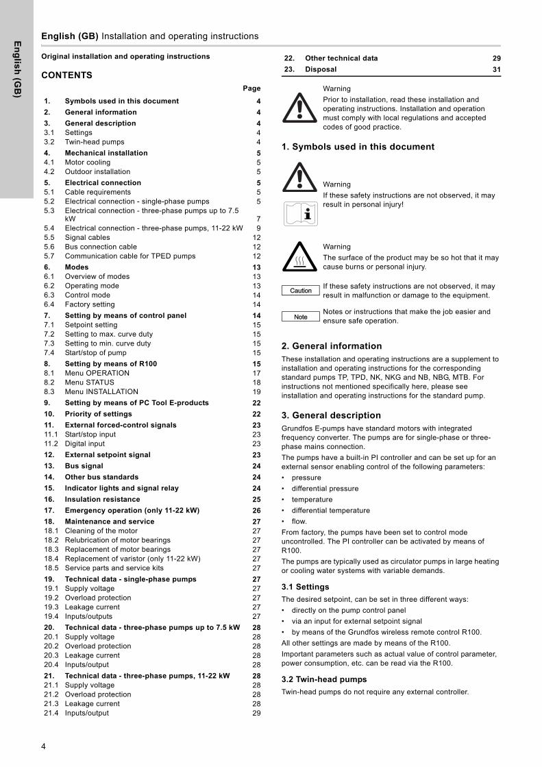
1. Symbols used in this document
2. General informationThese installation and operating instructions are a supplement to installation and operating instructions for the corresponding standard pumps TP, TPD, NK, NKG and NB, NBG, MTB. For instructions not mentioned specifically here, please see installation and operating instructions for the standard pump.
3. General descriptionGrundfos E-pumps have standard motors with integrated frequency converter. The pumps are for single-phase or three-phase mains connection.The pumps have a built-in PI controller and can be set up for an external sensor enabling control of the following parameters:• pressure• differential pressure• temperature• differential temperature• flow. From factory, the pumps have been set to control mode uncontrolled. The PI controller can be activated by means of R100.The pumps are typically used as circulator pumps in large heating or cooling water systems with variable demands.
3.1 Settings
The desired setpoint, can be set in three different ways:• directly on the pump control panel• via an input for external setpoint signal• by means of the Grundfos wireless remote control R100. All other settings are made by means of the R100. Important parameters such as actual value of control parameter, power consumption, etc. can be read via the R100.
3.2 Twin-head pumps
Twin-head pumps do not require any external controller.
1. Symbols used in this document 4
2. General information 4
3. General description 43.1 Settings 43.2 Twin-head pumps 44. Mechanical installation 54.1 Motor cooling 54.2 Outdoor installation 55. Electrical connection 55.1 Cable requirements 55.2 Electrical connection - single-phase pumps 55.3 Electrical connection - three-phase pumps up to 7.5
kW 75.4 Electrical connection - three-phase pumps, 11-22 kW 95.5 Signal cables 125.6 Bus connection cable 125.7 Communication cable for TPED pumps 126. Modes 136.1 Overview of modes 136.2 Operating mode 136.3 Control mode 146.4 Factory setting 147. Setting by means of control panel 147.1 Setpoint setting 157.2 Setting to max. curve duty 157.3 Setting to min. curve duty 157.4 Start/stop of pump 158. Setting by means of R100 158.1 Menu OPERATION 178.2 Menu STATUS 188.3 Menu INSTALLATION 199. Setting by means of PC Tool E-products 22
10. Priority of settings 22
11. External forced-control signals 2311.1 Start/stop input 2311.2 Digital input 2312. External setpoint signal 23
13. Bus signal 24
14. Other bus standards 24
15. Indicator lights and signal relay 24
16. Insulation resistance 25
17. Emergency operation (only 11-22 kW) 26
18. Maintenance and service 2718.1 Cleaning of the motor 2718.2 Relubrication of motor bearings 2718.3 Replacement of motor bearings 2718.4 Replacement of varistor (only 11-22 kW) 2718.5 Service parts and service kits 2719. Technical data - single-phase pumps 2719.1 Supply voltage 2719.2 Overload protection 2719.3 Leakage current 2719.4 Inputs/outputs 2720. Technical data - three-phase pumps up to 7.5 kW 2820.1 Supply voltage 2820.2 Overload protection 2820.3 Leakage current 2820.4 Inputs/output 2821. Technical data - three-phase pumps, 11-22 kW 2821.1 Supply voltage 2821.2 Overload protection 2821.3 Leakage current 2821.4 Inputs/output 29
22. Other technical data 29
23. Disposal 31
WarningPrior to installation, read these installation and operating instructions. Installation and operation must comply with local regulations and accepted codes of good practice.
WarningIf these safety instructions are not observed, it may result in personal injury!
WarningThe surface of the product may be so hot that it may cause burns or personal injury.
Caution If these safety instructions are not observed, it may result in malfunction or damage to the equipment.
NoteNotes or instructions that make the job easier and ensure safe operation.
4

En
gli
sh
(G
B)
4. Mechanical installation4.1 Motor cooling
To ensure sufficient cooling of motor and electronics, observe the following requirements: • Make sure that sufficient cooling air is available. • Keep the temperature of the cooling air below 40 °C. • Keep cooling fins and fan blades clean.
4.2 Outdoor installation
When installed outdoors, the pump must be provided with a suitable cover to avoid condensation on the electronic components. See fig. 1.
Fig. 1 Examples of covers
Remove the drain plug pointing downwards in order to avoid moisture and water build-up inside the motor.Vertically mounted pumps are IP55 after removal of the drain plug. Horizontally mounted pumps change enclosure class to IP54.
5. Electrical connectionFor description of how to connect E-pumps electrically, see the following pages:5.2 Electrical connection - single-phase pumps, page 55.3 Electrical connection - three-phase pumps up to 7.5 kW, page 75.4 Electrical connection - three-phase pumps, 11-22 kW, page 9.
5.1 Cable requirements
5.1.1 Cable size
Single-phase supply
1.5 mm2 / 12-14 AWG.
Three-phase supply
6-10 mm2 / 10-8 AWG.
5.1.2 Conductors
Type
Stranded copper conductors only.
Temperature rating
Temperature rating for conductor insulation: 60 °C (140 °F).Temperature rating for outer cable sheath: 75 °C (167 °F).
5.2 Electrical connection - single-phase pumps
5.2.1 Preparation
Before connecting the E-pump to the mains, take the issues illustrated in the figure below into consideration.
Fig. 2 Mains-connected pump with mains switch, backup fuse, additional protection and protective earthing
5.2.2 Protection against electric shock - indirect contact
Protective earth conductors must always have a yellow/green (PE) or yellow/green/blue (PEN) colour marking.
5.2.3 Backup fuses
For recommended fuse sizes, see section 19.1 Supply voltage.
5.2.4 Additional protection
If the pump is connected to an electric installation where an earth leakage circuit breaker (ELCB) is used as additional protection, the circuit breaker must be of a type marked with the following symbol:
The total leakage current of all the electrical equipment in the installation must be taken into account. The leakage current of the motor in normal operation can be seen in section 19.3 Leakage current. During start and at asymmetrical supply systems, the leakage current can be higher than normal and may cause the ELCB to trip.
NoteIn order to retain the UL/cURus approval, follow the additional installation procedures on page 818.
TM00
862
2 01
01 -
TM02
851
4 03
04
WarningThe user or the installer is responsible for the installation of correct earthing and protection according to local regulations. All operations must be carried out by qualified staff.
WarningNever make any connections in the pump terminal box unless all electric supply circuits have been switched off for at least 5 minutes.Note for instance that the signal relay may be connected to an external supply which is still connected when the mains supply is disconnected.
The above warning is indicated on the motor terminal box by this yellow label.
WarningThe surface of the terminal box may be above 70 °C when the pump is operating.
TM02
079
2 01
01
WarningThe pump must be earthed and protected against indirect contact in accordance with local regulations.
N
PE
L
N
L
PE
ELCB
ELCB
5
En
glis
h (G
B)
5.2.5 Motor protection
The pump requires no external motor protection. The motor incorporates thermal protection against slow overloading and blocking (IEC 34-11, TP 211).
5.2.6 Protection against mains voltage transients
The pump is protected against voltage transients by built-in varistors between phase-neutral and phase-earth.
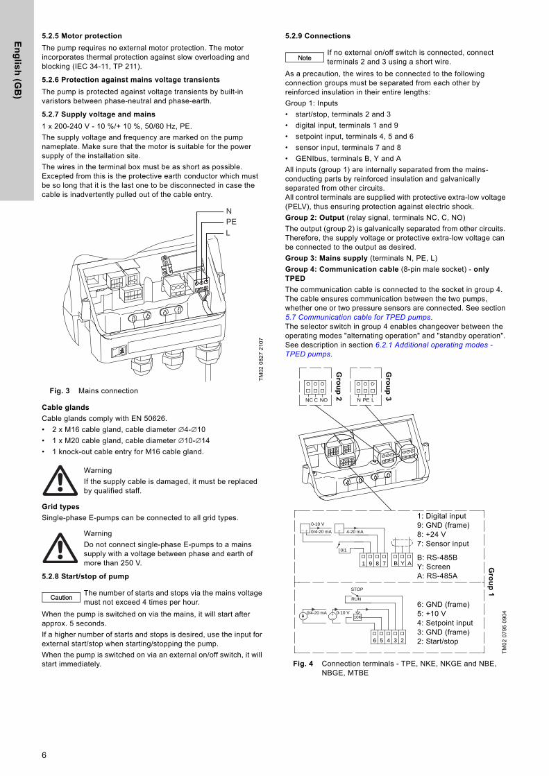
5.2.7 Supply voltage and mains
1 x 200-240 V - 10 %/+ 10 %, 50/60 Hz, PE.The supply voltage and frequency are marked on the pump nameplate. Make sure that the motor is suitable for the power supply of the installation site.The wires in the terminal box must be as short as possible. Excepted from this is the protective earth conductor which must be so long that it is the last one to be disconnected in case the cable is inadvertently pulled out of the cable entry.
Fig. 3 Mains connection
Cable glands
Cable glands comply with EN 50626.• 2 x M16 cable gland, cable diameter ∅4-∅10• 1 x M20 cable gland, cable diameter ∅10-∅14• 1 knock-out cable entry for M16 cable gland.
Grid types
Single-phase E-pumps can be connected to all grid types.
5.2.8 Start/stop of pump
When the pump is switched on via the mains, it will start after approx. 5 seconds.If a higher number of starts and stops is desired, use the input for external start/stop when starting/stopping the pump.When the pump is switched on via an external on/off switch, it will start immediately.
5.2.9 Connections
As a precaution, the wires to be connected to the following connection groups must be separated from each other by reinforced insulation in their entire lengths: Group 1: Inputs• start/stop, terminals 2 and 3• digital input, terminals 1 and 9• setpoint input, terminals 4, 5 and 6• sensor input, terminals 7 and 8• GENIbus, terminals B, Y and AAll inputs (group 1) are internally separated from the mains-conducting parts by reinforced insulation and galvanically separated from other circuits.All control terminals are supplied with protective extra-low voltage (PELV), thus ensuring protection against electric shock. Group 2: Output (relay signal, terminals NC, C, NO)The output (group 2) is galvanically separated from other circuits. Therefore, the supply voltage or protective extra-low voltage can be connected to the output as desired.Group 3: Mains supply (terminals N, PE, L)Group 4: Communication cable (8-pin male socket) - only TPED
The communication cable is connected to the socket in group 4. The cable ensures communication between the two pumps, whether one or two pressure sensors are connected. See section 5.7 Communication cable for TPED pumps.The selector switch in group 4 enables changeover between the operating modes "alternating operation" and "standby operation". See description in section 6.2.1 Additional operating modes - TPED pumps.
Fig. 4 Connection terminals - TPE, NKE, NKGE and NBE, NBGE, MTBE
TM02
082
7 21
07
WarningIf the supply cable is damaged, it must be replaced by qualified staff.
WarningDo not connect single-phase E-pumps to a mains supply with a voltage between phase and earth of more than 250 V.
Caution The number of starts and stops via the mains voltage must not exceed 4 times per hour.
PEL
N
NoteIf no external on/off switch is connected, connect terminals 2 and 3 using a short wire.
TM02
079
5 09
04
0/1
10K
RUN
STOP
NC C NO N PE L
1 9 8 7
6 5 4 3 2
B Y A
0-10 V
0/4-20 mA 4-20 mA
0/4-20 mA 0-10 V
1: Digital input 9: GND (frame)8: +24 V7: Sensor input
B: RS-485BY: ScreenA: RS-485A
6: GND (frame) 5: +10 V4: Setpoint input3: GND (frame)2: Start/stop
Gro
up
1
Gro
up
3
Gro
up
2
6
En
gli
sh
(G
B)
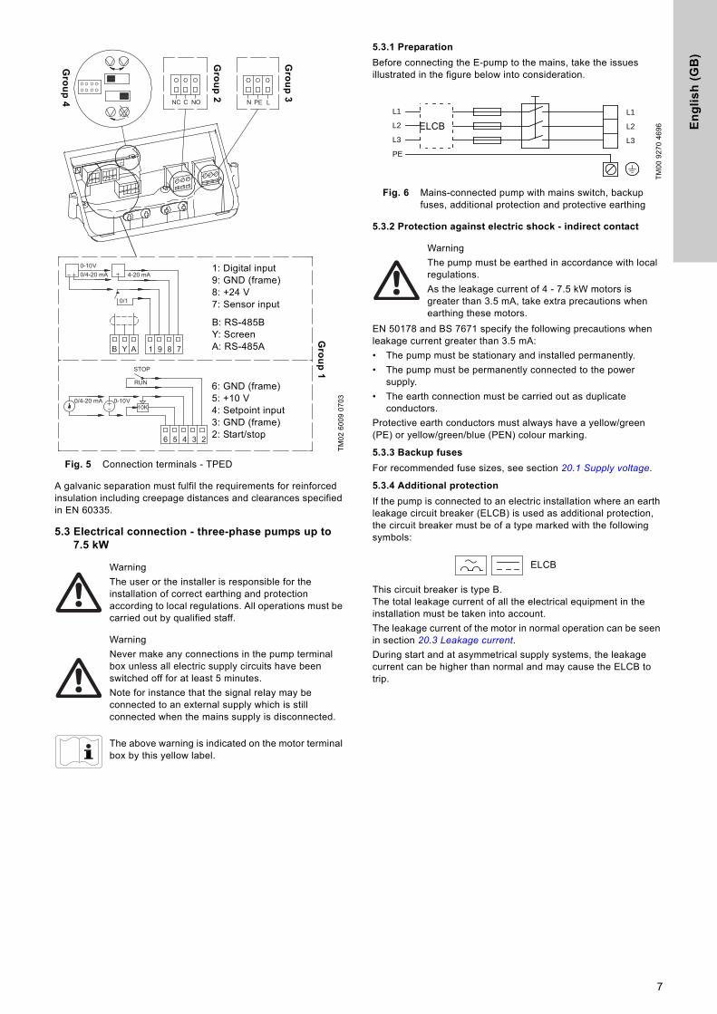
Fig. 5 Connection terminals - TPED
A galvanic separation must fulfil the requirements for reinforced insulation including creepage distances and clearances specified in EN 60335.
5.3 Electrical connection - three-phase pumps up to 7.5 kW
5.3.1 Preparation
Before connecting the E-pump to the mains, take the issues illustrated in the figure below into consideration.
Fig. 6 Mains-connected pump with mains switch, backup fuses, additional protection and protective earthing
5.3.2 Protection against electric shock - indirect contact
EN 50178 and BS 7671 specify the following precautions when leakage current greater than 3.5 mA: • The pump must be stationary and installed permanently.• The pump must be permanently connected to the power
supply.• The earth connection must be carried out as duplicate
conductors.Protective earth conductors must always have a yellow/green (PE) or yellow/green/blue (PEN) colour marking.
5.3.3 Backup fuses
For recommended fuse sizes, see section 20.1 Supply voltage.
5.3.4 Additional protection
If the pump is connected to an electric installation where an earth leakage circuit breaker (ELCB) is used as additional protection, the circuit breaker must be of a type marked with the following symbols:
This circuit breaker is type B.The total leakage current of all the electrical equipment in the installation must be taken into account. The leakage current of the motor in normal operation can be seen in section 20.3 Leakage current. During start and at asymmetrical supply systems, the leakage current can be higher than normal and may cause the ELCB to trip.
TM02
600
9 07
03
WarningThe user or the installer is responsible for the installation of correct earthing and protection according to local regulations. All operations must be carried out by qualified staff.
WarningNever make any connections in the pump terminal box unless all electric supply circuits have been switched off for at least 5 minutes.Note for instance that the signal relay may be connected to an external supply which is still connected when the mains supply is disconnected.
The above warning is indicated on the motor terminal box by this yellow label.
0/1
10K
RUN
STOP
NC C NO N PE L
1 9 8 7
6 5 4 3 2
B Y A
0-10 V0/4-20 mA 4-20 mA
0/4-20 mA 0-10 V
Gro
up
4
Gro
up
2
Gro
up
3
1: Digital input 9: GND (frame)8: +24 V7: Sensor input
B: RS-485BY: ScreenA: RS-485A
6: GND (frame) 5: +10 V4: Setpoint input3: GND (frame)2: Start/stop
Gro
up
1
TM00
927
0 46
96
WarningThe pump must be earthed in accordance with local regulations.As the leakage current of 4 - 7.5 kW motors is greater than 3.5 mA, take extra precautions when earthing these motors.
L1
L2
L3
L2
L1
L3
PE
ELCB
ELCB
7
En
glis
h (G
B)
5.3.5 Motor protection
The pump requires no external motor protection. The motor incorporates thermal protection against slow overloading and blocking (IEC 34-11, TP 211).
5.3.6 Protection against mains voltage transients
The pump is protected against voltage transients by built-in varistors between the phases and between phases and earth.
5.3.7 Supply voltage and mains
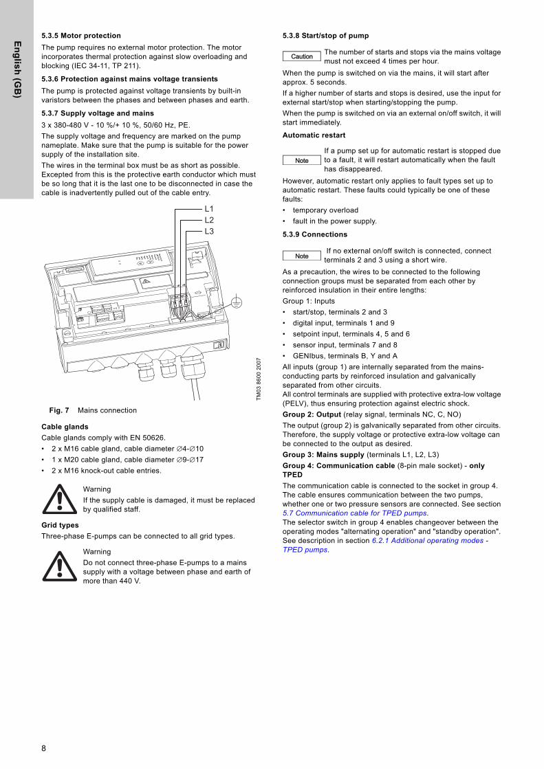
3 x 380-480 V - 10 %/+ 10 %, 50/60 Hz, PE.The supply voltage and frequency are marked on the pump nameplate. Make sure that the pump is suitable for the power supply of the installation site. The wires in the terminal box must be as short as possible. Excepted from this is the protective earth conductor which must be so long that it is the last one to be disconnected in case the cable is inadvertently pulled out of the cable entry.
Fig. 7 Mains connection
Cable glands
Cable glands comply with EN 50626.• 2 x M16 cable gland, cable diameter ∅4-∅10• 1 x M20 cable gland, cable diameter ∅9-∅17• 2 x M16 knock-out cable entries.
Grid types
Three-phase E-pumps can be connected to all grid types.
5.3.8 Start/stop of pump
When the pump is switched on via the mains, it will start after approx. 5 seconds.If a higher number of starts and stops is desired, use the input for external start/stop when starting/stopping the pump.When the pump is switched on via an external on/off switch, it will start immediately.
Automatic restart
However, automatic restart only applies to fault types set up to automatic restart. These faults could typically be one of these faults:• temporary overload• fault in the power supply.
5.3.9 Connections
As a precaution, the wires to be connected to the following connection groups must be separated from each other by reinforced insulation in their entire lengths: Group 1: Inputs• start/stop, terminals 2 and 3• digital input, terminals 1 and 9• setpoint input, terminals 4, 5 and 6• sensor input, terminals 7 and 8• GENIbus, terminals B, Y and AAll inputs (group 1) are internally separated from the mains-conducting parts by reinforced insulation and galvanically separated from other circuits.All control terminals are supplied with protective extra-low voltage (PELV), thus ensuring protection against electric shock. Group 2: Output (relay signal, terminals NC, C, NO)The output (group 2) is galvanically separated from other circuits. Therefore, the supply voltage or protective extra-low voltage can be connected to the output as desired.Group 3: Mains supply (terminals L1, L2, L3)Group 4: Communication cable (8-pin male socket) - only TPED
The communication cable is connected to the socket in group 4. The cable ensures communication between the two pumps, whether one or two pressure sensors are connected. See section 5.7 Communication cable for TPED pumps.The selector switch in group 4 enables changeover between the operating modes "alternating operation" and "standby operation". See description in section 6.2.1 Additional operating modes - TPED pumps.
TM03
860
0 20
07
WarningIf the supply cable is damaged, it must be replaced by qualified staff.
WarningDo not connect three-phase E-pumps to a mains supply with a voltage between phase and earth of more than 440 V.
L1L2L3
Caution The number of starts and stops via the mains voltage must not exceed 4 times per hour.
NoteIf a pump set up for automatic restart is stopped due to a fault, it will restart automatically when the fault has disappeared.
Note If no external on/off switch is connected, connect terminals 2 and 3 using a short wire.
8
En
gli
sh
(G
B)
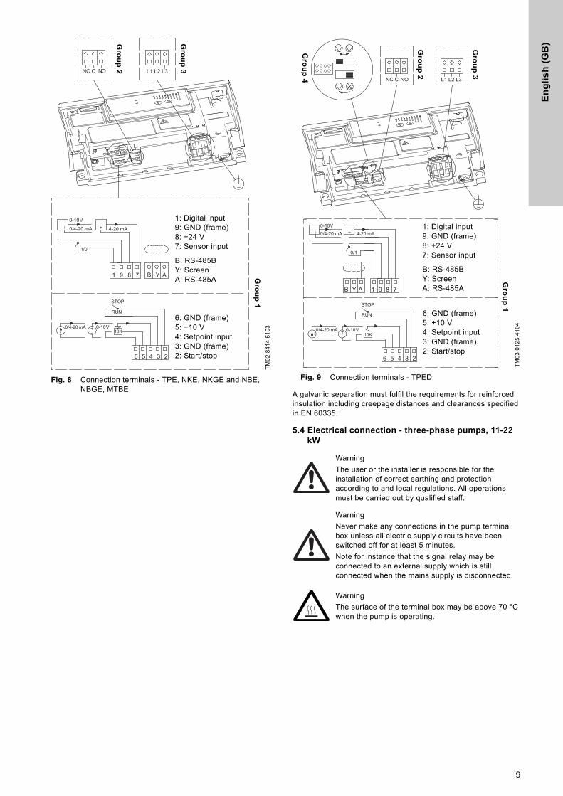
Fig. 8 Connection terminals - TPE, NKE, NKGE and NBE, NBGE, MTBE
Fig. 9 Connection terminals - TPED
A galvanic separation must fulfil the requirements for reinforced insulation including creepage distances and clearances specified in EN 60335.
5.4 Electrical connection - three-phase pumps, 11-22 kW
TM02
841
4 51
031 9 8 7 B Y A
0-10 V
0/4-20 mA 4-20 mA
1/0
NC C NO L1 L2 L3
10K
RUN
STOP
6 5 4 3 2
0/4-20 mA 0-10 V
1: Digital input 9: GND (frame)8: +24 V7: Sensor input
B: RS-485BY: ScreenA: RS-485A
6: GND (frame) 5: +10 V4: Setpoint input3: GND (frame)2: Start/stop
Gro
up
1
Gro
up
3
Gro
up
2
TM03
012
5 41
04
WarningThe user or the installer is responsible for the installation of correct earthing and protection according to and local regulations. All operations must be carried out by qualified staff.
WarningNever make any connections in the pump terminal box unless all electric supply circuits have been switched off for at least 5 minutes.Note for instance that the signal relay may be connected to an external supply which is still connected when the mains supply is disconnected.
WarningThe surface of the terminal box may be above 70 °C when the pump is operating.
0/1
10K
RUN
STOP
1 9 8 7
6 5 4 3 2
B Y A
0-10 V0/4-20 mA 4-20 mA
0/4-20 mA 0-10 V
L3L2L1NOCNC
Gro
up
4
Gro
up
2
Gro
up
3
1: Digital input 9: GND (frame)8: +24 V7: Sensor input
B: RS-485BY: ScreenA: RS-485A
6: GND (frame) 5: +10 V4: Setpoint input3: GND (frame)2: Start/stop
Gro
up
1
9
En
glis
h (G
B)
5.4.1 Preparation
Before connecting the E-pump to the mains, take the issues illustrated in the figure below into consideration.
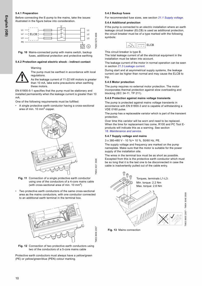
Fig. 10 Mains-connected pump with mains switch, backup fuses, additional protection and protective earthing
5.4.2 Protection against electric shock - indirect contact
EN 61800-5-1 specifies that the pump must be stationary and installed permanently when the leakage current is greater than 10 mA.One of the following requirements must be fulfilled:• A single protective earth conductor having a cross-sectional
area of min. 10 mm2 copper.
Fig. 11 Connection of a single protective earth conductor using one of the conductors of a 4-core mains cable (with cross-sectional area of min. 10 mm2)
• Two protective earth conductors of the same cross-sectional area as the mains conductors, with one conductor connected to an additional earth terminal in the terminal box.
Fig. 12 Connection of two protective earth conductors using two of the conductors of a 5-core mains cable
Protective earth conductors must always have a yellow/green (PE) or yellow/green/blue (PEN) colour marking.
5.4.3 Backup fuses
For recommended fuse sizes, see section 21.1 Supply voltage.
5.4.4 Additional protection
If the pump is connected to an electric installation where an earth leakage circuit breaker (ELCB) is used as additional protection, the circuit breaker must be of a type marked with the following symbols:
This circuit breaker is type B.The total leakage current of all the electrical equipment in the installation must be taken into account.The leakage current of the motor in normal operation can be seen in section 21.3 Leakage current. During start and at asymmetrical supply systems, the leakage current can be higher than normal and may cause the ELCB to trip.
5.4.5 Motor protection
The pump requires no external motor protection. The motor incorporates thermal protection against slow overloading and blocking (IEC 34-11, TP 211).
5.4.6 Protection against mains voltage transients
The pump is protected against mains voltage transients in accordance with EN 61800-3 and is capable of withstanding a VDE 0160 pulse.The pump has a replaceable varistor which is part of the transient protection.Over time this varistor will be worn and need to be replaced. When the time for replacement has come, R100 and PC Tool E-products will indicate this as a warning. See section 18. Maintenance and service.
5.4.7 Supply voltage and mains
3 x 380-480 V - 10 %/+ 10 %, 50/60 Hz, PE.The supply voltage and frequency are marked on the pump nameplate. Make sure that the motor is suitable for the power supply of the installation site.The wires in the terminal box must be as short as possible. Excepted from this is the protective earth conductor which must be so long that it is the last one to be disconnected in case the cable is inadvertently pulled out of the cable entry.
Fig. 13 Mains connection
TM00
927
0 46
96
WarningThe pump must be earthed in accordance with local regulations.As the leakage current of 11-22 kW motors is greater than 10 mA, take extra precautions when earthing these motors.
TM04
302
1 35
08TM
03 8
606
2007
L1
L2
L3
L2
L1
L3
PE
ELCB
TM03
860
5 20
07 -
TM04
304
8 35
08
ELCB
Torques, terminals L1-L3:Min. torque: 2.2 NmMax. torque: 2.8 Nm
10
En
gli
sh
(G
B)
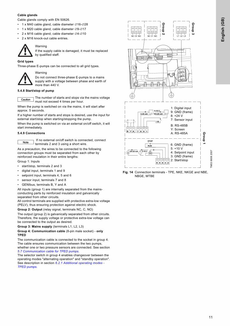
Cable glands
Cable glands comply with EN 50626.• 1 x M40 cable gland, cable diameter ∅16-∅28• 1 x M20 cable gland, cable diameter ∅9-∅17• 2 x M16 cable gland, cable diameter ∅4-∅10• 2 x M16 knock-out cable entries.
Grid types
Three-phase E-pumps can be connected to all grid types.
5.4.8 Start/stop of pump
When the pump is switched on via the mains, it will start after approx. 5 seconds.If a higher number of starts and stops is desired, use the input for external start/stop when starting/stopping the pump.When the pump is switched on via an external on/off switch, it will start immediately.
5.4.9 Connections
As a precaution, the wires to be connected to the following connection groups must be separated from each other by reinforced insulation in their entire lengths: Group 1: Inputs• start/stop, terminals 2 and 3• digital input, terminals 1 and 9• setpoint input, terminals 4, 5 and 6• sensor input, terminals 7 and 8• GENIbus, terminals B, Y and AAll inputs (group 1) are internally separated from the mains-conducting parts by reinforced insulation and galvanically separated from other circuits.All control terminals are supplied with protective extra-low voltage (PELV), thus ensuring protection against electric shock. Group 2: Output (relay signal, terminals NC, C, NO)The output (group 2) is galvanically separated from other circuits. Therefore, the supply voltage or protective extra-low voltage can be connected to the output as desired.Group 3: Mains supply (terminals L1, L2, L3)Group 4: Communication cable (8-pin male socket) - only TPED
The communication cable is connected to the socket in group 4. The cable ensures communication between the two pumps, whether one or two pressure sensors are connected. See section 5.7 Communication cable for TPED pumps.The selector switch in group 4 enables changeover between the operating modes "alternating operation" and "standby operation". See description in section 6.2.1 Additional operating modes - TPED pumps.
Fig. 14 Connection terminals - TPE, NKE, NKGE and NBE, NBGE, MTBE
WarningIf the supply cable is damaged, it must be replaced by qualified staff.
WarningDo not connect three-phase E-pumps to a mains supply with a voltage between phase and earth of more than 440 V.
Caution The number of starts and stops via the mains voltage must not exceed 4 times per hour.
Note If no external on/off switch is connected, connect terminals 2 and 3 using a short wire.
TM03
860
8 20
07
1: Digital input 9: GND (frame)8: +24 V7: Sensor input
B: RS-485BY: ScreenA: RS-485A
6: GND (frame) 5: +10 V4: Setpoint input3: GND (frame)2: Start/stop
Gro
up
1
Gro
up
2
Gro
up
3
11
En
glis
h (G
B)
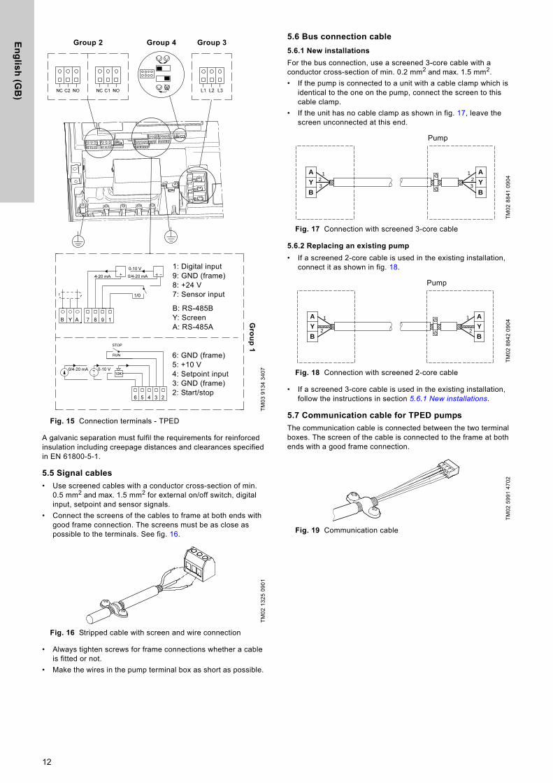
Fig. 15 Connection terminals - TPED
A galvanic separation must fulfil the requirements for reinforced insulation including creepage distances and clearances specified in EN 61800-5-1.
5.5 Signal cables
• Use screened cables with a conductor cross-section of min. 0.5 mm2 and max. 1.5 mm2 for external on/off switch, digital input, setpoint and sensor signals.
• Connect the screens of the cables to frame at both ends with good frame connection. The screens must be as close as possible to the terminals. See fig. 16.
Fig. 16 Stripped cable with screen and wire connection
• Always tighten screws for frame connections whether a cable is fitted or not.
• Make the wires in the pump terminal box as short as possible.
5.6 Bus connection cable
5.6.1 New installations
For the bus connection, use a screened 3-core cable with a conductor cross-section of min. 0.2 mm2 and max. 1.5 mm2. • If the pump is connected to a unit with a cable clamp which is
identical to the one on the pump, connect the screen to this cable clamp.
• If the unit has no cable clamp as shown in fig. 17, leave the screen unconnected at this end.
Fig. 17 Connection with screened 3-core cable
5.6.2 Replacing an existing pump
• If a screened 2-core cable is used in the existing installation, connect it as shown in fig. 18.
Fig. 18 Connection with screened 2-core cable
• If a screened 3-core cable is used in the existing installation, follow the instructions in section 5.6.1 New installations.
5.7 Communication cable for TPED pumps
The communication cable is connected between the two terminal boxes. The screen of the cable is connected to the frame at both ends with a good frame connection.
Fig. 19 Communication cable
TM03
913
4 34
07TM
02 1
325
0901
Group 4Group 2 Group 3
1: Digital input 9: GND (frame)8: +24 V7: Sensor input
B: RS-485BY: ScreenA: RS-485A
6: GND (frame) 5: +10 V4: Setpoint input3: GND (frame)2: Start/stop
Gro
up
1
TM02
884
1 09
04TM
02 8
842
0904
TM02
599
1 47
02
A
Y
B
A
Y
B
123
123
Pump
A
Y
B
A
Y
B
1
2
1
2
Pump
12
En
gli
sh
(G
B)
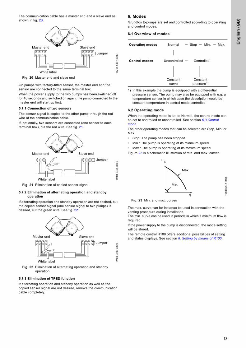
The communication cable has a master end and a slave end as shown in fig. 20.
Fig. 20 Master end and slave end
On pumps with factory-fitted sensor, the master end and the sensor are connected to the same terminal box. When the power supply to the two pumps has been switched off for 40 seconds and switched on again, the pump connected to the master end will start up first.
5.7.1 Connection of two sensors
The sensor signal is copied to the other pump through the red wire of the communication cable.If, optionally, two sensors are connected (one sensor to each terminal box), cut the red wire. See fig. 21.
Fig. 21 Elimination of copied sensor signal
5.7.2 Elimination of alternating operation and standby operation
If alternating operation and standby operation are not desired, but the copied sensor signal (one sensor signal to two pumps) is desired, cut the green wire. See fig. 22.
Fig. 22 Elimination of alternating operation and standby operation
5.7.3 Elimination of TPED function
If alternating operation and standby operation as well as the copied sensor signal are not desired, remove the communication cable completely.
6. ModesGrundfos E-pumps are set and controlled according to operating and control modes.
6.1 Overview of modes
1) In this example the pump is equipped with a differential pressure sensor. The pump may also be equipped with e.g. a temperature sensor in which case the description would be constant temperature in control mode controlled.
6.2 Operating mode
When the operating mode is set to Normal, the control mode can be set to controlled or uncontrolled. See section 6.3 Control mode. The other operating modes that can be selected are Stop, Min. or Max.• Stop: The pump has been stopped.• Min.: The pump is operating at its minimum speed.• Max.: The pump is operating at its maximum speed.Figure 23 is a schematic illustration of min. and max. curves.
Fig. 23 Min. and max. curves
The max. curve can for instance be used in connection with the venting procedure during installation.The min. curve can be used in periods in which a minimum flow is required. If the power supply to the pump is disconnected, the mode setting will be stored. The remote control R100 offers additional possibilities of setting and status displays. See section 8. Setting by means of R100.
TM04
549
7 33
09TM
04 5
495
3309
TM04
549
6 33
09
Jumper
White label
Master end Slave end
Jumper
White label
Master end Slave end
Jumper
White label
Master end Slave end
Operating modes Normal Stop Min. Max.
Control modes Uncontrolled Controlled
Constant curve
Constant pressure1)
TM00
554
7 09
95
Q
H
Max.
Min.
13
En
glis
h (G
B)
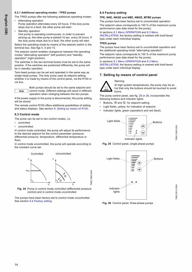
6.2.1 Additional operating modes - TPED pumps
The TPED pumps offer the following additional operating modes:• Alternating operation
Pump operation alternates every 24 hours. If the duty pump stops due to a fault, the other pump will start.
• Standby operationOne pump is operating continuously. In order to prevent seizing-up, the other pump is started 10 sec. every 24 hours. If the duty pump stops due to a fault, the other pump will start.
Select the operating mode by means of the selector switch in the terminal box. See figs 5, 9 and 15.The selector switch enables changeover between the operating modes "alternating operation" (left position) and "standby operation" (right position).The switches in the two terminal boxes must be set to the same position. If the switches are positioned differently, the pump will be in standby operation.Twin-head pumps can be set and operated in the same way as single-head pumps. The duty pump uses its setpoint setting, whether it is made by means of the control panel, via the R100 or via bus.
If the power supply to the pump is disconnected, the pump setting will be stored. The remote control R100 offers additional possibilities of setting and status displays. See section 8. Setting by means of R100.
6.3 Control mode
The pump can be set to two control modes, i.e.• controlled• uncontrolled.In control mode controlled, the pump will adjust its performance to the desired setpoint for the control parameter (pressure, differential pressure, temperature, differential temperature or flow).In control mode uncontrolled, the pump will operate according to the constant curve set.
Fig. 24 Pump in control mode controlled (differential pressure control) and in control mode uncontrolled
The pumps have been factory-set to control mode uncontrolled. See section 6.4 Factory setting.
6.4 Factory setting
TPE, NKE, NKGE and NBE, NBGE, MTBE pumps
The pumps have been factory-set to uncontrolled operation. The setpoint value corresponds to 100 % of the maximum pump performance (see data sheet for the pump). In sections 8.1 Menu OPERATION and 8.3 Menu INSTALLATION, the factory-setting is marked with bold-faced type under each individual display.
TPED pumps
The pumps have been factory-set to uncontrolled operation and the additional operating mode "alternating operation". The setpoint value corresponds to 100 % of the maximum pump performance (see data sheet for the pump). In sections 8.1 Menu OPERATION and 8.3 Menu INSTALLATION, the factory-setting is marked with bold-faced type under each individual display.
7. Setting by means of control panel
The pump control panel, see fig. 25 or 26, incorporates the following buttons and indicator lights: • Buttons, and , for setpoint setting.• Light fields, yellow, for indication of setpoint.• Indicator lights, green (operation) and red (fault).
Fig. 25 Control panel, single-phase pumps
Fig. 26 Control panel, three-phase pumps
NoteBoth pumps should be set to the same setpoint and control mode. Different settings will result in different operation when changing between the two pumps.
TM00
766
8 04
04
Q
H
setH
Q
H
Controlled Uncontrolled
WarningAt high system temperatures, the pump may be so hot that only the buttons should be touched to avoid burns.
TM00
760
0 03
04TM
02 8
513
0304
Buttons
Indicator lights
Light fields
Light fields Buttons
Indicatorlights
14
En
gli
sh
(G
B)
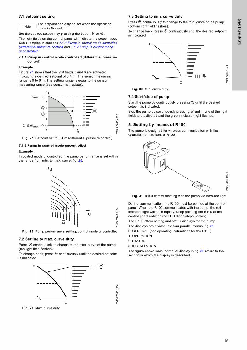
7.1 Setpoint setting
Set the desired setpoint by pressing the button or . The light fields on the control panel will indicate the setpoint set. See examples in sections 7.1.1 Pump in control mode controlled (differential pressure control) and 7.1.2 Pump in control mode uncontrolled.
7.1.1 Pump in control mode controlled (differential pressure control)
Example
Figure 27 shows that the light fields 5 and 6 are activated, indicating a desired setpoint of 3.4 m. The sensor measuring range is 0 to 6 m. The setting range is equal to the sensor measuring range (see sensor nameplate).
Fig. 27 Setpoint set to 3.4 m (differential pressure control)
7.1.2 Pump in control mode uncontrolled
Example
In control mode uncontrolled, the pump performance is set within the range from min. to max. curve, fig. 28.
Fig. 28 Pump performance setting, control mode uncontrolled
7.2 Setting to max. curve duty
Press continuously to change to the max. curve of the pump (top light field flashes).To change back, press continuously until the desired setpoint is indicated.
Fig. 29 Max. curve duty
7.3 Setting to min. curve duty
Press continuously to change to the min. curve of the pump (bottom light field flashes).To change back, press continuously until the desired setpoint is indicated.
Fig. 30 Min. curve duty
7.4 Start/stop of pump
Start the pump by continuously pressing until the desired setpoint is indicated. Stop the pump by continuously pressing until none of the light fields are activated and the green indicator light flashes.
8. Setting by means of R100 The pump is designed for wireless communication with the Grundfos remote control R100.
Fig. 31 R100 communicating with the pump via infra-red light
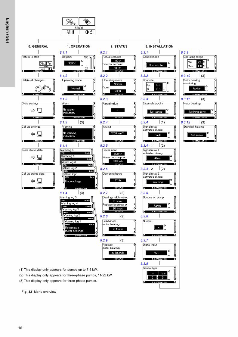
During communication, the R100 must be pointed at the control panel. When the R100 communicates with the pump, the red indicator light will flash rapidly. Keep pointing the R100 at the control panel until the red LED diode stops flashing.The R100 offers setting and status displays for the pump.The displays are divided into four parallel menus, fig. 32: 0. GENERAL (see operating instructions for the R100) 1. OPERATION 2. STATUS 3. INSTALLATION The figure above each individual display in fig. 32 refers to the section in which the display is described.
NoteThe setpoint can only be set when the operating mode is Normal.
TM03
584
5 40
06TM
00 7
746
1304
TM00
734
5 13
04
H
Q
H
Q
TM00
734
6 13
04TM
02 0
936
0501
H
Q
15
En
glis
h (G
B)
Fig. 32 Menu overview
0. GENERAL 1. OPERATION 2. STATUS 3. INSTALLATION
8.1.1 8.2.1 8.3.1 8.3.9
8.1.2 8.2.2 8.3.2 8.3.10 (3)
8.1.3 8.2.3 8.3.3 8.3.11 (3)
8.1.3 (3) 8.2.4 8.3.4 (1) 8.3.12 (3)
8.1.4 8.2.5 8.3.4 - 1 (2)
8.2.6 8.3.4 - 2 (2)
8.1.4 (3) 8.2.7 (2) 8.3.5
8.2.8 (2) 8.3.6
8.2.9 (3) 8.3.7
8.3.8
(1) This display only appears for pumps up to 7.5 kW.
(2) This display only appears for three-phase pumps, 11-22 kW.
(3) This display only appears for three-phase pumps.
16
En
gli
sh
(G
B)
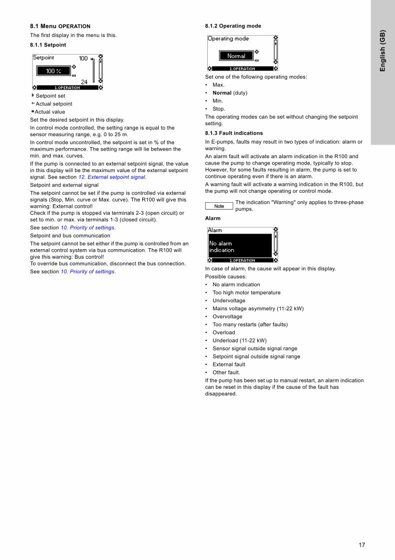
8.1 Menu OPERATION
The first display in the menu is this.
8.1.1 Setpoint
Setpoint set Actual setpoint Actual value
Set the desired setpoint in this display.In control mode controlled, the setting range is equal to the sensor measuring range, e.g. 0 to 25 m.In control mode uncontrolled, the setpoint is set in % of the maximum performance. The setting range will lie between the min. and max. curves.If the pump is connected to an external setpoint signal, the value in this display will be the maximum value of the external setpoint signal. See section 12. External setpoint signal.Setpoint and external signalThe setpoint cannot be set if the pump is controlled via external signals (Stop, Min. curve or Max. curve). The R100 will give this warning: External control! Check if the pump is stopped via terminals 2-3 (open circuit) or set to min. or max. via terminals 1-3 (closed circuit). See section 10. Priority of settings.Setpoint and bus communicationThe setpoint cannot be set either if the pump is controlled from an external control system via bus communication. The R100 will give this warning: Bus control! To override bus communication, disconnect the bus connection.See section 10. Priority of settings.
8.1.2 Operating mode
Set one of the following operating modes: • Max. • Normal (duty) • Min. • Stop. The operating modes can be set without changing the setpoint setting.
8.1.3 Fault indications
In E-pumps, faults may result in two types of indication: alarm or warning. An alarm fault will activate an alarm indication in the R100 and cause the pump to change operating mode, typically to stop. However, for some faults resulting in alarm, the pump is set to continue operating even if there is an alarm.A warning fault will activate a warning indication in the R100, but the pump will not change operating or control mode.
Alarm
In case of alarm, the cause will appear in this display. Possible causes: • No alarm indication • Too high motor temperature • Undervoltage • Mains voltage asymmetry (11-22 kW)• Overvoltage • Too many restarts (after faults) • Overload • Underload (11-22 kW) • Sensor signal outside signal range • Setpoint signal outside signal range • External fault • Other fault. If the pump has been set up to manual restart, an alarm indication can be reset in this display if the cause of the fault has disappeared.
NoteThe indication "Warning" only applies to three-phase pumps.
17
En
glis
h (G
B)
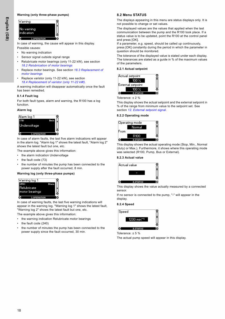
Warning (only three-phase pumps)
In case of warning, the cause will appear in this display. Possible causes: • No warning indication • Sensor signal outside signal range • Relubricate motor bearings (only 11-22 kW), see section
18.2 Relubrication of motor bearings • Replace motor bearings. See section 18.3 Replacement of
motor bearings
• Replace varistor (only 11-22 kW), see section 18.4 Replacement of varistor (only 11-22 kW).
A warning indication will disappear automatically once the fault has been remedied.
8.1.4 Fault log
For both fault types, alarm and warning, the R100 has a log function.
Alarm log
In case of alarm faults, the last five alarm indications will appear in the alarm log. "Alarm log 1" shows the latest fault, "Alarm log 2" shows the latest fault but one, etc. The example above gives this information: • the alarm indication Undervoltage • the fault code (73) • the number of minutes the pump has been connected to the
power supply after the fault occurred, 8 min.
Warning log (only three-phase pumps)
In case of warning faults, the last five warning indications will appear in the warning log. "Warning log 1" shows the latest fault, "Warning log 2" shows the latest fault but one, etc.The example above gives this information: • the warning indication Relubricate motor bearings • the fault code (240) • the number of minutes the pump has been connected to the
power supply since the fault occurred, 30 min.
8.2 Menu STATUS
The displays appearing in this menu are status displays only. It is not possible to change or set values. The displayed values are the values that applied when the last communication between the pump and the R100 took place. If a status value is to be updated, point the R100 at the control panel and press [OK]. If a parameter, e.g. speed, should be called up continuously, press [OK] constantly during the period in which the parameter in question should be monitored.The tolerance of the displayed value is stated under each display. The tolerances are stated as a guide in % of the maximum values of the parameters.
8.2.1 Actual setpoint
Tolerance: ± 2 %This display shows the actual setpoint and the external setpoint in % of the range from minimum value to the setpoint set. See section 12. External setpoint signal.
8.2.2 Operating mode
This display shows the actual operating mode (Stop, Min., Normal (duty) or Max.). Furthermore, it shows where this operating mode was selected (R100, Pump, Bus or External).
8.2.3 Actual value
This display shows the value actually measured by a connected sensor.If no sensor is connected to the pump, "-" will appear in the display.
8.2.4 Speed
Tolerance: ± 5 %The actual pump speed will appear in this display.
18
En
gli
sh
(G
B)
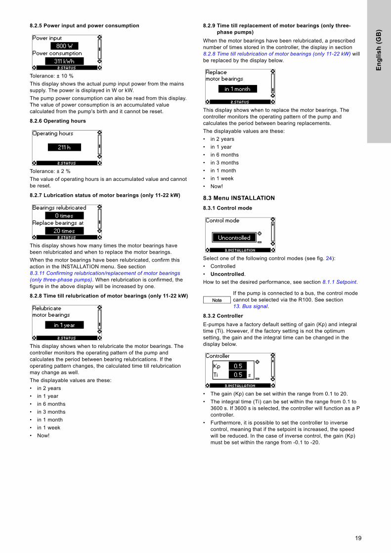
8.2.5 Power input and power consumption
Tolerance: ± 10 % This display shows the actual pump input power from the mains supply. The power is displayed in W or kW.The pump power consumption can also be read from this display. The value of power consumption is an accumulated value calculated from the pump's birth and it cannot be reset.
8.2.6 Operating hours
Tolerance: ± 2 % The value of operating hours is an accumulated value and cannot be reset.
8.2.7 Lubrication status of motor bearings (only 11-22 kW)
This display shows how many times the motor bearings have been relubricated and when to replace the motor bearings.When the motor bearings have been relubricated, confirm this action in the INSTALLATION menu. See section 8.3.11 Confirming relubrication/replacement of motor bearings (only three-phase pumps). When relubrication is confirmed, the figure in the above display will be increased by one.
8.2.8 Time till relubrication of motor bearings (only 11-22 kW)
This display shows when to relubricate the motor bearings. The controller monitors the operating pattern of the pump and calculates the period between bearing relubrications. If the operating pattern changes, the calculated time till relubrication may change as well.The displayable values are these:• in 2 years • in 1 year • in 6 months • in 3 months • in 1 month • in 1 week • Now!
8.2.9 Time till replacement of motor bearings (only three-phase pumps)
When the motor bearings have been relubricated, a prescribed number of times stored in the controller, the display in section 8.2.8 Time till relubrication of motor bearings (only 11-22 kW) will be replaced by the display below.
This display shows when to replace the motor bearings. The controller monitors the operating pattern of the pump and calculates the period between bearing replacements. The displayable values are these:• in 2 years • in 1 year • in 6 months • in 3 months • in 1 month • in 1 week • Now!
8.3 Menu INSTALLATION
8.3.1 Control mode
Select one of the following control modes (see fig. 24): • Controlled • Uncontrolled. How to set the desired performance, see section 8.1.1 Setpoint.
8.3.2 Controller
E-pumps have a factory default setting of gain (Kp) and integral time (Ti). However, if the factory setting is not the optimum setting, the gain and the integral time can be changed in the display below.
• The gain (Kp) can be set within the range from 0.1 to 20.• The integral time (Ti) can be set within the range from 0.1 to
3600 s. If 3600 s is selected, the controller will function as a P controller.
• Furthermore, it is possible to set the controller to inverse control, meaning that if the setpoint is increased, the speed will be reduced. In the case of inverse control, the gain (Kp) must be set within the range from -0.1 to -20.
NoteIf the pump is connected to a bus, the control mode cannot be selected via the R100. See section 13. Bus signal.
19
En
glis
h (G
B)
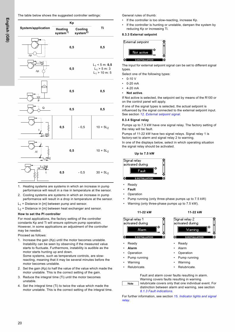
The table below shows the suggested controller settings:
1. Heating systems are systems in which an increase in pump performance will result in a rise in temperature at the sensor.
2. Cooling systems are systems in which an increase in pump performance will result in a drop in temperature at the sensor.
L1 = Distance in [m] between pump and sensor.L2 = Distance in [m] between heat exchanger and sensor.
How to set the PI controller
For most applications, the factory setting of the controller constants Kp and Ti will ensure optimum pump operation. However, in some applications an adjustment of the controller may be needed.Proceed as follows:1. Increase the gain (Kp) until the motor becomes unstable.
Instability can be seen by observing if the measured value starts to fluctuate. Furthermore, instability is audible as the motor starts hunting up and down.Some systems, such as temperature controls, are slow-reacting, meaning that it may be several minutes before the motor becomes unstable.
2. Set the gain (Kp) to half the value of the value which made the motor unstable. This is the correct setting of the gain.
3. Reduce the integral time (Ti) until the motor becomes unstable.
4. Set the integral time (Ti) to twice the value which made the motor unstable. This is the correct setting of the integral time.
General rules of thumb:• If the controller is too slow-reacting, increase Kp.• If the controller is hunting or unstable, dampen the system by
reducing Kp or increasing Ti.
8.3.3 External setpoint
The input for external setpoint signal can be set to different signal types.Select one of the following types:• 0-10 V • 0-20 mA • 4-20 mA • Not active. If Not active is selected, the setpoint set by means of the R100 or on the control panel will apply. If one of the signal types is selected, the actual setpoint is influenced by the signal connected to the external setpoint input. See section 12. External setpoint signal.
8.3.4 Signal relay
Pumps up to 7.5 kW have one signal relay. The factory setting of the relay will be fault.Pumps of 11-22 kW have two signal relays. Signal relay 1 is factory-set to alarm and signal relay 2 to warning.In one of the displays below, select in which operating situation the signal relay should be activated.
For further information, see section 15. Indicator lights and signal relay.
System/application
Kp
TiHeating system1)
Cooling system2)
0,5 0,5
0,5L1 < 5 m: 0,5L1 > 5 m: 3
L1 > 10 m: 5
0,5 0,5
0,5 0,5
0,5 - 0,5 10 + 5L2
0,5 10 + 5L2
0,5 - 0,5 30 + 5L2
p
L1 [m]
p
p
Q
t
L2 [m]
t
L2 [m]
L2 [m]
t
Up to 7.5 kW
• Ready • Fault • Operation • Pump running (only three-phase pumps up to 7.5 kW)• Warning (only three-phase pumps up to 7.5 kW).
11-22 kW 11-22 kW
• Ready • Alarm • Operation • Pump running • Warning • Relubricate.
• Ready • Alarm • Operation • Pump running • Warning• Relubricate.
Note
Fault and alarm cover faults resulting in alarm.Warning covers faults resulting in warning.relubricate covers only that one individual event. For distinction between alarm and warning, see section 8.1.3 Fault indications.
20
En
gli
sh
(G
B)
8.3.5 Buttons on pump
The operating buttons and on the control panel can be set to these values:• Active • Not active. When set to Not active (locked), the buttons do not function. Set the buttons to Not active if the pump should be controlled via an external control system.
8.3.6 Pump number
A number between 1 and 64 can be allocated to the pump. In the case of bus communication, a number must be allocated to each pump.
8.3.7 Digital input
The digital input of the pump (terminal 1, fig. 4, 8 or 14) can be set to different functions. Select one of the following functions: • Min. (min. curve) • Max. (max. curve). The selected function is activated by closing the contact between terminals 1 and 9. See figs 4, 8 and 14.See also section 11.2 Digital input.Min.: When the input is activated, the pump will operate according to the min. curve. Max.: When the input is activated, the pump will operate according to the max. curve.
8.3.8 Sensor
The setting of the sensor is only relevant in the case of controlled operation. Select among the following values:• Sensor output signal
0-10 V0-20 mA4-20 mA
• Unit of measurement of sensor:bar, mbar, m, kPa, psi, ft, m3/h, m3/s, l/s, gpm, °C, °F, %
• Sensor measuring range.
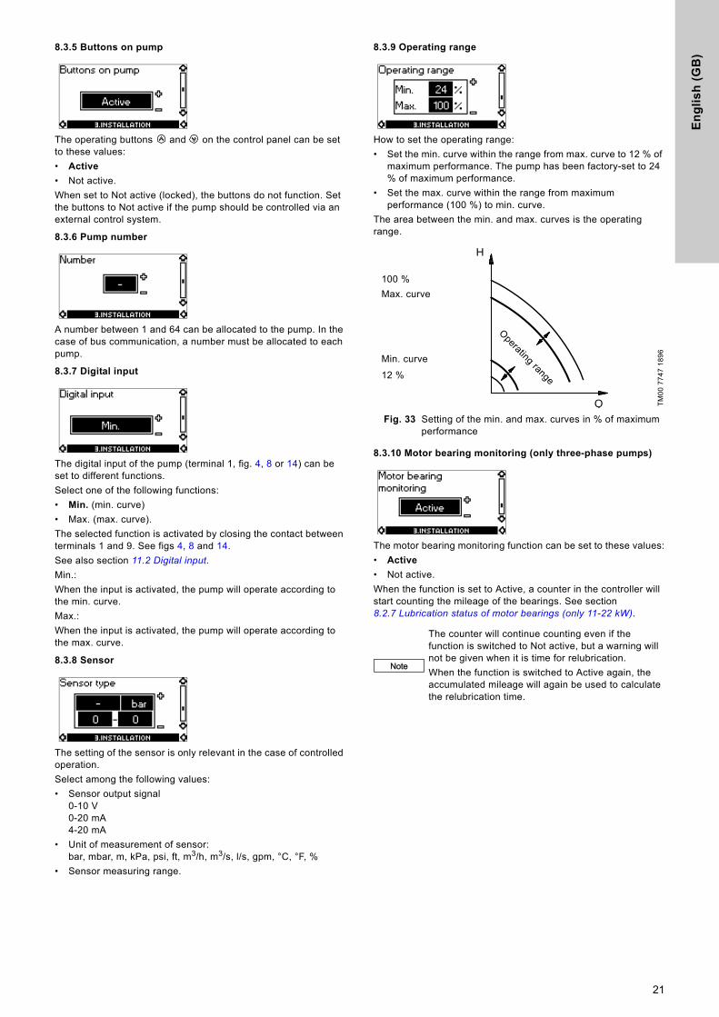
8.3.9 Operating range
How to set the operating range:• Set the min. curve within the range from max. curve to 12 % of
maximum performance. The pump has been factory-set to 24 % of maximum performance.
• Set the max. curve within the range from maximum performance (100 %) to min. curve.
The area between the min. and max. curves is the operating range.
Fig. 33 Setting of the min. and max. curves in % of maximum performance
8.3.10 Motor bearing monitoring (only three-phase pumps)
The motor bearing monitoring function can be set to these values:• Active • Not active. When the function is set to Active, a counter in the controller will start counting the mileage of the bearings. See section 8.2.7 Lubrication status of motor bearings (only 11-22 kW).
TM00
774
7 18
96Note
The counter will continue counting even if the function is switched to Not active, but a warning will not be given when it is time for relubrication. When the function is switched to Active again, the accumulated mileage will again be used to calculate the relubrication time.
Q
H
100 %Max. curve
12 %Min. curve
Operating range
21

En
glis
h (G
B)
8.3.11 Confirming relubrication/replacement of motor bearings (only three-phase pumps)
This function can be set to these values:• Relubricated (only 11-22 kW) • Replaced • Nothing done. When the bearing monitoring function is Active, the controller will give a warning indication when the motor bearings are due to be relubricated or replaced. See section 8.1.3 Fault indications.When the motor bearings have been relubricated or replaced, confirm this action in the above display by pressing [OK].
8.3.12 Standstill heating (only three-phase pumps)
The standstill heating function can be set to these values:• Active • Not active.When the function is set to Active, a low voltage will be applied to the motor windings when the pump is not operating. The applied voltage will ensure that sufficient heat is generated to avoid condensation in the motor.
9. Setting by means of PC Tool E-productsSpecial setup requirements differing from the settings available via the R100 require the use of Grundfos PC Tool E-products. This again requires the assistance of a Grundfos service technician or engineer. Contact your local Grundfos company for more information.
10. Priority of settingsThe priority of settings depends on two factors:1. control source2. settings.
2. Settings
• Operating mode Stop• Operating mode Max. (max. curve)• Operating mode Min. (min. curve)• Setpoint setting.An E-pump can be controlled by different control sources at the same time, and each of these sources can be set differently. Consequently, it is necessary to set an order of priority of the control sources and the settings.
Priority of settings without bus communication
Example: If the E-pump has been set to operating mode Max. (max. frequency) via an external signal, such as digital input, the control panel or R100 can only set the E-pump to operating mode Stop.
NoteRelubricated cannot be selected for a period of time after confirming relubrication.
1. Control source
Control panel
R100
External signals (external setpoint signal, digital inputs, etc.)
Communication from another control system via bus
NoteIf two or more settings are activated at the same time, the pump will operate according to the function with the highest priority.
Priority Control panel or R100 External signals
1 Stop
2 Max.
3 Stop
4 Max.
5 Min. Min.
6 Setpoint setting Setpoint setting
22
En
gli
sh
(G
B)
Priority of settings with bus communication
Example: If the E-pump is operating according to a setpoint set via bus communication, the control panel or R100 can set the E-pump to operating mode Stop or Max., and the external signal can only set the E-pump to operating mode Stop.
11. External forced-control signals The pump has inputs for external signals for these forced-control functions: • Start/stop of pump• Digital function.
11.1 Start/stop input
Functional diagram: Start/stop input
11.2 Digital input
By means of the R100, one of the following functions can be selected for the digital input: • Normal duty • Min. curve • Max. curve.
Functional diagram: Input for digital function
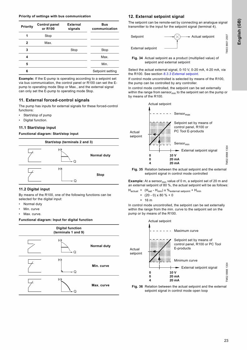
12. External setpoint signalThe setpoint can be remote-set by connecting an analogue signal transmitter to the input for the setpoint signal (terminal 4).
Fig. 34 Actual setpoint as a product (multiplied value) of setpoint and external setpoint
Select the actual external signal, 0-10 V, 0-20 mA, 4-20 mA, via the R100. See section 8.3.3 External setpoint.If control mode uncontrolled is selected by means of the R100, the pump can be controlled by any controller.In control mode controlled, the setpoint can be set externally within the range from sensormin to the setpoint set on the pump or by means of the R100.
Fig. 35 Relation between the actual setpoint and the external setpoint signal in control mode controlled
Example: At a sensormin value of 0 m, a setpoint set of 20 m and an external setpoint of 80 %, the actual setpoint will be as follows:Hactual = (Hset - Hmin) x %external setpoint + Hmin
= (20 - 0) x 80 % + 0 = 16 m
In control mode uncontrolled, the setpoint can be set externally within the range from the min. curve to the setpoint set on the pump or by means of the R100.
Fig. 36 Relation between the actual setpoint and the external setpoint signal in control mode open loop
PriorityControl panel
or R100External signals
Bus communication
1 Stop
2 Max.
3 Stop Stop
4 Max.
5 Min.
6 Setpoint setting
Start/stop (terminals 2 and 3)
Normal duty
Stop
Digital function (terminals 1 and 9)
Normal duty
Min. curve
Max. curve
Q
H
Q
H
Q
H
Q
H
Q
H
TM03
860
1 20
07TM
02 8
988
1304
TM02
898
8 13
04
Setpoint
External setpoint
Actual setpoint
0 10 V0 20 mA4 20 mA
Actual setpoint
Sensormax
Setpoint set by means of control panel, R100 or PC Tool E-products
Sensormin
External setpoint signal
Actual setpoint
0 10 V0 20 mA4 20 mA
Actual setpoint
Maximum curve
Setpoint set by means of control panel, R100 or PC Tool E-products
Minimum curve
External setpoint signal
Actual setpoint
23

En
glis
h (G
B)
13. Bus signal The pump supports serial communication via an RS-485 input. The communication is carried out according to the Grundfos bus protocol, GENIbus protocol, and enables connection to a building management system or another external control system.Operating parameters, such as setpoint, operating mode, etc. can be remote-set via the bus signal. At the same time, the pump can provide status information about important parameters, such as actual value of control parameter, input power, fault indications, etc. Contact Grundfos for further details.
14. Other bus standards Grundfos offers various bus solutions with communication according to other standards.
15. Indicator lights and signal relay The operating condition of the pump is indicated by the green and red indicator lights fitted on the pump control panel and inside the terminal box. See figs 37 and 38.
Fig. 37 Position of indicator lights on single-phase pumps
Fig. 38 Position of indicator lights on three-phase pumps
Besides, the pump incorporates an output for a potential-free signal via an internal relay.For signal relay output values, see section 8.3.4 Signal relay.
NoteIf a bus signal is used, the number of settings available via the R100 will be reduced.
TM00
760
0 03
04
TM02
083
8 02
03
Green Red
GreenRed
TM02
851
3 03
04
TM02
903
6 44
04
TM03
906
3 33
07Green Red
GreenRed
Green
Red
24
En
gli
sh
(G
B)
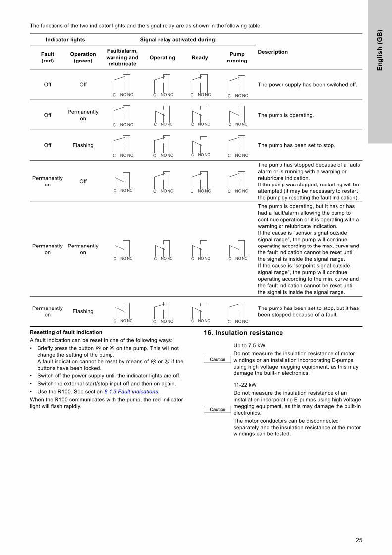
The functions of the two indicator lights and the signal relay are as shown in the following table:
Resetting of fault indication
A fault indication can be reset in one of the following ways: • Briefly press the button or on the pump. This will not
change the setting of the pump. A fault indication cannot be reset by means of or if the buttons have been locked.
• Switch off the power supply until the indicator lights are off. • Switch the external start/stop input off and then on again.• Use the R100. See section 8.1.3 Fault indications.When the R100 communicates with the pump, the red indicator light will flash rapidly.
16. Insulation resistance
Indicator lights Signal relay activated during:
DescriptionFault(red)
Operation (green)
Fault/alarm, warning and relubricate
Operating ReadyPump
running
Off Off The power supply has been switched off.
Off Permanently on The pump is operating.
Off Flashing The pump has been set to stop.
Permanently on Off
The pump has stopped because of a fault/alarm or is running with a warning or relubricate indication.If the pump was stopped, restarting will be attempted (it may be necessary to restart the pump by resetting the fault indication).
Permanently on
Permanently on
The pump is operating, but it has or has had a fault/alarm allowing the pump to continue operation or it is operating with a warning or relubricate indication.If the cause is "sensor signal outside signal range", the pump will continue operating according to the max. curve and the fault indication cannot be reset until the signal is inside the signal range.If the cause is "setpoint signal outside signal range", the pump will continue operating according to the min. curve and the fault indication cannot be reset until the signal is inside the signal range.
Permanently on Flashing The pump has been set to stop, but it has
been stopped because of a fault.
NCNOC NCNOC NCNOC NCNOC
NCNOC C NO NC C NO NC C NO NC
NCNOC NCNOC C NO NC NCNOC
C NO NC NCNOC NCNOC NCNOC
C NO NC C NO NC C NO NC C NO NC
C NO NC NCNOC C NO NC NCNOC
Caution
Up to 7.5 kWDo not measure the insulation resistance of motor windings or an installation incorporating E-pumps using high voltage megging equipment, as this may damage the built-in electronics.
Caution
11-22 kWDo not measure the insulation resistance of an installation incorporating E-pumps using high voltage megging equipment, as this may damage the built-in electronics. The motor conductors can be disconnected separately and the insulation resistance of the motor windings can be tested.
25
En
glis
h (G
B)
17. Emergency operation (only 11-22 kW)
If the pump has stopped and it does not restart after you have gone through normal remedies, the reason could be a faulty frequency converter. If this is the case, it is possible to establish emergency operation of the pump. But before you change to emergency operation, we recommend you to check these points:• Check that the mains supply is OK.• Check that control signals are working (start/stop signals).• Check that all alarms have been reset.• Make a resistance test on the motor windings (disconnect the
motor conductors from the terminal box).If the pump still does not start, the frequency converter is faulty.To establish emergency operation, proceed as follows:1. Disconnect the three mains conductors, L1, L2, L3, from the
terminal box, but leave the protective earth conductor(s) in position on the PE terminal(s).
Fig. 39 Disconnecting the mains conductors
2. Disconnect the motor supply conductors, U/W1, V/U1, W/V1, from the terminal box.
Fig. 40 Disconnecting the motor supply conductors
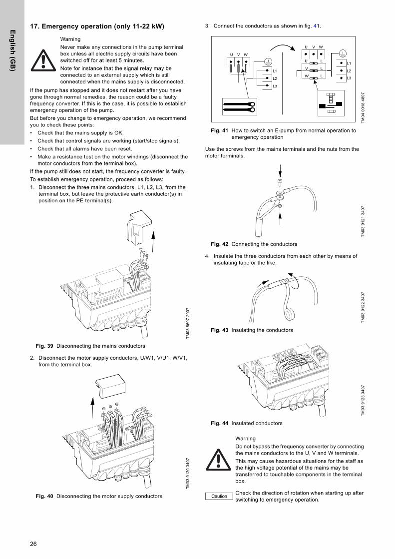
3. Connect the conductors as shown in fig. 41.
Fig. 41 How to switch an E-pump from normal operation to emergency operation
Use the screws from the mains terminals and the nuts from the motor terminals.
Fig. 42 Connecting the conductors
4. Insulate the three conductors from each other by means of insulating tape or the like.
Fig. 43 Insulating the conductors
Fig. 44 Insulated conductors
WarningNever make any connections in the pump terminal box unless all electric supply circuits have been switched off for at least 5 minutes.Note for instance that the signal relay may be connected to an external supply which is still connected when the mains supply is disconnected.
TM03
860
7 20
07TM
03 9
120
3407
TM04
001
8 48
07TM
03 9
121
3407
TM03
912
2 34
07TM
03 9
123
3407
WarningDo not bypass the frequency converter by connecting the mains conductors to the U, V and W terminals.This may cause hazardous situations for the staff as the high voltage potential of the mains may be transferred to touchable components in the terminal box.
Caution Check the direction of rotation when starting up after switching to emergency operation.
26
En
gli
sh
(G
B)
18. Maintenance and service18.1 Cleaning of the motor
Keep the motor cooling fins and fan blades clean to ensure sufficient cooling of the motor and electronics.
18.2 Relubrication of motor bearings
Pumps up to 7.5 kW
The motor bearings are of the closed type and greased for life. The bearings cannot be relubricated.
Pumps of 11-22 kW
The motor bearings are of the open type and must be relubricated regularly.The motor bearings are pre-lubricated on delivery. The built-in bearing monitoring function will give a warning indication on the R100 when the motor bearings are due to be relubricated.
When relubricating the first time, use the double quantity of grease as the lubricating channel is still empty.The recommended grease type is a polycarbamide-based lubricating grease.
18.3 Replacement of motor bearings
Three-phase motors have built-in bearing monitoring function which will give a warning indication on the R100 when the motor bearings are due to be replaced.
18.4 Replacement of varistor (only 11-22 kW)
The varistor protects the pump against mains voltage transients. If voltage transients occur, the varistor will be worn over time and need to be replaced. The more transients, the more quickly the varistor will be worn. When it is time to replace the varistor, R100 and PC Tool E-products will indicate this as a warning.A Grundfos technician is required for replacement of the varistor. Contact your local Grundfos company for assistance.
18.5 Service parts and service kits
For further information on service parts and service kits, visit www.Grundfos.com, select country, select WebCAPS.
19. Technical data - single-phase pumps
19.1 Supply voltage
1 x 200-240 V - 10 %/+ 10 %, 50/60 Hz - 2 %/+ 2 %, PE.
Recommended fuse size
Motor sizes up to 1.1 kW: Max. 10 A.Standard as well as quick-blow or slow-blow fuses may be used.
19.2 Overload protection
The overload protection of the E-motor has the same characteristic as an ordinary motor protector. As an example, the E-motor can stand an overload of 110 % of Inom for 1 min.
19.3 Leakage current
Earth leakage current < 3.5 mA.The leakage currents are measured in accordance with EN 61800-5-1.
19.4 Inputs/outputs
Start/stop
External potential-free contact. Voltage: 5 VDC. Current: < 5 mA.Screened cable: 0.5 - 1.5 mm2 / 28-16 AWG.
Digital
External potential-free contact. Voltage: 5 VDC. Current: < 5 mA.Screened cable: 0.5 - 1.5 mm2 / 28-16 AWG.
Setpoint signals
• Potentiometer0-10 VDC, 10 kΩ (via internal voltage supply).Screened cable: 0.5 - 1.5 mm2 / 28-16 AWG.Maximum cable length: 100 m.
• Voltage signal0-10 VDC, Ri > 50 kΩ.Tolerance: + 0 %/- 3 % at maximum voltage signal. Screened cable: 0.5 - 1.5 mm2 / 28-16 AWG.Maximum cable length: 500 m.
• Current signalDC 0-20 mA/4-20 mA, Ri = 175 Ω.Tolerance: + 0 %/- 3 % at maximum current signal. Screened cable: 0.5 - 1.5 mm2 / 28-16 AWG.Maximum cable length: 500 m.
Sensor signals
• Voltage signal0-10 VDC, Ri > 50 kΩ (via internal voltage supply).Tolerance: + 0 %/- 3 % at maximum voltage signal. Screened cable: 0.5 - 1.5 mm2 / 28-16 AWG.Maximum cable length: 500 m.
• Current signalDC 0-20 mA/4-20 mA, Ri = 175 Ω.Tolerance: + 0 %/- 3 % at maximum current signal. Screened cable: 0.5 - 1.5 mm2 / 28-16 AWG.Maximum cable length: 500 m.
Internal power supplies
• 10 V power supply for external potentiometer:Max. load: 2.5 mA.Short-circuit-protected.
• 24 V power supply for sensors:Max. load: 40 mA.Short-circuit-protected.
Signal relay output
Potential-free changeover contact.Maximum contact load: 250 VAC, 2 A, cos φ 0.3 - 1. Minimum contact load: 5 VDC, 10 mA.Screened cable: 0.5 - 2.5 mm2 / 28-12 AWG.Maximum cable length: 500 m.
Bus input
Grundfos bus protocol, GENIbus protocol, RS-485. Screened 3-core cable: 0.2 - 1.5 mm2 / 28-16 AWG.Maximum cable length: 500 m.
NoteBefore relubrication, remove the bottom plug in the motor flange and the plug in the bearing cover to ensure that old and excess grease can escape.
Frame size
Quantity of grease[ml]
Drive end Non-drive end
MGE 160 13 13MGE 180 15 15
27

En
glis
h (G
B)
20. Technical data - three-phase pumps up to 7.5 kW
20.1 Supply voltage
3 x 380-480 V - 10 %/+ 10 %, 50/60 Hz - 2 %/+ 2 %, PE.
Recommended fuse sizes
Motor sizes from 0.55 to 5.5 kW: Max. 16 A. Motor size 7.5 kW: Max. 32 A.Standard as well as quick-blow or slow-blow fuses may be used.
20.2 Overload protection
The overload protection of the E-motor has the same characteristic as an ordinary motor protector. As an example, the E-motor can stand an overload of 110 % of Inom for 1 min.
20.3 Leakage current
The leakage currents are measured in accordance with EN 61800-5-1.
20.4 Inputs/output
Start/stop
External potential-free contact. Voltage: 5 VDC. Current: < 5 mA.Screened cable: 0.5 - 1.5 mm2 / 28-16 AWG.
Digital
External potential-free contact. Voltage: 5 VDC. Current: < 5 mA.Screened cable: 0.5 - 1.5 mm2 / 28-16 AWG.
Setpoint signals
• Potentiometer0-10 VDC, 10 kΩ (via internal voltage supply).Screened cable: 0.5 - 1.5 mm2 / 28-16 AWG.Maximum cable length: 100 m.
• Voltage signal0-10 VDC, Ri > 50 kΩ. Tolerance: + 0 %/- 3 % at maximum voltage signal. Screened cable: 0.5 - 1.5 mm2 / 28-16 AWG.Maximum cable length: 500 m.
• Current signalDC 0-20 mA/4-20 mA, Ri = 175 Ω.Tolerance: + 0 %/- 3 % at maximum current signal. Screened cable: 0.5 - 1.5 mm2 / 28-16 AWG.Maximum cable length: 500 m.
Sensor signals
• Voltage signal0-10 VDC, Ri > 50 kΩ (via internal voltage supply).Tolerance: + 0 %/- 3 % at maximum voltage signal. Screened cable: 0.5 - 1.5 mm2 / 28-16 AWG.Maximum cable length: 500 m.
• Current signalDC 0-20 mA/4-20 mA, Ri = 175 Ω.Tolerance: + 0 %/- 3 % at maximum current signal. Screened cable: 0.5 - 1.5 mm2 / 28-16 AWG.Maximum cable length: 500 m.
Internal power supplies
• 10 V power supply for external potentiometer:Max. load: 2.5 mA.Short-circuit-protected.
• 24 V power supply for sensors:Max. load: 40 mA.Short-circuit-protected.
Signal relay output
Potential-free changeover contact.Maximum contact load: 250 VAC, 2 A, cos φ 0.3 - 1. Minimum contact load: 5 VDC, 10 mA.Screened cable: 0.5 - 2.5 mm2 / 28-12 AWG.Maximum cable length: 500 m.
Bus input
Grundfos bus protocol, GENIbus protocol, RS-485. Screened 3-core cable: 0.2 - 1.5 mm2 / 28-16 AWG.Maximum cable length: 500 m.
21. Technical data - three-phase pumps, 11-22 kW
21.1 Supply voltage
3 x 380-480 V - 10 %/+ 10 %, 50/60 Hz - 3 %/+ 3 %, PE.
Recommended fuse sizes
Standard as well as quick-blow or slow-blow fuses may be used.
21.2 Overload protection
The overload protection of the E-motor has the same characteristic as an ordinary motor protector. As an example, the E-motor can stand an overload of 110 % of Inom for 1 min.
21.3 Leakage current
Earth leakage current greater than 10 mA.The leakage currents are measured in accordance with EN 61800-5-1.
Motor size[kW]
Leakage current[mA]
0.55 to 3.0 (supply voltage < 460 V)0.55 to 3.0 (supply voltage > 460 V)
< 3.5< 5
4.0 to 5.5 < 57.5 < 10
Motor size [kW] Max. [A]
2-pole 4-pole
11 11 3215 15 36
18.5 18.5 4322 22 51
28
En
gli
sh
(G
B)
21.4 Inputs/output
Start/stop
External potential-free contact. Voltage: 5 VDC. Current: < 5 mA.Screened cable: 0.5 - 1.5 mm2 / 28-16 AWG.
Digital
External potential-free contact. Voltage: 5 VDC. Current: < 5 mA.Screened cable: 0.5 - 1.5 mm2 / 28-16 AWG.
Setpoint signals
• Potentiometer0-10 VDC, 10 kΩ (via internal voltage supply).Screened cable: 0.5 - 1.5 mm2 / 28-16 AWG.Maximum cable length: 100 m.
• Voltage signal0-10 VDC, Ri > 50 kΩ. Tolerance: + 0 %/- 3 % at maximum voltage signal. Screened cable: 0.5 - 1.5 mm2 / 28-16 AWG.Maximum cable length: 500 m.
• Current signalDC 0-20 mA/4-20 mA, Ri = 250 Ω.Tolerance: + 0 %/- 3 % at maximum current signal. Screened cable: 0.5 - 1.5 mm2 / 28-16 AWG.Maximum cable length: 500 m.
Sensor signals
• Voltage signal0-10 VDC, Ri > 50 kΩ (via internal voltage supply).Tolerance: + 0 %/- 3 % at maximum voltage signal. Screened cable: 0.5 - 1.5 mm2 / 28-16 AWG.Maximum cable length: 500 m.
• Current signalDC 0-20 mA/4-20 mA, Ri = 250 Ω.Tolerance: + 0 %/- 3 % at maximum current signal. Screened cable: 0.5 - 1.5 mm2 / 28-16 AWG.Maximum cable length: 500 m.
Internal power supplies
• 10 V power supply for external potentiometer:Max. load: 2.5 mA.Short-circuit-protected.
• 24 V power supply for sensors:Max. load: 40 mA.Short-circuit-protected.
Signal relay output
Potential-free changeover contact.Maximum contact load: 250 VAC, 2 A, cos φ 0.3 - 1.Minimum contact load: 5 VDC, 10 mA.Screened cable: 0.5 - 2.5 mm2 / 28-12 AWG.Maximum cable length: 500 m.
Bus input
Grundfos bus protocol, GENIbus protocol, RS-485. Screened 3-core cable: 0.2 - 1.5 mm2 / 28-16 AWG.Maximum cable length: 500 m.
22. Other technical data
EMC (electromagnetic compatibility to EN 61800-3)
Contact Grundfos for further information.
Motor [kW]Emission/immunity
2-pole 4-pole
0.12 0.12
Emission:Motors may be installed in residential areas (first environment), unrestricted distribution, corresponding to CISPR11, group 1, class B.
Immunity:Motors fulfil the requirements for both the first and second environment.
0.18 0.180.25 0.250.37 0.370.55 0.550.75 0.751.1 1.11.5 1.52.2 2.23.0 3.04.0 4.05.5 -7.5 -- 5.5 Emission:
The motors are category C3, corresponding to CISPR11, group 2, class A, and may be installed in industrial areas (second environment).If equipped with an external Grundfos EMC filter, the motors are category C2, corresponding to CISPR11, group 1, class A, and may be installed in residential areas (first environment).
- 7.511 1115 15
18.5 18.522 -
WarningWhen the motors are installed in residential areas, supplementary measures may be required as the motors may cause radio interference.
Motor sizes 11, 18.5 and 22 kW comply with EN 61000-3-12 provided that the short-circuit power at the interface point between the user's electrical installation and the public power supply network is greater than or equal to the values stated below. It is the responsibility of the installer or user to ensure, by consultation with the power supply network operator, if necessary, that the motor is connected to a power supply with a short-circuit power greater than or equal to these values:
Motor size[kW]
Short-circuit power [kVA]
11 150015 -
18.5 270022 3000
Note15 kW motors do not comply with EN 61000-3-12.
By installing an appropriate harmonic filter between the motor and the power supply, the harmonic current content will be reduced. In this way the 15 kW motor will comply with EN 61000-3-12.Immunity:The motors fulfil the requirements for both the first and second environment.
29
En
glis
h (G
B)
Enclosure class
• Single-phase pumps: IP55 (IEC 34-5). • Three-phase pumps, 0.55 - 7.5 kW: IP55 (IEC 34-5).• Three-phase pumps, 11-22 kW: IP55 (IEC 34-5).
Insulation class
F (IEC 85).
Ambient temperature
During operation: • Min. -20 °C • Max. +40 °C, without deratingDuring storage/transport:• -30 - +60 °C (up to 7.5 kW)• -25- +70 °C (11-22 kW).
Relative air humidity
Maximum 95 %.
Sound pressure level
Single-phase pumps:
< 70 dB(A).
Three-phase pumps
Motor[kW]
Speed stated on nameplate[min-1]
Sound pressure level
[dB(A)]2-pole 4-pole
0.551400-1500 471700-1800 52
0.75
1400-1500 471700-1800 52
2800-3000 603400-3600 65
1.1
1400-1500 491700-1800 53
2800-3000 603400-3600 65
1.5
1400-1500 531700-1800 57
2800-3000 653400-3600 70
2.2
1400-1500 501700-1800 52
2800-3000 653400-3600 70
3.0
1400-1500 551700-1800 60
2800-3000 653400-3600 70
4.0
1400-1500 581700-1800 63
2800-3000 703400-3600 75
5.5
1400-1500 571700-1800 59
2800-3000 753400-3600 80
7.5
1400-1500 591700-1800 61
2800-3000 673400-3600 72
11
1400-1500 631700-1800 64
2800-3000 643400-3600 68
15
1400-1500 651700-1800 66
2800-3000 653400-3600 68
18.5
1400-1500 691700-1800 72
2800-3000 693400-3600 70
22
1400-1500 -1700-1800 -
2800-3000 673400-3600 70
30

En
gli
sh
(G
B)
23. DisposalThis product or parts of it must be disposed of in an environmentally sound way:1. Use the public or private waste collection service.2. If this is not possible, contact the nearest Grundfos company
or service workshop.
31
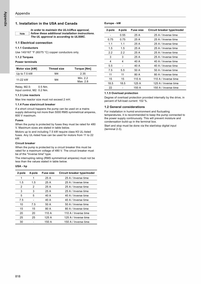
Appendix
818
Appendix
1. Installation in the USA and Canada
1.1 Electrical connection
1.1.1 Conductors
Use 140/167 °F (60/75 °C) copper conductors only.
1.1.2 Torques
Power terminals
Relay, M2.5: 0.5 Nm.Input control, M2: 0.2 Nm.
1.1.3 Line reactors
Max line reactor size must not exceed 2 mH.
1.1.4 Fuse size/circuit breaker
If a short circuit happens the pump can be used on a mains supply delivering not more than 5000 RMS symmetrical amperes, 600 V maximum.
Fuses
When the pump is protected by fuses they must be rated for 480 V. Maximum sizes are stated in table below.Motors up to and including 7.5 kW require class K5 UL-listed fuses. Any UL-listed fuse can be used for motors from 11 to 22 kW.
Circuit breaker
When the pump is protected by a circuit breaker this must be rated for a maximum voltage of 480 V. The circuit breaker must be of the "Inverse time" type.The interrupting rating (RMS symmetrical amperes) must not be less than the values stated in table below.
USA - hp
Europe - kW
1.1.5 Overload protection
Degree of overload protection provided internally by the drive, in percent of full-load current: 102 %.
1.2 General considerations
For installation in humid environment and fluctuating temperatures, it is recommended to keep the pump connected to the power supply continuously. This will prevent moisture and condensation build-up in the terminal box.Start and stop must be done via the start/stop digital input (terminal 2-3).
NoteIn order to maintain the UL/cURus approval, follow these additional installation instructions. The UL approval is according to UL508C.
Motor size [kW] Thread size Torque [Nm]
Up to 7.5 kW M4 2.35
11-22 kW M4 Min. 2.2Max. 2.8
2-pole 4-pole Fuse size Circuit breaker type/model
1 1 25 A 25 A / Inverse time1.5 1.5 25 A 25 A / Inverse time2 2 25 A 25 A / Inverse time3 3 25 A 25 A / Inverse time5 5 40 A 40 A / Inverse time
7.5 - 40 A 40 A / Inverse time10 7.5 50 A 50 A / Inverse time15 15 80 A 80 A / Inverse time20 20 110 A 110 A / Inverse time25 25 125 A 125 A / Inverse time30 - 150 A 150 A / Inverse time
2-pole 4-pole Fuse size Circuit breaker type/model
- 0.55 25 A 25 A / Inverse time0.75 0.75 25 A 25 A / Inverse time1.1 1.1 25 A 25 A / Inverse time1.5 1.5 25 A 25 A / Inverse time2.2 2.2 25 A 25 A / Inverse time3 3 25 A 25 A / Inverse time4 4 40 A 40 A / Inverse time
5.5 - 40 A 40 A / Inverse time7.5 5.5 50 A 50 A / Inverse time11 11 80 A 80 A / Inverse time15 15 110 A 110 A / Inverse time
18.5 18.5 125 A 125 A / Inverse time22 - 150 A 150 A / Inverse time
Gru
nd
fos
co
mp
anie
s
ArgentinaBombas GRUNDFOS de Argentina S.A.Ruta Panamericana km. 37.500 Centro Industrial Garin1619 Garín Pcia. de B.A.Phone: +54-3327 414 444Telefax: +54-3327 45 3190
AustraliaGRUNDFOS Pumps Pty. Ltd. P.O. Box 2040 Regency Park South Australia 5942 Phone: +61-8-8461-4611 Telefax: +61-8-8340 0155
AustriaGRUNDFOS Pumpen Vertrieb Ges.m.b.H.Grundfosstraße 2 A-5082 Grödig/Salzburg Tel.: +43-6246-883-0 Telefax: +43-6246-883-30
BelgiumN.V. GRUNDFOS Bellux S.A. Boomsesteenweg 81-83 B-2630 Aartselaar Tél.: +32-3-870 7300 Télécopie: +32-3-870 7301
BelarusПредставительство ГРУНДФОС в Минске220125, Минскул. Шафарнянская, 11, оф. 56, БЦ «Порт»Тел.: +375 17 397 397 3
+375 17 397 397 4Факс: +375 17 397 397 1E-mail: [email protected]
Bosnia and HerzegovinaGRUNDFOS SarajevoZmaja od Bosne 7-7A,BH-71000 SarajevoPhone: +387 33 592 480Telefax: +387 33 590 465www.ba.grundfos.come-mail: [email protected]
BrazilBOMBAS GRUNDFOS DO BRASILAv. Humberto de Alencar Castelo Branco, 630CEP 09850 - 300São Bernardo do Campo - SPPhone: +55-11 4393 5533Telefax: +55-11 4343 5015
BulgariaGrundfos Bulgaria EOODSlatina DistrictIztochna Tangenta street no. 100BG - 1592 SofiaTel. +359 2 49 22 200Fax. +359 2 49 22 201email: [email protected]
CanadaGRUNDFOS Canada Inc. 2941 Brighton Road Oakville, Ontario L6H 6C9 Phone: +1-905 829 9533 Telefax: +1-905 829 9512
ChinaGRUNDFOS Pumps (Shanghai) Co. Ltd.10F The Hub, No. 33 Suhong RoadMinhang DistrictShanghai 201106PRCPhone: +86 21 612 252 22Telefax: +86 21 612 253 33
COLOMBIAGRUNDFOS Colombia S.A.S.Km 1.5 vía Siberia-Cota Conj. Potrero Chico,Parque Empresarial Arcos de Cota Bod. 1A.Cota, CundinamarcaPhone: +57(1)-2913444Telefax: +57(1)-8764586
CroatiaGRUNDFOS CROATIA d.o.o.Buzinski prilaz 38, BuzinHR-10010 ZagrebPhone: +385 1 6595 400 Telefax: +385 1 6595 499www.hr.grundfos.com
GRUNDFOS Sales Czechia and Slovakia s.r.o.Čajkovského 21779 00 OlomoucPhone: +420-585-716 111
DenmarkGRUNDFOS DK A/S Martin Bachs Vej 3 DK-8850 Bjerringbro Tlf.: +45-87 50 50 50 Telefax: +45-87 50 51 51 E-mail: [email protected]/DK
EstoniaGRUNDFOS Pumps Eesti OÜPeterburi tee 92G11415 TallinnTel: + 372 606 1690Fax: + 372 606 1691
FinlandOY GRUNDFOS Pumput AB Trukkikuja 1 FI-01360 Vantaa Phone: +358-(0) 207 889 500
FrancePompes GRUNDFOS Distribution S.A. Parc d’Activités de Chesnes 57, rue de Malacombe F-38290 St. Quentin Fallavier (Lyon) Tél.: +33-4 74 82 15 15 Télécopie: +33-4 74 94 10 51
GermanyGRUNDFOS GMBHSchlüterstr. 3340699 ErkrathTel.: +49-(0) 211 929 69-0 Telefax: +49-(0) 211 929 69-3799e-mail: [email protected] in Deutschland:e-mail: [email protected]
GreeceGRUNDFOS Hellas A.E.B.E. 20th km. Athinon-Markopoulou Av. P.O. Box 71 GR-19002 Peania Phone: +0030-210-66 83 400 Telefax: +0030-210-66 46 273
Hong KongGRUNDFOS Pumps (Hong Kong) Ltd. Unit 1, Ground floor Siu Wai Industrial Centre 29-33 Wing Hong Street & 68 King Lam Street, Cheung Sha Wan Kowloon Phone: +852-27861706 / 27861741 Telefax: +852-27858664
HungaryGRUNDFOS Hungária Kft.Tópark u. 8H-2045 Törökbálint, Phone: +36-23 511 110Telefax: +36-23 511 111
IndiaGRUNDFOS Pumps India Private Limited118 Old Mahabalipuram RoadThoraipakkamChennai 600 096Phone: +91-44 2496 6800
IndonesiaPT. GRUNDFOS POMPAGraha Intirub Lt. 2 & 3Jln. Cililitan Besar No.454. Makasar, Jakarta TimurID-Jakarta 13650Phone: +62 21-469-51900Telefax: +62 21-460 6910 / 460 6901
IrelandGRUNDFOS (Ireland) Ltd. Unit A, Merrywell Business ParkBallymount Road LowerDublin 12 Phone: +353-1-4089 800 Telefax: +353-1-4089 830
ItalyGRUNDFOS Pompe Italia S.r.l. Via Gran Sasso 4I-20060 Truccazzano (Milano)Tel.: +39-02-95838112 Telefax: +39-02-95309290 / 95838461
JapanGRUNDFOS Pumps K.K.1-2-3, Shin-Miyakoda, Kita-ku, Hamamatsu431-2103 JapanPhone: +81 53 428 4760Telefax: +81 53 428 5005
KoreaGRUNDFOS Pumps Korea Ltd.6th Floor, Aju Building 679-5Yeoksam-dong, Kangnam-ku, 135-916Seoul, KoreaPhone: +82-2-5317 600Telefax: +82-2-5633 725
LatviaSIA GRUNDFOS Pumps Latvia Deglava biznesa centrsAugusta Deglava ielā 60, LV-1035, Rīga,Tālr.: + 371 714 9640, 7 149 641Fakss: + 371 914 9646
LithuaniaGRUNDFOS Pumps UABSmolensko g. 6LT-03201 VilniusTel: + 370 52 395 430Fax: + 370 52 395 431
MalaysiaGRUNDFOS Pumps Sdn. Bhd.7 Jalan Peguam U1/25Glenmarie Industrial Park40150 Shah AlamSelangor Phone: +60-3-5569 2922Telefax: +60-3-5569 2866
MexicoBombas GRUNDFOS de México S.A. de C.V. Boulevard TLC No. 15Parque Industrial Stiva AeropuertoApodaca, N.L. 66600Phone: +52-81-8144 4000 Telefax: +52-81-8144 4010
NetherlandsGRUNDFOS NetherlandsVeluwezoom 351326 AE AlmerePostbus 220151302 CA ALMERE Tel.: +31-88-478 6336 Telefax: +31-88-478 6332E-mail: [email protected]
New ZealandGRUNDFOS Pumps NZ Ltd.17 Beatrice Tinsley CrescentNorth Harbour Industrial EstateAlbany, AucklandPhone: +64-9-415 3240Telefax: +64-9-415 3250
NorwayGRUNDFOS Pumper A/S Strømsveien 344 Postboks 235, Leirdal N-1011 Oslo Tlf.: +47-22 90 47 00 Telefax: +47-22 32 21 50
PolandGRUNDFOS Pompy Sp. z o.o.ul. Klonowa 23Baranowo k. PoznaniaPL-62-081 PrzeźmierowoTel: (+48-61) 650 13 00Fax: (+48-61) 650 13 50
PortugalBombas GRUNDFOS Portugal, S.A. Rua Calvet de Magalhães, 241Apartado 1079P-2770-153 Paço de ArcosTel.: +351-21-440 76 00Telefax: +351-21-440 76 90
RomaniaGrundfos Pompe România SRLS-PARK BUSINESS CENTER, Clădirea A2,etaj 2, Str. Tipografilor, Nr. 11-15, Sector 1,Cod 013714, Bucuresti, Romania,Tel: 004 021 2004 100E-mail: [email protected]
RussiaООО Грундфос Россияул. Школьная, 39-41Москва, RU-109544, Russia Тел. (+7) 495 564-88-00 (495) 737-30-00Факс (+7) 495 564 8811E-mail [email protected]
Serbia Grundfos Srbija d.o.o.Omladinskih brigada 90b11070 Novi Beograd Phone: +381 11 2258 740Telefax: +381 11 2281 769www.rs.grundfos.com
SingaporeGRUNDFOS (Singapore) Pte. Ltd.25 Jalan Tukang Singapore 619264 Phone: +65-6681 9688 Telefax: +65-6681 9689
SlovakiaGRUNDFOS s.r.o.Prievozská 4D 821 09 BRATISLAVA Phona: +421 2 5020 1426sk.grundfos.com
SloveniaGRUNDFOS LJUBLJANA, d.o.o.Leskoškova 9e, 1122 LjubljanaPhone: +386 (0) 1 568 06 10Telefax: +386 (0)1 568 06 19E-mail: [email protected]
South AfricaGrundfos (PTY) Ltd.16 Lascelles Drive, Meadowbrook Estate1609 Germiston, JohannesburgTel.: (+27) 10 248 6000Fax: (+27) 10 248 6002E-mail: [email protected]
SpainBombas GRUNDFOS España S.A. Camino de la Fuentecilla, s/n E-28110 Algete (Madrid) Tel.: +34-91-848 8800 Telefax: +34-91-628 0465
SwedenGRUNDFOS AB Box 333 (Lunnagårdsgatan 6) 431 24 Mölndal Tel.: +46 31 332 23 000Telefax: +46 31 331 94 60
SwitzerlandGRUNDFOS Pumpen AG Bruggacherstrasse 10 CH-8117 Fällanden/ZH Tel.: +41-44-806 8111 Telefax: +41-44-806 8115
TaiwanGRUNDFOS Pumps (Taiwan) Ltd. 7 Floor, 219 Min-Chuan Road Taichung, Taiwan, R.O.C. Phone: +886-4-2305 0868Telefax: +886-4-2305 0878
ThailandGRUNDFOS (Thailand) Ltd. 92 Chaloem Phrakiat Rama 9 Road,Dokmai, Pravej, Bangkok 10250Phone: +66-2-725 8999Telefax: +66-2-725 8998
TurkeyGRUNDFOS POMPA San. ve Tic. Ltd. Sti.Gebze Organize Sanayi Bölgesi Ihsan dede Caddesi,2. yol 200. Sokak No. 20441490 Gebze/ KocaeliPhone: +90 - 262-679 7979Telefax: +90 - 262-679 7905E-mail: [email protected]
UkraineБізнес Центр ЄвропаСтоличне шосе, 103м. Київ, 03131, Україна Телефон: (+38 044) 237 04 00 Факс.: (+38 044) 237 04 01E-mail: [email protected]
United Arab EmiratesGRUNDFOS Gulf DistributionP.O. Box 16768Jebel Ali Free ZoneDubaiPhone: +971 4 8815 166Telefax: +971 4 8815 136
United KingdomGRUNDFOS Pumps Ltd. Grovebury Road Leighton Buzzard/Beds. LU7 4TL Phone: +44-1525-850000 Telefax: +44-1525-850011
U.S.A.GRUNDFOS Pumps Corporation 9300 Loiret Blvd.Lenexa, Kansas 66219Phone: +1-913-227-3400 Telefax: +1-913-227-3500
UzbekistanGrundfos Tashkent, Uzbekistan The Repre-sentative Office of Grundfos Kazakhstan in Uzbekistan38a, Oybek street, TashkentТелефон: (+998) 71 150 3290 / 71 150 3291Факс: (+998) 71 150 3292
Addresses Revised 09.09.2020

96782376 04.2021
ECM: 1310103 Trad
emar
ks d
ispl
ayed
in th
is m
ater
ial,
incl
udin
g bu
t not
lim
ited
to G
rund
fos,
the
Gru
ndfo
s lo
go a
nd “b
e th
ink
inno
vate
” are
regi
ster
ed tr
adem
arks
ow
ned
by T
he G
rund
fos
Gro
up. A
ll rig
hts
rese
rved
.©
202
1 G
rund
fos
Hol
ding
A/S
, all
right
s re
serv
ed.
www.grundfos.com