tpic - 2007 - design
TRANSCRIPT

TPIC - 2007
Truss Plate Institute of Canada
TRUSS DESIGN PROCEDURES AND SPECIFICATIONS
FOR LIGHT METAL PLATE CONNECTED WOOD TRUSSES
Limit States Design

TTRRUUSSSS PPLLAATTEE IINNSSTTIITTUUTTEE OOFF CCAANNAADDAA ((22000077))
JJuunnee ’’0077 ii
TRUSS PLATE INSTITUTE OF CANADA (TPIC)TRUSS PLATE INSTITUTE OF CANADA (TPIC)
FFuullll MMeemmbbeerrss::
AAllppiinnee SSyysstteemmss CCoorrppoorraattiioonn 11770011 CCrreeddiittssttoonnee RRdd.. CCoonnccoorrdd,, OOnnttaarriioo LL44KK 55VV66
MMiiTTeekk CCaannaaddaa,, IInncc.. 110000 IInndduussttrriiaall RRooaadd BBrraaddffoorrdd,, OOnnttaarriioo LL33ZZ 22BB77
JJaaggeerr MMeettaall PPrroodduuccttss IInncc.. 99441155--4488 SSttrreeeett.. SS..EE.. CCaallggaarryy,, AAllbbeerrttaa TT22CC 22RR11
SSyysstteemmeess FFoorreeTTrruussss IInncc.. 117799 BBllvvdd DDee LL''AAeerrooppoorrtt GGaattiinneeaauu,, QQuueebbeecc JJ88PP 77GG77
LLoonnddoonn RRooooff TTrruussss IInncc.. 11994411 GGoorree RRooaadd LLoonnddoonn,, OOnnttaarriioo NN55WW 66BB99
AAssssoocciiaatteedd MMeemmbbeerrss :: SSttrraaccoonn EEnnggiinneeeerriinngg IInncc.. 6699 GGrraayyddoonn CCrreess..,, RRiicchhmmoonndd HHiillll,, OOnnttaarriioo,, LL44BB 33WW77
EEttrruussss EEnnggiinneeeerriinngg 443399 SSuummmmeerriiddggee DDrriivvee TThhoorrnnhhiillll,, OOnnttaarriioo LL44JJ 99HH11
CCoorrppoorraattee MMeemmbbeerrss :: SSiimmppssoonn SSttrroonngg--TTiiee CCaannaaddaa,, LLttdd.. 1111447766 KKiinnggssttoonn SSttrreeeett MMaappllee RRiiddggee,, BBrriittiisshh CCoolluummbbiiaa VV22XX 00YY55
RReennoowwnn SSppeecciiaallttiieess CCoo.. LLttdd.. 222211 RRaaccccoo PPaarrkkwwaayy TThhoorrnnhhiillll,, OOnnttaarriioo LL44JJ 88XX99
AAffffiilliiaattee MMeemmbbeerrss :: AAQQFFSSBB PPOO BBooxx 11001100 VViiccttoorriiaavviillllee,, QQuuéébbeecc GG66PP 88YY11
AAWWTTFFAA 998899,, RRoouuttee 660055 MMaappllee RRiiddggee,, NNeeww BBrruunnsswwiicckk EE66EE 11WW77
OOWWTTFFAA cc//oo KKeenntt TTrruusssseess 110022 CCoommmmeerrccee PPaarrkk DDrriivvee BBaarrrriiee,, OOnnttaarriioo LL44NN 88WW88
WWWWTTAABBCC 880022 WWaasshhiinnggttoonn DDrriivvee,, PPoorrtt MMooooddyy,, BBrriittiisshh CCoolluummbbiiaa VV33HH 33KK88
WWWWTTAA--MMBB,, SSKK 337700 LLaauurreell BBaayy OOaakkbbaannkk,, MMaanniittoobbaa RR00EE 11JJ11
WWWWTTAAAA 114488 DDoouuggllaass PPaarrkk CClloossee SSEE CCaallggaarryy,, AAllbbeerrttaa TT22ZZ 22AA88
TTRRUUSSSS PPLLAATTEE IINNSSTTIITTUUTTEE OOFF CCAANNAADDAA ((22000077))
JJuunnee ’’0077 iiii
DISCLAIMER These recommendations are for the design of metal plate connected wood trusses that originate from the collective experience of leading technical personnel in the metal plate connected wood truss industry, but must, due to the nature of the responsibilities involved, be presented only as a guide for the use of a qualified engineer or designer. By publishing this booklet, the Truss Plate Institute of Canada and its member companies do not warrant the recommendations information contained herein as proper under all conditions and expressly disclaim any responsibility for damages arising from the use, application, or reliance on the recommendations and information contained herein. This standard does not preclude the use of materials, assemblies, structures or designs not meeting the criteria herein, when they demonstrate equivalent performance for the intended use to those specified in this standard.
TTRRUUSSSS PPLLAATTEE IINNSSTTIITTUUTTEE OOFF CCAANNAADDAA ((22000077))
JJuunnee ’’0077 iiiiii
FOREWARD The purpose of this manual is to present data for design to those familiar with engineering procedures. It does not include information found in standard engineering textbooks which include derivation of formulas. It is not intended that these specifications illustrate all truss configurations or details thereof.
This specification covers materials, both lumber and steel, design procedures for members and joints, including minimum snow loads and minimum dead loads, and evaluation of connector plates.
This specification incorporates the most recent code changes, lumber and design standards and the latest generally accepted engineering procedures and methods. All previous editions of this specification are obsolete.
These specifications do not cover design for the complete structural system of a building. Suitable provisions must be made for adequate supports, cross bracing, wind loading, seismic loading, or other horizontal loading by those responsible for over-all building design.
The design methods contained within this specification are based on sound engineering judgement with specific reference to the Canadian Standards Association (CSA 086-01 and 086S1-05) and the National Building Code of Canada 2005. A continuous program of research work is being carried out at various universities and testing laboratories to supplement and enhance this specification.
The purpose of the Truss Plate Institute of Canada is; to serve the needs of manufacturers of truss plates and wood trusses by representation on various committees of recognized organizations dealing with building codes and standards; to establish and promulgate standards for the design, manufacture and quality control of truss plates as may be required; to do all other things to foster and develop truss plate manufacturing and wood truss fabrication industries, consistent with law, and in the mutual interest of members of the organization.
HISTORY OF TPIC Year 1971 National Building Code of Canada (1970) introduced new classifications and dimensions for lumber construction.
June 1971 Several major Canadian truss plate manufacturers convened for the purpose of creating the Truss Plate Institute of Canada.
May 1972 TPIC was incorporated under Canadian law and its constitution and by-laws adopted.
July 1973 Uniform testing procedures for metal truss plates were developed.
April 1974 CMHC and TPIC agreed on maximum span tables for publication in N.B.C.C.
Oct 1976 TPIC Testing procedures for truss plates were adopted as CSA Standard S347.
May 1977 CMHC recoginized TPIC Design Procedures.
Jan 1981 3rd Edition of TPIC Design Procedure for Roof and Floor Trusses published.
Jan 1988 4th Edition of TPIC Design Procedure for Roof and Floor Trusses published.
1988 - 1995 A number of addendums, revisions and additional design procedures were added to TPIC 1988 to keep the industry abreast of the lastest technical information.
Nov 1995 The publication, printing and distribution of the National Building Code of Canada introduces Reliability Based design procedures (Limit States design procedures). With Working Stress design procedures to be eliminated, truss testing at Forintek in Vancouver took place through 1993-1995.
Fall 1997 TPIC 1996 is published introducing truss design procedures and specifications for light metal plate connected wood trusses for Limit States Design.
Fall 2005 The publication, printing and distribution of the National Building Code of Canada brings about changes in loading Considerations
June 2007 TPIC 2007 is published updating the document to incorparate changes brought about by NBCC 2005 and considerations for OBC 2006.
TTRRUUSSSS PPLLAATTEE IINNSSTTIITTUUTTEE OOFF CCAANNAADDAA ((22000077))
iivv
DESIGN RESPONSIBILITIES Truss Designer/Engineer - a design professional, individual or organization having responsibility for the design of individual metal plate connected wood truss components, including lateral bracing requirements to prevent buckling of individual truss members due to specified loads. Building Designer/Engineer - a design professional, individual or organization, having responsibility for overall building design. Within the scope of wood trusses, the building designer / engineer, shall specify the following: (a) Design loads in occordance with various sections of the National and / or Provincial Building
Codes. (b) Truss profile and intended support locations. (c) Vertical and horizontal deflection limits. (d) Moisture enviroment for intended end use. (e) Any special requirements to be considered in the truss design. (f) Additional loads from mechanical, electrical units, which may induce extra load to various truss
members and their locations. As this standard does not cover the design for the complete structural system of a building, the building designer / engineer shall provide the following in the design and detailing of the building: (a) Truss supports and anchorage accommodating horizontal, vertical or other reaction or
displacement. (b) Permanent truss bracing to resist wind, seismic and any other lateral forces acting parallel or
perdendicular to the plane of trusses. (c) Method of connection or anchorage of mechanical, electrical units to various truss members.
TRUSS PLATE INSTITUTE OF CANADA (2007)
CONTENTS 1. GENERAL 1
1.1 Definitions 1 1.2 Abbreviations 2 1.3 Reference Publications 3
2. MATERIALS 4 2.1 Lumber Sizes and Grades 4 2.2 Steel 4
3. GENERAL DESIGN 6 3.1 Specified Loads, Load Effects and Load Combinations 6
3.1.1 Buildings 6 3.1.2 Specified Loads 6
3.1.2.1 Loads to be Considered 3.1.2.2 Importance Category 6 3.1.2.3 Importance Factors 7
3.1.3 Load Combinations 8 3.1.3.1 Load Combinations for Ultimate Limit States 8 3.1.3.2 Load Combinations for Serviceability Limit States 8
3.2 Specified Snow, Live and Wind Loads 9 3.2.1 Roof Trusses – Housing and Small Buildings (Part 9 of NBCC05) 9 3.2.2 Roof Trusses (Part 4 of NBCC05) 9 3.2.3 Low Human Occupancy (Farm) 10 3.2.4 Floor Trusses – Housing and Small Buildings (Part 9 of NBCC05) 10 3.2.5 Floor Trusses (Part 4 of NBCC05) 10
3.3 Specified Dead Loads 11 3.3.1 Roof Dead Loads 11 3.3.2 Floor Dead Loads 11
4. MEMBER DESIGN PROCEDURE 12
4.1 Analogue 12 4.1.1 Analogue Joint Types 12 4.1.2 Analogue Points 12 4.1.3 Analogue Modifications 14
4.2 Ultimate Limit States 23 4.2.1 Method of Analysis 23 4.2.2 Ultimate Limit States 23
4.3 Specified Strengths 24 4.3.1 Visually Stress-Graded Lumber 24 4.3.2 Machine Stress-Rated and Machine Evaluated Lumber 24 4.3.3 Design Specified Strengths 24 4.3.4 Modification Factors 24
4.4 Strength and Resistance 27 4.4.1 Bending Moment Resistance 27 4.4.2 Shear Resistance 27 4.4.3 Compressive Resistance Parallel To Grain 28 4.4.4 Compressive Resistance Perpendicular To Grain 29 4.4.5 Tensile Resistance Parallel To Grain 30 4.4.6 Stress Index Due To Bending 30 4.4.7 Stress Index Due To Shear 30 4.4.8 Stress Index To Compression (Parallel to Grain) 31
June ’07 v
TRUSS PLATE INSTITUTE OF CANADA (2007)
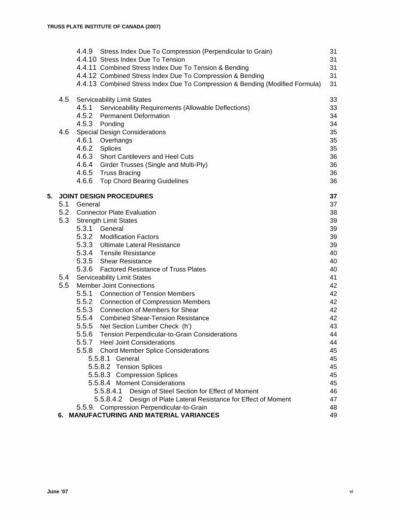
4.4.9 Stress Index Due To Compression (Perpendicular to Grain) 31 4.4.10 Stress Index Due To Tension 31 4.4.11 Combined Stress Index Due To Tension & Bending 31 4.4.12 Combined Stress Index Due To Compression & Bending 31 4.4.13 Combined Stress Index Due To Compression & Bending (Modified Formula) 31
4.5 Serviceability Limit States 33 4.5.1 Serviceability Requirements (Allowable Deflections) 33 4.5.2 Permanent Deformation 34 4.5.3 Ponding 34
4.6 Special Design Considerations 35 4.6.1 Overhangs 35 4.6.2 Splices 35 4.6.3 Short Cantilevers and Heel Cuts 36 4.6.4 Girder Trusses (Single and Multi-Ply) 36 4.6.5 Truss Bracing 36 4.6.6 Top Chord Bearing Guidelines 36
5. JOINT DESIGN PROCEDURES 37 5.1 General 37 5.2 Connector Plate Evaluation 38 5.3 Strength Limit States 39
5.3.1 General 39 5.3.2 Modification Factors 39 5.3.3 Ultimate Lateral Resistance 39 5.3.4 Tensile Resistance 40 5.3.5 Shear Resistance 40 5.3.6 Factored Resistance of Truss Plates 40
5.4 Serviceability Limit States 41 5.5 Member Joint Connections 42
5.5.1 Connection of Tension Members 42 5.5.2 Connection of Compression Members 42 5.5.3 Connection of Members for Shear 42 5.5.4 Combined Shear-Tension Resistance 42 5.5.5 Net Section Lumber Check (h’) 43 5.5.6 Tension Perpendicular-to-Grain Considerations 44 5.5.7 Heel Joint Considerations 44 5.5.8 Chord Member Splice Considerations 45
5.5.8.1 General 45 5.5.8.2 Tension Splices 45 5.5.8.3 Compression Splices 45 5.5.8.4 Moment Considerations 45
5.5.8.4.1 Design of Steel Section for Effect of Moment 46 5.5.8.4.2 Design of Plate Lateral Resistance for Effect of Moment 47
5.5.9. Compression Perpendicular-to-Grain 48 6. MANUFACTURING AND MATERIAL VARIANCES 49
June ’07 vi
TRUSS PLATE INSTITUTE OF CANADA (2007)
APPENDIX
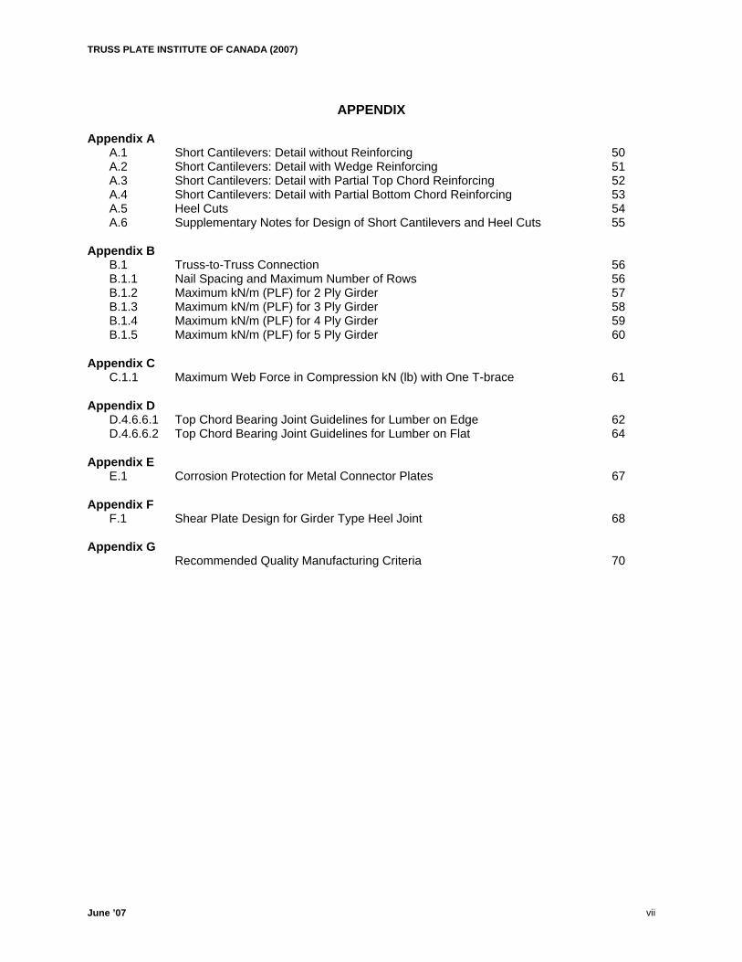
Appendix A
A.1 Short Cantilevers: Detail without Reinforcing 50 A.2 Short Cantilevers: Detail with Wedge Reinforcing 51 A.3 Short Cantilevers: Detail with Partial Top Chord Reinforcing 52 A.4 Short Cantilevers: Detail with Partial Bottom Chord Reinforcing 53 A.5 Heel Cuts 54 A.6 Supplementary Notes for Design of Short Cantilevers and Heel Cuts 55
Appendix B B.1 Truss-to-Truss Connection 56 B.1.1 Nail Spacing and Maximum Number of Rows 56 B.1.2 Maximum kN/m (PLF) for 2 Ply Girder 57 B.1.3 Maximum kN/m (PLF) for 3 Ply Girder 58 B.1.4 Maximum kN/m (PLF) for 4 Ply Girder 59 B.1.5 Maximum kN/m (PLF) for 5 Ply Girder 60
Appendix C
C.1.1 Maximum Web Force in Compression kN (lb) with One T-brace 61 Appendix D
D.4.6.6.1 Top Chord Bearing Joint Guidelines for Lumber on Edge 62 D.4.6.6.2 Top Chord Bearing Joint Guidelines for Lumber on Flat 64
Appendix E
E.1 Corrosion Protection for Metal Connector Plates 67 Appendix F
F.1 Shear Plate Design for Girder Type Heel Joint 68
Appendix G Recommended Quality Manufacturing Criteria 70
June ’07 vii
TRUSS PLATE INSTITUTE OF CANADA (2007)
ILLUSTRATIONS
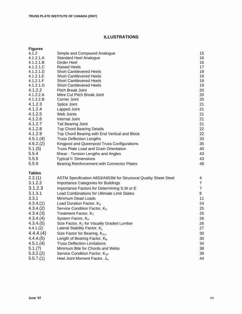
Figures 4.1.2 Simple and Compound Analogue 15 4.1.2.1.A Standard Heel Analogue 16 4.1.2.1.B Girder Heel 16 4.1.2.1.C Raised Heels 17 4.1.2.1.D Short Cantilevered Heels 18 4.1.2.1.E Short Cantilevered Heels 19 4.1.2.1.F Short Cantilevered Heels 19 4.1.2.1.G Short Cantilevered Heels 19 4.1.2.2 Pitch Break Joint 20 4.1.2.2.A Mitre Cut Pitch Break Joint 20 4.1.2.2.B Corner Joint 20 4.1.2.3 Splice Joint 21 4.1.2.4 Lapped Joint 21 4.1.2.5 Web Joints 21 4.1.2.6 Internal Joint 21 4.1.2.7 Tail Bearing Joint 21 4.1.2.8 Top Chord Bearing Details 22 4.1.2.9 Top Chord Bearing with End Vertical and Block 22 4.5.1.(4) Truss Deflection Lengths 33 4.6.2.(2) Kingpost and Queenpost Truss Configurations 35 5.1.(5) Truss Plate Load and Grain Orientation 40 5.5.4 Shear - Tension Lengths and Angles 43 5.5.5 Typical h’ Dimensions 43 5.5.9 Bearing Reinforcement with Connector Plates 48 Tables 2.2.(1) ASTM Specification A653/A653M for Structural Quality Sheet Steel 4 3.1.2.2 Importance Categories for Buildings 7 3.1.2.3 Importance Factors for Determining S,W or E 7 3.1.3.1 Load Combinations for Ultimate Limit States 8 3.3.1 Minimum Dead Loads 11 4.3.4.(1) Load Duration Factor, KD 24
4.3.4.(2) Service Condition Factor, KS 25 4.3.4.(3) Treatment Factor, KT 25 4.3.4.(4) System Factor, KH 26 4.3.4.(5) Size Factor, KZ for Visually Graded Lumber 26 4.4.1.(2) Lateral Stability Factor, KL 27 4.4.4.(4) Size Factor for Bearing, KZCP 30 4.4.4.(5) Length of Bearing Factor, KB 30 B
4.5.1.(4) Truss Deflection Limitations 34 5.1.(7) Minimum Bite for Chords and Webs 38 5.3.2.(2) Service Condition Factor, KSF 39 5.5.7.(1) Heel Joint Moment Factor, JH 44
June ’07 viii
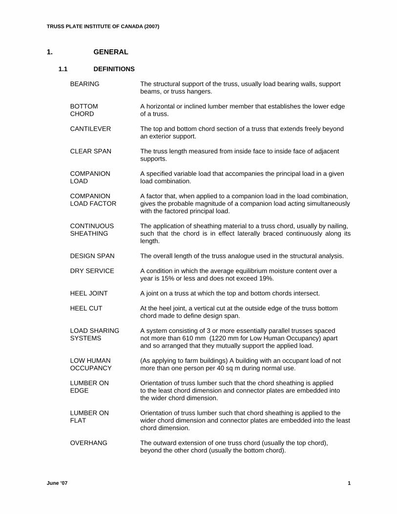
TRUSS PLATE INSTITUTE OF CANADA (2007) 1. GENERAL 1.1 DEFINITIONS BEARING The structural support of the truss, usually load bearing walls, support
beams, or truss hangers. BOTTOM A horizontal or inclined lumber member that establishes the lower edge CHORD of a truss. CANTILEVER The top and bottom chord section of a truss that extends freely beyond
an exterior support. CLEAR SPAN The truss length measured from inside face to inside face of adjacent
supports. COMPANION A specified variable load that accompanies the principal load in a given LOAD load combination.
COMPANION A factor that, when applied to a companion load in the load combination, LOAD FACTOR gives the probable magnitude of a companion load acting simultaneously with the factored principal load.
CONTINUOUS The application of sheathing material to a truss chord, usually by nailing, SHEATHING such that the chord is in effect laterally braced continuously along its
length. DESIGN SPAN The overall length of the truss analogue used in the structural analysis. DRY SERVICE A condition in which the average equilibrium moisture content over a
year is 15% or less and does not exceed 19%. HEEL JOINT A joint on a truss at which the top and bottom chords intersect. HEEL CUT At the heel joint, a vertical cut at the outside edge of the truss bottom
chord made to define design span. LOAD SHARING A system consisting of 3 or more essentially parallel trusses spaced SYSTEMS not more than 610 mm (1220 mm for Low Human Occupancy) apart
and so arranged that they mutually support the applied load. LOW HUMAN (As applying to farm buildings) A building with an occupant load of not OCCUPANCY more than one person per 40 sq m during normal use. LUMBER ON Orientation of truss lumber such that the chord sheathing is applied EDGE to the least chord dimension and connector plates are embedded into
the wider chord dimension. LUMBER ON Orientation of truss lumber such that chord sheathing is applied to the FLAT wider chord dimension and connector plates are embedded into the least
chord dimension. OVERHANG The outward extension of one truss chord (usually the top chord),
beyond the other chord (usually the bottom chord).
June ’07 1
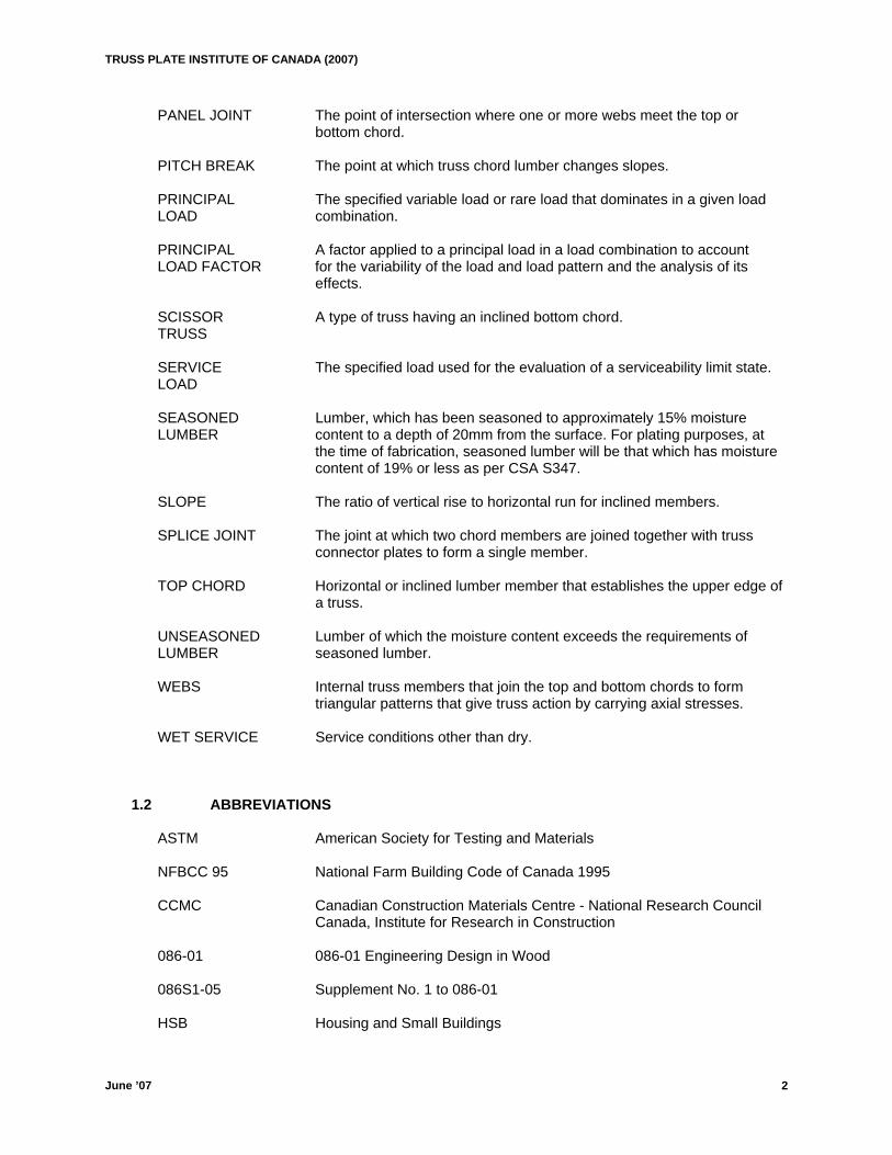
TRUSS PLATE INSTITUTE OF CANADA (2007) PANEL JOINT The point of intersection where one or more webs meet the top or
bottom chord. PITCH BREAK The point at which truss chord lumber changes slopes. PRINCIPAL The specified variable load or rare load that dominates in a given load LOAD combination. PRINCIPAL A factor applied to a principal load in a load combination to account LOAD FACTOR for the variability of the load and load pattern and the analysis of its
effects. SCISSOR A type of truss having an inclined bottom chord. TRUSS SERVICE The specified load used for the evaluation of a serviceability limit state. LOAD SEASONED Lumber, which has been seasoned to approximately 15% moisture LUMBER content to a depth of 20mm from the surface. For plating purposes, at
the time of fabrication, seasoned lumber will be that which has moisture content of 19% or less as per CSA S347.
SLOPE The ratio of vertical rise to horizontal run for inclined members. SPLICE JOINT The joint at which two chord members are joined together with truss
connector plates to form a single member. TOP CHORD Horizontal or inclined lumber member that establishes the upper edge of a truss. UNSEASONED Lumber of which the moisture content exceeds the requirements of LUMBER seasoned lumber.
WEBS Internal truss members that join the top and bottom chords to form triangular patterns that give truss action by carrying axial stresses. WET SERVICE Service conditions other than dry. 1.2 ABBREVIATIONS ASTM American Society for Testing and Materials NFBCC 95 National Farm Building Code of Canada 1995 CCMC Canadian Construction Materials Centre - National Research Council Canada, Institute for Research in Construction
086-01 086-01 Engineering Design in Wood
086S1-05 Supplement No. 1 to 086-01 HSB Housing and Small Buildings
June ’07 2
TRUSS PLATE INSTITUTE OF CANADA (2007) LHO Farm - Low Human Occupancy NBCC95 National Building Code of Canada 1995 NBCC05 National Building Code of Canada 2005 NBCC (ST.COMM.) Structural Commentaries on the National building Code of Canada, 1995 NBCC05 (ST.COMM) National Building Code of Canada 2005, Users Guide and Structural
Commentaries NLGA National Lumber Grades Authority NRCC National Research Council of Canada TPIC Truss Plate Institute of Canada 1.3 REFERENCE PUBLICATIONS ASTM A 653/A 653 M “Specification for Steel Sheet, Zinc-Coated (Galvanized) or Zinc
- Iron Alloy - Coated (Galvannealed) by the Hot-Dip Process.”
ASTM A 924/A 924 M “Specification for General Requirements for Steel Sheet, Metallic
- Coated by the Hot - Dip Process.”
086-01 Canadian Standards Association Publication “086-01 Engineering Design in Wood (Limit States Design)”
S347-99 Canadian Standards Association Publication “S347-99 Method of Test
for Evaluation of Truss Plates Used in Lumber Joints” NFBCC 1995 National Research Council of Canada Publication "National Farm
Building Code of Canada 1995" NBCC 1995 National Research Council of Canada Publication “National Building
Code of Canada 1995” NBCC 2005 National Research Council of Canada Publication “National Building
Code of Canada 2005” NBCC (ST.COMM.) National Research Council of Canada Publication, “Structural
Commentaries on the National Building Code of Canada 1995" NBCC05 (ST.COMM.) National Research Council of Canada Publication, “National Building Code of Canada 2005, Users Guide and Structural Commentaries"
OBC2006 Ontario Building Code 2006: Ontario’s Building Code (O.Reg 350/06, as amended) and supplemental standards
TPIC 1996 Truss Design Procedures and Specifications for Light Metal Plate
Connected Wood Trusses Limit States Design
June ’07 3
TRUSS PLATE INSTITUTE OF CANADA (2007)
June ’07 4
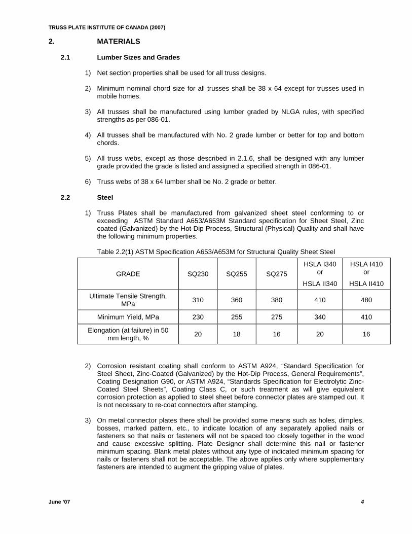
2. MATERIALS 2.1 Lumber Sizes and Grades 1) Net section properties shall be used for all truss designs. 2) Minimum nominal chord size for all trusses shall be 38 x 64 except for trusses used in
mobile homes. 3) All trusses shall be manufactured using lumber graded by NLGA rules, with specified
strengths as per 086-01. 4) All trusses shall be manufactured with No. 2 grade lumber or better for top and bottom
chords. 5) All truss webs, except as those described in 2.1.6, shall be designed with any lumber
grade provided the grade is listed and assigned a specified strength in 086-01. 6) Truss webs of 38 x 64 lumber shall be No. 2 grade or better. 2.2 Steel 1) Truss Plates shall be manufactured from galvanized sheet steel conforming to or
exceeding ASTM Standard A653/A653M Standard specification for Sheet Steel, Zinc coated (Galvanized) by the Hot-Dip Process, Structural (Physical) Quality and shall have the following minimum properties.
Table 2.2(1) ASTM Specification A653/A653M for Structural Quality Sheet Steel
GRADE SQ230 SQ255 SQ275 HSLA I340
or
HSLA II340
HSLA I410 or
HSLA II410
Ultimate Tensile Strength, MPa 310 360 380 410 480
Minimum Yield, MPa 230 255 275 340 410
Elongation (at failure) in 50 mm length, % 20 18 16 20 16
2) Corrosion resistant coating shall conform to ASTM A924, “Standard Specification for
Steel Sheet, Zinc-Coated (Galvanized) by the Hot-Dip Process, General Requirements”, Coating Designation G90, or ASTM A924, “Standards Specification for Electrolytic Zinc-Coated Steel Sheets”, Coating Class C, or such treatment as will give equivalent corrosion protection as applied to steel sheet before connector plates are stamped out. It is not necessary to re-coat connectors after stamping.
3) On metal connector plates there shall be provided some means such as holes, dimples,
bosses, marked pattern, etc., to indicate location of any separately applied nails or fasteners so that nails or fasteners will not be spaced too closely together in the wood and cause excessive splitting. Plate Designer shall determine this nail or fastener minimum spacing. Blank metal plates without any type of indicated minimum spacing for nails or fasteners shall not be acceptable. The above applies only where supplementary fasteners are intended to augment the gripping value of plates.
TRUSS PLATE INSTITUTE OF CANADA (2007)
June ’07 5
4) All plate manufacturers must have their plates listed in the Registry of Product
Evaluations published by Canadian Construction Materials Centre, Institute for Research in Construction, Ottawa, Ontario.
TRUSS PLATE INSTITUTE OF CANADA (2007)
June ’07 6
GENERAL DESIGN 3.1 Specified Loads, Load Effects, and Load Combinations
3.1.1 Buildings The specified loads, load effects and combinations to be considered in the design of a building and its elements shall be those given in Clauses 3.1.2 and 3.1.3.
3.1.2 Specified Loads 3.1.2.1 Loads to be Considered
Specified loads shall include the following wherever applicable, and minimum specified values of these loads shall be increased to account for dynamic effects where applicable:
(1) D --- dead load due to weight of members; the weight of all materials of construction incorporated into the building to be supported permanently by the member, including permanent partitions and allowance for nonpermanent partitions; the weight of permanent equipment;
(2) E --- load due to earthquake including the effect of the importance factors in 3.1.2.2;
(3) L --- live load due to intended use and occupancy including loads due to cranes and pressure of liquids in containers;
(4) S --- load due to snow, including ice and associated rain, and also including the effect of the importance factors in 3.1.1.2;
(5) W --- load due to wind including the importance factors in 3.1.2.2;
(6) H --- a permanent load due to lateral earth pressure, including groundwater;
(7) P --- permanent effects caused by prestress; and
(8) T --- loads due to contraction or expansion caused by temperature changes, shrinkage, moisture changes, creep in component materials, movement due to differential settlement, or combinations thereof.
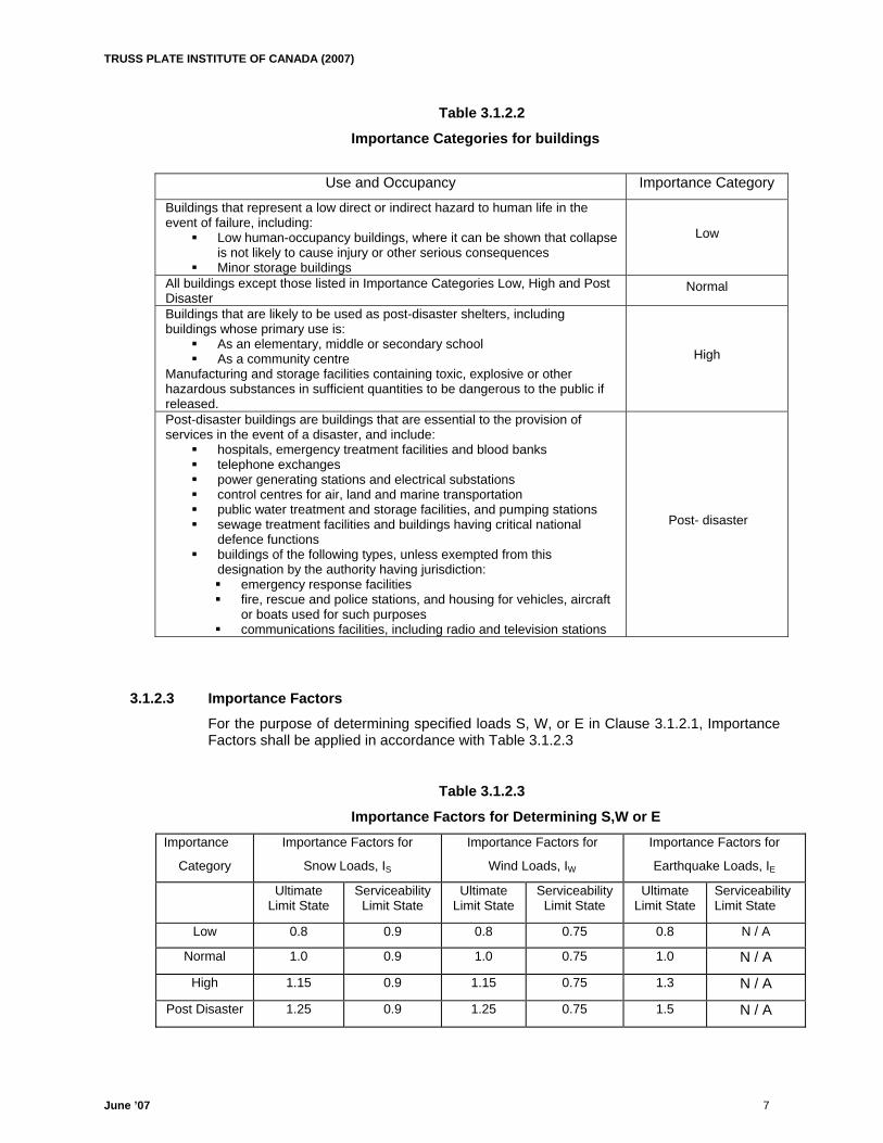
3.1.2.2 Importance Category For the purpose of determining specified loads S, W or E in Section 3.2.1 and 3.2.2, buildings shall be assigned an Importance Category based on intended use and occupancy, in accordance with table 3.1.2.2.
TRUSS PLATE INSTITUTE OF CANADA (2007)
June ’07 7
Table 3.1.2.2 Importance Categories for buildings
Use and Occupancy Importance Category
Buildings that represent a low direct or indirect hazard to human life in the event of failure, including:
Low human-occupancy buildings, where it can be shown that collapse is not likely to cause injury or other serious consequences
Minor storage buildings
Low
All buildings except those listed in Importance Categories Low, High and Post Disaster
Normal
Buildings that are likely to be used as post-disaster shelters, including buildings whose primary use is:
As an elementary, middle or secondary school As a community centre
Manufacturing and storage facilities containing toxic, explosive or other hazardous substances in sufficient quantities to be dangerous to the public if released.
High
Post-disaster buildings are buildings that are essential to the provision of services in the event of a disaster, and include:
hospitals, emergency treatment facilities and blood banks telephone exchanges power generating stations and electrical substations control centres for air, land and marine transportation public water treatment and storage facilities, and pumping stations sewage treatment facilities and buildings having critical national
defence functions buildings of the following types, unless exempted from this
designation by the authority having jurisdiction: emergency response facilities fire, rescue and police stations, and housing for vehicles, aircraft
or boats used for such purposes communications facilities, including radio and television stations
Post- disaster
3.1.2.3 Importance Factors
For the purpose of determining specified loads S, W, or E in Clause 3.1.2.1, Importance Factors shall be applied in accordance with Table 3.1.2.3
Table 3.1.2.3 Importance Factors for Determining S,W or E
Importance
Category Importance Factors for
Snow Loads, IS
Importance Factors for
Wind Loads, IW
Importance Factors for
Earthquake Loads, IE
Ultimate Limit State
Serviceability Limit State
Ultimate Limit State
Serviceability Limit State
Ultimate Limit State
Serviceability Limit State
Low 0.8 0.9 0.8 0.75 0.8 N / A
Normal 1.0 0.9 1.0 0.75 1.0 N / A
High 1.15 0.9 1.15 0.75 1.3 N / A
Post Disaster 1.25 0.9 1.25 0.75 1.5 N / A
TRUSS PLATE INSTITUTE OF CANADA (2007)
June ’07 8
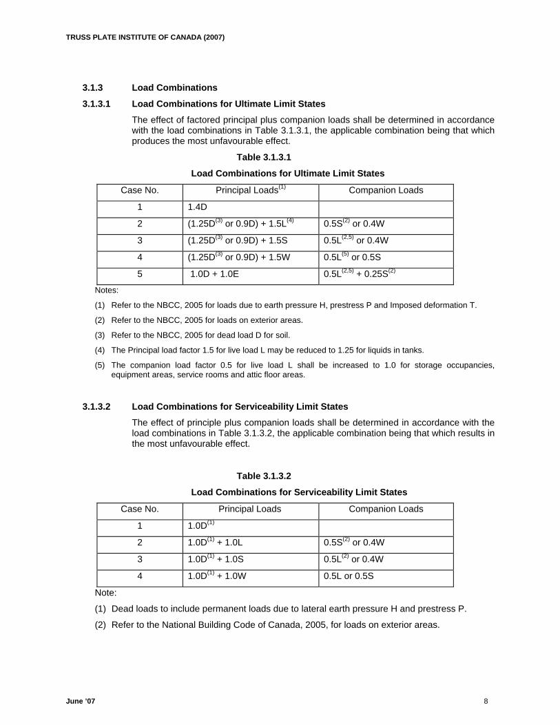
3.1.3 Load Combinations 3.1.3.1 Load Combinations for Ultimate Limit States The effect of factored principal plus companion loads shall be determined in accordance
with the load combinations in Table 3.1.3.1, the applicable combination being that which produces the most unfavourable effect.
Table 3.1.3.1 Load Combinations for Ultimate Limit States
Case No. Principal Loads(1) Companion Loads
1 1.4D
2 (1.25D(3) or 0.9D) + 1.5L(4) 0.5S(2) or 0.4W
3 (1.25D(3) or 0.9D) + 1.5S 0.5L(2,5) or 0.4W
4 (1.25D(3) or 0.9D) + 1.5W 0.5L(5) or 0.5S
5 1.0D + 1.0E 0.5L(2,5) + 0.25S(2)
Notes:
(1) Refer to the NBCC, 2005 for loads due to earth pressure H, prestress P and Imposed deformation T.
(2) Refer to the NBCC, 2005 for loads on exterior areas.
(3) Refer to the NBCC, 2005 for dead load D for soil.
(4) The Principal load factor 1.5 for live load L may be reduced to 1.25 for liquids in tanks.
(5) The companion load factor 0.5 for live load L shall be increased to 1.0 for storage occupancies, equipment areas, service rooms and attic floor areas.
3.1.3.2 Load Combinations for Serviceability Limit States
The effect of principle plus companion loads shall be determined in accordance with the load combinations in Table 3.1.3.2, the applicable combination being that which results in the most unfavourable effect.
Table 3.1.3.2 Load Combinations for Serviceability Limit States
Case No. Principal Loads Companion Loads
1 1.0D(1)
2 1.0D(1) + 1.0L 0.5S(2) or 0.4W
3 1.0D(1) + 1.0S 0.5L(2) or 0.4W
4 1.0D(1) + 1.0W 0.5L or 0.5S
Note:
(1) Dead loads to include permanent loads due to lateral earth pressure H and prestress P.
(2) Refer to the National Building Code of Canada, 2005, for loads on exterior areas.

TRUSS PLATE INSTITUTE OF CANADA (2007)
June ’07 9
3.2 Specified Snow, Live and Wind Loads 3.2.1 Roof Trusses – Housing and Small Buildings (Part 9 of NBCC05) 1) Roof trusses meeting the housing and small building requirements of Part 9 of the
NBCC05, with clear spans between bearings less than or equal to 12.19m, (40 feet) and a top chord slope ≥ 1/6, shall be designed using a roof snow load not less than 55% of the appropriate ground snow load plus rain load as listed in the NBCC05 Appendix C. When the entire width of roof does not exceed 4.3m (14 feet) this 55% can be reduced to 45%.
2) Roof trusses meeting the housing and small building requirements of Part 9 of the NBCC05, with clear spans between bearings greater than 12.19m (40 feet) or a top chord slope < 1/6 shall be designed as per Section 3.2.2.
3) The minimum specified top chord snow load shall be 1.0 kPa (21 psf) 4) Multi-bearing trusses shall be designed for pattern-loading. 5) Minimum bottom chord live load shall be 0.5 kPa (10 psf) for the Province of Ontario.
3.2.2 Roof Trusses (Part 4 of NBCC05) 1) Roof trusses designed under the requirements of Part 4 of NBCC05
shall be designed using a roof snow load not less than 80% of the appropriate ground snow load plus rain load as listed in NBCC05 Appendix C, except where:
(a) Wind exposure conditions specified by Section 4.1.6 of NBCC05 are fulfilled, hence 60% of the ground snow load plus rain load may be used as the roof snow load for low and normal building importance, or
(b) The roof slope is greater than 30 degrees, hence the roof snow load can be reduced by a slope factor as specified by Section 4.1.6 of NBCC05, or
(c) The roof slope is greater than 15 degrees and slippery roof conditions specified by Section 4.1.6 of NBCC05 are fulfilled, hence the roof snow load can be reduced by a slope factor as specified in that Section, or
(d) For large roofs the value of Cb shall be calculated as per NBCC05 4.1.6.2, 2) a) & b). (e) The snow load is specified in writing by an authority having jurisdiction.
2) Roof trusses shall be designed to meet the requirements of full and partial loading as specified by Section 4.1.5 and 4.1.6 of NBCC05.
3) Roof trusses shall be designed to meet the requirements of unbalanced, sliding and drifting snow loads, as given in Section 4.1.6 of the NBCC05.
4) Roof trusses with slopes of 15 degrees or less need not be designed for unbalanced snow loads.
5) The minimum specified top chord snow load shall be 1.0 kPa. (21 psf)
6) The minimum specified live load for attics with limited accessibility shall be .5 kPa (10 psf) as per Table 4.1.5.3 NBCC05 unless specified otherwise by an authority having jurisdiction.
7) Roof trusses shall be designed for wind loading in accordance with Section 4.1.7 NBCC05.
8) For wind analysis the minimum reference velocity pressure shall be based on the
probability of being exceeded once in 50 years for strength and deflection. Appropriate wind loads are as listed in NBCC05 Division B, Appendix C.
TRUSS PLATE INSTITUTE OF CANADA (2007)
June ’07 10
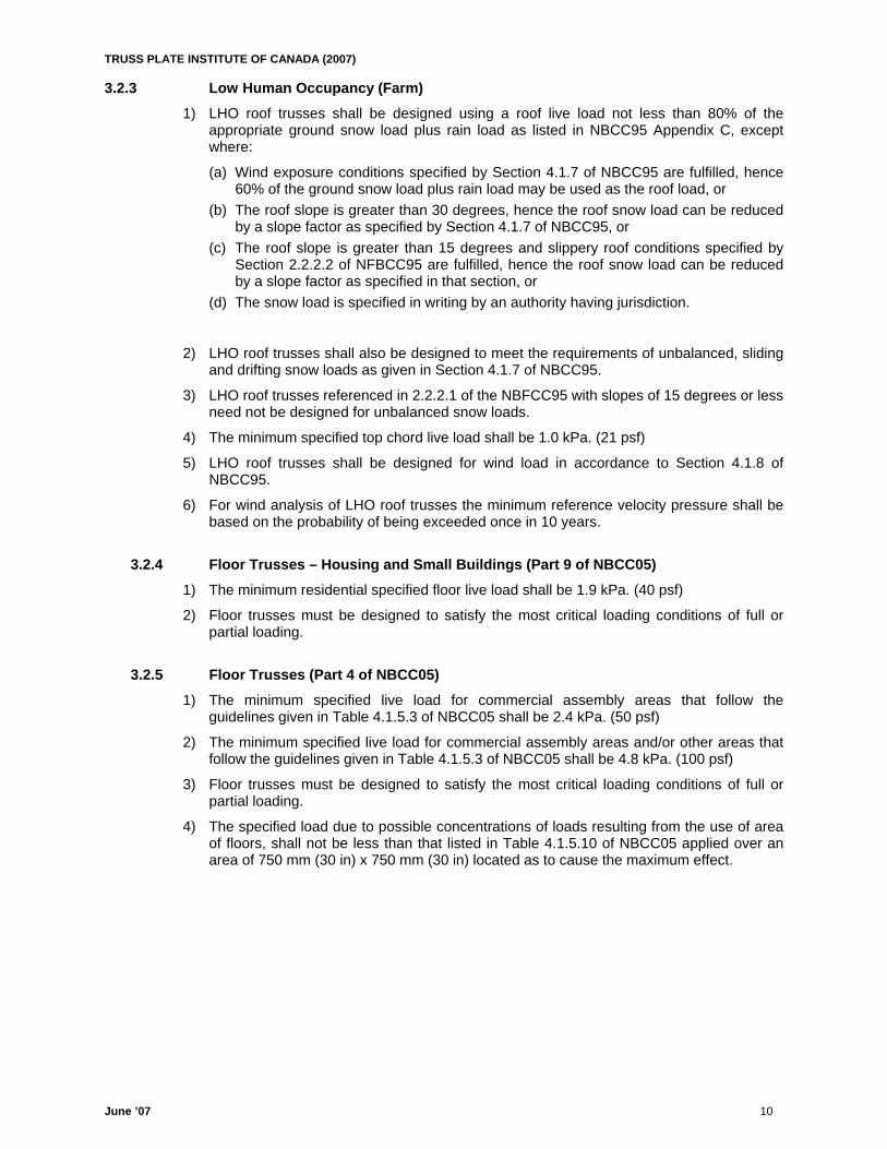
3.2.3 Low Human Occupancy (Farm) 1) LHO roof trusses shall be designed using a roof live load not less than 80% of the
appropriate ground snow load plus rain load as listed in NBCC95 Appendix C, except where:
(a) Wind exposure conditions specified by Section 4.1.7 of NBCC95 are fulfilled, hence 60% of the ground snow load plus rain load may be used as the roof load, or
(b) The roof slope is greater than 30 degrees, hence the roof snow load can be reduced by a slope factor as specified by Section 4.1.7 of NBCC95, or
(c) The roof slope is greater than 15 degrees and slippery roof conditions specified by Section 2.2.2.2 of NFBCC95 are fulfilled, hence the roof snow load can be reduced by a slope factor as specified in that section, or
(d) The snow load is specified in writing by an authority having jurisdiction.
2) LHO roof trusses shall also be designed to meet the requirements of unbalanced, sliding and drifting snow loads as given in Section 4.1.7 of NBCC95.
3) LHO roof trusses referenced in 2.2.2.1 of the NBFCC95 with slopes of 15 degrees or less need not be designed for unbalanced snow loads.
4) The minimum specified top chord live load shall be 1.0 kPa. (21 psf)
5) LHO roof trusses shall be designed for wind load in accordance to Section 4.1.8 of NBCC95.
6) For wind analysis of LHO roof trusses the minimum reference velocity pressure shall be based on the probability of being exceeded once in 10 years.
3.2.4 Floor Trusses – Housing and Small Buildings (Part 9 of NBCC05) 1) The minimum residential specified floor live load shall be 1.9 kPa. (40 psf)
2) Floor trusses must be designed to satisfy the most critical loading conditions of full or partial loading.
3.2.5 Floor Trusses (Part 4 of NBCC05) 1) The minimum specified live load for commercial assembly areas that follow the
guidelines given in Table 4.1.5.3 of NBCC05 shall be 2.4 kPa. (50 psf)
2) The minimum specified live load for commercial assembly areas and/or other areas that follow the guidelines given in Table 4.1.5.3 of NBCC05 shall be 4.8 kPa. (100 psf)
3) Floor trusses must be designed to satisfy the most critical loading conditions of full or partial loading.
4) The specified load due to possible concentrations of loads resulting from the use of area of floors, shall not be less than that listed in Table 4.1.5.10 of NBCC05 applied over an area of 750 mm (30 in) x 750 mm (30 in) located as to cause the maximum effect.
TRUSS PLATE INSTITUTE OF CANADA (2007)
June ’07 11
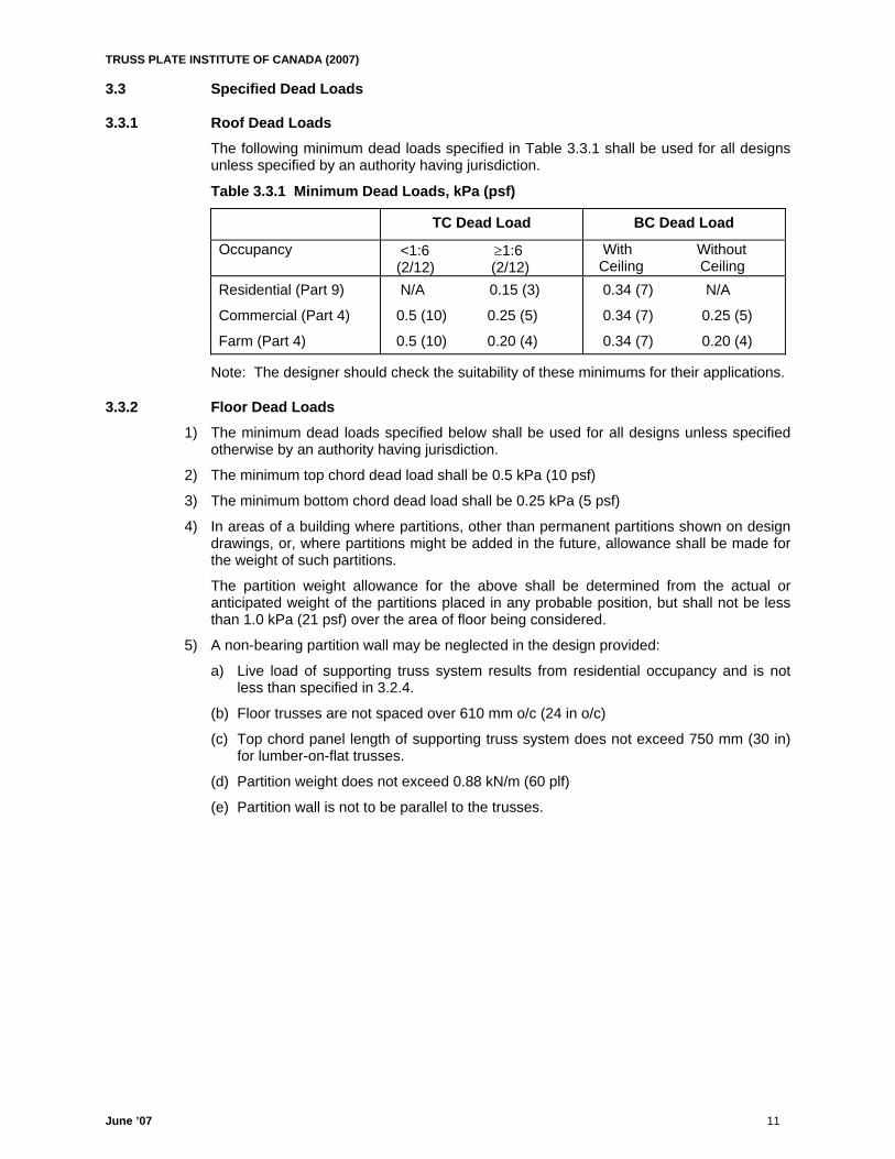
3.3 Specified Dead Loads 3.3.1 Roof Dead Loads The following minimum dead loads specified in Table 3.3.1 shall be used for all designs
unless specified by an authority having jurisdiction.
Table 3.3.1 Minimum Dead Loads, kPa (psf)
TC Dead Load BC Dead Load
Occupancy <1:6 ≥1:6 (2/12) (2/12)
With Without Ceiling Ceiling
Residential (Part 9)
Commercial (Part 4)
Farm (Part 4)
N/A 0.15 (3)
0.5 (10) 0.25 (5)
0.5 (10) 0.20 (4)
0.34 (7) N/A
0.34 (7) 0.25 (5)
0.34 (7) 0.20 (4)
Note: The designer should check the suitability of these minimums for their applications.
3.3.2 Floor Dead Loads 1) The minimum dead loads specified below shall be used for all designs unless specified
otherwise by an authority having jurisdiction.
2) The minimum top chord dead load shall be 0.5 kPa (10 psf)
3) The minimum bottom chord dead load shall be 0.25 kPa (5 psf)
4) In areas of a building where partitions, other than permanent partitions shown on design drawings, or, where partitions might be added in the future, allowance shall be made for the weight of such partitions.
The partition weight allowance for the above shall be determined from the actual or anticipated weight of the partitions placed in any probable position, but shall not be less than 1.0 kPa (21 psf) over the area of floor being considered.
5) A non-bearing partition wall may be neglected in the design provided:
a) Live load of supporting truss system results from residential occupancy and is not less than specified in 3.2.4.
(b) Floor trusses are not spaced over 610 mm o/c (24 in o/c)
(c) Top chord panel length of supporting truss system does not exceed 750 mm (30 in) for lumber-on-flat trusses.
(d) Partition weight does not exceed 0.88 kN/m (60 plf)
(e) Partition wall is not to be parallel to the trusses.
TRUSS PLATE INSTITUTE OF CANADA (2007)
June ’07 12
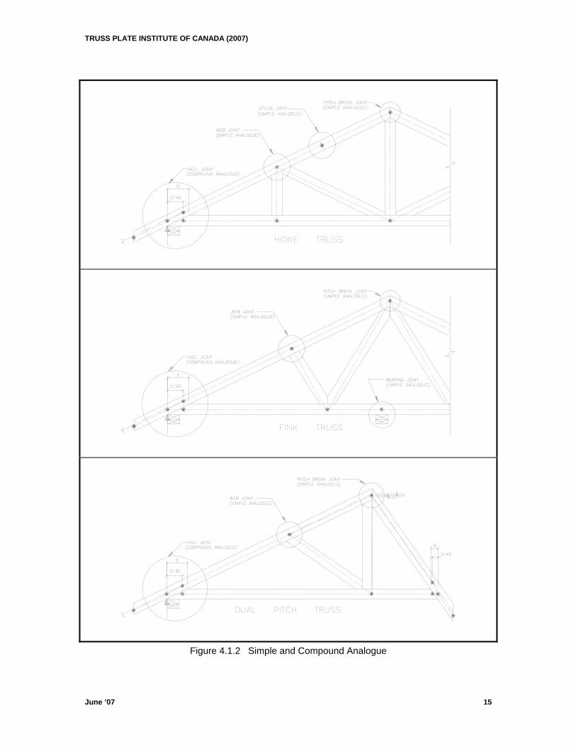
4. MEMBER DESIGN PROCEDURE 4.1 ANALOGUE 4.1.1 Analogue Joint Types (a) Pitch Break Joint: A joint formed by the intersection of two non-parallel chords (see
Fig 4.1.2). (b) Heel Joint: A pitch break joint consisting of a non-vertical top chord and non-vertical
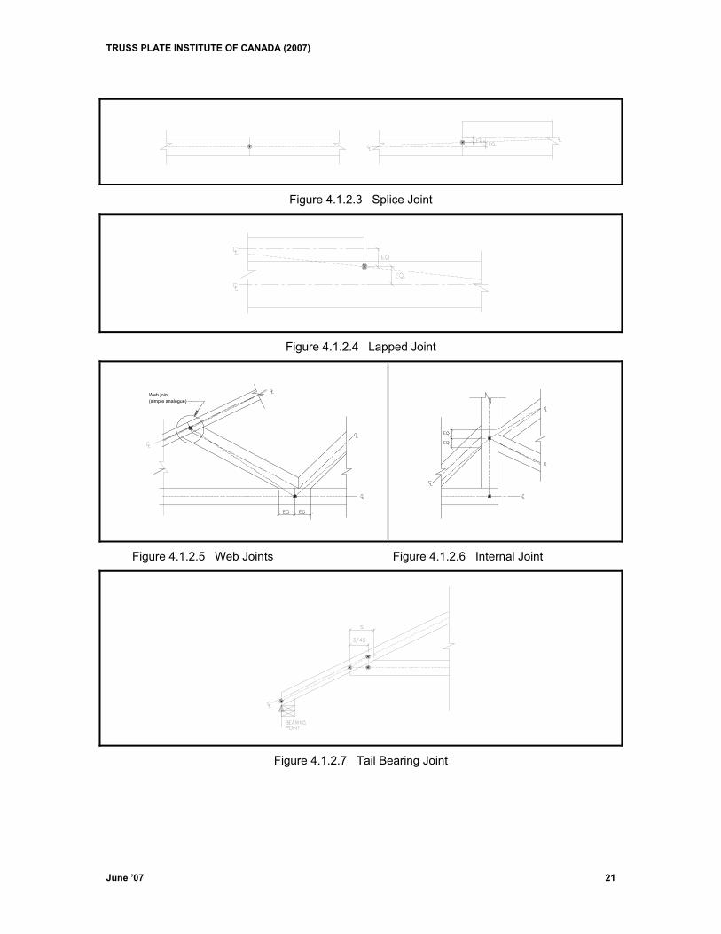
bottom chord (see Fig 4.1.2). (c) Splice Joint: A joint formed by two parallel and adjacent chords (see Fig 4.1.2.3). (d) Lapped Joint: A joint formed by one end of a chord placed parallel and in contact with
the adjacent chord along one of its edges (see Fig 4.1.2.4). (e) Web Joint: A joint formed by one or more webs along one edge of a given chord
(see Fig 4.1.2.5). (f) Internal Joint: A joint formed by two web joints on opposite edges of a given chord
such that their contact lengths overlap along the axis of the chord (see Fig 4.1.2.6). (g) Tail Bearing Joint: A joint consisting of a single member going to a support. (see Fig
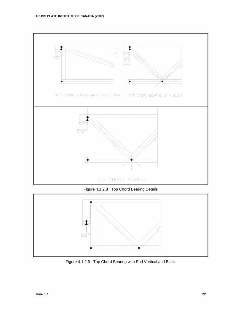
4.1.2.7) (h) Top Chord Bearing Joint: A joint consisting of two or more members connecting at
an exterior support. (see Fig 4.1.2.8) (i) Bearing Joint: A joint where a bearing touches a chord. (see Fig 4.1.2) 4.1.2 Analogue Points (a) Simple Analogue Point: An analogue point consisting of only one point formed by
two uniquely identifiable lines. (b) Compound Analogue Point: Analogue formed by two or more joints located at the
same physical joint. (see Fig 4.1.2) Except as in 4.1.3, analogue points shall be constructed as described in this section.
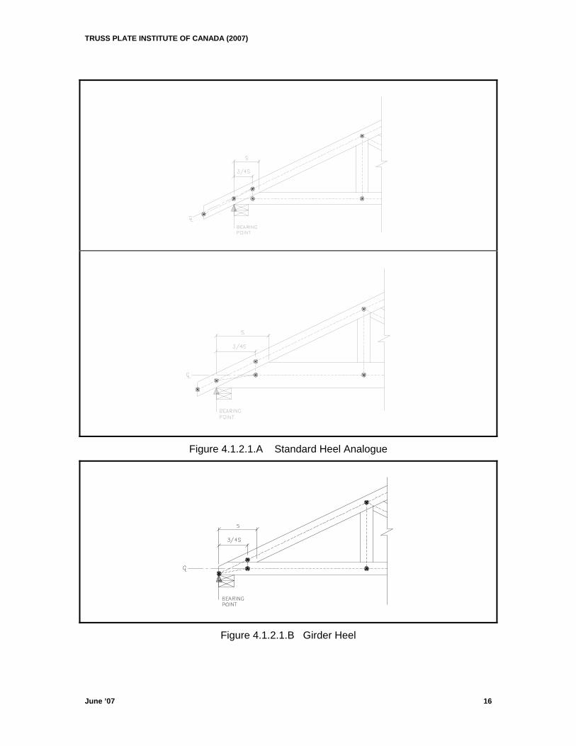
4.1.2.1 Heel Analogue: The heel analogue is a compound analogue consisting of three simple analogue points and three fictitious members. (see Fig 4.1.2.1.A-G)
a) First analogue point shall be determined as follows: Construct a vertical line at the end of TC or BC member whichever is shorter. (For Girder Heel, end of BC is always used to construct this line. See Fig 4.1.2.1.B. The only exception to this rule is in the case of a short cantilever. If the bearing occurs inside the point where the top chord terminates then this line is constructed at the end of the top chord and is considered the design span. See Appendix A.1 to A.4.) Find the intersection of the vertical line with the centrelines of the TC and BC. First heel analogue point shall be the lower of the two intersection points. This is the bearing point except as mentioned in (f) below.
b) The second heel analogue point shall be located at the intersection of the centreline of BC and a vertical at 75% of scarf length from the first analogue point. This vertical may not be more than 610mm (24”) away from the first analogue point.
c) The third heel analogue point shall be located along the centreline of the top chord directly above the second heel analogue point.
d) Where the second and the third points are closer to the first point than 2", remove the second and third points and reduce the heel analogue to simple analogue.
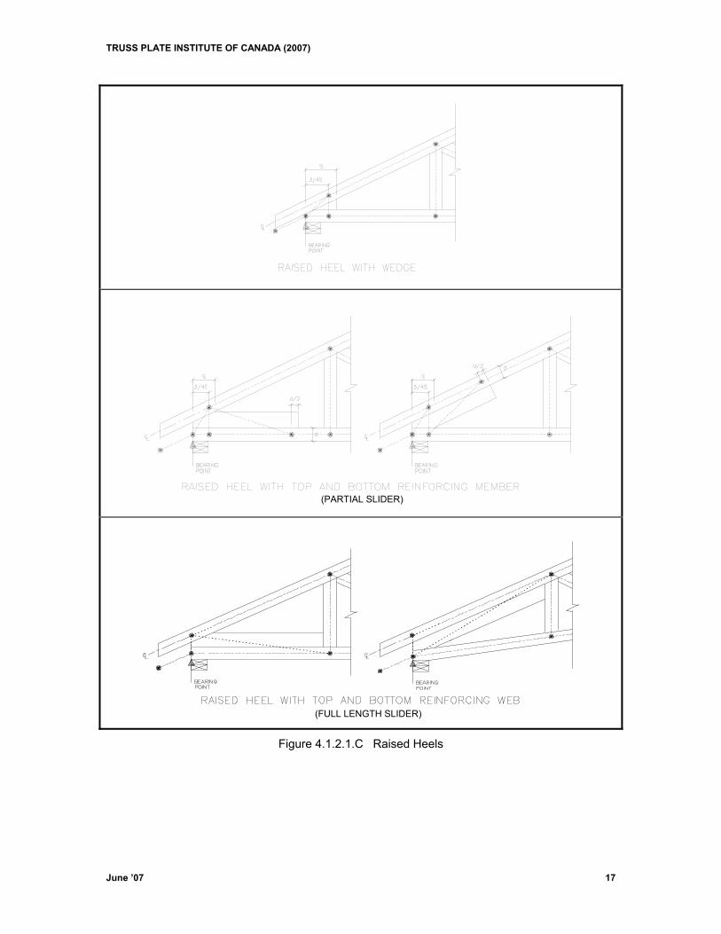
e) In the case of a reinforcing wedge, the second heel analogue point shall be located at the intersection of the centreline of the BC and, a vertical at 75% of the combined BC and wedge scarf lengths, from the first analogue point. This vertical may not be more than 610mm (24”) away from the first analogue point.
f) In the case of a reinforcing member, a fourth point is required. The reinforcing member acts as the fourth member. The fourth point is the intersection of the
TRUSS PLATE INSTITUTE OF CANADA (2007)
June ’07 13
centreline of the chord with a line perpendicular to the chord at a distance “d/2” where “d” is the depth of the chord. (see Fig 4.1.2.1.C & D)
g) In the case of a reinforcing web, the analogue is similar to the reinforcing member analogue with the following exceptions:
1. The fourth analogue point is the analogue point of the adjacent joint.
2. The fourth member is the reinforcing web.
3. The bearing point is the first analogue point only if any part of the bearing surface falls between the first and second analogue points inclusive. (see Fig 4.1.2.1.C & E) Short cantilever and high heel rules apply. (see Appendix “A”)
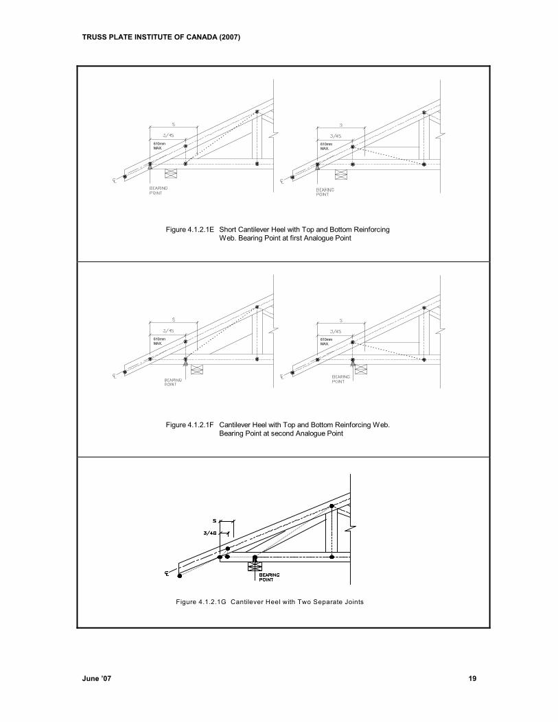
4. If any part of the bearing surface falls past the second analogue point, the bearing point is at the second analogue point or a new bearing joint is introduced depending on the contact between the bearing surface and the scarf of the reinforcing web. (see Fig 4.1.2.1F) Short cantilever and high heel rules do not apply for this condition.
5. If the reinforcing web is not fully parallel and touching the chord, two separate joints are constructed; a heel joint and a web joint. (see Fig 4.1.2.1G)
4.1.2.2 Pitch Break Analogue Point: The pitch break analogue point shall be located along a
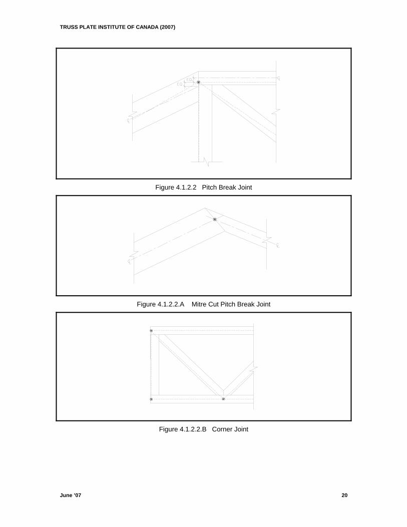
plumb line through the outside edge intersection of the two chords. The analogue point shall have the same X coordinate as the plumb location and Y coordinate equal to the average Y coordinates formed by intersection points of the chord centrelines and the plumb line. (see Fig 4.1.2.2)
In case of a mitre cut pitch break, the analogue point is the intersection of the centrelines of the chords. (see Fig 4.1.2.2.A) For corner joints, the analogue point shall be the intersection of the centreline of the chord and a line at the end of the chord. (see Fig 4.1.2.2.B)
4.1.2.3 Splice Joint Analogue Point: Analogue point shall be the point located at the halfway point between the intersection points of the centrelines of the two chord members and the splice line. (see Fig 4.1.2.3)
4.1.2.4 Lapped Joint Analogue Point: Analogue point shall be the point located at the halfway point between the intersection points formed by the end cut and centrelines of the chord members on the two sides of the joint. (see Fig 4.1.2.4)
4.1.2.5 Web Joint Analogue Point: Analogue point shall be the intersection of the centrelines of chord and a line perpendicular to the chord passing through the centre of contact area between the webs and the chord. (see Fig 4.1.2. and Fig 4.1.2.5)
4.1.2.6 Internal Joint Analogue Point: Analogue point shall be the intersection of the centreline of chord and a perpendicular through the centre of common contact area, from both sides, between the webs and the chord. (see Fig 4.1.2.6)
4.1.2.7 Tail Bearing Joint Analogue Point: Analogue point shall be at the intersection of the centreline of the chord and a vertical through outside corner of support. For a vertical tail bearing, use the horizontal through the outside corner of bearing instead of the vertical. (see Fig 4.1.2.7)
4.1.2.8 Top Chord Bearing Joint: Except as in 4.1.2.9 the top chord bearing joint analogue is compound and consists of two points. The first point is the bearing point and it is the intersection of the centreline of the top chord with a vertical along the inside face of the bearing. The second point is the intersection of the centreline of the top chord with a vertical through the outside edge of any webs coming to the top chord at the bearing. The maximum distance allowed between these points is 13mm (1/2”). (see Fig 4.1.2.8 and Appendix D)
TRUSS PLATE INSTITUTE OF CANADA (2007)
June ’07 14
4.1.2.9 Top Chord Bearing Joint With End Vertical and Block: The analogue of this point is compound and consists of three points and two ficitious members. The first joint is the bearing point and it is the intersection of a vertical through centreline of the required bearing size and surface of bearing. The second point is the intersection of a horizontal through the first point and the outside edge of end vertical. The third point is intersection of the centreline of the top chord and the outside edge of end vertical. (see Fig 4.1.2.9)
Top chord bearing joint guidelines in section 4.6.6 must be observed when using the analogue described in the above sections (4.1.2.8 and 4.1.2.9)
4.1.3 Analogue Modifications 4.1.3.1 Analogue points shall be constructed using the following heirarchy: Pitch break joints,
then, most member to least member web joints. All other joints not mentioned here may be constructed in any order.
4.1.3.2 Analogue points for joints connected by a vertical web to joints of higher hierarchy shall be obtained as intersection of vertical through the higher hierarchy joint and the centreline of chord.
4.1.3.3 Two analogue points closer to each other than 2" (unprojected) shall be reduced to one joint located between the two original joints.
TRUSS PLATE INSTITUTE OF CANADA (2007)
Figure 4.1.2 Simple and Compound Analogue
June ’07 15
TRUSS PLATE INSTITUTE OF CANADA (2007)
Figure 4.1.2.1.A Standard Heel Analogue
Figure 4.1.2.1.B Girder Heel
June ’07 16
TRUSS PLATE INSTITUTE OF CANADA (2007)
June ’07 17
Figure 4.1.2.1.C Raised Heels
(PARTIAL SLIDER)
(FULL LENGTH SLIDER)
TRUSS PLATE INSTITUTE OF CANADA (2007)
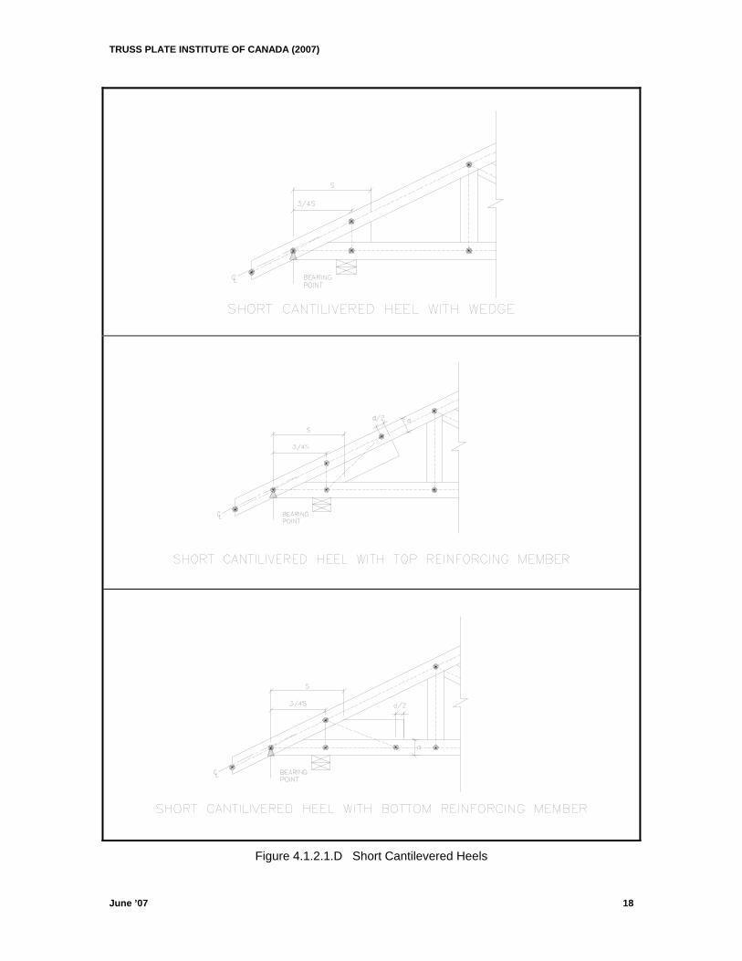
Figure 4.1.2.1.D Short Cantilevered Heels
June ’07 18
TRUSS PLATE INSTITUTE OF CANADA (2007)
June ’07 19
610mmMAX.
610mmMAX.
Figure 4.1.2.1E Short Cantilever Heel with Top and Bottom ReinforcingWeb. Bearing Point at first Analogue Point
610mmMAX.
610mmMAX.
Figure 4.1.2.1F Cantilever Heel with Top and Bottom Reinforcing Web.Bearing Point at second Analogue Point
Figure 4.1.2.1G Cantilever Heel with Two Separate Joints
TRUSS PLATE INSTITUTE OF CANADA (2007)
Figure 4.1.2.2 Pitch Break Joint
Figure 4.1.2.2.A Mitre Cut Pitch Break Joint
Figure 4.1.2.2.B Corner Joint
June ’07 20
TRUSS PLATE INSTITUTE OF CANADA (2007)
June ’07 21
Figure 4.1.2.3 Splice Joint
Figure 4.1.2.4 Lapped Joint
Web joint(simple analogue)
Figure 4.1.2.5 Web Joints Figure 4.1.2.6 Internal Joint
Figure 4.1.2.7 Tail Bearing Joint
TRUSS PLATE INSTITUTE OF CANADA (2007)
Figure 4.1.2.8 Top Chord Bearing Details
Figure 4.1.2.9 Top Chord Bearing with End Vertical and Block
June ’07 22
TRUSS PLATE INSTITUTE OF CANADA (2007)
June ’07 23
4.2 Ultimate Limit States 4.2.1 Method of Analysis Structural analysis shall be by stiffness or flexibility method utilizing pin-rigid
mathematical model.
1) Truss Model
(a) All chord members shall be rigidly connected through joints, including web joints and lapped joints. All splices shall be considered pinned unless designed for moment. Fictitious members representing top and bottom chords at the heel shall be pinned to each other but rigidly connected at other end.
(b) Ends of members connecting to pitch break joints shall be considered pinned at the joints.
(c) The fictitious vertical strut at heel shall be pinned to top and bottom chords. (d) Properties of fictitious members shall be as follows: A top chord fictitious member shall have the same properties as the adjacent top
chord. A bottom chord fictitious member shall have the same properties as the adjacent bottom chord. Other fictitious members shall have the properties of 2x4 No.2 S.P.F. lumber.
(e) Fictitious members in top chord bearing conditions such as in detail 4.1.2.9 shall be pinned at both ends and have properties of 2x4 No. 2 S.P.F. lumber.
(f) Overhangs shall be modelled such that they impose zero moment to the adjacent top chord member.
2) Support Model
Except for the leftmost support, all supports shall be considered as horizontal or vertical rollers. The leftmost support must be pinned. No support shall be considered to provide rotational restraint unless such restraint is adequately specified on the drawing. At a heel joint the support shall be located at the first analog point (the outermost joint). Except at heel joints, a support is considered to be at a joint when there is an overlap between contact surfaces of bearing and webs. A support is considered to be at the heel joint if the heel condition is to be used with short cantilever rules. See Section 4.6.3
3) Member Forces and Moments
(a) Member force shall be the average of the member end forces. Member force for connections shall be the actual member forces at the joint.
(b) Panel moment shall be taken as the maximum moment within the panel. Panel point moment shall be that at each individual panel end.
(c) Combined Stress index shall be calculated for the panel on the basis of CSI from average member force combined with the greater of maximum panel moment or the maximum panel point moment.
4.2.2 Ultimate Limit States Requirements
The design of truss members for ultimate limit states shall include: (a) Establishing the value of the effect of the factored loads individually and with the load
combinations specified in Section 3; and (b) Confirmation by rational means that for each load effect in item (a), the factored load
effect does not exceed the factored resistance as determined by appropriate clauses of this standard.
TRUSS PLATE INSTITUTE OF CANADA (2007)
June ’07 24
4.3 Specified Strengths 4.3.1 Visually Stress-Graded Lumber The specified strengths (MPa) for visually stress-graded structural joist and planks, light
framing, structural light framing and stud grade categories of lumber shall be those presented in Table 5.3.1.A and Table 5.3.1.B of 086-01.
4.3.2 Machine Stress-Rated And Machine Evaluated Lumber The specified strengths (MPa) for machine stress-rated lumber are given in Table 5.3.2
of 086-01. The specified strengths (MPa) for machine evaluated lumber are given in Table 5.3.3 of 086-01. The specified strengths in shear are not grade dependent and shall be taken from Table 5.3.1.A of 086-01 for the appropriate species.
4.3.3 Design Specified Strengths The design specified strengths are the product of the basic specified strengths and the
appropriate strength modification factors as in Section 4.3.4. 4.3.4 Modification Factors The strength modification factors are defined as follows:
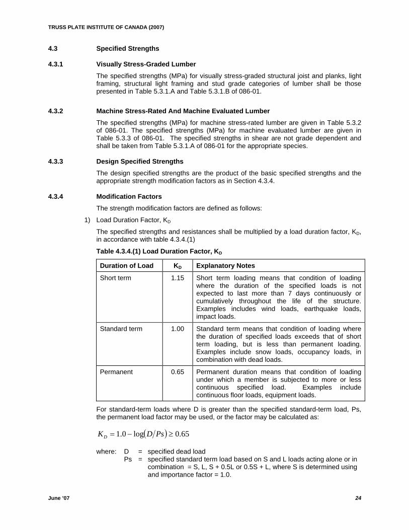
1) Load Duration Factor, KD
The specified strengths and resistances shall be multiplied by a load duration factor, KD, in accordance with table 4.3.4.(1)
Table 4.3.4.(1) Load Duration Factor, KD
Duration of Load KD Explanatory Notes
Short term 1.15 Short term loading means that condition of loading where the duration of the specified loads is not expected to last more than 7 days continuously or cumulatively throughout the life of the structure. Examples includes wind loads, earthquake loads, impact loads.
Standard term 1.00 Standard term means that condition of loading where the duration of specified loads exceeds that of short term loading, but is less than permanent loading. Examples include snow loads, occupancy loads, in combination with dead loads.
Permanent 0.65 Permanent duration means that condition of loading under which a member is subjected to more or less continuous specified load. Examples include continuous floor loads, equipment loads.
For standard-term loads where D is greater than the specified standard-term load, Ps, the permanent load factor may be used, or the factor may be calculated as:
( ) 65.0log0.1 ≥−= PsDKD where: D = specified dead load
Ps = specified standard term load based on S and L loads acting alone or in combination = S, L, S + 0.5L or 0.5S + L, where S is determined using and importance factor = 1.0.
TRUSS PLATE INSTITUTE OF CANADA (2007)
June ’07 25
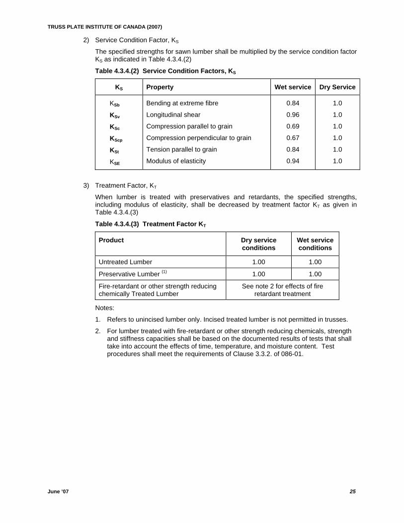
2) Service Condition Factor, KS
The specified strengths for sawn lumber shall be multiplied by the service condition factor KS as indicated in Table 4.3.4.(2)
Table 4.3.4.(2) Service Condition Factors, KS
KS Property Wet service Dry Service
KSb
KSv
KSc
KScp
KSt
KSE
Bending at extreme fibre
Longitudinal shear
Compression parallel to grain
Compression perpendicular to grain
Tension parallel to grain
Modulus of elasticity
0.84
0.96
0.69
0.67
0.84
0.94
1.0
1.0
1.0
1.0
1.0
1.0
3) Treatment Factor, KT
When lumber is treated with preservatives and retardants, the specified strengths, including modulus of elasticity, shall be decreased by treatment factor KT as given in Table 4.3.4.(3)
Table 4.3.4.(3) Treatment Factor KT
Product Dry service conditions
Wet service conditions
Untreated Lumber 1.00 1.00
Preservative Lumber (1) 1.00 1.00
Fire-retardant or other strength reducing chemically Treated Lumber
See note 2 for effects of fire retardant treatment
Notes:
1. Refers to unincised lumber only. Incised treated lumber is not permitted in trusses.
2. For lumber treated with fire-retardant or other strength reducing chemicals, strength and stiffness capacities shall be based on the documented results of tests that shall take into account the effects of time, temperature, and moisture content. Test procedures shall meet the requirements of Clause 3.3.2. of 086-01.
TRUSS PLATE INSTITUTE OF CANADA (2007)
June ’07 26
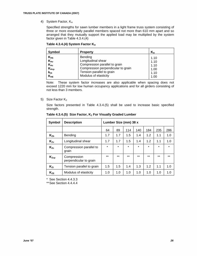
4) System Factor, KH
Specified strengths for sawn lumber members in a light frame truss system consisting of three or more essentially parallel members spaced not more than 610 mm apart and so arranged that they mutually support the applied load may be multiplied by the system factor given in Table 4.3.4.(4)
Table 4.3.4.(4) System Factor KH
Symbol Property KH
KHb KHv KHc KHcp kHt KHE
Bending Longitudinal shear Compression parallel to grain Compression perpendicular to grain Tension parallel to grain Modulus of elasticity
1.10 1.10 1.10 1.00 1.10 1.00
Note: These system factor increases are also applicable when spacing does not exceed 1220 mm for low human occupancy applications and for all girders consisting of not less than 3 members.
5) Size Factor KZ
Size factors presented in Table 4.3.4.(5) shall be used to increase basic specified strength.
Table 4.3.4.(5) Size Factor, KZ For Visually Graded Lumber
Symbol Description Lumber Size (mm) 38 x
64 89 114 140 184 235 286 KZb Bending 1.7 1.7 1.5 1.4 1.2 1.1 1.0
KZv Longitudinal shear 1.7 1.7 1.5 1.4 1.2 1.1 1.0
KZc Compression parallel to grain
* * * * * * *
KZcp Compression perpendicular to grain
** ** ** ** ** ** **
KZt Tension parallel to grain 1.5 1.5 1.4 1.3 1.2 1.1 1.0
KZE Modulus of elasticity 1.0 1.0 1.0 1.0 1.0 1.0 1.0
* See Section 4.4.3.3 ** See Section 4.4.4.4
TRUSS PLATE INSTITUTE OF CANADA (2007)
June ’07 27
4.4 Strength And Resistance 4.4.1 Bending Moment Resistance 1) The factored bending moment resistance, Mr of sawn members shall be taken as:
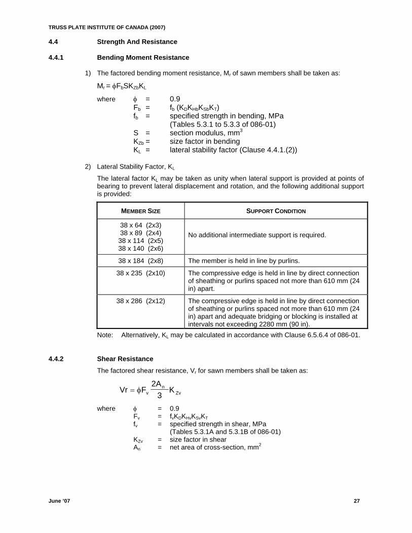
Mr = φFbSKZbKL where φ = 0.9 Fb = fb (KDKHbKSbKT) fb = specified strength in bending, MPa (Tables 5.3.1 to 5.3.3 of 086-01) S = section modulus, mm3 KZb = size factor in bending KL = lateral stability factor (Clause 4.4.1.(2)) 2) Lateral Stability Factor, KL
The lateral factor KL may be taken as unity when lateral support is provided at points of bearing to prevent lateral displacement and rotation, and the following additional support is provided:
MEMBER SIZE SUPPORT CONDITION
38 x 64 (2x3) 38 x 89 (2x4) 38 x 114 (2x5) 38 x 140 (2x6)
No additional intermediate support is required.
38 x 184 (2x8) The member is held in line by purlins.
38 x 235 (2x10) The compressive edge is held in line by direct connection of sheathing or purlins spaced not more than 610 mm (24 in) apart.
38 x 286 (2x12) The compressive edge is held in line by direct connection of sheathing or purlins spaced not more than 610 mm (24 in) apart and adequate bridging or blocking is installed at intervals not exceeding 2280 mm (90 in).
Note: Alternatively, KL may be calculated in accordance with Clause 6.5.6.4 of 086-01.
4.4.2 Shear Resistance The factored shear resistance, Vr for sawn members shall be taken as:
Vr F Kv Z= φ2A
3n
v
where φ = 0.9 Fv = fvKDKHvKSvKT fv = specified strength in shear, MPa (Tables 5.3.1A and 5.3.1B of 086-01) KZv = size factor in shear An = net area of cross-section, mm2
TRUSS PLATE INSTITUTE OF CANADA (2007)
June ’07 28
4.4.3 Compressive Resistance Parallel To Grain 1) Effective Length
Unless noted otherwise, the effective length Le = KeLp shall be used in determining the slenderness ratio of truss compression members.
where Ke = 0.8 for buckling between adjacent panel points in the truss Ke = 1.0 for buckling between brace or purlin locations on the truss Lp = actual length of member between adjacent analogue panel points, or;
locations of braces or purlins restraining buckling (normally perpendicular to the plane of the truss). For design of truss webs the longest cutting length shall be used.
Other recommended effective length factors Ke for compression members can be found in Appendix A.5.5.6.1 of 086-01.
2) Simple Compression Members - Constant Rectangular Cross-Section
The slenderness ratio Cc of simple compression members of constant rectangular section must not exceed 50 and shall be taken as the greater of:
Cc =effective length associatied with width
member width
Cc =effective length associatied with depth
member depth
Note: The slenderness ratio Cc of a simple tension member shall be limited to 80. Ke for a tension member should be taken as 1.0.
3) Factored Compressive Resistance Parallel To Grain
The factored compressive resistance parallel to grain, Pr shall be taken as:
P F AK Kr C Zc= φ C
where φ = 0.8 FC = fc(KDKHcKScKT) fc = specified strength in compression parallel to grain, MPa (Tables 5.3.1 to 5.3.3 of 086-01) KZc = 6.3(dL)-0.13 ≤ 1.3
where d = dimension in direction of buckling (depth or width), mm L = length associated with member dimension, mm
Note: The member length L used to compute the factor KZC shall be the greater of the panel length or one-half the chord length between pitch breaks for chord design; and, shall be the longest cutting length or the analogue length for web design.
4) Slenderness Factor, KC
The slenderness factor, KC, shall be determined from:
KC = +⎧⎨⎪
⎩⎪
⎫⎬⎪
⎭⎪
−
1.0 F K C35E K K
c Zc C3
05 SE T
1
where E05 = 0.82E for MSR lumber = 0.75E for MEL lumber = as specified in Tables 5.3.1A and 5.3.1B of 086-01, for visually graded
lumber
TRUSS PLATE INSTITUTE OF CANADA (2007)
June ’07 29
cp
4.4.4 Compressive Resistance Perpendicular To Grain (Bearing Resistance) 1) Effect Of All Applied Loads
The factored compressive resistance perpendicular to grain under the effect of all factored loads shall be taken as Qr in the following formula:
Q F A K Kr cp b B Z= φ
where φ = 0.8 Fcp = fcp(KDKScpKT) fcp = specified strength in compression perpendicular to grain, MPa
(Tables 5.3.1 to 5.3.3 of 086-01) Ab = bearing area, mm2
KB = length of bearing factor, Clause 4.4.4.5 K
B
Zcp = size factor for bearing, Clause 4.4.4.4
Note: The requirements of 4.4.4.(1) may be met by providing adequate bearing reinforcement against the effects of concentrated bearing loads acting near a support. See Section 5.5.9
2) Effects Of Loads Applied Near A Support
The factored compressive resistance perpendicular to grain, under the effect of only those loads applied within a distance from the centre of the support equal to the depth of the member, shall be taken as Q'r in the following formula:
Q'r = (2/3) φ FcpA'bKBKB Zcp
where = 0.8 F
φcp = fcp(KDKScpKT)
A'b = average bearing area (Clause 4.4.4.(3))
3) Unequal Bearing Areas On Opposite Surfaces Of A Member
Where unequal bearing areas are used on opposite surfaces of a member, the average bearing area shall not exceed the following:
A'b = b L L but b Lb bb
1 212
15+⎧⎨⎩
⎫⎬⎭
≤, . ( )
where Lb1 = lesser bearing length, mm Lb2 = larger bearing width, mm b = average bearing width (perpendicular to grain), mm
4) Size Factor For Bearing, KZcp
For lumber used on flat, as opposed to on edge, the compression perpendicular to grain may be multiplied by a size factor for bearing, KZcp in accordance with Table 4.4.4.(4)
TRUSS PLATE INSTITUTE OF CANADA (2007)
June ’07 30
Table 4.4.4.(4) Size Factor For Bearing, KZcp
Ratio of Member Width To Member Depth* KZCP
1.0 or Less 1.00
2.0 or More 1.15
* Interpolation applies to intermediate ratios.
5) Length Of Bearing Factor, KBB
When lengths of bearing are less than 150 mm, specified strengths in compression perpendicular to grain may be multiplied by a length of bearing factor in accordance with Table 4.4.4.(5) provided that: (a) no part of the bearing area is less than 75 mm from the end of the members; and (b) bearing areas do not occur in positions of high bending stresses.
Table 4.4.4.(5) Length Of Bearing Factor, KB
Bearing Length Measured Parallel To Grain (mm) Modification Factor, KB
12.5 and Less 1.75 25.0 1.38 38.0 1.25 50.0 1.19 75.0 1.13
100.0 1.10 150.0 or More 1.00
4.4.5 Tensile Resistance Parallel To Grain The factored tensile resistance, Tr, parallel to grain shall be taken as:
Tr = φFtAnKZt
where φ = 0.9 Ft = ft(KDKHtKStKT) ft = specified strength parallel to grain, MPa
(Tables 5.3.1 to 5.3.3 of 086-01) An = net area of cross-section, mm2
KZt = size factor in tension
4.4.6 Stress Index due to Bending Members subject to factored bending moment, Mf, shall be so proportioned that:
MM
f
r≤ 1.0
4.4.7 Stress Index due to Shear Members subject to factored shear load, Vf, shall be so proportioned that:
VV
f
r≤ 1.0
TRUSS PLATE INSTITUTE OF CANADA (2007)
June ’07 31
4.4.8 Stress Index due to Compression (Parallel to Grain) Members subject to factored compressive axial load, Pf, shall be so proportioned that;
PP
f
r≤ 1.0
4.4.9 Stress Index due to Compression (Perpendicular to Grain) Members subject to factored compressive bearing load, Qf , shall be so proportioned
that;
f
r≤ 1.0
4.4.10 Stress Index due to Tension Members subject to factored tensile axial load, Tf, shall be so proportioned that:
TT
f
r≤ 10.
4.4.11 Combined Stress Index due to Tension and Bending Members subject to both bending and axial tension shall be so proportioned that:
TT
MM
f
r
f
r+ ≤ 1.0
4.4.12 Combined Stress Index due to Compression and Bending Except as permitted in Section 4.4.13, members subject to both bending and axial
compression shall be so proportioned that;
PP
MM
f
r
f
r+ ≤ 1.0
4.4.13 Combined Stress Index due to Compression and Bending (Modified formula as per Section 5.5.13.5 086-01)
Provided; (a) the members form part of a fully triangulated, metal plate connected truss; and; (b) the spacing of the truss does not exceed 610 mm (24 in) or the truss does not
support more than 610 mm (24 in) of uniform loading; and; (c) clear spans between bearings does not exceed 12.20 m (40 ft) and, the design span
or overall length of the truss, not including overhangs, does not exceed 18.3 m (60 ft), and;
(d) the top chord slope is not less than 1/6, which is meant to exclude flat roof trusses but not flat top trusses forming part of hip roof systems;
Note: This clause is not for use with girder, bow string, semi-circular, attic, flat roof ,or floor trusses.
Members subject to both bending and axial compression shall be so proportioned that;
PP
MK M
f
r
f
M r
⎧⎨⎩
⎫⎬⎭
+ ≤2
1.0
TRUSS PLATE INSTITUTE OF CANADA (2007)
June ’07 32
1) Bending Capacity Modification Factor, KM
The bending capacity modification factor, KM, shall be determined as shown in the following: (a) Compression chord members continuous over one or more panel points, and where;
1.0 < MM
1
2≤ 3.0
KM = 131 012 1
2
1 6
. ./
+⎧⎨⎩
⎫⎬⎭
⎡
⎣⎢⎢
⎤
⎦⎥⎥
⎧⎨⎩
⎫⎬⎭
≤−
MM
Ldp 1.3
(b) Compression chord members continuous over one or more panel points, and where;
-1.0 ≤MM
1
2 ≤ 1.0
KM = 2 20 0 53 0 64 0 411
2
1
2
21
2
3 1 6
. . . ./
−⎧⎨⎩
⎫⎬⎭−
⎧⎨⎩
⎫⎬⎭
+⎧⎨⎩
⎫⎬⎭
⎡
⎣
⎢⎢
⎤
⎦
⎥⎥
⎧⎨⎩
⎫⎬⎭
≤−
MM
MM
MM
Ldp 1.3
(c) All other compression chord members
KM = 1.67 Ldp⎧
⎨⎩
⎫⎬⎭
≤−1 6
13/
.
where Lp = actual length of the member between adjacent analogue panel points,mm
d = depth of the member between adjacent analogue panel points, mm *M1 = maximum bending moment between analogue panel points, N-mm M2 = maximum of the two panel point bending moments, N-mm
Note: The sign of the bending moment, M1 and M2 are retained in determining KM. The factored bending moment, Mf, used in Section 4.4.13 is the larger of the absolute value of M1 and M2.
* Maximum of bending moment at points along a panel where the slope of the moment curve changes sign. Where there are no such points along the panel, M1 shall take the value of the bending moment at mid panel.
TTRRUUSSSS PPLLAATTEE IINNSSTTIITTUUTTEE OOFF CCAANNAADDAA ((22000077))
JJuunnee ’’0077 3333
4.5 Serviceability Limit States Design for serviceability Limit States shall include:
(a) establishing the value of the effect of the specified loads individually and with the load combinations specified in Section 3; and
(b) confirming by rational means that for each load effect in item (a), the structural effect falls within the limits specified in appropriate clauses contained herein.
4.5.1 Serviceability Requirements (Allowable Deflections) 1) Modulus of Elasticity
The modulus of elasticity for stiffness calculations, ES, shall be taken as:
ES = E(KSEKT)
where
E = specified modulus of elasticity KSE = service condition factor KT = treatment factor 2) Joint and member deflections shall be determined using the methods presented in
Section 4.2.1. Loadings used are as described in Section 3.0. 3) Maximum vertical truss deflection shall be the largest of deflections calculated at any
panel point, or within any bottom chord panel. Top chord members shall be checked for their vertical panel deflections relative to their end points.
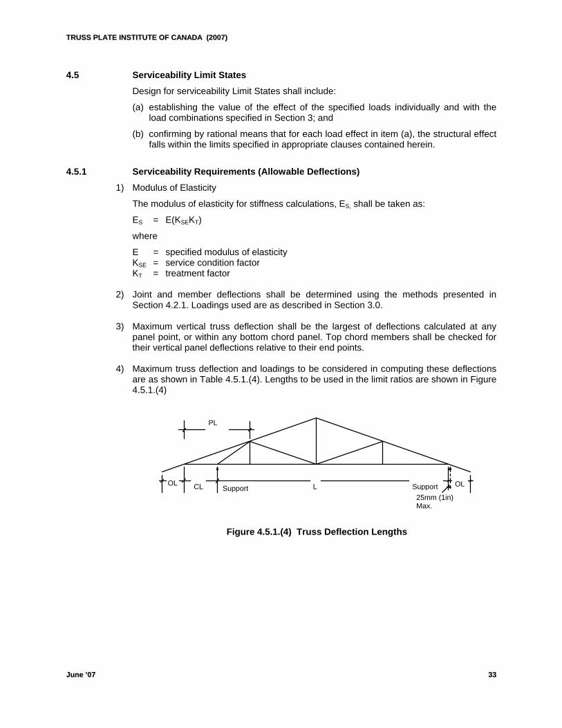
4) Maximum truss deflection and loadings to be considered in computing these deflections
are as shown in Table 4.5.1.(4). Lengths to be used in the limit ratios are shown in Figure 4.5.1.(4)
Figure 4.5.1.(4) Truss Deflection Lengths
PL
OLSupport 25mm (1in) Max.
CL LOL Support
TTRRUUSSSS PPLLAATTEE IINNSSTTIITTUUTTEE OOFF CCAANNAADDAA ((22000077))
JJuunnee ’’0077 3344
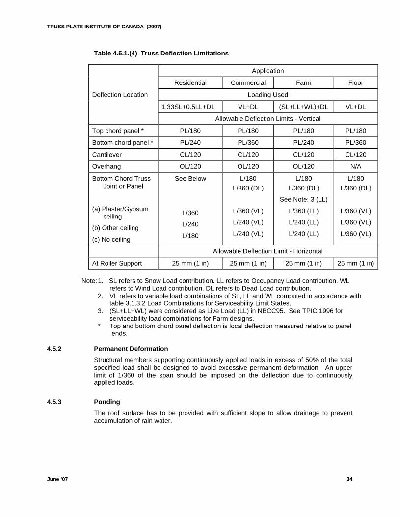
Table 4.5.1.(4) Truss Deflection Limitations
Application
Residential Commercial Farm Floor
Deflection Location Loading Used
1.33SL+0.5LL+DL VL+DL (SL+LL+WL)+DL VL+DL
Allowable Deflection Limits - Vertical
Top chord panel * PL/180 PL/180 PL/180 PL/180
Bottom chord panel * PL/240 PL/360 PL/240 PL/360
Cantilever CL/120 CL/120 CL/120 CL/120
Overhang OL/120 OL/120 OL/120 N/A
Bottom Chord Truss Joint or Panel
(a) Plaster/Gypsum ceiling
(b) Other ceiling
(c) No ceiling
See Below
L/360
L/240
L/180
L/180 L/360 (DL)
L/360 (VL)
L/240 (VL)
L/240 (VL)
L/180 L/360 (DL)
See Note: 3 (LL)
L/360 (LL)
L/240 (LL)
L/240 (LL)
L/180 L/360 (DL)
L/360 (VL)
L/360 (VL)
L/360 (VL)
Allowable Deflection Limit - Horizontal
At Roller Support 25 mm (1 in) 25 mm (1 in) 25 mm (1 in) 25 mm (1 in) Note: 1. SL refers to Snow Load contribution. LL refers to Occupancy Load contribution. WL
refers to Wind Load contribution. DL refers to Dead Load contribution. 2. VL refers to variable load combinations of SL, LL and WL computed in accordance with
table 3.1.3.2 Load Combinations for Serviceability Limit States. 3. (SL+LL+WL) were considered as Live Load (LL) in NBCC95. See TPIC 1996 for
serviceability load combinations for Farm designs. * Top and bottom chord panel deflection is local deflection measured relative to panel
ends. 4.5.2 Permanent Deformation Structural members supporting continuously applied loads in excess of 50% of the total
specified load shall be designed to avoid excessive permanent deformation. An upper limit of 1/360 of the span should be imposed on the deflection due to continuously applied loads.
4.5.3 Ponding The roof surface has to be provided with sufficient slope to allow drainage to prevent
accumulation of rain water.
TTRRUUSSSS PPLLAATTEE IINNSSTTIITTUUTTEE OOFF CCAANNAADDAA ((22000077))
JJuunnee ’’0077 3355
4.6 Special Design Considerations 4.6.1 Overhangs Top chord overhangs for all categories of trusses shall be treated as simple overhangs,
with no consideration of any support provided by the soffit return, except in cases where the truss designer is able to ensure that such consideration is provided for in the design and construction of the building.
4.6.2 Splices Splice locations as permitted in section 4.6.2.(1) and 4.6.2.(2) with tolerances described
in 4.6.2.(3) are only intended for use in trusses where these locations are of low chord moment. i.e. Chords of triangulated, uniformly loaded, statically determinate trusses. For other cases where the splice is positioned at a location of substantial chord moment, it must either be designed for in the connection, or, eliminated by describing the splice as a pin joint in the analysis.
1) Top Chord Splices
(a) shall not be located at any joint and shall not be located in the panel adjacent to heel joint.
(b) shall not be located at the quarter point adjacent to any perimeter break. (c) may be located at either quarter point of interior panels except there shall be no more
than one splice per panel.
2) Bottom Chord Splices
(a) shall not be located in the panel adjacent to heel joint and shall not be located at the quarter point adjacent to any perimeter break.
(b) may be located between quarter points of interior panels. (c) may be located at any interior joint except that the joint adjacent to heel joint may not
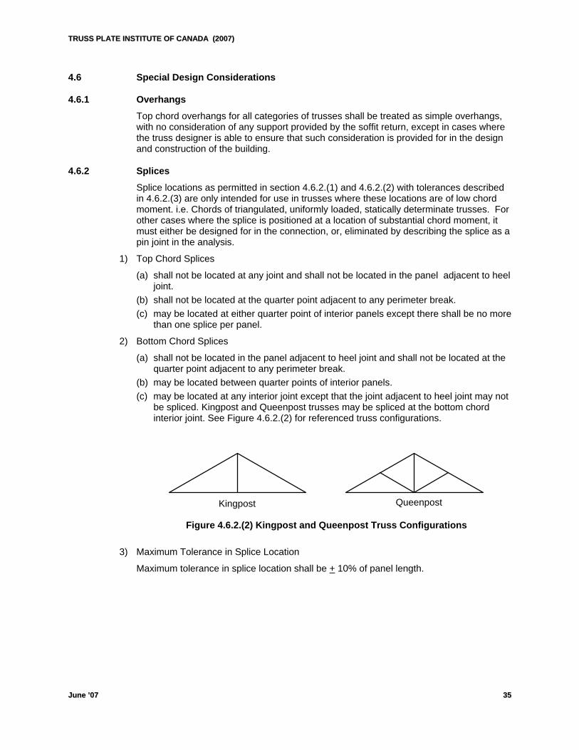
be spliced. Kingpost and Queenpost trusses may be spliced at the bottom chord interior joint. See Figure 4.6.2.(2) for referenced truss configurations.
Queenpost Kingpost Figure 4.6.2.(2) Kingpost and Queenpost Truss Configurations 3) Maximum Tolerance in Splice Location
Maximum tolerance in splice location shall be + 10% of panel length.
TTRRUUSSSS PPLLAATTEE IINNSSTTIITTUUTTEE OOFF CCAANNAADDAA ((22000077))
JJuunnee ’’0077 3366
4.6.3 Short Cantilevers and Heel Cuts Short cantilevers and high heel cuts shall be designed in accordance to procedures
presented in Appendix A. 4.6.4 Girder Trusses (Single and Multi-Ply) 1) Girder type heels are created by cutting the top chord onto a scarfed bottom chord. In
this scarfing, the resulting section of bottom chord directly over the inside face of the bearing shall not be less than the greater of 50% of the original bottom chord section or 100 mm (4”). Girder type heel design procedures are presented in Appendix F.
2) Truss-to-truss connection of multi-ply girder trusses carrying load that is not evenly distributed to each ply shall be performed in accordance to Table B.1 to B.5, Appendix B. Girders carrying this type of loading shall be limited to 5 plies maximum.
3) Truss-to-truss connection of multi-ply girder trusses, carrying load that is evenly distributed to all plies, shall be performed using the minimum number of rows shown in Table B.1., Appendix B and a spacing of 300 mm (12 in). Girders carrying this type of loading shall be limited to 10 plies.
4.6.5 Truss Bracing
1) For instructions on installation of temporary and permanent truss bracing, refer to TPIC Brochure “Handling, Erection and Bracing of Wood Trusses”.
Truss bracing location, as required in the design of the truss component, shall be specified by the truss designer/engineer.
2) For HSB trusses, minimum fastening of braces shall be as per NBCC05, Section 9.23.13.11
19 x 89 (1x4) braces 2 - 63 mm (2-1/2”) common wire nails 38 x 89 (2x4) braces 2 - 76 mm (3”) common wire nails. 3) An alternate method for bracing compression webs and long tension webs is by applying
a member parallel to the web to form a T-section. See Table C.1.1, Appendix C.
4.6.6 Top Chord Bearing Guidelines
1) For lumber-on-edge top chord bearing trusses the recommended maximum factored reactions for Spruce-Pine-Fir and D.Fir chords are as shown in Table D.4.6.6.1, Appendix D for the various truss configurations. The recommended maximum gaps and minimum chord coverage must be observed when using these values.
Reaction limits are based on gross reaction and load duration factor for standard term loading. Values shall be adjusted downward for permanent loading and upward for short term loading using appropriate duration of load factors for plating.
2) For lumber-on-flat top chord bearing trusses, the recommended maximum factored reactions for Spruce-Pine-Fir and D.Fir chords are as shown in Table D.4.6.6.2 Appendix D for the various truss configurations. The recommended maximum gaps and minimum chord bites also shown must be observed when using these values.
Reaction limits are based on gross reaction and load duration factor for standard term loading. Values shall be adjusted downward for permanent loading and upward for short term loading using appropriate duration of load factors for plating.
TTRRUUSSSS PPLLAATTEE IINNSSTTIITTUUTTEE OOFF CCAANNAADDAA ((22000077))
JJuunnee ’’0077 3377
5. JOINT DESIGN PROCEDURES 5.1 General The design requirements for truss plate joints, utilizing light gauge metal plates, shall be
in accordance with 086-01 Section 10. 1) These procedures do not apply to the following conditions:
(a) corrosive conditions (b) galvanized truss plates used in lumber that has been treated with fire retardant and is
used in wet service conditions or in locations prone to condensation NOTE: For metal connector plates used in environmental conditions that fall within the scope of
(a) & (b) above, refer to Appendix E.
2) Design criteria for truss plates are based on the following conditions:
(a) the plate is prevented from deforming during installation; (b) the teeth are normal to the surface of the lumber; (c) the tooth penetration in joints is not less than that used in the tests to determine the
resistance values; and (d) the lumber beneath the plate does not contain wane, loose knots, or knot holes
3) Thickness of members used in joints shall not be less than twice the tooth penetration. 4) Joint design shall be based on tight fitted joints with truss plates placed on opposing
faces in such a way that, at each joint, the plates on opposing faces are identical and are placed directly opposite each other.
5) The lateral resistance value used to determine necessary plate area for any member
shall be the appropriate value considering direction of load relative to grain and direction of load relative to primary axis of plate (see fig. 5.1.(5)). The resistance value is determined using the test values in conjunction with the formulae contained in Clause 5.3.3.
6) The unit values of lateral resistance of teeth shall be expressed as per tooth, per rosette,
or per net area, whichever is appropriate or preferred. The design shall be based on net area method using test values or on gross area method using 80 percent of the test values and with areas defined in items (a) and (b) as follows:
(a) the gross area is defined as the total area of member covered by a truss plate: (b) the net area is defined as the total area of a member covered by a truss plate less
the area within a given distance from the edge or end of member. For net area calculation, the minimum end distance measured parallel to grain, shall be the greater of 12 mm (1/2”), or 1/2 the length of tooth; the minimum edge distance measured perpendicular to grain, shall be the greater of 6 mm (1/4”), or 1/4 the length of the tooth.
Any joint in a truss may be designed by either net or gross area method of joint design but not a combination of both within same joint.
7) Minimum Bite for Chords and Webs
At all joints, the connector plates are to be sized such that the minimum bites into all chords and webs are as given in Table 5.1.(7):
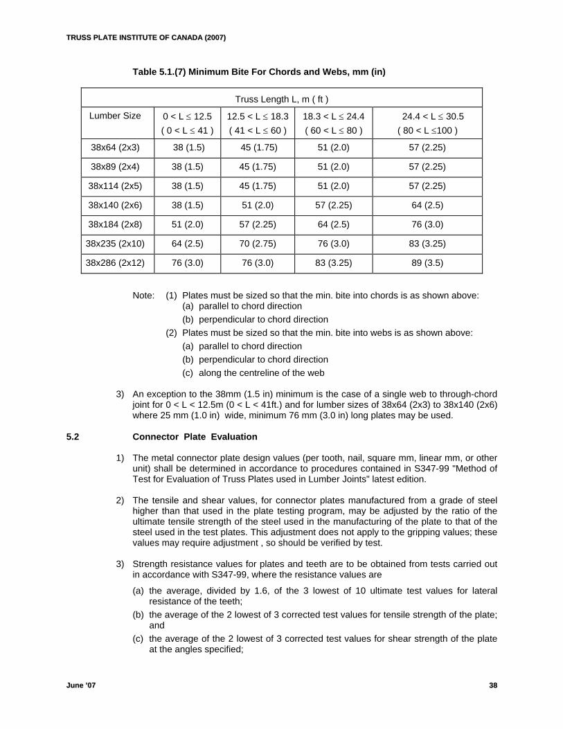
TTRRUUSSSS PPLLAATTEE IINNSSTTIITTUUTTEE OOFF CCAANNAADDAA ((22000077))
JJuunnee ’’0077 3388
Table 5.1.(7) Minimum Bite For Chords and Webs, mm (in)
Truss Length L, m ( ft )
Lumber Size 0 < L ≤ 12.5 ( 0 < L ≤ 41 )
12.5 < L ≤ 18.3 ( 41 < L ≤ 60 )
18.3 < L ≤ 24.4 ( 60 < L ≤ 80 )
24.4 < L ≤ 30.5 ( 80 < L ≤100 )
38x64 (2x3) 38 (1.5) 45 (1.75) 51 (2.0) 57 (2.25)
38x89 (2x4) 38 (1.5) 45 (1.75) 51 (2.0) 57 (2.25)
38x114 (2x5) 38 (1.5) 45 (1.75) 51 (2.0) 57 (2.25)
38x140 (2x6) 38 (1.5) 51 (2.0) 57 (2.25) 64 (2.5)
38x184 (2x8) 51 (2.0) 57 (2.25) 64 (2.5) 76 (3.0)
38x235 (2x10) 64 (2.5) 70 (2.75) 76 (3.0) 83 (3.25)
38x286 (2x12) 76 (3.0) 76 (3.0) 83 (3.25) 89 (3.5)
Note: (1) Plates must be sized so that the min. bite into chords is as shown above:
(a) parallel to chord direction (b) perpendicular to chord direction
(2) Plates must be sized so that the min. bite into webs is as shown above: (a) parallel to chord direction (b) perpendicular to chord direction (c) along the centreline of the web
3) An exception to the 38mm (1.5 in) minimum is the case of a single web to through-chord
joint for 0 < L < 12.5m (0 < L < 41ft.) and for lumber sizes of 38x64 (2x3) to 38x140 (2x6) where 25 mm (1.0 in) wide, minimum 76 mm (3.0 in) long plates may be used.
5.2 Connector Plate Evaluation 1) The metal connector plate design values (per tooth, nail, square mm, linear mm, or other
unit) shall be determined in accordance to procedures contained in S347-99 "Method of Test for Evaluation of Truss Plates used in Lumber Joints" latest edition.
2) The tensile and shear values, for connector plates manufactured from a grade of steel
higher than that used in the plate testing program, may be adjusted by the ratio of the ultimate tensile strength of the steel used in the manufacturing of the plate to that of the steel used in the test plates. This adjustment does not apply to the gripping values; these values may require adjustment , so should be verified by test.
3) Strength resistance values for plates and teeth are to be obtained from tests carried out
in accordance with S347-99, where the resistance values are
(a) the average, divided by 1.6, of the 3 lowest of 10 ultimate test values for lateral resistance of the teeth;
(b) the average of the 2 lowest of 3 corrected test values for tensile strength of the plate; and
(c) the average of the 2 lowest of 3 corrected test values for shear strength of the plate at the angles specified;
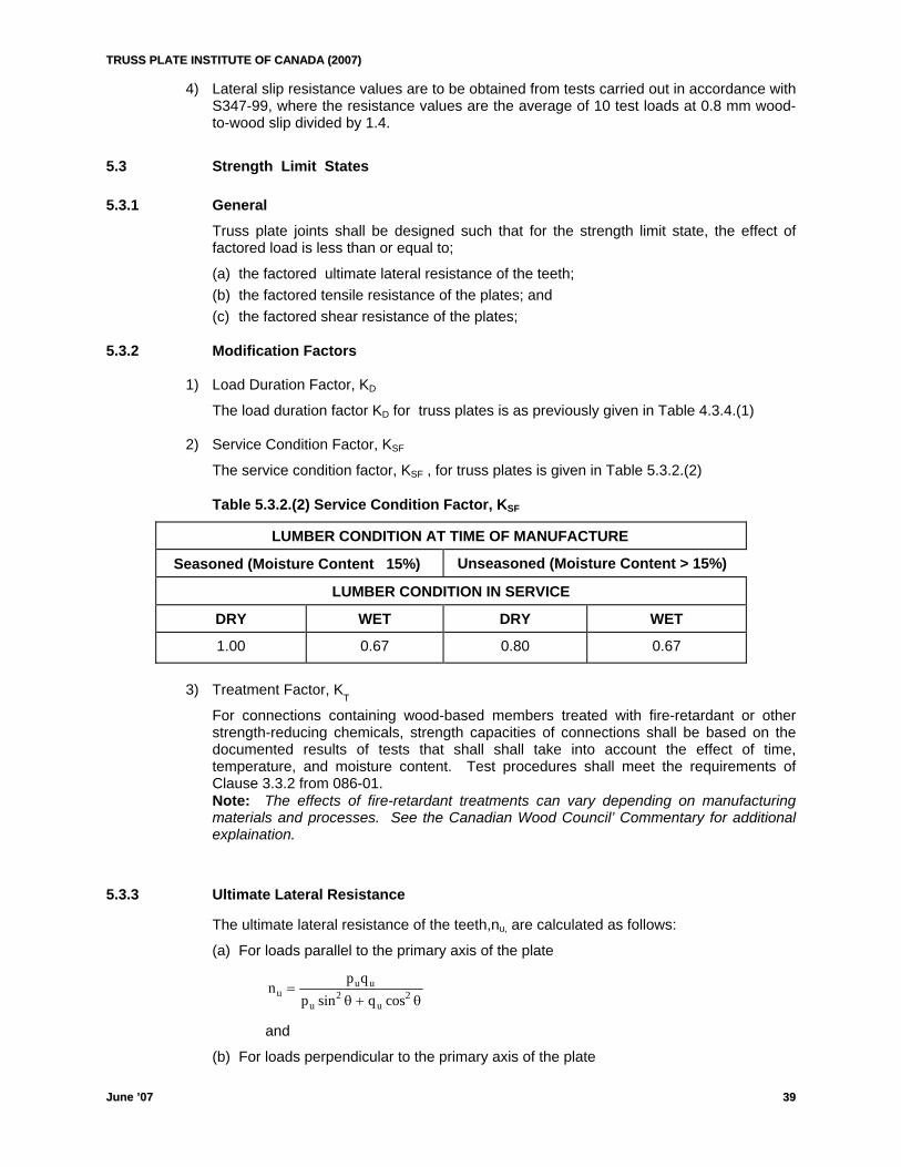
TTRRUUSSSS PPLLAATTEE IINNSSTTIITTUUTTEE OOFF CCAANNAADDAA ((22000077))
JJuunnee ’’0077 3399
4) Lateral slip resistance values are to be obtained from tests carried out in accordance with S347-99, where the resistance values are the average of 10 test loads at 0.8 mm wood-to-wood slip divided by 1.4.
5.3 Strength Limit States 5.3.1 General Truss plate joints shall be designed such that for the strength limit state, the effect of
factored load is less than or equal to;
(a) the factored ultimate lateral resistance of the teeth; (b) the factored tensile resistance of the plates; and (c) the factored shear resistance of the plates;
5.3.2 Modification Factors 1) Load Duration Factor, KD
The load duration factor KD for truss plates is as previously given in Table 4.3.4.(1)
2) Service Condition Factor, KSF
The service condition factor, KSF , for truss plates is given in Table 5.3.2.(2) Table 5.3.2.(2) Service Condition Factor, KSF
LUMBER CONDITION AT TIME OF MANUFACTURE
Seasoned (Moisture Content 15%) Unseasoned (Moisture Content > 15%)
LUMBER CONDITION IN SERVICE
DRY WET DRY WET
1.00 0.67 0.80 0.67
3) Treatment Factor, K
T
For connections containing wood-based members treated with fire-retardant or other strength-reducing chemicals, strength capacities of connections shall be based on the documented results of tests that shall shall take into account the effect of time, temperature, and moisture content. Test procedures shall meet the requirements of Clause 3.3.2 from 086-01.
Note: The effects of fire-retardant treatments can vary depending on manufacturing materials and processes. See the Canadian Wood Council’ Commentary for additional explaination.
5.3.3 Ultimate Lateral Resistance
The ultimate lateral resistance of the teeth,nu, are calculated as follows:
(a) For loads parallel to the primary axis of the plate
np q
p quu u
u u=
+sin cos2 2θ θ
and
(b) For loads perpendicular to the primary axis of the plate
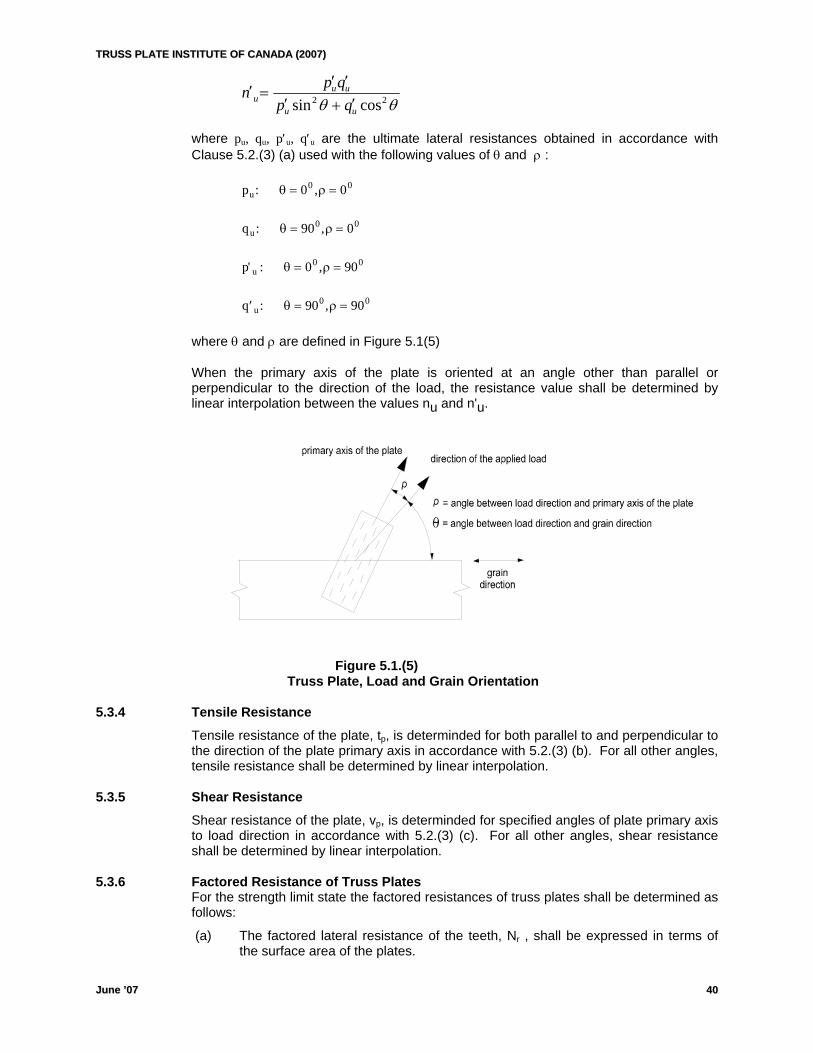
TTRRUUSSSS PPLLAATTEE IINNSSTTIITTUUTTEE OOFF CCAANNAADDAA ((22000077))
JJuunnee ’’0077 4400
θθ 22 cossin uu
uuu qp
qpn′+′′′
=′
where pu, qu, p′u, q′u are the ultimate lateral resistances obtained in accordance with Clause 5.2.(3) (a) used with the following values of θ and ρ :
p u0 0: 0 0θ ρ= =,
q u0 0: 90 , 0θ ρ= =
p ' : 0 0u0 0θ ρ= =, 9
′ = =q u0 0: 90 , 90θ ρ
where θ and ρ are defined in Figure 5.1(5)
When the primary axis of the plate is oriented at an angle other than parallel or perpendicular to the direction of the load, the resistance value shall be determined by linear interpolation between the values nu and n'u.
Figure 5.1.(5) Truss Plate, Load and Grain Orientation 5.3.4 Tensile Resistance Tensile resistance of the plate, tp, is determinded for both parallel to and perpendicular to
the direction of the plate primary axis in accordance with 5.2.(3) (b). For all other angles, tensile resistance shall be determined by linear interpolation.
5.3.5 Shear Resistance
Shear resistance of the plate, vp, is determinded for specified angles of plate primary axis to load direction in accordance with 5.2.(3) (c). For all other angles, shear resistance shall be determined by linear interpolation.
5.3.6 Factored Resistance of Truss Plates For the strength limit state the factored resistances of truss plates shall be determined as
follows:
(a) The factored lateral resistance of the teeth, Nr , shall be expressed in terms of the surface area of the plates.
TTRRUUSSSS PPLLAATTEE IINNSSTTIITTUUTTEE OOFF CCAANNAADDAA ((22000077))
JJuunnee ’’0077 4411
H N N Jr u= φ where φ = 0.9 Nu = nu(KDKSFKT)
JH = moment factor for heel connection (Clause 5.5.7.(1) or (2))
(b) The factored tensile resistance of the plates, Tr , shall be expressed in terms of the dimension of the plate measured perpendicular to the line of action of the applied forces.
Tr = φ tp where φ = 0.6
tp = tensile resistance of the plate (Clause 5.3.4)
(c) The factored shear resistance of the plates, Vr , shall be expressed in terms of the dimension of the plate measured along the line of action of the shearing forces.
Vr = φ vp
where φ = 0.6 vp = shear resistance of the plate. (Clause 5.3.5)
5.4 Serviceability Limit States Truss plate joints shall be designed such that for the serviceability limit state the effect of
specified loads is less than or equal to the lateral slip resistance of the teeth. 1) Lateral Slip Resistance
The lateral slip resistance of the teeth, ns, shall be calculated as follows:
(a) For loads parallel to the primary axis of the plate
θθ 22 cossin ss
sss qp
qpn+
=
and
(b) For loads perpendicular to the primary axis of the plate
θθ 22 cossin ss
sss qp
qpn′+′′′
=′
where ps, qs, p′s, q′s are the lateral slip resistances obtained in accordance with Clause 5.2.(4) used with the following values of θ and ρ:
p : 0 0s0 0θ ρ= =,
q : 90 , 0s0 0θ ρ= =
′ = =p : 0 , 90s0 0θ ρ
′ =q : = 90 , 90s0 0θ ρ
where ρ and θ are defined in Figure 5.1.(5)
When the primary axis of the plate is oriented at an angle other than parallel or perpendicular to the direction of the load, the resistance value shall be determined by linear interpolation between the values ns and n′s.
TTRRUUSSSS PPLLAATTEE IINNSSTTIITTUUTTEE OOFF CCAANNAADDAA ((22000077))
JJuunnee ’’0077 4422
2) For the serviceability limit state, the lateral slip resistance of the teeth, Nrs, shall be
determined as follows: Nrs = nsKSF Where KSF is the same as for strength limit state Table 5.3.2.(2)
5.5 Member Joint Connections
5.5.1 Connection of Tension Members 1) The factored lateral resistance, Nr, in each tension member must be a minimum of 100%
of the factored axial load in the member. 2) There must be sufficient factored tensile resistance, Tr, in the connector plates to transmit
the full factored axial load in each tension member, considering the appropriate planes of action.
5.5.2 Connection of Compression Members 1) Metal connector plates resisting factored compressive axial loads shall be sized to
provide factored lateral resistance, Nr, equal to the vectorial sum of no less than 50% of the component factored loads normal to the wood member interface, and 100% of the component factored loads parallel to the wood member interface.
2) Truss plates shall not be considered to transfer compression loads at joints. 5.5.3 Connection of Members for Shear 1) There must be sufficient factored lateral resistance of the teeth, Nr, in webs and chords to
transmit the factored shear loads at a joint.
2) There must be sufficient factored shear resistance, Vr, in the truss plates to transmit the factored shear loads at a joint.
5.5.4 Combined Shear-Tension Resistance The combined factored shear and tension resistance,CST, of the metal connector plate in
the contact area of webs and chords, shall be determined as follows: ( )C ST L ST LST L1 1 L2 2= +
where;
STL1 - combined factored shear/tension resistance of the pair of metal connector plates through the line of contact L1. (see Figure 5.5.4)
L1 - length of effective steel at the horizontal edge of the member under consideration.
STL2 - combined factored shear/tension resistance of the pair of metal connector plates through line of contact L2.
L2 - length of effective steel at the vertical edge of the member under consideration.
STL1 = ( )V90
T VrL11
rL1 rL1+ ⎛⎝⎜
⎞⎠⎟
−θ
STL2 = ( )T90
V TrL21
rL2 rL2+ ⎛⎝⎜
⎞⎠⎟
−θ
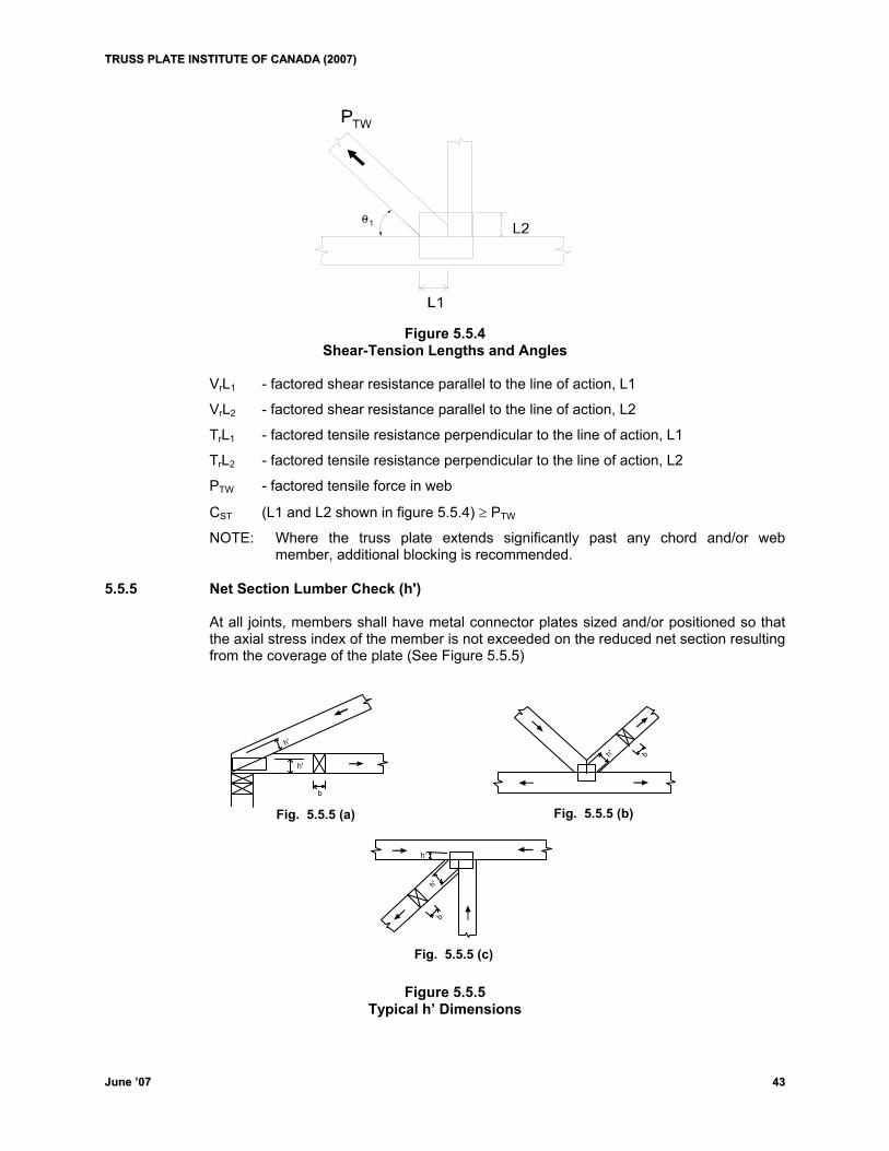
TTRRUUSSSS PPLLAATTEE IINNSSTTIITTUUTTEE OOFF CCAANNAADDAA ((22000077))
JJuunnee ’’0077 4433
Figure 5.5.4
Shear-Tension Lengths and Angles VrL1 - factored shear resistance parallel to the line of action, L1
VrL2 - factored shear resistance parallel to the line of action, L2
TrL1 - factored tensile resistance perpendicular to the line of action, L1
TrL2 - factored tensile resistance perpendicular to the line of action, L2
PTW - factored tensile force in web
CST (L1 and L2 shown in figure 5.5.4) ≥ PTW
NOTE: Where the truss plate extends significantly past any chord and/or web member, additional blocking is recommended.
5.5.5 Net Section Lumber Check (h') At all joints, members shall have metal connector plates sized and/or positioned so that
the axial stress index of the member is not exceeded on the reduced net section resulting from the coverage of the plate (See Figure 5.5.5)
h'
h'
b
h' b
h'
b
h'
Fig. 5.5.5 (a) Fig. 5.5.5 (b)
Fig. 5.5.5 (c)
Figure 5.5.5 Typical h’ Dimensions
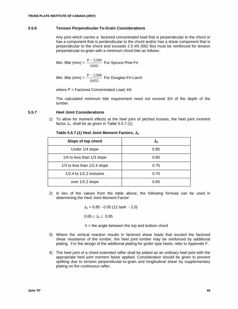
TTRRUUSSSS PPLLAATTEE IINNSSTTIITTUUTTEE OOFF CCAANNAADDAA ((22000077))
JJuunnee ’’0077 44
5.5.6 Tension Perpendicular-To-Grain Considerations Any joint which carries a factored concentrated load that is perpendicular to the chord or
has a component that is perdendicular to the chord and/or has a shear component that is perpendicular to the chord and exceeds 2.5 kN (562 lbs) must be reinforced for tension perpendicular-to-grain with a minimum chord bite as follows:
Min. Bite (mm) = P − 2 5000 041
..
For Spruce-Pine-Fir
Min. Bite (mm) = P − 2 5000 055
..
For Douglas-Fir-Larch
where P = Factored Concentrated Load, kN The calculated minimum bite requirement need not exceed 3/4 of the depth of the
lumber. 5.5.7 Heel Joint Considerations 1) To allow for moment effects at the heel joint of pitched trusses, the heel joint moment
factor JH shall be as given in Table 5.5.7.(1)
Table 5.5.7.(1) Heel Joint Moment Factors, JH
Slope of top chord JH
Under 1/4 slope 0.85
1/4 to less than 1/3 slope 0.80
1/3 to less than 1/2.4 slope 0.75
1/2.4 to 1/2.2 inclusive 0.70
over 1/2.2 slope 0.65
2) In lieu of the values from the table above, the following formula can be used in
determining the Heel Joint Moment Factor: JH = 0.85 - 0.05 (12 tanθ - 2.0) 0.65 ≤ JH ≤ 0.85 θ = the angle between the top and bottom chord 3) Where the vertical reaction results in factored shear loads that exceed the factored
shear resistance of the lumber, the heel joint lumber may be reinforced by additional plating. For the design of the additional plating for girder type heels, refer to Appendix F.
4) The heel joint of a chord extended rafter shall be plated as an ordinary heel joint with the
appropriate heel joint moment factor applied. Consideration should be given to prevent splitting due to tension perpendicular-to-grain and longitudinal shear by supplementary plating on the continuous rafter.
44
TTRRUUSSSS PPLLAATTEE IINNSSTTIITTUUTTEE OOFF CCAANNAADDAA ((22000077))
JJuunnee ’’0077 4455
5.5.8 Chord Member Splice Considerations 5.5.8.1 General For all chord splices the plate width shall be at least 65% of the width of the chord
member. 5.5.8.2 Tension Splices 1) When determining the factored tensile resistance of the metal connector plate, the
maximum extension of the metal connector plate for an unblocked chord splice is 13 mm (1/2”).
2) In the case of blocked tension splices, the total plate effectiveness shall be modified by the factor K as defined by the following equation:
K = 0.97e
-0.001(3.937 + 0.0186(88.9-h))X
where:
h = Actual width of wood member, mm. X = Extension of plate above member. Maximum X allowed in this calculation is 89
mm (3.5”).
Note: (1) For an un-blocked tension splice with an extension of 13mm (1/2”) or less, K is equal to 1.00
(2) In the case of a splice occurring at the panel joint, webs framing into joint shall be considered as blocking.
(3) Maximum plate width to be applied with effectiveness factor K cannot be in excess of the member actual width h, plus the maximum extension, X.
5.5.8.3 Compression Splices
1) Compression splice plates shall be designed so that the factored ultimate lateral resistance in each member will be at least equal to 65% of the factored compressive axial load.
2) In plumb cut compression joints the metal connector plates resisting factored compressive axial loads shall be sized to provide factored ultimate lateral resistance, equal to the vectorial sum of no less than 65% of the component factored loads normal to the wood member interface and 100% of the component factored loads parallel to the wood member interface.
5.5.8.4 Moment Considerations When in line members terminate at a splice,where chord moment should be considered,
the splice plates must have sufficient resistance to transfer this factored bending moment in addition to the factored axial load. This resistance is in both plate steel section clause 5.5.8.4.1 and plate tooth gripping clause 5.5.8.4.2. See also clause 4.6.2
TTRRUUSSSS PPLLAATTEE IINNSSTTIITTUUTTEE OOFF CCAANNAADDAA ((22000077))
JJuunnee ’’0077 44
5.5.8.4.1 Design of Steel Section for Effect of Moment.
The factored moment resistance in combination with tension MTr, of a pair of connector
plates at a splice joint shall be taken as: MTr = 0.27 tp (0.5wbr + y)2 + 0.18 b C(0.5d – y)2 – Tf y
0.5bCtt0.5w1.85T 0.25bdC
yp
pbrf
+
−+=
where: tp = corrected tensile resistance of the connector plates, N/mm
wbr = effective plate width for steel section calculations, mm (clause 5.5.8.2)
y = distance from the chord centreline to neutral axis of wood/steel combination , mm (y can be positive or negative but the moment formula is invalid if y lies outside the plate)
b = chord thickness, mm C = Fc, MPa Fc = fc(KDKScKTKZc) d = chord depth, mm
Tf = factored tension force in chord at the splice (set equal to zero for compression), N
The stress ratio for moment in combination with axial tension shall be taken as the
following:
1.0MM
Tr
f ≤
where Mf = factored bending moment in the chord at the splice, N-mm The stress ratio for the axial tension shall be taken as the following:
1.0w*T
T
brr
f ≤
where Tr = factored tension-only resistance of the connector plate, N/mm
66
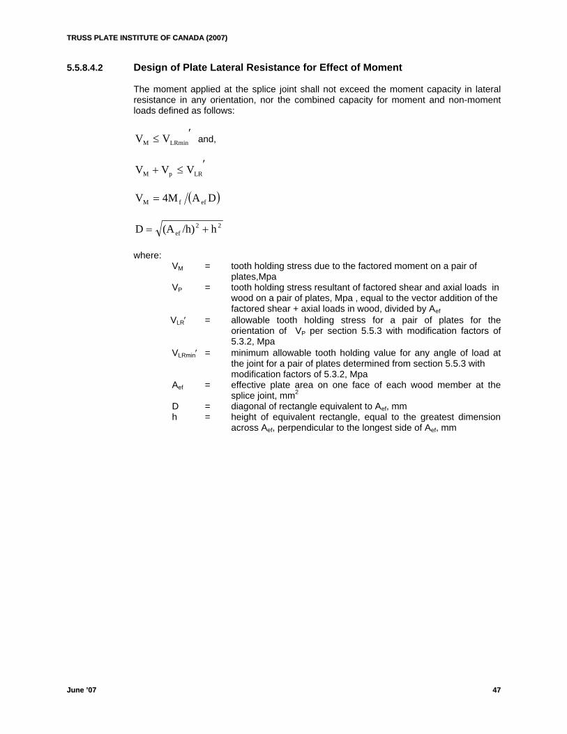
TTRRUUSSSS PPLLAATTEE IINNSSTTIITTUUTTEE OOFF CCAANNAADDAA ((22000077))
JJuunnee ’’0077 44
5.5.8.4.2 Design of Plate Lateral Resistance for Effect of Moment
The moment applied at the splice joint shall not exceed the moment capacity in lateral resistance in any orientation, nor the combined capacity for moment and non-moment loads defined as follows:
′≤ LRminM VV and,
′≤+ LRpM VVV
( )DA4MV effM =
22ef h/h)(AD +=
where:
VM = tooth holding stress due to the factored moment on a pair of plates,Mpa VP = tooth holding stress resultant of factored shear and axial loads in wood on a pair of plates, Mpa , equal to the vector addition of the factored shear + axial loads in wood, divided by Aef
VLR′ = allowable tooth holding stress for a pair of plates for the orientation of VP per section 5.5.3 with modification factors of 5.3.2, Mpa
VLRmin′ = minimum allowable tooth holding value for any angle of load at the joint for a pair of plates determined from section 5.5.3 with
modification factors of 5.3.2, Mpa Aef = effective plate area on one face of each wood member at the
splice joint, mm2
D = diagonal of rectangle equivalent to Aef, mm h = height of equivalent rectangle, equal to the greatest dimension
across Aef, perpendicular to the longest side of Aef, mm
77
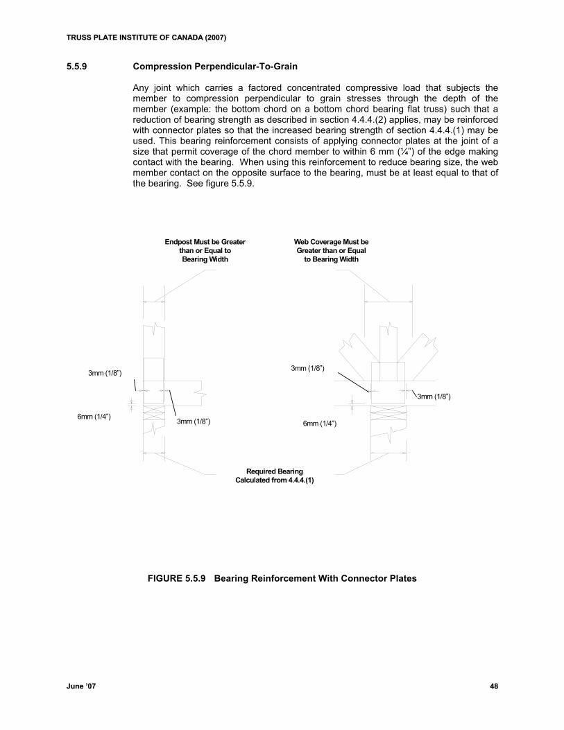
TTRRUUSSSS PPLLAATTEE IINNSSTTIITTUUTTEE OOFF CCAANNAADDAA ((22000077))
JJuunnee ’’0077 4488
5.5.9 Compression Perpendicular-To-Grain Any joint which carries a factored concentrated compressive load that subjects the
member to compression perpendicular to grain stresses through the depth of the member (example: the bottom chord on a bottom chord bearing flat truss) such that a reduction of bearing strength as described in section 4.4.4.(2) applies, may be reinforced with connector plates so that the increased bearing strength of section 4.4.4.(1) may be used. This bearing reinforcement consists of applying connector plates at the joint of a size that permit coverage of the chord member to within 6 mm (¼”) of the edge making contact with the bearing. When using this reinforcement to reduce bearing size, the web member contact on the opposite surface to the bearing, must be at least equal to that of the bearing. See figure 5.5.9.
Required Bearing Calculated from 4.4.4.(1)
Endpost Must be Greater than or Equal to Bearing Width
Web Coverage Must be Greater than or Equal
to Bearing Width
3mm (1/8”)
3mm (1/8”)
6mm (1/4”) 6mm (1/4”)
3mm (1/8”)
3mm (1/8”)
FIGURE 5.5.9 Bearing Reinforcement With Connector Plates
TTRRUUSSSS PPLLAATTEE IINNSSTTIITTUUTTEE OOFF CCAANNAADDAA ((22000077))
JJuunnee ’’0077 4499
6. Manufacturing and Material Variances Recommended quality manufacturing criteria including tollerances to allow for
manufacturing variances can be found in Appendix G.
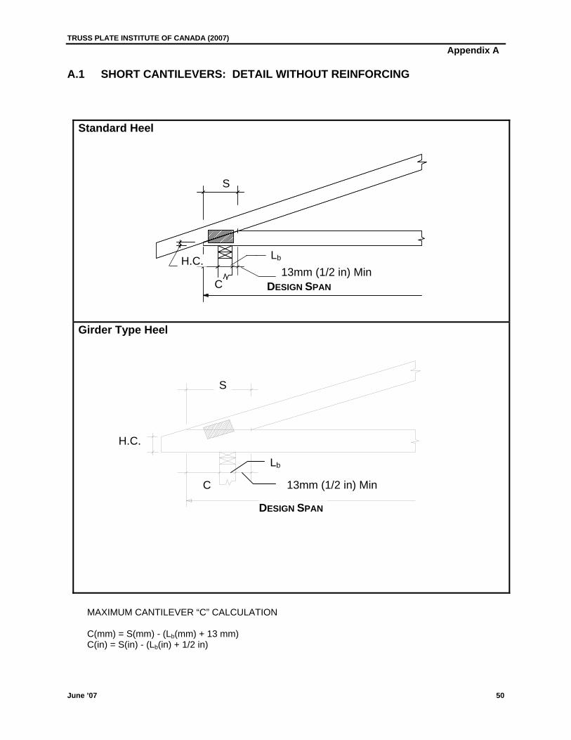
TRUSS PLATE INSTITUTE OF CANADA (2007) Appendix A
A.1 SHORT CANTILEVERS: DETAIL WITHOUT REINFORCING
Standard Heel
Girder Type Heel
S
DESIGN SPAN
H.C. Lb
13mm (1/2 in) MinC
S
H.C.
13mm (1/2 in) Min
Lb
C
DESIGN SPAN
MAXIMUM CANTILEVER “C” CALCULATION C(mm) = S(mm) - (Lb(mm) + 13 mm) C(in) = S(in) - (Lb(in) + 1/2 in)
June ’07 50
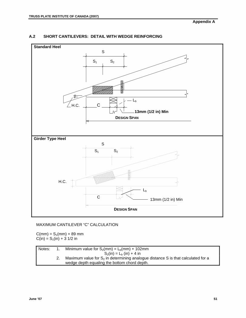
TRUSS PLATE INSTITUTE OF CANADA (2007) Appendix A A.2 SHORT CANTILEVERS: DETAIL WITH WEDGE REINFORCING
Standard Heel
S
S1 S2
Girder Type Heel
C
DESIGN SPAN
H.C. 13mm (1/2 in) Min
Lb
S S2S1
H.C.
Lb
C 13mm (1/2 in) Min
DESIGN SPAN
MAXIMUM CANTILEVER “C” CALCULATION C(mm) = S1(mm) + 89 mm C(in) = S1(in) + 3 1/2 in
Notes: 1. Minimum value for S2(mm) = Lb(mm) + 102mm S2(in) = Lb (in) + 4 in
2. Maximum value for S2 in determining analogue distance S is that calculated for a wedge depth equaling the bottom chord depth.
June ’07 51

TRUSS PLATE INSTITUTE OF CANADA (2007) Appendix A
A.3 SHORT CANTILEVERS: DETAIL WITH PARTIAL TOP CHORD REINFORCING MEMBER (PARTIAL TOP CHORD SLIDER)
Standard Heel
S
S1 S2
LT
Y
H.C. LbC
Girder-Type Heel
13mm (1/2 in) Min. DESIGN SPAN
S
S1 S2
LT
Y
H.C.
13 mm (1/2 in) Min
Lb
C
DESIGN SPAN
MAXIMUM CANTILEVER “C” CALCULATION C(mm) = S1(mm) + S2(mm) - (Lb(mm) + 13 mm) C(in) = S1(in) + S2(in) - (Lb(in)+ 1/2 in)
Notes: 1. Maximum value of S2 is limited by maximum reinforcing member size 38x184 (2x8)
2. LT = Minimum of one half the length of top chord panel 3. Y = Minimum of 25 mm (1 in)
June ’07 52
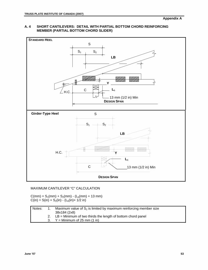
TRUSS PLATE INSTITUTE OF CANADA (2007) Appendix A
A. 4 SHORT CANTILEVERS: DETAIL WITH PARTIAL BOTTOM CHORD REINFORCING MEMBER (PARTIAL BOTTOM CHORD SLIDER)
STANDARD HEEL
S
S1 S2
LB
Y
C Lb
DESIGN SPAN
H.C. 13 mm (1/2 in) Min
Girder-Type Heel S
S1 S2
LB
H.C. Y
13 mm (1/2 in) Min
Lb
C
DESIGN SPAN
MAXIMUM CANTILEVER “C” CALCULATION C(mm) = S1(mm) + S2(mm) - (Lb(mm) + 13 mm) C(in) = S(in) + S2(in) - (Lb(in)+ 1/2 in)
Notes: 1. Maximum value of S2 is limited by maximum reinforcing member size 38x184 (2x8)
2. LB = Minimum of two thirds the length of bottom chord panel 3. Y = Minimum of 25 mm (1 in)
June ’07 53
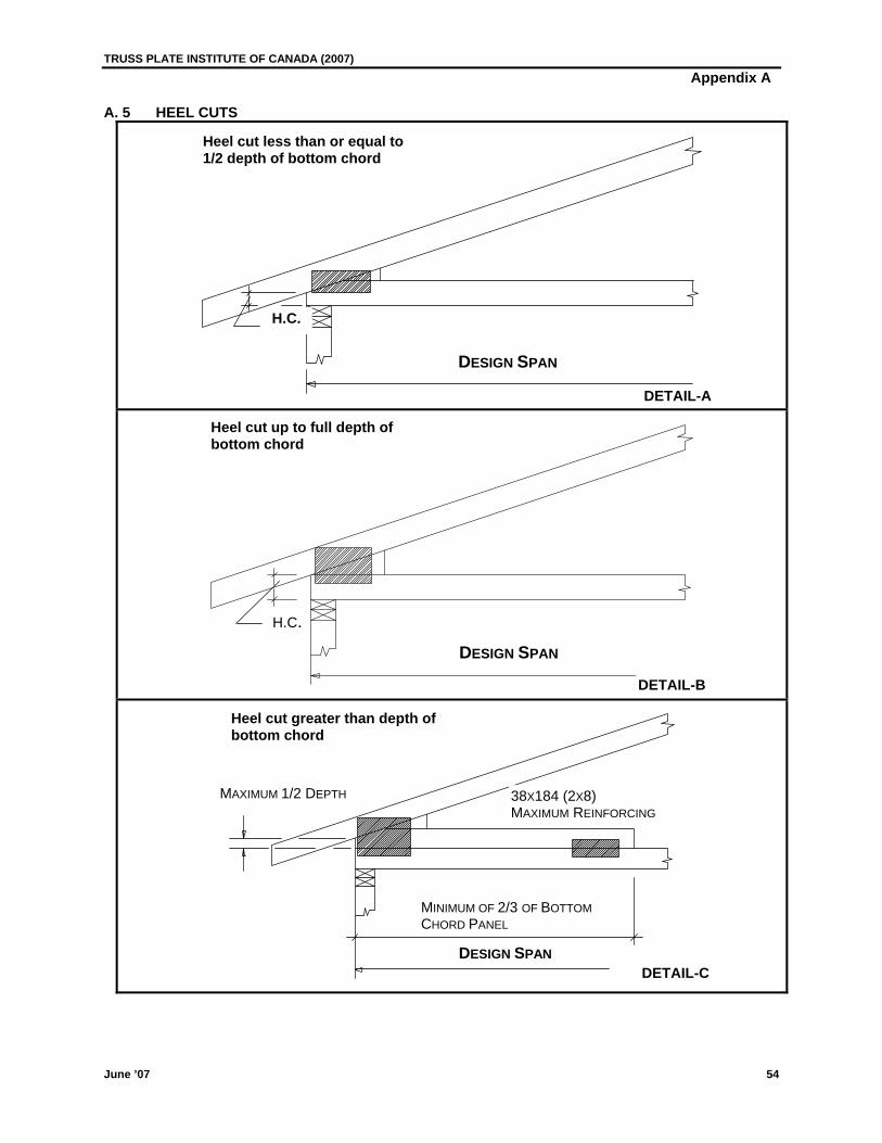
TRUSS PLATE INSTITUTE OF CANADA (2007) Appendix A
A. 5 HEEL CUTS
Heel cut less than or equal to 1/2 depth of bottom chord
H.C.
DESIGN SPAN
DETAIL-A
Heel cut up to full depth of bottom chord
H.C.
DESIGN SPAN
DETAIL-B
Heel cut greater than depth of bottom chord
MAXIMUM 1/2 DEPTH 38X184 (2X8) MAXIMUM REINFORCING
MINIMUM OF 2/3 OF BOTTOM CHORD PANEL
DESIGN SPANDETAIL-C
June ’07 54
TRUSS PLATE INSTITUTE OF CANADA (2007) Appendix A
June ’07 55
A.6 SUPPLEMENTARY NOTES FOR DESIGN OF SHORT CANTILEVERS AND HEEL CUTS 1. GENERAL a. Design span is always out to out of bottom chord for standard details. b. The sum of cantilever lengths shall not exceed 25% of span between bearings. c. Maximum cantilever shall not exceed 1372 mm (4´-6"). d. The TPIC standard procedures for plating heel joints shall apply. i.e. Reduction of grip value with
slope increase. e. Partial reinforcing members used with short cantilevers and heel cuts are limited in scope to
trusses designed under Section 4.4.13. The reinforcing members shall be designed for top or bottom chord forces as applicable. For all other applications these cantilevers and heel cuts must be accomplished by full length reinforcement of the appropriate chord and limitations of cantilever length, reinforcement size, species, grade and, plating to be determined by analysis.
2. SHORT CANTILEVER a. All details: Maximum values of ‘C’ must be calculated for specific slope and heel cut as shown on the
details. b. Detail without reinforcing. Plate heel for actual chord force. Tie plate is recommended for long scarf cuts. c. Detail with wedge reinforcing. Plate heel for actual forces. Tie plates are always required with the wedge. Total area of tie
plates on chords shall be 20% of required area of heel plate on corresponding chord. d. Detail with chord reinforcing: i. Plates joining reinforcing member to parallel chord shall provide sufficient grip and shear
length to transfer full chord force to reinforcing member. Where only one plate is used, it shall be designed for 1.20 times chord force.
ii. Heel shall be designed as per standard heel procedures. Reinforcing member may be considered as top or bottom chord as applicable. There shall be a minimum of 25 mm (1 in) overlap as shown in sketches.
iii. Where plating and scarf permit, the reinforcing member may form part of the heel cut. iv. Tie plates are recommended for long scarfs.
3. HEEL CUTS a. Detail A. Heel cut less than or equal to 6mm (1/4 in.) may be considered as zero heel cut. Plate for full
chord forces. b. Detail B. Plate heel to resist full chord forces at 1/2 bottom chord depth with linear interpolation to twice the
full chord forces up to the full depth of bottom chord. c. Detail C. Plate heel for full chord forces. Plate design for connecting reinforcing member to parallel chord
shall be as per 2d.i. above.

TRUSS PLATE INSTITUTE OF CANADA (1996) Appendix B
June ’07 56
B. 1 TRUSS-TO-TRUSS CONNECTION
Length of nail 76 mm (3.00") Lumber Grade Spruce-Pine-Fir Minimum nail spacing parallel to grain (a) 64 mm (2.50") Minimum nail spacing from End distance 45 mm (1.75") parallel to grain (b) Minimum nail spacing perpendicular to grain (c) 32 mm (1.25") Minimum nail spacing from edge distance 19 mm (0.75") perpendicular to grain (d)
MEMBER DEPTH
mm (inches)
MAXIMUM
NO. OF ROWS
MINIMUM *
NO. OF ROWS
64 (2.5)
89 (3.5)
114 (4.5)
140 (5.5)
184 (7.25)
235 (9.25)
286 (11.25)
1
2
2
3
4
5
6
1
1
1
2
2
3
3
* For web nailing, use minimum number of rows stated in table and a surface nail spacing of 150 mm (6") o.c.
Table B.1.1 Nail Spacing and Maximum Number of Rows.
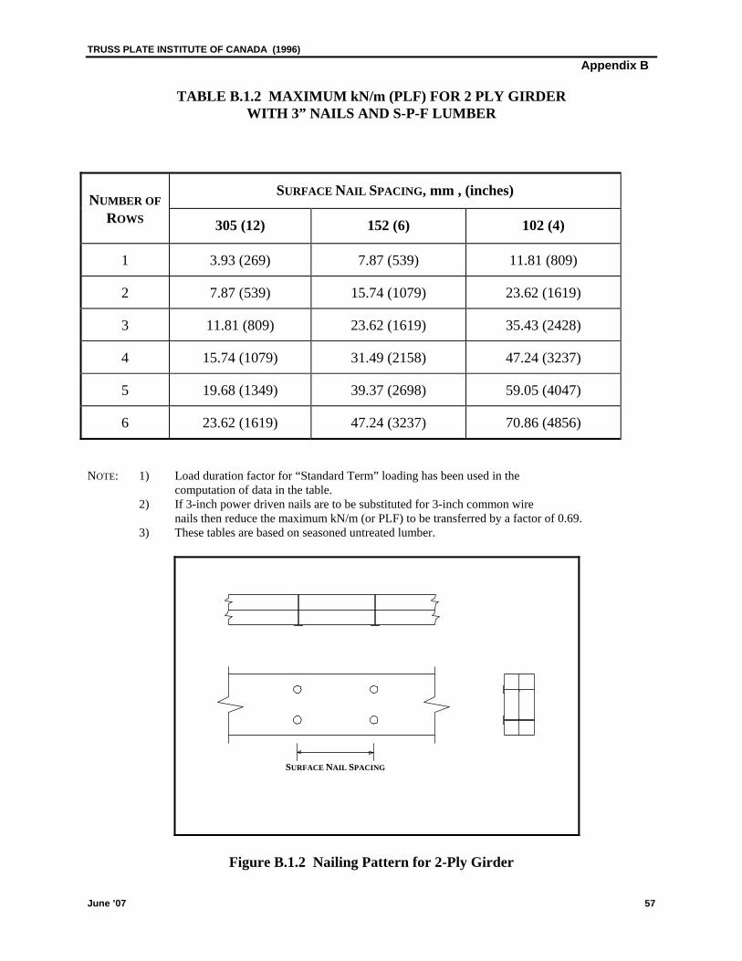
TRUSS PLATE INSTITUTE OF CANADA (1996) Appendix B
June ’07 57
TABLE B.1.2 MAXIMUM kN/m (PLF) FOR 2 PLY GIRDER WITH 3” NAILS AND S-P-F LUMBER
NUMBER OF
SURFACE NAIL SPACING, mm , (inches)
ROWS 305 (12) 152 (6) 102 (4)
1 3.93 (269) 7.87 (539) 11.81 (809)
2 7.87 (539) 15.74 (1079) 23.62 (1619)
3 11.81 (809) 23.62 (1619) 35.43 (2428)
4 15.74 (1079) 31.49 (2158) 47.24 (3237)
5 19.68 (1349) 39.37 (2698) 59.05 (4047)
6 23.62 (1619) 47.24 (3237) 70.86 (4856)
NOTE: 1) Load duration factor for “Standard Term” loading has been used in the computation of data in the table. 2) If 3-inch power driven nails are to be substituted for 3-inch common wire
nails then reduce the maximum kN/m (or PLF) to be transferred by a factor of 0.69. 3) These tables are based on seasoned untreated lumber.
Figure B.1.2 Nailing Pattern for 2-Ply Girder
SURFACE NAIL SPACING
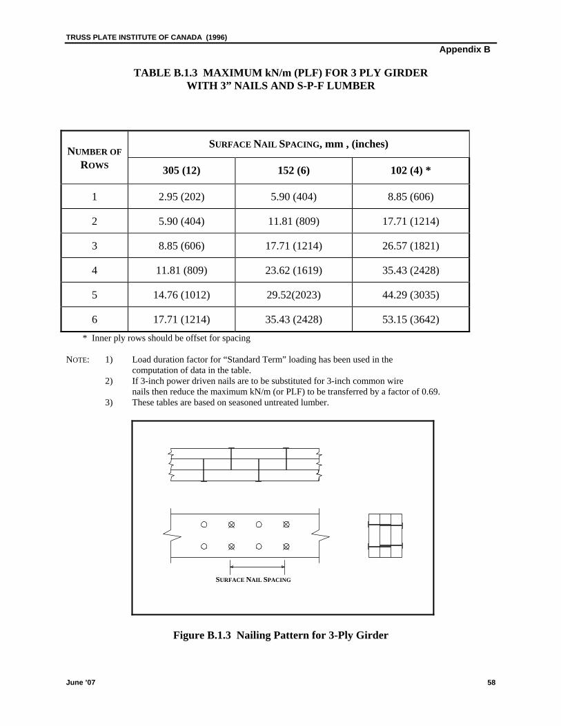
TRUSS PLATE INSTITUTE OF CANADA (1996) Appendix B
June ’07 58
TABLE B.1.3 MAXIMUM kN/m (PLF) FOR 3 PLY GIRDER WITH 3” NAILS AND S-P-F LUMBER
NUMBER OF
SURFACE NAIL SPACING, mm , (inches)
ROWS 305 (12) 152 (6) 102 (4) *
1 2.95 (202) 5.90 (404) 8.85 (606)
2 5.90 (404) 11.81 (809) 17.71 (1214)
3 8.85 (606) 17.71 (1214) 26.57 (1821)
4 11.81 (809) 23.62 (1619) 35.43 (2428)
5 14.76 (1012) 29.52(2023) 44.29 (3035)
6 17.71 (1214) 35.43 (2428) 53.15 (3642) * Inner ply rows should be offset for spacing
NOTE: 1) Load duration factor for “Standard Term” loading has been used in the computation of data in the table. 2) If 3-inch power driven nails are to be substituted for 3-inch common wire
nails then reduce the maximum kN/m (or PLF) to be transferred by a factor of 0.69. 3) These tables are based on seasoned untreated lumber.
Figure B.1.3 Nailing Pattern for 3-Ply Girder
SURFACE NAIL SPACING

TRUSS PLATE INSTITUTE OF CANADA (1996) Appendix B
June ’07 59
TABLE B.1.4 MAXIMUM kN/m (PLF) FOR 4 PLY GIRDER WITH 3" NAILS AND S-P-F LUMBER
NUMBER OF
SURFACE NAIL SPACING , mm , (inches)
ROWS 305 (12) 152 (6) 102 (4)*
1 2.62 (179) 5.24 (359) 7.87 (539)
2 5.24 (359) 10.49 (719) 15.74 (1079)
3 7.87 (539) 15.74 (1079) 23.62 (1619)
4 10.49 (719) 20.99 (1439) 31.49 (2158)
5 13.12 (899) 26.24 (1798) 39.37 (2698)
6 15.74 (1079) 31.49 (2158) 47.24 (3237) * Inner ply rows should be offset for spacing
NOTE: 1) Load duration factor for “Standard Term” loading has been used in the computation of data in the table. 2) If 3-inch power driven nails are to be substituted for 3-inch common wire
nails then reduce the maximum kN/m (or PLF) to be transferred by a factor of 0.69. 3) These tables are based on seasoned untreated lumber.
Figure B.1.4 Nailing Pattern for 4-Ply Girder Supplementary Notes:
In addition to nailing, all chords of 4 ply girders must be bolted together with 13 mm (0.5") bolts and washers, 1 bolt per panel.
SURFACE NAIL SPACING
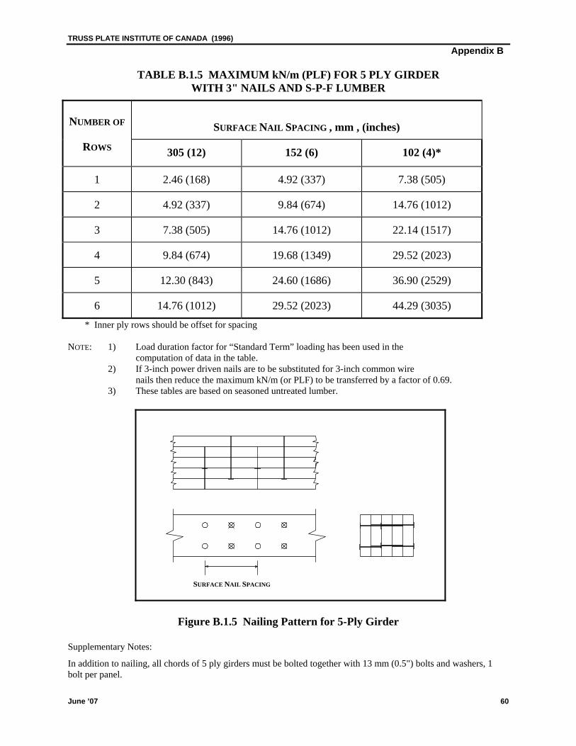
TRUSS PLATE INSTITUTE OF CANADA (1996) Appendix B
June ’07 60
TABLE B.1.5 MAXIMUM kN/m (PLF) FOR 5 PLY GIRDER WITH 3" NAILS AND S-P-F LUMBER
NUMBER OF
SURFACE NAIL SPACING , mm , (inches)
ROWS 305 (12) 152 (6) 102 (4)*
1 2.46 (168) 4.92 (337) 7.38 (505)
2 4.92 (337) 9.84 (674) 14.76 (1012)
3 7.38 (505) 14.76 (1012) 22.14 (1517)
4 9.84 (674) 19.68 (1349) 29.52 (2023)
5 12.30 (843) 24.60 (1686) 36.90 (2529)
6 14.76 (1012) 29.52 (2023) 44.29 (3035) * Inner ply rows should be offset for spacing
NOTE: 1) Load duration factor for “Standard Term” loading has been used in the computation of data in the table. 2) If 3-inch power driven nails are to be substituted for 3-inch common wire
nails then reduce the maximum kN/m (or PLF) to be transferred by a factor of 0.69. 3) These tables are based on seasoned untreated lumber.
Figure B.1.5 Nailing Pattern for 5-Ply Girder
Supplementary Notes:
In addition to nailing, all chords of 5 ply girders must be bolted together with 13 mm (0.5") bolts and washers, 1 bolt per panel.
SURFACE NAIL SPACING
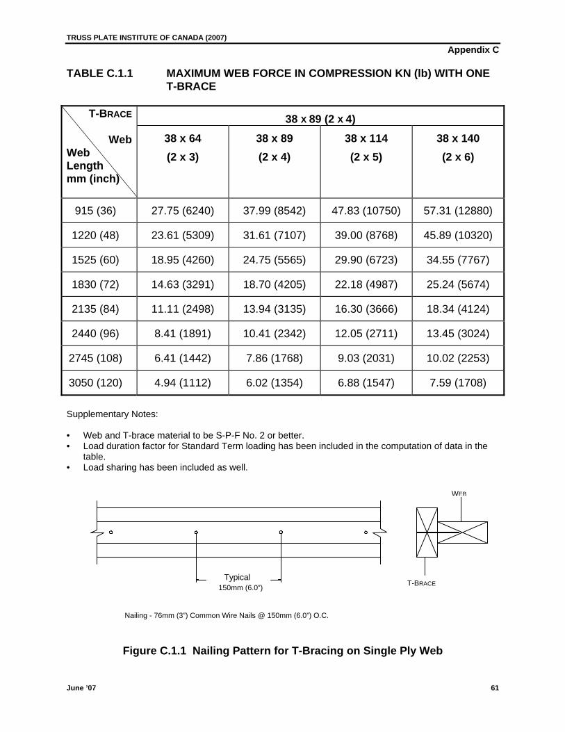
TRUSS PLATE INSTITUTE OF CANADA (2007) Appendix C
TABLE C.1.1 MAXIMUM WEB FORCE IN COMPRESSION KN (lb) WITH ONE T-BRACE
38 X 89 (2 X 4) T-BRACE
Web Web Length mm (inch)
38 x 64 (2 x 3)
38 x 89 (2 x 4)
38 x 114 (2 x 5)
38 x 140 (2 x 6)
915 (36) 27.75 (6240) 37.99 (8542) 47.83 (10750) 57.31 (12880)
1220 (48) 23.61 (5309) 31.61 (7107) 39.00 (8768) 45.89 (10320)
1525 (60) 18.95 (4260) 24.75 (5565) 29.90 (6723) 34.55 (7767)
1830 (72) 14.63 (3291) 18.70 (4205) 22.18 (4987) 25.24 (5674)
2135 (84) 11.11 (2498) 13.94 (3135) 16.30 (3666) 18.34 (4124)
2440 (96) 8.41 (1891) 10.41 (2342) 12.05 (2711) 13.45 (3024)
2745 (108) 6.41 (1442) 7.86 (1768) 9.03 (2031) 10.02 (2253)
3050 (120) 4.94 (1112) 6.02 (1354) 6.88 (1547) 7.59 (1708)
Supplementary Notes: • Web and T-brace material to be S-P-F No. 2 or better. • Load duration factor for Standard Term loading has been included in the computation of data in the
table. • Load sharing has been included as well.
WEB
Typical 150mm (6.0”)
T-BRACE
Nailing - 76mm (3”) Common Wire Nails @ 150mm (6.0”) O.C.
Figure C.1.1 Nailing Pattern for T-Bracing on Single Ply Web
June ’07 61
TRUSS PLATE INSTITUTE OF CANADA (2007)
Appendix D
June ’07 62
TABLE D.4.6.6.1 TOP CHORD BEARING JOINT GUIDELINES FOR LUMBER ON EDGE
BEARING DETAIL
SEE FIGURE
TOP CHORD SIZE
DIAGONAL SIZE MIN
MAXIMUM FACTORED
ALLOWABLEREACTION
MAX ALLOWABLE GAP
mm (in)
D.4.6.6.1 mm (in) mm (in) kN (lbs) A B C
Detail 1 38 x 89 (2x4) N/A 14.10 (3170) 13 (1/2) 13 (1/2) 3 (1/8)
Detail 2 38 x 89 (2x4) N/A 14.10 (3170) N/A 13 (1/2) 13 (1/2)
Detail 3,4 38 x 89 (2x4)
38 x 114 (2x5)
38 x 140 (2x6)*
38 x 89 (2x4)
38 x 89 (2x4)
38 x 89 (2x4)
11.98 (2694)
14.80 (3328)
17.62 (3962)
13 (1/2)
13 (1/2)
13 (1/2)
13 (1/2)
38 (1-1/2)
50 (2)
3 (1/8)
3 (1/8)
3 (1/8)
Detail 5 38 x 89 (2x4)
38 x 114 (2x5)
38 x 140 (2x6)*
38 x 89 (2x4)
38 x 89 (2x4)
38 x 89 (2x4)
16.92 (3804)
19.03 (4279)
21.15 (4755)
13 (1/2)
13 (1/2)
13 (1/2)
N/A
N/A
N/A
6 (1/4)
6 (1/4)
6 (1/4)
Detail 6,7 38 x 89 (2x4)
38 x 114 (2x5)
38 x 140 (2x6)*
38 x 89 (2x4) 38 x 114 (2x5) 38 x 140 (2x6)
38 x 89 (2x4) 38 x 114 (2x5) 38 x 140 (2x6)
38 x 89 (2x4) 38 x 114 (2x5) 38 x 140 (2x6)
16.92 (3804)19.74 (4438)22.56 (5072)
17.27 (3883)21.32 (4794)25.38 (5706)
17.62 (3962)22.91 (5151)28.20 (6340)
N/A N/A N/A
N/A N/A N/A
N/A N/A N/A
13 (1/2) 13 (1/2) 13 (1/2)
38 (1-1/2)38 (1-1/2)38 (1-1/2)
50 (2) 50 (2) 50 (2)
13 (1/2) 13 (1/2) 13 (1/2)
13 (1/2) 13 (1/2) 13 (1/2)
13 (1/2) 13 (1/2) 13 (1/2)
* Or Greater
Note: Maximum factored reactions are for Spruce-Pine-Fir and D. Fir Chords.
TRUSS PLATE INSTITUTE OF CANADA (2007)
Appendix D
June ’07 63
FIGURE D.4.6.6.1 TYPICAL TOP CHORD BEARING JOINT GUIDELINES FOR LUMBER ON EDGE
DETAIL 1
DETAIL 2
DETAIL 3
DETAIL 4
DETAIL 6 DETAIL 5
DETAIL 7
A C
B C
A
BC
B C
BC
50mm (2in)minimum
A
B C
A
B C
TRUSS PLATE INSTITUTE OF CANADA (2007)
Appendix D
June ’07 64
TABLE D.4.6.6.2 TOP CHORD BEARING JOINT GUIDELINES FOR LUMBER ON FLAT
TOP CHORD BEARING
TYPE AS SHOWN IN FIGURE D.4.6.6.2
MAXIMUM FACTORED
ALLOWABLE REACTION
MAX ALLOWABLE GAP mm (in)
kN (lbs) A B C
Single Top Chord
4 x 2
Detail 1,2
Detail 3
Detail 4
4.23 (951)
11.28 (2536)
4.23 (951)
13 (1/2)
N/A
13 (1/2)
3 (1/8)
3 (1/8)
3 (1/8)
3 (1/8)
13 (1/2)
3 (1/8)
Double Top Chord
4 x 2
Detail 5, 7, 8
Detail 6
Detail 5, 6 (at B.C)
11.28 (2536)
11.28 (2536)
13 (1/2)
N/A
N/A
3 (1/8)
3 (1/8)
3 (1/8)
3 (1/8)
13 (1/2)
3 (1/8)
Double Top Chord
3 x 2
Detail 7, 8 8.06 (1811) 13 (1/2) 3 (1/8) 3 (1/8)
Double Top Chord
4 x 2
Detail 9,10 28.20 (6340) N/A 3 (1/8) 13 (1/2)
Note: Maximum factored reactions are for Spruce-Pine-Fir and D. Fir Chords
TRUSS PLATE INSTITUTE OF CANADA (2007)
Appendix D
June ’07 65
FIGURE D.4.6.6.2 TYPICAL TOP CHORD BEARING JOINT GUIDELINES FOR LUMBER ON FLAT
DETAIL 1
DETAIL 2
DETAIL 3
DETAIL 4
DETAIL 6 DETAIL 5
DETAIL 7
DETAIL 8
A
BC
B C
B C
A
B C
A
B C
B
B C
C
A
B C
A
C
B C
B
A
B
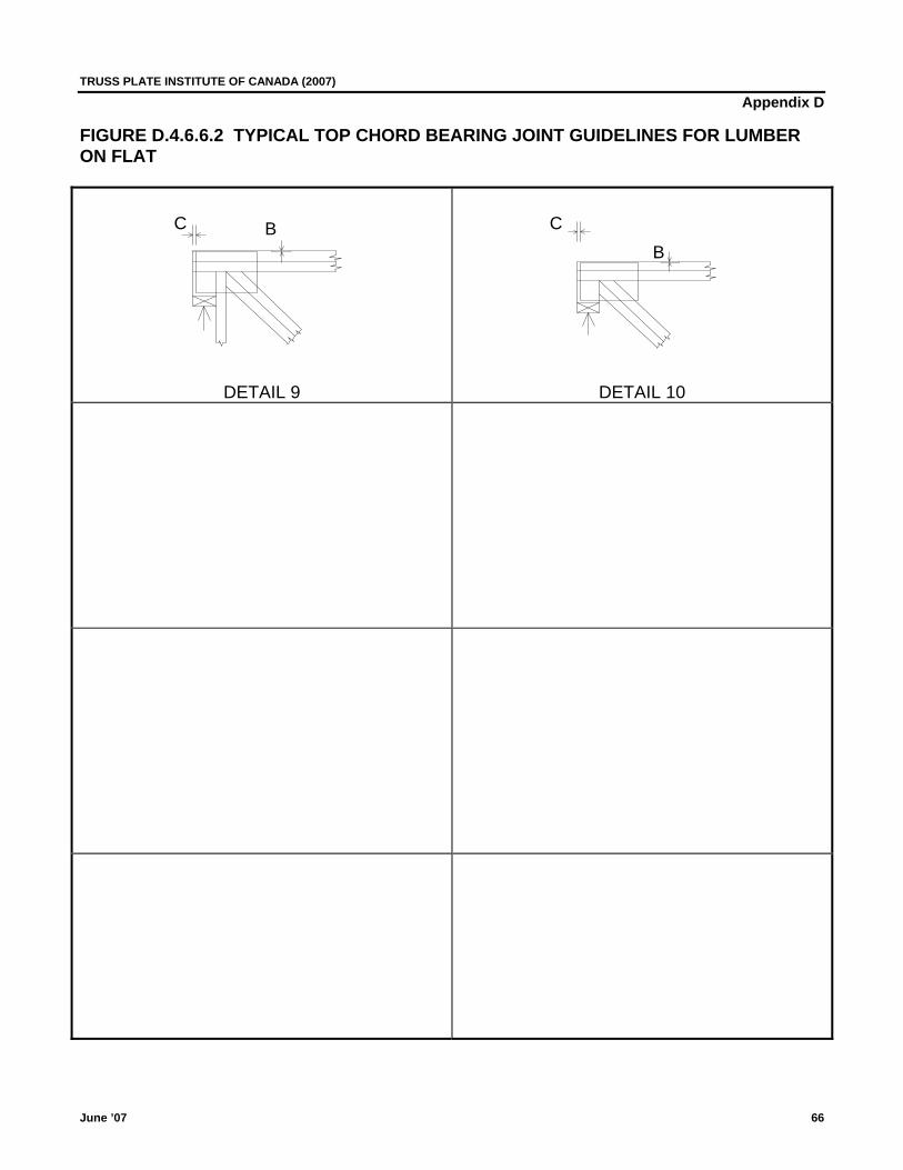
TRUSS PLATE INSTITUTE OF CANADA (2007)
Appendix D
June ’07 66
FIGURE D.4.6.6.2 TYPICAL TOP CHORD BEARING JOINT GUIDELINES FOR LUMBER ON FLAT
DETAIL 9
DETAIL 10
C CBB
TRUSS PLATE INSTITUTE OF CANADA (2007) Appendix E
E.1 CORROSION PROTECTION FOR METAL CONNECTOR PLATES
1. For metal connector plates used in unusual environmental conditions, or exposed to the weather, additional corrosion resistant protection for the metal connector plates shall be installed when such conditions are identified by the building designer/engineer.
2. Galvanized G 90 metal connector plates subject to environments described above shall be painted with
one coat of one of the following combinations: a) Epoxy-Polyamide Primer (SSPC-Paint22) b) Coal-Tar Epoxy-Polyamide Black or Dark Red Paint (SSPC-Paint 16) c) Basic Zinc Chromate-Vinyl Butyral Wash Primer (SSPC-Paint 27) and cold applied Asphaltic Mastic
(Extra Thick Film) Paint (SSPC-Paint 12) d) Any other coating or treatment acceptable to the building designer/engineer 3. All coatings shall be brush applied to the embedded metal connector plates at the jobsite during or after
truss installation. Embedded metal connector plates shall be free of dirt and oil prior to coating application. In addition, all of the Manufacturer’s recommendations for application of products used must be followed implicitly.
Note: To the best of industry knowledge these products will extend the serviceable life of the truss connector
plate under conditions described in 1. above. No warranty or guarantee, other than that offered by the manufacturers of these products is expressed or
implied. Severe corrosive conditions may require maintenance of these protective coatings as part of the standard building maintenance program.
June ’07 67
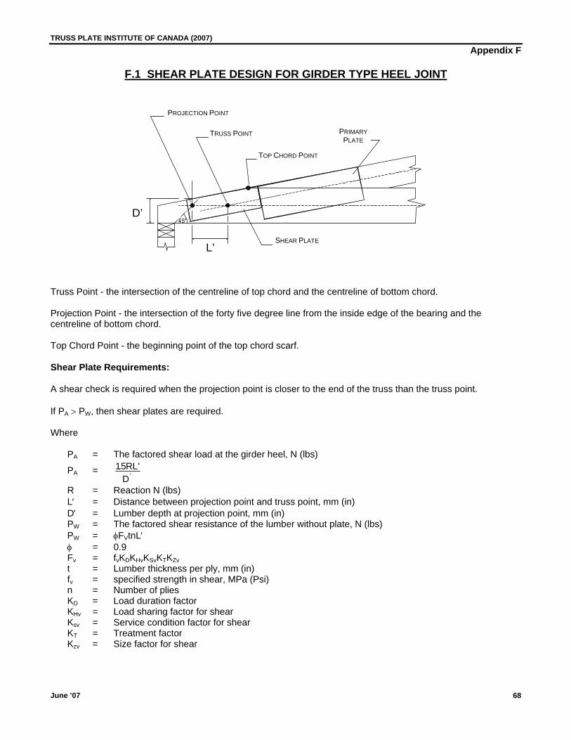
TRUSS PLATE INSTITUTE OF CANADA (2007) Appendix F
F.1 SHEAR PLATE DESIGN FOR GIRDER TYPE HEEL JOINT
PROJECTION POINT
PRIMARYPLATE
TRUSS POINT
TOP CHORD POINT
D’
SHEAR PLATEL’
Truss Point - the intersection of the centreline of top chord and the centreline of bottom chord. Projection Point - the intersection of the forty five degree line from the inside edge of the bearing and the centreline of bottom chord. Top Chord Point - the beginning point of the top chord scarf. Shear Plate Requirements: A shear check is required when the projection point is closer to the end of the truss than the truss point. If PA > PW, then shear plates are required. Where PA = The factored shear load at the girder heel, N (lbs)
PA = 15. ''
RLD
R = Reaction N (lbs) L′ = Distance between projection point and truss point, mm (in) D′ = Lumber depth at projection point, mm (in) PW = The factored shear resistance of the lumber without plate, N (lbs) PW = φFVtnL′ φ = 0.9
Fv = fvKDKHvKSvKTKZv
t = Lumber thickness per ply, mm (in) fv = specified strength in shear, MPa (Psi) n = Number of plies KD = Load duration factor KHv = Load sharing factor for shear Ksv = Service condition factor for shear KT = Treatment factor Kzv = Size factor for shear
June ’07 68
TRUSS PLATE INSTITUTE OF CANADA (2007) Appendix F
Shear Plate Design: The shear plate must be sized and placed about the centreline of bottom chord to cover the distance L′ such that: i) Area of the shear plate above or below the centreline of bottom chord must be capable of resisting the net
shear force at the girder heel.
Net Shear Force = PA PW
n−
ii) The length of the shear plate along the centreline of bottom chord must be such that the shear capacity of the
plate, along the centreline of bottom chord, is greater than or equal to the net shear force at the girder heel. The shear length as calculated must not be less than L′.
Notes: 1. Where the primary plate interferes with the placement of the secondary shear plate then the primary plate
must be specified long enough to provide the required grip and metal shear capacity due to the net shear force.
2. The tapered depth of the bottom chord at the inside edge of bearing should not be less than half the bottom
chord size or 100mm (4 in), whichever is greater. 3. An additional moment check should be carried out due to extension of the bottom chord past the top chord.
The moment to be used for this check is the overall span reaction times the distance from the inside edge of the bearing to the top chord point.
June ’07 69
TRUSS PLATE INSTITUTE OF CANADA (2007) Appendix G
June ’07 70
Recommended Quality Manufacturing Criteria
This appendix provides a method for considering manufacturing and material variances within the design criteria.
Lumber
The lumber shall meet the criteria as described in TPIC Section 2.1 and be the size, species and minimum grade specified on the Truss Shop Drawings.
Splits in any wood member caused by the manufacturing process shall not exceed those permitted in the grade and species of lumber used.
Plating
Section 5.1 in the TPIC design procedures describes the conditions for which the design criterion for truss plates is based. When these conditions cannot be achieved in the manufacturing process, it is recommended that the plate design criteria be adjusted to allow for plate misplacement and ineffective teeth. This section provides a recommended procedure to adjust the design criteria to match that which is achievable in the manufacturing process.
Metal connector plates shall be of the gauge, type, and manufacturer and at least the width and length as specified on the Truss Shop Drawing.
Placement:
The truss design software allows for the input of a plate placement tolerance. The software selects a plate size and placement for each joint that resists the lateral forces in each member. It then shifts the plate by the amount input and checks to verify that it resists the forces in each member. The plate is shifted up, down, left, right, up and left, down and left, up and right, and down and right. If the plate does not resist the force in any member, the plate size is increased and checked again for the various shift positions. Plates shall be positioned according to the Truss Shop Drawing and should be placed within the input plate placement tolerance. In no case shall the positioning decrease the number of effective teeth in any member to less than the number required for that member. Effective Teeth:
Effective teeth are teeth fully embedded normal to the surface of the lumber and into quality wood of the member and with a slot to grain orientation within 10˚ to that indicated on the Truss Shop Drawing.
TRUSS PLATE INSTITUTE OF CANADA (2007) Appendix G
June ’07 71
Ineffective Teeth: Ineffective teeth are teeth, for example, over wane, knot holes, loose or decayed knots, pitch pockets, unsound wood, holes and joint gaps or teeth that have been flattened before or during the pressing, or that have a tooth embedment gap of 1/16” or greater. Teeth located within the ½” end and ¼” edge distances of the lumber are considered to be ineffective when the design is based upon the net area method.
Partially Effective Teeth: Teeth in the area where the tooth embedment gap is greater than 1/32” but less than 1/16” shall be considered 60% effective.
When a metal connector plate is installed in the connection area of lumber which contains tooth holes from a previously installed plate and where the wood is otherwise undamaged, metal connector plate teeth shall be considered 50% effective. Minimum Effective Teeth: The truss design software provides for the input of an allowance for ineffective teeth. This allowance is input as a percentage and limits the JSI. As an example, input of an Ineffective Teeth Allowance of 10% will limit the JSI to 0.90. The average number of effective teeth for both sides of the joint in any member shall never be less than (100 - the Ineffective Teeth Allowance) % of the total number of teeth specified on the shop drawing. When averaging the effective teeth on both sides, no one side shall have less than 85% of the specified effective teeth required.
Joint Stress Index: The Joint Stress Index (JSI) is the ratio of the calculated force in a member to the lateral resisting force of the teeth in that member. Example: If a member has a design force of 900 pounds in it and the teeth of the connector plate can resist 1000 pounds, the JSI = 0.90
Metal Effectiveness:
The sum of the length or width of metal across each side of a joint (shear or tension) shall never be less that 95% of that specified on the Truss Shop Drawing.
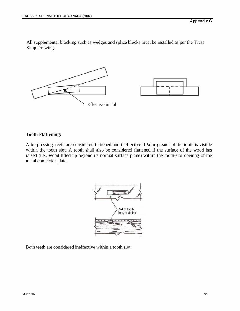
TRUSS PLATE INSTITUTE OF CANADA (2007) Appendix G
June ’07 72
All supplemental blocking such as wedges and splice blocks must be installed as per the Truss Shop Drawing.
Effective metal
Tooth Flattening:
After pressing, teeth are considered flattened and ineffective if ¼ or greater of the tooth is visible within the tooth slot. A tooth shall also be considered flattened if the surface of the wood has raised (i.e., wood lifted up beyond its normal surface plane) within the tooth-slot opening of the metal connector plate.
Both teeth are considered ineffective within a tooth slot.
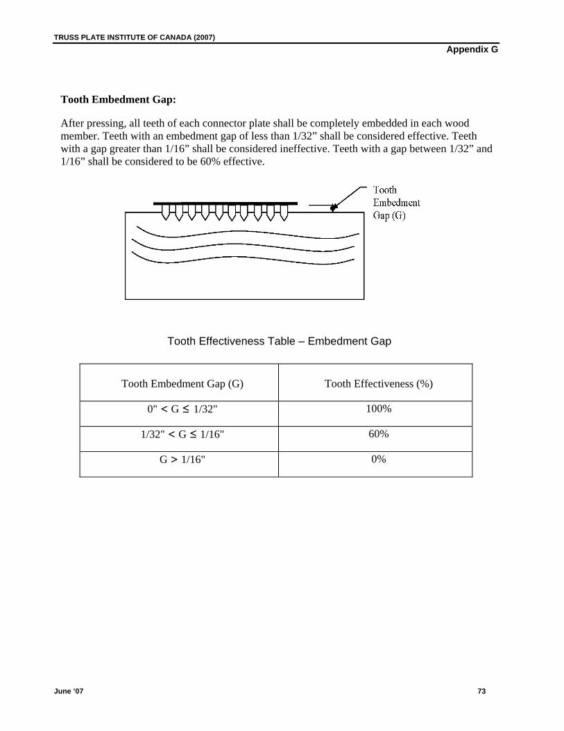
TRUSS PLATE INSTITUTE OF CANADA (2007) Appendix G
June ’07 73
Tooth Embedment Gap:
After pressing, all teeth of each connector plate shall be completely embedded in each wood member. Teeth with an embedment gap of less than 1/32” shall be considered effective. Teeth with a gap greater than 1/16” shall be considered ineffective. Teeth with a gap between 1/32” and 1/16” shall be considered to be 60% effective.
Tooth Effectiveness Table – Embedment Gap
Tooth Embedment Gap (G) Tooth Effectiveness (%)
0" < G ≤ 1/32" 100%
1/32" < G ≤ 1/16" 60%
G > 1/16" 0%
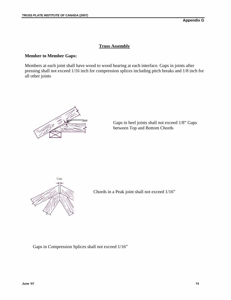
TRUSS PLATE INSTITUTE OF CANADA (2007) Appendix G
June ’07 74
Truss Assembly
Member to Member Gaps:
Members at each joint shall have wood to wood bearing at each interface. Gaps in joints after pressing shall not exceed 1/16 inch for compression splices including pitch breaks and 1/8 inch for all other joints
Gaps in heel joints shall not exceed 1/8” Gaps between Top and Bottom Chords
Chords in a Peak joint shall not exceed 1/16”
Gaps in Compression Splices shall not exceed 1/16”
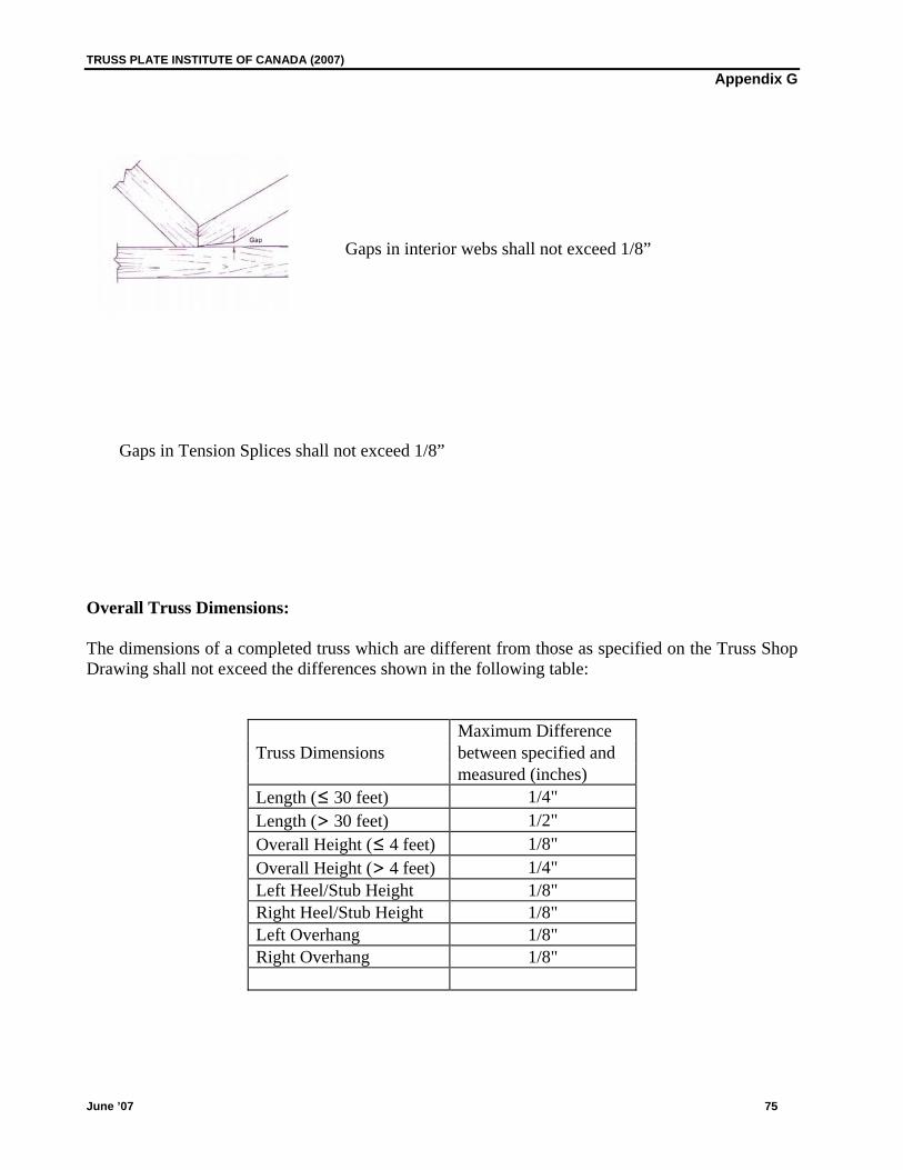
TRUSS PLATE INSTITUTE OF CANADA (2007) Appendix G
June ’07 75
Gaps in interior webs shall not exceed 1/8”
Gaps in Tension Splices shall not exceed 1/8” Overall Truss Dimensions:
The dimensions of a completed truss which are different from those as specified on the Truss Shop Drawing shall not exceed the differences shown in the following table:
Maximum Difference Truss Dimensions between specified and measured (inches) Length (≤ 30 feet) 1/4" Length (> 30 feet) 1/2" Overall Height (≤ 4 feet) 1/8" Overall Height (> 4 feet) 1/4" Left Heel/Stub Height 1/8" Right Heel/Stub Height 1/8" Left Overhang 1/8" Right Overhang 1/8"