tr 101 159 - v01.01.01 - digital enhanced cordless
TRANSCRIPT

European Telecommunications Standards Institute
TR 101 159 V1.1.1 (1998-02)Technical Report
Digital Enhanced Cordless Telecommunications (DECT);Implementing DECT in an arbitrary spectrum allocation

TR 101 159 V1.1.1 (1998-02)2
ReferenceDTR/DECT-050132 (aqc00ics.PDF)
KeywordsDECT, radio
ETSI Secretariat
Postal addressF-06921 Sophia Antipolis Cedex - FRANCE
Office address650 Route des Lucioles - Sophia Antipolis
Valbonne - FRANCETel.: +33 4 92 94 42 00 Fax: +33 4 93 65 47 16
Siret N° 348 623 562 00017 - NAF 742 CAssociation à but non lucratif enregistrée à laSous-Préfecture de Grasse (06) N° 7803/88
X.400c= fr; a=atlas; p=etsi; s=secretariat
[email protected]://www.etsi.fr
Copyright Notification
No part may be reproduced except as authorized by written permission.The copyright and the foregoing restriction extend to reproduction in all media.
© European Telecommunications Standards Institute 1998.All rights reserved.

TR 101 159 V1.1.1 (1998-02)3
Contents
Intellectual Property Rights ............................................................................................................................... 4
Foreword ............................................................................................................................................................ 4
1 Scope........................................................................................................................................................ 5
2 References ............................................................................................................................................... 5
3 Definitions and abbreviations.................................................................................................................. 73.1 Definitions ......................................................................................................................................................... 73.2 Abbreviations..................................................................................................................................................... 7
4 Introduction to DECT services and applications..................................................................................... 8
5 Requirements ......................................................................................................................................... 105.1 Carrier positions............................................................................................................................................... 105.2 General requirements....................................................................................................................................... 10
Annex A: Examples for frequency band allocations in the range 1 900 to 2 200 MHz .................. 12
A.1 Carrier allocation example for band 1 910 MHz to 1 930 MHz............................................................ 12
A.2 Carrier allocation example for band 1 900 MHz to 1 920 MHz............................................................ 12
Annex B: Examples of frequency band allocations in within 2 200 MHz to 105 GHz ................... 13
B.1 Radio frequency bands for Fixed Wireless Access (FWA) applications in the range 2 200 MHz to105 GHz................................................................................................................................................. 13
B.1.1 Definition of access channels, bearers ............................................................................................................. 13B.1.1.1 TDD ........................................................................................................................................................... 14B.1.1.2 FDD............................................................................................................................................................ 14B.1.1.3 Definition of Fc, Fd, Fcu and Fcd .............................................................................................................. 14B.1.2 Dynamic Channel Selection (DCS) algorithms................................................................................................ 14B.1.3 Antenna diversity algorithms ........................................................................................................................... 14B.1.4 Time domain offset for low cost spectrum efficient FDD applications............................................................ 15B.1.5 Operator codes, carrier number and RF-band definitions ................................................................................ 15
B.2 FWA in frequency bands in the range 3 400 - 4 200 MHz.................................................................... 15B.2.1 Duplex regimes................................................................................................................................................ 16B.2.2 The regulatory environment............................................................................................................................. 16B.2.3 Block allocations arrangement......................................................................................................................... 16B.2.3.1 Block allocation arrangement 50 MHz in CITEL countries....................................................................... 16B.2.3.2 Block allocation arrangement 100 MHz in CITEL countries..................................................................... 17B.2.3.3 Block allocation arrangements recommended in the CEPT countries........................................................ 18
Annex C: Services and spectrum efficiency of DECT Fixed Wireless Access (FWA)applications ........................................................................................................................... 19
History.............................................................................................................................................................. 21

TR 101 159 V1.1.1 (1998-02)4
Intellectual Property RightsIPRs essential or potentially essential to the present document may have been declared to ETSI. The informationpertaining to these essential IPRs, if any, is publicly available for ETSI members and non-members, and can be foundin ETR 314: "Intellectual Property Rights (IPRs); Essential, or potentially Essential, IPRs notified to ETSI in respect ofETSI standards", which is available free of charge from the ETSI Secretariat. Latest updates are available on the ETSIWeb server (http://www.etsi.fr/ipr or http://www.etsi.org/ipr).
Pursuant to the ETSI Interim IPR Policy, no investigation, including IPR searches, has been carried out by ETSI. Noguarantee can be given as to the existence of other IPRs not referenced in ETR 314 (or the updates on the ETSI Webserver) which are, or may be, or may become, essential to the present document.
ForewordThis Technical Report (TR) has been produced by the Digital Enhanced Cordless Telecommunications (DECT) Projectof the European Telecommunications Standards Institute (ETSI).
The present document provides a guide on how to implement and test DECT systems operating at frequencies outsidethe frequency-bands described in TBR 6 [11].

TR 101 159 V1.1.1 (1998-02)5
1 ScopeThe present document is a guide how to implement and test Digital Enhanced Cordless Telecommunications (DECT)systems operating at frequencies outside the frequency-bands described in TBR 6 [11]. The need to have this arises ifDECT equipment is to be adapted to national requirements of countries which do not allow to use the basic 1 880 to1 900 MHz DECT frequency band.
The present document is thereby also a guide for approval of such DECT systems in the above mentioned countries.
2 ReferencesReferences may be made to:
a) specific versions of publications (identified by date of publication, edition number, version number, etc.), inwhich case, subsequent revisions to the referenced document do not apply; or
b) all versions up to and including the identified version (identified by "up to and including" before the versionidentity); or
c) all versions subsequent to and including the identified version (identified by "onwards" following the versionidentity); or
d) publications without mention of a specific version, in which case the latest version applies.
A non-specific reference to an ETS shall also be taken to refer to later versions published as an EN with the samenumber.
[1] EN 300 175-1: "Digital Enhanced Cordless Telecommunications (DECT); Common Interface (CI);Part 1: Overview".
[2] EN 300 175-2: "Digital Enhanced Cordless Telecommunications (DECT); Common Interface (CI);Part 2: Physical layer (PHL)".
[3] EN 300 175-3: "Digital Enhanced Cordless Telecommunications (DECT); Common Interface (CI);Part 3: Medium Access Control (MAC) layer".
[4] EN 300 175-4: "Digital Enhanced Cordless Telecommunications (DECT); Common Interface (CI);Part 4: Data Link Control (DLC) layer".
[5] EN 300 175-5: "Digital Enhanced Cordless Telecommunications (DECT); Common Interface (CI);Part 5: Network (NWK) layer".
[6] EN 300 175-6: "Digital Enhanced Cordless Telecommunications (DECT); Common Interface (CI);Part 6: Identities and addressing".
[7] EN 300 175-7: "Digital Enhanced Cordless Telecommunications (DECT); Common Interface (CI);Part 7: Security features".
[8] EN 300 175-8: "Digital Enhanced Cordless Telecommunications (DECT); Common Interface (CI);Part 8: Speech coding and transmission".
[9] ETS 300 176-1: "Digital Enhanced Cordless Telecommunications (DECT); Approval testspecification; Part 1: Radio".
[10] ETS 300 176-2: "Digital Enhanced Cordless Telecommunications (DECT); Approval testspecification; Part 2: Speech".
[11] TBR 6: "Digital Enhanced Cordless Telecommunications (DECT); General terminal attachmentrequirements".
[12] EN 300 444: "Digital Enhanced Cordless Telecommunications (DECT); Generic Access Profile(GAP)".

TR 101 159 V1.1.1 (1998-02)6
[13] ETR 056: "Digital European Cordless Telecommunications (DECT); System descriptiondocument".
[14] ETS 300 700: "Digital European Cordless Telecommunications (DECT); Wireless Relay Station(WRS)".
[15] ETS 300 765-1: "Digital Enhanced Cordless Telecommunications (DECT); Radio in the LocalLoop (RLL) Access Profile (RAP); Part 1: Basic telephony services".
[16] ETS 300 765-2: "Digital Enhanced Cordless Telecommunications (DECT); Radio in the LocalLoop (RLL) Access Profile (RAP); Part 2: Advanced telephony services".
[17] ETR 246: "Digital European Cordless Telecommunications (DECT); Application of DECTWireless Relay Station (WRS)".
[18] ETR 308: "Digital Enhanced Cordless Telecommunications (DECT); Services, facilities andconfigurations for DECT in the local loop".
[19] ETR 310: "Digital Enhanced Cordless Telecommunications (DECT); Traffic capacity andspectrum requirements for multi-system and multi-service DECT applications co-existing in acommon frequency band".
[20] ETS 300 822: "Digital Enhanced Cordless Telecommunications (DECT); Integrated ServicesDigital Network (ISDN); DECT/ISDN interworking for intermediate system configuration;Interworking and profile specification".
[21] ETR 185: "Digital European Cordless Telecommunications (DECT); Data Services Profile (DSP);Profile overview".
[22] ETR 178: "Digital European Cordless Telecommunications (DECT); A high level guide to theDECT standardization".
[23] TBR 22: "Attachment requirements for terminal equipment for Digital Enhanced CordlessTelecommunications (DECT) Generic Access Profile (GAP) applications".
[24] 91/263/EEC: "Council Directive of 29 April 1991 on the approximation of the laws of the MemberStates concerning telecommunications terminal equipment, including the mutual recognition oftheir conformity" (Terminal Directive).
[25] 91/287/EEC: "Council Directive of 3 June 1991 on the frequency band to be designated for the co-ordinated introduction of digital European cordless telecommunications (DECT) into theCommunity".
[26] 91/288/EEC: "Council Directive of 3 June 1991 on the co-ordinated introduction of digitalEuropean cordless telecommunications (DECT) into the Community".
[27] 90/388/EEC: "Council Directive of 28 June 1990 on competition in the markets fortelecommunications services".

TR 101 159 V1.1.1 (1998-02)7
3 Definitions and abbreviations
3.1 DefinitionsFor the purposes of the present document, the following definitions apply:
Fixed Part (DECT Fixed Part) (FP): A physical grouping that contains all of the elements in the DECT networkbetween the local network and the DECT air interface.
Portable Part (DECT Portable Part) (PP): A physical grouping that contains all elements between the user and theDECT air interface. PP is a generic term that may describe one or several physical pieces.
3.2 AbbreviationsFor the purposes of the present document, the following abbreviations apply:
CTA Cordless Terminal AdapterCTR Common Technical RegulationDAS DECT Access SiteDCS Dynamic Channel SelectionDECT Digital Enhanced Cordless TelecommunicationsERO European Radio communications OfficeEUT Equipment Under TestFDD Frequency Division DuplexFP Fixed PartFS Fixed ServiceFSS Fixed Satellite ServiceFWA Fixed Wireless AccessGAP Generic Access ProfileGPS Global Positioning SystemISDN Integrated Services Digital NetworkLOS Line Of SightNLOS Near Line Of SightP-MP Point-to-MultipointPOTS Plain Old Telephone ServicePP Portable PartPSTN Public Switched Telephone NetworkRAP RLL Access ProfileRF Radio FrequencyRFP Radio Fixed PartRLL Radio in the Local LoopTBR Technical Basis for RegulationTDD Time Division DuplexTE Terminal EquipmentUMTS Universal Mobile Telecommunications SystemWLL Wireless Local LoopWRS Wireless Relay Station

TR 101 159 V1.1.1 (1998-02)8
4 Introduction to DECT services and applicationsDECT is a general radio access technology for short range wireless telecommunications. It is a high capacity, pico-cellular digital technology, for cell radii ranging from about 10 m to 5 km depending on application and environment. Itprovides telephony quality voice services, and a broad range of data services, including Integrated Services DigitalNetwork (ISDN). It can be effectively implemented as a simple residential cordless telephone or as a system providingall telephone services in a city centre.
The DECT instant or continuos dynamic channel selection, provides effective coexistence of uncoordinated installationsof private and public systems on the common designated DECT frequency band, and avoids any need for traditionalfrequency planning. See ETR 310 [19] for further explanation.
Figure 1 gives a high level graphic overview of applications and features of DECT.
A list of all ETSI standards and ETSI technical reports for DECT are given in ETR 178 [22]. Annex A of ETR 178 [22]contains a list of the essential standards and reports.
The DECT standardization has developed a modern and complete standard within the area of cordlesstelecommunications.
The DECT standardization efforts have received substantial legal and financial support by the European Commission.The European wide allocation of the frequency band 1 880 - 1 900 MHz, has been reinforced by the Council Directive91/287/EEC [25].
DECT carriers have been defined for the whole spectrum range 1 880 - 1 937 MHz in the basic DECT standardsEN 300 175, parts 1 to 8 [1] - [8] and TBR 6 [11]. This allows for expansion of the basic DECT allocation or allowsDECT services to be introduced in countries where the basic DECT frequencies 1 880 - 1 900 MHz are not available.
For rapid introduction on European wide bases, this directive and the Council Recommendation 91/288/EEC [26] refersto the EEC Terminal Directive 91/263 [24] for mutual recognition between countries of conformity. For this purposeCommon Technical Regulations (CTRs) have been established for DECT relating to harmonized DECT standards,Technical Bases for Regulation (TBRs) and ENs. TBRs contain the technical requirements of a CTR. Approval to aCTR gives access to a single European market through a simplified legal procedure.
The Council Recommendation 91/288/EEC [26] recommends that the DECT standard should meet user requirementsfor residential, business, public pedestrian and radio in the local loop applications. The standard should also providecompatibility and multiple access rights to allow a single handset to access several types of systems and services, e.g. aresidential system, a business system and one or more public systems. The public applications should be able to supportfull intersystem European roaming of DECT handsets. The DECT standard provides these features. Of specialimportance is the Generic Access Profile (GAP) and the related TBR 22 [23], which define common mobility andinteroperability requirements for private and public DECT speech services. For a more comprehensive overview of theDECT standardization see ETR 178 [22].
The European Commission has elaborated an amendment of Directive 90/388/EEC [27] on competition in the marketfor telecommunications services. This Directive defines DECT as an important alternative to the wired Public SwitchedTelephone Network (PSTN)/ISDN network access. Furthermore any restriction on the combination of DECT with othermobile technologies are to be withdrawn.
The emerging deregulation of fixed services will also speed up fixed-mobile convergence in service offerings fromoperators. The different DECT interoperability profile standards are designed to facilitate provision of mixtures of fixedand mobile services through a single infrastructure.
The aim of the present document is to provide technical requirements that can be applied for DECT approval incountries having a spectrum allocation for DECT, different from the European allocation. The present documentconsists of references to the relevant ETSI DECT standards (TBR 6 [11]) and amendments required for application in ageneral spectrum allocation band.

TR 101 159 V1.1.1 (1998-02)9
DECT
Multiple configurations
P P
P P
P P
PPs
P P
FP
FP
FP
W R S
Resident ia l
Off ice
RLL /PCS
Publ ic
RLLBusiness
Resident ia l
Multipleenvironments
Robust sel f p lannedreal t ime radio
channel select ion
Coexis tence
Mult ip le accessrights
Seamless handover
Features
Cost ef fect ive
Mobil i ty
Securi ty
Highcapaci ty
In ter-operabi l i ty
Qual i ty voice
ISDN
T A C SN M TA M P S
X.25 L A N
G S MP S T N
IEEE802
Multiplenetwork access
Telephony Fax
Images
Data Video ISDN
Evolut ionaryserv ices
Multiple services
Figure 1: Overview of DECT applications and features

TR 101 159 V1.1.1 (1998-02)10
5 RequirementsThis clause defines the minimum required functions and parameters for DECT equipment operating in the frequencyband FL to FU. FL defines the lower edge of the assigned frequency band and FU defines the upper edge of the frequencyband. The technical requirements are contained in TBR 6 [11] together with the amendments which are defined in thisclause.
5.1 Carrier positionsExamples of carrier allocations and carrier positions are given in annex A.
The frequencies to be used can be software controlled by the DECT base stations. They are indicated in a broadcastmessage to the portables.
DECT equipment should be capable of working on all assigned channels. This normally provides the most efficient useof the spectrum, but it is possible to limit specific applications, or a specific system, to part of the spectrum if this issuitable due to local circumstances.
5.2 General requirementsA summary of the main technical requirements of TBR 6 [11] is given in table 1.
Table 1
Parameter Characteristic/Value
Reference
accuracy and stability of Radio Frequency (RF) carriers RFP: ± 50 kHzPP: ± 100 kHz
7.2, 7.3, 7.4, 7.5
packet timing jitter ± 1 µs 8.3reference timing accuracy of a Radio Fixed Part (RFP) max 10 ppm 8.4packet transmission accuracy of a PP 5 ms ± 2 µs 8.5transmission burst power-time template 9transmitted power max 250 mW 10RF carrier modulation digital modulation 11unwanted emissions due to modulation emission mask 12.2unwanted emissions due to transmitter transient emission mask 12.3unwanted emissions due to intermodulation 1 µW 12.4spurious emissions when allocated a transmit channel 250 nW below 1 GHz
1 µW above 1 GHz12.5
radio receiver sensitivity -83 dBm at BER = 10-3 13.1radio receiver reference BER 10-5 at -73 dBm 13.2radio receiver interference performance BER < 10-3 13.3radio receiver blocking See table 2 13.4radio receiver intermodulation performance BER < 10-3 13.6spurious emissions when the PP has no allocatedtransmit channel
2 nW 13.7
efficient use of the radio spectrum channel handling 17.1, 17.2, 17.3antennas with directivity 12 dBi H.2
The tests cases in table 1 shall be performed, where relevant, on the two supported carriers nearest to the band edges andon one carrier inside the band. The applicant shall declare the band edge limits FL and FU and the carriers supported.
TR 101 159 V1.1.1 (1998-02)11
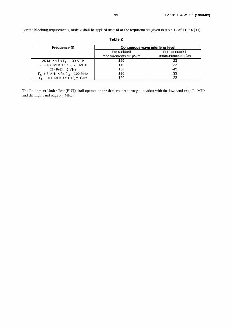
For the blocking requirements, table 2 shall be applied instead of the requirements given in table 12 of TBR 6 [11].
Table 2
Frequency (f) Continuous wave interferer levelFor radiated
measurements dB µV/mFor conducted
measurements dBm
25 MHz ≤ f < FL - 100 MHz 120 -23FL - 100 MHz ≤ f < FL - 5 MHz 110 -33
f - FC > 6 MHz 100 -43FU + 5 MHz < f ≤ FU + 100 MHz 110 -33FU + 100 MHz < f ≤ 12,75 GHz 120 -23
The Equipment Under Test (EUT) shall operate on the declared frequency allocation with the low band edge FL MHzand the high band edge FU MHz.
TR 101 159 V1.1.1 (1998-02)12
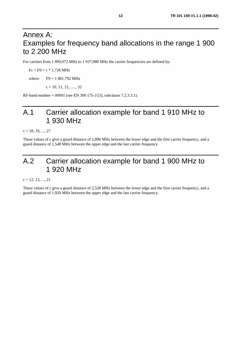
Annex A:Examples for frequency band allocations in the range 1 900to 2 200 MHzFor carriers from 1 899,072 MHz to 1 937,088 MHz the carrier frequencies are defined by:
Fc = F9 + c * 1,728 MHz
where: F9 = 1 881,792 MHz
c = 10, 11, 12, ....., 32
RF-band number = 00001 (see EN 300 175-3 [3], subclause 7.2.3.3.1).
A.1 Carrier allocation example for band 1 910 MHz to1 930 MHz
c = 18, 19, ..., 27
These values of c give a guard distance of 2,896 MHz between the lower edge and the first carrier frequency, and aguard distance of 1,548 MHz between the upper edge and the last carrier frequency.
A.2 Carrier allocation example for band 1 900 MHz to1 920 MHz
c = 12, 13, ..., 21
These values of c give a guard distance of 2,528 MHz between the lower edge and the first carrier frequency, and aguard distance of 1,920 MHz between the upper edge and the last carrier frequency.

TR 101 159 V1.1.1 (1998-02)13
Annex B:Examples of frequency band allocations in within 2 200 MHzto 105 GHz
B.1 Radio frequency bands for Fixed Wireless Access(FWA) applications in the range 2 200 MHz to105 GHz
Following the ongoing work within European Radio communications Office (ERO) and the intentions of the draftEuropean table of frequency allocations and utilization, the following general tentative frequency bands, or parts thereof,may be considered, but not limited to, for future FWA applications.
Table B.1
2 200 - 2 483,5 MHz2 483,5 - 2 500 MHz2 500 - 2 520 MHz2 520 - 2 690 MHz3 400 - 4 200 MHz see clause B.25 150 - 5 250 MHz5 250 - 5 300 MHz10,15 - 10,68 GHz17,10 - 17,70 GHz24,25 - 26,5 GHz27,6 - 29,5 GHz31,8 - 33,4 GHz37,0 - 39,5 GHz40,0 - 43,5 GHz47,2 - 50,2 GHz50,4 - 51,4 GHz59,0 - 63 GHz74,0 - 75,5 GHz84,0 - 86,0 GHz
The regulatory regimes around the world for these bands are traditionally tailored for Frequency Division Duplex (FDD)applications, but Time Division Duplex (TDD) applications are also used. Although most regulators are expected toallow both TDD and FDD systems, it is important to define both TDD and FDD applications of DECT to allow for amost flexible approach to different regulatory regimes.
B.1.1 Definition of access channels, bearersThe different types of DECT bearers are defined in the time domain. Each bearer is also related to a specific carrierfrequency number c and to a specific RF-band number (see EN 300 175-3 [3], subclause 7.2.3.3.1).

TR 101 159 V1.1.1 (1998-02)14
B.1.1.1 TDD
For TDD, the carrier number c relates to a specific carrier frequency Fc used for both the up-link and down-link parts ofa bearer.
5 ms 5 ms 5 ms
Fc d d u u
d indicates down link and u indicates up link. Each d and u field is further divided into 12 time slots.
Figure B.1: TDD frame structure
B.1.1.2 FDD
For FDD a different definition of the carrier number c is required.
Here the carrier number c relates to a specific pair of carrier frequencies Fcu and Fcd. All pairs have the same duplexfrequency separation, fd, given by the regulator, typically 50 - 100 MHz or more. The up-links use carrier Fu and thedown-links carrier Fd. The time relation between up-links and down-links of a bearer is the same as for the TDD case.Thus the same burst mode controllers are used for TDD and FDD. Thus for simplex and duplex beares the down-linksare defined for the first 5 ms of a frame, and the up-links for the last 5 ms, and the time separation between the two partsof a duplex bearer is 5 ms.
B.1.1.3 Definition of Fc, Fd, Fcu and Fcd
The following carrier frequency definitions apply:
Fc = Fg + c * 1,728 MHz,
where c = 10, 11, 12, ....., 32
and Fg is a nominal DECT carrier frequency (see TBR 6 [11], subclause 7.1).
Each specific RF-band number shall have Fg defined, and also Fd if FDD operation shall be applied.
Fcd = Fc and Fcu = Fc - Fd. Fd can be a positive or a negative number.
B.1.2 Dynamic Channel Selection (DCS) algorithmsFDD operation does not require any changes to the DECT DCS algorithms. The DCS algorithms are identical for TDDand FDD. Only the bearer definitions have to be expanded according to subclause B.1.1.
B.1.3 Antenna diversity algorithmsIn stationary and low mobility TDD applications, the fading on up- and down-links are correlated. Therefore it ispossible to use quality information from one direction to influence the antenna selection for the other direction. Such acorrelation does not exist for FDD, whereby it is essential to strictly relate the selection procedure to each linkseparately. This is not a regulatory issue, and it is not complicated.

TR 101 159 V1.1.1 (1998-02)15
B.1.4 Time domain offset for low cost spectrum efficient FDDapplications
Due to combined time and frequency separation for FDD duplex bearers, only half the time domain will be utilized foreach carrier Fcu and Fcd. Thus half of the capacity is unused. The remaining half shall be utilized by having two sets ofbase stations with 5 ms offset between the Global Positioning System (GPS) derived time references for the two sets.Thus every second base station shall belong to the same set. This fully avoids the need for expensive duplex filters forsimplex and duplex bearer services (symmetric) in base sites with several RFPs. This gives a complication for handoverbetween base sites, but this is not generally needed for fixed wireless access.
SET 1
SET 2
5 ms 5 ms 5 ms
Fcd
Fcu
Fcd
Fcu
d
u
d
d
u u
u
d
d indicates down-link and u indicates up-link. Blank field indicates unused area in the time domain.
Figure B.2: The base stations of Set 2 have the time reference, offset by 5 ms relative to Set 1
B.1.5 Operator codes, carrier number and RF-band definitionsA globally unique Operators Code has to be obtained from ETSI (see EN 300 175-6 [6]).
Spectrum allocations in this band are normally assigned each to a single operator. Therefore there is no need tostandardize the carrier and band number assignments for these bands.
Each system however needs to define the carrier numbers internally.
RF-band number 31 (see EN 300 175-3 [3], subclause 7.2.3.3.1) shall be used for propitiatory system carrier frequencydefinitions.
ETSI may standardize carrier and band numbers upon local request for interoperability by a regulator.
B.2 FWA in frequency bands in the range3 400 - 4 200 MHz
The frequency bands in the range 3 400 - 4 200 MHz are today in many countries allocated to the Fixed Service (FS)and thereby opened to Point-to-Multipoint (P-MP) FWA applications. The utilization in the bands are often subject tosharing on a co-primary basis with other services, such as the terrestrial FS and the Fixed Satellite Service (FSS) spaceto Earth. Accordingly the frequency arrangement will be account of in detail.

TR 101 159 V1.1.1 (1998-02)16
B.2.1 Duplex regimesThe available duplex regimes used in two way digital communications applications are considered:
- the widely used paired frequency band regime, where two transmission links, the up and down links, of oneduplex channel operate on two different carriers;
- the often neglected duplex regime normally using an unpaired single frequency band regime, where onetransmission link of one channel operates on the same carrier frequency spatially divided.
Where a frequency duplex assignment is required, the spacing between the lower edges of the paired sub-bands may be50 MHz or 100 MHz, or any other applicable duplex spacing may be used.
Where a time duplex assignment is required an applicable unpaired sub-band may be used.
B.2.2 The regulatory environmentThe current standards and regulations in the frequency bands in the range 3 400 - 4 200 MHz are vague in some areasand too detailed in others. Accordingly some important issues for FWA applications to impact are:
- the possibility to use frequency blocks of appropriate size, instead of pre defined sub-bands, adapted to a certainbandwidth in a given frequency channel arrangement;
- standards and regulations that offer the free choice of duplex regime, to users and operators;
- basically limit generic requirements to output power, out of assigned band emissions, and antenna gain.Modulation type, bit rates, transparency requirements and other and other interoperability related parameters donot belong to the generic regulatory requirements. Factors like packet data over the air and DCS are much moreimportant to the customer satisfaction and efficient use of the spectrum, than strict limits on for instance type ofmodulation or receiver sensitivity, which appear in some proposals for regulatory regimes (see annex C). Toostringent or irrelevant regulatory requirements will limit the evolution of services service and economics withinthe deployed spectrum;
- output power may be up to typically 4 W;
- large freedom to apply antenna gain, typically up to 22 dBi and beyond;
- if applying TBR 6 [11] tests a 5 dB adjustment is required in the relation between field strength and power(see TBR 6 [11], subclause 6.1.1);
- the DECT TBR 6 [11] meets with large margin the out of assigned band emission limits normally applied forfixed services in the range 3 400 - 4 200 MHz.
B.2.3 Block allocations arrangement
B.2.3.1 Block allocation arrangement 50 MHz in CITEL countries
In the CITEL countries P-MP systems may be operated in the ranges 3 400 - 3 600 MHz. Where a frequency duplexallocation is required, the spacing between the lower edges of the paired sub-bands may be 50 MHz. The edges of eachsub-band are specified as follows:
3 400 MHz - 3 600 MHz
Block A,C
Lower sub-band: 3 400 - 3 425 MHzUpper sub-band: 3 450 - 3 475 MHz

TR 101 159 V1.1.1 (1998-02)17
Block B,D
Lower sub-band 3 425 - 3 450 MHzUpper sub-band 3 475 - 3 500 MHz
Block E,G
Lower sub-band: 3 500 - 3 525 MHzUpper sub-band: 3 550 - 3 575 MHz
Block F,H
Lower sub-band: 3 525 - 3 550 MHzUpper sub-band: 3 575 - 3 600 MHz
B.2.3.2 Block allocation arrangement 100 MHz in CITEL countries
In the CITEL countries, P-MP systems may be operated in the ranges 3 400 - 3 500 MHz and 3 500 - 3 600 MHz.Where a frequency duplex allocation is required, the spacing between the lower edges of the paired sub-bands may be100 MHz. The edges of each sub-band are specified as follows:
3 400 MHz - 3 600 MHz
Block A, E
Lower sub-band: 3 400 - 3 425 MHzUpper sub-band: 3 500 - 3 525 MHz
Block B, F
Lower sub-band 3 425 - 3 450 MHzUpper sub-band 3 525 - 3 550 MHz
Block C, G
Lower sub-band: 3 450 - 3 475 MHzUpper sub-band: 3 550 - 3 575 MHz
Block D, H
Lower sub-band: 3 475 - 3 500 MHzUpper sub-band: 3 575 - 3 600 MHz

TR 101 159 V1.1.1 (1998-02)18
B.2.3.3 Block allocation arrangements recommended in the CEPT countries
Where a block assignments are required, a block may be defined as follows:
Block allocation arrangement 50 MHz in CEPT countries
In the CEPT countries, P-MP systems may be operated in the ranges 3 410 - 3 500 MHz and 3 500 - 3 600 MHz. Wherea frequency duplex allocation is required, the spacing between the lower edges of the paired sub-bands may be 50 MHz.The edges of each sub-band are defined as follows:
3 410 MHz - 3 500 MHz
Lower sub-band: 0,25 N + 3 410to0,25 (N + k) + 3 410
MHz
MHzUpper sub-band: 0,25 (N + 200) + 3 410
to0,25 (N + k + 200) + 3 410
MHz
MHz1 ≤ k ≤ 160; 0 ≤ N ≤ 159; k + N ≤ 160
3 500 MHz - 3 600 MHz
Lower sub-band 0,25 N + 3 410to0,25 (N + k) + 3 410
MHz
MHzUpper sub-band 0,25 (N + 200) + 3 410
to0,25 (N + k + 200) + 3 410
MHz
MHz1 ≤ k ≤ 200; 360 ≤ N ≤ 559; k + N – 360 ≤ 200
In the tables above, k defines the width of each sub-band and N defines the lower edge of each sub-band.
P-MP equipment may be used having a frequency duplex spacing other than exactly 50 MHz. However, such equipmentmay conform to the limits of the sub-band allocation as defined above.
Block allocation arrangement 100 MHz
Where a frequency duplex allocation is required, the spacing between the lower edges of each paired sub-band shall be100 MHz. The edges of each sub-band are defined as follows:
Lower sub-band 0,25 N + 3 410to0,25 (N + k) + 3 410
MHz
MHzUpper sub-band 0,25 (N + 400) + 3 410
to0,25 (N + k + 400) + 3 410
MHz
MHz1 ≤ k ≤ 360; 0 ≤ N ≤ 359; k + N ≤ 360
In the table above, k defines the width of each sub-band and N defines the lower edge of each sub-band.
P-MP equipment may be used having a duplex spacing other than exactly 100 MHz. However, such equipment mustconform to the limits of the block allocation as defined above.

TR 101 159 V1.1.1 (1998-02)19
Annex C:Services and spectrum efficiency of DECT Fixed WirelessAccess (FWA) applicationsThe reference model for DECT Radio in the Local Loop (RLL) (FWA) systems is presented in figure C.1.
LE CTA
I /F 1
I /F5a
O A & M
I/F6
TE
WRS
FP
PP TE
I/F5b
I/F4(G A P +da ta)
I/F4(R A P )
I/F4(R A P )
I/F4(G A P + da ta )
I/F4(W R S )
TE: Terminal Equipment.FP: Fixed Part.WRS: Wireless Relay Station.CTA: Cordless Terminal Adapter.PP: Portable Part.
I/F1: Local exchange to FP Interface.I/F4: DECT air Interface.I/F5a: CTA to terminal Interface.I/F5b: PP to terminal Interface.I/F6: OA&M Interface.
Figure C.1: DECT RLL (FWA) reference model
Depending on whether the end-user uses a CTA or a PP, the IF/4 interface can be either RLL Access Profile (RAP) orGAP-compliant. The services facilities and configurations (see ETR 308 [18]) focuses on RAP and describes theservices available at IF/1 that are expected to be provided at IF/5a. The OA&M facilities defined in RAP are only theones that require information to be transported over the RAP air interface.
The DECT RAP standard, ETS 300 765, is divided into two parts:
a) Part 1 [15] "Basic telephony services", which includes Plain Old Telephone Service (POTS) services(unprotected 32 kbit/s ADPCM), a (protected) 64 kbit/s PCM bearer service and over-the-air OA&M services;
b) Part 2 [16] "Advanced telephony services" specifies 2B+D ISDN services (possible 30B + D in the future) and adata port for broadband (up to 552 kbit/s) packet data services.
The new DECT modulation options (on Public Enquiry spring 1998) will enable:
- 2 and 3 times higher user data rate on a standard time slot;
- 7 - 10 dB higher sensitivity (including coherent demodulation);
- uncritical Near Line Of Sight (NLOS) installation by coherent equalizer option;
- 15 km ranges;
- meets Universal Mobile Telecommunications System (UMTS) service requirements for short range mobilesystems and for fixed access;
- Wireless Local Loop (WLL) services competitive with any third generation technology.
It should be noted that effective radio ranges achieved in the DECT RLL application using CTAs, will be considerablygreater than when DECT is used in the mobile mode. The signal path is more consistent, it is often line-of- sight andbase stations and CTAs may use high gain antennas, whose directionality also reduce multipath signals.
DECT provides high capacity FWA services with typically 40 - 100 E average traffic per DECT Access Site (DAS), in a20 MHz allocation. The DAS highly sectorized and are deployed in cellular pattern. 10 - 22 dBi antennas are used.

TR 101 159 V1.1.1 (1998-02)20
For low traffic density scenarios, the capacity is not an issue, but the range is. High gain directive antennas and WRSsare often applied in order to increase the range of the links. The service and facilities description for DECT RLLrequires a range up to 5 km for a DECT radio link. A Line Of Sight (LOS) range of up to 5 km is feasible with 12 dBiantennas at each end and reasonable antenna heights. Thus adding a WRS, will provide a 10 km range.
The DECT standard advance timing of the CTAs up to 17 km range with maintained TDD guard space. LOS ranges of10 - 15 km are thus to a CTA or to a pool of WRSs in a remote village. This however requires high antenna gain (largerantennas) and higher antenna installation.
The DECT ISDN service monitors the ISDN layer 3 information, and allocates DECT bearer resources only when andas required by the specific instant ISDN services. The ISDN speech service has the same spectrum efficiency as thePOTS speech service, and transmitting a specific amount of data (e.g. a document) via ISDN is much more spectrumefficient and loads in average the radio devices less than via POTS (modem). For packet data, transmission over theData Port is much more spectrum efficient and loads in average the radio devices much less than any modem service orISDN service.
By adding a 2 GHz to 3,5 GHz, 10,4 GHz or 18 GHz simple converter at the DECT radio antenna connector, part of theDECT links will provide P-MP services. This can be used to provide a link to a pool of WRS in a remote village. It willalso be very efficient for concentrated high traffic transfer to residential block houses and (medium sized and larger)offices, where not range, but capacity is the main requirement.
It is also possible to deploy the whole DECT FWA within a band in 2 200 MHz - 105 GHz.
DECT FWA is spectrum efficient and very suitable for POTS services, general ISDN services and Internet andother packet data services in residential and office applications.
DECT offers a unique platform for future multimedia and fixed/mobile integration services.

TR 101 159 V1.1.1 (1998-02)21
History
Document history
V1.1.1 February 1998 Publication
ISBN 2-7437-2026-3Dépôt légal : Février 1998