trade of vehicle body repair
TRANSCRIPT
TRADE OF
VEHICLE BODY REPAIR
PHASE 2
Module 3
UNIT: 2
Vehicle Measuring

Produced by
In cooperation with subject matter expert:
Maurice Stack
Some material courtesy of CDX Global and FENC – Further Education National Consortium.
© SOLAS 2014
Table of Contents
Introduction ....................................................................................................................... 1
Unit Objective ................................................................................................................... 2 Vehicle Measuring .......................................................................................................... 2
1.0 Methods of Measuring ............................................................................................. 3
1.1 Vehicle Cross Members and Sub Frames ............................................................ 3
1.2 Datum Points on under Carriage .......................................................................... 3
1.3 Measuring System Principles .................................................................................. 6
1.4 Measuring System Principles .................................................................................. 8
2.0 Selecting Appropriate Gauges ............................................................................... 9
2.1 Gun Sight Gauge Method of Checking Underbody Alignment ...................... 9
2.2 Measuring System Principles ................................................................................ 11
3.0 Trammal Gauge ....................................................................................................... 12 4.0 Applying Measuring System in Accordance with Vehicle Data Sheet ... 13
4.1 Information on Data Sheet .................................................................................. 13
4.2 Data Sheets for Year/Model and Engine In/Out ............................................ 15
4.3 Data Sheets for Year/Model ................................................................................ 16
5.0 Upper Body Measurements ................................................................................. 20
5.1 McPherson Strut Measuring Systems ................................................................. 22
5.2 Measuring System Principles ................................................................................ 24
5.3 The Universal Measuring System (UMS) Mechanical Measuring .................. 26
5.4 The Caroliner Measuring System......................................................................... 27
6.0 Car-O-Liner “Car-O-Tronic” Computerised .................................................. 35
6.1 Computerized Measuring System Principles ..................................................... 38
7.0 Engine Frames and their Possible Hindrance to Repair Rectifications 40
7.1 Hazards Involved in the Removal of Engine Frames ...................................... 40
7.2 Vehicle Structures .................................................................................................. 41
8.0 The Effect of Damage on a Vehicle .................................................................. 43
8.1 The Effect of a Damaged Frame on Steering Geometry ................................ 44
8.2 Steering Systems ..................................................................................................... 45
8.3 Camber, Castor and Swivel-axis Inclination ...................................................... 51
8.4 Steering Components ............................................................................................ 59
Summary ........................................................................................................................... 72 Self-Assessment .............................................................................................................. 73 Suggested Exercise s Damage Analysis Form Training Resources
Table of Figures
Figure 1: Manufacturer’s Transverse Alignment Points ............................................... 4
Figure 2: Manufacturer’s alignment point: vertical and longitudinal ...................... 5
Figure 3: Drop-Line Method of Checking under Body Alignment ........................... 7
Figure 4: The Drop-line Method of Checking Underbody Alignment ..................... 8
Figure 5: Gun Sight Gauge .............................................................................................. 10
Figure 6: Frame Gauges Showing Distortion .............................................................. 10
Figure 7: Body Alignment- Upper Structure ................................................................ 20
Figure 8: Front Diagonal Alignment Check ................................................................. 21
Figure 9: Side Body Check .............................................................................................. 22
Figure 10: McPherson Strut System .............................................................................. 22
Figure 11: Upper Body Measuring System ................................................................... 23
Figure 12: Symmetry Check (Cross Measuring) .......................................................... 24
Figure 13: Measurement of Wheels ............................................................................... 25
Figure 14: Adaptors .......................................................................................................... 27
Figure 15: Measuring System .......................................................................................... 28
Figure 16: Measuring Bridge ........................................................................................... 29
Figure 17: Measuring Slides ............................................................................................. 29
Figure 18: Measuring Devices ......................................................................................... 30
Figure 19: Measuring Device .......................................................................................... 30
Figure 20: Support for Measuring Bridge ..................................................................... 32
Figure 21: Locking Width Dimension ........................................................................... 32
Figure 22: Measuring Slide .............................................................................................. 32
Figure 23: Stud Sleeve ...................................................................................................... 33
Figure 24: Adapter and Stud ........................................................................................... 33
Figure 25: Measuring System .......................................................................................... 33
Figure 26: Overhead View of Measuring System ........................................................ 33
Figure 27: Method 1. ........................................................................................................ 34
Figure 28: Method 2 ......................................................................................................... 34
Figure 29: Measuring System on a Variety of Benches .............................................. 36
Figure 30: TOUCH electronic measurement system CE approved ........................ 39
Figure 31: Separate Engine Frames ............................................................................... 40
Figure 32: Separate Chassis and Body ........................................................................... 41
Figure 33: Chassis ............................................................................................................. 41
Figure 34: Monocoque (mono) Construction .............................................................. 42
Figure 35: Statistics on Angles of Damage Impact ..................................................... 43
Figure 36: Impact Energy Distribution ......................................................................... 44
Figure 37: Steering Layout - Car ..................................................................................... 44
Figure 38,Figure 39 ........................................................................................................... 46
Figure 40: Ackermann Layout ........................................................................................ 46
Figure 41: Ackermann Layout ........................................................................................ 47
Figure 42: Slip Angle ........................................................................................................ 48
Figure 43: Oversteer and Understeer ............................................................................ 49
Figure 44: Vertical Wheel and King Pin Arrangement ............................................... 51
Figure 45: Suspension Systems ....................................................................................... 52
Figure 46: Swivel Axis Inclination ................................................................................. 52
Figure 47: Dished Wheels ................................................................................................ 53
Figure 48: Positive Offset ................................................................................................ 54
Figure 49: Negative Offset .............................................................................................. 55
Figure 50: Castor ............................................................................................................... 56
Figure 51: Wheel Alignment ........................................................................................... 58
Figure 52: Worm and Sector ........................................................................................... 60
Figure 53: Screw and Nut ................................................................................................ 61
Figure 54: Recirculating Ball ........................................................................................... 61
Figure 55: Cam and Peg ................................................................................................... 62
Figure 56: Worm and Roller ........................................................................................... 62
Figure 57: Rack and Pinion ............................................................................................. 63
Figure 58: Steering Joint .................................................................................................. 63
Figure 59: Front Hub – Taper Roller Type .................................................................. 64
Figure 60: Front Hub – Ball-bearing ............................................................................. 64
Figure 61: Front Hub ....................................................................................................... 65
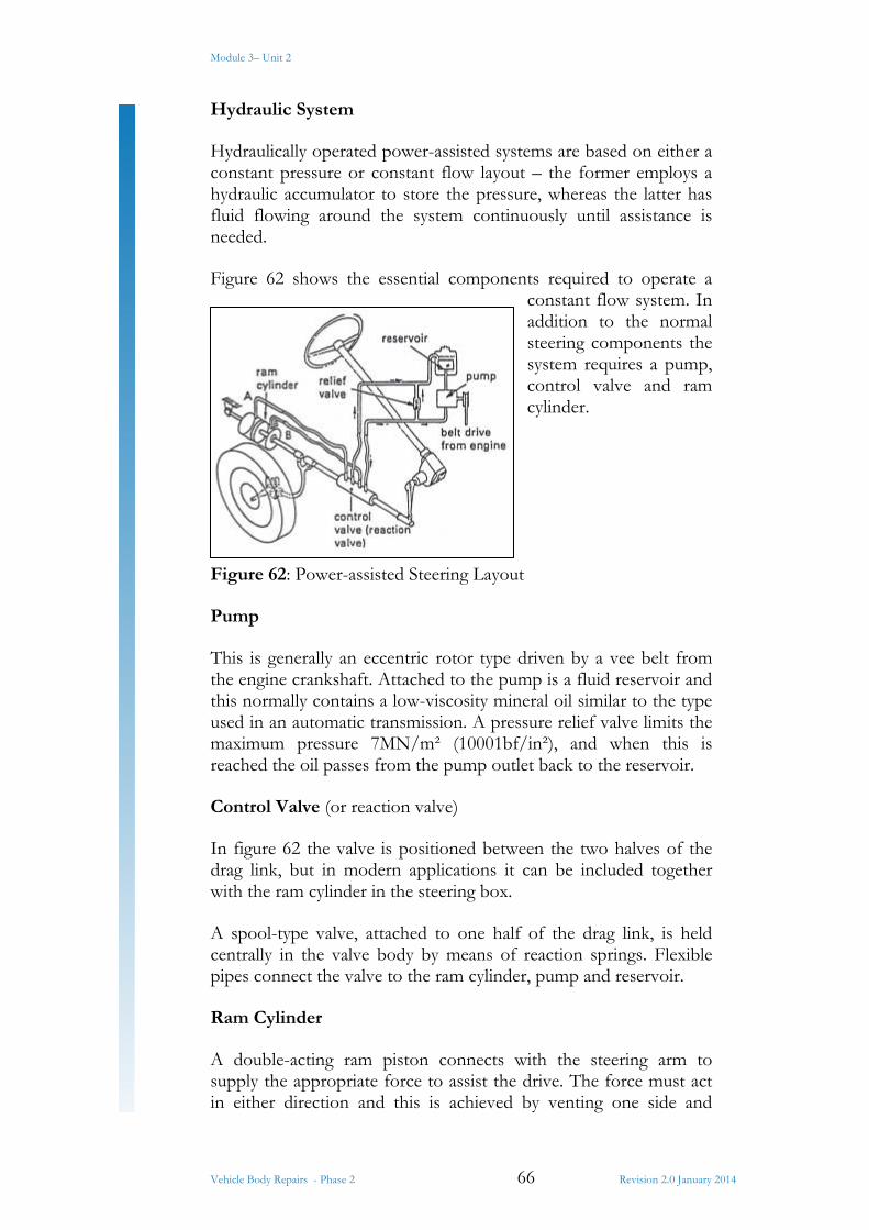
Figure 62: Power-assisted Steering Layout ................................................................... 66
Figure 63: Principle of the Control Valve ..................................................................... 67
Figure 64: Power-assisted Steering Layout ................................................................... 68
Figure 65: Spool Control Valve ...................................................................................... 69
Module 3– Unit 2
Vehicle Body Repairs - Phase 2 1 Revision 2.0 January 2014
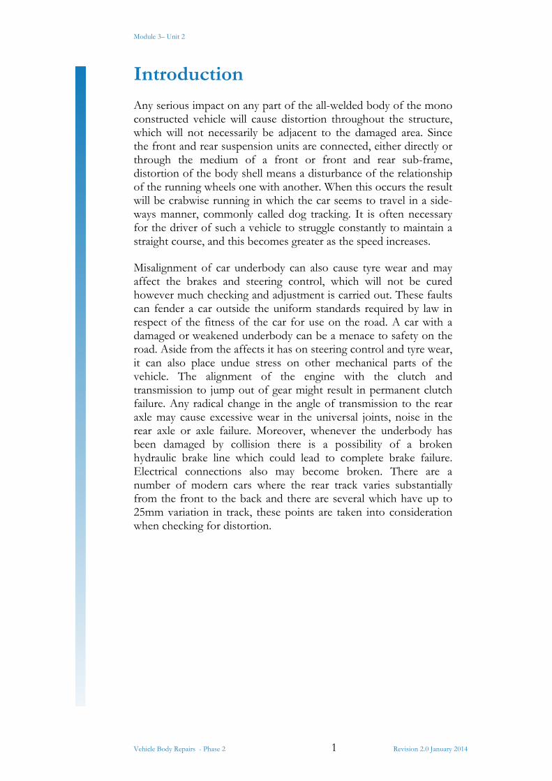
Introduction
Any serious impact on any part of the all-welded body of the mono constructed vehicle will cause distortion throughout the structure, which will not necessarily be adjacent to the damaged area. Since the front and rear suspension units are connected, either directly or through the medium of a front or front and rear sub-frame, distortion of the body shell means a disturbance of the relationship of the running wheels one with another. When this occurs the result will be crabwise running in which the car seems to travel in a side-ways manner, commonly called dog tracking. It is often necessary for the driver of such a vehicle to struggle constantly to maintain a straight course, and this becomes greater as the speed increases.
Misalignment of car underbody can also cause tyre wear and may affect the brakes and steering control, which will not be cured however much checking and adjustment is carried out. These faults can fender a car outside the uniform standards required by law in respect of the fitness of the car for use on the road. A car with a damaged or weakened underbody can be a menace to safety on the road. Aside from the affects it has on steering control and tyre wear, it can also place undue stress on other mechanical parts of the vehicle. The alignment of the engine with the clutch and transmission to jump out of gear might result in permanent clutch failure. Any radical change in the angle of transmission to the rear axle may cause excessive wear in the universal joints, noise in the rear axle or axle failure. Moreover, whenever the underbody has been damaged by collision there is a possibility of a broken hydraulic brake line which could lead to complete brake failure. Electrical connections also may become broken. There are a number of modern cars where the rear track varies substantially from the front to the back and there are several which have up to 25mm variation in track, these points are taken into consideration when checking for distortion.
Module 3– Unit 2
Vehicle Body Repairs - Phase 2 2 Revision 2.0 January 2014
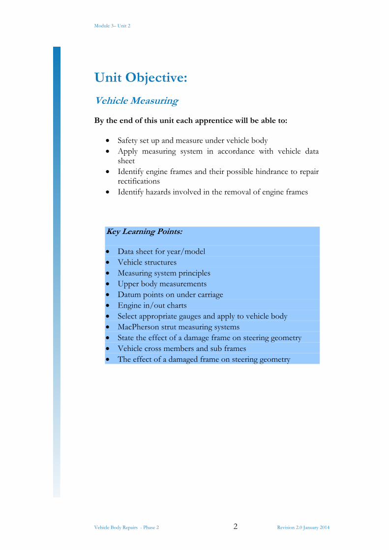
Unit Objective:
Vehicle Measuring
By the end of this unit each apprentice will be able to:
Safety set up and measure under vehicle body Apply measuring system in accordance with vehicle data
sheet Identify engine frames and their possible hindrance to repair
rectifications Identify hazards involved in the removal of engine frames
Key Learning Points:
Data sheet for year/model Vehicle structures Measuring system principles Upper body measurements Datum points on under carriage Engine in/out charts Select appropriate gauges and apply to vehicle body MacPherson strut measuring systems State the effect of a damage frame on steering geometry Vehicle cross members and sub frames The effect of a damaged frame on steering geometry

Module 3– Unit 2
Vehicle Body Repairs - Phase 2 3 Revision 2.0 January 2014
1.0 Methods of Measuring
Checking a mono constructed body shell for underframe alignment
In order to make an alignment check of a mono constructed underbody, the first step is to assess the extent of the damage, the probable amount of force. This information will act as a guide by indicating where to look for possible distortion. With this knowledge a visual check should be made of doors, bonnet, boot lid, roof and centre pillar positions for distortion which may be visible. Inconsistent gaps around these panels show that the panel assembly has been moved during the collision.
The underbody should be checked next. This can only be done by jacking the car up and inserting safety stands, or by using lifting equipment in the form of a hoist which will allow a more thorough examination of the underside of the vehicle.
1.1 Vehicle Cross Members and Sub Frames
The subframes and cross members can be examined for kinks or buckles with the aid of a portable light, but where sighting is difficult or impossible the members are examined by touch. This is not conclusive evidence of distortion, but will generally be sufficient to convince the repairer whether a more precise check should be made by using the dropline method, the gun-sight gauge method, or a jig alignment system.
1.2 Datum Points on under Carriage
To measure a vehicle you will need length, width and height, also known as:
Length - longitudinal Width - transverse Height – Vertical
A datum line is a line that’s horizontal and parallel to a vehicles floor from which heights are taken. A zero point is an undamaged point from which measurements are taken and ensures the system is square before commencing with any other datum points. A centre line is a longitudinal line down the centre of a vehicle from which transverse measurements are taken.
Module 3– Unit 2
Vehicle Body Repairs - Phase 2 4 Revision 2.0 January 2014
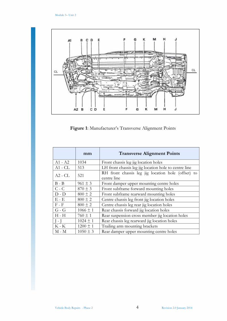
Figure 1: Manufacturer’s Transverse Alignment Points
mm Transverse Alignment Points
A1 - A2 1034 Front chassis leg jig location holes A1 - CL 513 LH front chassis leg jig location hole to centre line
A2 - CL 521 RH front chassis leg jig location hole (offset) to centre line
B - B 961 ± 3 Front damper upper mounting centre holes C - C 870 ± 3 Front subframe forward mounting holes D - D 800 ± 2 Front subframe rearward mounting holes E - E 800 ± 2 Centre chassis leg front jig location holes F - F 800 ± 2 Centre chassis leg rear jig location holes G - G 1066 ± 1 Rear chassis forward jig location holes H - H 760 ± 1 Rear suspension cross member jig location holes J - J 1024 ± 1 Rear chassis leg rearward jig location holes K - K 1200 ± 1 Trailing arm mounting brackets M - M 1050 ± 3 Rear damper upper mounting centre holes

Module 3– Unit 2
Vehicle Body Repairs - Phase 2 5 Revision 2.0 January 2014
Figure 2: Manufacturer’s alignment point: vertical and longitudinal
Line marked X is the Datum Line and must be set up first.
Length mm Alignment Points: Longitudinal
A - D 785 Front chassis leg forward jig locating hole to subframe rear locating hole.
B - D 294 ± 3 Front damper upper mounting hole to subframe rear mounting hole
C - D 184 ± 3 Front subframe forward mounting hole to rear mounting hole
D - E 280 ± 2 Front subfame rear mounting hole to centre chassis leg front jig location hole
D -J 3033 Front subframe rear mounting hole to rear chassis leg rearward jig location hole
D - F 1220 ± 3 Front subframe rear mounting hole to rear suspension cross member jig location hole
G - H 827 ± 3 Rear chassis leg forward jig location hole to rear suspension cross member jig location hole
G - J 1363 (Ref) Rear chassis leg front to rear jig location holes K - M 501.5 ± 3 Trailing arm mounting to rear damper upper
mounting centre hole K - H 537 ± 3 Trailing arm mounting to rear damper upper
mounting centre hole H - J 536 ± 3 Rear suspension cross member jig location hole to
rear chassis leg rearward jig location hole
Module 3– Unit 2
Vehicle Body Repairs - Phase 2 6 Revision 2.0 January 2014
1.3 Measuring System Principles
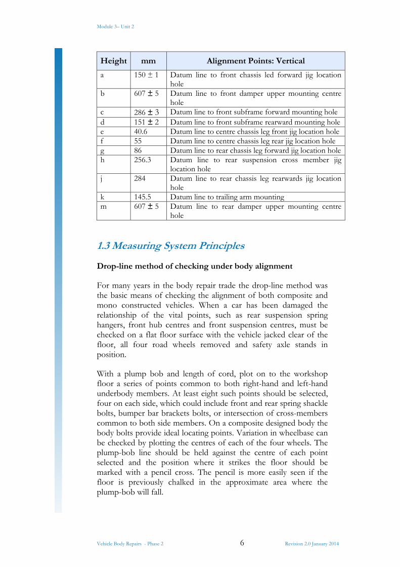
Drop-line method of checking under body alignment
For many years in the body repair trade the drop-line method was the basic means of checking the alignment of both composite and mono constructed vehicles. When a car has been damaged the relationship of the vital points, such as rear suspension spring hangers, front hub centres and front suspension centres, must be checked on a flat floor surface with the vehicle jacked clear of the floor, all four road wheels removed and safety axle stands in position.
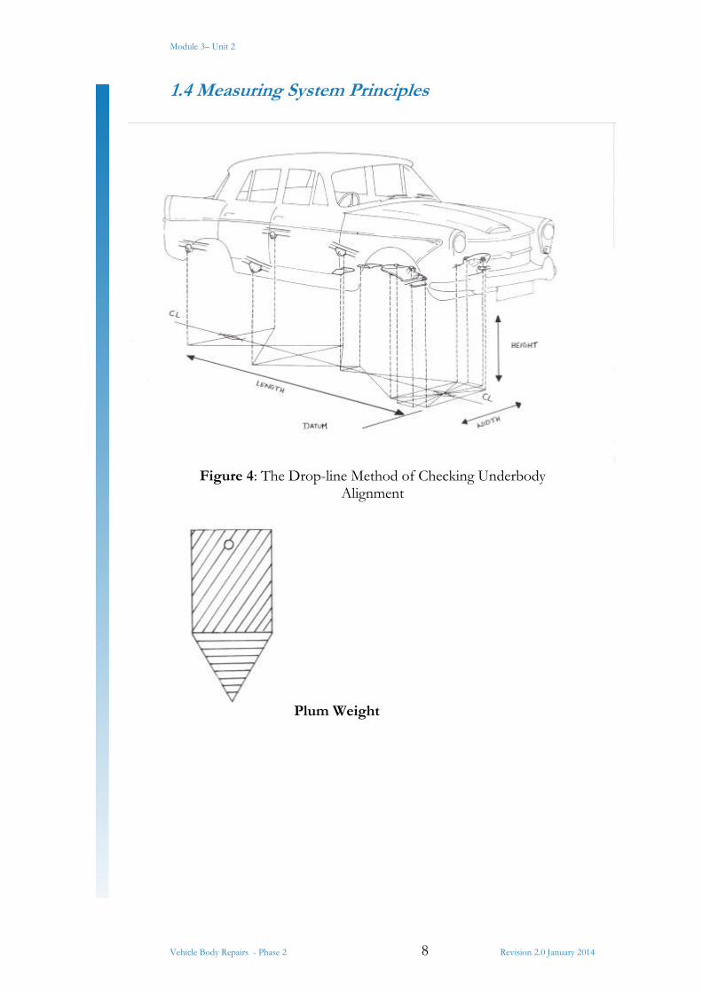
With a plump bob and length of cord, plot on to the workshop floor a series of points common to both right-hand and left-hand underbody members. At least eight such points should be selected, four on each side, which could include front and rear spring shackle bolts, bumper bar brackets bolts, or intersection of cross-members common to both side members. On a composite designed body the body bolts provide ideal locating points. Variation in wheelbase can be checked by plotting the centres of each of the four wheels. The plump-bob line should be held against the centre of each point selected and the position where it strikes the floor should be marked with a pencil cross. The pencil is more easily seen if the floor is previously chalked in the approximate area where the plump-bob will fall.
Height mm Alignment Points: Vertical
a 150 ± 1 Datum line to front chassis led forward jig location hole
b 607 ± 5 Datum line to front damper upper mounting centre hole
c 286 ± 3 Datum line to front subframe forward mounting hole d 151 ± 2 Datum line to front subframe rearward mounting holee 40.6 Datum line to centre chassis leg front jig location hole f 55 Datum line to centre chassis leg rear jig location hole g 86 Datum line to rear chassis leg forward jig location holeh 256.3 Datum line to rear suspension cross member jig
location hole j 284 Datum line to rear chassis leg rearwards jig location
hole k 145.5 Datum line to trailing arm mounting m 607 ± 5 Datum line to rear damper upper mounting centre
hole
Module 3– Unit 2
Vehicle Body Repairs - Phase 2 7 Revision 2.0 January 2014
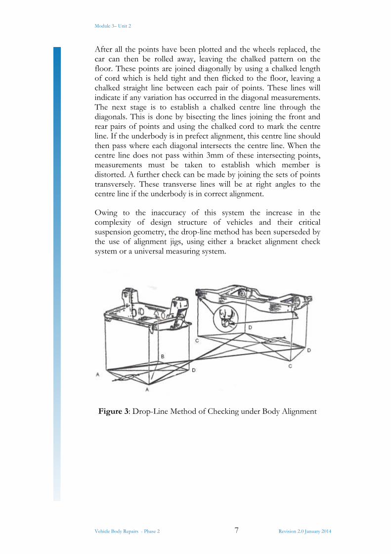
After all the points have been plotted and the wheels replaced, the car can then be rolled away, leaving the chalked pattern on the floor. These points are joined diagonally by using a chalked length of cord which is held tight and then flicked to the floor, leaving a chalked straight line between each pair of points. These lines will indicate if any variation has occurred in the diagonal measurements. The next stage is to establish a chalked centre line through the diagonals. This is done by bisecting the lines joining the front and rear pairs of points and using the chalked cord to mark the centre line. If the underbody is in prefect alignment, this centre line should then pass where each diagonal intersects the centre line. When the centre line does not pass within 3mm of these intersecting points, measurements must be taken to establish which member is distorted. A further check can be made by joining the sets of points transversely. These transverse lines will be at right angles to the centre line if the underbody is in correct alignment.
Owing to the inaccuracy of this system the increase in the complexity of design structure of vehicles and their critical suspension geometry, the drop-line method has been superseded by the use of alignment jigs, using either a bracket alignment check system or a universal measuring system.
Figure 3: Drop-Line Method of Checking under Body Alignment
Module 3– Unit 2
Vehicle Body Repairs - Phase 2 8 Revision 2.0 January 2014
1.4 Measuring System Principles
Figure 4: The Drop-line Method of Checking Underbody Alignment
Plum Weight
Module 3– Unit 2
Vehicle Body Repairs - Phase 2 9 Revision 2.0 January 2014
2.0 Selecting Appropriate Gauges
2.1 Gun Sight Gauge Method of Checking Underbody Alignment
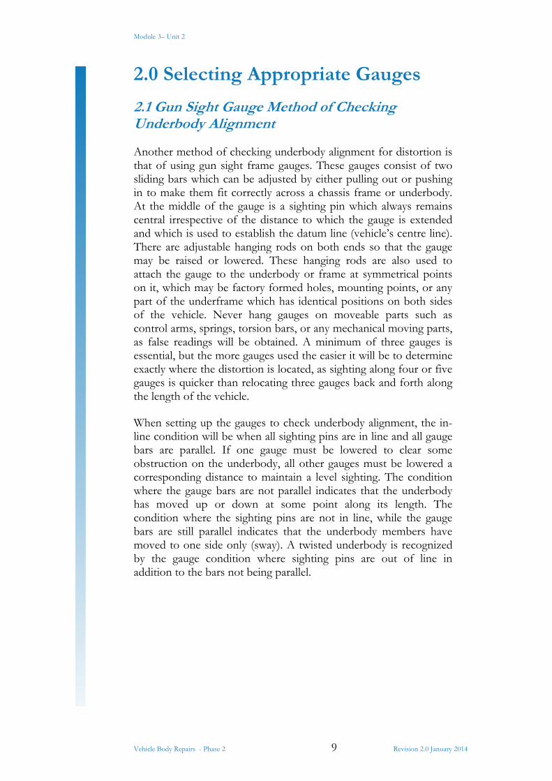
Another method of checking underbody alignment for distortion is that of using gun sight frame gauges. These gauges consist of two sliding bars which can be adjusted by either pulling out or pushing in to make them fit correctly across a chassis frame or underbody. At the middle of the gauge is a sighting pin which always remains central irrespective of the distance to which the gauge is extended and which is used to establish the datum line (vehicle’s centre line). There are adjustable hanging rods on both ends so that the gauge may be raised or lowered. These hanging rods are also used to attach the gauge to the underbody or frame at symmetrical points on it, which may be factory formed holes, mounting points, or any part of the underframe which has identical positions on both sides of the vehicle. Never hang gauges on moveable parts such as control arms, springs, torsion bars, or any mechanical moving parts, as false readings will be obtained. A minimum of three gauges is essential, but the more gauges used the easier it will be to determine exactly where the distortion is located, as sighting along four or five gauges is quicker than relocating three gauges back and forth along the length of the vehicle.
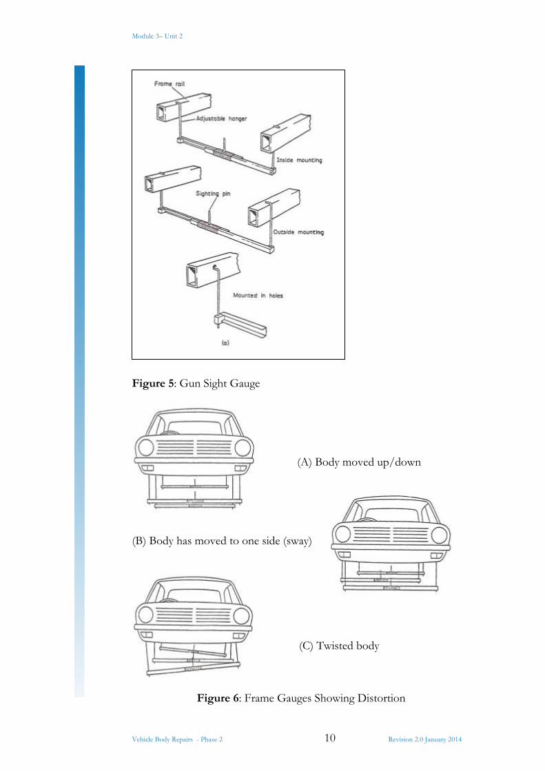
When setting up the gauges to check underbody alignment, the in-line condition will be when all sighting pins are in line and all gauge bars are parallel. If one gauge must be lowered to clear some obstruction on the underbody, all other gauges must be lowered a corresponding distance to maintain a level sighting. The condition where the gauge bars are not parallel indicates that the underbody has moved up or down at some point along its length. The condition where the sighting pins are not in line, while the gauge bars are still parallel indicates that the underbody members have moved to one side only (sway). A twisted underbody is recognized by the gauge condition where sighting pins are out of line in addition to the bars not being parallel.
Module 3– Unit 2
Vehicle Body Repairs - Phase 2 10 Revision 2.0 January 2014
Figure 5: Gun Sight Gauge
(A) Body moved up/down
(B) Body has moved to one side (sway)
(C) Twisted body
Figure 6: Frame Gauges Showing Distortion
Module 3– Unit 2
Vehicle Body Repairs - Phase 2 11 Revision 2.0 January 2014
2.2 Measuring System Principles
Vehicle Alignment Checks using a Digital Measuring Tool
This is a lightweight aluminium measuring tool which can be used to check body alignment on any part of the vehicle body. By extending the tool, its measuring range covers from 2mm up to 3683mm. the measurements are displayed on an LCD digital readout, in either metric (millimeters) or imperial (feet and inches), and are accurate to 1mm. It is supplied with pointers, cones and magnetic bases so that accurate measurements can be taken on various parts of the vehicle without difficulty. This measuring tool is used for comparative measurements when checking a vehicle fro damage and when estimating a repair. While a vehicle is on a jig, the tool can be used to double check measurements taken by the jig’s own measuring system. It also can be used for measuring a vehicles wheelbase and comparing it with manufacturer’s data. In addition it can be used to check the critical suspension points before, during and after repair.

Module 3– Unit 2
Vehicle Body Repairs - Phase 2 12 Revision 2.0 January 2014
3.0 Trammal Gauge
A trammel gauge accurately measures the distance between two fixed points.
Light and easy to handle, the Trammel Gauge remains perfectly aligned even when fully open. It carries out the following operations with maximum precision: Squaring of vehicle wheelbase checks, checking deformations in the door, engine compartments and window frames.

Module 3– Unit 2
Vehicle Body Repairs - Phase 2 13 Revision 2.0 January 2014
4.0 Applying Measuring System in Accordance with Vehicle Data Sheet
4.1 Information on Data Sheet
Manufacturer Data sheet number Data sheet issue Distance of clamps from rear axle centre Side view, left side Position of clamp jaws Special chassis clamps R = right L = left Adaptor type. Height, M234 HMP Measuring point number Height tube, lengths B,C,D, etc. Type of measuring adaptor
Circle = assembled Square = dismantled Vertical dimension Vertical dim. With engine removed Length dim. Right side of vehicle
(for unsymmetrical lengths, right side – left side) Vehicle viewed from above Dim. In brackets = major deviations between vehicles of
same model Width dimension from centre line Vehicle centre line Vertical dimension, left side for non-symmetrical vertical
dimension Length dim. From zero point Explanatory drawings for measuring pts
Circle = assembled square = dismantled Dimensions for M234 HMP Length dimension for M234 HMP R = right L = left
Module 3– Unit 2
Vehicle Body Repairs - Phase 2 14 Revision 2.0 January 2014
Data sheets are available from various sources:
Manufacturers Re-alignment equipment manufacturers Thatchem Auto data
Car-O-Liner Data sheet
The data sheet files contain data sheets and check lists for most car models. The dimensions given must be regarded as guide-lines since dimensions may vary slightly between vehicles of the same model, due to manufacturing tolerances or earlier repair work. The check list is updated and new data sheets are issued at least once per year.
The data sheet shows the height, length and width dimensions at a number of measuring points on the vehicle. The data sheet also gives information on the correct points for placing the chassis clamps and where and how special devices or clamps should be used. If extra equipment is required, this is indicated in the check list.
The upper figure on the data sheet shows the left side of the vehicle, with the position of the chassis clamps expressed as A and B measurements from the centre of the rear axle to the centre of the clamp. The diagrams of the chassis clamps indicate whether the toothed jaw segments are to be attached to the angle of the clamp or to the mounting plate. The figure in the centre of the data sheet shows the vehicle as seen from above
Near the bottom of the page there are explanatory diagrams of the measuring devices that are required.
Module 3– Unit 2
Vehicle Body Repairs - Phase 2 15 Revision 2.0 January 2014
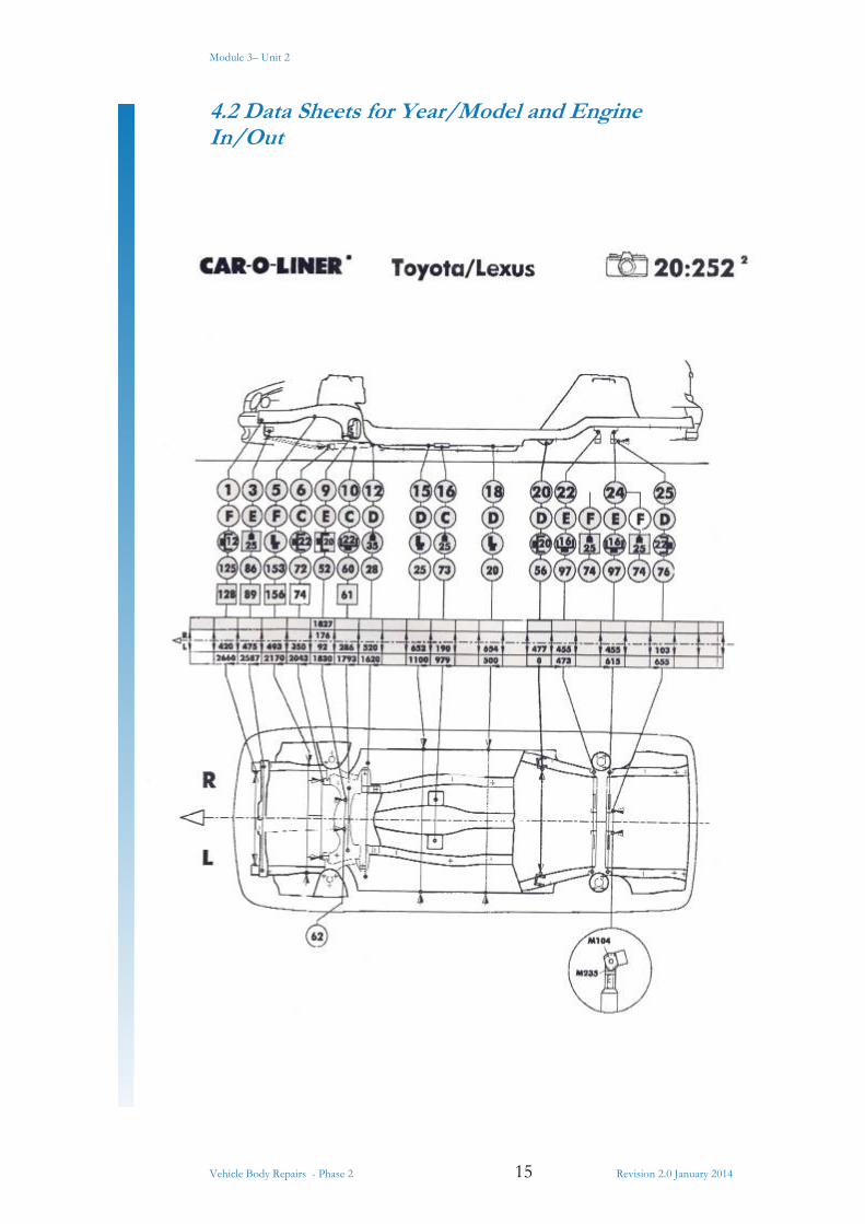
4.2 Data Sheets for Year/Model and Engine In/Out

Module 3– Unit 2
Vehicle Body Repairs - Phase 2 16 Revision 2.0 January 2014
4.3 Data Sheets for Year/Model
Make: Citroen
Model: Xantia - FWD, Sedan, Break, 4-5 Door
Year 1993 – 1999
Measurements taken before repair, the arrow indicates direction of pull.
Module 3– Unit 2
Vehicle Body Repairs - Phase 2 17 Revision 2.0 January 2014
Module 3– Unit 2
Vehicle Body Repairs - Phase 2 18 Revision 2.0 January 2014
Module 3– Unit 2
Vehicle Body Repairs - Phase 2 19 Revision 2.0 January 2014
Module 3– Unit 2
Vehicle Body Repairs - Phase 2 20 Revision 2.0 January 2014
5.0 Upper Body Measurements
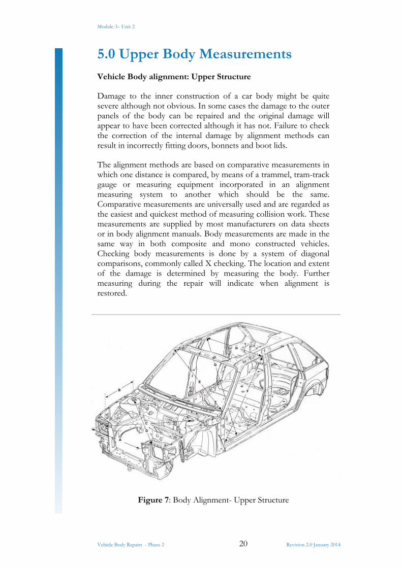
Vehicle Body alignment: Upper Structure
Damage to the inner construction of a car body might be quite severe although not obvious. In some cases the damage to the outer panels of the body can be repaired and the original damage will appear to have been corrected although it has not. Failure to check the correction of the internal damage by alignment methods can result in incorrectly fitting doors, bonnets and boot lids.
The alignment methods are based on comparative measurements in which one distance is compared, by means of a trammel, tram-track gauge or measuring equipment incorporated in an alignment measuring system to another which should be the same. Comparative measurements are universally used and are regarded as the easiest and quickest method of measuring collision work. These measurements are supplied by most manufacturers on data sheets or in body alignment manuals. Body measurements are made in the same way in both composite and mono constructed vehicles. Checking body measurements is done by a system of diagonal comparisons, commonly called X checking. The location and extent of the damage is determined by measuring the body. Further measuring during the repair will indicate when alignment is restored.
Figure 7: Body Alignment- Upper Structure
Module 3– Unit 2
Vehicle Body Repairs - Phase 2 21 Revision 2.0 January 2014
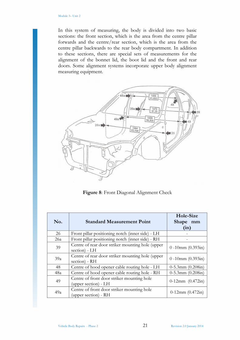
In this system of measuring, the body is divided into two basic sections: the front section, which is the area from the centre pillar forwards and the centre/rear section, which is the area from the centre pillar backwards to the rear body compartment. In addition to these sections, there are special sets of measurements for the alignment of the bonnet lid, the boot lid and the front and rear doors. Some alignment systems incorporate upper body alignment measuring equipment.
Figure 8: Front Diagonal Alignment Check
No. Standard Measurement Point Hole-Size
Shape mm (in)
26 Front pillar positioning notch (inner side) - LH - 26a Front pillar positioning notch (inner side) - RH -
39 Centre of rear door striker mounting hole (upper section) - LH
0 -10mm (0.393in)
39a Centre of rear door striker mounting hole (upper section) - RH 0 -10mm (0.393in)
48 Centre of hood opener cable routing hole - LH 0-5.3mm (0.208in)48a Centre of hood opener cable routing hole - RH 0-5.3mm (0.208in)
49 Centre of front door striker mounting hole (upper section) - LH 0-12mm (0.472in)
49a Centre of front door striker mounting hole (upper section) - RH
0-12mm (0.472in)
Module 3– Unit 2
Vehicle Body Repairs - Phase 2 22 Revision 2.0 January 2014
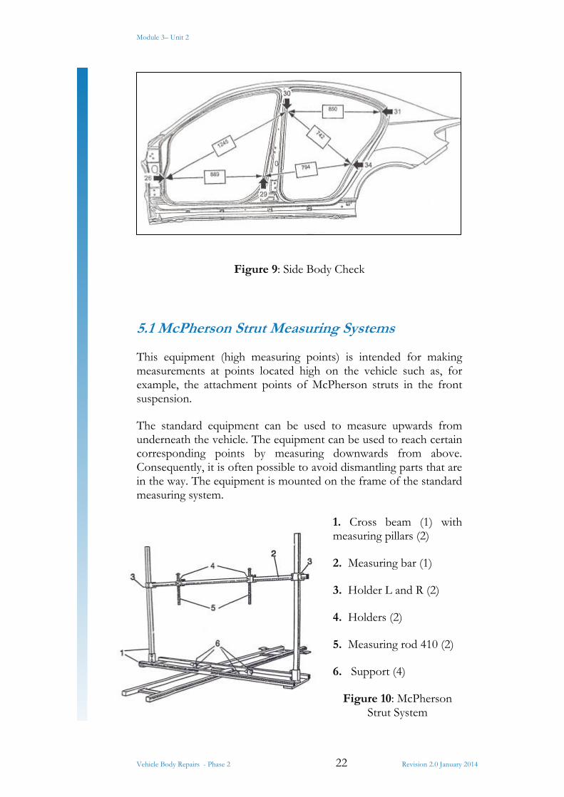
Figure 9: Side Body Check
5.1 McPherson Strut Measuring Systems
This equipment (high measuring points) is intended for making measurements at points located high on the vehicle such as, for example, the attachment points of McPherson struts in the front suspension.
The standard equipment can be used to measure upwards from underneath the vehicle. The equipment can be used to reach certain corresponding points by measuring downwards from above. Consequently, it is often possible to avoid dismantling parts that are in the way. The equipment is mounted on the frame of the standard measuring system.
1. Cross beam (1) with measuring pillars (2)
2. Measuring bar (1)
3. Holder L and R (2)
4. Holders (2)
5. Measuring rod 410 (2)
6. Support (4)
Figure 10: McPherson Strut System

Module 3– Unit 2
Vehicle Body Repairs - Phase 2 23 Revision 2.0 January 2014
This measuring equipment makes it possible to measure the upper anchoring points of McPherson struts, together with symmetry measurements of engine compartment, passenger compartment, etc.
Figure 11: Upper Body Measuring System
Upper body measuring with brackets
Module 3– Unit 2
Vehicle Body Repairs - Phase 2 24 Revision 2.0 January 2014
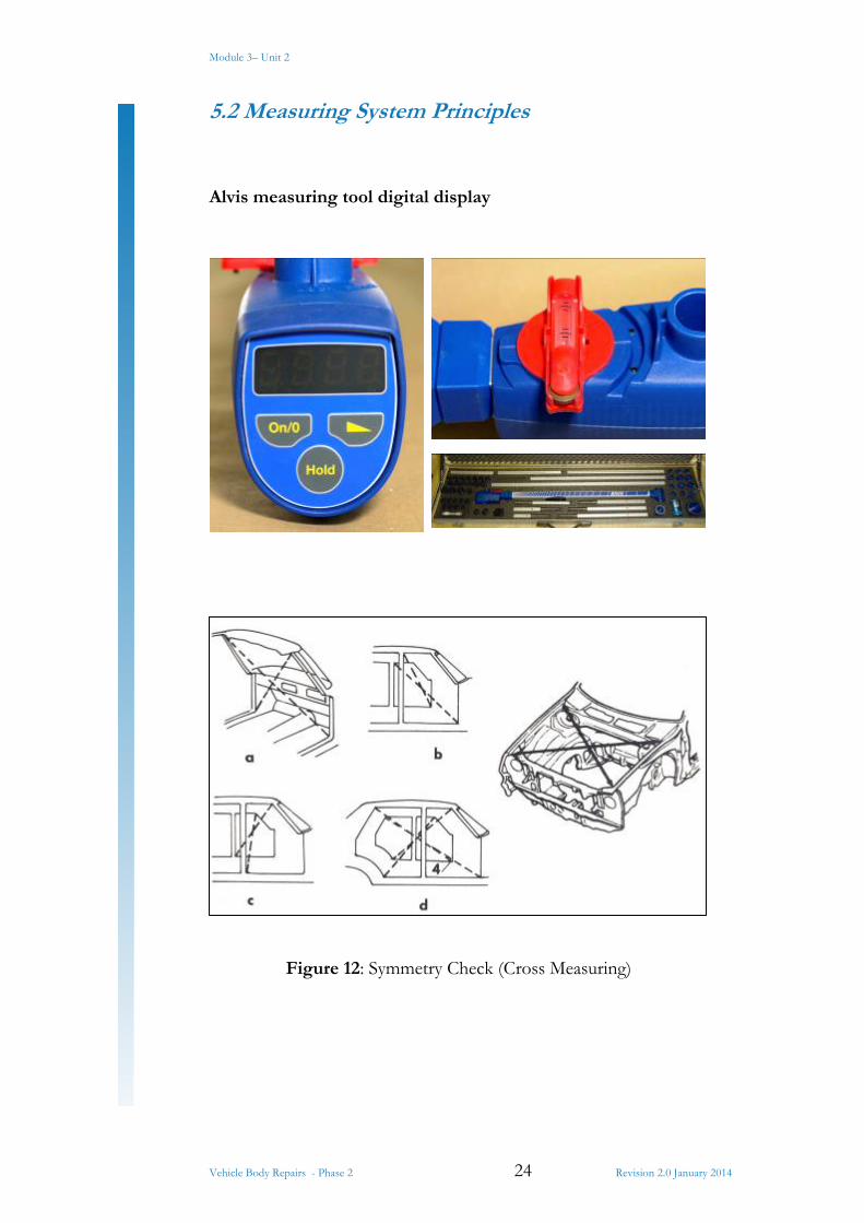
5.2 Measuring System Principles
Alvis measuring tool digital display
Figure 12: Symmetry Check (Cross Measuring)
Module 3– Unit 2
Vehicle Body Repairs - Phase 2 25 Revision 2.0 January 2014
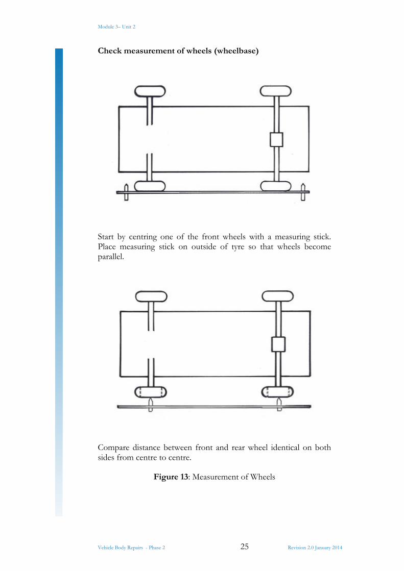
Check measurement of wheels (wheelbase)
Start by centring one of the front wheels with a measuring stick. Place measuring stick on outside of tyre so that wheels become parallel.
Compare distance between front and rear wheel identical on both sides from centre to centre.
Figure 13: Measurement of Wheels
Module 3– Unit 2
Vehicle Body Repairs - Phase 2 26 Revision 2.0 January 2014
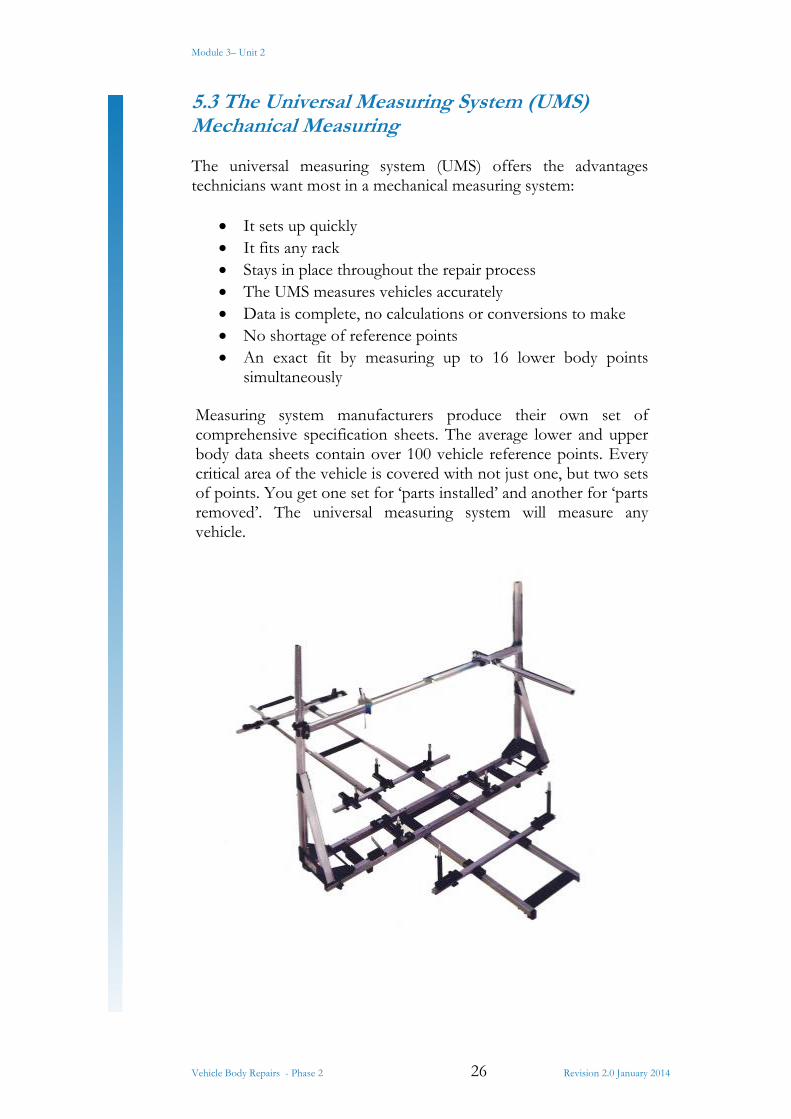
5.3 The Universal Measuring System (UMS) Mechanical Measuring
The universal measuring system (UMS) offers the advantages technicians want most in a mechanical measuring system:
It sets up quickly It fits any rack Stays in place throughout the repair process The UMS measures vehicles accurately Data is complete, no calculations or conversions to make No shortage of reference points An exact fit by measuring up to 16 lower body points
simultaneously
Measuring system manufacturers produce their own set of comprehensive specification sheets. The average lower and upper body data sheets contain over 100 vehicle reference points. Every critical area of the vehicle is covered with not just one, but two sets of points. You get one set for ‘parts installed’ and another for ‘parts removed’. The universal measuring system will measure any vehicle.
Module 3– Unit 2
Vehicle Body Repairs - Phase 2 27 Revision 2.0 January 2014
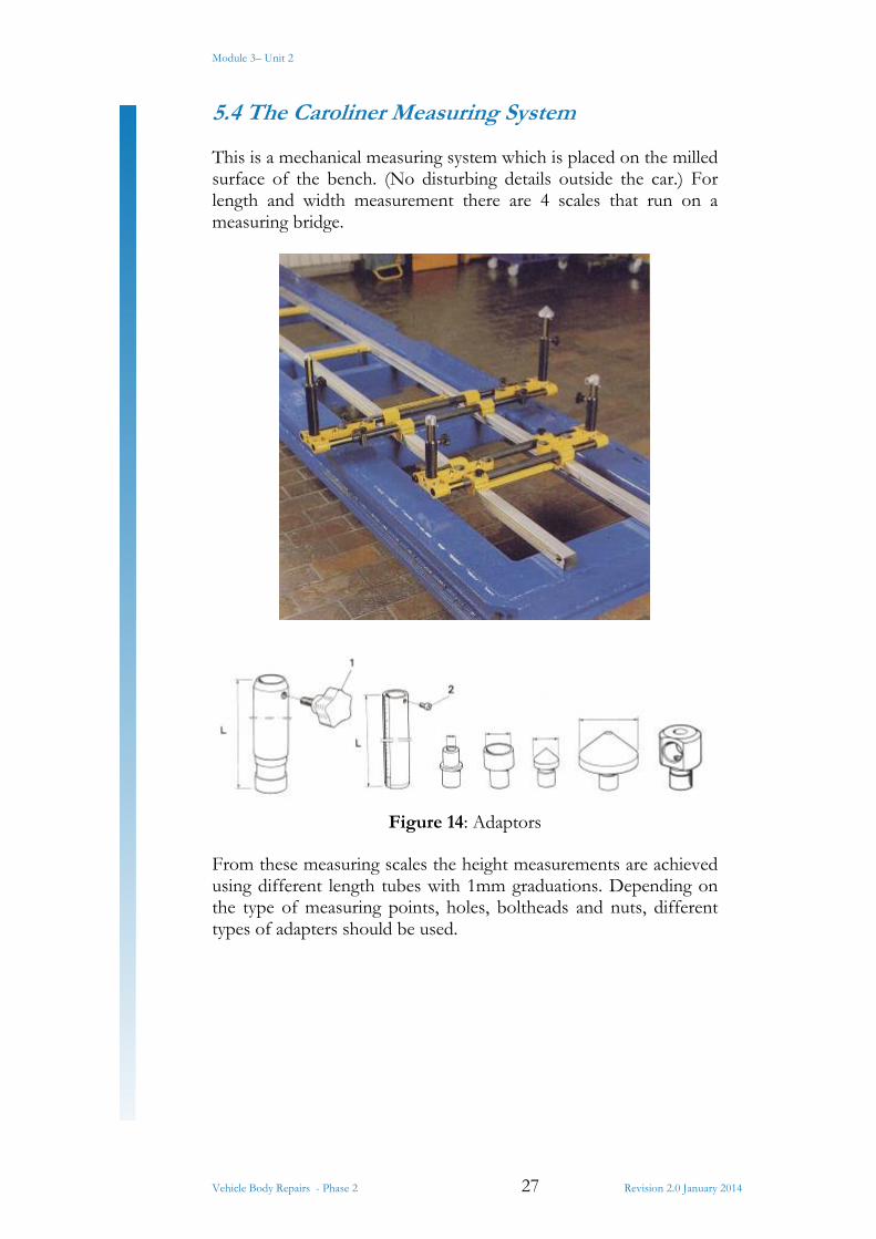
5.4 The Caroliner Measuring System
This is a mechanical measuring system which is placed on the milled surface of the bench. (No disturbing details outside the car.) For length and width measurement there are 4 scales that run on a measuring bridge.
Figure 14: Adaptors
From these measuring scales the height measurements are achieved using different length tubes with 1mm graduations. Depending on the type of measuring points, holes, boltheads and nuts, different types of adapters should be used.
Module 3– Unit 2
Vehicle Body Repairs - Phase 2 28 Revision 2.0 January 2014
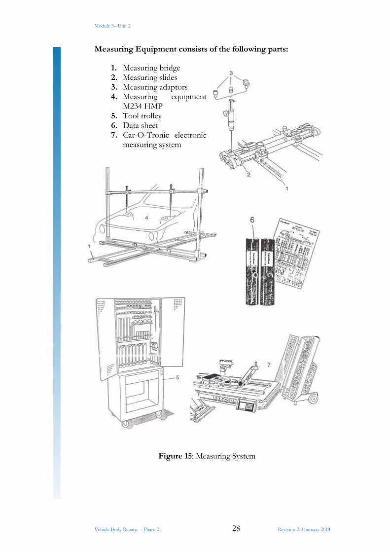
Measuring Equipment consists of the following parts:
1. Measuring bridge 2. Measuring slides 3. Measuring adaptors 4. Measuring equipment
M234 HMP 5. Tool trolley 6. Data sheet 7. Car-O-Tronic electronic
measuring system
Figure 15: Measuring System

Module 3– Unit 2
Vehicle Body Repairs - Phase 2 29 Revision 2.0 January 2014
Measuring Bridge
The measuring bridge is made of aluminium and is provided, on both sides, with moveable measuring tapes for length measurements. It is designed to be placed on the flat milled surface of the frame.
Figure 16: Measuring Bridge
Measuring Slides
The measuring slides run on the measuring bridge, have width measurement scales and are available in two types:
Type 1 for total widths between 500 and 800mm Type 2 for total widths between 800 and 1400mm
There is a pull-out slide on each side. This is provided with three mounting holes for height tubes. The holes are spaced at 100mm. readings are made on scales on the side of the tubes of the slide and on the end plates.
Figure 17: Measuring Slides
Module 3– Unit 2
Vehicle Body Repairs - Phase 2 30 Revision 2.0 January 2014
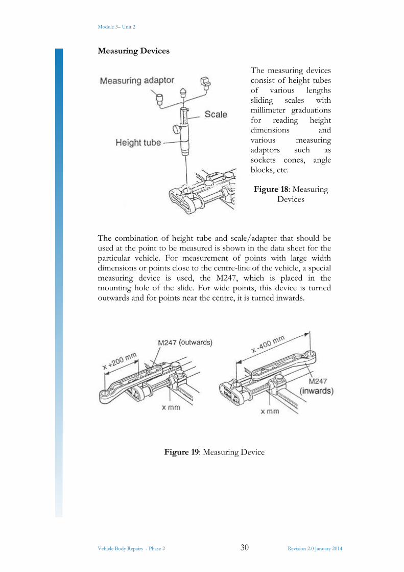
Measuring Devices
The measuring devices consist of height tubes of various lengths sliding scales with millimeter graduations for reading height dimensions and various measuring adaptors such as sockets cones, angle blocks, etc.
Figure 18: Measuring Devices
The combination of height tube and scale/adapter that should be used at the point to be measured is shown in the data sheet for the particular vehicle. For measurement of points with large width dimensions or points close to the centre-line of the vehicle, a special measuring device is used, the M247, which is placed in the mounting hole of the slide. For wide points, this device is turned outwards and for points near the centre, it is turned inwards.
Figure 19: Measuring Device
Module 3– Unit 2
Vehicle Body Repairs - Phase 2 31 Revision 2.0 January 2014
Centring the measuring system for considerable serve side damage:
1. Start your measurements on the undamaged side. Do not take the length dimension into account, since it is nearly always too long when one side of the vehicle has been severely damaged.
2. Select two points, as far apart from each other, on the undamaged side.
3. Set the measuring slides with the width dimension given in the data sheet for the selected measuring point.
4. Fit a stud sleeve, measuring stud and adaptor as indicated in the data sheet. Lock with screw and knob.
5. Find the measurement points on the vehicle and adjust the measuring system to these points.
6. Lock the measuring slides against the measuring bridge. Lock only side only.
The measuring system is now centred. The damage can be evaluated by placing the measuring studs and adapters against the measurement points on the damaged side.
The difference can now be determined, which will provide a good idea of the extent of the damage.
Placing and Centring of the Measuring System
1. Evaluate the damage and look for undamaged measuring points by comparing against data sheet.
2. Select at least three undamaged points for centring the measuring system. These are required to determine the location of the centre line of the vehicle. These points should be as far apart as possible.
3. Place the measuring bridge on the bench, so that the length dimension can be read on the measuring tape. Make sure that the measuring bridge is supported at both ends. Use the measuring bridge support.
4. Select a measuring slide covering the width dimension given in the data sheet. In this example we assume that the 0-points on both sides are undamaged.
5. Set the given dimension on one side of the measuring slide and lock with knob.
6. Place the measuring slide on the measuring bridge under the 0-points. Make sure the measuring tape is on the correct side of the measuring slide. The entire impact angle should be visible when it lies against the slide.
Module 3– Unit 2
Vehicle Body Repairs - Phase 2 32 Revision 2.0 January 2014
7. Take out the height tube specified in the data sheet, e.g. C,D,E, etc.
8. Place the height tube in the outermost hole of the measuring slide and lock with the stop screw.
9. Select a measuring scale which covers the vertical dimensions given in the data sheet; place the measuring scale in the height tube.
10. Place in position the measuring adaptor specified in the data sheet and lock it into position with the stop screw.
11. Raise the measuring stud so that the adapter is in contact with the measurement point. Lock it with the knob. Do not lock it against the scale.
12. Repeat points 7 and 11 on the other side of the measuring slide.
13. Read the width dimension and adjust as necessary, to obtain the same measurements on both sides. The dimensions given in the data sheet should be considered guidelines only.
14. Repeat the procedure as indicated in points 4 to 13 for another measurement point.
15. Lock the measuring slides against the bridge with the stop screw. Lock one side only.
The measuring system is now centred, i.e. the measuring bridge is lined up with the centre line of the vehicle.
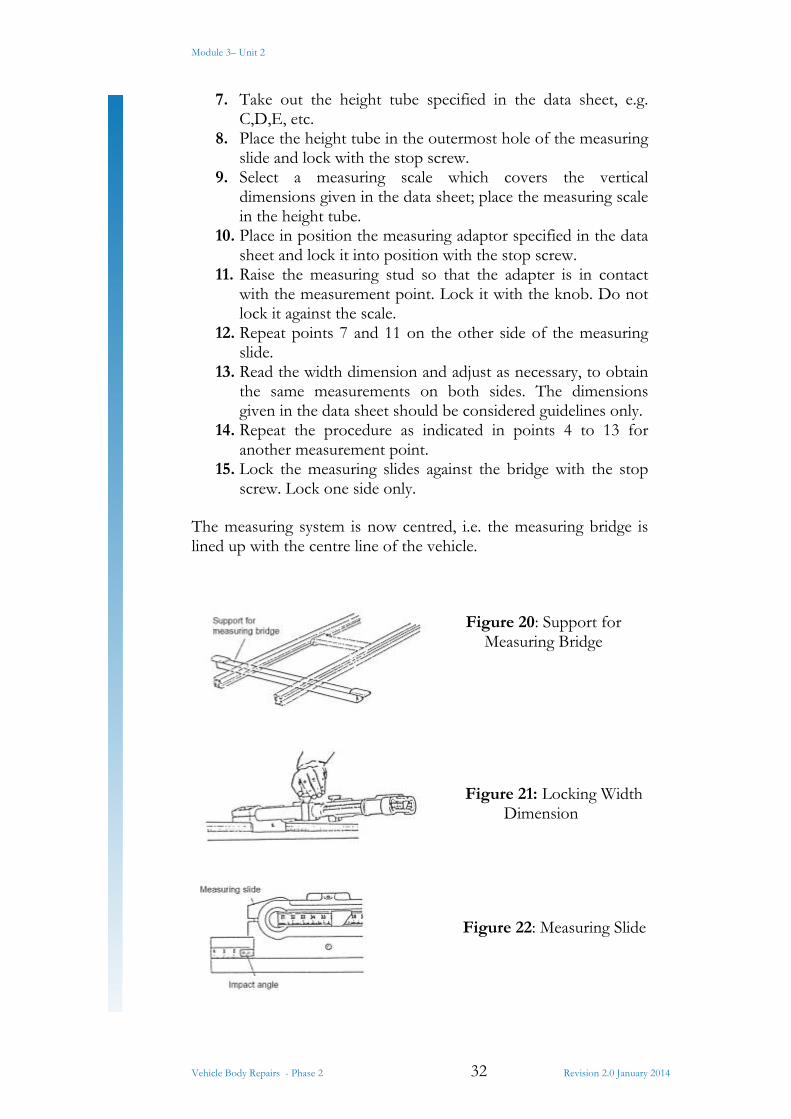
Figure 20: Support for Measuring Bridge
Figure 21: Locking Width Dimension
Figure 22: Measuring Slide
Module 3– Unit 2
Vehicle Body Repairs - Phase 2 33 Revision 2.0 January 2014
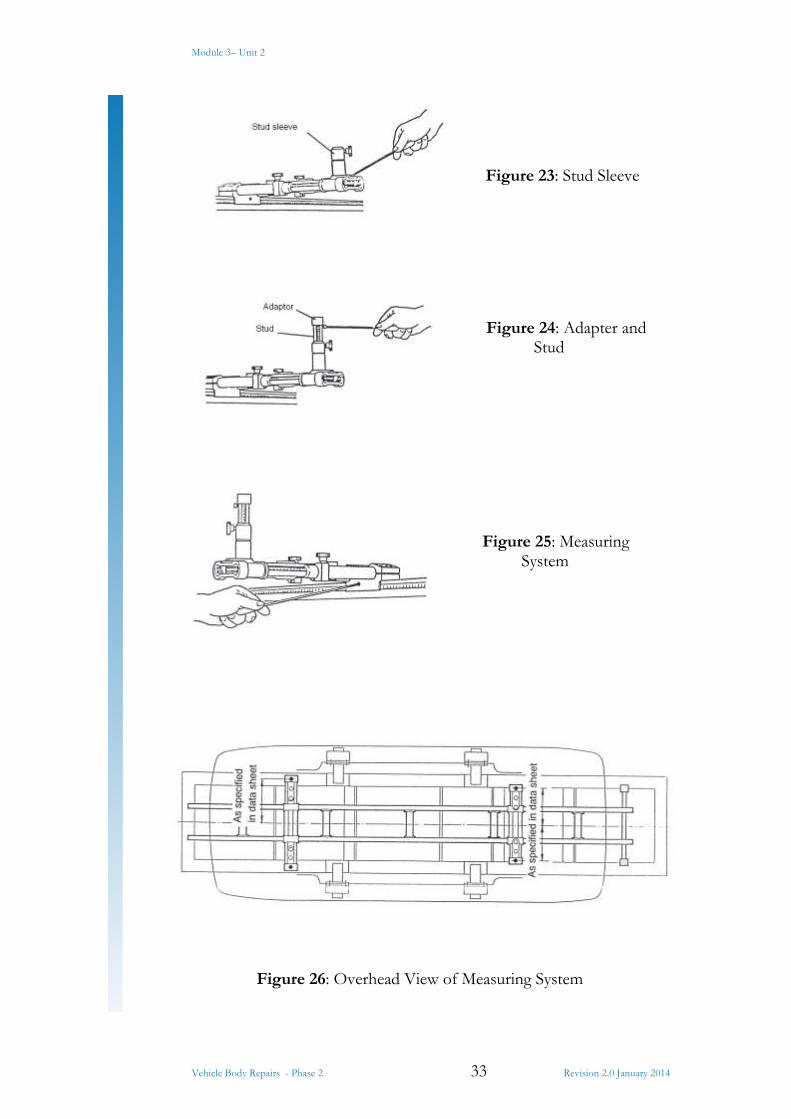
Figure 23: Stud Sleeve
Figure 24: Adapter and Stud
Figure 25: Measuring System
Figure 26: Overhead View of Measuring System
Module 3– Unit 2
Vehicle Body Repairs - Phase 2 34 Revision 2.0 January 2014
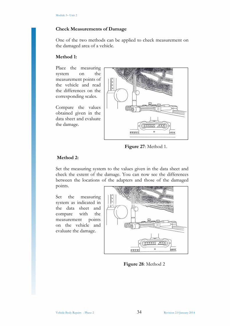
Check Measurements of Damage
One of the two methods can be applied to check measurement on the damaged area of a vehicle.
Method 1:
Place the measuring system on the measurement points of the vehicle and read the differences on the corresponding scales.
Compare the values obtained given in the data sheet and evaluate the damage.
Figure 27: Method 1.
Method 2:
Set the measuring system to the values given in the data sheet and check the extent of the damage. You can now see the differences between the locations of the adapters and those of the damaged points.
Set the measuring system as indicated in the data sheet and compare with the measurement points on the vehicle and evaluate the damage.
Figure 28: Method 2
Module 3– Unit 2
Vehicle Body Repairs - Phase 2 35 Revision 2.0 January 2014
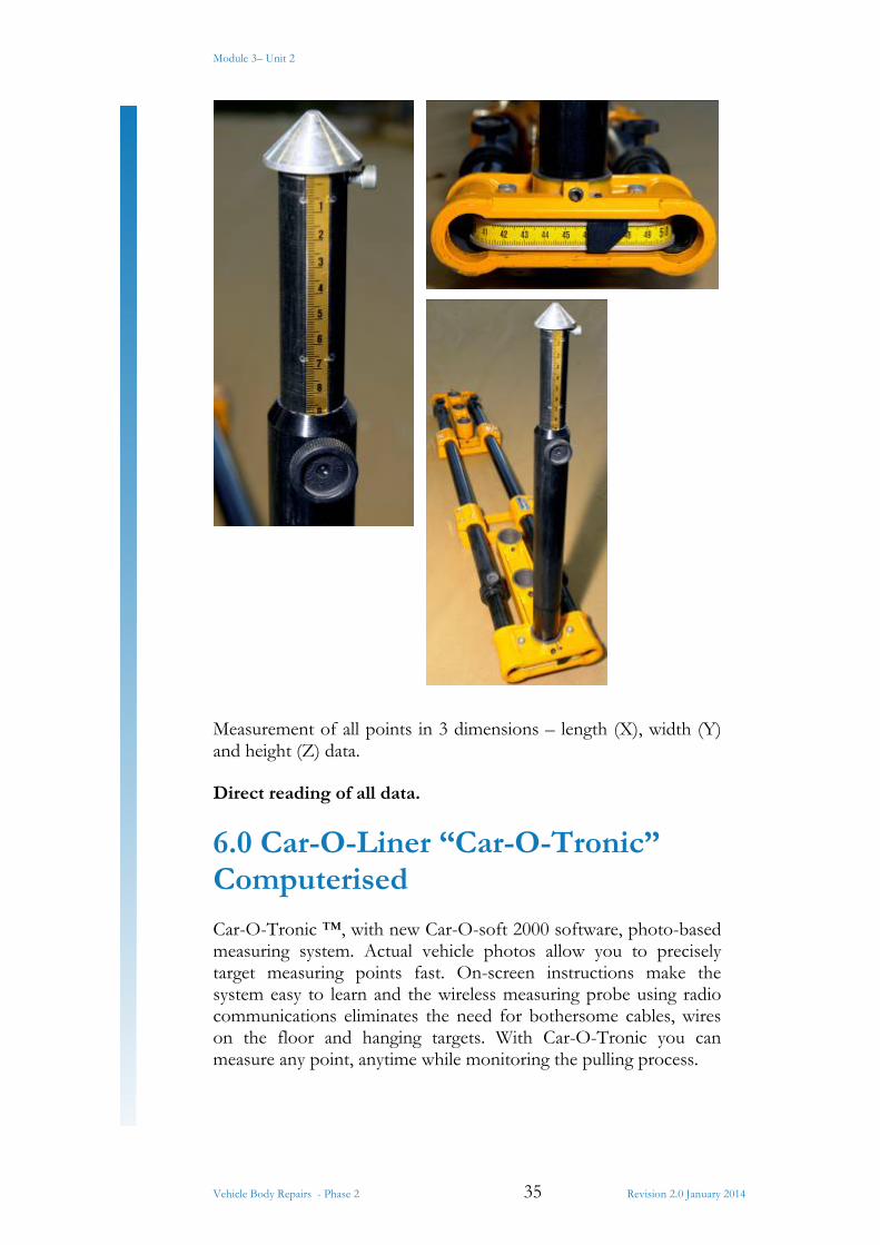
Measurement of all points in 3 dimensions – length (X), width (Y) and height (Z) data.
Direct reading of all data.
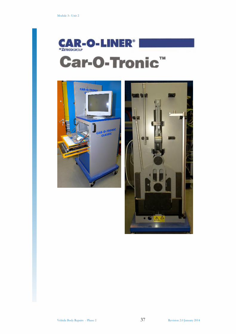
6.0 Car-O-Liner “Car-O-Tronic” Computerised
Car-O-Tronic ™, with new Car-O-soft 2000 software, photo-based measuring system. Actual vehicle photos allow you to precisely target measuring points fast. On-screen instructions make the system easy to learn and the wireless measuring probe using radio communications eliminates the need for bothersome cables, wires on the floor and hanging targets. With Car-O-Tronic you can measure any point, anytime while monitoring the pulling process.

Module 3– Unit 2
Vehicle Body Repairs - Phase 2 36 Revision 2.0 January 2014
Car-O-Tronic is completely compatible with almost any collision repair system you might have in your shop. It’s easy to move from bay to bay, damage analysis can be done even before the vehicle is put on the repair bench. Making Car-O-Tronic gives you the speed and accuracy you need to make better repairs, faster than ever. That adds up to greater productivity.
Figure 29: Measuring System on a Variety of Benches
Module 3– Unit 2
Vehicle Body Repairs - Phase 2 37 Revision 2.0 January 2014
Module 3– Unit 2
Vehicle Body Repairs - Phase 2 38 Revision 2.0 January 2014
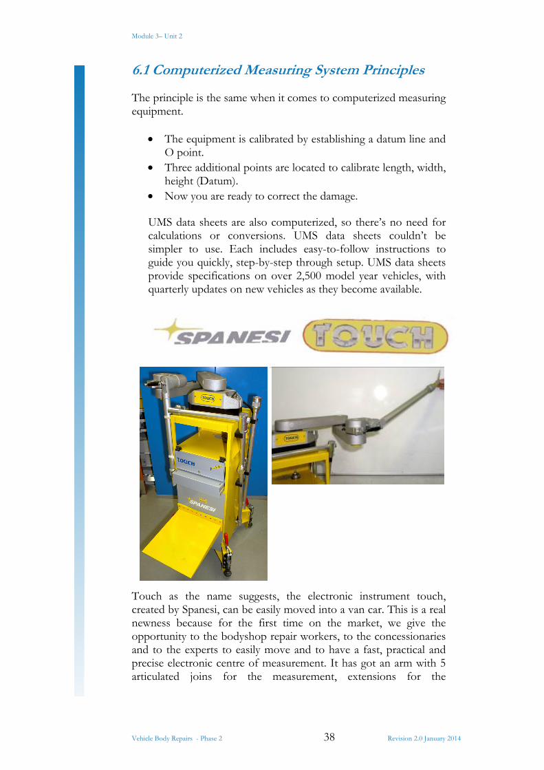
6.1 Computerized Measuring System Principles
The principle is the same when it comes to computerized measuring equipment.
The equipment is calibrated by establishing a datum line and O point.
Three additional points are located to calibrate length, width, height (Datum).
Now you are ready to correct the damage.
UMS data sheets are also computerized, so there’s no need for calculations or conversions. UMS data sheets couldn’t be simpler to use. Each includes easy-to-follow instructions to guide you quickly, step-by-step through setup. UMS data sheets provide specifications on over 2,500 model year vehicles, with quarterly updates on new vehicles as they become available.
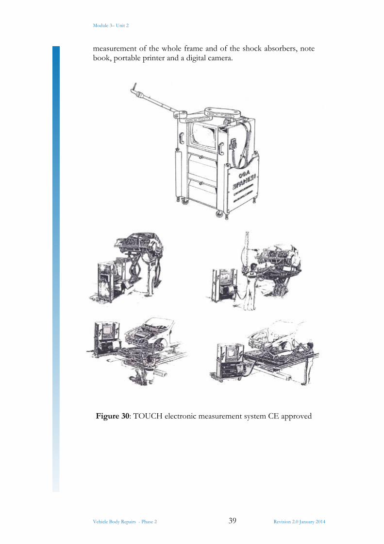
Touch as the name suggests, the electronic instrument touch, created by Spanesi, can be easily moved into a van car. This is a real newness because for the first time on the market, we give the opportunity to the bodyshop repair workers, to the concessionaries and to the experts to easily move and to have a fast, practical and precise electronic centre of measurement. It has got an arm with 5 articulated joins for the measurement, extensions for the
Module 3– Unit 2
Vehicle Body Repairs - Phase 2 39 Revision 2.0 January 2014
measurement of the whole frame and of the shock absorbers, note book, portable printer and a digital camera.
Figure 30: TOUCH electronic measurement system CE approved
Module 3– Unit 2
Vehicle Body Repairs - Phase 2 40 Revision 2.0 January 2014
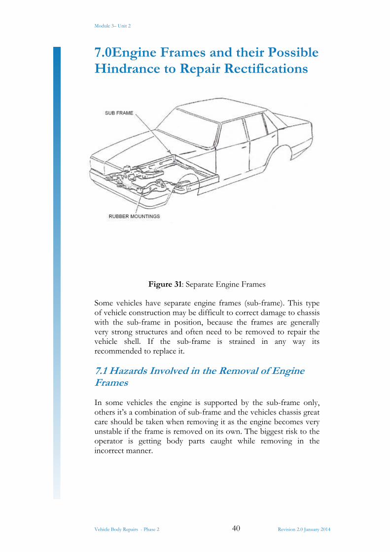
7.0Engine Frames and their Possible Hindrance to Repair Rectifications
Figure 31: Separate Engine Frames
Some vehicles have separate engine frames (sub-frame). This type of vehicle construction may be difficult to correct damage to chassis with the sub-frame in position, because the frames are generally very strong structures and often need to be removed to repair the vehicle shell. If the sub-frame is strained in any way its recommended to replace it.
7.1 Hazards Involved in the Removal of Engine Frames
In some vehicles the engine is supported by the sub-frame only, others it’s a combination of sub-frame and the vehicles chassis great care should be taken when removing it as the engine becomes very unstable if the frame is removed on its own. The biggest risk to the operator is getting body parts caught while removing in the incorrect manner.
Module 3– Unit 2
Vehicle Body Repairs - Phase 2 41 Revision 2.0 January 2014
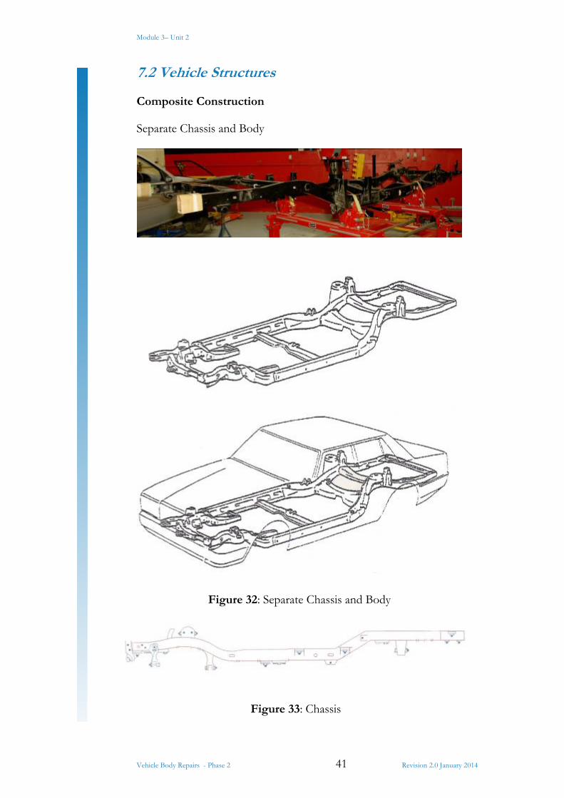
7.2 Vehicle Structures
Composite Construction
Separate Chassis and Body
Figure 32: Separate Chassis and Body
Figure 33: Chassis
Module 3– Unit 2
Vehicle Body Repairs - Phase 2 42 Revision 2.0 January 2014
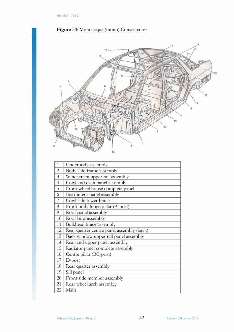
Figure 34: Monocoque (mono) Construction
1 Underbody assembly2 Body side frame assembly3 Windscreen upper rail assembly4 Cowl and dash panel assembly5 Front wheel house complete panel6 Instrument panel assembly7 Cowl side lower brace8 Front body hinge pillar (A-post)9 Roof panel assembly10 Roof bow assembly11 Bulkhead brace assembly12 Rear quarter centre panel assembly (back)13 Back window upper rail panel assembly14 Rear-end upper panel assembly15 Radiator panel complete assembly16 Centre pillar (BC-post)17 D-post 18 Rear quarter assembly19 Sill panel 20 Front side member assembly21 Rear wheel arch assembly22 Main

Module 3– Unit 2
Vehicle Body Repairs - Phase 2 43 Revision 2.0 January 2014
8.0 The Effect of Damage on a Vehicle
Figure 35: Statistics on Angles of Damage Impact
As can be seen frontal damage dominate the scene.
Frontal damage should always be repaired in an aligning bench due to the fact that the steering and wheel mountings are mounted in the front.
Module 3– Unit 2
Vehicle Body Repairs - Phase 2 44 Revision 2.0 January 2014
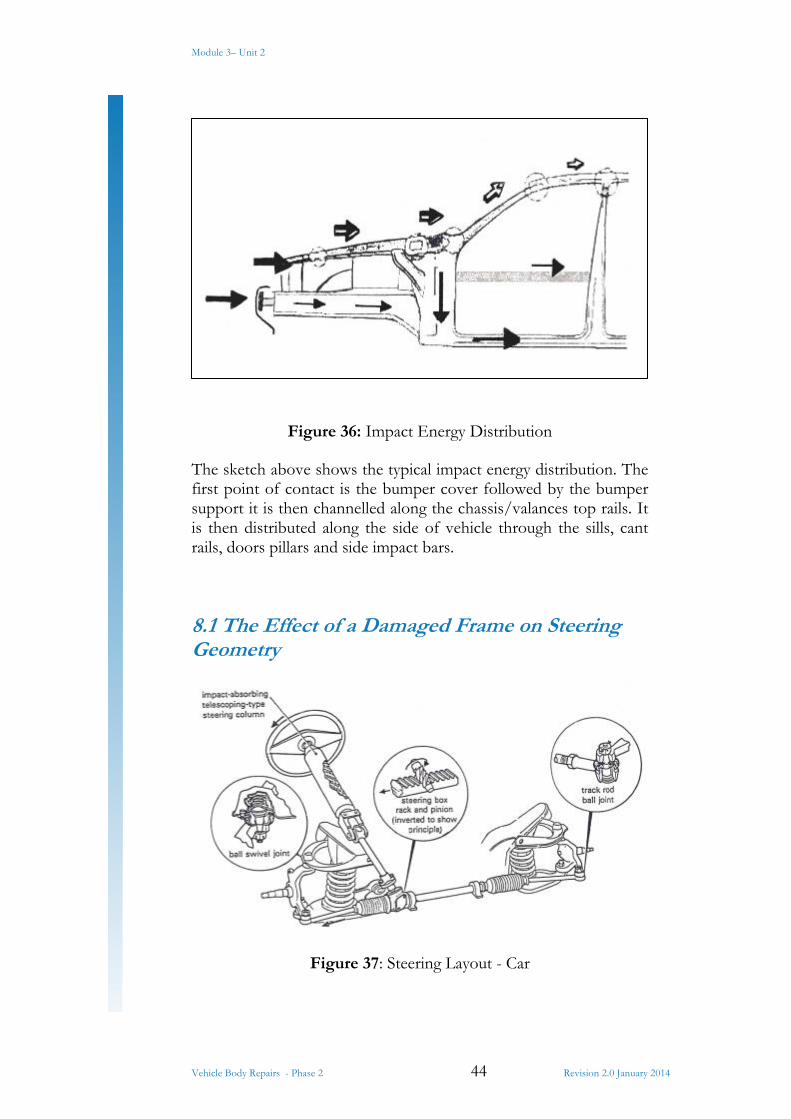
Figure 36: Impact Energy Distribution
The sketch above shows the typical impact energy distribution. The first point of contact is the bumper cover followed by the bumper support it is then channelled along the chassis/valances top rails. It is then distributed along the side of vehicle through the sills, cant rails, doors pillars and side impact bars.
8.1 The Effect of a Damaged Frame on Steering Geometry
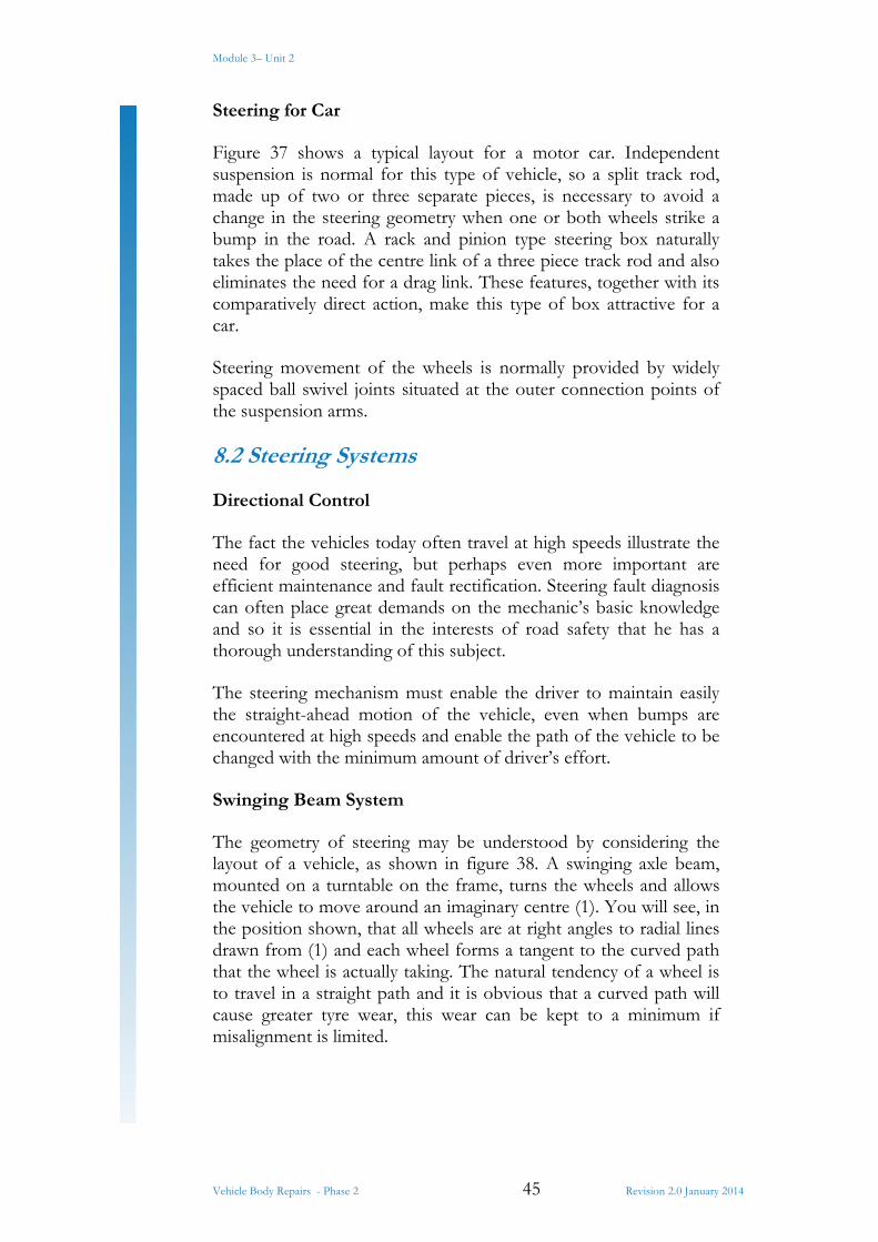
Figure 37: Steering Layout - Car
Module 3– Unit 2
Vehicle Body Repairs - Phase 2 45 Revision 2.0 January 2014
Steering for Car
Figure 37 shows a typical layout for a motor car. Independent suspension is normal for this type of vehicle, so a split track rod, made up of two or three separate pieces, is necessary to avoid a change in the steering geometry when one or both wheels strike a bump in the road. A rack and pinion type steering box naturally takes the place of the centre link of a three piece track rod and also eliminates the need for a drag link. These features, together with its comparatively direct action, make this type of box attractive for a car.
Steering movement of the wheels is normally provided by widely spaced ball swivel joints situated at the outer connection points of the suspension arms.
8.2 Steering Systems
Directional Control
The fact the vehicles today often travel at high speeds illustrate the need for good steering, but perhaps even more important are efficient maintenance and fault rectification. Steering fault diagnosis can often place great demands on the mechanic’s basic knowledge and so it is essential in the interests of road safety that he has a thorough understanding of this subject.
The steering mechanism must enable the driver to maintain easily the straight-ahead motion of the vehicle, even when bumps are encountered at high speeds and enable the path of the vehicle to be changed with the minimum amount of driver’s effort.
Swinging Beam System
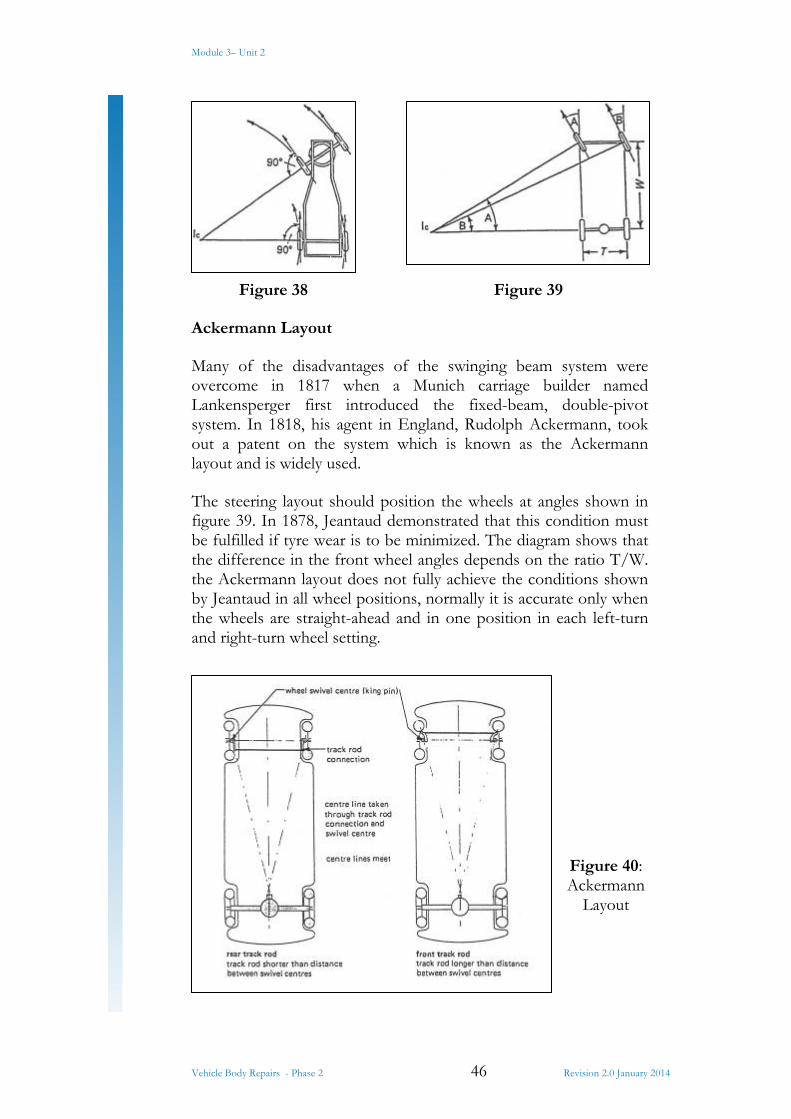
The geometry of steering may be understood by considering the layout of a vehicle, as shown in figure 38. A swinging axle beam, mounted on a turntable on the frame, turns the wheels and allows the vehicle to move around an imaginary centre (1). You will see, in the position shown, that all wheels are at right angles to radial lines drawn from (1) and each wheel forms a tangent to the curved path that the wheel is actually taking. The natural tendency of a wheel is to travel in a straight path and it is obvious that a curved path will cause greater tyre wear, this wear can be kept to a minimum if misalignment is limited.
Module 3– Unit 2
Vehicle Body Repairs - Phase 2 46 Revision 2.0 January 2014
Figure 38 Figure 39
Ackermann Layout
Many of the disadvantages of the swinging beam system were overcome in 1817 when a Munich carriage builder named Lankensperger first introduced the fixed-beam, double-pivot system. In 1818, his agent in England, Rudolph Ackermann, took out a patent on the system which is known as the Ackermann layout and is widely used.
The steering layout should position the wheels at angles shown in figure 39. In 1878, Jeantaud demonstrated that this condition must be fulfilled if tyre wear is to be minimized. The diagram shows that the difference in the front wheel angles depends on the ratio T/W. the Ackermann layout does not fully achieve the conditions shown by Jeantaud in all wheel positions, normally it is accurate only when the wheels are straight-ahead and in one position in each left-turn and right-turn wheel setting.
Figure 40: Ackermann
Layout
Module 3– Unit 2
Vehicle Body Repairs - Phase 2 47 Revision 2.0 January 2014
The main details of the layout are shown in figure 40. Each wheel hub is mounted on a stub axle which swivels on either ball joints or a king pin to give the steering action. Linkage connecting the two stub axles together comprises two track arms and a track rod. The Ackermann layout is obtained by positioning the king pin (or swivel joints) and the track rod joint on an imaginary line which is inclined to the centreline of the vehicle. This means that when a track rod is fitted to the rear of the swivel centres, it is shorter than the distance between swivel centres. Although this is satisfactory on heavy vehicles, it is not used on cars because of the engine position, instead the track rod is set forward of the wheel centres.
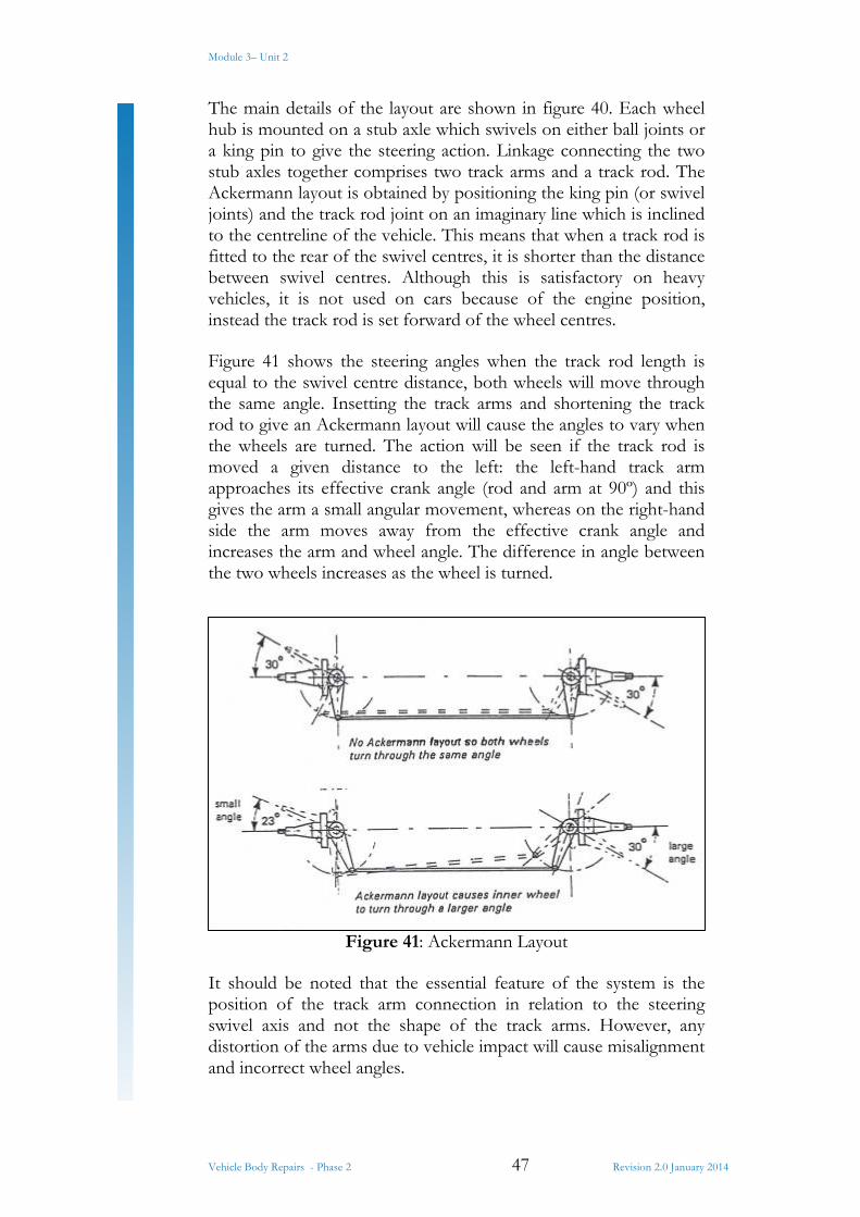
Figure 41 shows the steering angles when the track rod length is equal to the swivel centre distance, both wheels will move through the same angle. Insetting the track arms and shortening the track rod to give an Ackermann layout will cause the angles to vary when the wheels are turned. The action will be seen if the track rod is moved a given distance to the left: the left-hand track arm approaches its effective crank angle (rod and arm at 90º) and this gives the arm a small angular movement, whereas on the right-hand side the arm moves away from the effective crank angle and increases the arm and wheel angle. The difference in angle between the two wheels increases as the wheel is turned.
Figure 41: Ackermann Layout
It should be noted that the essential feature of the system is the position of the track arm connection in relation to the steering swivel axis and not the shape of the track arms. However, any distortion of the arms due to vehicle impact will cause misalignment and incorrect wheel angles.
Module 3– Unit 2
Vehicle Body Repairs - Phase 2 48 Revision 2.0 January 2014
The setting of the track arms can be either by placing the wheels on turntables and measuring the angles, or by checking the amount that the wheels move out-of-parallel when one wheel is steered through a given angle – this latter test is called ‘toe-out on turns’.
Oversteer and Understeer
Slip Angle
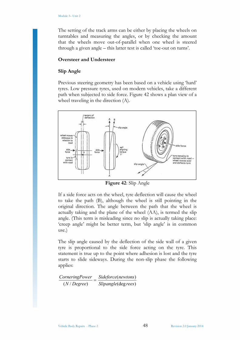
Previous steering geometry has been based on a vehicle using ‘hard’ tyres. Low pressure tyres, used on modern vehicles, take a different path when subjected to side force. Figure 42 shows a plan view of a wheel traveling in the direction (A).
Figure 42: Slip Angle
If a side force acts on the wheel, tyre deflection will cause the wheel to take the path (B), although the wheel is still pointing in the original direction. The angle between the path that the wheel is actually taking and the plane of the wheel (AA), is termed the slip angle. (This term is misleading since no slip is actually taking place: ‘creep angle’ might be better term, but ‘slip angle’ is in common use.)
The slip angle caused by the deflection of the side wall of a given tyre is proportional to the side force acting on the tyre. This statement is true up to the point where adhesion is lost and the tyre starts to slide sideways. During the non-slip phase the following applies:
)/( DegreeN
owerCorneringP
)(deg
)(
reesSlipangle
newtonsSideforce
Module 3– Unit 2
Vehicle Body Repairs - Phase 2 49 Revision 2.0 January 2014
The cornering power (c.p) of a tyre is governed by:
1. Inflation pressure – an increase raises the c.p. 2. Tyre construction – a radial-ply tyre has a higher c.p. than a
diagonal-ply tyre. 3. Tyre size – a low profile tyre has a smaller wall so a higher
c.p. is achieved. 4. Camber (tilt) of wheel – tilting the wheel away from the side
force increase the c.p. 5. Load on the wheel – if the load is varied from the normal,
then c.p. will decrease.
Self-Aligning Torque
When a side force acts on a tyre the wall deflects to give a slip angle. Observing a wheel that is rotating in this condition shows that the side deflection of the tyre is greater at the point where the tyre leaves the road as it revolves. This effect produces a self aligning torque (t) which attempts to turn the wheel to align itself with the actual direction that the wheel is taking.
The effect of the torque is felt by a driver of a vehicle which is traveling along a highly cambered road – the steering will ‘pull’ to one side.
Oversteer and Understeer
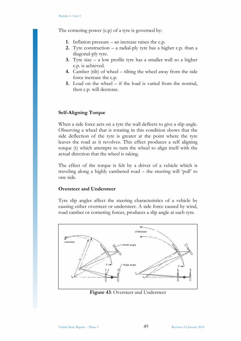
Tyre slip angles affect the steering characteristics of a vehicle by causing either oversteer or understeer. A side force caused by wind, road camber or cornering forces, produces a slip angle at each tyre.
Figure 43: Oversteer and Understeer
Module 3– Unit 2
Vehicle Body Repairs - Phase 2 50 Revision 2.0 January 2014
When the rear slip angles are greater than the front (figure 43), the vehicle will turn more sharply than the normal – a condition called oversteer. To correct for this, the driver has to strengthen up the steering wheel – a difficult feat under cornering conditions and when this is linked with the fact that the sharper the turn causes a further increase in the cornering force, then it will be apparent why oversteer is regarded as dangerous. A mixed tyre arrangement which uses radial ply on the front and diagonal ply on the rear increase the oversteer effect, so for safety reasons it is made illegal to use this tyre arrangement.
Oversteer can also be caused by:
1. Moving the centre of gravity towards the rear by increasing the load on the rear of the vehicle.
2. Lower tyre inflation pressure at the rear than that recommended.
3. Large load transference from inner rear wheel to outer rear wheel when cornering.
Understeer is produced when the front slip angles are greater than the rear. This tends to cause the vehicle to move away from the side force and makes the vehicle take a path of larger radius than normal. A reasonable degree of understeer is desirable, but if it becomes excessive, ‘hard’ steering results.
Steering Mechanism
The mechanism used to link the driver’s steering wheel to the road wheels depends on the type of suspension system. Modern layouts have been developed from the basic system. Today the use of this system is confined to light trucks.
Steering for a Light Truck
The steering column, set at an angle to suit the driving position, contains a shaft (mast), which is connected to the spoked steering wheel, either by a taper and key or by splines. At the lower end of the column, a steering gearbox is fitted and this moves a drop arm. A ball joint on the bottom end of the arm joins it to a drag link which pushes and pulls a steering arm mounted on a stub axle.
Module 3– Unit 2
Vehicle Body Repairs - Phase 2 51 Revision 2.0 January 2014
8.3 Camber, Castor and Swivel-axis Inclination
Centre-Point Steering
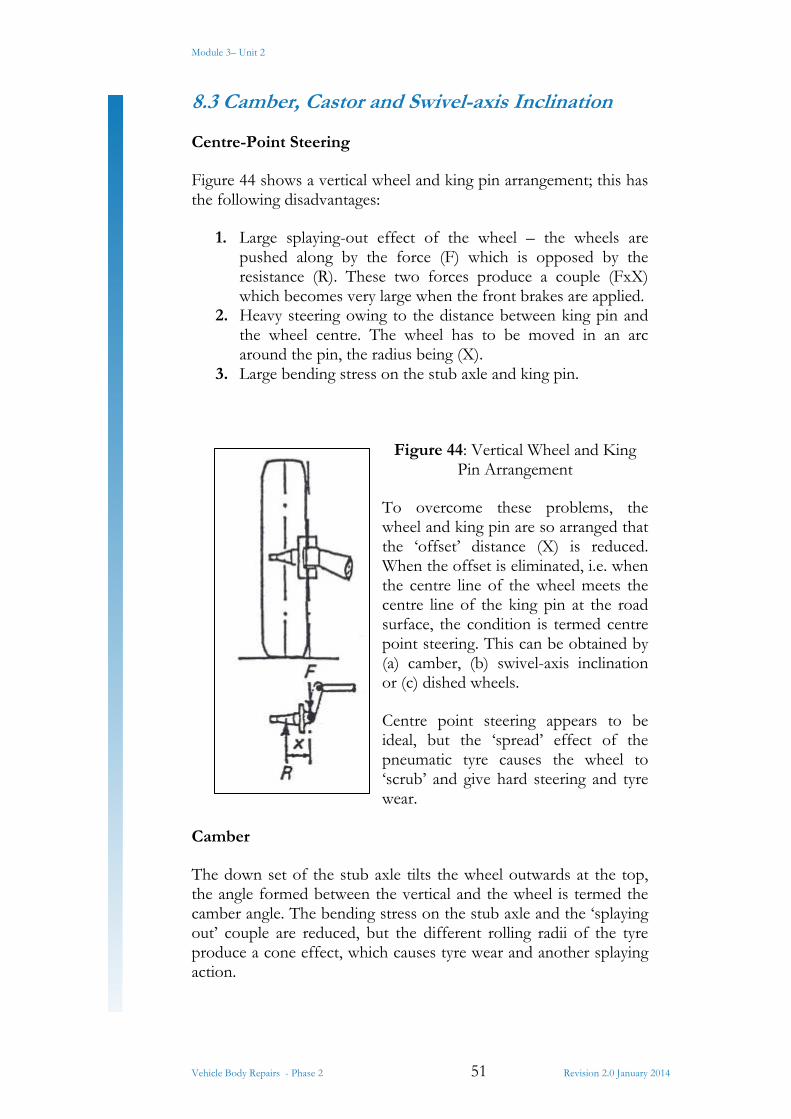
Figure 44 shows a vertical wheel and king pin arrangement; this has the following disadvantages:
1. Large splaying-out effect of the wheel – the wheels are pushed along by the force (F) which is opposed by the resistance (R). These two forces produce a couple (FxX) which becomes very large when the front brakes are applied.
2. Heavy steering owing to the distance between king pin and the wheel centre. The wheel has to be moved in an arc around the pin, the radius being (X).
3. Large bending stress on the stub axle and king pin.
Figure 44: Vertical Wheel and King Pin Arrangement
To overcome these problems, the wheel and king pin are so arranged that the ‘offset’ distance (X) is reduced. When the offset is eliminated, i.e. when the centre line of the wheel meets the centre line of the king pin at the road surface, the condition is termed centre point steering. This can be obtained by (a) camber, (b) swivel-axis inclination or (c) dished wheels.
Centre point steering appears to be ideal, but the ‘spread’ effect of the pneumatic tyre causes the wheel to ‘scrub’ and give hard steering and tyre wear.
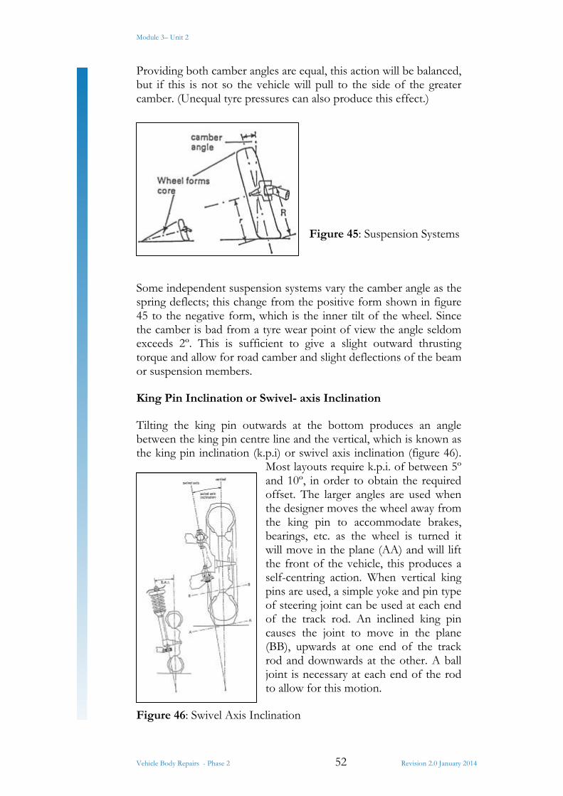
Camber
The down set of the stub axle tilts the wheel outwards at the top, the angle formed between the vertical and the wheel is termed the camber angle. The bending stress on the stub axle and the ‘splaying out’ couple are reduced, but the different rolling radii of the tyre produce a cone effect, which causes tyre wear and another splaying action.
Module 3– Unit 2
Vehicle Body Repairs - Phase 2 52 Revision 2.0 January 2014
Providing both camber angles are equal, this action will be balanced, but if this is not so the vehicle will pull to the side of the greater camber. (Unequal tyre pressures can also produce this effect.)
Figure 45: Suspension Systems
Some independent suspension systems vary the camber angle as the spring deflects; this change from the positive form shown in figure 45 to the negative form, which is the inner tilt of the wheel. Since the camber is bad from a tyre wear point of view the angle seldom exceeds 2º. This is sufficient to give a slight outward thrusting torque and allow for road camber and slight deflections of the beam or suspension members.
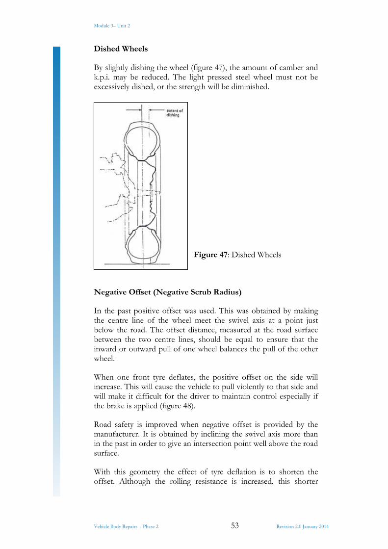
King Pin Inclination or Swivel- axis Inclination
Tilting the king pin outwards at the bottom produces an angle between the king pin centre line and the vertical, which is known as the king pin inclination (k.p.i) or swivel axis inclination (figure 46).
Most layouts require k.p.i. of between 5º and 10º, in order to obtain the required offset. The larger angles are used when the designer moves the wheel away from the king pin to accommodate brakes, bearings, etc. as the wheel is turned it will move in the plane (AA) and will lift the front of the vehicle, this produces a self-centring action. When vertical king pins are used, a simple yoke and pin type of steering joint can be used at each end of the track rod. An inclined king pin causes the joint to move in the plane (BB), upwards at one end of the track rod and downwards at the other. A ball joint is necessary at each end of the rod to allow for this motion.
Figure 46: Swivel Axis Inclination
Module 3– Unit 2
Vehicle Body Repairs - Phase 2 53 Revision 2.0 January 2014
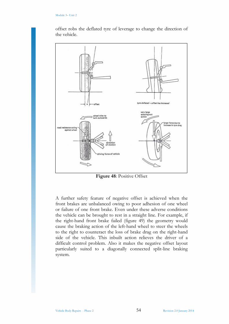
Dished Wheels
By slightly dishing the wheel (figure 47), the amount of camber and k.p.i. may be reduced. The light pressed steel wheel must not be excessively dished, or the strength will be diminished.
Figure 47: Dished Wheels
Negative Offset (Negative Scrub Radius)
In the past positive offset was used. This was obtained by making the centre line of the wheel meet the swivel axis at a point just below the road. The offset distance, measured at the road surface between the two centre lines, should be equal to ensure that the inward or outward pull of one wheel balances the pull of the other wheel.
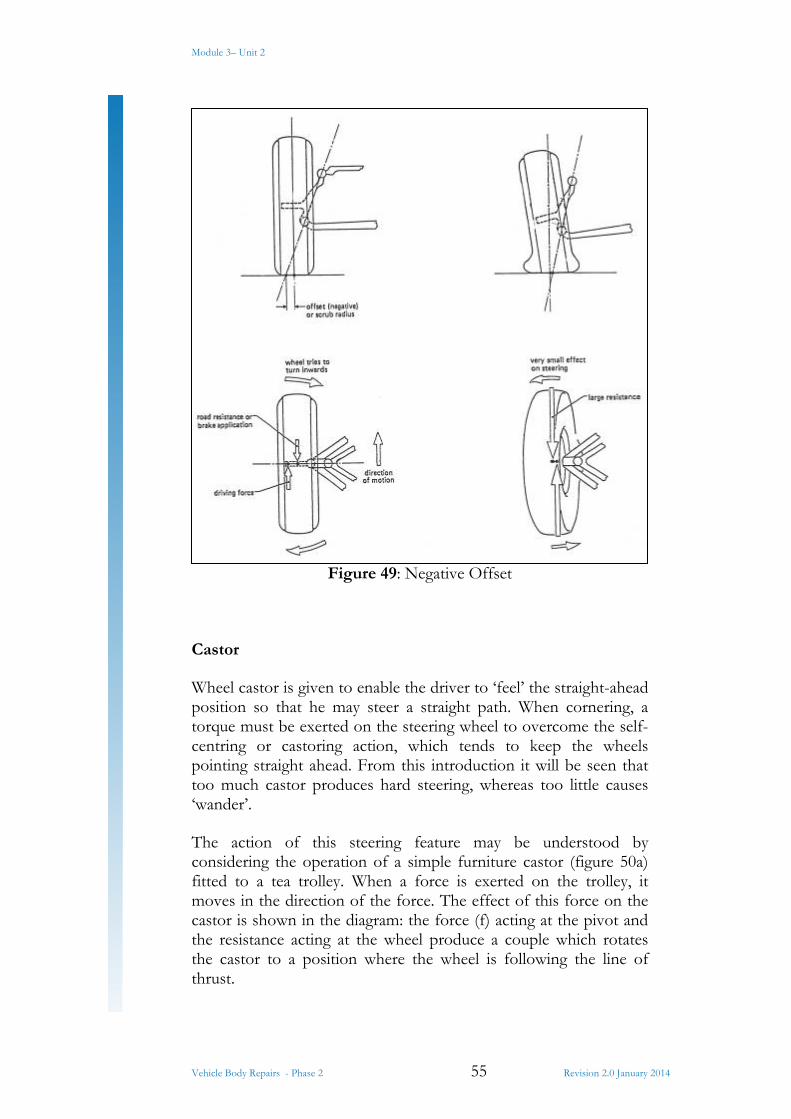
When one front tyre deflates, the positive offset on the side will increase. This will cause the vehicle to pull violently to that side and will make it difficult for the driver to maintain control especially if the brake is applied (figure 48).
Road safety is improved when negative offset is provided by the manufacturer. It is obtained by inclining the swivel axis more than in the past in order to give an intersection point well above the road surface.
With this geometry the effect of tyre deflation is to shorten the offset. Although the rolling resistance is increased, this shorter
Module 3– Unit 2
Vehicle Body Repairs - Phase 2 54 Revision 2.0 January 2014
offset robs the deflated tyre of leverage to change the direction of the vehicle.
Figure 48: Positive Offset
A further safety feature of negative offset is achieved when the front brakes are unbalanced owing to poor adhesion of one wheel or failure of one front brake. Even under these adverse conditions the vehicle can be brought to rest in a straight line. For example, if the right-hand front brake failed (figure 49) the geometry would cause the braking action of the left-hand wheel to steer the wheels to the right to counteract the loss of brake drag on the right-hand side of the vehicle. This inbuilt action relieves the driver of a difficult control problem. Also it makes the negative offset layout particularly suited to a diagonally connected split-line braking system.
Module 3– Unit 2
Vehicle Body Repairs - Phase 2 55 Revision 2.0 January 2014
Figure 49: Negative Offset
Castor
Wheel castor is given to enable the driver to ‘feel’ the straight-ahead position so that he may steer a straight path. When cornering, a torque must be exerted on the steering wheel to overcome the self-centring or castoring action, which tends to keep the wheels pointing straight ahead. From this introduction it will be seen that too much castor produces hard steering, whereas too little causes ‘wander’.
The action of this steering feature may be understood by considering the operation of a simple furniture castor (figure 50a) fitted to a tea trolley. When a force is exerted on the trolley, it moves in the direction of the force. The effect of this force on the castor is shown in the diagram: the force (f) acting at the pivot and the resistance acting at the wheel produce a couple which rotates the castor to a position where the wheel is following the line of thrust.
Module 3– Unit 2
Vehicle Body Repairs - Phase 2 56 Revision 2.0 January 2014
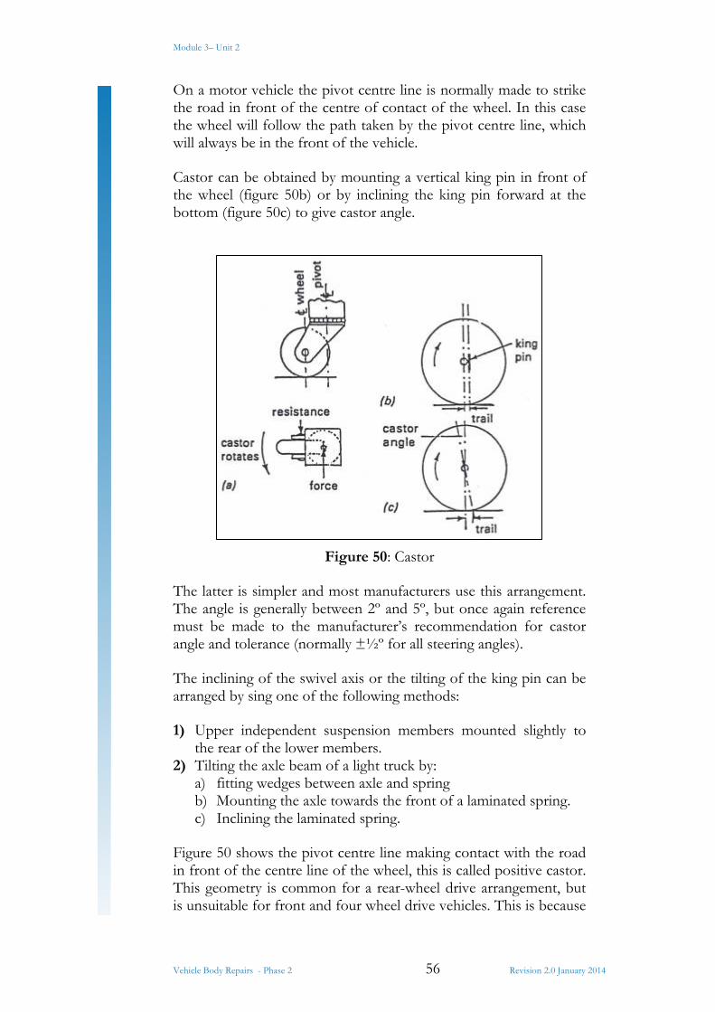
On a motor vehicle the pivot centre line is normally made to strike the road in front of the centre of contact of the wheel. In this case the wheel will follow the path taken by the pivot centre line, which will always be in the front of the vehicle.
Castor can be obtained by mounting a vertical king pin in front of the wheel (figure 50b) or by inclining the king pin forward at the bottom (figure 50c) to give castor angle.
Figure 50: Castor
The latter is simpler and most manufacturers use this arrangement. The angle is generally between 2º and 5º, but once again reference must be made to the manufacturer’s recommendation for castor angle and tolerance (normally ±½º for all steering angles).
The inclining of the swivel axis or the tilting of the king pin can be arranged by sing one of the following methods:
1) Upper independent suspension members mounted slightly to the rear of the lower members.
2) Tilting the axle beam of a light truck by: a) fitting wedges between axle and spring b) Mounting the axle towards the front of a laminated spring. c) Inclining the laminated spring.
Figure 50 shows the pivot centre line making contact with the road in front of the centre line of the wheel, this is called positive castor. This geometry is common for a rear-wheel drive arrangement, but is unsuitable for front and four wheel drive vehicles. This is because
Module 3– Unit 2
Vehicle Body Repairs - Phase 2 57 Revision 2.0 January 2014
the conditions shown in figure 50 are then reversed. Most vehicles that use the front wheels as driving wheels have negative castor, but since this only a general rule, reference to the manufacturer’s data should be made when checking the steering geometry.
Wheel Alignment
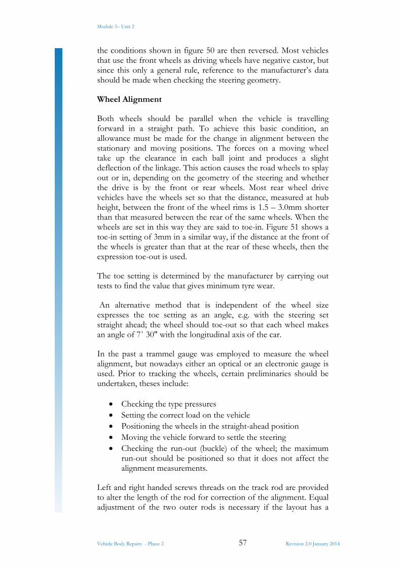
Both wheels should be parallel when the vehicle is travelling forward in a straight path. To achieve this basic condition, an allowance must be made for the change in alignment between the stationary and moving positions. The forces on a moving wheel take up the clearance in each ball joint and produces a slight deflection of the linkage. This action causes the road wheels to splay out or in, depending on the geometry of the steering and whether the drive is by the front or rear wheels. Most rear wheel drive vehicles have the wheels set so that the distance, measured at hub height, between the front of the wheel rims is 1.5 – 3.0mm shorter than that measured between the rear of the same wheels. When the wheels are set in this way they are said to toe-in. Figure 51 shows a toe-in setting of 3mm in a similar way, if the distance at the front of the wheels is greater than that at the rear of these wheels, then the expression toe-out is used.
The toe setting is determined by the manufacturer by carrying out tests to find the value that gives minimum tyre wear.
An alternative method that is independent of the wheel size expresses the toe setting as an angle, e.g. with the steering set straight ahead; the wheel should toe-out so that each wheel makes an angle of 7΄ 30" with the longitudinal axis of the car.
In the past a trammel gauge was employed to measure the wheel alignment, but nowadays either an optical or an electronic gauge is used. Prior to tracking the wheels, certain preliminaries should be undertaken, theses include:
Checking the type pressures Setting the correct load on the vehicle Positioning the wheels in the straight-ahead position Moving the vehicle forward to settle the steering Checking the run-out (buckle) of the wheel; the maximum
run-out should be positioned so that it does not affect the alignment measurements.
Left and right handed screws threads on the track rod are provided to alter the length of the rod for correction of the alignment. Equal adjustment of the two outer rods is necessary if the layout has a
Module 3– Unit 2
Vehicle Body Repairs - Phase 2 58 Revision 2.0 January 2014
rack and pinion steering box. Failure to do this will have two effects; firstly it will alter the position of the steering wheel with the result that the horizontal spokes will be misaligned and secondly the steering locks will be unequal.
Incorrect wheel alignment can be recognized by the wafer edge of rubber left on the side of the tread pattern after it has been scraped over the road surface (figure 51) an examination of the position of the feather gives an indication of the fault; a wafer of rubber on the inside of the tread suggests that the wheels are toed in and vice versa. This feathering of the tread is often more pronounced on one tyre than the other.
Figure 51: Wheel Alignment
The combination of road camber and the action of tyre’s self-righting torque causes both front wheels to turn towards the near-side. This movement affects the steering geometry and shows why a manufacturer may recommend a toe setting that appears to contradict basic theory. Interaction between the various geometry aspects of a modern vehicle makes it difficult to pinpoint the cause of a fault from a given symptom, so after carrying out the preliminaries, a front end check covering all aspects of geometry is advised.
An adjuster for wear wheel alignment is provided on some vehicles fitted with independent rear suspension.
Module 3– Unit 2
Vehicle Body Repairs - Phase 2 59 Revision 2.0 January 2014
8.4 Steering Components
Steering Gearbox
The steering gearbox provides the driver with a laver system to enable him to exert a large force at the road wheel with the minimum effort and to control the direction of vehicle motion accurately.
The overall ratio between the steering wheel and the road wheel varies from the road wheels and the type of steering.
As the ratio is lowered, a large number of turns are required to move the wheel from lock to lock; this makes it difficult to make a rapid change in vehicle direction.
By varying the efficiency, the degree of reversibility (a reversible gear transmits motion from steering wheel to drop arm and vice versa) can be controlled, to enable the driver to ‘feel’ the wheels, yet not subject him to major road shock.
Types of Steering Gear
Over the years a number of different types of steering box have been used, these include:
Worm and sector Screw and nut Recirculating ball Cam and peg Worm and roller Rack and pinion
Worm and Sector
This type has been developed from a worm and wheel which was one of the earliest designs of box.
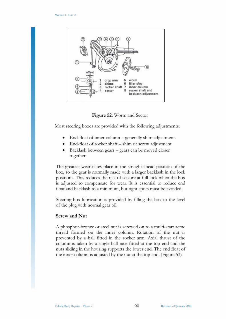
A case-hardened steel worm and sector are located by bearings in a malleable iron or light alloy casing. Figure 52 shows the worm connected to the inner column and the sector forming a part of the rocker shaft.
Module 3– Unit 2
Vehicle Body Repairs - Phase 2 60 Revision 2.0 January 2014
Figure 52: Worm and Sector
Most steering boxes are provided with the following adjustments:
End-float of inner column – generally shim adjustment. End-float of rocker shaft – shim or screw adjustment Backlash between gears – gears can be moved closer
together.
The greatest wear takes place in the straight-ahead position of the box, so the gear is normally made with a larger backlash in the lock positions. This reduces the risk of seizure at full lock when the box is adjusted to compensate for wear. It is essential to reduce end float and backlash to a minimum, but tight spots must be avoided.
Steering box lubrication is provided by filling the box to the level of the plug with normal gear oil.
Screw and Nut
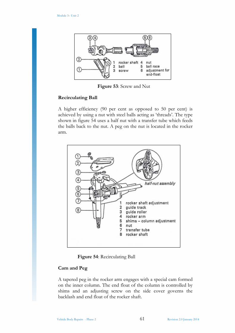
A phosphor-bronze or steel nut is screwed on to a multi-start acme thread formed on the inner column. Rotation of the nut is prevented by a ball fitted in the rocker arm. Axial thrust of the column is taken by a single ball race fitted at the top end and the nuts sliding in the housing supports the lower end. The end float of the inner column is adjusted by the nut at the top end. (Figure 53)
Module 3– Unit 2
Vehicle Body Repairs - Phase 2 61 Revision 2.0 January 2014
Figure 53: Screw and Nut
Recirculating Ball
A higher efficiency (90 per cent as opposed to 50 per cent) is achieved by using a nut with steel balls acting as ‘threads’. The type shown in figure 54 uses a half nut with a transfer tube which feeds the balls back to the nut. A peg on the nut is located in the rocker arm.
Figure 54: Recirculating Ball
Cam and Peg
A tapered peg in the rocker arm engages with a special cam formed on the inner column. The end float of the column is controlled by shims and an adjusting screw on the side cover governs the backlash and end float of the rocker shaft.

Module 3– Unit 2
Vehicle Body Repairs - Phase 2 62 Revision 2.0 January 2014
Figure 55: Cam and Peg
A modified form known as the high efficiency cam and peg gear uses a peg which is allowed to rotate in bearings in the rocker arm. (Figure 55)
Worm and Roller
A roller follower fitted to the rocker shaft engages with an hourglass worm. The small offset of the roller to the worm enables an adjusting screw to control backlash and end float of the rocker shaft. (Figure 56)
Figure 56: Worm and Roller
Rack and Pinion
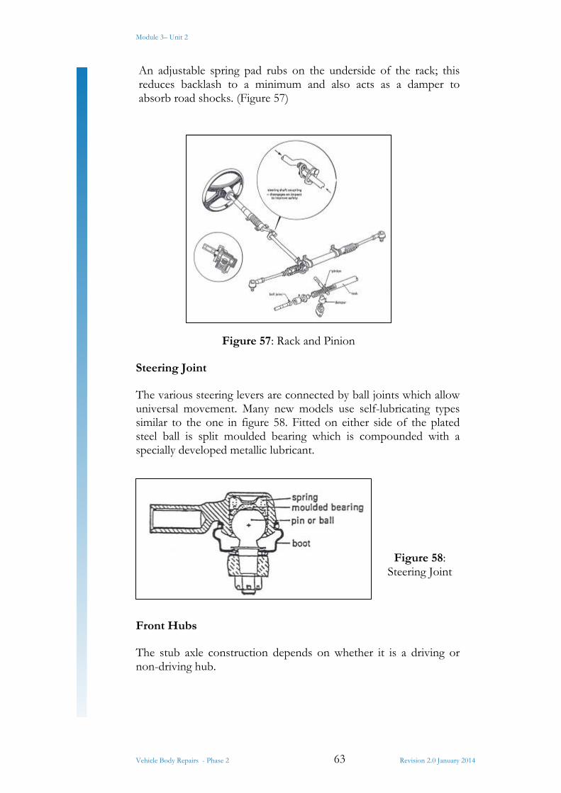
This type is often used with i.f.s where the rack acts as the centre section of a three-piece track rod. The pinion is normally connected to the column by a universal joint to enable the box to be centrally mounted. Each end of the rack has a ball connection to the track rod.
Module 3– Unit 2
Vehicle Body Repairs - Phase 2 63 Revision 2.0 January 2014
An adjustable spring pad rubs on the underside of the rack; this reduces backlash to a minimum and also acts as a damper to absorb road shocks. (Figure 57)
Figure 57: Rack and Pinion
Steering Joint
The various steering levers are connected by ball joints which allow universal movement. Many new models use self-lubricating types similar to the one in figure 58. Fitted on either side of the plated steel ball is split moulded bearing which is compounded with a specially developed metallic lubricant.
Figure 58: Steering Joint
Front Hubs
The stub axle construction depends on whether it is a driving or non-driving hub.
Module 3– Unit 2
Vehicle Body Repairs - Phase 2 64 Revision 2.0 January 2014
Non-Driving Hub
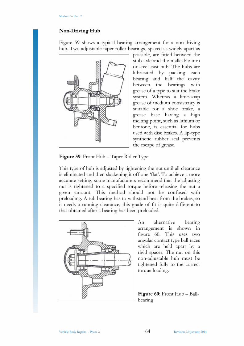
Figure 59 shows a typical bearing arrangement for a non-driving hub. Two adjustable taper roller bearings, spaced as widely apart as
possible, are fitted between the stub axle and the malleable iron or steel cast hub. The hubs are lubricated by packing each bearing and half the cavity between the bearings with grease of a type to suit the brake system. Whereas a lime-soap grease of medium consistency is suitable for a shoe brake, a grease base having a high melting point, such as lithium or bentone, is essential for hubs used with disc brakes. A lip-type synthetic rubber seal prevents the escape of grease.
Figure 59: Front Hub – Taper Roller Type
This type of hub is adjusted by tightening the nut until all clearance is eliminated and then slackening it off one ‘flat’. To achieve a more accurate setting, some manufacturers recommend that the adjusting nut is tightened to a specified torque before releasing the nut a given amount. This method should not be confused with preloading. A tub bearing has to withstand heat from the brakes, so it needs a running clearance; this grade of fit is quite different to that obtained after a bearing has been preloaded.
An alternative bearing arrangement is shown in figure 60. This uses two angular contact type ball races which are held apart by a rigid spacer. The nut on this non-adjustable hub must be tightened fully to the correct torque loading.
Figure 60: Front Hub – Ball-bearing
Module 3– Unit 2
Vehicle Body Repairs - Phase 2 65 Revision 2.0 January 2014
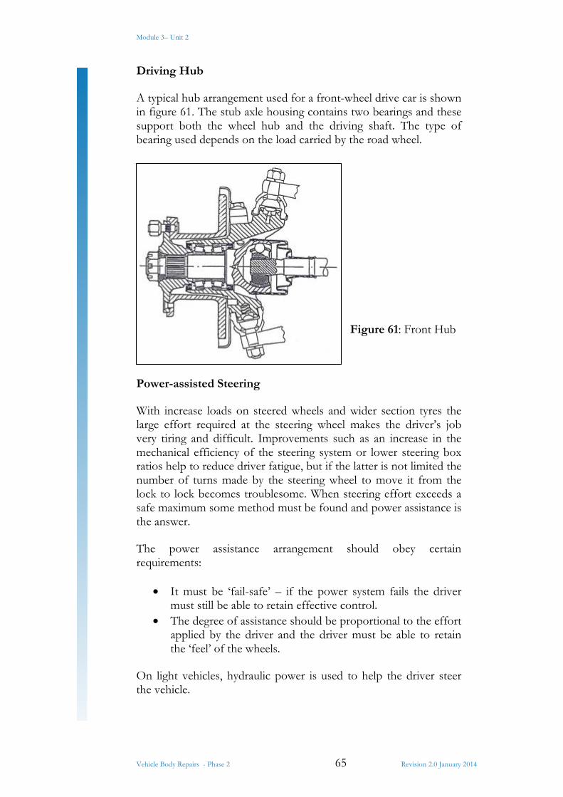
Driving Hub
A typical hub arrangement used for a front-wheel drive car is shown in figure 61. The stub axle housing contains two bearings and these support both the wheel hub and the driving shaft. The type of bearing used depends on the load carried by the road wheel.
Figure 61: Front Hub
Power-assisted Steering
With increase loads on steered wheels and wider section tyres the large effort required at the steering wheel makes the driver’s job very tiring and difficult. Improvements such as an increase in the mechanical efficiency of the steering system or lower steering box ratios help to reduce driver fatigue, but if the latter is not limited the number of turns made by the steering wheel to move it from the lock to lock becomes troublesome. When steering effort exceeds a safe maximum some method must be found and power assistance is the answer.
The power assistance arrangement should obey certain requirements:
It must be ‘fail-safe’ – if the power system fails the driver must still be able to retain effective control.
The degree of assistance should be proportional to the effort applied by the driver and the driver must be able to retain the ‘feel’ of the wheels.
On light vehicles, hydraulic power is used to help the driver steer the vehicle.
Module 3– Unit 2
Vehicle Body Repairs - Phase 2 66 Revision 2.0 January 2014
Hydraulic System
Hydraulically operated power-assisted systems are based on either a constant pressure or constant flow layout – the former employs a hydraulic accumulator to store the pressure, whereas the latter has fluid flowing around the system continuously until assistance is needed.
Figure 62 shows the essential components required to operate a constant flow system. In addition to the normal steering components the system requires a pump, control valve and ram cylinder.
Figure 62: Power-assisted Steering Layout
Pump
This is generally an eccentric rotor type driven by a vee belt from the engine crankshaft. Attached to the pump is a fluid reservoir and this normally contains a low-viscosity mineral oil similar to the type used in an automatic transmission. A pressure relief valve limits the maximum pressure 7MN/m² (10001bf/in²), and when this is reached the oil passes from the pump outlet back to the reservoir.
Control Valve (or reaction valve)
In figure 62 the valve is positioned between the two halves of the drag link, but in modern applications it can be included together with the ram cylinder in the steering box.
A spool-type valve, attached to one half of the drag link, is held centrally in the valve body by means of reaction springs. Flexible pipes connect the valve to the ram cylinder, pump and reservoir.
Ram Cylinder
A double-acting ram piston connects with the steering arm to supply the appropriate force to assist the drive. The force must act in either direction and this is achieved by venting one side and
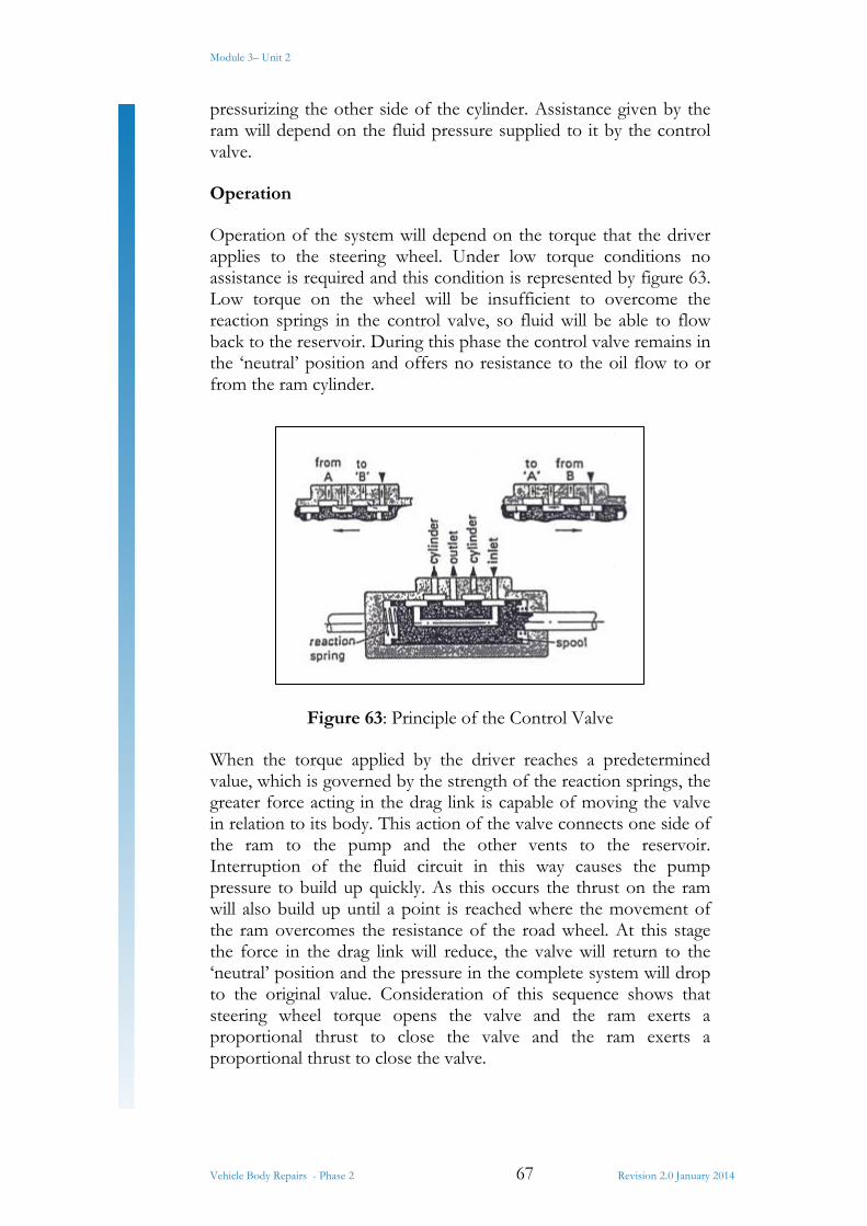
Module 3– Unit 2
Vehicle Body Repairs - Phase 2 67 Revision 2.0 January 2014
pressurizing the other side of the cylinder. Assistance given by the ram will depend on the fluid pressure supplied to it by the control valve.
Operation
Operation of the system will depend on the torque that the driver applies to the steering wheel. Under low torque conditions no assistance is required and this condition is represented by figure 63. Low torque on the wheel will be insufficient to overcome the reaction springs in the control valve, so fluid will be able to flow back to the reservoir. During this phase the control valve remains in the ‘neutral’ position and offers no resistance to the oil flow to or from the ram cylinder.
Figure 63: Principle of the Control Valve
When the torque applied by the driver reaches a predetermined value, which is governed by the strength of the reaction springs, the greater force acting in the drag link is capable of moving the valve in relation to its body. This action of the valve connects one side of the ram to the pump and the other vents to the reservoir. Interruption of the fluid circuit in this way causes the pump pressure to build up quickly. As this occurs the thrust on the ram will also build up until a point is reached where the movement of the ram overcomes the resistance of the road wheel. At this stage the force in the drag link will reduce, the valve will return to the ‘neutral’ position and the pressure in the complete system will drop to the original value. Consideration of this sequence shows that steering wheel torque opens the valve and the ram exerts a proportional thrust to close the valve and the ram exerts a proportional thrust to close the valve.
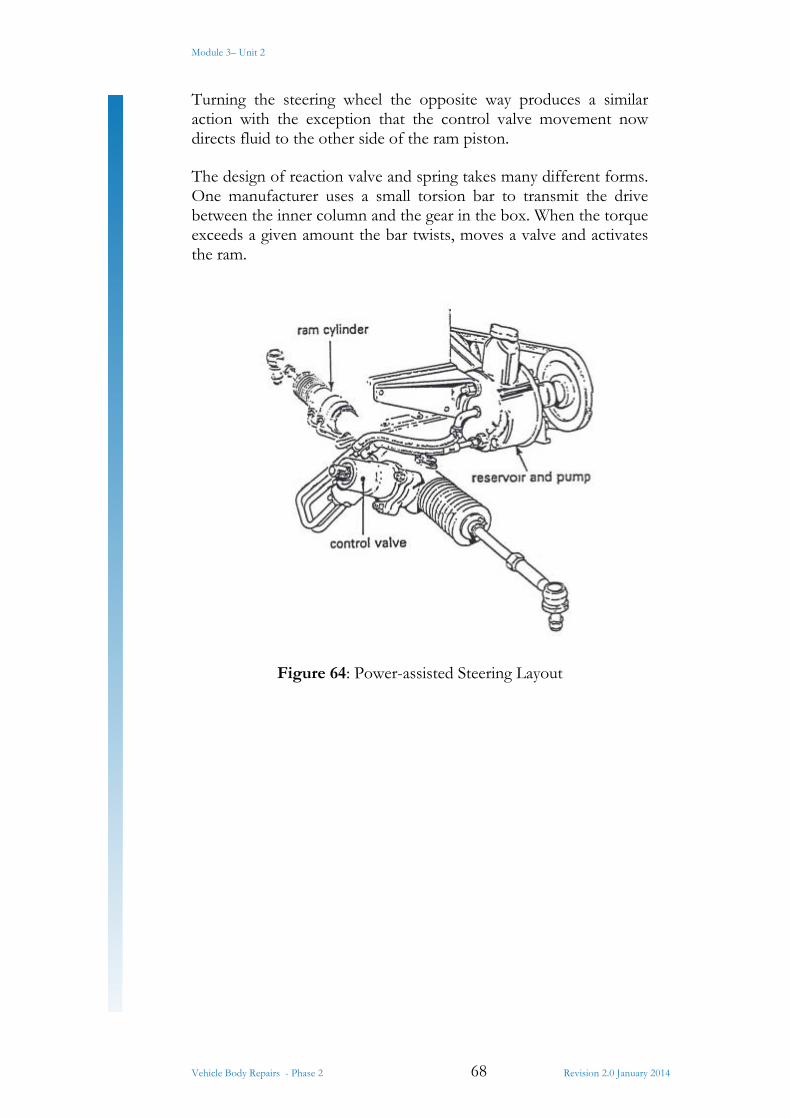
Module 3– Unit 2
Vehicle Body Repairs - Phase 2 68 Revision 2.0 January 2014
Turning the steering wheel the opposite way produces a similar action with the exception that the control valve movement now directs fluid to the other side of the ram piston.
The design of reaction valve and spring takes many different forms. One manufacturer uses a small torsion bar to transmit the drive between the inner column and the gear in the box. When the torque exceeds a given amount the bar twists, moves a valve and activates the ram.
Figure 64: Power-assisted Steering Layout
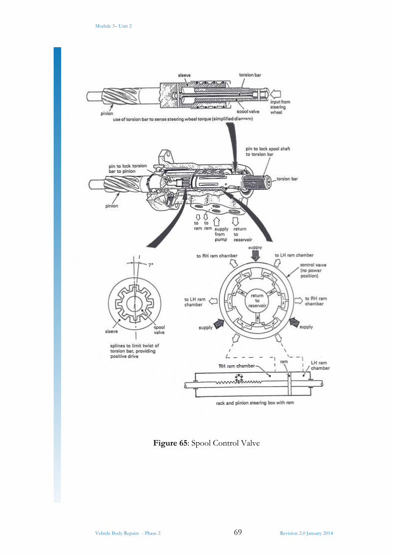
Module 3– Unit 2
Vehicle Body Repairs - Phase 2 69 Revision 2.0 January 2014
Figure 65: Spool Control Valve

Module 3– Unit 2
Vehicle Body Repairs - Phase 2 70 Revision 2.0 January 2014
Power-assisted Rack and Pinion Steering
The power steering system, shown in figure 64 is applied to a rack-and-pinion steering box.
The engine-driven hydraulic pump, which is integral with the reservoir, supplies oil to a control valve situated in the housing that supports the pinion shaft. Movement, imparted to the control valve from the shaft in the steering column, is via a torsion bar. This sensing bar moves the control valve, which in turn directs oil to one side or the other of the ram piston attached to the steering rack.
Control Valve
Figure 65 shows a simplified view of rotary-type spool valve controlled by a torsion bar that is interposed between the steering shaft and the pinion of the steering box. The spool valve is a shaft with six flutes and this is encased by a sleeve, which has six flutes and this is encased by a sleeve, which has six internal axial grooves. Radial ports in the sleeve and shaft pass oil from the supply to the lines connected to the ram chambers.
A series of splines between the shaft and sleeve limit the twist of the torsion bar to about 7º in each direction; below this angle the torque applied by the driver to the steering box pinion is transmitted by the torsion bar. This fail-safe feature provides a mechanical drive from the steering shaft to the pinion in the event of a failure of the power system.
The amount of twist of the torsion bar and the movement of the spool valve, are proportional to the effort applied by the driver. Initial power assistance is obtained at about 0.5º deflection of the bar and this power rises progressively as the bar moves to about 4º; the point of maximum assistance.
With the valve positioned in the ‘no-power’ position as shown in figure 65 all the ports are open, so oil is allowed to pass through the valve and return to the reservoir.
When the steering wheel is turned against a resistance at the road wheel, the torsion bar is deflected; this allows the spool to rotate relative to the sleeve, cutting off the oil flow both to the reservoir and one side of the ram. At the same time the other side of the ram is subjected to oil pressure which builds up sufficiently to move the road wheel and return the torsion bar to the no-torque position. During this stage the oil displaced from the unpressurized side of the ram is returned to the reservoir.

Module 3– Unit 2
Vehicle Body Repairs - Phase 2 71 Revision 2.0 January 2014
On occasions when the resistance to road wheel movement is excessive, the oil pressure builds up to its maximum. At this pressure a relief valve, fitted adjacent to the pump, opens and allows oil to return to the pump inlet.
Module 3– Unit 2
Vehicle Body Repairs - Phase 2 72 Revision 2.0 January 2014
Summary
The ever increasing pressure for workshops to produce quality repairs more efficiently has led to the development of high tech measuring equipment, this equipment is available in various forms such as mechanical measuring systems that provide the vehicle body repairer with data on most vehicles and a means of measuring it accurately. On the other hand computerised measuring systems allow the vehicle body repairer to produce an accurate before and after repair analysis of the vehicle which proves the accuracy of the repair via a print out which is given to the customer on completion of the work.
Module 3– Unit 2
Vehicle Body Repairs - Phase 2 73 Revision 2.0 January 2014
Self-Assessment
Questions – Module 3. Unit 2
1. What is a data sheet?
2. What is a measuring system?
3. What is a datum point?
4. Length, width and what are needed to measure a vehicle?
5. When measuring width where are measurements taken from?
Module 3– Unit 2
Vehicle Body Repairs - Phase 2 74 Revision 2.0 January 2014
6. What tool is needed to carry out a dropline test (measurement)?
7. What is a gun sight gauge?
8. What is a tramil gauge?
9. What is a symmetrical check?
10. What position must vehicles wheels be, in order to carry out a wheel base check?
11. What is a subframe?
Module 3– Unit 2
Vehicle Body Repairs - Phase 2 75 Revision 2.0 January 2014
12. A McPherson strut measuring system is also used to measure what?
13. What is a zero point?
14. What are the four most common methods of measuring a vehicle?
15. What is the most common point of impact on a vehicle?

Module 3– Unit 2
Vehicle Body Repairs - Phase 2 76 Revision 2.0 January 2014
Answers to Questions 1-15. Module 3. Unit 2
1.
A data sheet gives information on measurements of vehicles.
2.
A system that can measure any make of vehicle.
3.
It’s the first point (line) you set up.
4.
Height
5.
A centre line
6.
A plum weight
Module 3– Unit 2
Vehicle Body Repairs - Phase 2 77 Revision 2.0 January 2014
7.
A measuring tool to measure underbody by sighting pointers.
8.
A measuring tool to measure the distance between too fixed points accurately.
9.
A diagonal measurement is taken and checked symmetrically the opposite way.
10.
Straight ahead position.
11.
A removable frame section found on composite vehicles and some cars (e.g. Renault).
Module 3– Unit 2
Vehicle Body Repairs - Phase 2 78 Revision 2.0 January 2014
12.
Upper body measuring.
13.
A zero point is a point from which all other points distances are calculated and squared
14.
Mechanical measuring system Computerised measuring system Jig system Tramil system
15.
Front
Suggested Exercises
Mount a vehicle on a car bench and select the relevant vehicle data sheet.
Evaluate damaged area.
Analyse the measuring points to be used and apply measuring system to under body of vehicle, measure to manufacturer’s specifications.
Exercise
Instructions:
1) Mount a vehicle on a car bench; select the relevant vehicle data sheet. See Module 3 Unit 1.
2) Evaluate damaged area.
Although all vehicles receiving repair must be treated individually, the following is a basic approach to repair procedure:
Inspect and check underframe or chassis for alignment using conventional equipment.
Rectify any misalignment of underframe or chassis using hydraulic pulling equipment, hydraulic body jack and alignment jig fixtures.
Realign body shell, correcting damage with a combination of pulling equipment and body jack and the use of heat and hand tools. Also cut out and weld in any buckled panels or reinforcing members which are beyond repair.
Repair doors, fit glass and body trim to doors and check ease of operation and alignment of the door in the opening in the body shell. Also check alignment of bonnet and boat lid and ease of operation.
Smooth and finalize minor damage to body panels with hand tools. Replace all mechanical, trim and body parts. Replace windscreen and rear windows if necessary. Make an optical check on the vehicles steering geometry.
3) Analysis the measuring points to be used and apply measuring system to underbody of vehicle, measure to manufactures specifications.
4) Record data, fill in damage analysis form (manually). 5) Print electronic before and after data sheet.
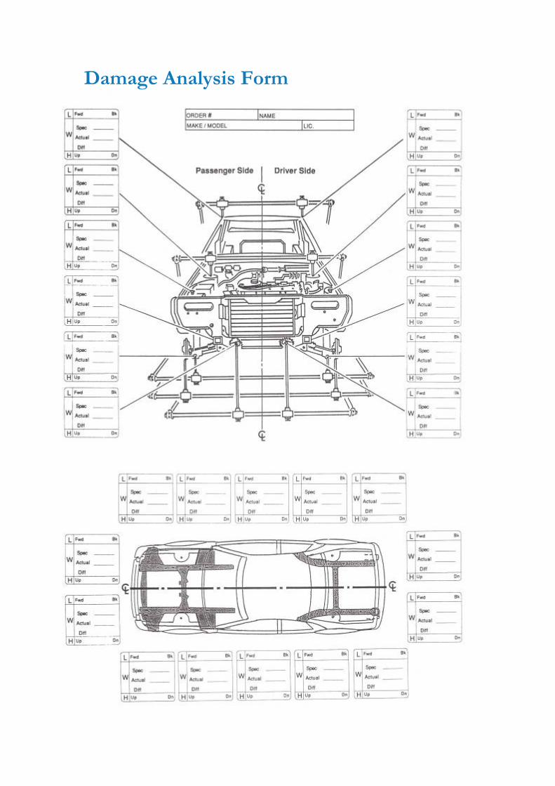
Damage Analysis Form

Training Resources
Classroom and workshop Universal measuring systems Selection of relevant vehicle data sheets Set of spanners Screw drivers Ratchet

27-33 Upper Baggot Street Dublin 4