training reort
DESCRIPTION
ReportTRANSCRIPT
A TRAINING REPORT
ON
WELDING AND TIME STUDY
DONE AT
Submitted by
AASHISH KUMAR PANWAR
10/FET/M(F)/1116
Under the Supervision of
MR. CHANDRASHEKHARASSIT. PROFESSOR(MECHANICAL)
in partial fulfillment for the award of the degree of
BACHELOR OF TECHNOLOGY
IN
MECHANICAL ENGINEERING
Faculty of Engineering & Technology
Manav Rachna International University, Faridabad
JULY-DECEMBER, 2013
Certificate
This is to certify that this training report entitled “WELDING AND TIME STUDY” by
AASHISH KUMAR PANWAR (10/FET/M(F)/1116), submitted in partial fulfillment of the
requirements for the degree of Bachelor of Technology in MECHANICAL ENGINEERING
under Faculty of Engineering & Technology of Manav Rachna International University
Faridabad, during the academic year 2010-2014, is a bonafide record of work carried out under
my guidance and supervision.
NIKHIL VERMA
WELDING HEAD
JAY BHARAT MARUTI
GURGAON

Acknowledgement
I would like to express our sincere gratitude to my training supervisor “NIKHIL VERMA” for
giving me the opportunity to work on this topic. It would never be possible for me to take this
training to this level without his innovative ideas and his relentless support and encouragement.
AASHISH KUMAR PANWAR (10/FET/M(F)/1116)

CONTENTS
1. Introduction of the company
2. History of company
3. Groups of the company
4. Guiding principles at JBML
5. Milestones of the company
6. Departments in JBM
7. KAIZEN and Poka Yoke
8. Welding
9. Exhaust System
10. Member Set Floor
11. YR-9 (WAGON R)
12. YE-3 ( ALTO)
13. YL-8 ( ERTIGA)
14. Conclusion
15. References

PREFACE
If one has to succeed in life, one has to keep pace with changing times this saying holds good in
every field of life be it general or professional. Being the student of the professional courses we
have to keep a constant vigil on rapidly changing environments. Is Indian industry a protected
one? Except some strategically important industries, every field is thrown to global competition,
liberalization and globalization combined with the privatization of existing public sector
companies is the new mantra of Indian economic policies. So in this era of tough competition
only fittest will survive. Industries spend a lot of capital in making the best out of the availability
and improving the present scenario every time.
With the purpose of getting myself abreast with the new trends in improvement management I
went for six months inplant training at “JAY BHARAT MARUTI LIMITED”. On the basis of
what I have learnt in the company I am here by submitting a report.
AASHISH KUMAR PANWAR
INTRODUCTION OF THE COMPANY
JBM is a multi unit, multi product group with extensive and diversified interests in engineering
and precision tooling, dies and chemicals and textiles and facilities spread over different parts of
the country. JBM group began its engineering activity in 1983 with the establishment of Gurera
gas cylinder limited and entered the auto component industries in 1985 with the inception of
SUZUKI AUTO INDIA. The JBML engineering groups deals in broad range of sheet metal
assemblies, die casting components and forging for the domestic and export markets. The
working environment at JBML is based on Japanese systems of manufacturing. 300 trained and
highly motivated personnel are the company’s greatest asset. The core group works closely with
its staff and workers to provide solution and create new goals for JBML. Owing to company’s
policy of continual improvement, use of latest manufacturing technologies, establishing effective
quality management system, continually improving employee skills, JBML has constantly been
upgrading and improving company’s resources.
HISTORY OF THE COMPANY
Jay Bharat Maruti Limited was set up in 1987. It is one of the largest joint ventures of Maruti
Udyog Limited. This is a unique combination of modern Press Shop and Weld Shop capable
of supplying components with successfully meeting customer’s quality and quantity
requirements. Manufacturing facilities at JBML also include die maintenance, dedicated
facilities for manufacturing exhaust systems and in house modern tool room. JBML is rising
to meet new challenges with modern equipment and higher goals of manufacturing and
quality control.
GROUPS OF THE COMPANY
The JBM group has following established plants:-
1. Jay Bharat Maruti Limited
2. JBM Auto Components Limited
3. JBM Industries Limited
GUIDING PRINCIPLES AT JBML
MISSION
To make JBML a synonym for world class organization excelling in sheet metal
technologies.
VISION
Expanding leadership in our business through people keeping pace with market trends
and technology.
HR POLICY
JBML will always keep on striving for the deployment of competent and efficient
employees at all levels to create inculcate and foster excellent working and learning
environment, because it believes in nurturing strength of individuals for developing
mutual trust, support and positive attitude for achieving organization goals to create a
world class manufacturing organization and to remain the market leader in sheet metal
components not only today but for all the tomorrows to come.
QUALITY POLICY
The policy of JBML is to achieve total customer satisfaction by delivering products and
providing services that meet or exceed their exacting requirements and expectations and
to do so on time and at most competitive prices in domestic and export market for our
entire product range.
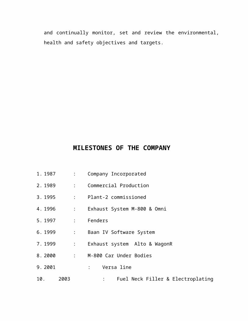
ENVIRONMENT, HEALTH AND SAFETY POLICY
Jay Bharat Maruti Limited, as a responsible manufacturer of sheet metal components,
welded sub assemblies and exhaust systems for automotive applications, re-affirms its
commitment to minimize the adverse impacts of its operations, products and services on
the environment, health and safety. To this end, the company endeavor to develop and
maintain an Environment, Health and Safety Management System and continually
monitor, set and review the environmental, health and safety objectives and targets.
MILESTONES OF THE COMPANY
1. 1987 : Company Incorporated
2. 1989 : Commercial Production
3. 1995 : Plant-2 commissioned
4. 1996 : Exhaust System M-800 & Omni
5. 1997 : Fenders
6. 1999 : Baan IV Software System
7. 1999 : Exhaust system Alto & WagonR
8. 2000 : M-800 Car Under Bodies
9. 2001 : Versa line
10. 2003 : Fuel Neck Filler & Electroplating
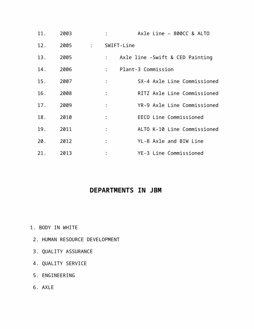
11. 2003 : Axle Line – 800CC & ALTO
12. 2005 : SWIFT-Line
13. 2005 : Axle line –Swift & CED Painting
14. 2006 : Plant-3 Commission
15. 2007 : SX-4 Axle Line Commissioned
16. 2008 : RITZ Axle Line Commissioned
17. 2009 : YR-9 Axle Line Commissioned
18. 2010 : EECO Line Commissioned
19. 2011 : ALTO K-10 Line Commissioned
20. 2012 : YL-8 Axle and BIW Line
21. 2013 : YE-3 Line Commissioned

DEPARTMENTS IN JBM
1. BODY IN WHITE
2. HUMAN RESOURCE DEVELOPMENT
3. QUALITY ASSURANCE
4. QUALITY SERVICE
5. ENGINEERING
6. AXLE
7. MATERIAL EXCHANGE
8. PLANT MAINTENANCE
9. EXHAUST
10. PURCHASE
11. RAW MATERIAL
12. FINANCE
13. PERSONAL AND ADMINISTRATION
KAIZEN
Kaizen is the small improvements in production as a result of continuous efforts covering all
areas and all employees. The difference between Kaizen and Innovation is that Innovation.
Involves a drastic improvement as a result of large investment in new equipment or new
technology.
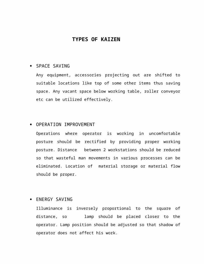
TYPES OF KAIZEN
SPACE SAVING
Any equipment, accessories projecting out are shifted to suitable locations like top of
some other items thus saving space. Any vacant space below working table, roller
conveyor etc can be utilized effectively.
OPERATION IMPROVEMENT
Operations where operator is working in uncomfortable posture should be rectified by
providing proper working posture. Distance between 2 workstations should be reduced
so that wasteful man movements in various processes can be eliminated. Location of
material storage or material flow should be proper.
ENERGY SAVING
Illuminance is inversely proportional to the square of distance, so lamp should be
placed closer to the operator. Lamp position should be adjusted so that shadow of
operator does not affect his work.
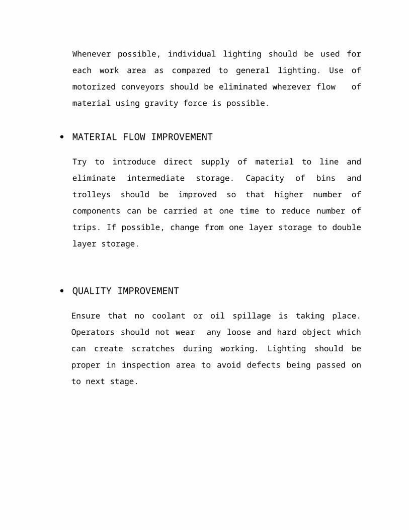
Whenever possible, individual lighting should be used for each work area as compared to
general lighting. Use of motorized conveyors should be eliminated wherever flow of
material using gravity force is possible.
MATERIAL FLOW IMPROVEMENT
Try to introduce direct supply of material to line and eliminate intermediate storage.
Capacity of bins and trolleys should be improved so that higher number of components
can be carried at one time to reduce number of trips. If possible, change from one layer
storage to double layer storage.
QUALITY IMPROVEMENT
Ensure that no coolant or oil spillage is taking place. Operators should not wear any
loose and hard object which can create scratches during working. Lighting should be
proper in inspection area to avoid defects being passed on to next stage.
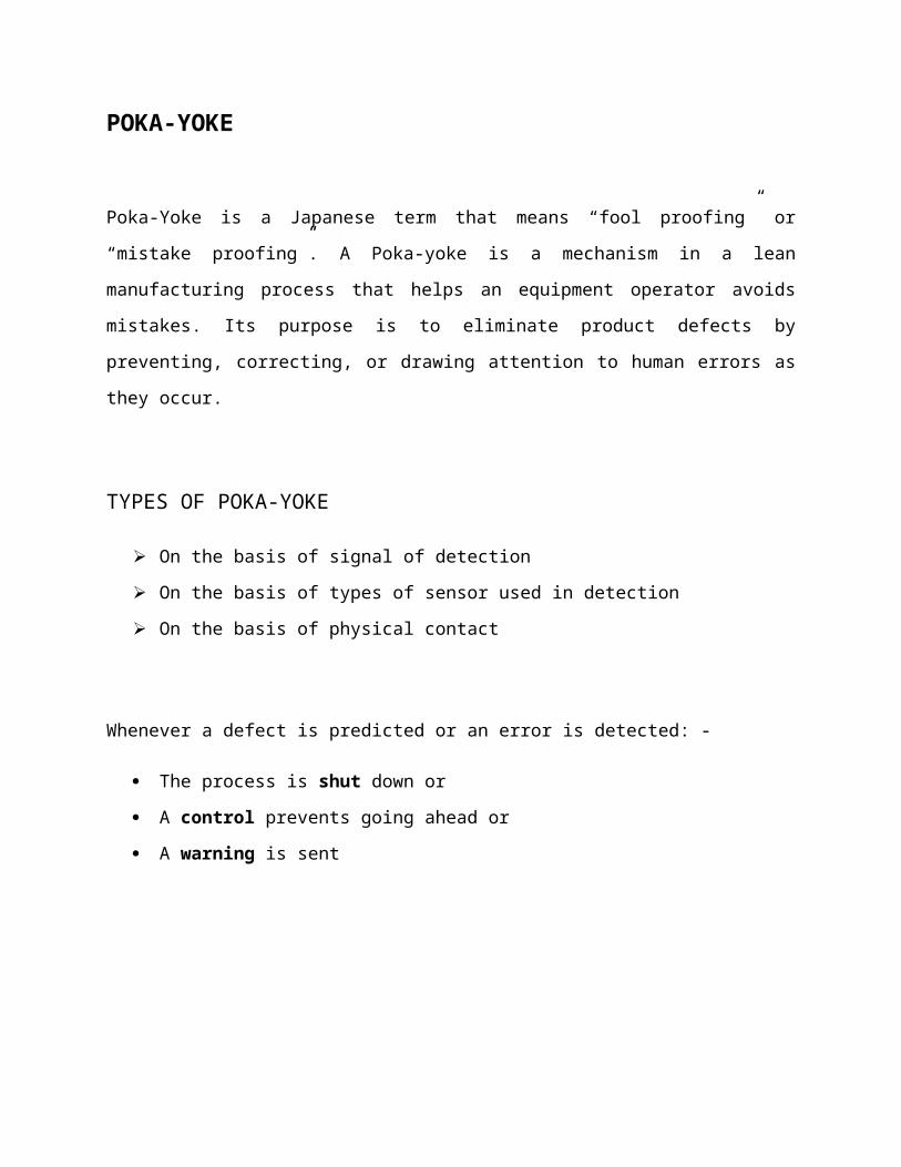
POKA-YOKE
Poka-Yoke is a Japanese term that means “fool proofing” or “mistake proofing”. A Poka-yoke is
a mechanism in a lean manufacturing process that helps an equipment operator avoids mistakes.
Its purpose is to eliminate product defects by preventing, correcting, or drawing attention to
human errors as they occur.
TYPES OF POKA-YOKE
On the basis of signal of detection
On the basis of types of sensor used in detection
On the basis of physical contact
Whenever a defect is predicted or an error is detected: -
The process is shut down or
A control prevents going ahead or
A warning is sent
WELDING
Welding is the process of permanently joining two or more metal parts, by melting both
materials. The molten materials quickly cool, and the two metals are permanently bonded.
TYPES OF WELDING DONE AT JBM
1. RESISTANCE WELDING ( SPOT WELDING)
2. MIG WELDING
3. MAG WELDING
RESISTANCE WELDING (SPOT WELDING)
Spot welding is done with the help of electrodes. Firstly, we approach the parts which is being
spot welded. With the help of high current, the parts are heated up to plastic flow of materials
takes place and then immediately pressing them by electrodes with high pressure.
Spot welding is primarily used for joining parts normally up to 3 mm (0.125 inch) thickness.
Spot-weld diameters range from 3 mm to 12.5 mm (0.125 to 0.5 inch).Low carbon steel is most
suitable for spot welding.
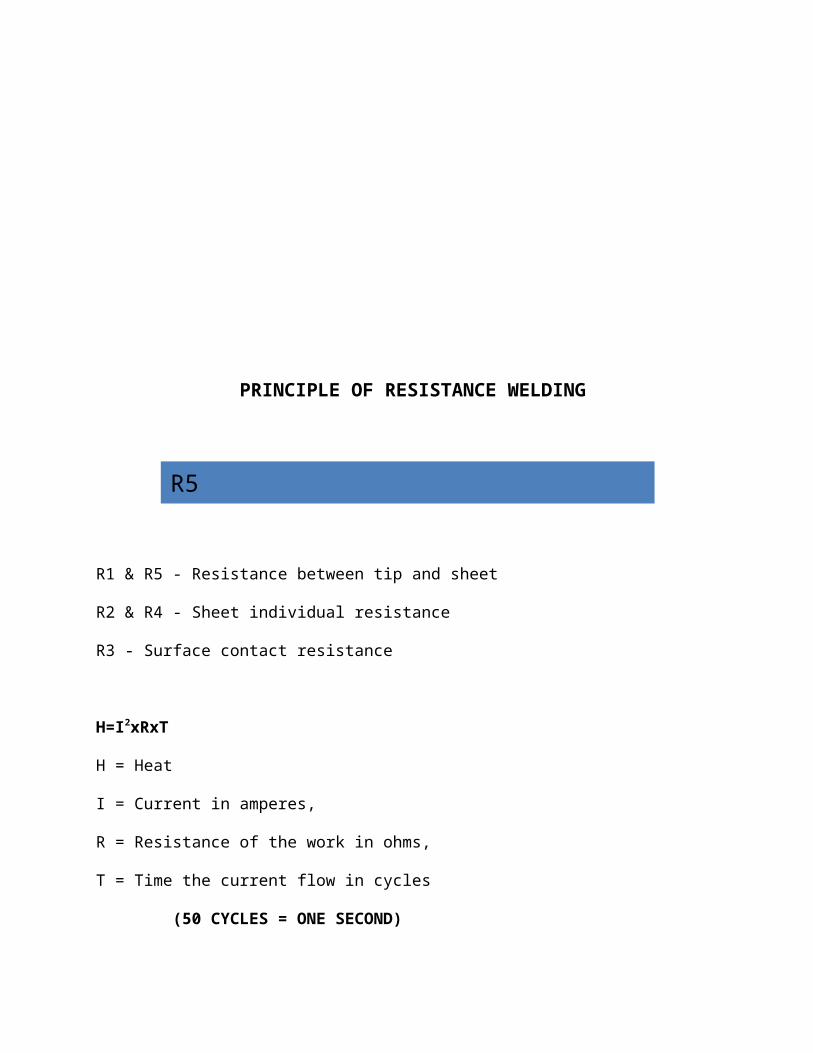
PRINCIPLE OF RESISTANCE WELDING
R1 & R5 - Resistance between tip and sheet
R2 & R4 - Sheet individual resistance
R3 - Surface contact resistance
H=I2xRxT
H = Heat
I = Current in amperes,
R = Resistance of the work in ohms,
T = Time the current flow in cycles
(50 CYCLES = ONE SECOND)
In welding it is desirable to have
• R1,R2,R4,R5 low
• R3 high
R1R2
R3
R4R5

Sequence of Resistance Welding
a). SQUEEZE TIME - Time required for the electrode to close on metal and apply proper pressure. It varies with the gap between the electrodes.
b). UP SLOPE TIME - Time taken for the current to reach from zero the set value.
c). WELD TIME - Time for current flow in object.
SQUEEZEWELDDown
SLOPEHOLD
OFF
d). DOWN SLOPE TIME - Time taken for the current to come down from set current to zero.
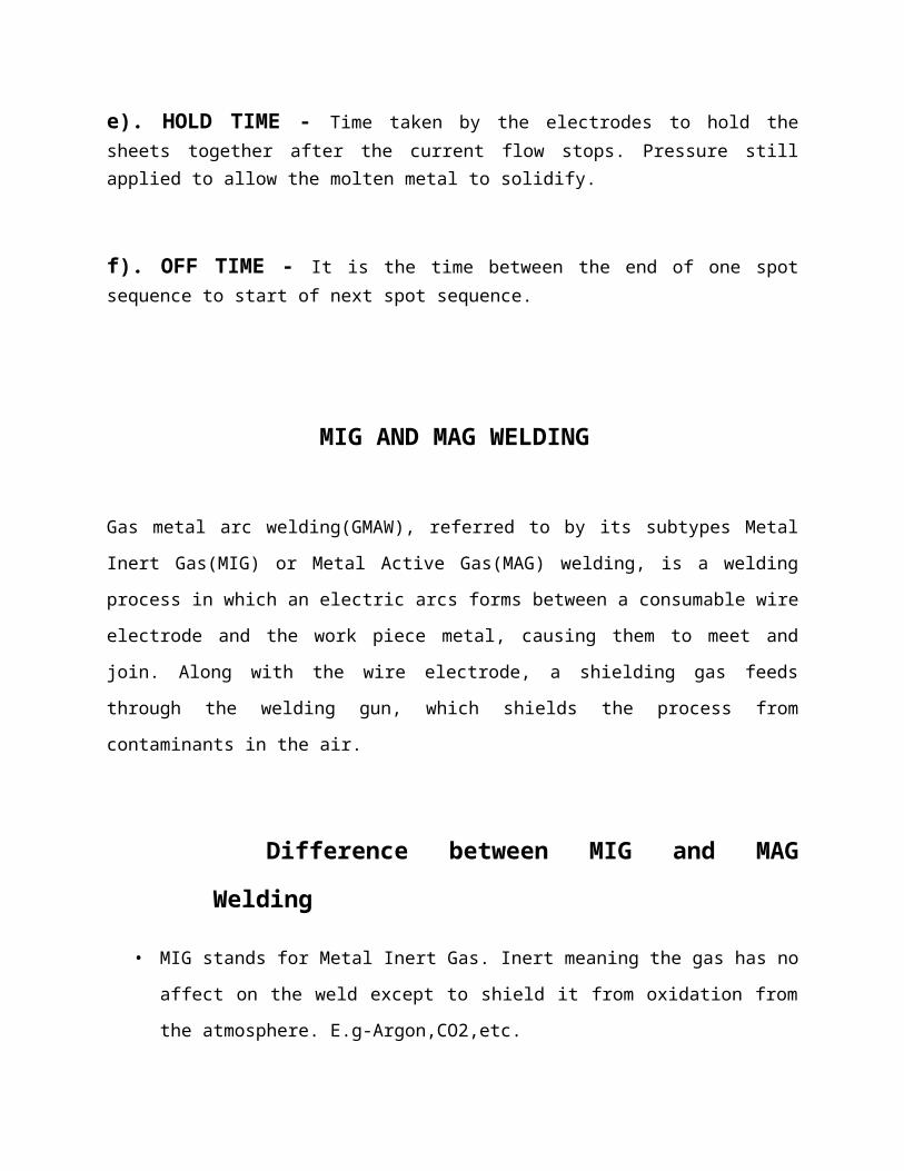
e). HOLD TIME - Time taken by the electrodes to hold the sheets together after the current flow stops. Pressure still applied to allow the molten metal to solidify.
f). OFF TIME - It is the time between the end of one spot sequence to start of next spot sequence.
MIG AND MAG WELDING
Gas metal arc welding(GMAW), referred to by its subtypes Metal Inert Gas(MIG) or Metal
Active Gas(MAG) welding, is a welding process in which an electric arcs forms between a
consumable wire electrode and the work piece metal, causing them to meet and join. Along with
the wire electrode, a shielding gas feeds through the welding gun, which shields the process from
contaminants in the air.
Difference between MIG and MAG Welding
• MIG stands for Metal Inert Gas. Inert meaning the gas has no affect on the weld except to
shield it from oxidation from the atmosphere. E.g-Argon,CO2,etc.
• MAG stands for Metal Active Gas. This would be a gas like oxygen that is reactive to the
arc and affects the temperature and other characteristics of weld and performs a function
besides just shielding. E.g.- Oxygen,Helium,etc.
WELDING DEFECTS
Excess Penetration - Burning through is more of a problem with thin sheet as a
higher level of skill is needed to balance heat input and torch traverse when welding thin
material.
Porosity - This occurs when gases are trapped in the solidifying weld metal. These may
arise from damp metal or from dirt.
Inclusions - These can occur when several runs are made along a V-join when joining
thick plate using flux cored and the slag covering a run is not totally removed after every
run before the following run.
Cracking - This can occur due just to thermal shrinkage or due to combination of strain
accompanying phase change and thermal shrinkage. A combination of poor design and
inappropriate may result in cracking.
Lack of Fusion - This is one of the most serious weld defect. It produces the notch
effect. In welds, incompletely fused spots are called lack of fusion.
EXHAUST SYSTEM IN JBM
OVERVIEW
Maruti 800,Alto and Omni are the 3 car models whose exhaust systems are made in the
plant and only for omni cars exhaust system contains catalyser.
Between catalyser and muffler there is a hole in pipe for sensor which determines the
amount of pollutants coming out of the exhaust pipe.
FUNCTIONS OF EXHAUST SYSTEM IN A CAR
1. To reduce the velocity of exhaust gases coming out from engine using pipes.
2. To reduce noise .
3. To reduce exhaust gases temperature .
4. To reduce the harmful pollutants from escaping into atmosphere using catalyser.

EXHAUST SYSTEM MAKING IN JBM CONSISTS OF FOLLOWING STEPS:-
1. Rolling and spot welding of metal sheets on DC1 (double coiling) machine.
2. Flanging operation on flanging machine (FFC1) in which both corners of cylindrical
shape are bent at right angle outward.
3. Fitting baffle after flanging on baffle fitting machine (BPC-1)by applying pressure
from upper side.
4. Covers on both the sides are attached by spot welding on (SMC-2) machine.
5. (CSC-1) machine is used for curling and seaming. for this two rollers are used
a. Right side roller is used for curling
b. Left side roller is used for seaming
6. (AWC-1) machine is used to attach engine side rod to the muffler, using MIG
welding.
7. (AWC-2) machine is used to attach other side rod to the muffler, using MIG welding.
8. Pressure check is done by sealing it from both sides and then dipping into water, if
bubbles do not come the piece is ok.
9. After welding the rods the leakage testing is done using (LTC-1), for which a gas is
filled into the exhaust system and pressure is checked for next 15 seconds ,if pressure
is constant throughout the piece is ok.
MUFFLER
Mufflers are installed within the exhaust system of most internal combustion engines, although
the muffler is not designed to serve any primary exhaust function. The muffler is engineered as
an acoustic soundproofing device designed to reduce the loudness of the sound pressure created
by the engine by way of Acoustic quieting. The majority of the sound pressure produced by the
engine is emanated out of the vehicle using the same piping used by the silent exhaust gases
absorbed by a series of passages and chambers lined with roving fiberglass insulation and/or
resonating chambers harmonically tuned to cause destructive interference wherein opposite
sound waves cancel each other out. An unavoidable side effect of muffler use is an increase of
back pressure which decreases engine efficiency. This is because the engine exhaust must share
the same complex exit pathway built inside the muffler as the sound pressure that the muffler is
designed to mitigate.
An exhaust pipe must be carefully designed to carry toxic and/or noxious gases away from the
users of the machine. Indoor generators and furnaces can quickly fill an enclosed space with
carbon monoxide or other poisonous exhaust gases if they are not properly vented to the
outdoors. Also, the gases from most types of machine are very hot; the pipe must be heat-
resistant, and it must not pass through or near anything that can burn or can be damaged by heat.
A chimney serves as an exhaust pipe in a stationary structure. For the internal combustion engine
it is important to have the exhaust system "tuned" (refer to tuned pipe) for optimal efficiency.
Also this should meet the regulation norms maintained in each country.

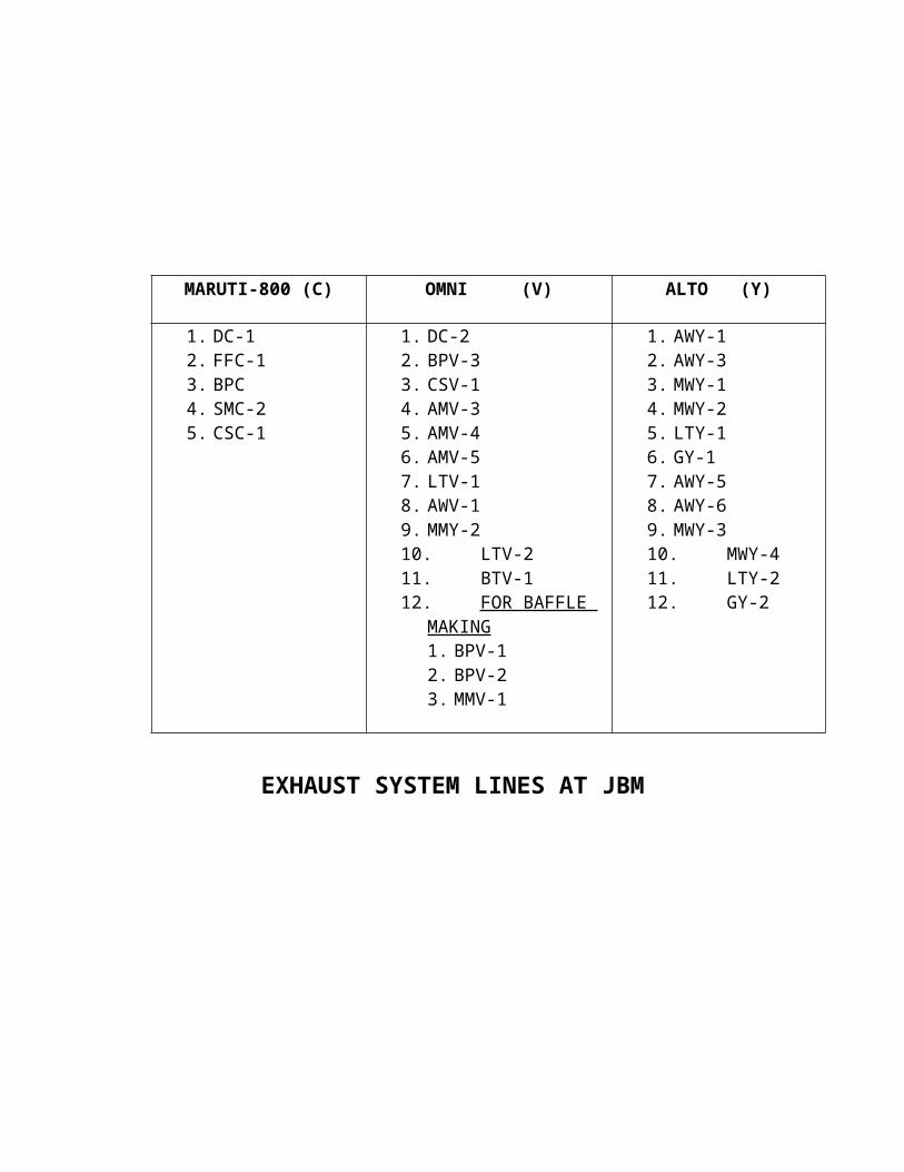
EXHAUST SYSTEM LINES AT JBM
MARUTI-800 (C) OMNI (V) ALTO (Y)
1. DC-12. FFC-13. BPC4. SMC-25. CSC-1
1. DC-22. BPV-33. CSV-14. AMV-35. AMV-46. AMV-57. LTV-18. AWV-19. MMY-210. LTV-211. BTV-112. FOR BAFFLE
MAKING1. BPV-12. BPV-23. MMV-1
1. AWY-12. AWY-33. MWY-14. MWY-25. LTY-16. GY-17. AWY-58. AWY-69. MWY-310. MWY-411. LTY-212. GY-2
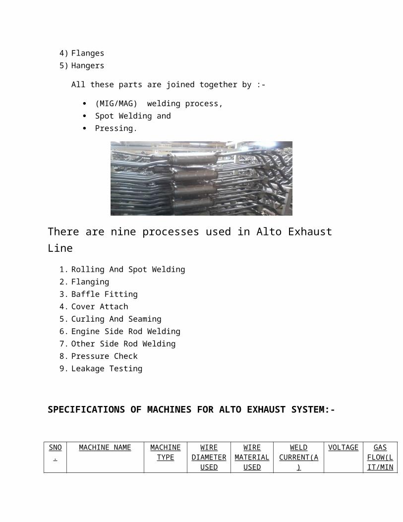
ALTO EXHAUST SYSTEM
ALTO EXHAUST SYSTEM CONSISTS OF FOLLOWING PARTS:-
1) Muffler Box2) Baffles3) Pipes4) Flanges5) Hangers
All these parts are joined together by :-
(MIG/MAG) welding process, Spot Welding and Pressing.
There are nine processes used in Alto Exhaust Line
1. Rolling And Spot Welding2. Flanging3. Baffle Fitting4. Cover Attach5. Curling And Seaming6. Engine Side Rod Welding7. Other Side Rod Welding8. Pressure Check9. Leakage Testing
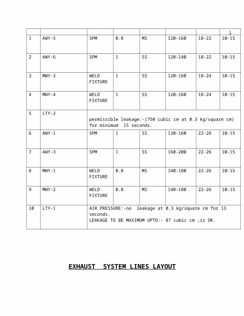
SPECIFICATIONS OF MACHINES FOR ALTO EXHAUST SYSTEM:-
SNO. MACHINE NAME MACHINE TYPE
WIRE DIAMETER
USED
WIRE MATERIAL
USED
WELD CURRENT(A)
VOLTAGE GAS FLOW(LIT/MIN)
1 AWY-5 SPM 0.8 MS 120-160 18-22 10-15
2 AWY-6 SPM 1 SS 120-140 18-22 10-15
3 MWY-3 WELD FIXTURE
1 SS 120-160 18-24 10-15
4 MWY-4 WELD FIXTURE
1 SS 120-160 18-24 10-15
5 LTY-2permissible leakage:-(750 cubic cm at 0.3 kg/square cm) for minimum 15 seconds.
6 AWY-1 SPM 1 SS 120-160 22-26 10-15
7 AWY-3 SPM 1 SS 160-200 22-26 10-15
8 MWY-1 WELD FIXTURE
0.8 MS 140-180 22-26 10-15
9 MWY-2 WELD FIXTURE
0.8 MS 140-180 22-26 10-15
10 LTY-1 AIR PRESSURE:-no leakage at 0.3 kg/square cm for 13 seconds.LEAKAGE TO BE MAXIMUM UPTO:- 87 cubic cm ,is OK.
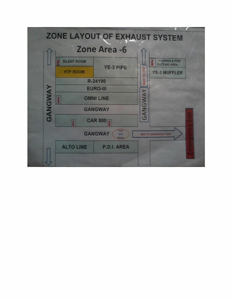
EXHAUST SYSTEM LINES LAYOUT
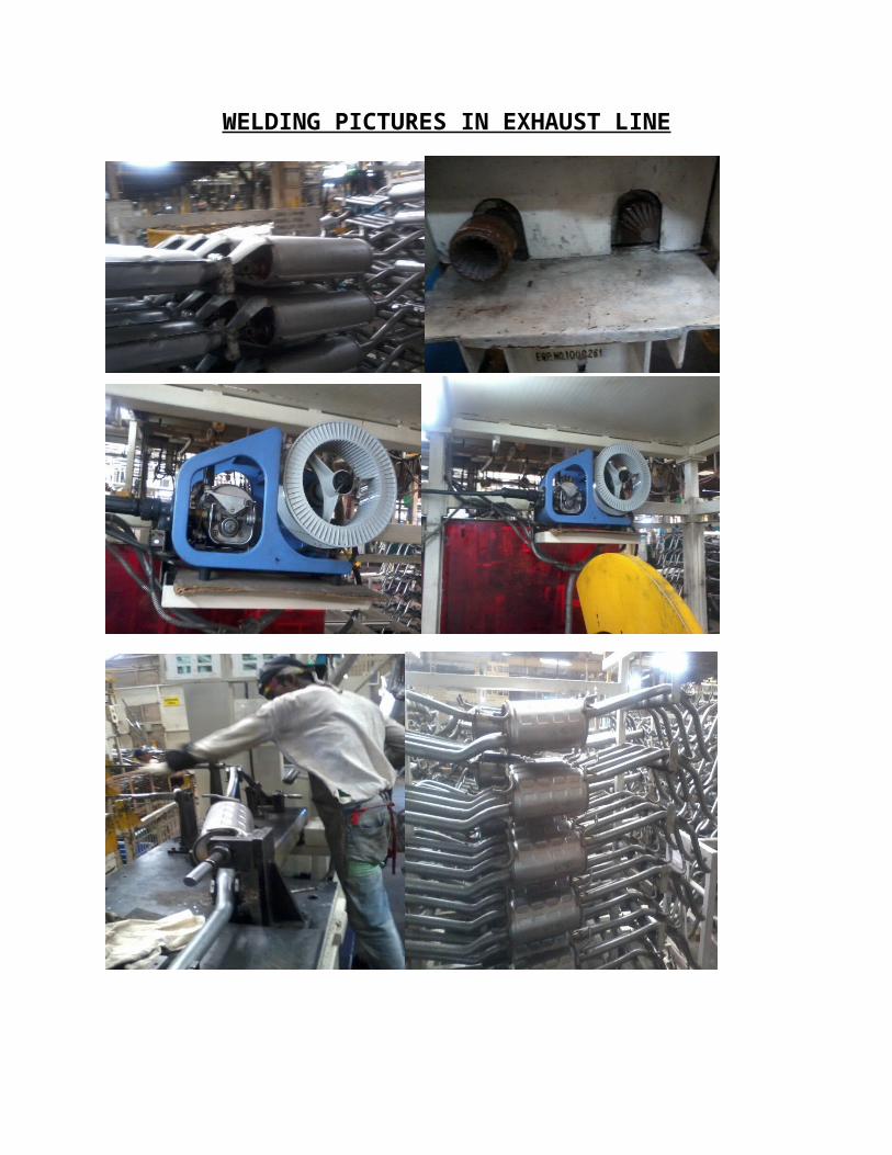
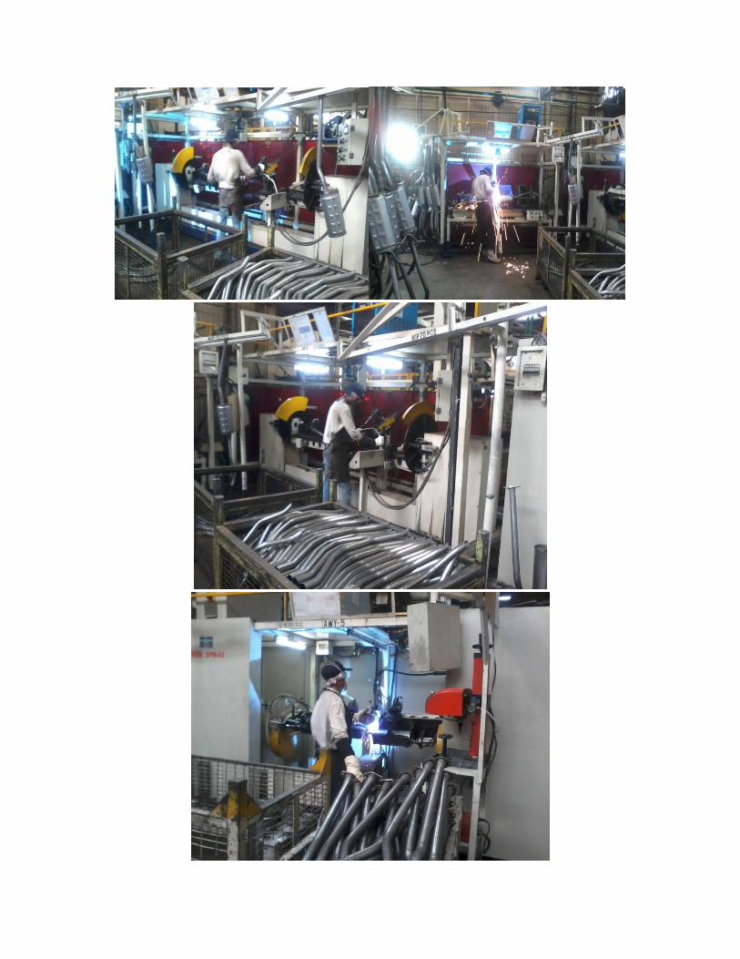
WELDING PICTURES IN EXHAUST LINE
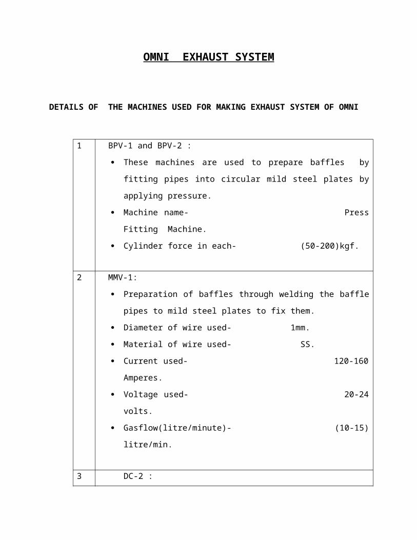
OMNI EXHAUST SYSTEM
DETAILS OF THE MACHINES USED FOR MAKING EXHAUST SYSTEM OF OMNI
1 BPV-1 and BPV-2 :
These machines are used to prepare baffles by fitting pipes into circular
mild steel plates by applying pressure.
Machine name- Press Fitting Machine.
Cylinder force in each- (50-200)kgf.
2 MMV-1:
Preparation of baffles through welding the baffle pipes to mild steel plates
to fix them.
Diameter of wire used- 1mm.
Material of wire used- SS.
Current used- 120-160 Amperes.
Voltage used- 20-24 volts.
Gasflow(litre/minute)- (10-15) litre/min.
3 DC-2 :
Mild steel Sheets are rolled and then spot welded on 10 spots on double
coiling machine.
It also consists of a sheet lifter which automatically lift and move it to
roller where it is rolled.
Pressure in mpa when m/c not lifting the sheets -0.3
Pressure in mpa when m/c is lifting the sheets -0.6
4 BPV-3:
Baffles are fitted into covers (mufflers) using pressure.

Machine name – Press Fitting Machine.
Cylinder force- (50-200) Kgf.
5 CSV_1:
Machine name - Curling And Seaming Machine.
Curling and seaming of both ends of muffler is done after putting lids on
them.
Curling width - ( 9.1 - 0.5)mm
Length of pipe from end plate- ( 0.5~1.5) mm
6 AWV-3:
Flange is welded on pipe which is fitted to catalyser on AWV-4
Machine name- SPM
Diameter of wire used- 1mm
Material of wire used- SS
Current used- 120-160amperes
Voltage used- 20-24 volts
Gasflow(litre/minute)- 10-15litre/min
7 AWV-4:
Pipe is fitted on 1 side of catalyser.
Machine name/type - SPM
Diameter of wire used- 1mm
Material of wire used- SS
Current used- 120-160amperes
Voltage used- 20-24 volts
Gasflow(litre/minute)- 10-15litre/min
8 AWV-5:
pipe is fitted on another side of catalyser.
Machine name/type - SPM
Diameter of wire used- 1mm
Material of wire used- SS
Current used- 120-160amperes
Voltage used- 20-24 volts
Gasflow(litre/minute)- 10-15litre/min
9 LTV-1:
Leakage test of product prepared on AWV-5 is done.
10
AWV-1:
catalyser and box are joined together using welding process.
Diameter of wire used- 1mm
Material of wire used- SS
Current used- 120-160amperes
Voltage used- 18-24 volts
Gasflow(litre/minute)- 10-15litre/min
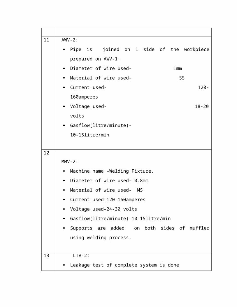
11 AWV-2:
Pipe is joined on 1 side of the workpiece prepared on AWV-1.
Diameter of wire used- 1mm
Material of wire used- SS
Current used- 120-160amperes
Voltage used- 18-20 volts
Gasflow(litre/minute)- 10-15litre/min
12
MMV-2:
Machine name –Welding Fixture.
Diameter of wire used- 0.8mm
Material of wire used- MS
Current used-120-160amperes
Voltage used-24-30 volts
Gasflow(litre/minute)-10-15litre/min
Supports are added on both sides of muffler using welding process.
13 LTV-2:
Leakage test of complete system is done
14 BTV-1:
Cover is added on catalyser using bolts using drill to avoid heat
dissipation .
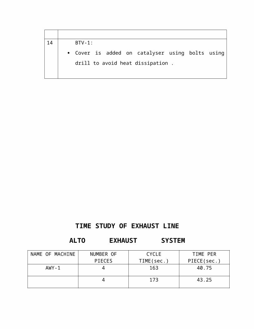
TIME STUDY OF EXHAUST LINE
ALTO EXHAUST SYSTEM
NAME OF MACHINE
NUMBER OF PIECES
CYCLE TIME(sec.) TIME PER PIECE(sec.)
AWY-1 4 163 40.75
4 173 43.25
AWY-3 4 192 48
4 162 40.5
MWY-1 4 152 38
4 146 36.5
MWY-2 4 110 27.5
4 152 38
LTY-1 4 106 26.5
4 111 27.75
GY-1 4 74 18.5
4 72 18
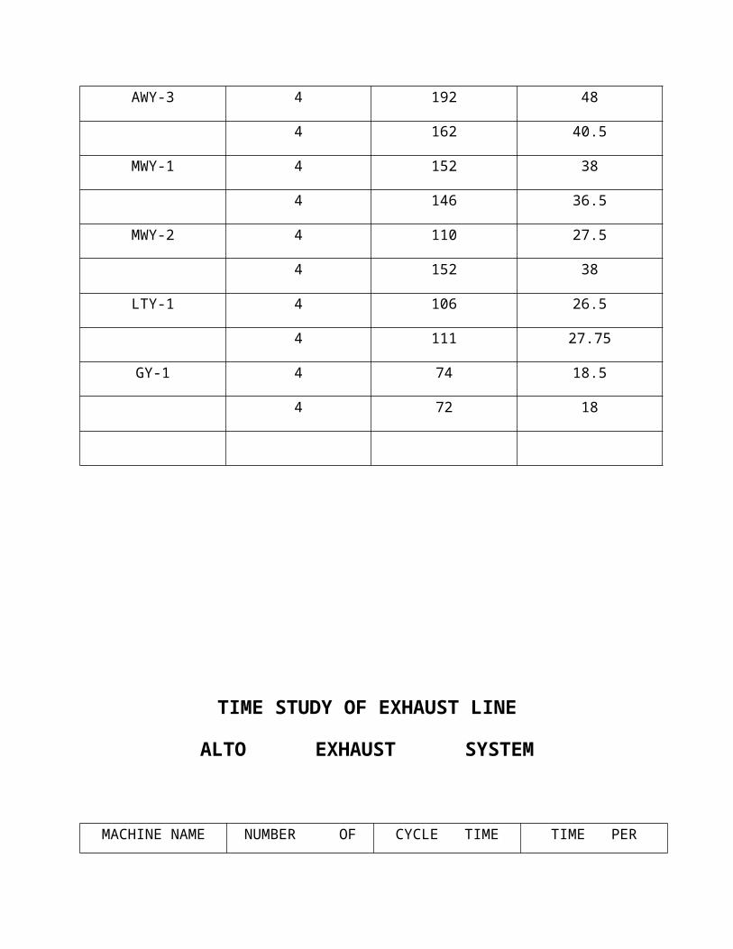
TIME STUDY OF EXHAUST LINE
ALTO EXHAUST SYSTEM
MACHINE NAME NUMBER OF PIECES
CYCLE TIME (IN SECONDS)
TIME PER PIECE ( IN SECONDS)
AWY-5 4 217 54.25
4 221 55.25
AWY-6 4 172 43
4 164 41
MWY-1 4 154 38.5
4 204 51
MWY-4 4 256 64
4 217 54.25
LTY-2 4 320 80
4 306 76.5
GY-2 4 102 25.5
4 106 26.5
TIME STUDY OF EXHAUST LINE
MARUTI 800 EXHAUST SYSTEM
MACHINE NAME NUMBER OF PIECES
TIME TAKEN(sec.) TIME PER PIECE(sec.)
DC-1 4 120 30
FFC-1 4 47 11.75
BPC 4 62 15.5
SMC-2 4 36 9
CSC-1 4 255 63.75
TIME STUDY OF OMNI EXHAUST SYSTEM
MACHINE NAME NUMBER OF TIME TAKEN(sec.) TIME PER
PIECES PIECE(sec.)
MMV-1 4 112 28
DC-2 4 218 54.5
BPV-3 4 185 46.25
CSV-1 4 221 55.25
AWV-4 4 152 38
AWV-1 4 230 57.5
AWV-2 4 207 51.75
MMV-2 4 282 70.5
LTV-2 4 276 69
BTV-1 4 148 37
DC-2 4 218 54.5
BPV-3 4 185 46.25
WELDING
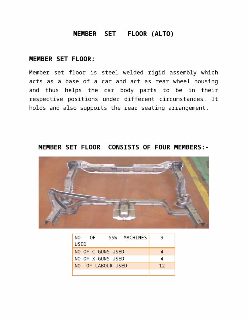
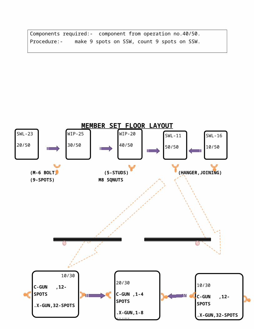
MEMBER SET FLOOR (ALTO)

MEMBER SET FLOOR:
Member set floor is steel welded rigid assembly which acts as a base of a car and act as rear wheel housing and thus helps the car body parts to be in their respective positions under different circumstances. It holds and also supports the rear seating arrangement.
MEMBER SET FLOOR CONSISTS OF FOUR MEMBERS:-
NO. OF SSW MACHINES USED 9NO.OF C-GUNS USED 4NO.OF X-GUNS USED 4NO. OF LABOUR USED 12
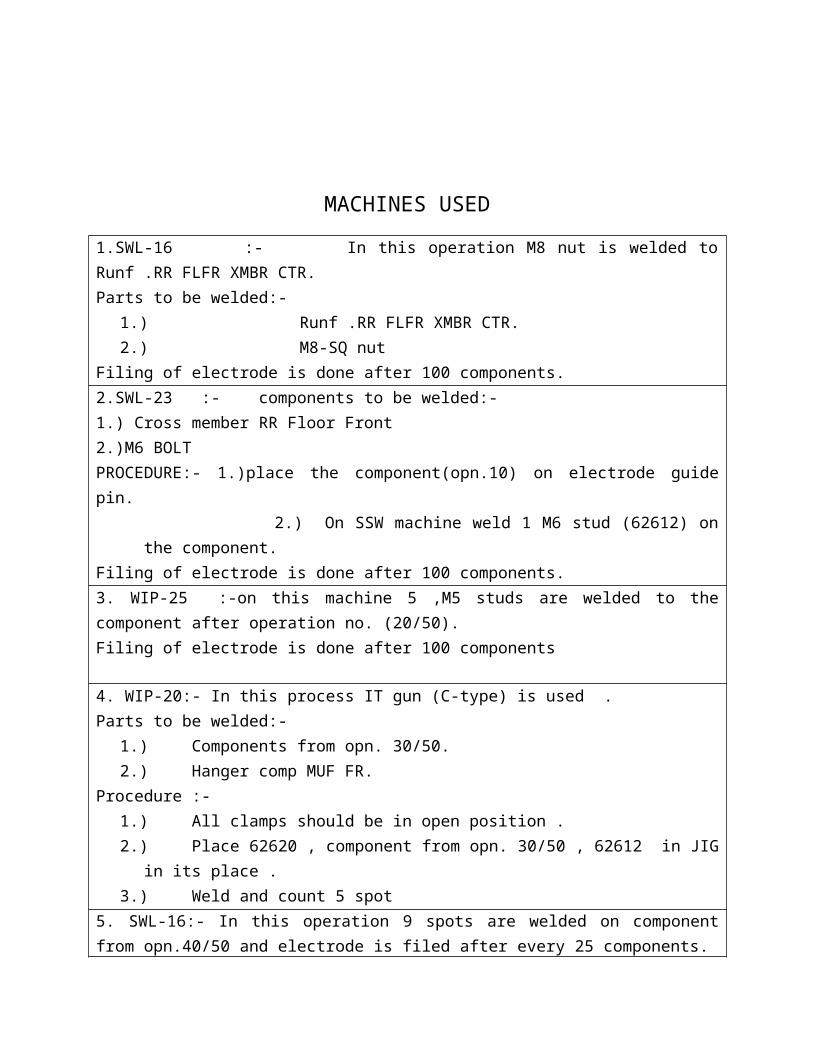
MACHINES USED
1.SWL-16 :- In this operation M8 nut is welded to Runf .RR FLFR XMBR CTR.Parts to be welded:-
1.) Runf .RR FLFR XMBR CTR.

2.) M8-SQ nutFiling of electrode is done after 100 components.2.SWL-23 :- components to be welded:-1.) Cross member RR Floor Front2.)M6 BOLTPROCEDURE:- 1.)place the component(opn.10) on electrode guide pin.
2.) On SSW machine weld 1 M6 stud (62612) on the component.Filing of electrode is done after 100 components.3. WIP-25 :-on this machine 5 ,M5 studs are welded to the component after operation no. (20/50).Filing of electrode is done after 100 components
4. WIP-20:- In this process IT gun (C-type) is used .Parts to be welded:-
1.) Components from opn. 30/50.2.) Hanger comp MUF FR.
Procedure :-1.) All clamps should be in open position .2.) Place 62620 , component from opn. 30/50 , 62612 in JIG in its place .3.) Weld and count 5 spot
5. SWL-16:- In this operation 9 spots are welded on component from opn.40/50 and electrode is filed after every 25 components.Components required:- component from operation no.40/50.Procedure:- make 9 spots on SSW, count 9 spots on SSW.
MEMBER SET FLOOR LAYOUTSWL-23
20/50
WIP-25
30/50
WIP-20
40/50
SWL-11
50/50
SWL-16
10/50

(M-6 BOLT) (5-STUDS) (HANGER,JOINING) (9-SPOTS) M8 SQNUTS
C-GUN X-GUN C-GUN X-GUN C-GUN X-GUN
C-GUN X-GUN
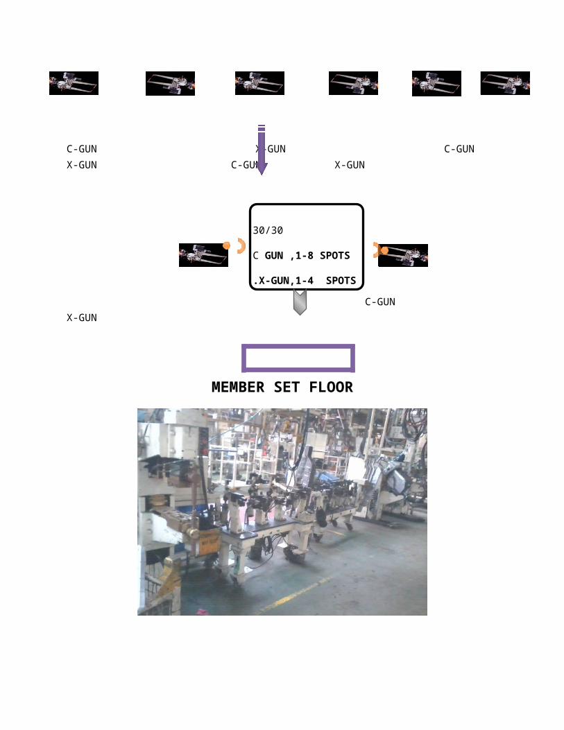
MEMBER SET FLOOR
10/30
C-GUN ,12-SPOTS
.X-GUN,32-SPOTS
20/30
C-GUN ,1-4 SPOTS
.X-GUN,1-8 SPOTS
10/30
C-GUN ,12-SPOTS
.X-GUN,32-SPOTS
30/30
C GUN ,1-8 SPOTS
.X-GUN,1-4 SPOTS
TROLLEY
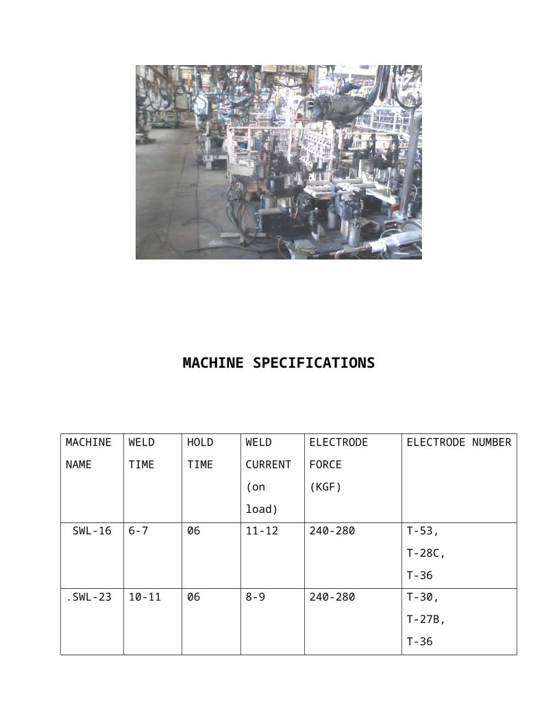
MACHINE SPECIFICATIONS
MACHINE
NAME
WELD
TIME
HOLD
TIME
WELD
CURRENT
(on load)
ELECTRODE
FORCE
(KGF)
ELECTRODE
NUMBER
SWL-16 6-7 06 11-12 240-280 T-53,
T-28C,
T-36
.SWL-23 10-11 06 8-9 240-280 T-30,
T-27B,
T-36
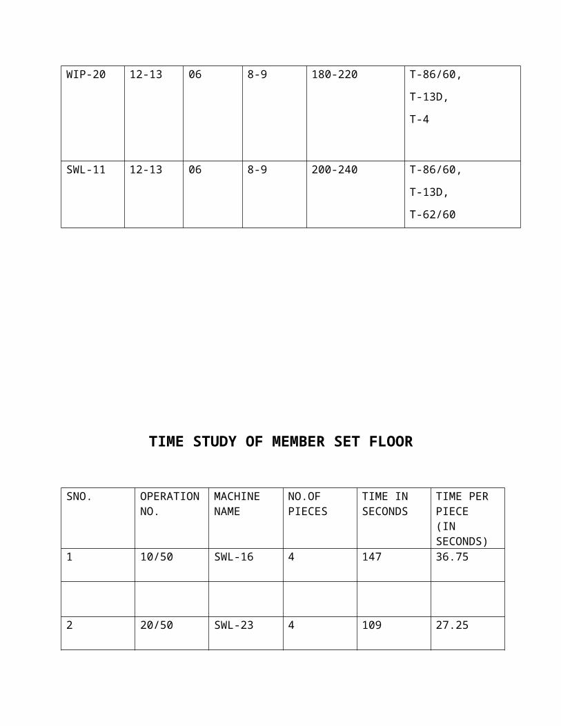
WIP-20 12-13 06 8-9 180-220 T-86/60,
T-13D,
T-4
SWL-11 12-13 06 8-9 200-240 T-86/60,
T-13D,
T-62/60
TIME STUDY OF MEMBER SET FLOOR
SNO. OPERATION MACHINE NO.OF TIME IN TIME PER
NO. NAME PIECES SECONDS PIECE(IN SECONDS)
1 10/50 SWL-16 4 147 36.75
2 20/50 SWL-23 4 109 27.25
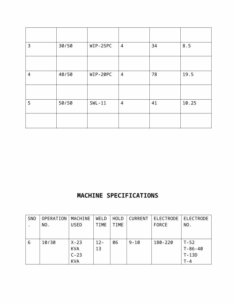
3 30/50 WIP-25PC 4 34 8.5
4 40/50 WIP-20PC 4 78 19.5
5 50/50 SWL-11 4 41 10.25
MACHINE SPECIFICATIONS
SNO.
OPERATION NO.
MACHINE USED
WELD TIME
HOLD TIME
CURRENT
ELECTRODE FORCE
ELECTRODE NO.
6 10/30 X-23 KVAC-23 KVA
12-13 06 9-10 180-220 T-52T-86-40T-13DT-4
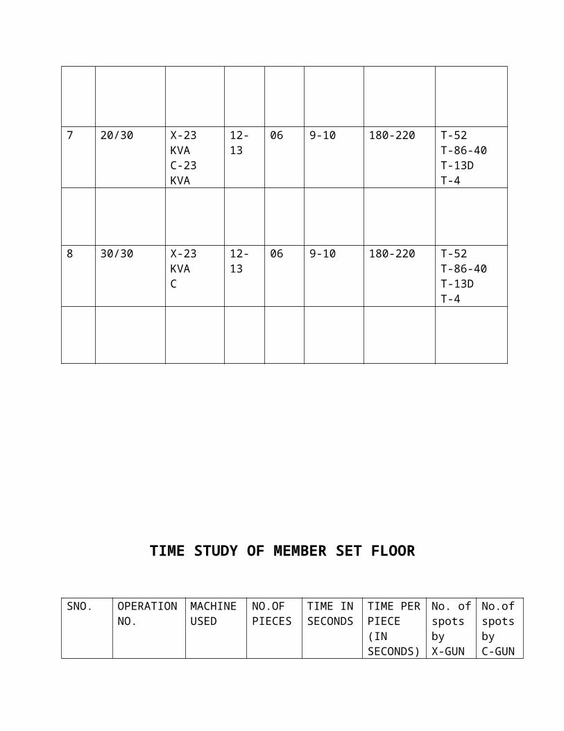
7 20/30 X-23 KVAC-23 KVA
12-13 06 9-10 180-220 T-52T-86-40T-13DT-4
8 30/30 X-23 KVAC
12-13 06 9-10 180-220 T-52T-86-40T-13DT-4
TIME STUDY OF MEMBER SET FLOOR

SNO. OPERATION NO.
MACHINE USED
NO.OF PIECES
TIME IN SECONDS
TIME PER PIECE(IN SECONDS)
No. of spots byX-GUN
No.of spots byC-GUN
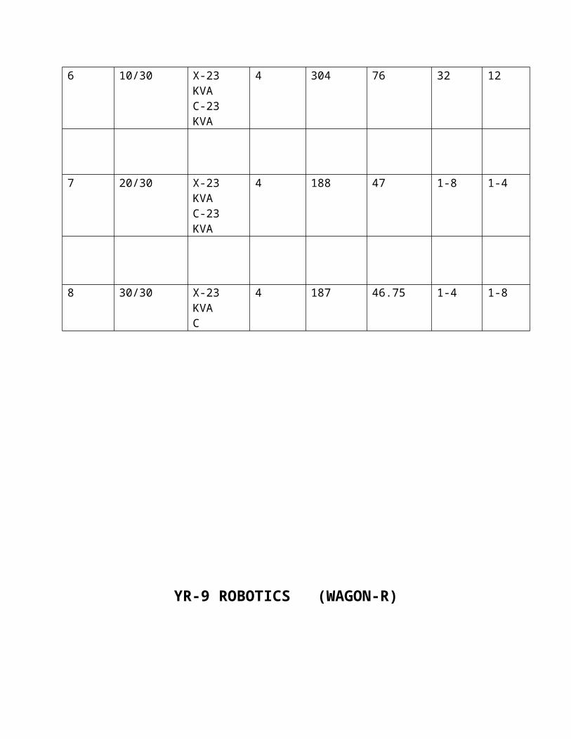
6 10/30 X-23 KVAC-23 KVA
4 304 76 32 12
7 20/30 X-23 KVAC-23 KVA
4 188 47 1-8 1-4
8 30/30 X-23 KVAC
4 187 46.75 1-4 1-8
YR-9 ROBOTICS (WAGON-R)

TO STUDY THE FOLLOWING:-
1. PARAMETER STUDY
2. TIME STUDY
3. NEW POSSIBLE INNOVATIONS
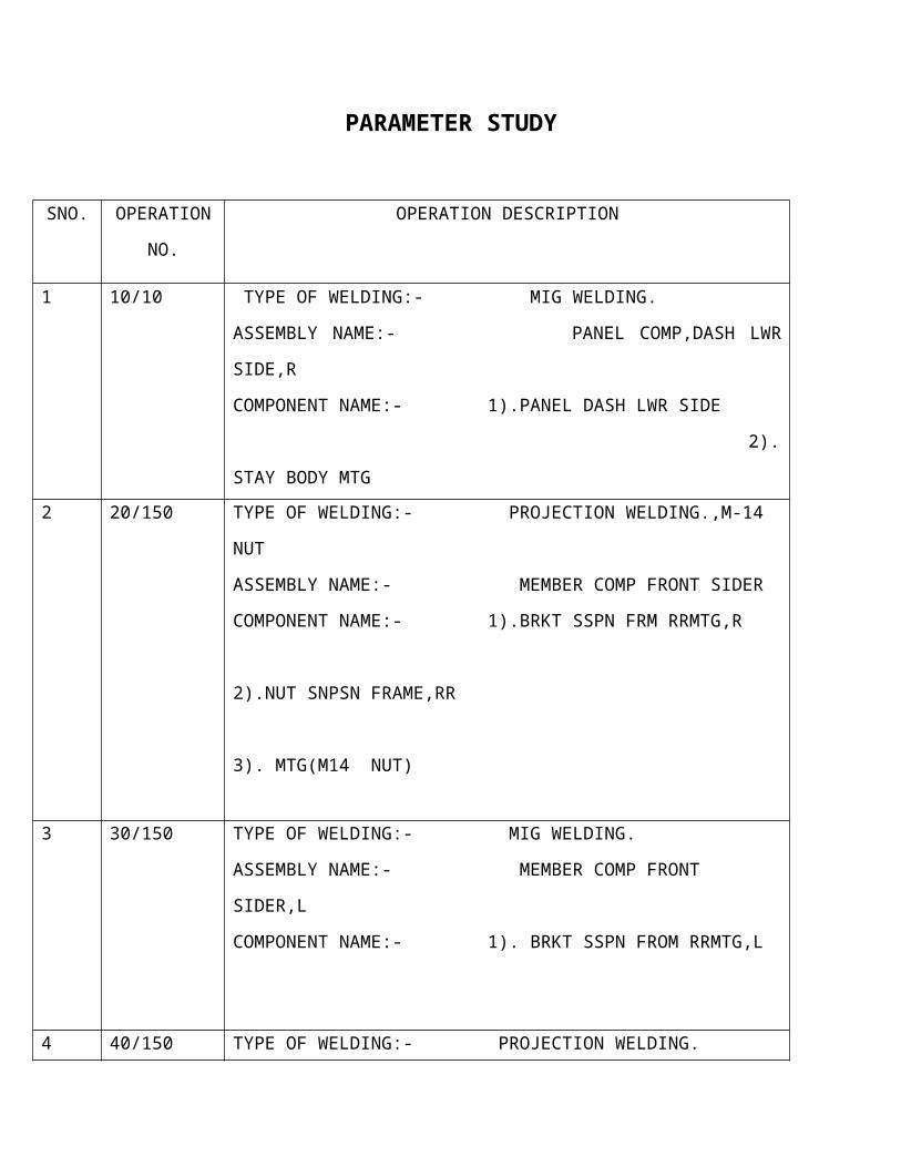
PARAMETER STUDY
SNO. OPERATION
NO.
OPERATION DESCRIPTION
1 10/10 TYPE OF WELDING:- MIG WELDING.
ASSEMBLY NAME:- PANEL COMP,DASH LWR SIDE,R
COMPONENT NAME:- 1).PANEL DASH LWR SIDE
2).STAY BODY MTG
2 20/150 TYPE OF WELDING:- PROJECTION WELDING.,M-14 NUT
ASSEMBLY NAME:- MEMBER COMP FRONT SIDER
COMPONENT NAME:- 1).BRKT SSPN FRM RRMTG,R
2).NUT SNPSN FRAME,RR
3). MTG(M14 NUT)
3 30/150 TYPE OF WELDING:- MIG WELDING.
ASSEMBLY NAME:- MEMBER COMP FRONT SIDER,L
COMPONENT NAME:- 1). BRKT SSPN FROM RRMTG,L
4 40/150 TYPE OF WELDING:- PROJECTION WELDING.
ASSEMBLY NAME:- MEMBER COMP DASH SIDE R AND L
COMPONENT NAME:- 1). MEMBER COMP DASH SIDE R AND L
2). NUT SNPSN FRAME,FRT MTG (M14
NUT)
5 50/150 TYPE OF WELDING:- MIG WELDING.
ASSEMBLY NAME:- MEMBER COMP DASH SIDE L
COMPONENT NAME:- 1). COMP. FROM OPERATION 40/150
6 60/150 TYPE OF WELDING:- SPOT WELDING. ,5 SPOTS
COMPONENT NAME:- 1). BRKT SSPN FRM RRMTG,L
2).EXT DASH LOWER SIDE L
FILE THE TIP AFTER 40 COMPONENTS
7 70/150 TYPE OF WELDING:- SPOT WELDING.
ASSEMBLY NAME:- MEMBER COMP FRONT SIDER,L
COMPONENT NAME:- 1). COMP. FROM OPERATION 10
2).MEMBER DASH SIDE ,L
8 80/150 TYPE OF WELDING:- SPOT WELDING.(FIXED TYPE )
ASSEMBLY NAME:- MEMBER COMP FRONT SIDER,R
COMPONENT NAME:- 1). COMP. FROM OPERATION 70
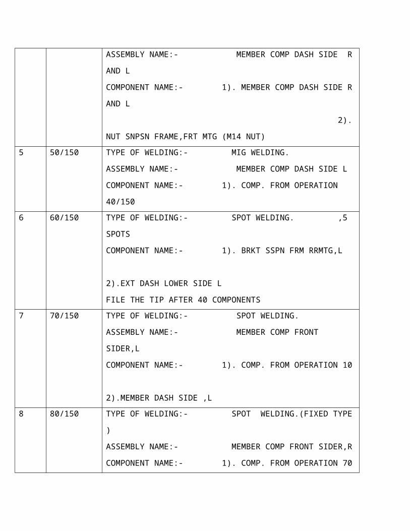
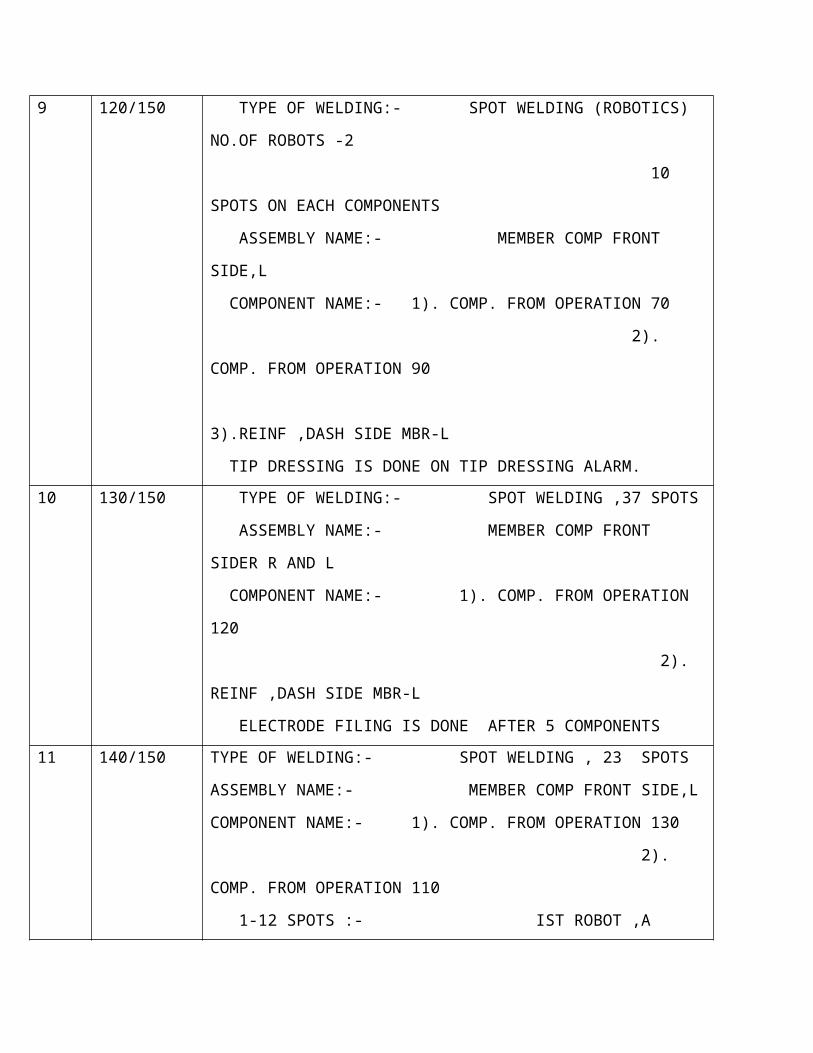
9 120/150 TYPE OF WELDING:- SPOT WELDING (ROBOTICS) NO.OF
ROBOTS -2
10 SPOTS ON EACH COMPONENTS
ASSEMBLY NAME:- MEMBER COMP FRONT SIDE,L
COMPONENT NAME:- 1). COMP. FROM OPERATION 70
2). COMP. FROM OPERATION 90
3).REINF ,DASH SIDE MBR-L
TIP DRESSING IS DONE ON TIP DRESSING ALARM.
10 130/150 TYPE OF WELDING:- SPOT WELDING ,37 SPOTS
ASSEMBLY NAME:- MEMBER COMP FRONT SIDER R AND L
COMPONENT NAME:- 1). COMP. FROM OPERATION 120
2). REINF ,DASH SIDE MBR-L
ELECTRODE FILING IS DONE AFTER 5 COMPONENTS
11 140/150 TYPE OF WELDING:- SPOT WELDING , 23 SPOTS
ASSEMBLY NAME:- MEMBER COMP FRONT SIDE,L
COMPONENT NAME:- 1). COMP. FROM OPERATION 130
2). COMP. FROM OPERATION 110
1-12 SPOTS :- IST ROBOT ,A
13-23 SPOTS:- 2ND ROBOT ,B
TIP CHANGING IS DONE ON CHANGING TIP ALARM.
12 150/150 TYPE OF WELDING:- SPOT AND MIG WELDING
ASSEMBLY NAME:- MEMBER COMP FRONT SIDER R AND L
OPERATIONS:-
1).19 SPOTS ON EACH COMPONENT
2).PLUG WELDING ON 4 PLACES
3).10mm MIG WELDING ON 1 SPOT.
COMPONENT NAME:- 1). COMP. FROM OPERATION 140
FILING IS DONE AFTER 15 COMPONENTS
PARAMETER STUDY OF YR-9
SNO. OPERATION NO.
WELD TIME
(CYCLES)
HOLD TIME (SECONDS)
WELD CURRENT
(KA)
ELECTRODE FORCE (KGF)
SLOPETIME
ELECTRODE NO.
1 20/150 18-20 25 16.5-17.5 530-570 2-3 T 332T 333
2 40/150 18-20 25 16.5-17.5 530-570 2-3 T 332T 333
3 60/150 13-14 10 10.5-11.5 180-220 2-3 T 331T62/50
T95 ,T23
4 70/150 13-14 10 10.5-11.5 240-300 2-3 T 331T62/60
T95 ,T23
5 80/150 18-20 25 10.5-11.5 240-300 2-3 T 13-D T -95
6 120/150 14-15 5 10.5-11.5 3000-3500 2-3 T 325T334 , T16D
7 130/150 13-14 10 10.5-11.5 240-300 2-3 T 331, T62/50, T 95
8 140/150 14-15 5 10.5-11.5 3000-3500 2-3 T 325T334 , T16D
9 150/150 13-14 10 10.5-11.5 240-300 2-3 T 331, T62/50,
T 95
PARAMETER STUDY OF YR-9
SNO. MACHINE NAME
OPERATION NO.
WIRE DIAMETER
WELD CURRENT
VOLTAGE GAS FLOW
WIRE MATERIAL
1 MIG WELDING MACHINE
10/10 0.8 130-180 20-35 15-25 MS
2 MIG WELDING MACHINE
30/150 0.8 100-130 25-30 20-25 MS
3 MIG WELDING MACHINE
50/150 0.8 100-130 25-30 20-25 MS
4 MIG WELDING MACHINE
150/150 0.8 100-130 25-30 20-25 MS
TIME STUDY OF YR-9
SNO. OPERATION NO. MACHINE NAME TIME FOR 5 PIECES IN SECONDS
TIME FOR 1 COMPONENT IN SECONDS
1 10/10 MIG WELDING MACHINE
180 36
2 20/150 SSW 48 9.6
3 30/150 MIG WELDING MACHINE
61 12.2
4 40/150 SSW
5 50/150 MIG WELDING MACHINE
360 72
6 60/150 IT GUN C TYPE 128 25.6
7 70/150 IT GUN C TYPE 395 79
8 80/150 IT GUN126 308 61.6
9 120/150 IT GUN X TYPE 163 32.6
10 130/150 IT GUN C TYPE 365 73
11 140/150 SPOT WELDING 193 38.6
12 150/150 MIG WELDING MACHINE
368 73.6
IMPROVEMENT SUGGESTED
LINE NAME –YR9 (WAGON R)
Operation number-150/150
Current situation- worker has to move a longer distance so fatigue is more.
Improved Situation:- Worker’s moving distance is reduced so he will have lesser fatigue.
IMPROVED SITUATION
FIXTURE 1 FIXTURE 2
CURRENT SITUATION
Fixture 2Fixture 1
LINE NAME :- YE-3 LINE
TIP DRESSING OF ROBOTS ON WELDING LINE
On Robotics Line Tip Dressing Is Done Automatically By The Robots After Making Certain Number Of Spots.
Each Robot Has Been Programmed Such That It Do Dressing After Different Number Of Spots According To The Requirements.
THIS TABLE SHOWS AFTER HOW MANY SPOTS EACH ROBOT DO ITS TIP DRESSING
SNO. NAME OF ROBOT NUMBER OF SPOTS AFTER
WHICH DRESSING OF TIP IS
DONE
1 RYE-1 266
2 RYE-2 174
3 RYE-3 204
4 RYE-4 221
5 RYE-5 206
6 RYE-6 194
7 RYE-7 205
8 RYE-8 202
9 RYE-9 154
10 RYE-10 204
11 RYE-11 133

YL-8(ERTIGA) TIME STUDY
ROBOT NAME - WHL
COMPONENT NAME-PANEL COMPONENT WHEEL HOUSE INNER LEFT
SNO. OPERATION NUMBER
40/80
OPERATION NUMBER
50/80
OPERATION NUMBER
60/80
OPERATION NUMBER
70/801 27 25 59 48
2 28 25 54 48
3 28 25 55 48
4 29 25 54 46
5 28 25 55 48
6 29 26 78 55
7 29 24 54 48
8 28 25 54 49
9 28 26 54 48
10 29 26 54 48
AVERAGE TIMINGS
(Sec.)
2.27 25.25 57.1 48.6
YL-8(ERTIGA) TIME STUDY
ROBOT NAME - WHR
COMPONENT NAME-PANEL COMPONENT WHEEL HOUSE INNER RIGHT
SNO. OPERATION
NUMBER
40/80
OPERATION
NUMBER
50/80
OPERATION
NUMBER
60/80
OPERATION
NUMBER
70/80
1 36 26 53 65
2 38 27 53 57
3 36 26 52 56
4 35 27 53 56
5 35 26 53 56
6 36 27 58 56
7 36 26 54 56
8 36 26 54 55
9 36 27 53 64
10 37 32 56 56
AVERAGE
TIMINGS (Sec.)
35.8 27 53.9 56.8
CONCLUSION
JAY BHARAT MARUTI LTD is a world class company in sheet metal technology. Training
here has been very useful in understanding the working environment of the company, relation
between officers and their subordinates, shop floor, organizational value of any industry and
many other things. How people work together and achieve mass production in any industry in
prescribed time with quality. I came to know about various processes and activities done to
develop and produce the components effectively and accurately.
I saw and learn, how the latest machineries like CNC, WELDING ROBOTS etc. save the time
and improve the accuracy and increases the production. The industrial training is very beneficial
to me. After the training, I got the practical knowledge about machines and machine process &
also knows how these machines are used for making different kind of equipment, machines and
products.
I finally thanks to Mr. NIKHIL VERMA , Mr. ROHAN SIR and Mr. TARUN BHATIA SIR for
guiding me throughout the training and encouraging me to learn about the industrial
environment.
REFERENCES
a. Mr. Ranvijay Singh
Head Of Department (Mechanical)
E-mail- [email protected]
b. Nikhil Verma
Head Of Welding (Jay Bharat Maruti)
Contact No. - +91- 9953864924