trajectory planning, optimization and control of a hybrid ... · trajectory planning, optimization...
TRANSCRIPT

Trajectory Planning, Optimization and Control of a Hybrid Mechanical Press
KAI HE1, YUANXIN LUO2, CHING TOM KONG2, R. DU2
1Shenzhen Institute of Advanced Technology, Chinese Academy of Sciences Shenzhen 518067, P.R. CHINA
2Institute of Precision Engineering, The Chinese University of Hong Kong Shatin, N.T., Hong Kong, P.R. CHINA
[email protected];[email protected];[email protected];[email protected] http://www.siat.ac.cn
Abstract: - Hybrid mechanical press is an innovative sheet metal stamping press that has the advantages of both mechanical press and the hydraulic press. This paper focuses on the control of the hybrid mechanical press, including trajectory planning, trajectory optimization and real time feedback control. The trajectory planning is based on inverse kinematics and cubic spline interpolation. The trajectory optimization is used to realize the desirable punch trajectory under multiple constraints on velocity, acceleration and jerk of the servomotor. Finally, an improved PID algorithm, called the integral separated piecewise PID scheme, is used for real time feedback control. Based on the experiments on a 25 ton industrial prototype, the control ensures the desirable performance of the press. Key-Words: - Hybrid Machines, Mechanical Press, Trajectory Planning, Trajectory Optimization, PID Control 1 Introduction
Tokuz [1, 2] proposed the concept of hybrid machines. Inputs from a uniform motion constant speed motor (CSM) and a programmable motion servomotor are summed in a differential gear unit to produce the non-uniform motion at the output of a linkage. The control of the hybrid system is studied. The PD control scheme with a self-learning tuning algorithm is used. The tuning algorithm has a good performance. However, disturbances were observed in the tuned command and the corresponding system responses after some motion cycles. This problem was eliminated by pausing the tuning algorithm after optimum number of motion cycles depending upon the servo motion required. Afterwards, many scholars made a lot of significant research on hybrid machines. Greenough et al. [3] studied the influence of dwelling output on the power output of the servomotor using a 2-DOF seven bar mechanism. Herman [4] presented the coupling of a hybrid machine to a cam mechanism. The two-DOF mechanism is a differential gear transmission with two inputs and one output. Du and Guo [5] proposed a new metal forming press design using controllable mechanism. The key idea of the design is a 2-DOF
seven-bar linkage mechanism driven by a large CSM and a small servomotor. It presented a trajectory planning method for a mechanical press with controllable mechanism. It is based on the combination of the inverse kinematics, polynomial interpolation and optimization using genetic algorithm. Based on Du and Guo [5], in Yeung, Guo and Du [6], a small prototype of the press was built. One-step dwelling and two-step dwelling of the punch motion were realized on the prototype using a motion control board from National Instrument©. Moreover, Guo, He, Yeung and Du [7] focused on the motion control and experiment validation of the press prototype. The experiments show the press can accomplish different motions by tuning the speed of the servomotor. Li [8, 9], Li and Zhang et al. [10] presented the feature and feasibility of the hybrid driven mechanical press, analyzed the forward and inverse kinematics of the press. The displacement of the servomotor is optimized using polynomial curve and Bezier curve. The dynamic model of the press is developed using Lagrange’s formulation and control of the press is also discussed. Meng et al. [11] presented a mechanism with combined input, an uncontrollable motor and a controllable motor, to a mechanical press to make output motion of the press
WSEAS TRANSACTIONS on SYSTEMS Kai He, Yuanxin Luo, Ching Tom Kong, R. Du
ISSN: 1109-2777 614 Issue 5, Volume 8, May 2009

variable. The dimension parameters of the mechanism are optimized. The simulation shows that the fluctuations of the velocity and acceleration of the servomotor are reduced after optimum synthesis, as well as the peak value of the velocity and acceleration of the servomotor. Ouyang [12] gave a study on three hybrid intelligent machine systems, which include the hybrid actuation system, the hybrid motion system and the hybrid control system. A general strategy for controlling the hybrid actuation system based on the sliding mode control algorithm was developed which incorporated the speed fluctuation in the CSM into the controller. The simulation with a preliminary test demonstrates the effectiveness and robustness of the controller. But only the simulation study for the hybrid actuation system was performed to verify the effectiveness of the developed control system.
From the literature reviews conducted above one can see that some hybrid systems have been developed. However, a systematic study on the hybrid mechanical press has not appeared. The existing literature has merely provided one aspect or another of the total sense of the hybrid mechanical press. However, the study on controllable mechanism has been limited largely to the kinematical simulation and many issues remain unsolved. In addition, nearly all controllable mechanisms are nonlinear. Hence, their successful applications depend greatly on the control. This problem has not been addressed in detail in the literature. This paper presents a hybrid mechanical press based on a 2-DOF parallel planar mechanism, which is driven by a CSM and a servomotor. Moreover, we built a 25 ton industrial prototype in cooperation with the Guangdong Metal Forming Machine Works Co. Ltd., China. This is the first controllable hybrid mechanical metal forming press in the world. The paper gives a relatively comprehensive study on the hybrid mechanical press, including the trajectory planning, trajectory optimization and control.
Trajectory planning is a fundamental problem in robotics, which may be defined in this way: find a temporal motion law along a given geometric path, such that certain requirements set on the trajectory properties are fulfilled [13]. A great number of studies on trajectory planning have been carried out in the past two decades [14-16]. Most research dealt with the trajectory planning of robot manipulators, and two categories of operations for trajectory planning have been introduced: point to point operation and continuous path operation. In the former operation, the end effector is free to move between two points, and the optimal trajectory
requires to be defined; in the latter operation, the end effector moves according to the predefined path, and the optimal tracking methods of the imposed path required to be defined.
Generally the trajectory planning problem is based on the optimization of some parameter or some objective function. The common optimal criteria are minimum execution time, minimum energy or minimum jerk [17-20].
The hybrid mechanical press is driven by a CSM and a servomotor. The former is uncontrollable, and the latter is controllable. The servomotor must follow the CSM and tune the velocity of the punch in order to obtain the desired punch trajectory. So the trajectory planning problem is different from the robot manipulators, in which all DOFs can be controlled independently. This paper introduces a trajectory planning method based on inverse kinematics and cubic spline interpolation for the controllable mechanical metal forming press. Moreover, a trajectory optimization method is presented to realize the desirable punch trajectory under multiple constraints on velocity, acceleration and jerk of the servomotor.
With respect to the hybrid machine control systems, some manufacturing errors, assembly errors, backlash and clearance are unavoidable. They will greatly affect the accuracy of the press either. So control plays a very important role in the press. Open-loop control cannot meet the demand, and closed-loop feedback control is required to compensate these errors to get the accuracy.
Among the different control strategies, PID controller is widely used owing to its simple structure and robust performance in a wide range of operating conditions. This paper presents an improved PID algorithm, integral separated piecewise PID scheme which is used in the control system. The improved PID algorithm is able to limit the contribution of the integral component in the PID calculation to avoid integral windup. In addition, it could use different PID parameters to adapt to different application segments in one punch motion cycle. The experimental result shows this algorithm minimizes the effect of unwanted erratic output signals, and obtains a good control result accordingly. 2 Trajectory Planning 2.1 The Prototype Configuration The prototype and schematic illustration of a 25 ton hybrid mechanical press are shown in Fig. 1 [21].
WSEAS TRANSACTIONS on SYSTEMS Kai He, Yuanxin Luo, Ching Tom Kong, R. Du
ISSN: 1109-2777 615 Issue 5, Volume 8, May 2009

(a)
Variety of the five-bar(5R 4R1P)
P2
R5
D
a C0
xD
R3B
L
R4
C
Lmaxb
P1
R2A
OR1
(L4)
C1
F2
F3
F5
y
x
L2
L1
L5
L3 β
θ1
(S)
(b)
Fig.1: Prototype of the 25 ton hybrid mechanical press. (a) Prototype. (b) Schematic illustration of the press.
From the figure, it is seen that the press is composed of seven parts: (1) the crank, (2) the upper link, (3) the prismatic joint, (4) the middle link, (5) the lower link, (6) the punch and (7) the base. They are connected by revolute joints (R1-R5) and prismatic joints (P1, P2). The revolute joint R1 and the prismatic joint P1 are driven by a CSM and a servomotor, respectively, by which the movement of the joint R3 is determined. Accordingly, the trajectory and velocity of the punch (6) is determined. The prismatic joint P1 consists of a ballscrew and an adjusting slider. The ballscrew is connected with the adjusting slider which moves up and down to tune the punch motion through the linkages. From a mechanism point of view, (1)-(4),
(7) and the connecting joints form a closed-loop 2-DOF parallel planar five-bar mechanism with 4R1P configuration. 2.2 Trajectory Definition The objective of trajectory planning is to determine the motion of the servomotor to achieve a desirable punch travel. In practice, the user usually gives a vague definition of the desirable punch trajectory, for instance, a typical sheet forging operation, requiring (a) smooth pressing to avoid large transient force and vibration, (b) long dwelling time to ensure complete metal deformation, and (c) slow releasing to minimize workpiece springback [5]. These requirements can be represented by a sequence of desired points. Similar to robotics, these points are called via points [22]. All the via points plus the initial and final points constitute the path points. The punch trajectory must pass through these via points.
Herein sheet forging operation is taken as an example. Figure 2 shows eight via points for this stamping operation. Points 1 and 8 are the top dead center (TDC) points. Points 3 and 6 correspond to the top surface of the product, at which the punch starts or finishes punching the workpiece respectively. The dwelling segment lies between Points 4 and 5. The segment between Point 3 and 6 is the forming range of the product. It should be pointed out in this segment the accuracy of the punch position should be guaranteed, because it determines the product forming quality and accuracy. In particular, the position accuracy of the dwelling segment must be ensured. It reflects the repeatability accuracy of the press. If there is a fluctuation of the punch position, it will not only affect the accuracy of the current forming product, but also affect a batch of the products with the same die. Obviously, it will make degraded products even waste products. These via points are expressed quantitatively in Table 1. In practice, more via points and dwelling segments may be added.
Based on the given via points and segments, the procedure for computing trajectory is as follows:
Step 1: Compute the corresponding points of the servomotor based on the inverse kinematics [21];
Step 2: Determine the servomotor trajectories segment by segment by the cubic spline interpolation; and
Step 3: Combine the trajectory segments to form the entire trajectory of the servomotor.
Since the computations in Step 1 have been introduced in [21] and Step 3 is straightforward, Step 2 is illustrated in detail.
WSEAS TRANSACTIONS on SYSTEMS Kai He, Yuanxin Luo, Ching Tom Kong, R. Du
ISSN: 1109-2777 616 Issue 5, Volume 8, May 2009

(a)
(b)
Fig. 2: Illustration of the via points in trajectory planning. (a) Via points of punch trajectory. (b) Via points of servomotor trajectory.
Table 1 The definition of the via points and the
dwelling segment
Via Points CSM angle (θ1° )
Punch motion
(mm)
Punch velocity (mm/s)
Punch acceleration
(mm/s2)
1 0 S1 0
2 θ12 S2
3 θ13 S3
4(dwelling)5 θ14~θ15 S4~ S5
0~0 0 ~ 0
6 θ16 S6
7 θ17 S7
8 360 S8 0 2.3 Determining the Trajectory by Cubic Spline Interpolation Based on the inverse kinematics, according to the via points of the punch trajectory, the corresponding via points of the servomotor can be computed together with their velocity and acceleration. For example, the corresponding servomotor positions
for the data in Table 1 are shown in Table 2. Note that these points are discrete data points, and hence, it is necessary to interpolate these points to generate a continuous motion. Table 2 The corresponding points of the servomotor
for the data in Table 1
Via Points CSM angle (θ1° )
Servomotor angle
(θ2°)
Servomotor velocity Punch
acceleration
1 0 θ21 21θ&
2 θ12 θ22
3 θ13 θ23
4(dwelling)5 θ14~θ15 θ24~θ25
24θ& ~
25θ&
24θ&& ~25θ&&
6 θ16 θ26
7 θ17 θ27
In this study, the interpolation is done using a cubic spline curve. In general, given the interval, [x0, xn], a cubic spline interpolation function, )(xf , can be represented as follows [7, 23]:
( ) ( )
2 2
0 0
0 0 0 0
2 2
00 0
0 0
( ) 1 2 1 2n ni n
n n n n
nn n
n n
x x x x x x x xf x y yx x x x x x x x
x x x xx x y x x yx x x x
⎛ ⎞⎛ ⎞ ⎛ ⎞⎛ ⎞− − − −= + + + +⎜ ⎟⎜ ⎟ ⎜ ⎟⎜ ⎟− − − −⎝ ⎠⎝ ⎠ ⎝ ⎠⎝ ⎠
⎛ ⎞ ⎛ ⎞− −− + −⎜ ⎟ ⎜ ⎟− −⎝ ⎠ ⎝ ⎠
& &
(1)
where, 0 0( )y f x= , ( )n ny f x= ,
0 0( ), ( )n ny f x y f x= =& && & . Now consider the curve pass n + 1 conjunction
points, (xi, yi), i = 0, 1, 2, …, n, but their derivatives, 0y& , 1y& , …, ny& are unknown and hence, must be
found. From Equation (1) the second derivative of ( )f x is
1 12 3 2 3
1 12 2
6 12 6 12( ) ( ) ( )
2 6 2 6( ) ( )
i i i ii i i i
i i i ii i i i
f x x x y x x yx x x x
x x y x x yx x x x
+ +
+ +
⎛ ⎞ ⎛ ⎞= − − + − − +⎜ ⎟ ⎜ ⎟Δ Δ Δ Δ⎝ ⎠ ⎝ ⎠⎛ ⎞ ⎛ ⎞
− − − − −⎜ ⎟ ⎜ ⎟Δ Δ Δ Δ⎝ ⎠ ⎝ ⎠
&&
& &
(2)
where, 1i i ix x x+Δ = − . Based on Equation (2), it follows that
1 12 2
6 6 4 2( 0)i i i i ii i i i
f x y y y yx x x x+ ++ = − + − −
Δ Δ Δ Δ&& & & (3a)
1 12 21 1 1 1
6 6 2 4( 0)i i i i ii i i i
f x y y y yx x x x− −− − − −
− = − + +Δ Δ Δ Δ
&& & & (3b)
WSEAS TRANSACTIONS on SYSTEMS Kai He, Yuanxin Luo, Ching Tom Kong, R. Du
ISSN: 1109-2777 617 Issue 5, Volume 8, May 2009

Since the second derivative of the spline curve shall be continuous, it follows that:
( 0) ( 0)i if x f x+ = −&& && (4)
Or
1 12 2
1 12 21 1 1 1
6 6 4 2
6 6 2 4
i i i ii i i i
i i i ii i i i
y y y yx x x x
y y y yx x x x
+ +
− −− − − −
− + − −Δ Δ Δ Δ
= − + +Δ Δ Δ Δ
& &
& &
(5)
From Equation (5), a set of equations can be
formed:
1 1(1 ) 2i i i i i iy y yα α β− +− + + =& & & , i = 1, 2, …, n-1 (6)
where,
⎪⎪⎩
⎪⎪⎨
⎧
⎟⎟⎠
⎞⎜⎜⎝
⎛−
Δ+−
Δ−
=
Δ+ΔΔ
=
+−−
−
−
)()(13 111
1
1
iii
iii
i
ii
ii
ii
yyx
yyx
xxx
ααβ
α
Note there are (n – 1) equations but (n + 1)
unknown, therefore it is necessary to add two additional equations. Suppose we choose to constrain the acceleration at the two boundary points:
0)()( 0 == nxfxf &&&&
From Equations (3) and (4), it follows that
0 1 1 00
1 11
32 ( )
32 ( )n n n nn
y y y yx
y y y yx− −
−
⎧ + = −⎪ Δ⎪⎨⎪ + = −⎪ Δ⎩
& &
& &
(7)
Combing Equations (6) and (7), we can then
solve the unknowns, 0y& ,
1y& , …, ny& ; and thus find the
interpolation function (1). For the data given in Table 2, a three section
spline curve is constructed. The first section is made of four points: Points 1, 2, 3 and 4. The corresponding spline curve is:
( ) ( )
2 2
1 12 2 2( 1)
1 1 1 1
2 2
12 1 2( 1)
1 1
( ) 1 2 1 2i i i ii i
i i i i i i i i
i ii i i i
i i i i
t t t t t t t ttt t t t t t t t
t t t tt t t tt t t t
θ θ θ
θ θ
+ ++
+ + + +
++ +
+ +
⎛ ⎞⎛ ⎞ ⎛ ⎞⎛ ⎞− − − −= + + + +⎜ ⎟⎜ ⎟ ⎜ ⎟⎜ ⎟− − − −⎝ ⎠⎝ ⎠ ⎝ ⎠⎝ ⎠
⎛ ⎞ ⎛ ⎞− −− + −⎜ ⎟ ⎜ ⎟− −⎝ ⎠ ⎝ ⎠
& &
(8)
where,
2 2 2 2( ) , ( )i i i it tθ θ θ θ= =& & , and t ∈ [ti, ti+1]. Note that 22θ& and 23θ& are unknown; but, from Equation (6) it is known that
2 21 22 2 23 2
3 22 23 3 24 3
(1 ) 2
(1 ) 2
α θ θ α θ β
α θ θ α θ β
⎧ − + + =⎪⎨
− + + =⎪⎩
& & &
& & & (7)
where,
12 1 2 1 2 3 2
1 2
23 2 3 2 3 4 3
2 3
2 22 22 21 23 22
1 2
3 33 23 22 24 23
2 3
, ,
, ,
13 ( ) ( )
13 ( ) ( )
t t t t t t tt t
t t t t t t tt t
t t
t t
α
α
α αβ θ θ θ θ
α αβ θ θ θ θ
Δ⎧ = Δ = − Δ = −⎪ Δ + Δ⎪Δ⎪
= Δ = − Δ = −⎪ Δ + Δ⎪⎨ ⎛ ⎞−⎪ = − + −⎜ ⎟⎪ Δ Δ⎝ ⎠⎪
⎛ ⎞−⎪ = − + −⎜ ⎟⎪ Δ Δ⎝ ⎠⎩
Accordingly, 22θ& and 23θ& can be obtained. The cubic spline curve for the section passing Points 5, 6, 7 and 8 can be determined in the same manner. The section between Points 4 and 5 (i.e., the dwelling segment) is a straight line and hence, no interpolation is needed.
But the dwelling segment should be discretized into a number of points. From the inverse kinematics, the corresponding discretized points of the servomotor trajectory could be obtained. The positions of these points should be guaranteed because it decides the repeatability accuracy of the press. Actually, in practice, the punch trajectory can be achieved using cubic spline interpolation based on the via points. The total punch trajectory is divided into q segments by q+1 discrete points. According to the inverse kinematics, the corresponding q segments and q+1 discrete points of the servomotor are obtained. The number of the points, q, can be determined according to the required accuracy of the press and the controller performance. 2.4 Simulation Result
Take the sheet forging operation as an example, the via points of the punch trajectory is given in Table 3. The punch trajectory can be obtained using the cubic spline interpolation except the dwelling segment. It is shown in Fig. 3. Based on the inverse kinematics, the servomotor trajectory also can be obtained (shown in Fig. 4). More via points are added in the example (not shown in the figure).
From the Fig. 4, there is a big fluctuation of the servomotor trajectory when CSM rotates from 0°to 150°and from 250°to 360°. Such abrupt change in the servomotor trajectory should be avoided. It requires large amounts of velocity, acceleration of the servomotor, which the motor cannot supply because of its physical performance limitations. So the trajectory of the servomotor should be optimized.
WSEAS TRANSACTIONS on SYSTEMS Kai He, Yuanxin Luo, Ching Tom Kong, R. Du
ISSN: 1109-2777 618 Issue 5, Volume 8, May 2009

Table 3 The definition of the via points of the punch trajectory
Via Points CSM angle (θ1° )
Punch motion
(mm)
Punch velocity (mm/s)
Punch acceleration
(mm/s2)
1 0 -705.46 0
2 112.32 -749.1
3 162.72 -783.1
4(dwelling)5 172.8~ 187.2
-784~ -784 0 ~ 0
6 197.28 -783
7 247.68 -749.86
8 360 -705.46 0
Fig. 3. Punch trajectory based on the via points.
Fig. 4. Servomotor trajectory based on inverse kinematics.
3 Trajectory Optimization
Actually it is not necessary to plan the punch trajectory in the whole cycle for stamping operation, because most of the stamping operations are done
around bottom dead center (BDC). The press provides less force when the punch is farer away from the BDC. The crank rotates one circle at the same time the punch completes one motion cycle. So trajectory planning can be focused on the range when the crank rotates from 160°to 200°. This range includes Point 3, 4, 5 and 6 and as well as three segments they form. Therefore for the example in Section 2 it is no need to plan the trajectory outside the range when the crank rotates from 160°to 200°.
Assume when the crank rotates outside the range from 160°to 200°, the servomotor has a uniform or approximate uniform motion, which avoids the abrupt change of the position and the velocity. The revised trajectory is shown in Fig. 5. Accordingly, the punch trajectory changes too. From the forward kinematics, the revised punch trajectory can be obtained. The two punch trajectories are compared in Fig. 6. They match well around BDC (from Point 3 to 6) because of no change of the trajectory of the servomotor here. There is a difference between the two punch trajectories outside this range. This difference will not affect the stamping operation since the punch does not touch the workpiece outside this range.
Fig. 5. The revised trajectory of the servomotor.
Fig. 6. The comparison of the punch trajectory.
WSEAS TRANSACTIONS on SYSTEMS Kai He, Yuanxin Luo, Ching Tom Kong, R. Du
ISSN: 1109-2777 619 Issue 5, Volume 8, May 2009

So from a kinematics view, trajectory of the servomotor can be planned as follows: When the motion cycle begins, the servomotor moves to the working point smoothly from the starting point, next completes the tuning of the punch motion around the BDC, where its movement is strictly based on the inverse kinematics, finally moves back to the starting point smoothly. Actually, in some cases, before the beginning of the motion cycle, the servomotor moves to the working point, when it finishes the tuning, it moves back to the working point directly to wait the next tuning cycle. As a result, it will save the running time and reduce the energy consuming.
Although the trajectory of the servomotor has been planned based on the inverse kinematics and the usage of cubic spline interpolation, sometimes it is difficult to realize this planned trajectory in practice. It is limited by the physical performance of the servomotor. In other words, the dynamic constraints should be concerned. In the 25 ton prototype, Mitsubishi HC-SFS352 is chosen as the servomotor. Its rated power is 3.5 KW, rated torque is 16.7 N⋅m, maximum torque is 50.1 N⋅m.
In the example discussed above, the torque required from the servomotor can be obtained (shown in Fig. 7) using dynamic modelling with kineto-static method [24]. The figure shows the torque around the BDC and its neighbour area when the crank rotates from 160°to 200°.For simulation and control, the punch motion cycle is divided into 250 segments by 251 discretized points. It is seen the torques required from the servomotor at the Point 120 and 132 exceed the maximum torque the servomotor can supply. The crank angles corresponding to these two points are 171.36°and 188.64°respectively, which are close next to the via points 4 and 5, the beginning and ending point of the dwelling segment. Abrupt changes in position, velocity and acceleration usually happen at these points, which will give rise to the vibration of the press and do harm to the servomotor and the machine structure. It is obvious the trajectories of the servomotor at these two points need to be revised.
In order to revise the trajectory of the servomotor, it is a must to calculate the acceleration and jerk required from the servomotor when the crank rotates from 160°to 200°. Fig.8 shows the result. It is a cubic box which is formed by the maximum acceleration and the maximum jerk of the servomotor as well as two boundaries of the crank near the BDC. The green points are located in the box, which means at these points the servomotor can provide the required acceleration and jerk. The
pink points are the ones whose jerks are outside the servomotor limit. The red star points are the ones whose accelerations and jerks are both outside the servomotor limit. The latter two types of points are caused by the positions of Point 120 and 132. This cubic box can be used as a criterion box to test the points whether they satisfy the constraints of the acceleration and jerk of the servomotor.
Fig. 7. The torque required from the servomotor (under no load) whenθ1 is from 160°to 200°.
Fig. 8. Acceleration and jerk test in criterion box.
From the criterion box, it is obvious the servomotor cannot provide the peak acceleration or jerk at these points outside the box. So the desired punch trajectory cannot be realized. It needs to be revised so that it could be obtained within the servomotor capacity. Because the position of the adjusting slider represents the angular position of the servomotor, changing the position of the adjusting slider at or near these two points is used to lower the acceleration of the adjusting slider, thereby lowering the acceleration or jerk of the servomotor.
Maximum torque of the servomotor
Point 132 Point 120
WSEAS TRANSACTIONS on SYSTEMS Kai He, Yuanxin Luo, Ching Tom Kong, R. Du
ISSN: 1109-2777 620 Issue 5, Volume 8, May 2009

Fig. 9(a) illustrates the position revision of the adjusting slider at Point 120. It is obvious the acceleration of Point 120 is determined by the positions of Point 119, 120 and 121. The revision method is given as follows: First, one hundred (the number can be selected according to the revision effect) equally spaced points between Point 119 (31.67 mm) and Point 121 (32.54 mm) are divided. Second, let Point 120 equals to these values and calculate the accelerations of Points 119, 120 and 121. Thirdly, find the position where accelerations of the three consecutive points are all within the limit and the accelerations are the smallest. Fig. 9(b) is the magnification of Fig. 9(a). It is seen that when Point 120 is at 32.16 mm, the accelerations of the three consecutive points are all within the limit and are the smallest. This position is the optimal one for Point 120.
(a)
(b)
Fig. 9. The position revision of the adjusting slider at Point 120.
Similarly, the position of the adjusting slider at Point 132 is revised shown in Fig. 10. When Point
132 is at 43.69 mm, the accelerations of Points 131,132 and 133 are all within the limit. After the positions Point 120 and 132 are revised, the acceleration and jerk of the servomotor are recalculated in the range when the CSM rotates from 160°to 200°. Fig. 11 shows all the points are located in the criterion box.
(a)
(b)
Fig. 10. The position revision of the adjusting slider at Point 132.
Fig. 12(a) shows the simulation results of the
punch trajectory before and after the revision. From the magnification of the BDC of the punch shown in Fig. 12(b), the revised punch trajectory is much smoother at the beginning and ending part of the dwelling segment. From the dynamic model [24], the torque required from the servomotor after the revision is shown in Fig. 13(a). The experiment result is shown in Fig. 13(b). The experiment result is consistent with the dynamic model. It confirms the trajectory planning and optimization with this method is effective.
Point 119 Point 121
The optimal point
All the pointswithin the limit
Point 131 Point 133
WSEAS TRANSACTIONS on SYSTEMS Kai He, Yuanxin Luo, Ching Tom Kong, R. Du
ISSN: 1109-2777 621 Issue 5, Volume 8, May 2009
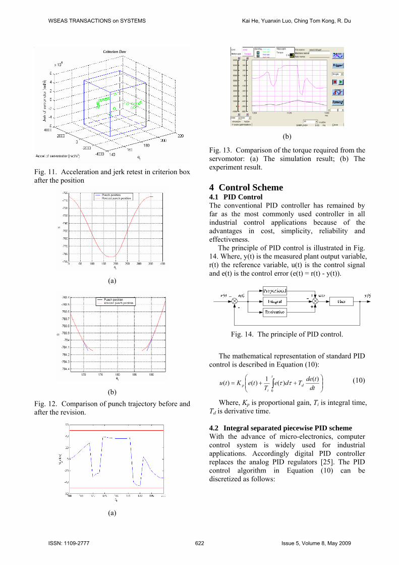
Fig. 11. Acceleration and jerk retest in criterion box after the position
(a)
(b)
Fig. 12. Comparison of punch trajectory before and after the revision.
(a)
(b)
Fig. 13. Comparison of the torque required from the servomotor: (a) The simulation result; (b) The experiment result. 4 Control Scheme 4.1 PID Control The conventional PID controller has remained by far as the most commonly used controller in all industrial control applications because of the advantages in cost, simplicity, reliability and effectiveness.
The principle of PID control is illustrated in Fig. 14. Where, y(t) is the measured plant output variable, r(t) the reference variable, u(t) is the control signal and e(t) is the control error (e(t) = r(t) - y(t)).
Fig. 14. The principle of PID control.
The mathematical representation of standard PID control is described in Equation (10):
⎟⎟⎠
⎞⎜⎜⎝
⎛++= ∫ dt
tdeTdeT
teKtut
di
p)()(1)()(
0
ττ (10)
Where, Kp is proportional gain, Ti is integral time, Td is derivative time. 4.2 Integral separated piecewise PID scheme With the advance of micro-electronics, computer control system is widely used for industrial applications. Accordingly digital PID controller replaces the analog PID regulators [25]. The PID control algorithm in Equation (10) can be discretized as follows:
WSEAS TRANSACTIONS on SYSTEMS Kai He, Yuanxin Luo, Ching Tom Kong, R. Du
ISSN: 1109-2777 622 Issue 5, Volume 8, May 2009

( )
[ ]⎪⎪⎪
⎩
⎪⎪⎪
⎨
⎧
⎪⎪⎪
⎭
⎪⎪⎪
⎬
⎫
−−=
−−≈
=≈
=≈
∫ ∑ ∑= =
Tkeke
TTkekTe
dttde
ieTiTeTdtte
kkTtt k
i
k
i
)1()()1()()(
)()()(
,...2,1,0
0 0 0
(11)
Where, T is sampling interval.
[ ])1()()()()(0
−−++= ∑=
kekeKieKkeKkuk
idip
(12)
Where, Ki=KpT/Ti, Kd=KpTd/T. From Equation (12), it is easy to obtain:
[ ])2()1()()1()1(1
0
−−−++−=− ∑−
=
kekeKieKkeKkuk
idip
(13)
Equation (12) subtracts Equation (13), it follows that
[ ] [ ][ ])1()()()(
)2()1(2)()()1()()(
−Δ−Δ++Δ=
−+−−++−−=Δ
kekeKkeKkeK
kekekeKkeKkekeKku
dip
dip (14)
Where, )1()()( −−=Δ kekeke . Equation (12) is the discretized form of the
increment PID algorithm. This algorithm has good efficiency because there is no process of adding calculation. It can work well in most cases, but the problem is that it may cause integral windup. If the error is non-zero, the integral term will keep integrating and the output will continue to increase or decrease. This normally is not a problem and is a normal feature of the loop. But if the actuator that realizes the control action has saturated range limits, and the saturations are neglected, the integrator may suffer from windup. This causes system oscillations and leads to instability. The windup is due to the controller states becoming inconsistent with the saturated control signal, and future correction is ignored until the actuator desaturates.
An integral separated PID algorithm is adopted to deal with integral windup. It is an easy and direct way. The method is illustrated as follows: • Set a threshold value ε > 0. • When |e(k)| > ε, PD algorithm is implemented,
which reduces the overshoot, improves the response and avoid the integral windup.
• When |e(k)| < = ε, PID algorithm is implemented, which ensures the control accuracy.
It is obvious that how to choose the threshold value is very important, which determines if the algorithm is successful in the application. It is related with the hardware and software architecture of the control system.
This hybrid mechanical press is a highly nonlinear system. The PID parameters auto-tuning is very hard. Actually it is not necessary to realize feedback control in an entire punch stroke. PID control can be only used for guaranteeing the
position accuracy of BDC and its neighbour area which are important for product quality. According to simple and efficiency principle, if the gain fixed PID algorithm satisfies the machine accuracy requirement, it is no need to tune the gain parameters for the punch motion. If the gain fixed PID algorithm cannot satisfy the punch accuracy requirement at or near BDC, a piecewise PID algorithm can be used to fine tune the punch position. It is based on the experiments discussed later. 4.3 Cascade feedback control Cascade control has been by far the main control structure in machine tools because of its many advantages [26, 27]. The controllers of industrial CNC machines are usually based on cascade structure which includes current feedback control as an inner feedback control compensating for the motor and load inertia, velocity feedback control as an outer loop improving the capability of load-disturbance rejection and suppressing velocity variation, and position feedback control as an outer loop guaranteeing perfect steady state precision and dynamic tracking performance, and making the system run steadily and effectively. This structure improves the robustness of the controller with respect to the disturbances and modelling errors.
Develop an able control system is a major challenge for the hybrid press. A cascade control structure is implemented because of the merits mentioned above. The block diagram of the control system for the hybrid mechanical press is illustrated in Fig. 15. The current loop and velocity loop shown in the figure are the built-in control loops of the servomotor. It is known for a mechanical press, the position control is a key part which ensures the punch position accuracy and the repeatability accuracy of the punch at BDC.
Controller
Position feedback
Velocity feedback
Current feedback
Desired punch
trajectory
Inverse kinematics
Trajectory modifying algorithm
Velocity control
Current control PWM Servo
motor
2-DOFMechanism
Constantspeed motor
Punch
Position control
Trigger
1θ
2θ
Differential)(kuΔ
r(k)
+-
+
-
+
-e(k)
y(k)
)(kuc +
+
)(kup
Fig. 15. The block diagram of the control system. The integral separated piecewise PID scheme is
implemented in the position control loop shown in Fig. 15. Given a desired punch trajectory r(k) which has been discretized, the open-loop position control signal uc(k) can be obtained through inverse kinematics. This work can be done in advance and the data is kept in memory for on-line calculation.
WSEAS TRANSACTIONS on SYSTEMS Kai He, Yuanxin Luo, Ching Tom Kong, R. Du
ISSN: 1109-2777 623 Issue 5, Volume 8, May 2009

When the interrupt routine starts, first read the current punch position y(k) from the linear encoder, secondly, y(k) is subtracted by r(k), the obtained error e(k) is passed to the trajectory modifying algorithm, i.e. the integral separated piecewise PID algorithm, next combined with the previous two errors, the calculated compensation is added to uc(k), the sum up(k) is sent out to the servomotor amplifier in the interrupt routine for completing the position control. The flowchart of the integral separated piecewise PID algorithm is shown in Fig. 16.
This cascade control scheme solves the difficulties met in the motion control of the hybrid mechanical press. One is the speed fluctuation of the flywheel which affects the control accuracy. A ten-thousand-pulse optical rotation encoder is installed on the crank shaft to measure the angular position of the crank, which is proportional to the angular position of the CSM. The encoder pulse signal is used as hardware interrupt source to trigger the interrupt routine to execute the position control of the punch. The encoder pulse signal reflects the actual motion of the CSM, which contains the information of the speed fluctuation of the flywheel. The encoder pulse triggering interrupt routine realizes the real-time synchronization tracking control of the servomotor in spite of the speed fluctuation of the flywheel.
start
Read given r(k), uc(k)and measured y(k)
e(k) = r(k) - y(k)
|e(k)| > ε
[ ])1()(
)()()(
−Δ−Δ
++Δ=Δ
kekeK
keKkekku
d
ip
[ ])1()()()(
−Δ−Δ
+Δ=Δ
kekeKkekku
d
p
Read segment flag tochoose PID gains
Initial e(0)=e(1)=0
Output )()()( kukuku cp Δ+=
Crank shaft encoderinterrupt
Other tasksY N
Y N
PDcontrol
PIDcontrol
Fig. 16. The flowchart of the integral separated piecewise PID algorithm. 4.4 Simulation and Experiment Results
The typical punch trajectory of sheet forging is taken as example shown in Fig. 17. At the BDC the punch keeps still for a while when the crank rotates about 20 degrees. This will ensure uniform metal deformation. The unit of x-coordinate is the encoder pulses installed on the crank shaft. Ten thousand pulses are produced when the crank rotates one circle. The starting point is the index signal of the encoder. The unit of y-coordinate is the pulses of the linear encoder installed along the punch guide rail. The resolution of the linear encoder is 0.02 mm. The zero value point on y-coordinate stands for the index signal of the linear encoder which can be set as the zero point of y-coordinate. The figure shows the punch trajectory within one cycle.
Fig. 17. The simulation of punch trajectory for sheet forging.
Open-loop control, P and PD control are implemented for the sheet forging operation. The study focuses on the BDC and its neighboring area. The control starts when the punch is close to the BDC. Fig. 18 gives the comparison of the experiment results around the BDC. It is seen that open-loop control, P control (Kp = 3), PD control (Kp = 3, Kd = 1) do not achieve the desired performance. At the rear part of dwelling segment, the punch has left the BDC. In practice, increasing the proportional gain will have a small effect but cannot solve the problem because of the nonlinear relationship between the punch position and the servomotor input.
Then a piecewise PID algorithm is implemented in the experiment. Set Kp = 2, Ki = 1, Kd= 0.5, when encoder pulse 6300 arrives, change the PID gains to Kp = 3, Ki = 0.5, Kd = 0.5. The experiment result is shown in Fig. 19. The punch position has some fluctuation at the BDC. It is clear the fluctuation of the punch position is ± (one linear encoder pulse). A large number of experiments and continuous running of the press confirms this control algorithm
WSEAS TRANSACTIONS on SYSTEMS Kai He, Yuanxin Luo, Ching Tom Kong, R. Du
ISSN: 1109-2777 624 Issue 5, Volume 8, May 2009

guarantees the repeatability accuracy of the press. Fig. 20 shows the actual torque (upper curve) and speed (lower curve) required from the servomotor. The results are from Mitsubishi servomotor monitoring software. It is clear the speed required from the servomotor is small, which is not more than 1000 r/m when the rotation speed of the crank is 20 rpm. The torque has some fluctuations when the speed of the servomotor has some changes. At one moment it almost reaches the 300% of the rated torque of the servomotor. According to the trajectory planning and optimization discussed above, the servomotor is able to realize the punch trajectory for sheet forging operation in this example.
Fig. 18. Experiment results of open-loop, P and PD control for sheet forging.
Fig. 19. Experiment results of piecewise PID control for sheet forging.
Fig. 20. The torque and speed required from the servomotor for sheet forging. 5 Conclusions In this paper, a hybrid mechanical press based on a 2-DOF parallel mechanism is introduced. It is driven by a CSM with a flywheel and a servomotor. A new method to plan the trajectory of the punch with multi-constraints is presented. It is done based on the combination of the inverse kinematics and a cubic spline interpolation arithmetic. Whether a planned trajectory can be realized can be validated using a cubic box, which is formed by the maximum acceleration and the maximum jerk of the servomotor as well as two boundaries of the crank near the BDC. When a point on the trajectory is located inside the box, the trajectory can be realized. Otherwise, it will not be. For those unrealizable points, we can adjust slider at these points and their neighbouring points to make the points realizable.
A closed-loop controller is developed. Two control schemes are implemented. First, the pulse signal of the encoder of the crank is used as the trigger to complete the synchronization tracking control of the servomotor. This solves the problem caused by the speed fluctuation of the flywheel. Second, an improved PID algorithm, called the integral separated piecewise PID scheme, is used to fine tune the control of the servomotor. This algorithm is able to limit the effect of the integral component in the PID to void integral windup. Moreover, it could use different PID parameters to adapt to different segments within one punch motion cycle. Hence, the error of the punch motion, either resulting from the machine assembly or from the machine dynamics, can be compensated. The experiments show the control scheme has a good performance.
WSEAS TRANSACTIONS on SYSTEMS Kai He, Yuanxin Luo, Ching Tom Kong, R. Du
ISSN: 1109-2777 625 Issue 5, Volume 8, May 2009

Acknowledgements The authors wish to thank Guangdong Metal Forming Machine Works Co. Ltd., China, who helped us build the prototype. References: [1] L. C. Tokuz and J. R. Jones, “Programmable
Modulation of Motion Using Hybrid Machines’’, Proceedings of IMECHE, C414/071, 1991, pp. 85-91.
[2] L. C. Tokuz, “Hybrid Machine Modeling and Control”, Ph.D. Dissertation, Liverpool Polytechnic University, 1992.
[3] J. D. Greenough, W. K. Bradshaw and M. J. Gilmartin, “Design of Hybrid Machine,” Proceedings of the 9th World Congress on the theory of Machines and Mechanisms, 1995, pp. 2501-2505.
[4] J. Van de Straete Herman and De Schutter Joris, “Hybrid Cam Mechanisms”, IEEE/ASME Trans. Mechatronics., Vol. 1, No. 4, pp. 284-289, 1996.
[5] R. Du and W. Z. Guo, “The Design of a New Metal Forming Press with Controllable Mechanism,” Trans. ASME J. Mech. Des., Vol. 125, No. 3, pp. 582-592, 2003.
[6] K. Yeung, W. Z. Guo and R. Du, “The Prototype of a New Metal Forming Press Using Controllable Mechanism,” CIRP 2nd Int. Conf. on Reconfigurable Manuf., Ann Arbor, MI, USA, 2003.
[7] W. Z. Guo, K. He, K. Yeung and R. Du, “A New Type of Controllable Mechanical Press: Motion Control and Experiment Validation", Trans. ASME J. Manuf. Sci. Eng., Vol. 127, Issue 4, pp. 731-742, 2005.
[8] H. Li, “Fundamental Study on the Hybrid-driven Programmable Mechanical Press”, Ph.D. Dissertation, Tianjing University, 2003 (in Chinese).
[9] H. Li, “Dynamic Analysis and Simulation of Hybrid-Driven Mechanical Press for Precision Drawing”, Journal of Computer-Aided Design and Computer Graphics, Vol. 16, No. 5, pp. 666-670, 2004 (in Chinese).
[10] H. Li, C. Zhang, Y. Song and C. Meng, “Dynamic Formulation and Simulation of the Programmable Press”, Chinese J. of Mech. Eng., Vol. 41, No. 3, pp. 180-184, 2005.
[11] C. F. Meng, C. Zhang, Y. H. Lu, et al., “Optimal Design and Control of a Novel Press with an Extra Motor”, Mechanism and Machine Theory, Vol. 39, pp. 811-818, 2004.
[12] P. R. Ouyang, “Hybrid Intelligent Machine Systems: Design, Modeling and Control”, Ph.D. Dissertation, University of Saskatchewan, 2005.
[13] A. Gasparetto and V. Zanotto, “A New Method for Smooth Trajectory Planning of Robot Manipulators”, Mechanism and Machine Theory, Vol. 42, pp. 455-471, 2007.
[14] H. Asada and Y. T. Kamal, Direct-drive Robots: Theory and Practice, Cambridge, Mass: MIT Press, 1987.
[15] J. Angeles, Fundamentals of Robotic Mechanical Systems: Theory, Methods, and Algorithms, New York: Springer, 1997.
[16] S. B. Niku, Introduction to Robotics – Analysis, Systems, Applications, New Jersey: Prentice Hall, 2001.
[17] K. J. Kyriakopoulos and G. N. Saridis, “Minimum Jerk Path Generation”, Proc. of IEEE Int. Conf. on Robot. Autom., Philadelphia, PA, 1988, pp. 364-369.
[18] A. Piazzi and A. Visioli, “Global Minimum-time Trajectory Planning of Mechanical Manipulators Using Interval Analysis”, International Journal of Control, Vol. 71, No. 4, pp. 631-652, 1998.
[19] J. T. Betts, “Survey of Numerical Methods for Trajectory Optimization”, J. Guidance, Control, and Dynamics, Vol. 21, No. 2, pp. 193-207, 1998.
[20] A. Visioli, “Global Minimum-jerk Trajectory Planning of Robot Manipulators”, IEEE Trans. Industrial Electronics, Vol. 47, Issue 1, pp. 140-149, 2000.
[21] Z. L. Jin, K. He and R. Du, “On the Design of a Novel Controllable Mechanical Metal Forming Press Based on 2-D Planar Mechanism”, ASME 2005 International Design Engineering Technical Conferences & Computers and Information in Engineering Conference, Long Beach, California, USA, September 24-28.
[22] J. J. Craig, Introduction to Robotics: Mechanics and Control (2nd edition), Reading, MA: Addison-Wesley, 1989.
[23] C. W. Xu and S. W. Sun, Introduction of Computing Method, 2nd Edition, Higher Education Press, Beijing (in Chinese), 2002.
[24] K. He, W. M. Li and R. Du, “Dynamic Modelling with Kineto-static Method and Experiment Validation of a Novel Controllable Mechanical Metal Forming Press”, Int. J. Manufacturing Research, Vol. 1, No. 3, pp. 354-378, 2006.
[25] L. Samet, N. Masmoudi, M. W. Kharrat and L. Kamoun, “A Digital PID Controller for Real Time and Multi Loop Control: a Comparative Study”, IEEE Int. Conf. on Electronics, Circuits and Systems, Vol. 1, pp. 291-296, 1998.
WSEAS TRANSACTIONS on SYSTEMS Kai He, Yuanxin Luo, Ching Tom Kong, R. Du
ISSN: 1109-2777 626 Issue 5, Volume 8, May 2009

[26] G. Brandenburg and W. Papiernik, “Feedforward and Feedback Strategies Applying the Principle of Input Balancing for Minimal Tracking Errors in CNC Machine Tools”, 4th Int. Workshop on Advanced Motion Control, Vol. 2, pp. 612-618, 1996.
[27] X. Huang and L. Shi, “Simulation on a Fuzzy-PID Position Controller of the CNC Servo System”, Proc. of the Sixth Int. Conf. on Intelligent Systems Design and Application, Vol. 1, pp. 305-309, October 2006.
WSEAS TRANSACTIONS on SYSTEMS Kai He, Yuanxin Luo, Ching Tom Kong, R. Du
ISSN: 1109-2777 627 Issue 5, Volume 8, May 2009