transformer & oltc
DESCRIPTION
TRANSCRIPT
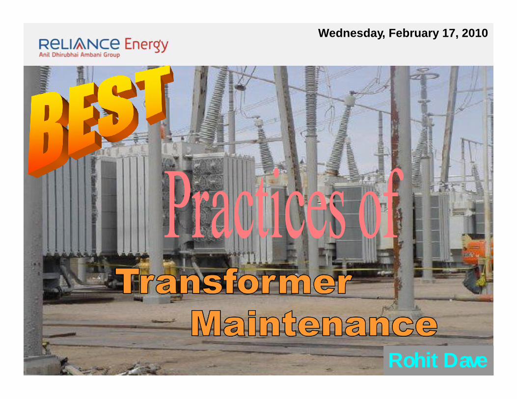
Wednesday, February 17, 2010
Rohit Dave
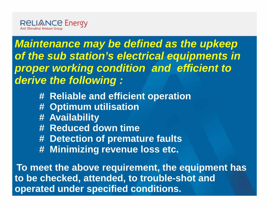
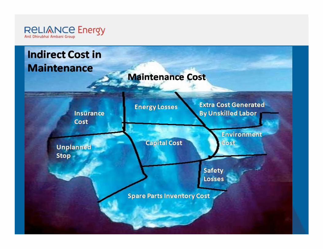
Maintenance may be defined as the upkeep of the sub station’s electrical equipments in proper working condition and efficient to derive the following :
# Reliable and efficient operation # Optimum utilisation # Availability # Reduced down time# Detection of premature faults # Minimizing revenue loss etc.
To meet the above requirement, the equipment has to be checked, attended, to trouble-shot and operated under specified conditions.
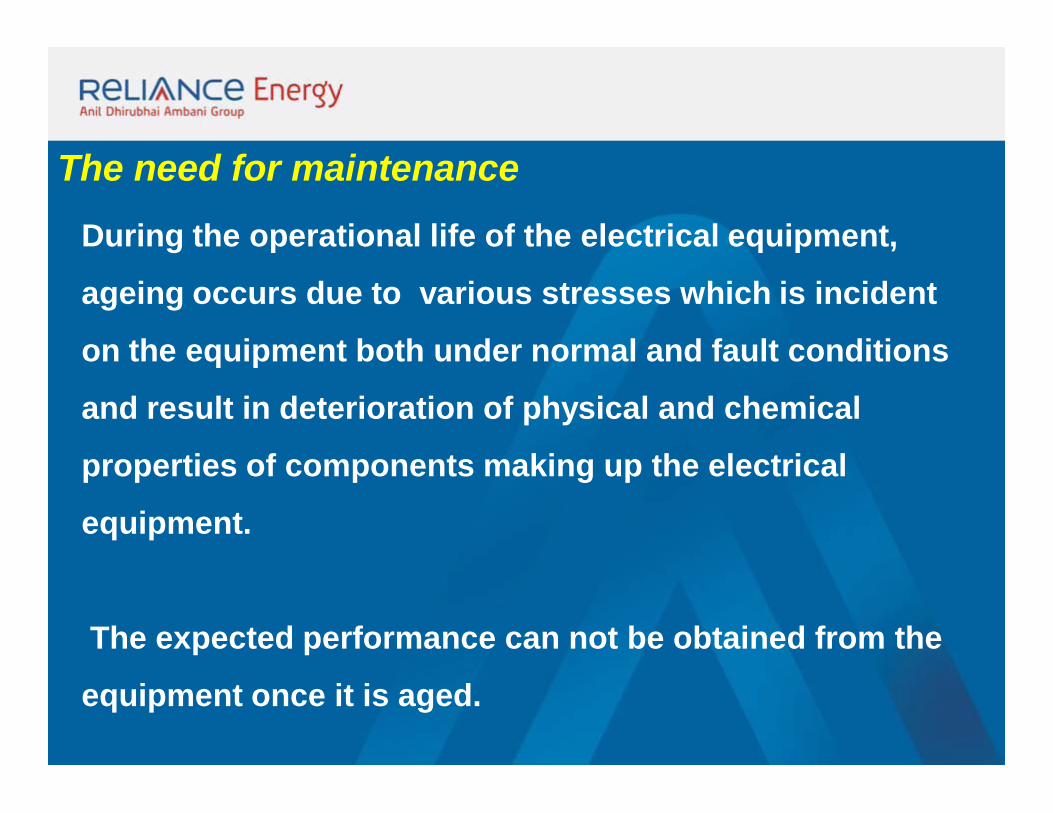
The need for maintenance
During the operational life of the electrical equipment,
ageing occurs due to various stresses which is incident
on the equipment both under normal and fault conditions
and result in deterioration of physical and chemical
properties of components making up the electrical
equipment.
The expected performance can not be obtained from the
equipment once it is aged.
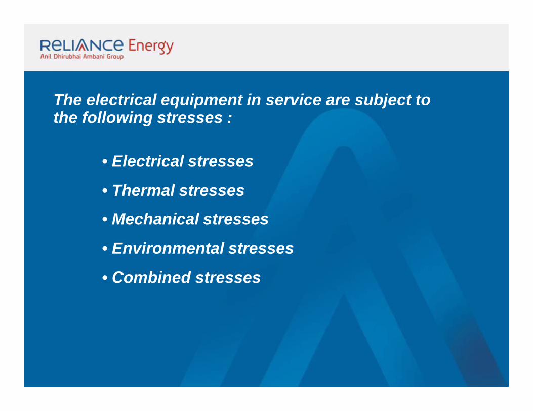
The electrical equipment in service are subject to the following stresses :
• Electrical stresses
• Thermal stresses
• Mechanical stresses
• Environmental stresses
• Combined stresses
Electrical Stress: The Insulation of electrical equipment experience the
following voltages :
• Continuous normal power frequency rated voltage
• Temporary power frequency over voltages due to voltage
regulation, Ferranti effect, and long duration power
frequency over voltages. • Lightning Impulse Voltage Waves (Surges)• Switching Impulse Waves (Surges)
Thermal Stress
Elevated temperatures may be reached during
operation due to dielectric losses, increased I2R loss
or by heat absorption from surroundings.
Temperature may increase abnormally due to
sustained short circuit current.
The cooling system failure in power transformers
also stress the windings thermally.
Mechanical Stress
There may be permanent mechanical stress due
to improper installation
Circuit breakers may experience vibration stress
during normal closing/opening and during making /
breaking under fault
The bus bar vibration in rigid bus bar stresses the
bus bar support mechanically
Environmental stress
Environmental factors include pollution, Radiation,
Humidity, dust particles, moisture etc,.
Proximity to chemical industry, sea coast and
intentional damage caused by humans contribute to
ageing and deterioration
Combined stress
In most of the electrical equipment, normally
some of the stress factors as above will be present
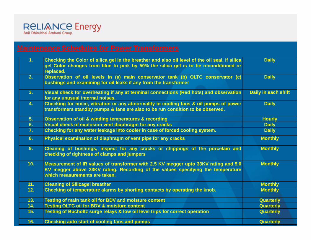
Maintenance Schedules for Power Transformers1. Checking the Color of silica gel in the breather and also oil level of the oil seal. If silica
gel Color changes from blue to pink by 50% the silica gel is to be reconditioned orreplaced.
Daily
2. Observation of oil levels in (a) main conservator tank (b) OLTC conservator (c)bushings and examining for oil leaks if any from the transformer
Daily
3. Visual check for overheating if any at terminal connections (Red hots) and observationfor any unusual internal noises.
Daily in each shift
4. Checking for noice, vibration or any abnormality in cooling fans & oil pumps of powertransformers standby pumps & fans are also to be run condition to be observed.
Daily
5. Observation of oil & winding temperatures & recording Hourly6. Visual check of explosion vent diaphragm for any cracks Daily7. Checking for any water leakage into cooler in case of forced cooling system. Daily8. Physical examination of diaphragm of vent pipe for any cracks Monthly
9. Cleaning of bushings, inspect for any cracks or chippings of the porcelain andchecking of tightness of clamps and jumpers
Monthly
10. Measurement of IR values of transformer with 2.5 KV megger upto 33KV rating and 5.0KV megger above 33KV rating. Recording of the values specifying the temperaturewhich measurements are taken.
Monthly
11. Cleaning of Silicagel breather Monthly12. Checking of temperature alarms by shorting contacts by operating the knob. Monthly
13. Testing of main tank oil for BDV and moisture content Quarterly14. Testing OLTC oil for BDV & moisture content Quarterly15. Testing of Bucholtz surge relays & low oil level trips for correct operation Quarterly
16. Checking auto start of cooling fans and pumps Quarterly
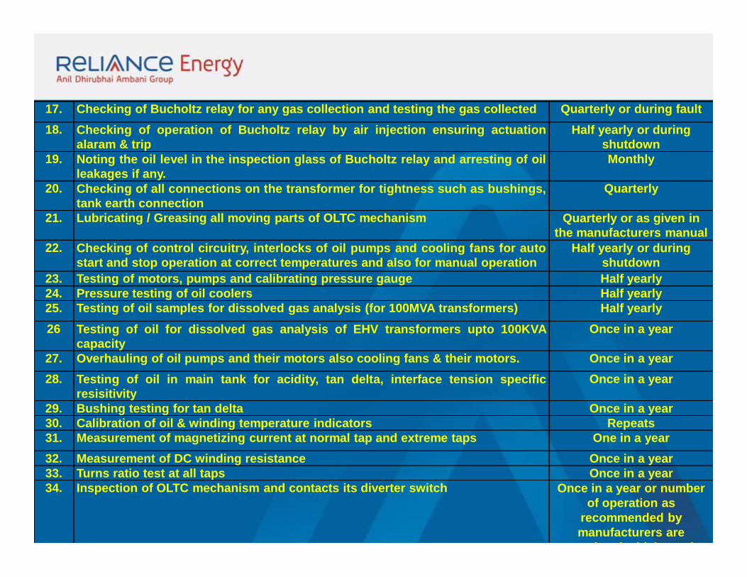
17. Checking of Bucholtz relay for any gas collection and testing the gas collected Quarterly or during fault18. Checking of operation of Bucholtz relay by air injection ensuring actuation
alaram & tripHalf yearly or during
shutdown19. Noting the oil level in the inspection glass of Bucholtz relay and arresting of oil
leakages if any.Monthly
20. Checking of all connections on the transformer for tightness such as bushings,tank earth connection
Quarterly
21. Lubricating / Greasing all moving parts of OLTC mechanism Quarterly or as given in the manufacturers manual
22. Checking of control circuitry, interlocks of oil pumps and cooling fans for autostart and stop operation at correct temperatures and also for manual operation
Half yearly or during shutdown
23. Testing of motors, pumps and calibrating pressure gauge Half yearly24. Pressure testing of oil coolers Half yearly25. Testing of oil samples for dissolved gas analysis (for 100MVA transformers) Half yearly26 Testing of oil for dissolved gas analysis of EHV transformers upto 100KVA
capacityOnce in a year
27. Overhauling of oil pumps and their motors also cooling fans & their motors. Once in a year28. Testing of oil in main tank for acidity, tan delta, interface tension specific
resisitivityOnce in a year
29. Bushing testing for tan delta Once in a year30. Calibration of oil & winding temperature indicators Repeats31. Measurement of magnetizing current at normal tap and extreme taps One in a year32. Measurement of DC winding resistance Once in a year33. Turns ratio test at all taps Once in a year34. Inspection of OLTC mechanism and contacts its diverter switch Once in a year or number
of operation as recommended by manufacturers are
completed whichever is
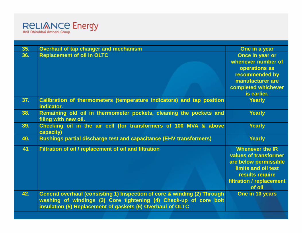
35. Overhaul of tap changer and mechanism One in a year36. Replacement of oil in OLTC Once in year or
whenever number of operations as
recommended by manufacturer are
completed whichever is earlier.
37. Calibration of thermometers (temperature indicators) and tap positionindicator.
Yearly
38. Remaining old oil in thermometer pockets, cleaning the pockets andfiling with new oil.
Yearly
39. Checking oil in the air cell (for transformers of 100 MVA & abovecapacity)
Yearly
40. Bushings partial discharge test and capacitance (EHV transformers) Yearly
41 Filtration of oil / replacement of oil and filtration Whenever the IR values of transformer are below permissible
limits and oil test results require
filtration / replacement of oil
42. General overhaul (consisting 1) Inspection of core & winding (2) Throughwashing of windings (3) Core tightening (4) Check-up of core boltinsulation (5) Replacement of gaskets (6) Overhaul of OLTC
One in 10 years
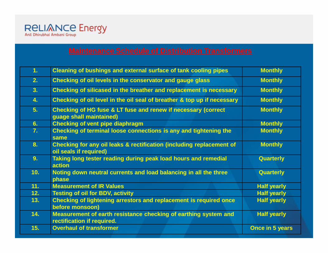
1. Cleaning of bushings and external surface of tank cooling pipes Monthly2. Checking of oil levels in the conservator and gauge glass Monthly3. Checking of silicased in the breather and replacement is necessary Monthly4. Checking of oil level in the oil seal of breather & top up if necessary Monthly5. Checking of HG fuse & LT fuse and renew if necessary (correct
guage shall maintained)Monthly
6. Checking of vent pipe diaphragm Monthly7. Checking of terminal loose connections is any and tightening the
sameMonthly
8. Checking for any oil leaks & rectification (including replacement of oil seals if required)
Monthly
9. Taking long tester reading during peak load hours and remedial action
Quarterly
10. Noting down neutral currents and load balancing in all the three phase
Quarterly
11. Measurement of IR Values Half yearly12. Testing of oil for BDV, activity Half yearly13. Checking of lightening arrestors and replacement is required once
before monsoon)Half yearly
14. Measurement of earth resistance checking of earthing system and rectification if required.
Half yearly
15. Overhaul of transformer Once in 5 years
Maintenance Schedule of Distribution Transformers
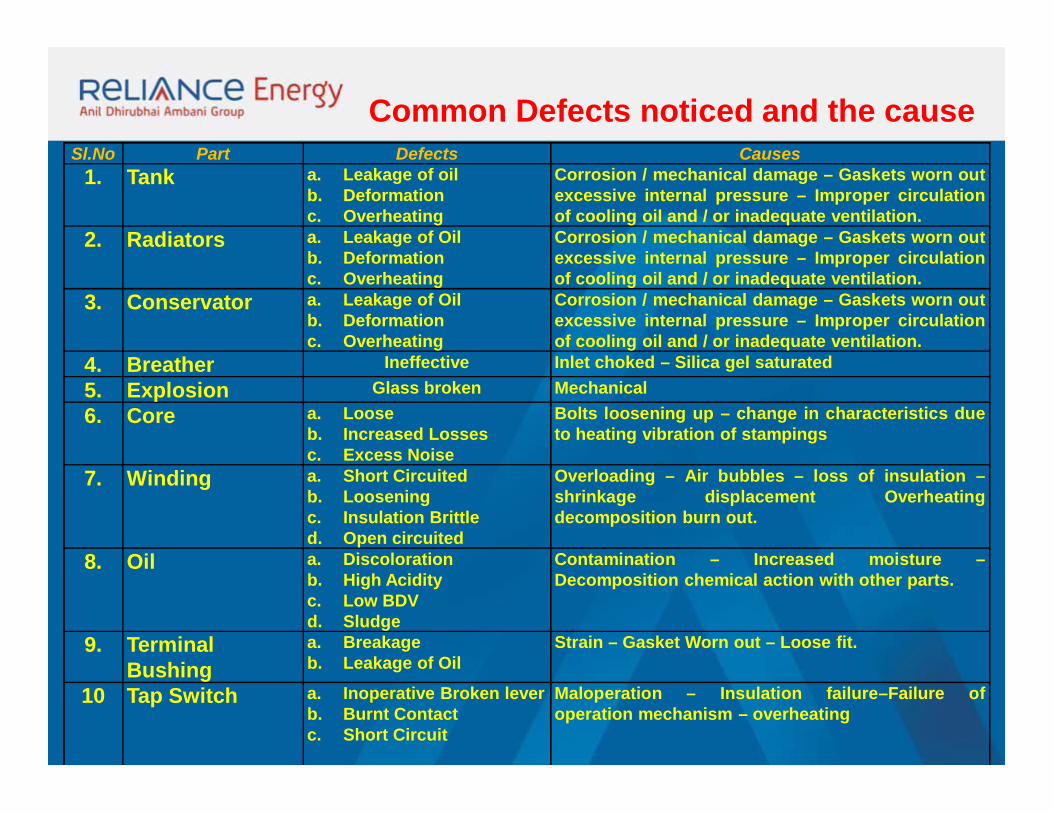
Sl.No Part Defects Causes1. Tank a. Leakage of oil
b. Deformationc. Overheating
Corrosion / mechanical damage – Gaskets worn outexcessive internal pressure – Improper circulationof cooling oil and / or inadequate ventilation.
2. Radiators a. Leakage of Oilb. Deformationc. Overheating
Corrosion / mechanical damage – Gaskets worn outexcessive internal pressure – Improper circulationof cooling oil and / or inadequate ventilation.
3. Conservator a. Leakage of Oilb. Deformationc. Overheating
Corrosion / mechanical damage – Gaskets worn outexcessive internal pressure – Improper circulationof cooling oil and / or inadequate ventilation.
4. Breather Ineffective Inlet choked – Silica gel saturated5. Explosion Glass broken Mechanical6. Core a. Loose
b. Increased Lossesc. Excess Noise
Bolts loosening up – change in characteristics dueto heating vibration of stampings
7. Winding a. Short Circuitedb. Looseningc. Insulation Brittled. Open circuited
Overloading – Air bubbles – loss of insulation –shrinkage displacement Overheatingdecomposition burn out.
8. Oil a. Discolorationb. High Acidityc. Low BDVd. Sludge
Contamination – Increased moisture –Decomposition chemical action with other parts.
9. Terminal Bushing
a. Breakageb. Leakage of Oil
Strain – Gasket Worn out – Loose fit.
10 Tap Switch a. Inoperative Broken leverb. Burnt Contactc. Short Circuit
Maloperation – Insulation failure–Failure ofoperation mechanism – overheating
Common Defects noticed and the cause
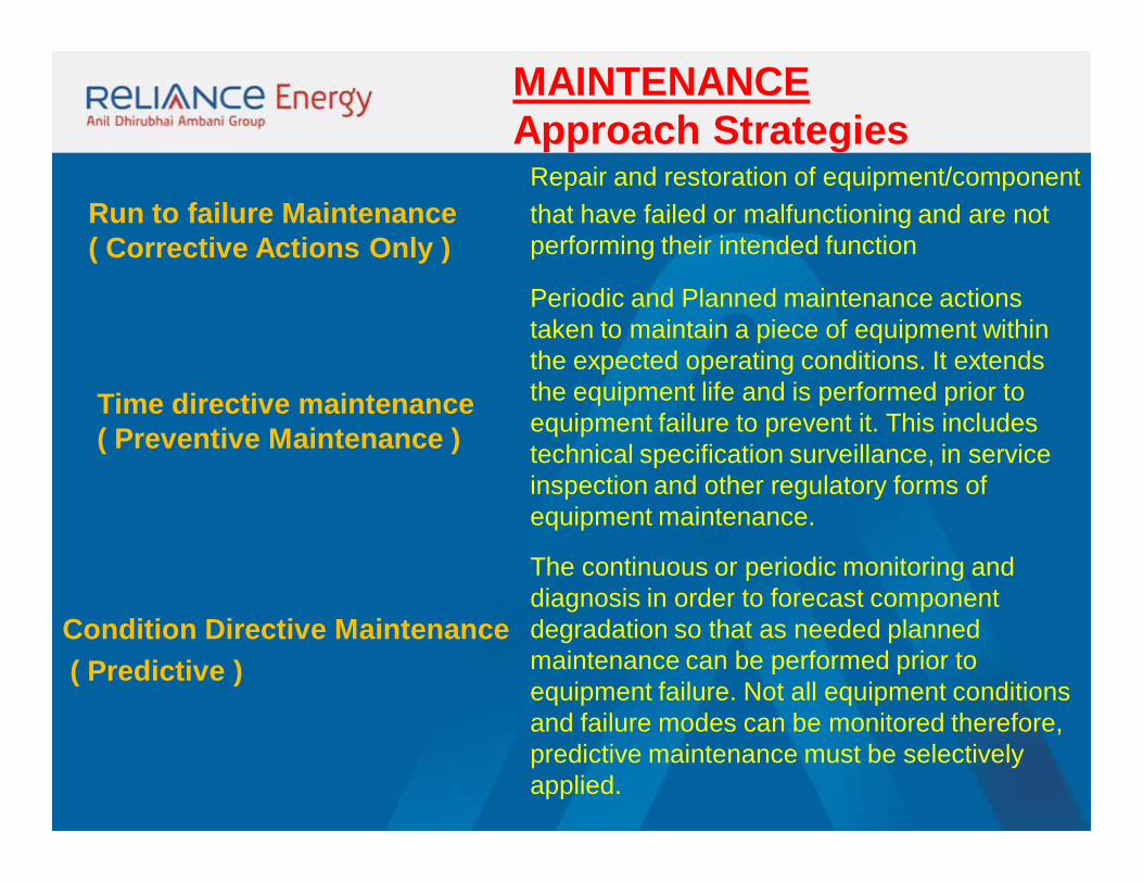
Run to failure Maintenance( Corrective Actions Only )
Time directive maintenance( Preventive Maintenance )
Condition Directive Maintenance ( Predictive )
Repair and restoration of equipment/component that have failed or malfunctioning and are not performing their intended function
Periodic and Planned maintenance actions taken to maintain a piece of equipment within the expected operating conditions. It extends the equipment life and is performed prior to equipment failure to prevent it. This includes technical specification surveillance, in service inspection and other regulatory forms of equipment maintenance.
MAINTENANCEApproach Strategies
The continuous or periodic monitoring and diagnosis in order to forecast component degradation so that as needed planned maintenance can be performed prior to equipment failure. Not all equipment conditions and failure modes can be monitored therefore, predictive maintenance must be selectively applied.
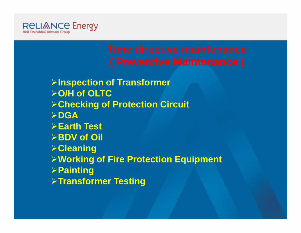
Time directive maintenance( Preventive Maintenance )
Inspection of TransformerO/H of OLTCChecking of Protection CircuitDGAEarth TestBDV of OilCleaningWorking of Fire Protection EquipmentPaintingTransformer Testing
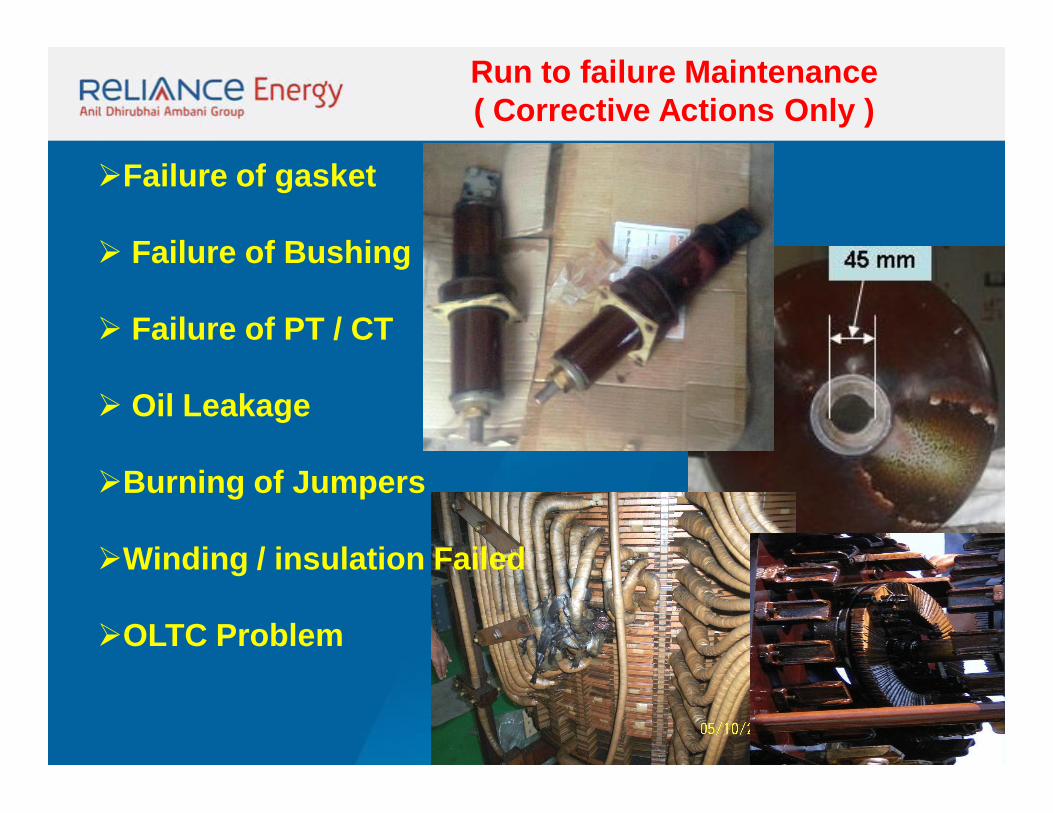
Run to failure Maintenance( Corrective Actions Only )
Failure of gasket
Failure of Bushing
Failure of PT / CT
Oil Leakage
Burning of Jumpers
Winding / insulation Failed
OLTC Problem
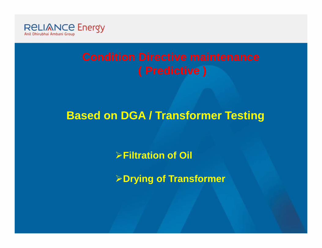
Condition Directive maintenance ( Predictive )
Filtration of Oil
Drying of Transformer
Based on DGA / Transformer Testing
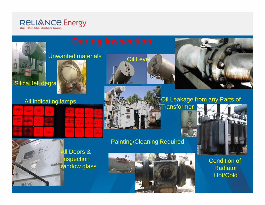
During Inspection
Oil Leakage from any Parts of Transformer
Painting/Cleaning Required
Oil Level
Silica Jell degraded
All indicating lamps
Condition of RadiatorHot/Cold
All Doors &inspectionwindow glass
Unwanted materials
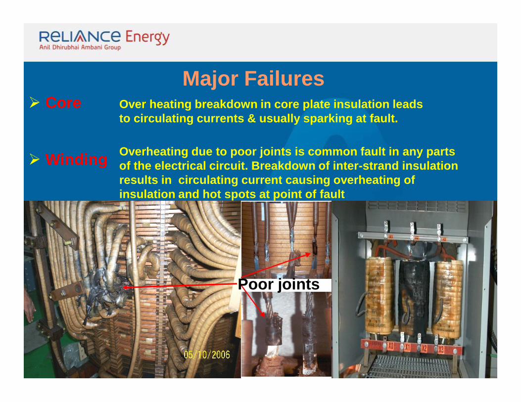
Core
Winding
Over heating breakdown in core plate insulation leads to circulating currents & usually sparking at fault.
Major Failures
Overheating due to poor joints is common fault in any parts of the electrical circuit. Breakdown of inter-strand insulation results in circulating current causing overheating of insulation and hot spots at point of fault
Poor joints
OLTC
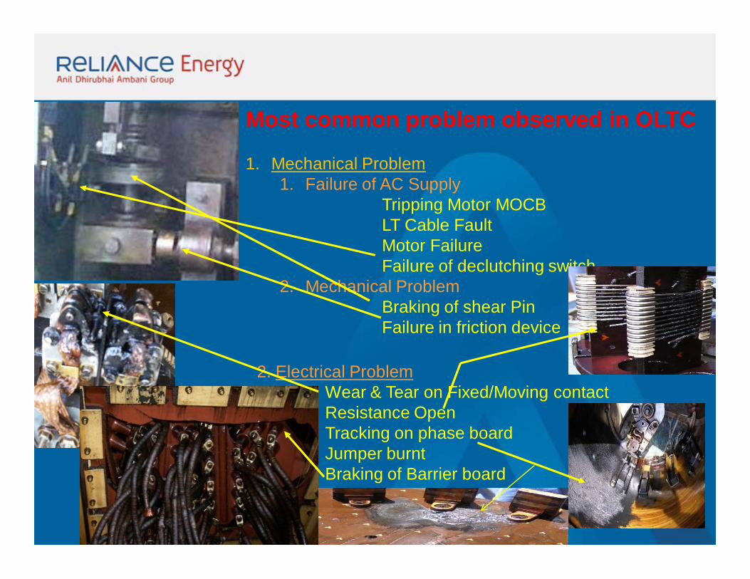
Most common problem observed in OLTC
1. Mechanical Problem1. Failure of AC Supply
Tripping Motor MOCBLT Cable FaultMotor FailureFailure of declutching switch
2. Mechanical ProblemBraking of shear PinFailure in friction device
2. Electrical ProblemWear & Tear on Fixed/Moving contactResistance OpenTracking on phase boardJumper burntBraking of Barrier board
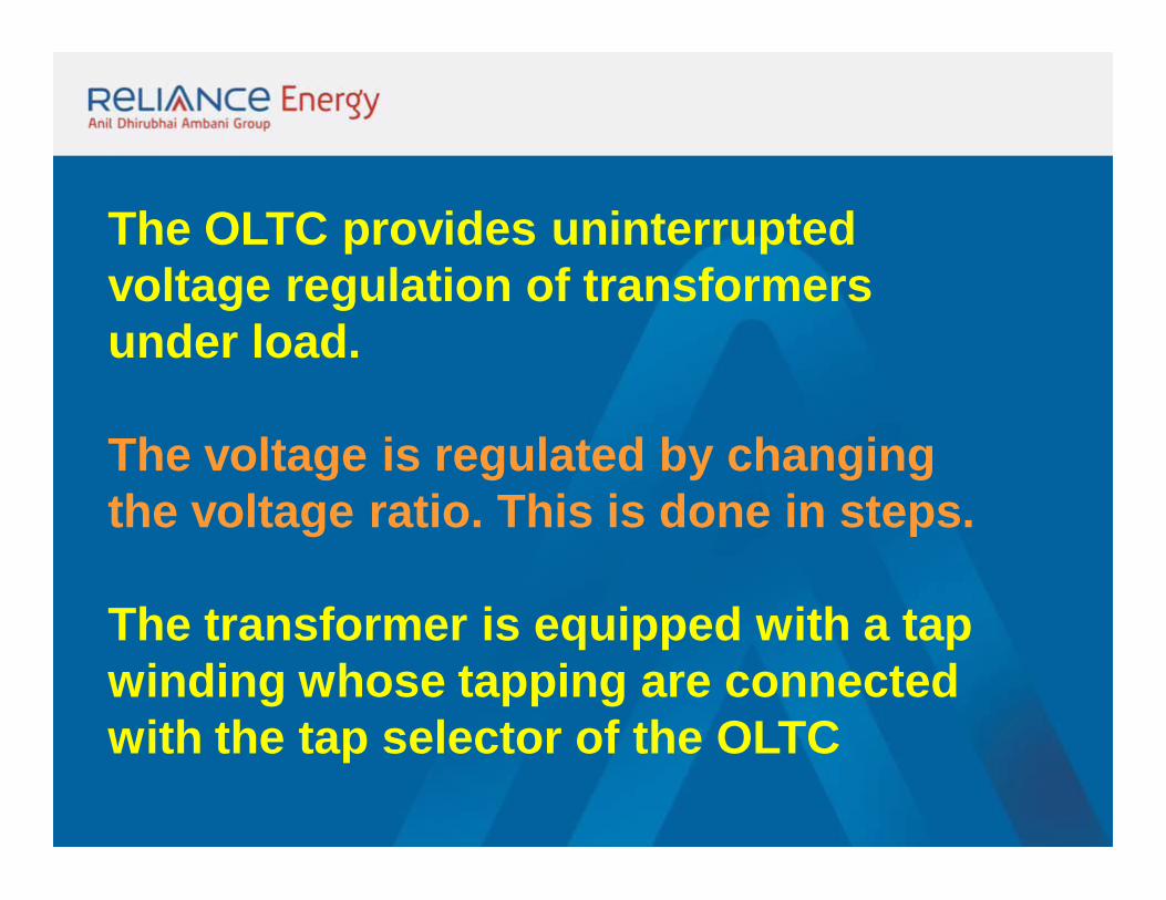
The OLTC provides uninterrupted voltage regulation of transformers under load.
The voltage is regulated by changing the voltage ratio. This is done in steps.
The transformer is equipped with a tap winding whose tapping are connected with the tap selector of the OLTC
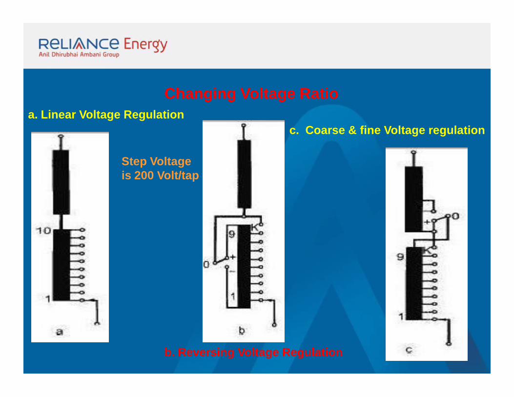
Changing Voltage Ratioa. Linear Voltage Regulation
b. Reversing Voltage Regulation
c. Coarse & fine Voltage regulation
Step Voltageis 200 Volt/tap
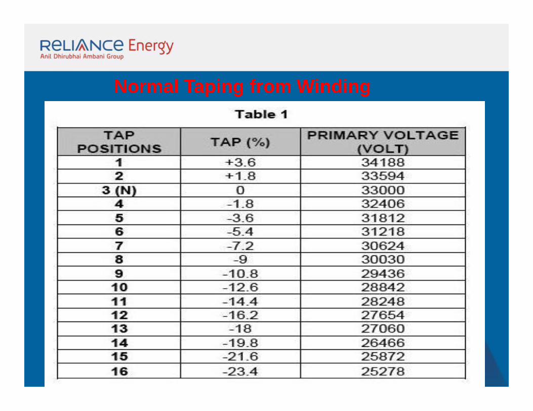
Normal Taping from Winding
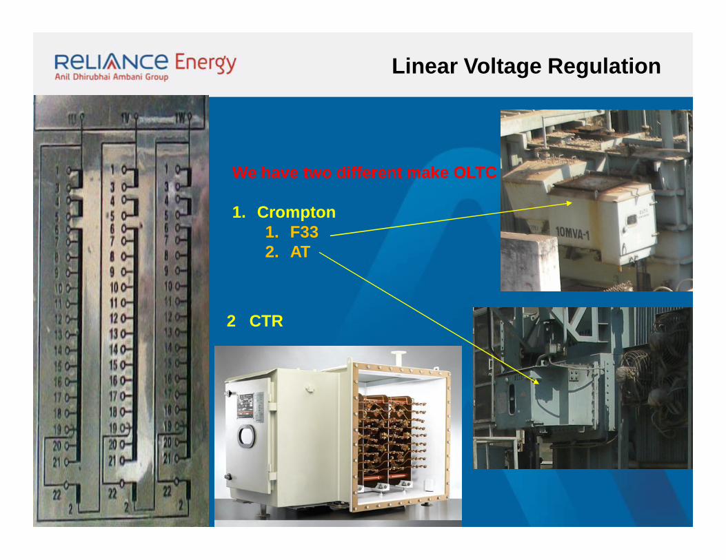
Linear Voltage Regulation
We have two different make OLTC
1. Crompton1. F332. AT
2 CTR
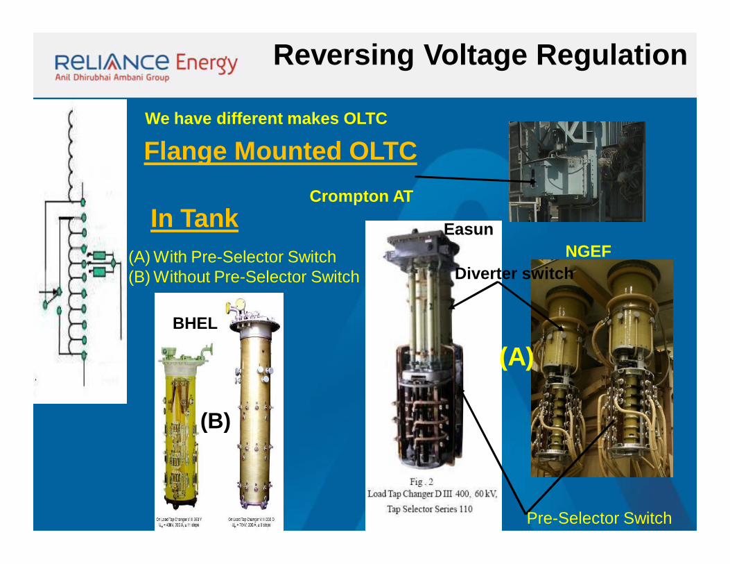
Reversing Voltage Regulation
We have different makes OLTC
Flange Mounted OLTCCrompton AT
NGEF
In Tank(A) With Pre-Selector Switch(B) Without Pre-Selector Switch
Easun
(A)BHEL
(B)
Pre-Selector Switch
Diverter switch
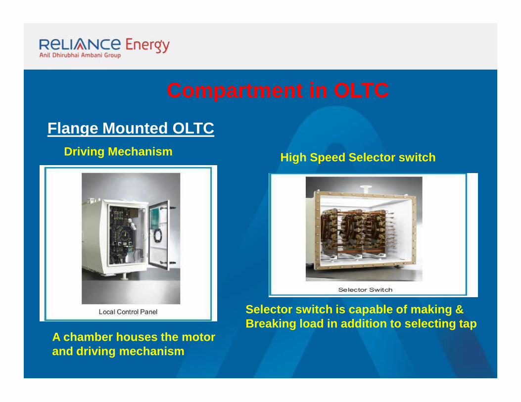
Compartment in OLTCFlange Mounted OLTC
Driving Mechanism High Speed Selector switch
Selector switch is capable of making & Breaking load in addition to selecting tap
A chamber houses the motorand driving mechanism
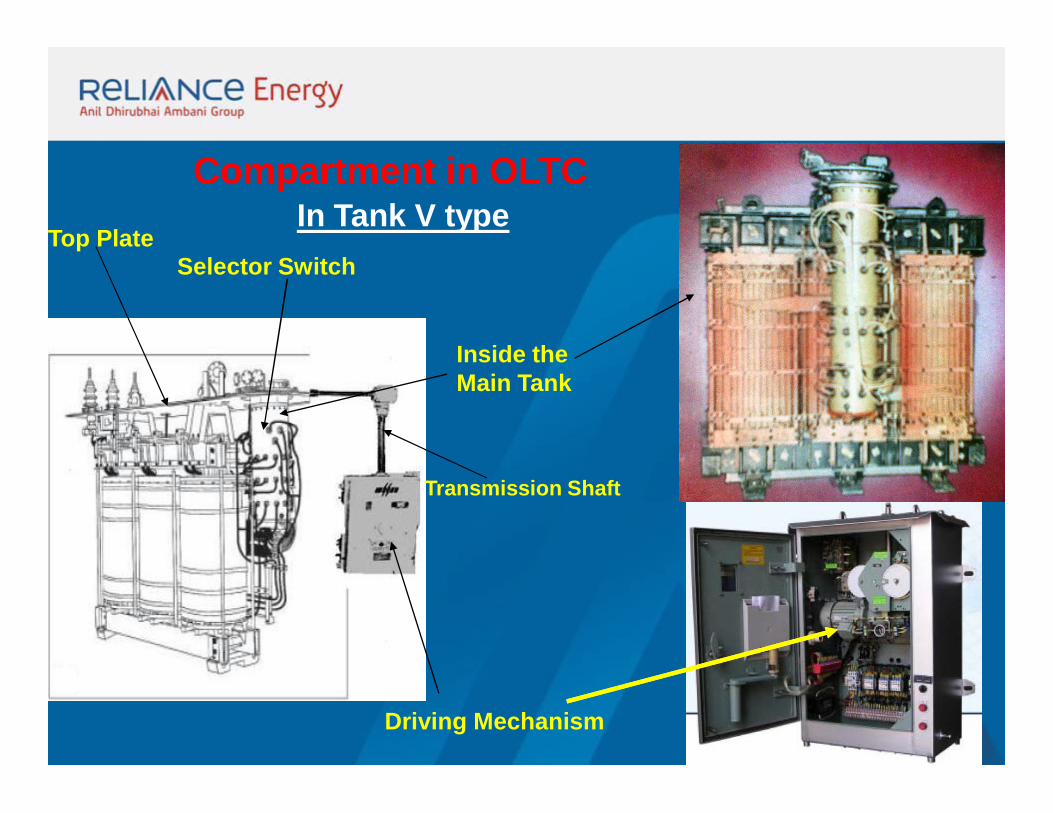
Compartment in OLTCIn Tank V type
Driving Mechanism
Selector Switch
Inside the Main Tank
Transmission Shaft
Top Plate
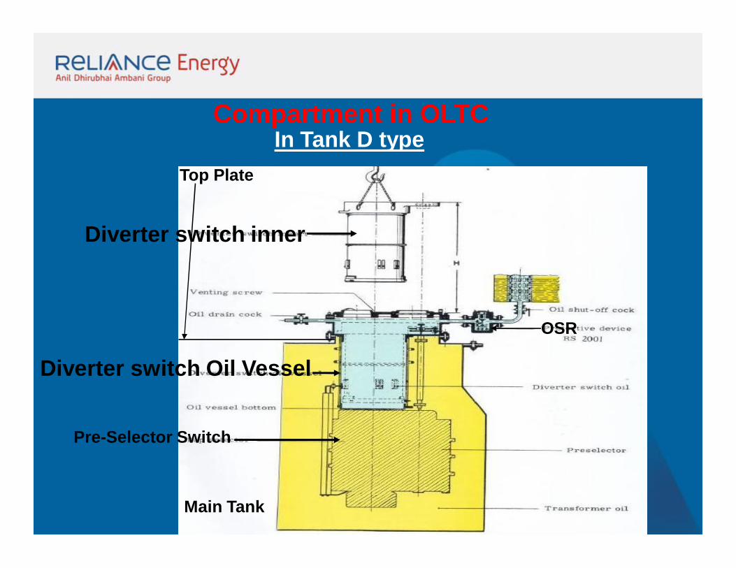
Compartment in OLTCIn Tank D type
Main Tank
Top Plate
Pre-Selector Switch
Diverter switch inner
Diverter switch Oil Vessel
OSR
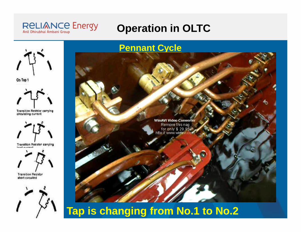
Operation in OLTC
Pennant Cycle
Tap is changing from No.1 to No.2
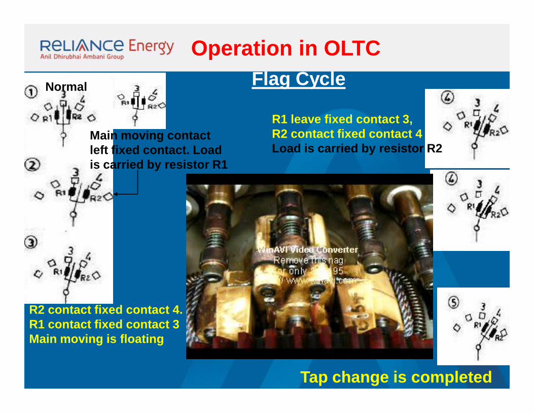
Operation in OLTCFlag Cycle
R2 contact fixed contact 4.R1 contact fixed contact 3Main moving is floating
R1 leave fixed contact 3,R2 contact fixed contact 4Load is carried by resistor R2
Tap change is completed
Normal
Main moving contact left fixed contact. Load is carried by resistor R1
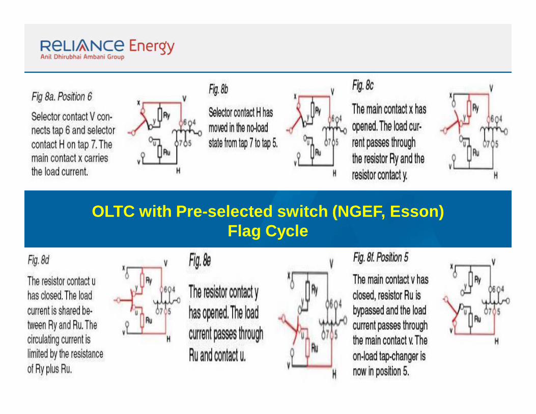
OLTC with Pre-selected switch (NGEF, Esson)Flag Cycle
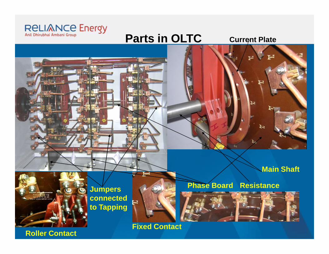
Parts in OLTC
Main Shaft
Phase Board
Fixed Contact
Resistance
Roller Contact
Jumpers connectedto Tapping
Current Plate
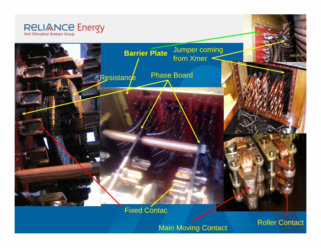
Fixed Contac
Main Moving ContactRoller Contact
Barrier Plate Jumper comingfrom Xmer
Phase BoardResistance
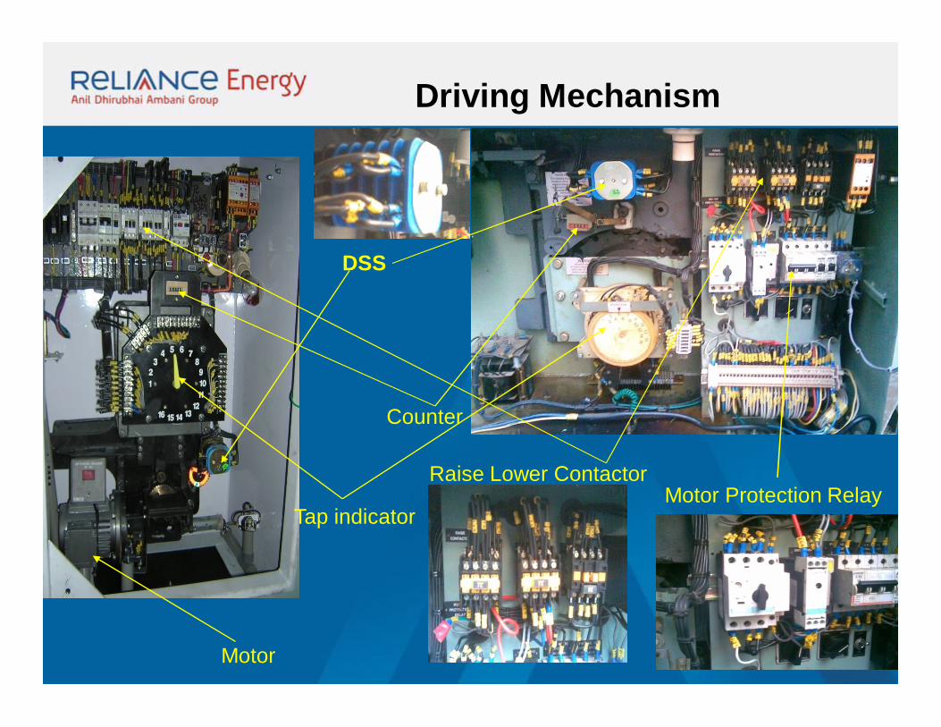
Driving Mechanism
DSS
Tap indicator
Motor
Counter
Raise Lower ContactorMotor Protection Relay
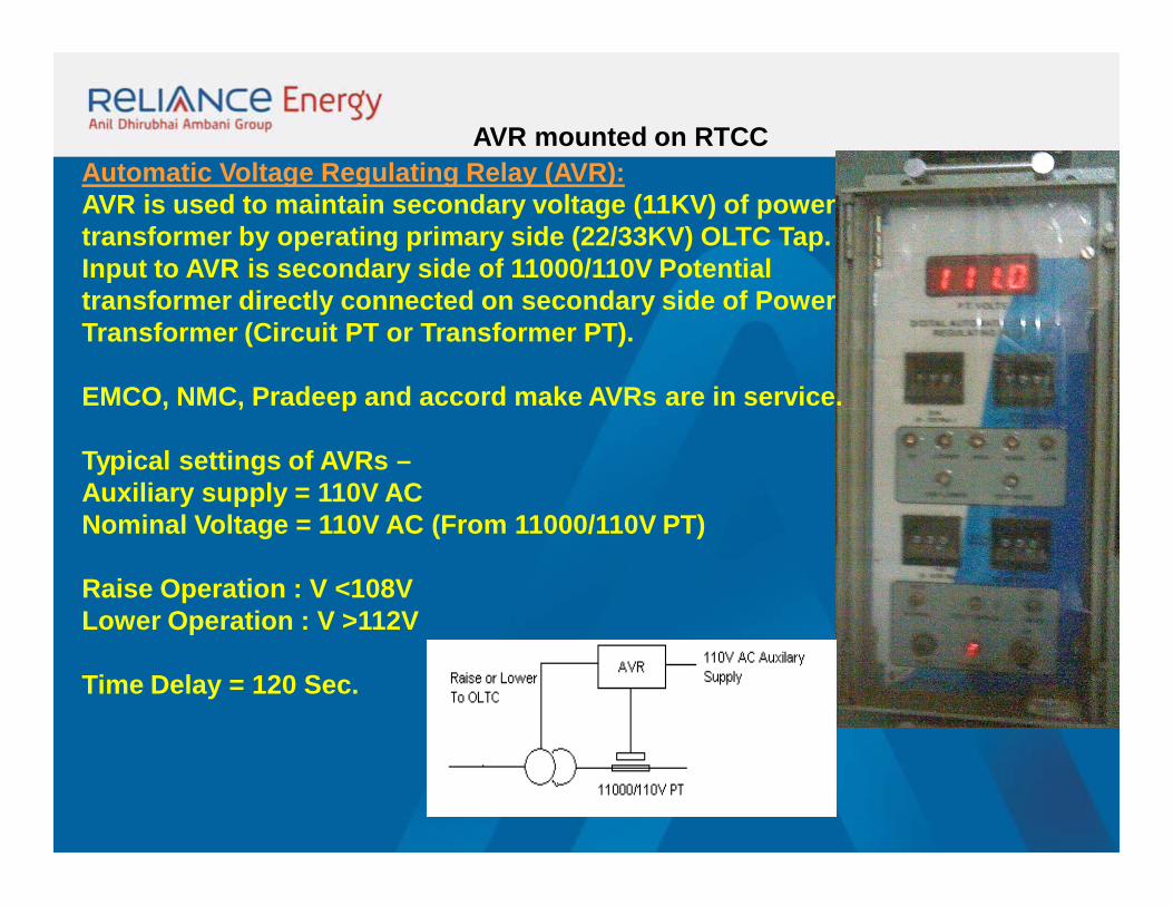
AVR mounted on RTCCAutomatic Voltage Regulating Relay (AVR):AVR is used to maintain secondary voltage (11KV) of power transformer by operating primary side (22/33KV) OLTC Tap. Input to AVR is secondary side of 11000/110V Potential transformer directly connected on secondary side of Power Transformer (Circuit PT or Transformer PT).
EMCO, NMC, Pradeep and accord make AVRs are in service.
Typical settings of AVRs –Auxiliary supply = 110V ACNominal Voltage = 110V AC (From 11000/110V PT)
Raise Operation : V <108VLower Operation : V >112V
Time Delay = 120 Sec.
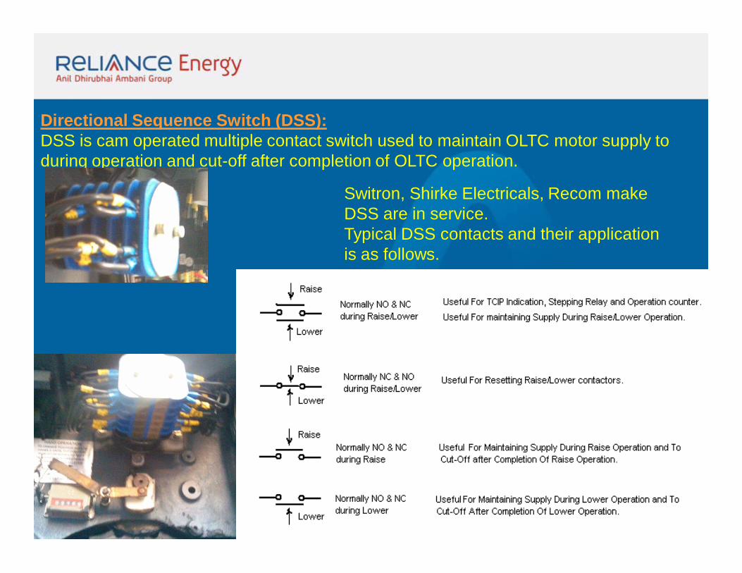
Directional Sequence Switch (DSS):DSS is cam operated multiple contact switch used to maintain OLTC motor supply to during operation and cut-off after completion of OLTC operation.
Switron, Shirke Electricals, Recom make DSS are in service.Typical DSS contacts and their application is as follows.
OLTC Timer Scheme – Timer scheme will operate if motor supply is continuous for more
than set time (Set time=2*time for one operation) and avoids high/lower voltages during DSS and
contactor mal-operation .
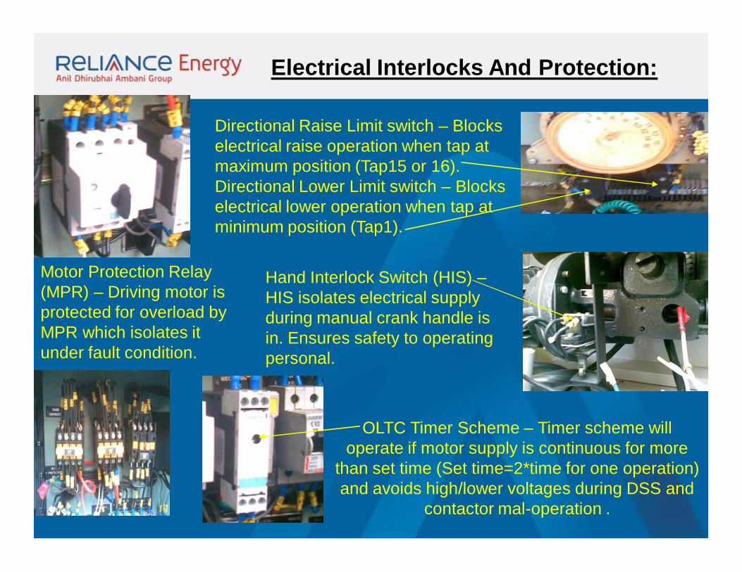
Motor Protection Relay (MPR) – Driving motor is protected for overload by MPR which isolates it under fault condition.
Directional Raise Limit switch – Blocks electrical raise operation when tap at maximum position (Tap15 or 16).Directional Lower Limit switch – Blocks electrical lower operation when tap at minimum position (Tap1).
Electrical Interlocks And Protection:
Hand Interlock Switch (HIS) –HIS isolates electrical supply during manual crank handle is in. Ensures safety to operating personal.
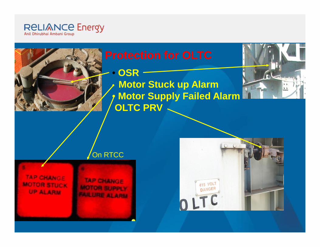
Protection for OLTC• OSR• Motor Stuck up Alarm• Motor Supply Failed AlarmOLTC PRV
On RTCC
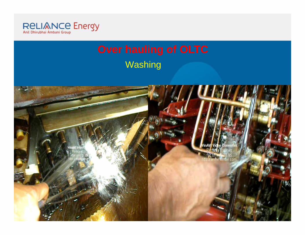
Over hauling of OLTCWashing

Over-hauling of OLTCCleaning
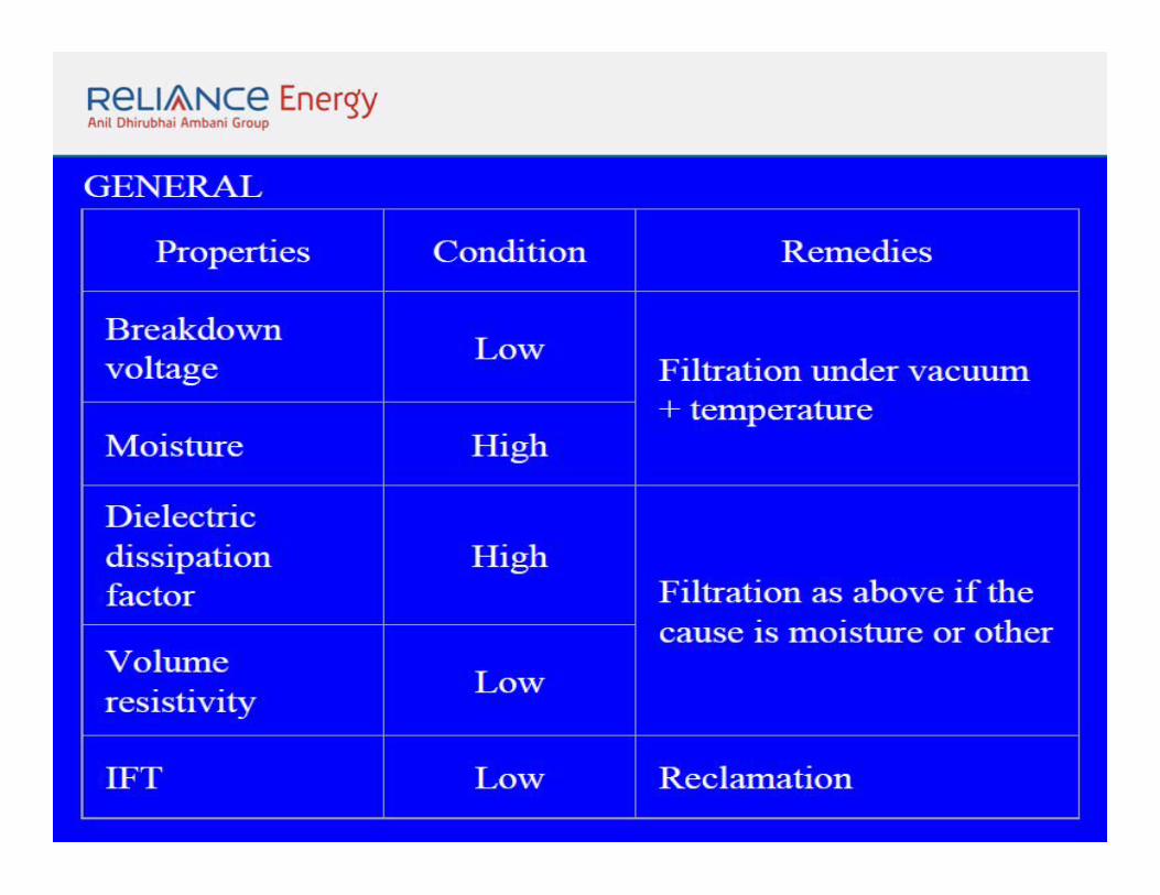
CONDITION MONITORING OF TRANSFORMER OIL
Parameters for condition monitoring of oil service
Two ways are available to an operating engineer
1.To make periodic oil tests to establish trends and classify
them.
2.To conduct dissolved gas analysis to assess the internal
condition of transformers
PARAMETERS TO BE CHECKED ARE:1. FLASH POINT
2.DIELECTRIC DISSIPATION FACTOR
3.SPECIFIC RESISTANCE
4.NEUTRALISATION.
5.MOISTURE CONTENT
6.SLUDGE %
7.BREAK DOWN VOLTAGE
8.D.G.A.
PHYSICAL CONTAMINATION1.Dust, fiber, metallic, particles, other solid impurities.2.Dissolution of varnish.3.Free and dissolved water.
CHEMICAL DETERIORATIONOxidation resulting in acids sludge and polar impurities.
CONTAMINATION OF GASESa) Dissolved air from atm. Nitrogen, co2b) Generated in oil, methane, ethane, acetylene,
ethylene etc. Before the oil is put in the transformer, its properties should be fully ensured.
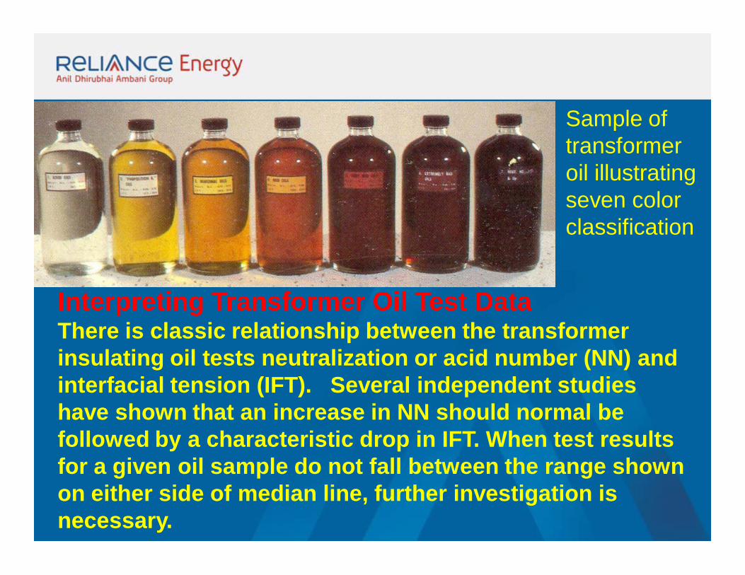
Interpreting Transformer Oil Test DataThere is classic relationship between the transformer insulating oil tests neutralization or acid number (NN) and interfacial tension (IFT). Several independent studies have shown that an increase in NN should normal be followed by a characteristic drop in IFT. When test results for a given oil sample do not fall between the range shown on either side of median line, further investigation is necessary.
Sample of transformer oil illustrating seven color classification
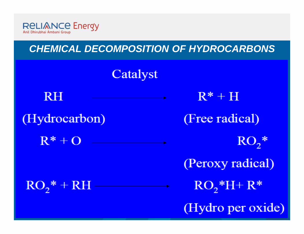
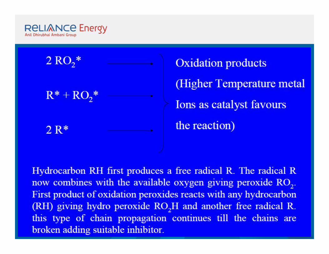
CHEMICAL DECOMPOSITION OF HYDROCARBONS
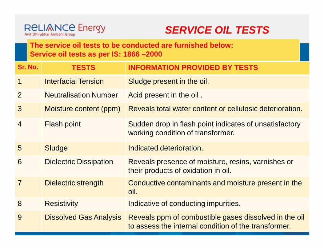
Sr. No. TESTS INFORMATION PROVIDED BY TESTS
1 Interfacial Tension Sludge present in the oil.
2 Neutralisation Number Acid present in the oil .
3 Moisture content (ppm) Reveals total water content or cellulosic deterioration.
4 Flash point Sudden drop in flash point indicates of unsatisfactory working condition of transformer.
5 Sludge Indicated deterioration.
6 Dielectric Dissipation Reveals presence of moisture, resins, varnishes or their products of oxidation in oil.
7 Dielectric strength Conductive contaminants and moisture present in the oil.
8 Resistivity Indicative of conducting impurities.
9 Dissolved Gas Analysis Reveals ppm of combustible gases dissolved in the oil to assess the internal condition of the transformer.
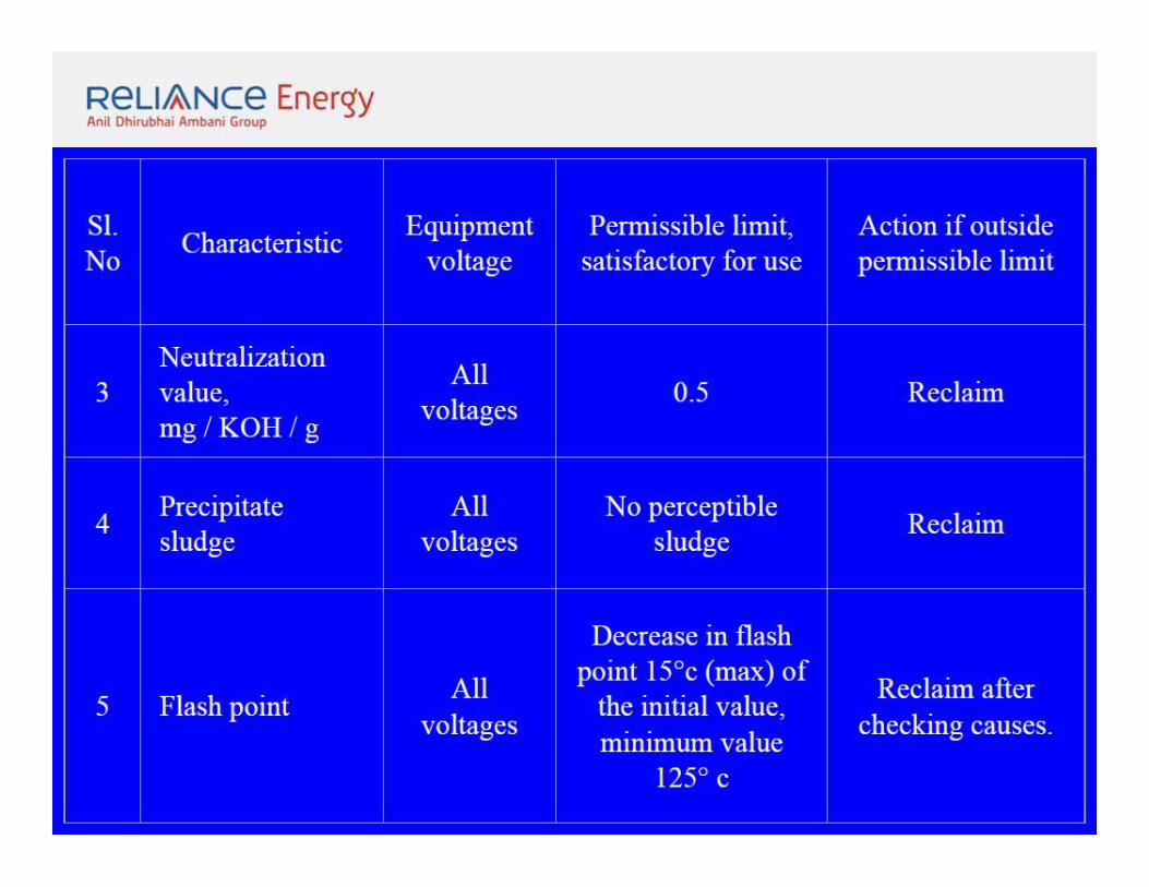
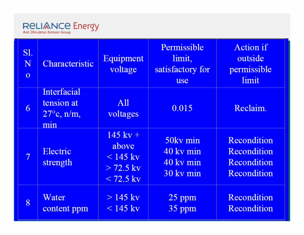
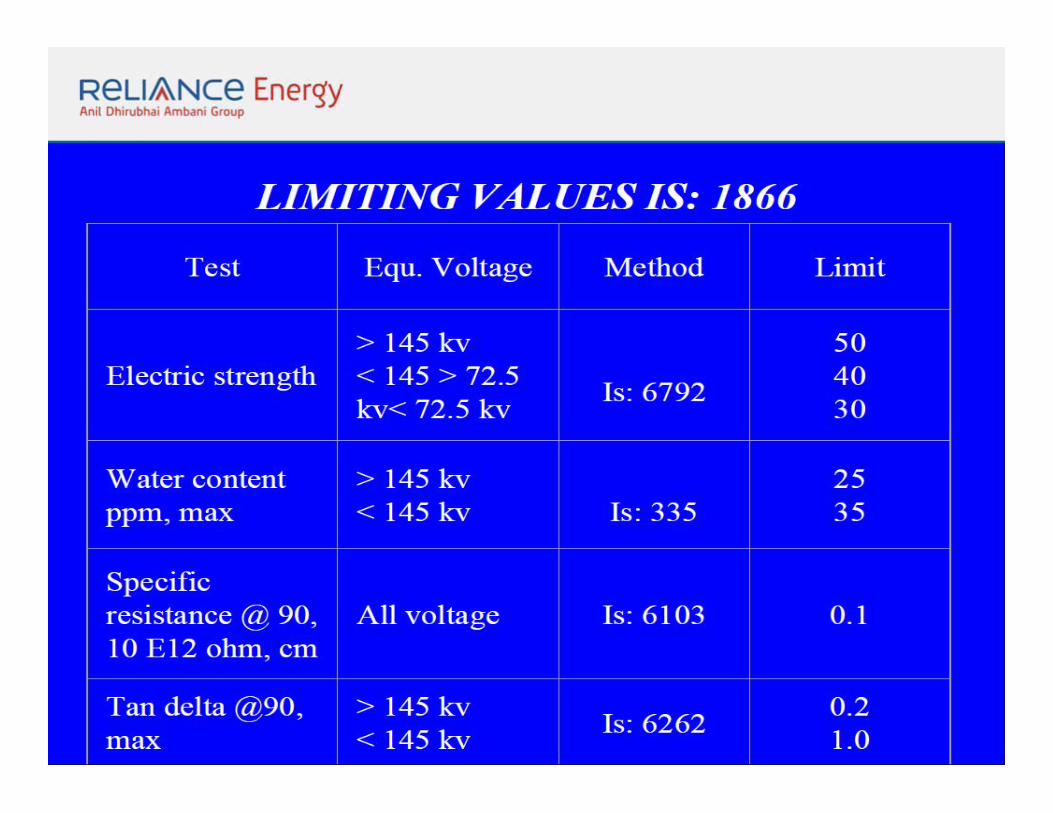
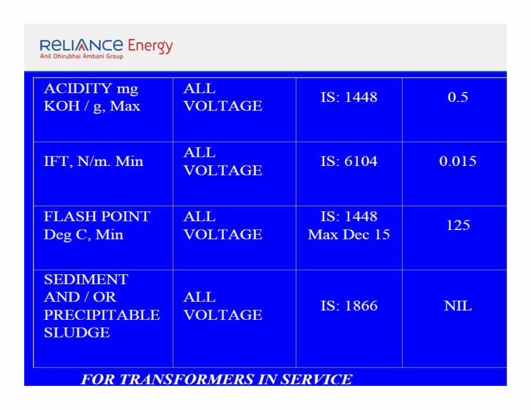
SERVICE OIL TESTSThe service oil tests to be conducted are furnished below:Service oil tests as per IS: 1866 –2000
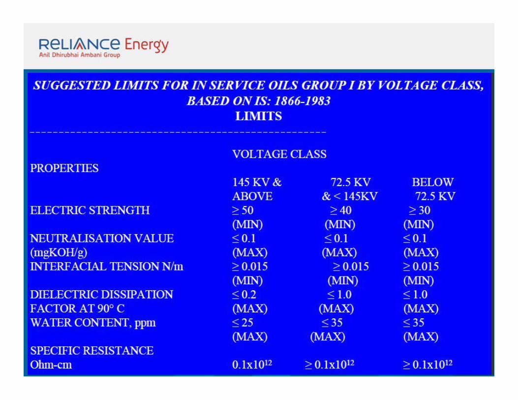
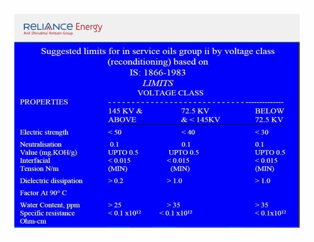
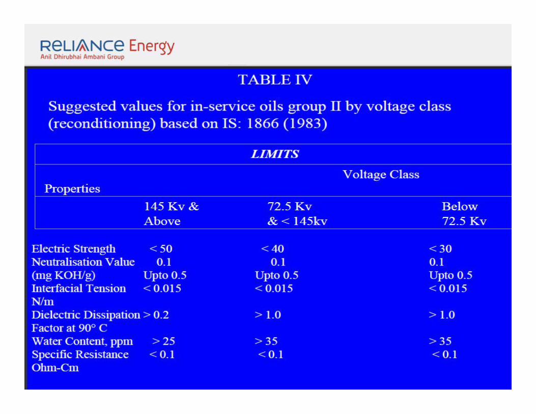
GROUP III OILS:To categorize under group III, the parameters should be
well beyond the limits proposed in table IV. Such oils
should be initially filtered under vacuum and
temperature to verify whether the properties improve or
not. If properties like Dielectric Dissipation Factor,
Interfacial Tension do not improve on filtration, then
there is a case for oil to be replaced.
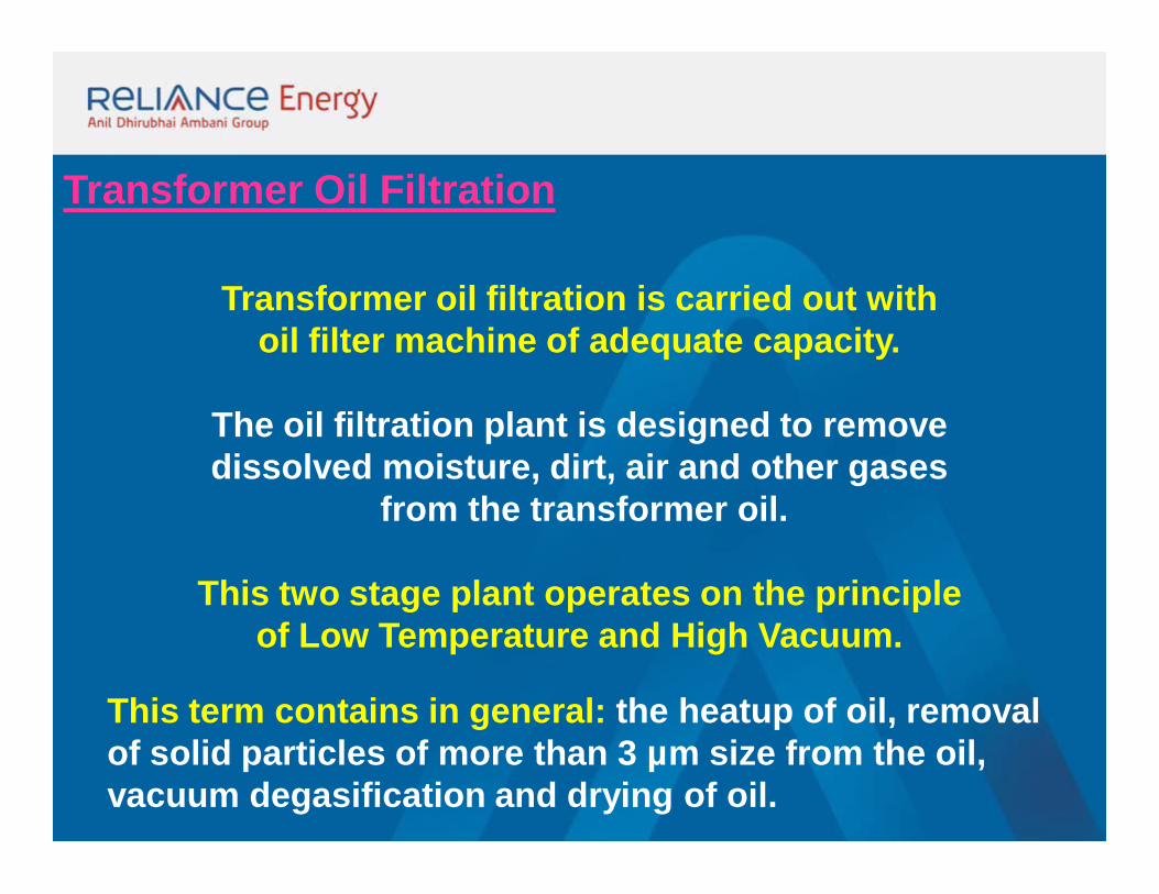
Transformer Oil Filtration
Transformer oil filtration is carried out withoil filter machine of adequate capacity.
The oil filtration plant is designed to remove dissolved moisture, dirt, air and other gases
from the transformer oil.
This two stage plant operates on the principle of Low Temperature and High Vacuum.
This term contains in general: the heatup of oil, removal of solid particles of more than 3 µm size from the oil, vacuum degasification and drying of oil.
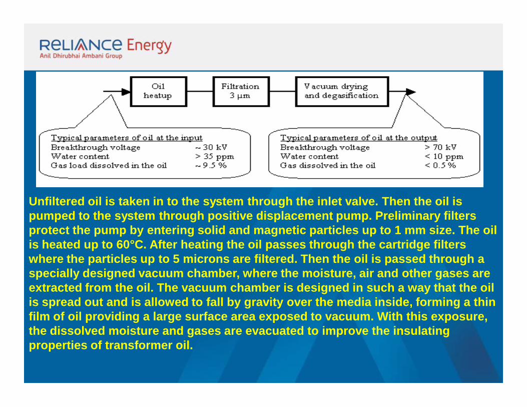
Unfiltered oil is taken in to the system through the inlet valve. Then the oil is pumped to the system through positive displacement pump. Preliminary filters protect the pump by entering solid and magnetic particles up to 1 mm size. The oil is heated up to 60°C. After heating the oil passes through the cartridge filters where the particles up to 5 microns are filtered. Then the oil is passed through a specially designed vacuum chamber, where the moisture, air and other gases are extracted from the oil. The vacuum chamber is designed in such a way that the oil is spread out and is allowed to fall by gravity over the media inside, forming a thin film of oil providing a large surface area exposed to vacuum. With this exposure, the dissolved moisture and gases are evacuated to improve the insulating properties of transformer oil.
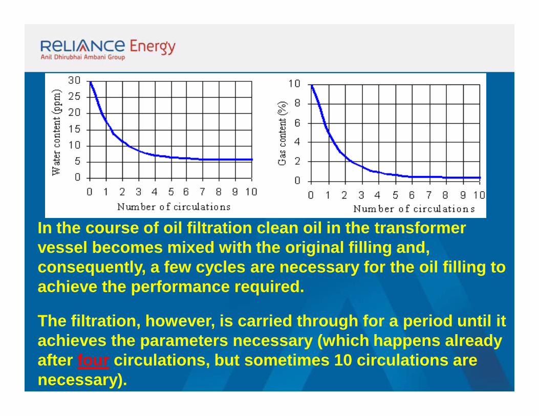
In the course of oil filtration clean oil in the transformer vessel becomes mixed with the original filling and, consequently, a few cycles are necessary for the oil filling to achieve the performance required.
The filtration, however, is carried through for a period until it achieves the parameters necessary (which happens already after four circulations, but sometimes 10 circulations are necessary).
During the filtration solid particles are removed from the transformer oil which entered it as a consequence of wear, chemical and heat decomposition of solid particles, but also by loosened rust and suspended sludges.
During the oil drying it is to reckon with water contained in fixed insulation material. It is known that of the total volume of water in the transformer up to 97 per cent is stored in the wood pulp.
When drying a water affected transformer with the help of oil the curve of water removal from the oil is a significantly different one.
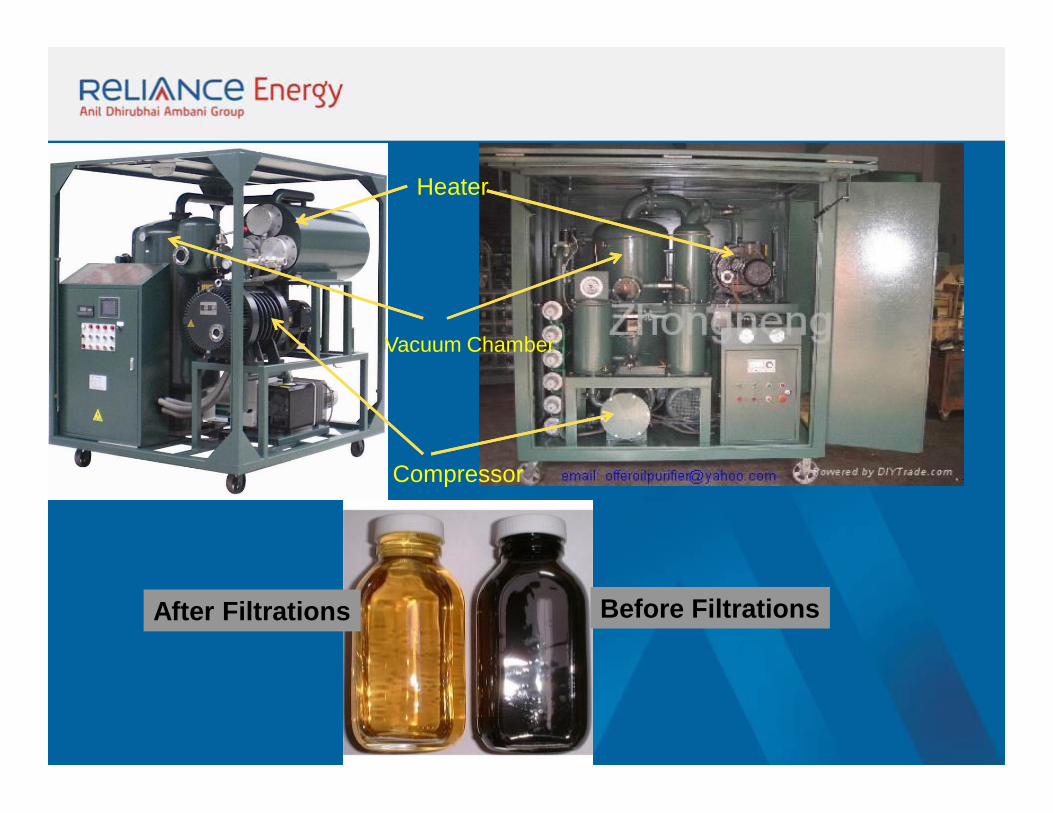
After Filtrations Before Filtrations
Vacuum Chamber
Heater
Compressor
Dehydration of Core Coil assembly of the transformer.
Active part of the transformer is heated and then evacuated for
removal of moisture from the insulation.
Core coil assembly is heated by hot oil circulation or induction heating system.
Drying of Transformer This includes reconditioning of transformer
windings, insulation, gasket sealing and removal of moisture.
Such overhauling is carried out at site with adequate lifting and handling facility.
Transformers are dried using the oil-spray method. The principle consists in heating up the transformer by spraying hot transformer oil on the internal parts of the transformer structure. As soon as the required temperature of the active part of transformer is achieved the vacuum degassing follows.
Vapours of water are sucked off from the machine at the operating pressure of 5 -10 mbar and the temperature of 60 - 80 °C. Normally the capacity of vacuum pumps is 100 - 500 m3 of gases and vapours per hour, which for the initial efficiency of 30 per cent means that up to 2 liters of water are
removed from the transformer in one hour. The efficiency, however, drops gradually down to approx. one tenth of the value, depending on the
moisture degree. The process is then stabilized by hot oil which continues to be sprayed into the internal area of the transformer. Since the
temperature at the point of spraying decreases considerably due to the evaporation of water, and the propagation of heat in vacuum is heavily
constrained, it is necessary to heat up the internal parts of the transformer. This is done by ventilating of the transformer interior and heating up the same with hot oil mist. In such a way about 50 to 100 litres of water are
removed from the transformer during the drying. The time necessary to dry out a transformer is about 10 days.
Drying of transformers
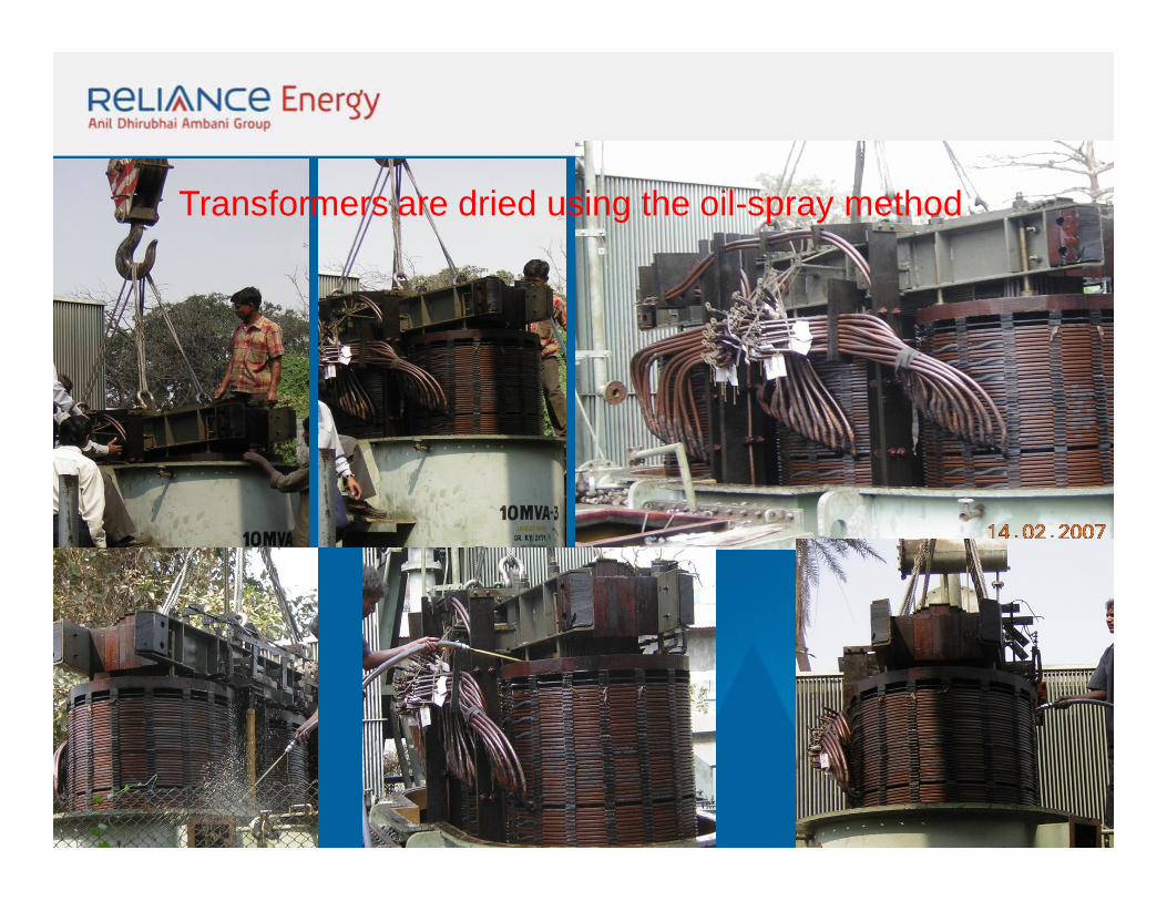
Transformers are dried using the oil-spray method.
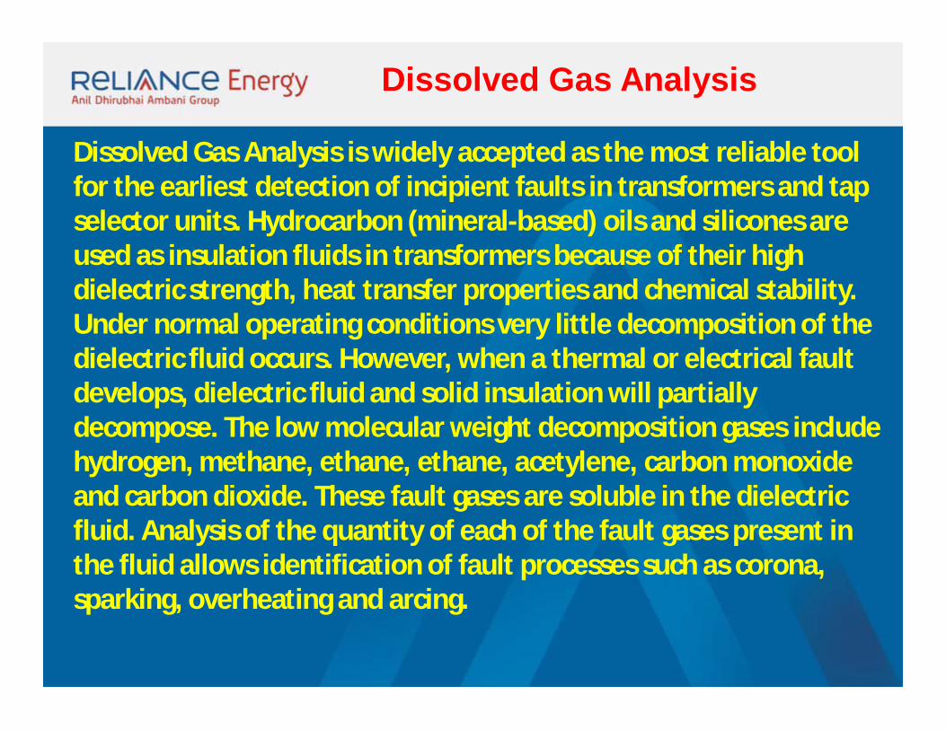
Dissolved Gas Analysis is widely accepted as the most reliable tool for the earliest detection of incipient faults in transformers and tap selector units. Hydrocarbon (mineral-based) oils and silicones are used as insulation fluids in transformers because of their high dielectric strength, heat transfer properties and chemical stability. Under normal operating conditions very little decomposition of the dielectric fluid occurs. However, when a thermal or electrical fault develops, dielectric fluid and solid insulation will partially decompose. The low molecular weight decomposition gases include hydrogen, methane, ethane, ethane, acetylene, carbon monoxide and carbon dioxide. These fault gases are soluble in the dielectric fluid. Analysis of the quantity of each of the fault gases present in the fluid allows identification of fault processes such as corona, sparking, overheating and arcing.
Dissolved Gas Analysis
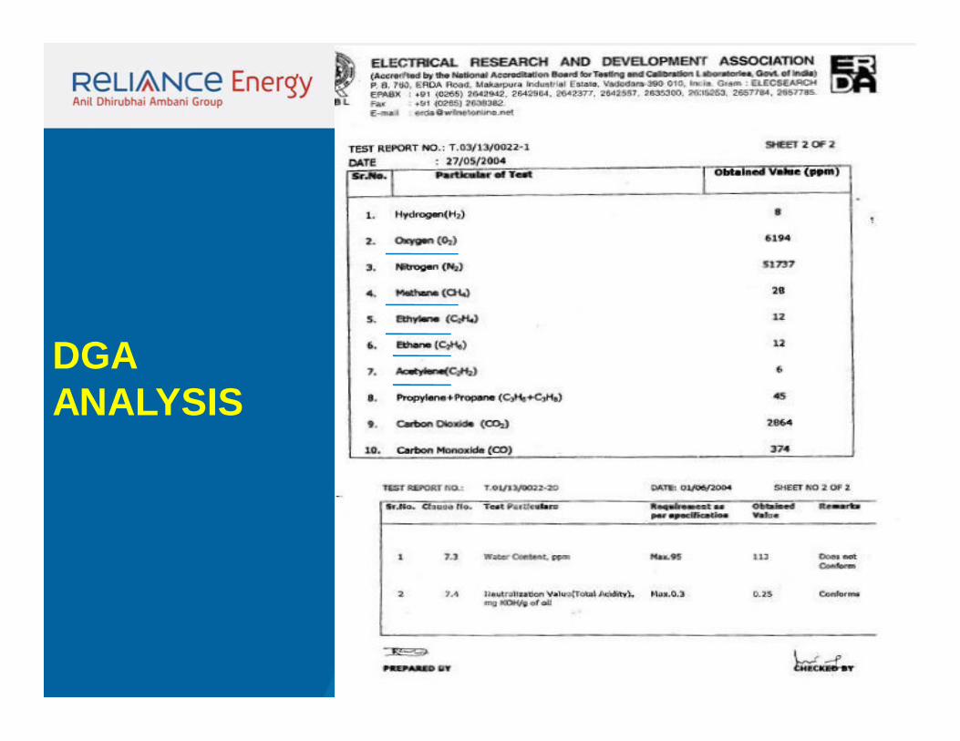
DGA ANALYSIS
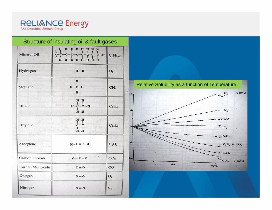
Relative Solubility as a function of Temperature
Structure of insulating oil & fault gases
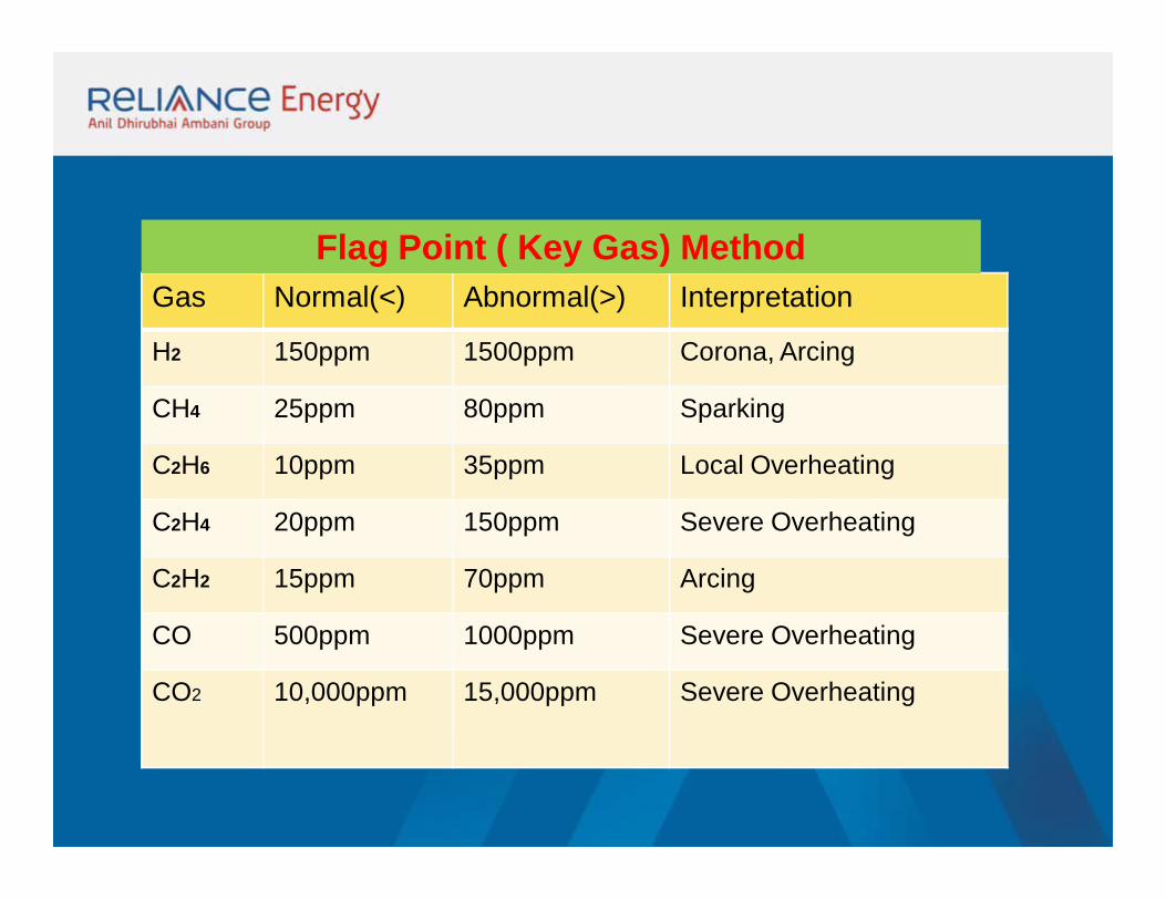
Gas Normal(<) Abnormal(>) Interpretation
H2 150ppm 1500ppm Corona, Arcing
CH4 25ppm 80ppm Sparking
C2H6 10ppm 35ppm Local Overheating
C2H4 20ppm 150ppm Severe Overheating
C2H2 15ppm 70ppm Arcing
CO 500ppm 1000ppm Severe Overheating
CO2 10,000ppm 15,000ppm Severe Overheating
Flag Point ( Key Gas) Method
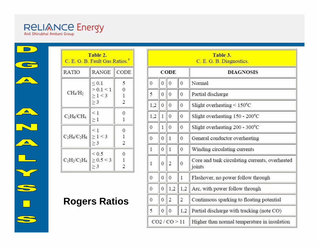
Rogers Ratios
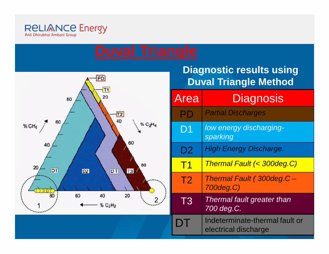
Duval Triangle
Area DiagnosisPD Partial Discharges
D1 low energy discharging-sparking
D2 High Energy Discharge.
T1 Thermal Fault (< 300deg.C)
T2 Thermal Fault ( 300deg.C –700deg.C)
T3 Thermal fault greater than 700 deg.C.
Diagnostic results using Duval Triangle Method
DT Indeterminate-thermal fault or electrical discharge
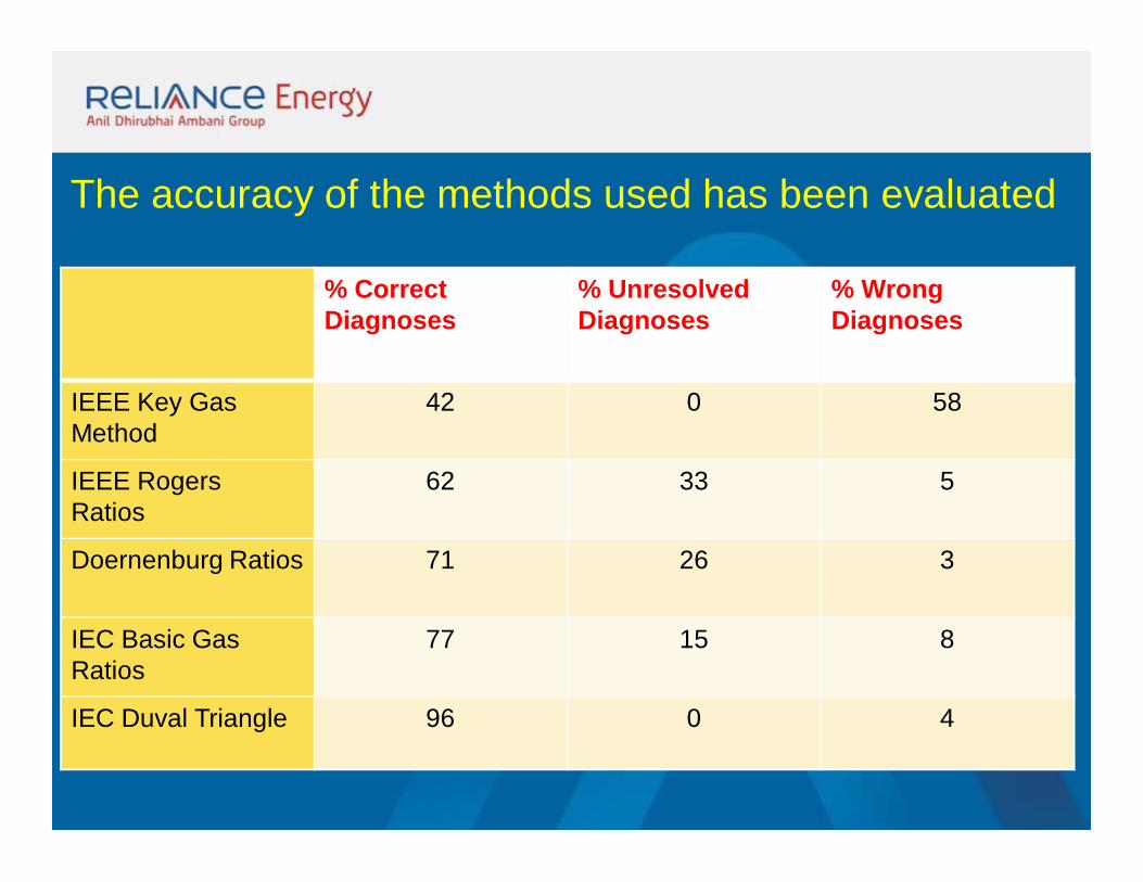
% Correct Diagnoses
% Unresolved Diagnoses
% WrongDiagnoses
IEEE Key Gas Method
42 0 58
IEEE Rogers Ratios
62 33 5
Doernenburg Ratios 71 26 3
IEC Basic Gas Ratios
77 15 8
IEC Duval Triangle 96 0 4
The accuracy of the methods used has been evaluated
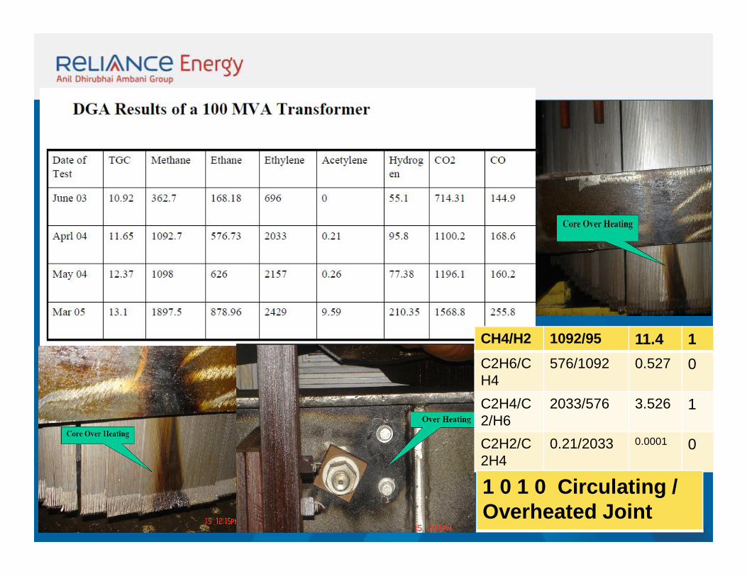
CH4/H2 1092/95 11.4 1C2H6/CH4
576/1092 0.527 0
C2H4/C2/H6
2033/576 3.526 1
C2H2/C2H4
0.21/2033 0.0001 0
1 0 1 0 Circulating / Overheated Joint
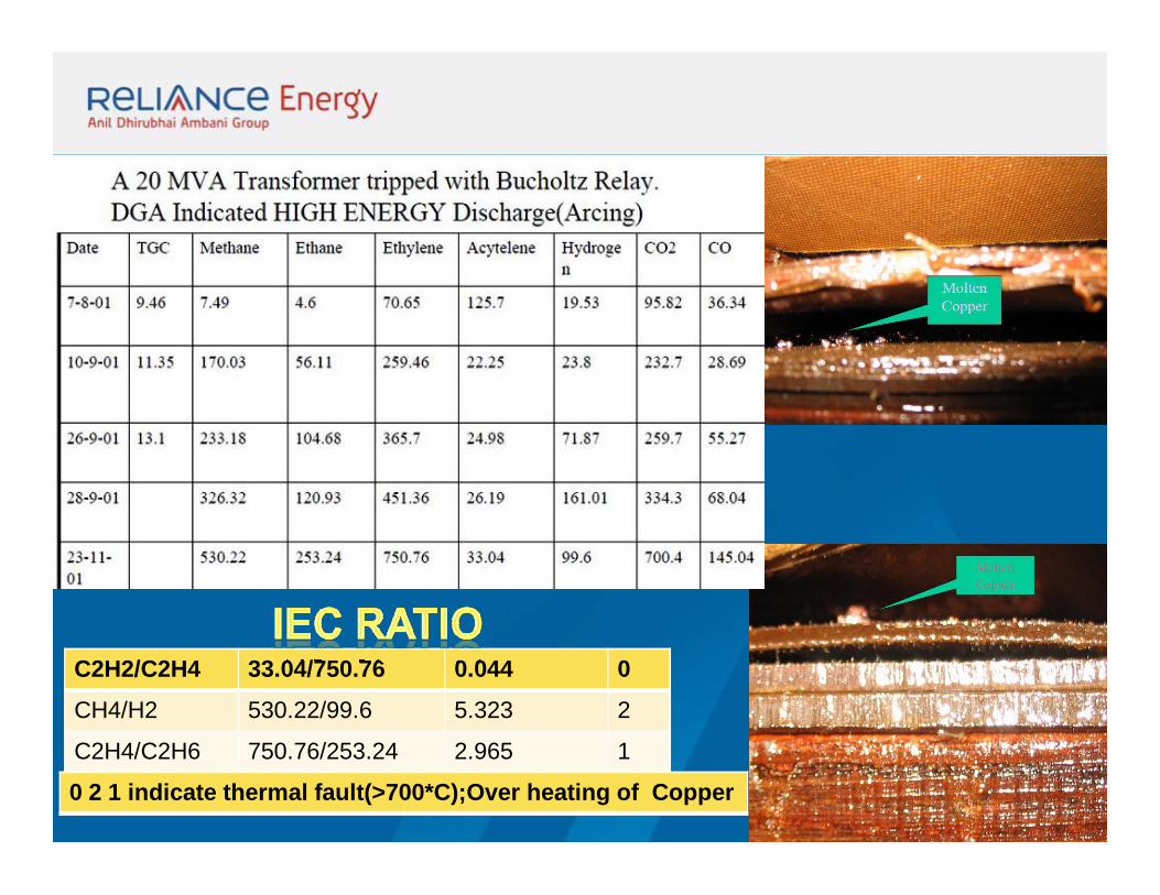
C2H2/C2H4 33.04/750.76 0.044 0
CH4/H2 530.22/99.6 5.323 2
C2H4/C2H6 750.76/253.24 2.965 1
0 2 1 indicate thermal fault(>700*C);Over heating of Copper
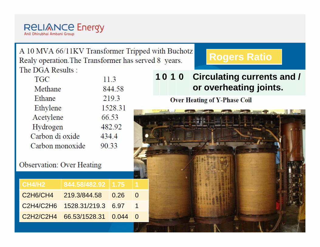
CH4/H2 844.58/482.92 1.75 1C2H6/CH4 219.3/844.58 0.26 0C2H4/C2H6 1528.31/219.3 6.97 1C2H2/C2H4 66.53/1528.31 0.044 0
1 0 1 0 Circulating currents and / or overheating joints.
Rogers Ratio
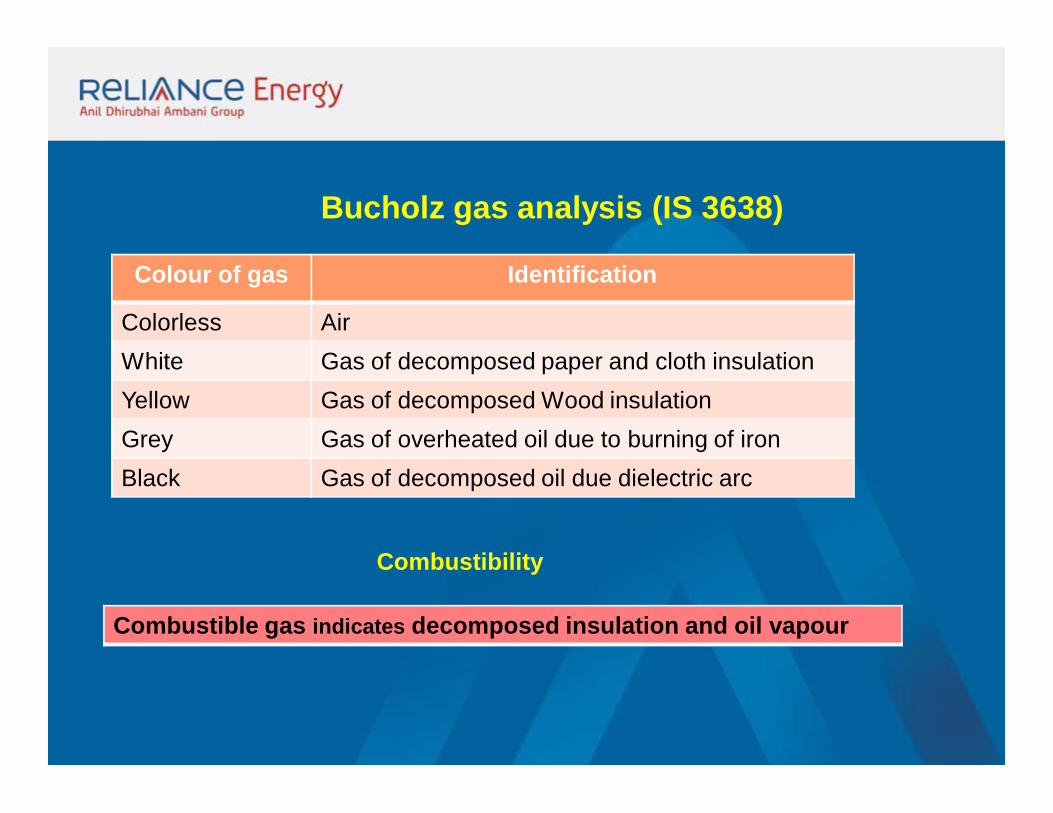
Bucholz gas analysis (IS 3638)
Colour of gas Identification
Colorless AirWhite Gas of decomposed paper and cloth insulationYellow Gas of decomposed Wood insulationGrey Gas of overheated oil due to burning of ironBlack Gas of decomposed oil due dielectric arc
Combustible gas indicates decomposed insulation and oil vapour
Combustibility
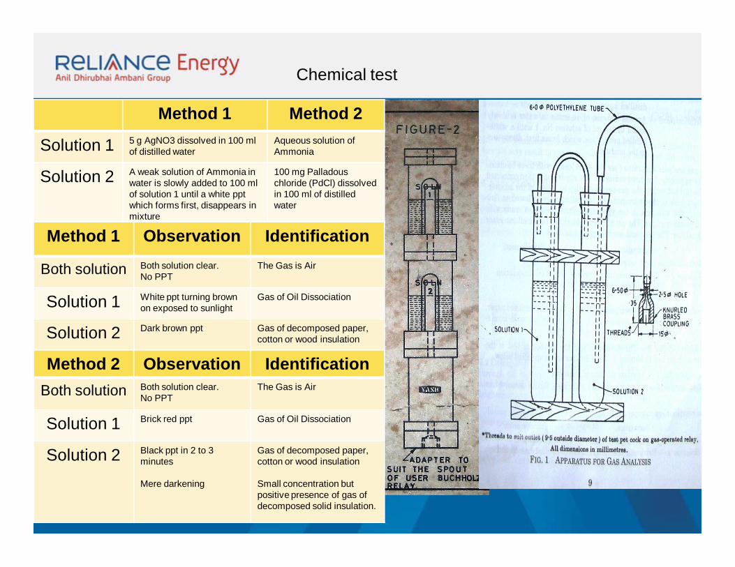
Chemical test
Method 1 Method 2
Solution 1 5 g AgNO3 dissolved in 100 ml of distilled water
Aqueous solution of Ammonia
Solution 2 A weak solution of Ammonia in water is slowly added to 100 ml of solution 1 until a white ppt which forms first, disappears in mixture
100 mg Palladous chloride (PdCl) dissolved in 100 ml of distilled water
Method 1 Observation Identification
Both solution Both solution clear. No PPT
The Gas is Air
Solution 1 White ppt turning brown on exposed to sunlight
Gas of Oil Dissociation
Solution 2 Dark brown ppt Gas of decomposed paper, cotton or wood insulation
Method 2 Observation IdentificationBoth solution Both solution clear.
No PPTThe Gas is Air
Solution 1 Brick red ppt Gas of Oil Dissociation
Solution 2 Black ppt in 2 to 3 minutes
Mere darkening
Gas of decomposed paper, cotton or wood insulation
Small concentration but positive presence of gas of decomposed solid insulation.