transient simulation of the closing of a mems … uk/staticassets/ugm... · transient simulation of...
TRANSCRIPT

1UK users conference, November 9UK users conference, November 9thth 2011, Gaydon, Warwickshire 2011, Gaydon, Warwickshire
RF MEMS TECHNOLOGY PLATFORM FOR CELL PHONESRF MEMS TECHNOLOGY PLATFORM FOR CELL PHONES
Transient simulation of the closing Transient simulation of the closing of a MEMS switch with air gap of a MEMS switch with air gap modeled by FLUID136 elementsmodeled by FLUID136 elementsNicolas LORPHELINSalim TOUATI
22UK users conference, November 9UK users conference, November 9thth 2011, Gaydon, Warwickshire 2011, Gaydon, Warwickshire
OutlineOutline
Presentation of RF MEMS switchesApplicationElectrostatic actuationOhmic / capacitive switches
Delfmems switchfunctioningmodelingprocess flow
Modeling gap closing of FLUID136 elementsDeath of fluidic elementsRough membraneRemaining thin film
Transient simulation of a beam supported on pillars
Transient simulation of delfmems switch
33UK users conference, November 9UK users conference, November 9thth 2011, Gaydon, Warwickshire 2011, Gaydon, Warwickshire
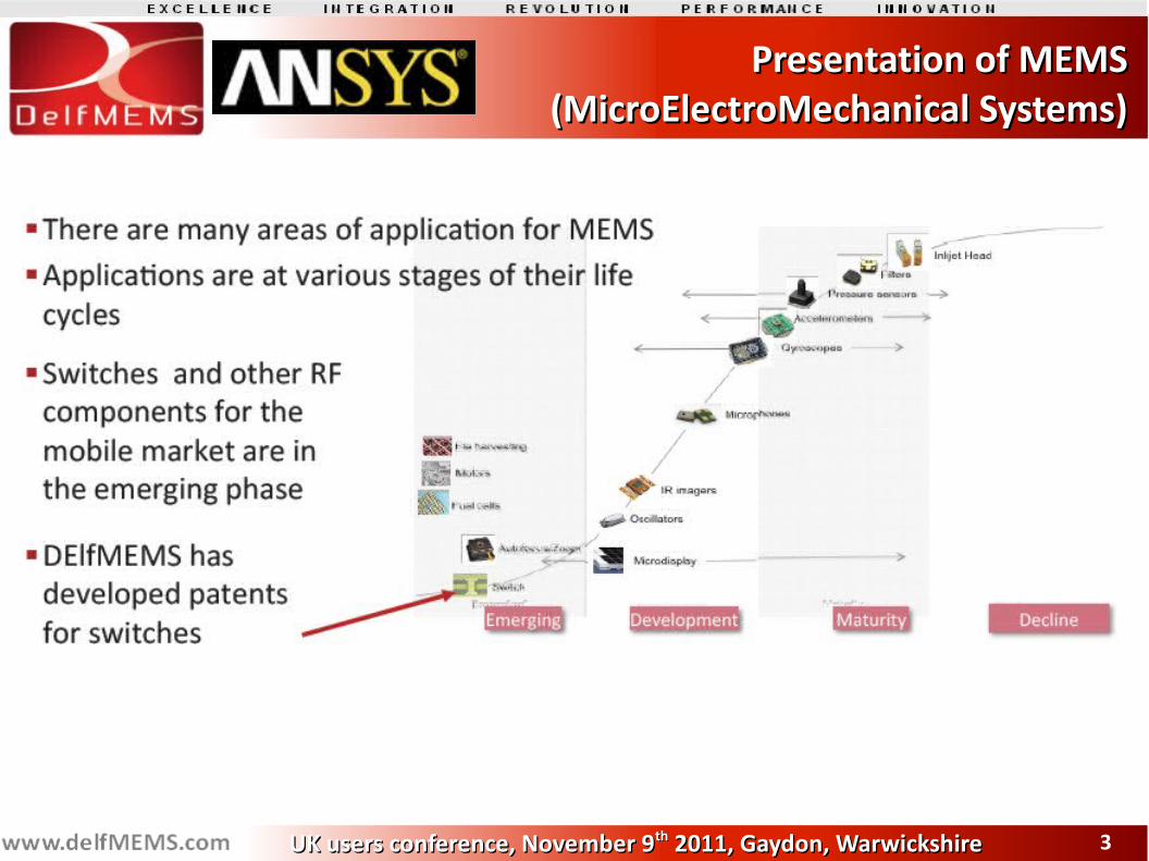
Presentation of MEMSPresentation of MEMS(MicroElectroMechanical Systems)(MicroElectroMechanical Systems)
44UK users conference, November 9UK users conference, November 9thth 2011, Gaydon, Warwickshire 2011, Gaydon, Warwickshire
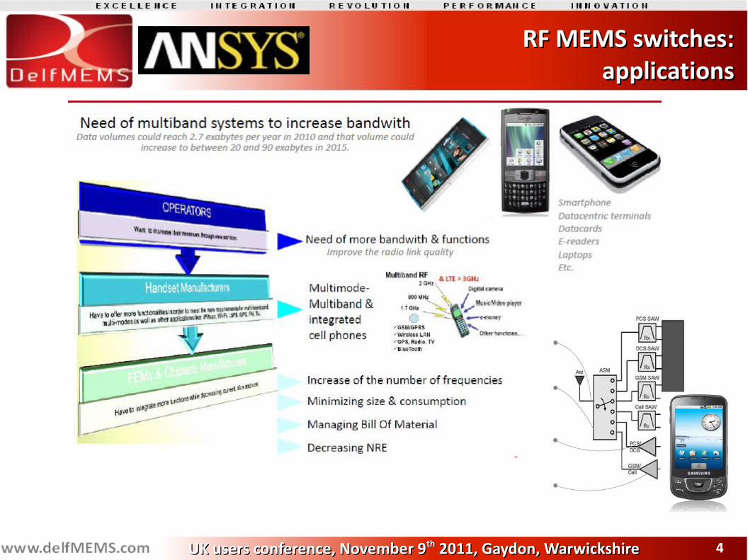
RF MEMS switches:RF MEMS switches: applications applications
55UK users conference, November 9UK users conference, November 9thth 2011, Gaydon, Warwickshire 2011, Gaydon, Warwickshire
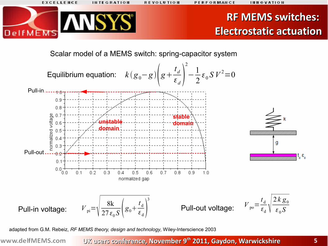
RF MEMS switches: RF MEMS switches: Electrostatic actuationElectrostatic actuation
Pull-in
Pull-out
stable domainunstable
domain
Scalar model of a MEMS switch: spring-capacitor system
k g 0−g g tdd 2
−120 S V
2=0Equilibrium equation:
Pull-in voltage: V pi= 8k270S g0 t dd
3
Pull-out voltage: V po=t dd 2k g00S
adapted from G.M. Rebeiz, RF MEMS theory, design and technology, Wiley-Interscience 2003
66UK users conference, November 9UK users conference, November 9thth 2011, Gaydon, Warwickshire 2011, Gaydon, Warwickshire
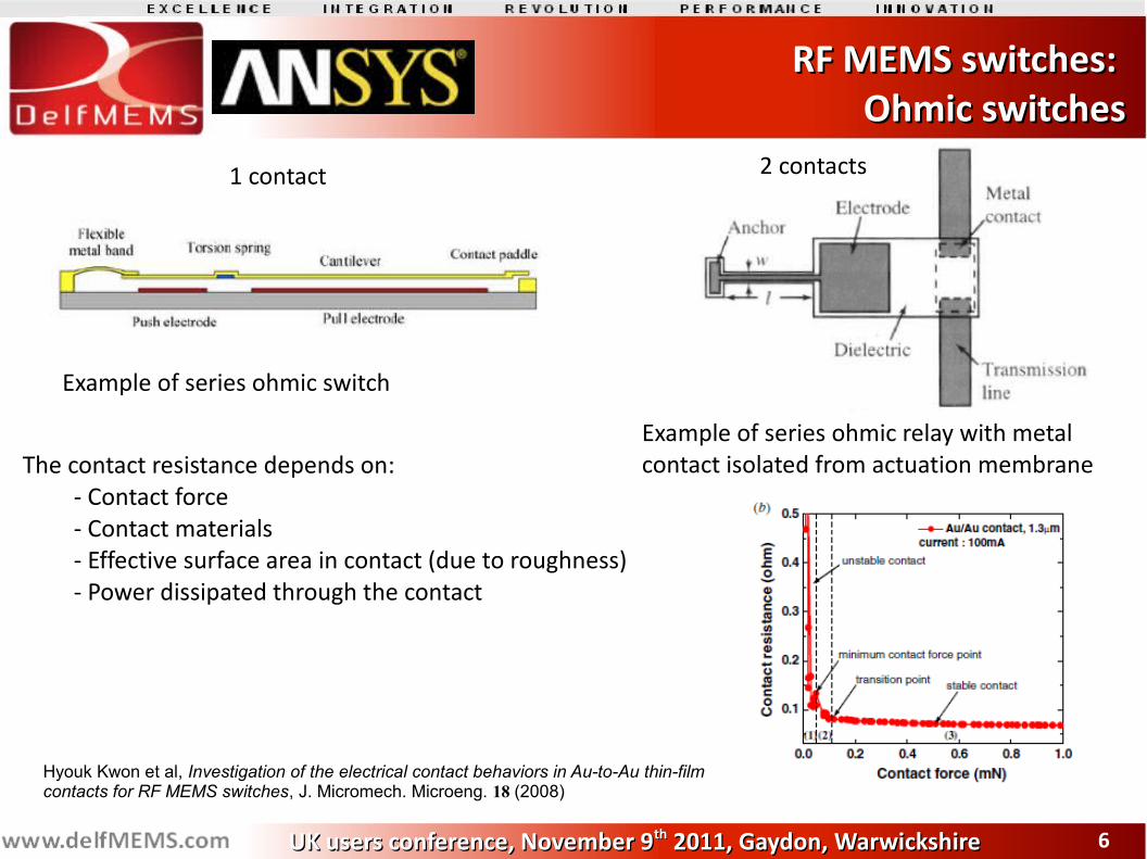
Example of series ohmic switch
Example of series ohmic relay with metal contact isolated from actuation membrane
1 contact 2 contacts
The contact resistance depends on:- Contact force- Contact materials- Effective surface area in contact (due to roughness)- Power dissipated through the contact
Hyouk Kwon et al, Investigation of the electrical contact behaviors in Au-to-Au thin-film contacts for RF MEMS switches, J. Micromech. Microeng. 18 (2008)
RF MEMS switches: RF MEMS switches: Ohmic switchesOhmic switches
77UK users conference, November 9UK users conference, November 9thth 2011, Gaydon, Warwickshire 2011, Gaydon, Warwickshire
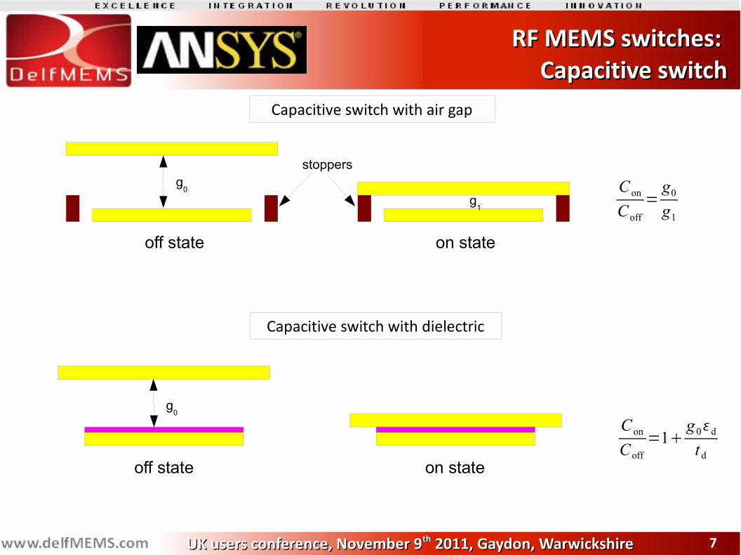
g0
g1
off state on state
ConCoff
=g0g1
Capacitive switch with air gap
stoppers
Capacitive switch with dielectric
g0
off state on state
ConCoff
=1g0dt d
RF MEMS switches: RF MEMS switches: Capacitive switchCapacitive switch
88UK users conference, November 9UK users conference, November 9thth 2011, Gaydon, Warwickshire 2011, Gaydon, Warwickshire
Delfmems switchDelfmems switch
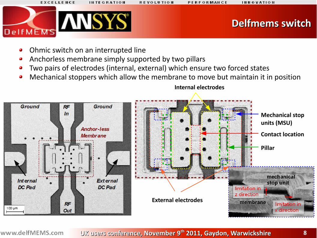
Ohmic switch on an interrupted lineAnchorless membrane simply supported by two pillarsTwo pairs of electrodes (internal, external) which ensure two forced statesMechanical stoppers which allow the membrane to move but maintain it in position
Contact location
Mechanical stop units (MSU)
Pillar
Internal electrodes
External electrodes
99UK users conference, November 9UK users conference, November 9thth 2011, Gaydon, Warwickshire 2011, Gaydon, Warwickshire
Delfmems switchDelfmems switch
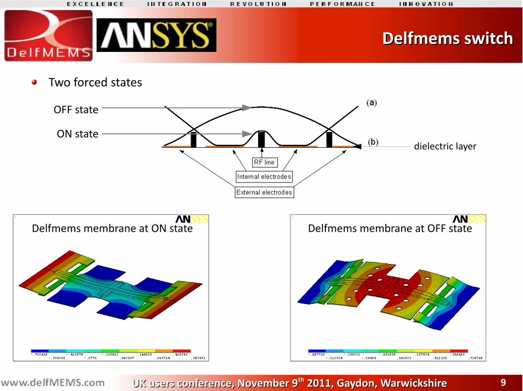
Two forced states
OFF state
ON statedielectric layer
Delfmems membrane at ON state Delfmems membrane at OFF state
1010UK users conference, November 9UK users conference, November 9thth 2011, Gaydon, Warwickshire 2011, Gaydon, Warwickshire
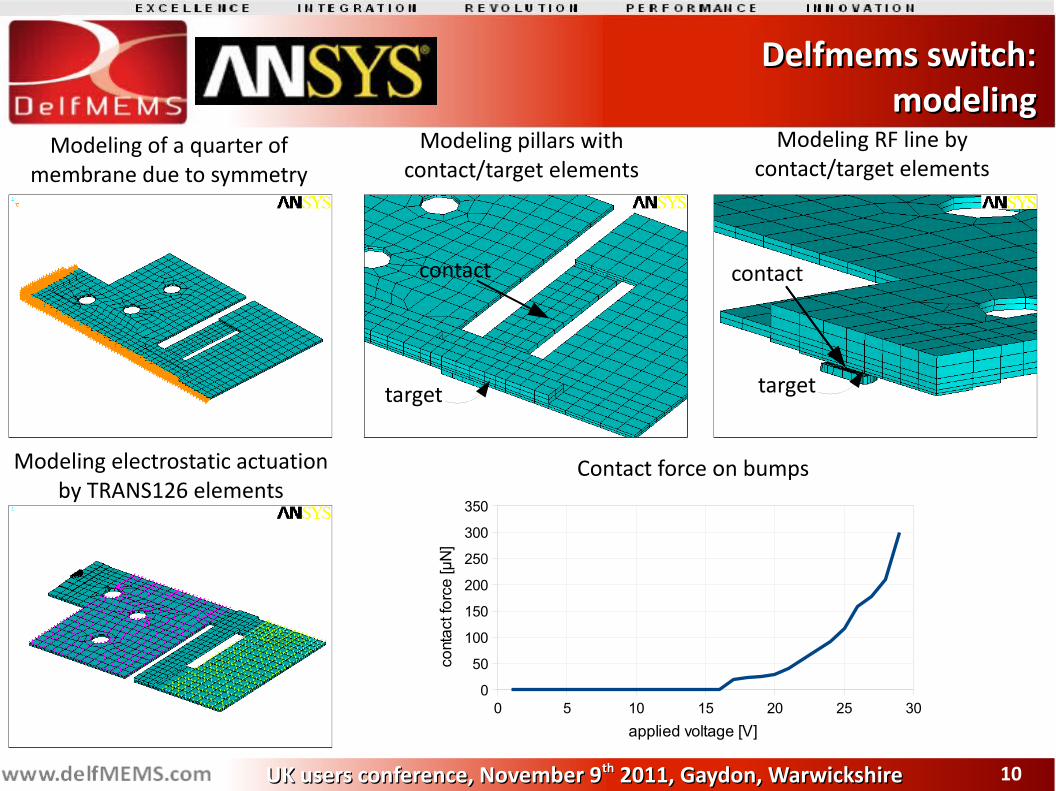
Delfmems switch:Delfmems switch:modelingmodeling
Modeling of a quarter of membrane due to symmetry
Modeling pillars with contact/target elements
Modeling RF line by contact/target elements
contact
target
contact
target
Modeling electrostatic actuation by TRANS126 elements
0 5 10 15 20 25 300
50
100
150
200
250
300
350
applied voltage [V]
cont
act f
orce
[µN
]Contact force on bumps
1111UK users conference, November 9UK users conference, November 9thth 2011, Gaydon, Warwickshire 2011, Gaydon, Warwickshire
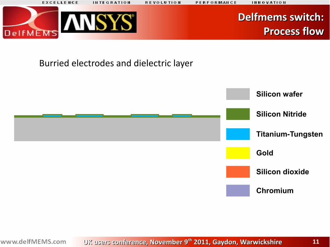
Delfmems switch:Delfmems switch:Process flowProcess flow
Silicon wafer
Silicon Nitride
Titanium-Tungsten
Gold
Silicon dioxide
Chromium
Burried electrodes and dielectric layer
1212UK users conference, November 9UK users conference, November 9thth 2011, Gaydon, Warwickshire 2011, Gaydon, Warwickshire
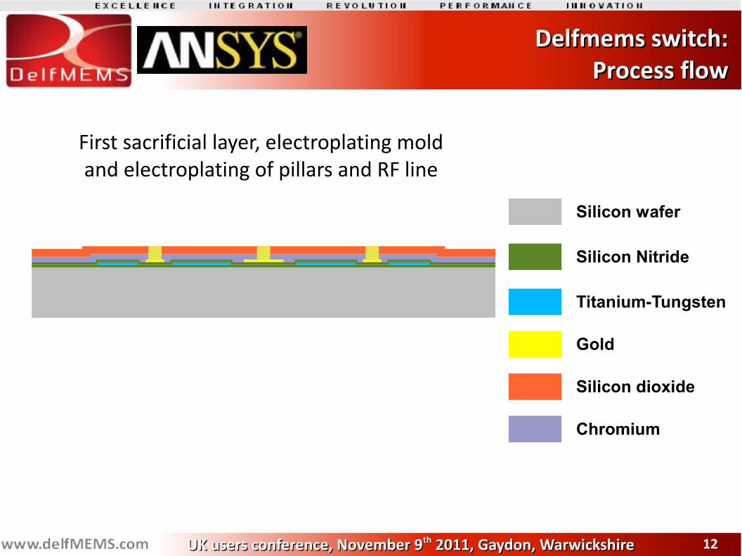
Delfmems switch:Delfmems switch:Process flowProcess flow
First sacrificial layer, electroplating moldand electroplating of pillars and RF line
Silicon wafer
Silicon Nitride
Titanium-Tungsten
Gold
Silicon dioxide
Chromium
1313UK users conference, November 9UK users conference, November 9thth 2011, Gaydon, Warwickshire 2011, Gaydon, Warwickshire
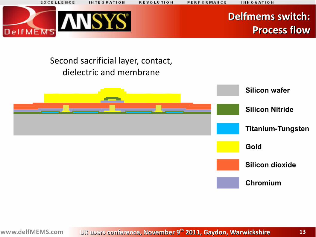
Delfmems switch:Delfmems switch:Process flowProcess flow
Second sacrificial layer, contact,dielectric and membrane
Silicon wafer
Silicon Nitride
Titanium-Tungsten
Gold
Silicon dioxide
Chromium
1414UK users conference, November 9UK users conference, November 9thth 2011, Gaydon, Warwickshire 2011, Gaydon, Warwickshire
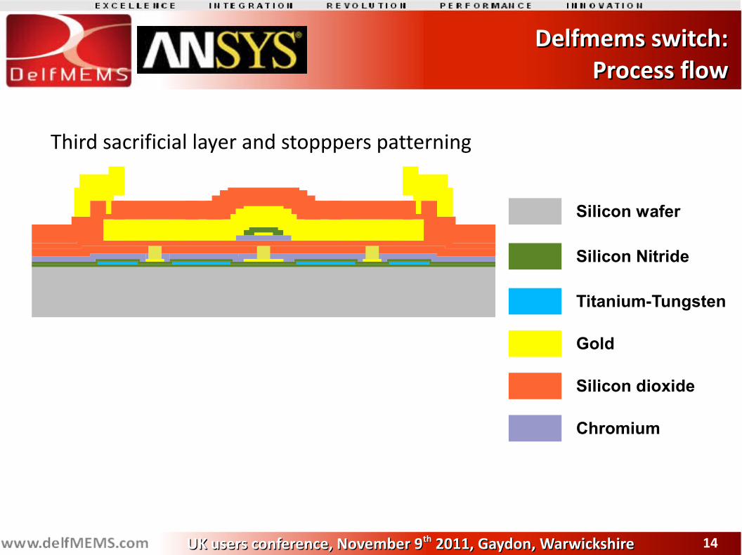
Delfmems switch:Delfmems switch:Process flowProcess flow
Third sacrificial layer and stopppers patterning
Silicon wafer
Silicon Nitride
Titanium-Tungsten
Gold
Silicon dioxide
Chromium
1515UK users conference, November 9UK users conference, November 9thth 2011, Gaydon, Warwickshire 2011, Gaydon, Warwickshire
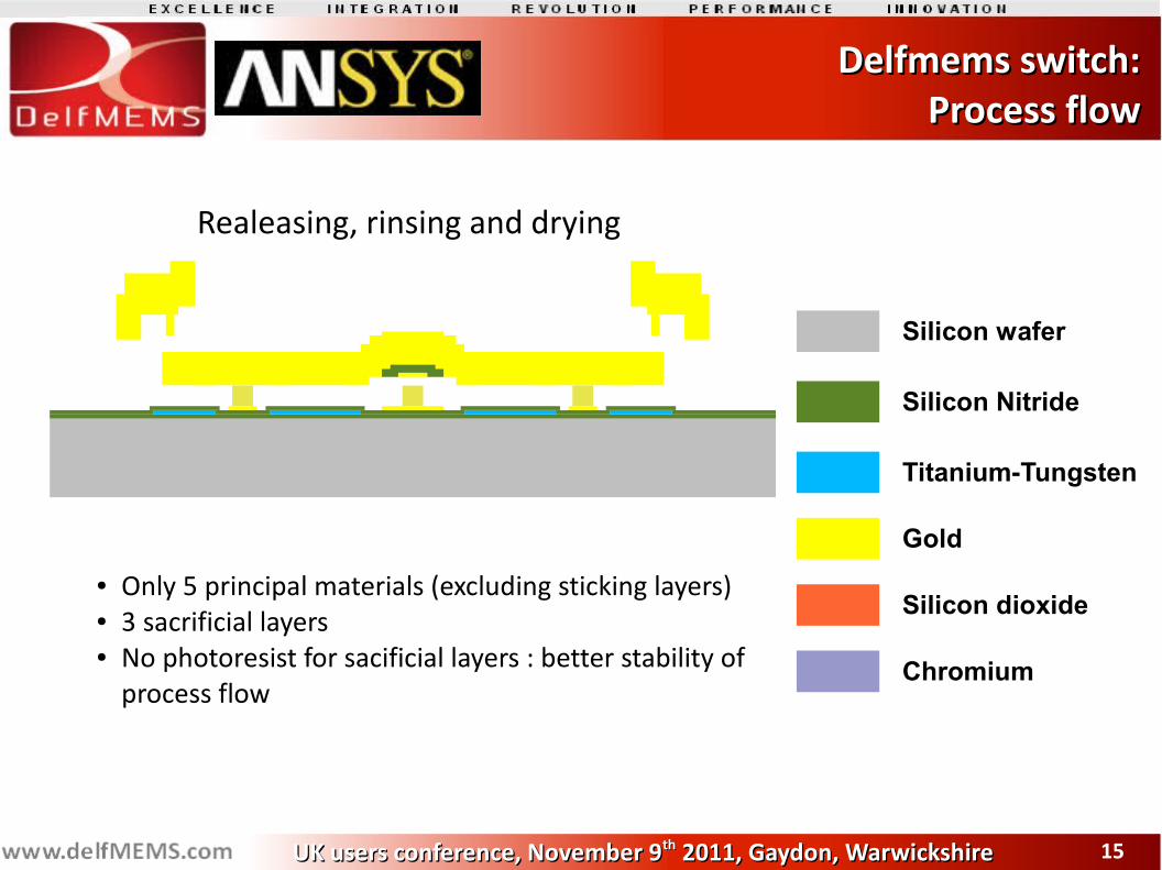
Delfmems switch:Delfmems switch:Process flowProcess flow
Realeasing, rinsing and drying
● Only 5 principal materials (excluding sticking layers)● 3 sacrificial layers● No photoresist for sacificial layers : better stability of
process flow
Silicon wafer
Silicon Nitride
Titanium-Tungsten
Gold
Silicon dioxide
Chromium
1616UK users conference, November 9UK users conference, November 9thth 2011, Gaydon, Warwickshire 2011, Gaydon, Warwickshire
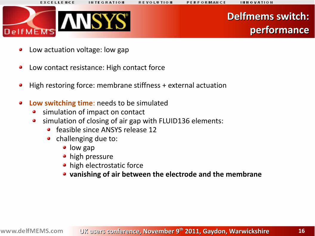
Delfmems switch:Delfmems switch:performanceperformance
Low actuation voltage: low gap
Low contact resistance: High contact force
High restoring force: membrane stiffness + external actuation
Low switching time: needs to be simulatedsimulation of impact on contactsimulation of closing of air gap with FLUID136 elements:
feasible since ANSYS release 12challenging due to:
low gap high pressurehigh electrostatic forcevanishing of air between the electrode and the membrane
1717UK users conference, November 9UK users conference, November 9thth 2011, Gaydon, Warwickshire 2011, Gaydon, Warwickshire
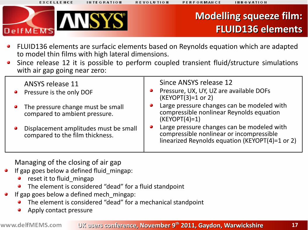
Modelling squeeze film:Modelling squeeze film: FLUID136 elements FLUID136 elements
ANSYS release 11Pressure is the only DOF
The pressure change must be small compared to ambient pressure.
Displacement amplitudes must be small compared to the film thickness.
Since ANSYS release 12Pressure, UX, UY, UZ are available DOFs (KEYOPT(3)=1 or 2)Large pressure changes can be modeled with compressible nonlinear Reynolds equation (KEYOPT(4)=1)Large pressure changes can be modeled with compressible nonlinear or incompressible linearized Reynolds equation (KEYOPT(4)=1 or 2)
FLUID136 elements are surfacic elements based on Reynolds equation which are adapted to model thin films with high lateral dimensions.Since release 12 it is possible to perform coupled transient fluid/structure simulations with air gap going near zero:
Managing of the closing of air gapIf gap goes below a defined fluid_mingap:
reset it to fluid_mingapThe element is considered “dead” for a fluid standpoint
If gap goes below a defined mech_mingap:The element is considered “dead” for a mechanical standpointApply contact pressure
1818UK users conference, November 9UK users conference, November 9thth 2011, Gaydon, Warwickshire 2011, Gaydon, Warwickshire
Simulation of gap closing:Simulation of gap closing:Death of fluid elements Death of fluid elements
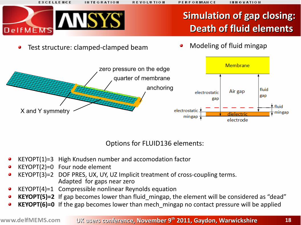
Test structure: clamped-clamped beam Modeling of fluid mingap
quarter of membraneanchoring
X and Y symmetry
zero pressure on the edge
Options for FLUID136 elements:
KEYOPT(1)=3 High Knudsen number and accomodation factorKEYOPT(2)=0 Four node elementKEYOPT(3)=2 DOF PRES, UX, UY, UZ Implicit treatment of cross-coupling terms.
Adapted for gaps near zeroKEYOPT(4)=1 Compressible nonlinear Reynolds equationKEYOPT(5)=2 If gap becomes lower than fluid_mingap, the element will be considered as “dead”KEYOPT(6)=0 If the gap becomes lower than mech_mingap no contact pressure will be applied
1919UK users conference, November 9UK users conference, November 9thth 2011, Gaydon, Warwickshire 2011, Gaydon, Warwickshire
Simulation of gap closing:Simulation of gap closing:Death of fluid elements Death of fluid elements
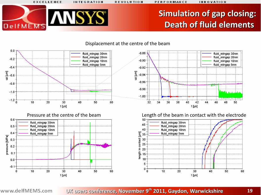
Displacement at the centre of the beam
Length of the beam in contact with the electrodePressure at the centre of the beam
2020UK users conference, November 9UK users conference, November 9thth 2011, Gaydon, Warwickshire 2011, Gaydon, Warwickshire
Simulation of gap closing:Simulation of gap closing:Death of fluid elements Death of fluid elements
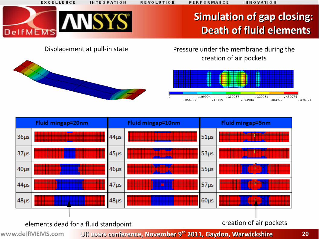
elements dead for a fluid standpoint creation of air pockets
Pressure under the membrane during the creation of air pockets
Displacement at pull-in state
2121UK users conference, November 9UK users conference, November 9thth 2011, Gaydon, Warwickshire 2011, Gaydon, Warwickshire
Simulation of gap closing:Simulation of gap closing:Death of fluid elements Death of fluid elements
Fluid death of FLUID136 elements is not satisfactory:
Abrupt drop of pressure
Abrupt acceleration of the membrane
Highly dependent on the choice of fluid_mingap
Creation of air pockets
2222UK users conference, November 9UK users conference, November 9thth 2011, Gaydon, Warwickshire 2011, Gaydon, Warwickshire
Simulation of gap closing:Simulation of gap closing:Roughness Roughness
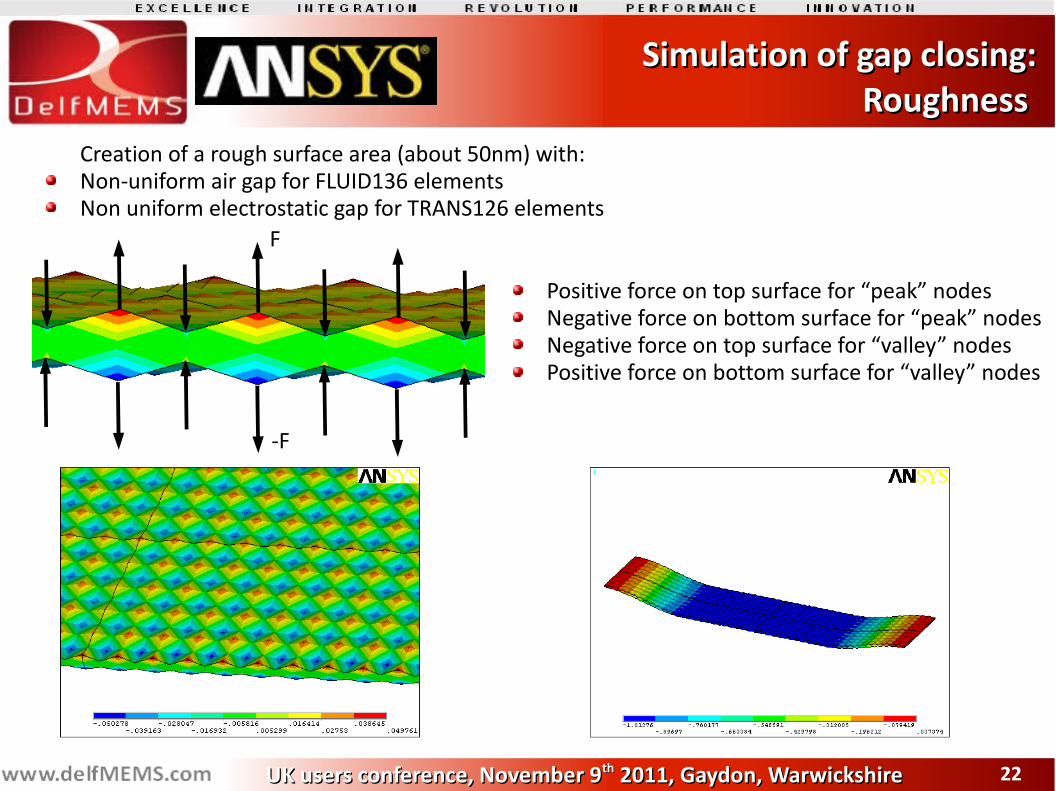
Creation of a rough surface area (about 50nm) with:Non-uniform air gap for FLUID136 elementsNon uniform electrostatic gap for TRANS126 elements
F
-F
Positive force on top surface for “peak” nodesNegative force on bottom surface for “peak” nodesNegative force on top surface for “valley” nodesPositive force on bottom surface for “valley” nodes
2323UK users conference, November 9UK users conference, November 9thth 2011, Gaydon, Warwickshire 2011, Gaydon, Warwickshire
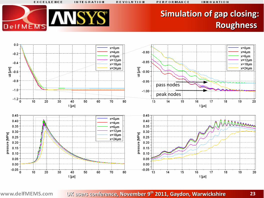
Simulation of gap closing:Simulation of gap closing:Roughness Roughness
peak nodes
pass nodes
2424UK users conference, November 9UK users conference, November 9thth 2011, Gaydon, Warwickshire 2011, Gaydon, Warwickshire
Simulation of gap closing:Simulation of gap closing:Remaining fluid gap Remaining fluid gap
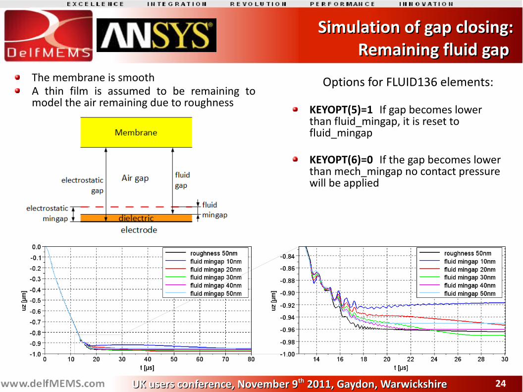
Options for FLUID136 elements:
KEYOPT(5)=1 If gap becomes lower than fluid_mingap, it is reset to fluid_mingap
KEYOPT(6)=0 If the gap becomes lower than mech_mingap no contact pressure will be applied
The membrane is smoothA thin film is assumed to be remaining to model the air remaining due to roughness
2525UK users conference, November 9UK users conference, November 9thth 2011, Gaydon, Warwickshire 2011, Gaydon, Warwickshire
Simulation of gap closing:Simulation of gap closing:Remaining fluid gap Remaining fluid gap
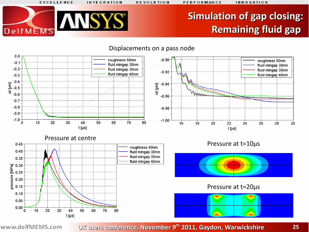
Displacements on a pass node
Pressure at centrePressure at t=10µs
Pressure at t=20µs
2626UK users conference, November 9UK users conference, November 9thth 2011, Gaydon, Warwickshire 2011, Gaydon, Warwickshire
Simulation of gap closing:Simulation of gap closing:Remaining fluid gap Remaining fluid gap
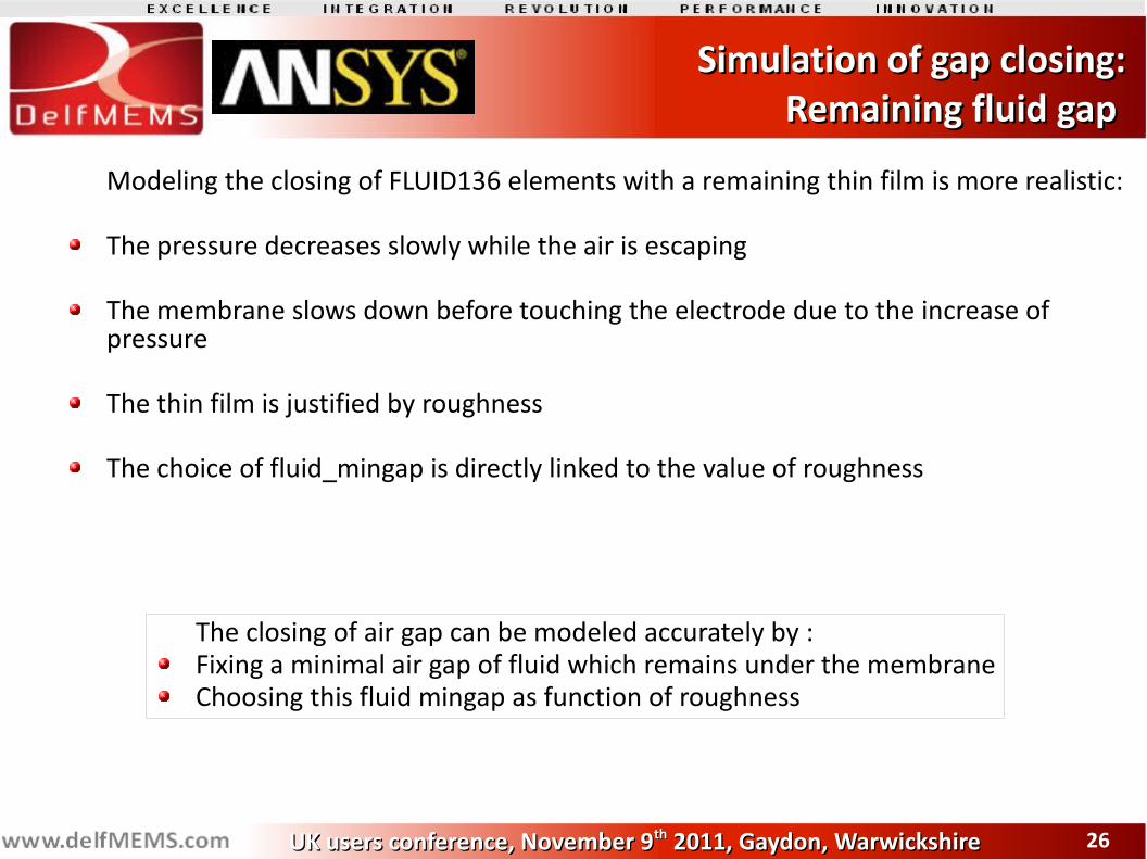
Modeling the closing of FLUID136 elements with a remaining thin film is more realistic:
The pressure decreases slowly while the air is escaping
The membrane slows down before touching the electrode due to the increase of pressure
The thin film is justified by roughness
The choice of fluid_mingap is directly linked to the value of roughness
The closing of air gap can be modeled accurately by :Fixing a minimal air gap of fluid which remains under the membraneChoosing this fluid mingap as function of roughness
2727UK users conference, November 9UK users conference, November 9thth 2011, Gaydon, Warwickshire 2011, Gaydon, Warwickshire
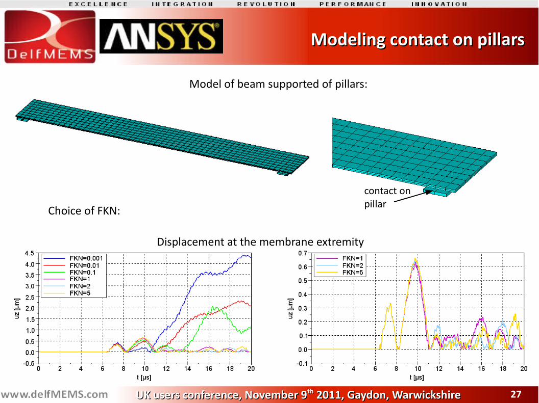
Modeling contact on pillars Modeling contact on pillars
Model of beam supported of pillars:
contact on pillar
Choice of FKN:
Displacement at the membrane extremity
2828UK users conference, November 9UK users conference, November 9thth 2011, Gaydon, Warwickshire 2011, Gaydon, Warwickshire
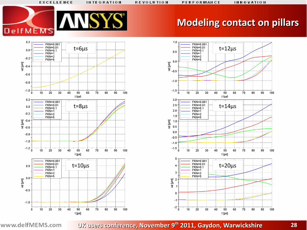
Modeling contact on pillars Modeling contact on pillars
t=6µs
t=8µs
t=10µs
t=12µs
t=14µs
t=20µs
2929UK users conference, November 9UK users conference, November 9thth 2011, Gaydon, Warwickshire 2011, Gaydon, Warwickshire
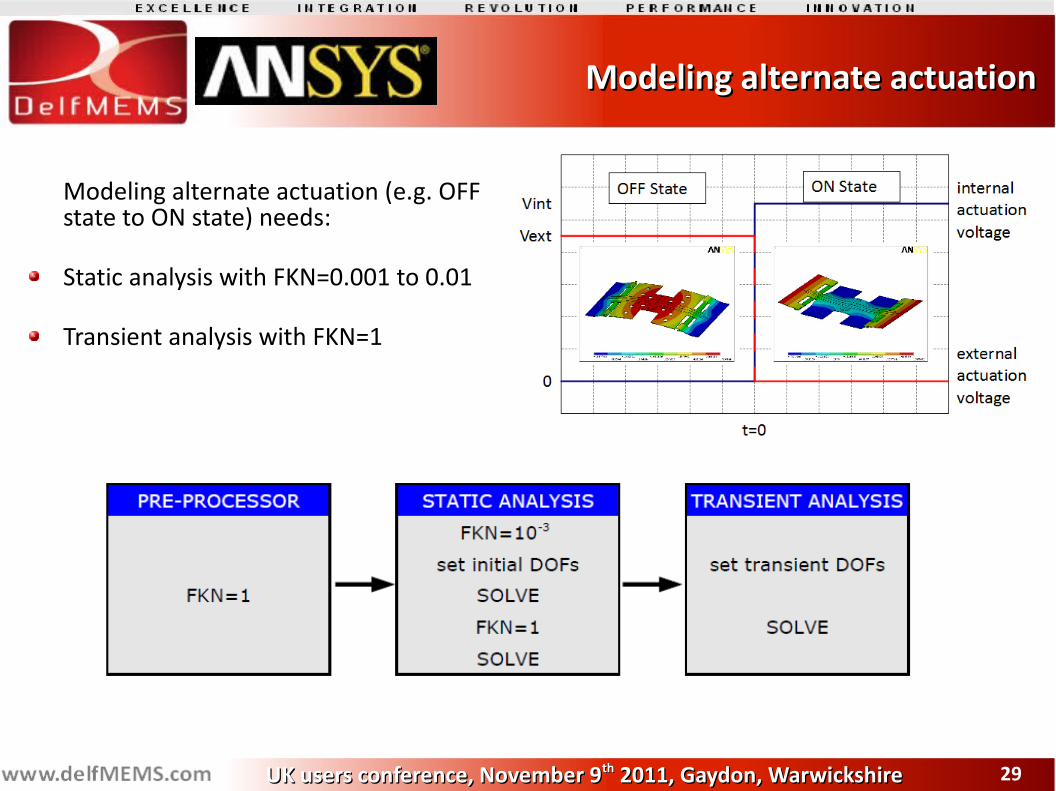
Modeling alternate actuationModeling alternate actuation
Modeling alternate actuation (e.g. OFF state to ON state) needs:
Static analysis with FKN=0.001 to 0.01
Transient analysis with FKN=1
3030UK users conference, November 9UK users conference, November 9thth 2011, Gaydon, Warwickshire 2011, Gaydon, Warwickshire
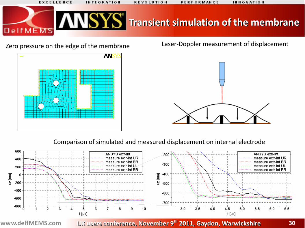
Transient simulation of the membraneTransient simulation of the membrane
Zero pressure on the edge of the membrane Laser-Doppler measurement of displacement
Comparison of simulated and measured displacement on internal electrode
3131UK users conference, November 9UK users conference, November 9thth 2011, Gaydon, Warwickshire 2011, Gaydon, Warwickshire
ConclusionConclusion
New features of FLUID136 elements enable to perform transient simulations of pull-in
The fluid death of FLUID136 elements is not adapted to model the closing of the air gap
A thin film of air remains present under the membrane due to roughness
A remaining thin film under the membrane must be modeled to represent the roughness
These settings enable to model accurately the closing of the switch
3232UK users conference, November 9UK users conference, November 9thth 2011, Gaydon, Warwickshire 2011, Gaydon, Warwickshire
Thank you forThank you foryour attentionyour attention
Contact us:DelfmemsBat B, Park Plaza II, 11 rue de l'Harmonie59650 Villeneuve d'AscqFRANCEphone: (+33) 3 20 05 05 [email protected]@delfmems.com
Special thanks to Siebe Bouwstra (MEMS TC) for the expertise he brought on the question