transit bus brake shoe rebuild
TRANSCRIPT

A P T A S T A N D A R D S D E V E L O P M E N T P R O G R A M
RECOMMENDED PRACTICE
American Public Transportation Association
1300 I Street, NW, Suite 1200 East, Washington, DC 20006
APTA BTS-BC-RP-003-07, Rev. 1
Published: May 5, 2007
First Revision: October 6, 2016
Bus Transit Standards Brake System
Working Group
This document represents a common viewpoint of those parties concerned with its provisions, namely operating/ planning agencies, manufacturers, consultants, engineers and general interest groups. The application of any standards, recommended practices or guidelines contained herein is voluntary. In some cases, federal and/or state regulations govern portions of a transit system’s operations. In those cases, the government regulations take precedence over this standard. The North American Transit Service Association and its parent organization APTA recognize that for certain applications, the standards or practices, as implemented by individual agencies, may be either more or less restrictive than those given in this document.
© 2016 NATSA and its parent organization. No part of this publication may be reproduced in any form, in an electronic retrieval system or otherwise, without the prior written permission of NATSA.
Transit Bus Brake Shoe Rebuild
Abstract: This Recommended Practice provides guidelines for rebuilding brake shoes, including the
disassembly, preparation, inspection and assembly of brake shoes.
Keywords: bolted block, bonded block, bonded brake, brake, brake block, brake shoe, brake shoe roller,
brake rebuild, brake reline, rebuild, riveted block, riveted brake
Summary: This document establishes a recommended practice for brake shoe rebuild. Individual operating
agencies may modify these guidelines to accommodate their specific equipment and mode of operation. This
Recommended Practice is to be used in conjunction with the original vehicle equipment manufacturer and
brake manufacturer service manuals.
Scope and purpose: This Recommended Practice provides guidelines for air drum brake shoe disassembly,
preparation, inspection and assembly for heavy-duty transit bus vehicles. This document addresses both steel
and cast iron shoes. This document does not cover system maintenance or repairs. The removal and
installation of brake shoes from the vehicle are covered in documents referenced with the keyword “brake.”
The tables and examples in this document are for commonly used transit applications. Not all brakes are
included. The purpose of this Recommended Practice is to provide a uniform method for brake shoe rebuild.
Proper brake shoe rebuild can restore brake performance.

© 2016 American Public Transportation Association | ii
Table of Contents
Participants .......................................................................................................................................................................... iv Introduction ......................................................................................................................................................................... iv
1. Safety provisions .......................................................................................................................................... 1 1.1 Dust control ................................................................................................................................................... 1 1.2 Personal protective equipment ...................................................................................................................... 1 1.3 Training ......................................................................................................................................................... 1 1.4 Tools ............................................................................................................................................................. 1
2. Shoe preparation for inspection .................................................................................................................. 2 2.1 Block removal ............................................................................................................................................... 2 2.2 Cleaning ........................................................................................................................................................ 2
3. Inspection ...................................................................................................................................................... 2 3.1 Checking for stretch ...................................................................................................................................... 3 3.2 Check for table flatness ................................................................................................................................. 4 3.3 Check web for distortion ............................................................................................................................... 4 3.4 Check table arc .............................................................................................................................................. 5 3.5 Check table thickness .................................................................................................................................... 6 3.6 Check bolt/rivet holes ................................................................................................................................... 7 3.7 Check for cracked welds ............................................................................................................................... 7 3.8 Check roller seat ........................................................................................................................................... 8 3.9 Check return spring pin ................................................................................................................................. 8 3.10 Inspect cast iron shoes ................................................................................................................................ 8
4. Anchor pin bushing replacement ................................................................................................................ 9
5. Corrosion inhibitor treatment of brake shoes............................................................................................ 9
6. Install return spring pin .............................................................................................................................. 10
7. Brake block installation .............................................................................................................................. 10 7.1 Combination brake block installation ......................................................................................................... 11 7.2 Brake block fastening procedure................................................................................................................. 11 7.3 Rivet lengths ............................................................................................................................................... 11
8. Final assembly ............................................................................................................................................ 16
9. Final inspection ........................................................................................................................................... 17
10. Documentation .......................................................................................................................................... 18
Related APTA standards ................................................................................................................................... 19 References ......................................................................................................................................................... 19 Definitions......................................................................................................................................................... 19 Abbreviations and acronyms ............................................................................................................................. 19 Summary of document changes ........................................................................................................................ 20 Document history .............................................................................................................................................. 20
Appendix A: Quality control sample form .................................................................................................... 21
Appendix B: Rivets and bolts for brake blocks (SAE J663B) ..................................................................... 22

© 2016 American Public Transportation Association | iii
List of Figures and Tables
FIGURE 1 Typical Brake Shoe Gauge .............................................................................. 3 FIGURE 2 Stretch Gauge................................................................................................... 4 FIGURE 3 Measurement of Shoe Flatness ......................................................................... 4 FIGURE 4 Using a Go/No-Go Gauge ............................................................................... 5 TABLE 1 Shoe Table Web Tolerances for Stamped Steel Shoes1 .................................... 5 FIGURE 5 Table Arc Measurement .................................................................................. 6 TABLE 2 Recommended Shoe Dimensions for Stamped Steel Shoes .............................. 6 FIGURE 6 Measuring Stamped Steel Shoe Table Thickness ............................................ 6 FIGURE 7 Bolt/Rivet Hole Measurement ......................................................................... 7 FIGURE 8 Shoe Weld Inspection ...................................................................................... 7 FIGURE 9 Roller Seat ....................................................................................................... 8 FIGURE 10 Shoe Inspection – Damage ............................................................................ 9 FIGURE 11 Brushing Removal/Installation Tool .............................................................. 9 FIGURE 12 Installation of Brake Shoe Return Spring Pin .............................................. 10 FIGURE 13 Brake Block Inspection ................................................................................ 10 FIGURE 14 Rivet Length Calculation ............................................................................. 11 FIGURE 15 8 mm Hollow Rivet ..................................................................................... 12 FIGURE 16 Typical Fastener Attachment Sequence ....................................................... 12 FIGURE 17 Ideal Rivet Installation Condition ................................................................ 13 FIGURE 18 Unacceptable Rivet Conditions ................................................................... 13 FIGURE 19 Compensator ................................................................................................ 14 FIGURE 20 Flywheel Riveter .......................................................................................... 14 FIGURE 21 Hydraulic Riveter ......................................................................................... 15 FIGURE 22 Block Fastener Installation .......................................................................... 16 TABLE 3 Brake Torque ................................................................................................... 16 FIGURE 23 One-Piece Roller .......................................................................................... 17 FIGURE 24 Measuring for Gap ....................................................................................... 17 TABLE 4 Typical Dimensions for Common Brake Block Semi-Tubular SAE Rivets ... 22 TABLE 5 Brake Bolt Specifications (SAE J663, July 2001) ........................................... 22 FIGURE 25 Xxx Xxxx Xxxxx ......................................................................................... 23 TABLE 6 Lock Washer Specifications ............................................................................ 23 TABLE 7 Zinc Coated and Brass Nut Specifications ...................................................... 23

© 2016 American Public Transportation Association | iv
Participants
The American Public Transportation Association greatly appreciates the contributions of the Bus Transit
Standards Brake System Working Group, which provided the primary effort in the drafting of this
document.
At the time this standard was completed, the working group included the following members:
Jerry Guaracino, Chair
James Baldwin
Mark Barker
Ron Baron
Tom Baurmann
Kenneth Bisson
Alvin Blakes
John Brundage
John Campo
Bruce Dahl
Garrett Davis
Tim Derr
David Domine
Jack Dooley
Raji El-Kassouf
Heiner Falke
Steve Farrar
Frank Forde
Victor Guillot
Samet Gursel
Shannon Henry
Jim Heuchert
Chip Hurst
Bonnie Judge
Marc Kamphefner
Randy King
Michael Konrad
David Kwapis
David Lawrence
Geoff Lawrence
Ricky Mares
Brian Markey
Dennis McNichol
Peter Morse
Abdulkadir Omar
Chad Robinson
Karl Robinson
James Szudy
Don Tirrell
Oscar Tostado
Gene Walker
Hans Wimmer
Jeremy Zills
Project team
Jeff Hiott, APTA
Introduction
This introduction is not part of APTA BTS-BC-RP-003-07, Rev. 1, “Transit Bus Brake Shoe Rebuild.”
This Recommended Practice reflects the consensus of the APTA Bus Standards Program members on the
items, methods and procedures that have provided the best practice based on the experiences of those present
and participating in meetings of the program task forces and working groups. Recommended Practices are
voluntary, industry-developed and consensus-based practices that assist equipment suppliers, vehicle and
component manufacturers, and maintenance personnel in the construction, assembly, operation and
maintenance of transit bus vehicles. Recommended Practices may include test methodologies and
informational documents. Recommended Practices are non-exclusive and voluntary; they are intended to
neither endorse nor discourage the use of any product or procedure. All areas and items included herein are
subject to manufacturers’ supplemental or superseding recommendations. APTA recognizes that for certain
applications, these practices as implemented by operating agencies may be either more or less restrictive than
those given in this document.

© 2016 American Public Transportation Association | v
This Recommended Practice provides guidelines for transit bus brake shoe rebuild. APTA recommends the
use of this Recommended Practice by:
individuals or organizations that inspect and maintain transit buses;
individuals or organizations that contract with others for the inspection and maintenance of transit
buses; and
individuals or organizations that influence how transit buses are inspected and maintained.
Test results must meet or exceed federal, state or other local regulatory agency requirements if different from
the recommendations outlined in this document.
APTA BTS-BC-RP-003-07, Rev. 1 Transit Bus Brake Shoe Rebuild
© 2016 American Public Transportation Association 1
Transit Bus Brake Shoe Rebuild
1. Safety provisions Failure to comply with the safety provisions in this section can result in personal injury or death.
1.1 Dust control
Although the health impact of non-asbestos fibers (such as brake blocks with glass, mineral wool, ceramic or
carbon fibers) is not specifically covered under current Occupational Safety and Health Administration
(OSHA) regulations, transit agencies should take all the necessary precautions prescribed by OSHA for dust
control and follow all federal, provincial/state and local laws.
HAZARDOUS MATERIAL WARNING: If there is any uncertainty regarding brake block composition,
then follow OSHA regulations for handling asbestos.
Material safety data sheets (MSDS) on brake blocks, as required by OSHA, are available from the
manufacturer.
1.2 Personal protective equipment
Personal protective equipment should be worn at all times during the rebuild process as required by the
operating agency.
Wear a respirator approved by the National Institute for Occupational Safety and Health (NIOSH) or the Mine
Safety and Health Administration (MSHA) during all brake service procedures.
1.3 Training
The operating agency and/or its maintenance contractors should develop and execute training programs that
provide employees with the knowledge and skills necessary to perform the tasks outlined in this
Recommended Practice safely and effectively.
1.4 Tools
The following tools are recommended for the procedures in this document:
Stretch gauge
Web gauge
Rivet-bolt hole gauge
Shoe table thickness gauge
Anchor pin hole gauge
Table arc gauge
Additional tools as recommended by the OEM or as used by the transit industry

APTA BTS-BC-RP-003-07, Rev. 1 Transit Bus Brake Shoe Rebuild
© 2016 American Public Transportation Association 2
2. Shoe preparation for inspection
2.1 Block removal
Remove excessive grease and contaminants using OSHA-approved procedures from the brake shoe prior to
removal of block. Remove the block from the brake shoe while taking care not to damage the shoe.
2.1.1 Bolted block
There are various methods for removing bolted block from the shoe. The order of preference for maintaining
shoe integrity is as follows:
Unbolting.
Over-torque (solid brass bolts only; not for brass-coated steel bolts). This procedure breaks the
fasteners by over-tightening them. Over-torqueing steel bolts may damage the shoe.
Shearing (individually or machine).
CAUTION: Improper shearing of block may result in excess pressure being placed against the bolt
holes, thus causing oversized or egg-shaped bolt holes and raising of the metal around the hole. The
raised metal around bolt holes can damage the brake block when it is bolted to the shoe or during brake
application. Improper machine shearing may damage the shoe table or webs. To avoid damaging the
shoe table or web, make certain that the chisel or brake block removal machine blades are kept sharp.
2.1.2 Riveted block
There are various methods for removing riveted block from the shoe. The order of preference for maintaining
shoe integrity is as follows:
punching
drilling
shearing (individually or machine)
CAUTION: Improper shearing of block may result in excess pressure being placed against the rivet
holes, thus causing oversized or egg-shaped rivet holes and raising of the metal around the hole. The
raised metal around rivet holes can damage the brake block when it is riveted to the shoe or during
brake application. Improper machine shearing may damage the shoe table or webs. To avoid damaging
the shoe table or web, make certain that the chisel or brake block removal machine blades are kept
sharp.
2.1.3 Bonded block
Removing bonded block is a specialized process that should be performed by a qualified vendor only.
2.2 Cleaning
1. Remove the brake shoe rollers from the brake shoe.
2. Remove all rust from the brake shoe surface. Abrasive blasting is preferable; however, if using a wire
brush, be certain to remove all rust and scale from the brake shoe surface.
NOTE: Use steel shot size 0.15 to 0.35 in. to remove all residue. When using a tumbler-type blaster,
make sure that the tumbler is filled with shoes to minimize damage to the shoes.
3. Inspection Inspect the brake shoe assembly for wear and distortion after cleaning. In order to obtain maximum brake
performance, the geometry of the brake shoe must fit the brake drum and the brake spider.

APTA BTS-BC-RP-003-07, Rev. 1 Transit Bus Brake Shoe Rebuild
© 2016 American Public Transportation Association 3
If the shoe does not meet the tolerances criteria, then discard the shoe.
Brake shoe rejection should be documented on a form similar to the example in Appendix A. This can assist
in identifying maintenance and quality problems.
FIGURE 1 Typical Brake Shoe Gauge
The tools used in the inspection of the brake shoe (Figure 1) are available from various manufacturers.
Contact a brake component supplier for a list of companies that can supply the tools shown in this procedure.
3.1 Checking for stretch
Check both sides of the shoe for stretch. A stretched brake shoe will not allow the brake block to properly
mate with the shoe table. A stretched shoe may result in reduced braking performance and a cracked brake
block. Excessive bushing wear can affect this inspection procedure. This step does not apply to wedge brakes.
A stretch gauge is the recommended method to measure the shoe.
1. Place the large end of the stretch gauge (Figure 2) into the anchor end of the shoe.
2. Rotate the small end of the gauge into the roller cup.
3. If the small end of the gauge does not fit into the roller cup, then the shoe must be replaced.
4. It is recommended to repeat the stretch test after replacing bushing.

APTA BTS-BC-RP-003-07, Rev. 1 Transit Bus Brake Shoe Rebuild
© 2016 American Public Transportation Association 4
FIGURE 2 Stretch Gauge
3.2 Check for table flatness
Check the shoe table for flatness. A shoe that is not flat will not allow the brake block to properly mate with
the shoe. This can result in irregular wear and a cracked or broken block.
1. Place a straight edge across the brake surface of the shoe table, as shown in Figure 3.
2. Discard the brake shoe if a 0.010 in. feeler gauge can be inserted between the outer edges of the shoe
and the straight edge.
3. Discard the brake shoe if a 0.025 in. feeler gauge can be inserted between the center of the shoe and
the straight edge.
4. Check the shoe table at three locations (anchor end, center and cam end).
FIGURE 3 Measurement of Shoe Flatness
3.3 Check web for distortion
Check the web for distortion. Use of shoes with spread webs can result in irregular wear on both the shoe and
the foundation brake components. It can also reduce brake performance.

APTA BTS-BC-RP-003-07, Rev. 1 Transit Bus Brake Shoe Rebuild
© 2016 American Public Transportation Association 5
FIGURE 4 Using a Go/No-Go Gauge
1. Use a go/no-go gauge as shown in Figure 4, or an accurate measuring device, such as Vernier
calipers, to measure the web for distortion.
2. Measure the full length of the web.
3. The distance between the webs of the shoe, and the distance between the ears at the anchor pin end,
must not exceed the dimensions specified in Table 1.
TABLE 1 Shoe Table Web Tolerances for Stamped Steel Shoes1
Brake size (in.) Maximum inner distance
between webs on cam end Maximum outer distance
between webs on anchor end
14.5 × 6 W 0.855 in. 1.970 in.
14.5 × 10 W type 1 and 3 1.395 in. 2.167 in.
14.5 × 10 W type 2 1.520 in. 2.914 in.
15 and 16.5 Q-Plus 1.550 in. 1.550 in.
1. Reference OEM maintenance manuals for illustrations.
3.4 Check table arc
Check the shoe table for proper arc. A shoe that does not have a suitable arc will not allow the brake block to
properly mate with the shoe and the shoe with the drum. This can result in irregular wear and a cracked or
broken block.
1. Place a suitable arc gauge on the center of the shoe table, as shown in Figure 5.
2. Try to insert a 0.030-in. feeler gauge between the shoe table and the arc gauge. If there is an opening
through which a 0.030-in. feeler gauge can be inserted, then replace the shoe. Do not attempt to
salvage.
3. Repeat steps 1 and 2 on both outer sides of the shoe.

APTA BTS-BC-RP-003-07, Rev. 1 Transit Bus Brake Shoe Rebuild
© 2016 American Public Transportation Association 6
FIGURE 5 Table Arc Measurement
3.5 Check table thickness
Check the brake shoe table thickness. Each manufacture’s shoe may have a different thickness, so care must
be taken to select the proper gauge for determining this wear. A thin shoe table may cause uneven wear of the
block and poor drum-to-shoe contact.
Attempt to insert a suitable gauge (see Table 2) over the shoe table. An example is shown in
Figure 6.
If the shoe table slides into the gauge, then discard the shoe.
TABLE 2 Recommended Shoe Dimensions for Stamped Steel Shoes
Type Dimension (in.)
S-Cam Q Plus 0.171
S-Cam W Brake 0.186
Wedge RDS 0.216
FIGURE 6 Measuring Stamped Steel Shoe Table Thickness
APTA BTS-BC-RP-003-07, Rev. 1 Transit Bus Brake Shoe Rebuild
© 2016 American Public Transportation Association 7
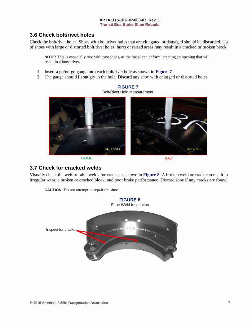
3.6 Check bolt/rivet holes
Check the bolt/rivet holes. Shoes with bolt/rivet holes that are elongated or damaged should be discarded. Use
of shoes with large or distorted bolt/rivet holes, burrs or raised areas may result in a cracked or broken block.
NOTE: This is especially true with cast shoes, as the metal can deform, creating an opening that will
result in a loose rivet.
1. Insert a go/no-go gauge into each bolt/rivet hole as shown in Figure 7.
2. The gauge should fit snugly in the hole. Discard any shoe with enlarged or distorted holes.
FIGURE 7 Bolt/Rivet Hole Measurement
GOOD BAD
3.7 Check for cracked welds
Visually check the web-to-table welds for cracks, as shown in Figure 8. A broken weld or crack can result in
irregular wear, a broken or cracked block, and poor brake performance. Discard shoe if any cracks are found.
CAUTION: Do not attempt to repair the shoe.
FIGURE 8 Shoe Weld Inspection
Inspect for cracks

APTA BTS-BC-RP-003-07, Rev. 1 Transit Bus Brake Shoe Rebuild
© 2016 American Public Transportation Association 8
3.8 Check roller seat
Check roller seat (see Figure 9) for the following:
1. Wear
2. Out-of-roundness
3. Flared condition
FIGURE 9 Roller Seat
Worn roller seats can cause uneven braking and damage to S-cams.
3.9 Check return spring pin
Inspect the brake shoe for return spring pin wear, damage or looseness. If the pin is missing or loose, then
check holes with a new pin. Discard the shoe if the new pin is loose. If serviceable, follow the replacement
procedure in Section 6.
IMPORTANT: Wedge-style and Q Plus brake shoe pins are designed to be loose.
3.10 Inspect cast iron shoes
Cast iron shoes can and will exhibit wear and damage that will result in the shoes being rejected for rebuild.
Like pressed steel shoes, the standard criteria, such as stretch, spring pin and roller pocket wear, should be
inspected. Additional items that are exhibited in cast shoes are as follows (see Figure 10).
3.10.1 Broken casting
Check for cracks and obvious broken casting.
3.10.2 Rust jacking
Rust jacking or excessive rust will result in table wear and distortion of the rivet holes. The table surface of
the shoe should be flat, and the rivet holes must be round with no elongation.
3.10.3 Roller pocket wear
Excessive pocket wear will cause a % reduction in the drum to shoe contact. A difference from the top to
bottom shoe on pocket wear will cause uneven torque load on the shoe and uneven wear of the brake.

APTA BTS-BC-RP-003-07, Rev. 1 Transit Bus Brake Shoe Rebuild
© 2016 American Public Transportation Association 9
FIGURE 10 Shoe Inspection – Damage
Rust jacking Broken casting Roller pocket wear
4. Anchor pin bushing replacement Replace the anchor pin bushings at each rebuild. Bushing wear increases the spacing between the shoe and the
anchor pin. This may affect cam rotation and brake chamber push rod stroke. Worn bushings can cause
uneven braking and prevent automatic brake adjusters from maintaining proper push rod travel.
FIGURE 11 Brushing Removal/Installation Tool
Insert a new bushing on the removal/installation tool, as shown in Figure 11. Using the proper bushing driver,
drive out the old bushing while concurrently inserting the new bushing. It is important to support the web of
the brake shoe when installing bushing. Failure to support the web may result in bent, damaged or broken
webs. Verify sliding fit of the anchor pin, and ream if necessary.
5. Corrosion inhibitor treatment of brake shoes After cleaning and inspecting the brake shoe, apply the corrosion inhibitor prior to installation of the brake
block.

APTA BTS-BC-RP-003-07, Rev. 1 Transit Bus Brake Shoe Rebuild
© 2016 American Public Transportation Association 10
Minimum specifications for corrosion inhibitor include the following:
ASTM B117 salt spray test for 96 hours. (It is recommended that properties with operating conditions
that are conducive to severe corrosion should consider using a product that passes a 168-hour salt
spray test.)
ASTM D3359 crosshatch adhesion test.
CAUTION: To avoid getting corrosion inhibitor on the working surface of the bushings, mask the
bushing with tape or a thin layer of grease, or install the bushing after the corrosion inhibitor process.
6. Install return spring pin Use a brass hammer to install the brake return spring pin. Do not damage the pin or the shoe. See Figure 12.
FIGURE 12 Installation of Brake Shoe Return Spring Pin
7. Brake block installation Inspect the brake block by visually checking it for cracks, chipped edges and corners, as shown in Figure 13.
The surface that mounts on the brake shoe table should be clean and free of loose material. Brake blocks that
show any sign of damage or imperfection should not be used.
FIGURE 13 Brake Block Inspection

APTA BTS-BC-RP-003-07, Rev. 1 Transit Bus Brake Shoe Rebuild
© 2016 American Public Transportation Association 11
7.1 Combination brake block installation
There are multiple methods of installing combination blocks. Refer to the manufacturer’s instructions for your
application.
7.2 Brake block fastening procedure
Block and fastening hardware must be compatible.
7.2.1 Installing riveted brake block
Cracks in the rivet curl can be avoided by doing the following:
Inspecting and maintaining the rivet setting equipment and tools
Utilizing brass-plated steel rivets with a wax coating
Inspecting the concentricity of rivet hole to shank
Utilizing riveting equipment that compensates for variations in rivets, counter-bores and table
thickness
7.3 Rivet lengths
Rivet lengths are measured from the underside of the head to the end of the shank. See Figure 14 for an
example of a rivet length calculation.
FIGURE 14 Rivet Length Calculation
Combined material thickness .500 Clinch allowance (¼ in.) +.162 Rivet length .662 = 11/16 in. long
European brake shoes utilize metric rivets. The OEM brake shoes utilize an 8 mm hollow rivet (see
Figure 15).
APTA BTS-BC-RP-003-07, Rev. 1 Transit Bus Brake Shoe Rebuild
© 2016 American Public Transportation Association 12
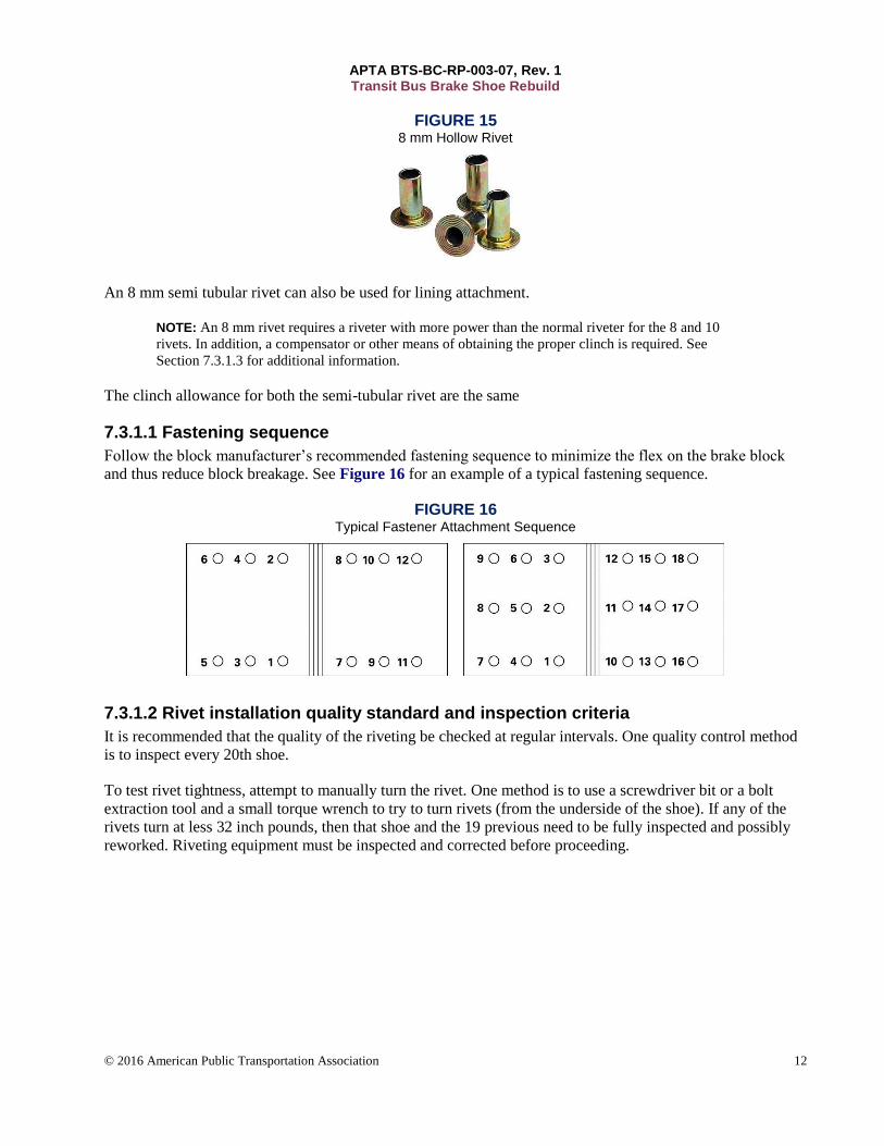
FIGURE 15 8 mm Hollow Rivet
An 8 mm semi tubular rivet can also be used for lining attachment.
NOTE: An 8 mm rivet requires a riveter with more power than the normal riveter for the 8 and 10
rivets. In addition, a compensator or other means of obtaining the proper clinch is required. See
Section 7.3.1.3 for additional information.
The clinch allowance for both the semi-tubular rivet are the same
7.3.1.1 Fastening sequence
Follow the block manufacturer’s recommended fastening sequence to minimize the flex on the brake block
and thus reduce block breakage. See Figure 16 for an example of a typical fastening sequence.
FIGURE 16 Typical Fastener Attachment Sequence
7.3.1.2 Rivet installation quality standard and inspection criteria
It is recommended that the quality of the riveting be checked at regular intervals. One quality control method
is to inspect every 20th shoe.
To test rivet tightness, attempt to manually turn the rivet. One method is to use a screwdriver bit or a bolt
extraction tool and a small torque wrench to try to turn rivets (from the underside of the shoe). If any of the
rivets turn at less 32 inch pounds, then that shoe and the 19 previous need to be fully inspected and possibly
reworked. Riveting equipment must be inspected and corrected before proceeding.

APTA BTS-BC-RP-003-07, Rev. 1 Transit Bus Brake Shoe Rebuild
© 2016 American Public Transportation Association 13
FIGURE 17 Ideal Rivet Installation Condition
A single hairline radial crack, provided it does not extend into the solid or “hole” portion of the rivet shank, is
acceptable.
Any of the following are unacceptable (see Figure 18):
Non-radial cracks
“Slice of pie” cracks
Cracks that extends into the solid or “hole” portion of the rivet shank
FIGURE 18 Unacceptable Rivet Conditions
“Slice of pie” cracks or cracks that extend into the solid or “hole” portion of the rivet shank
Multiple hairline cracks Variation in the table thickness and countersink of cast shoes
Most North American brake blocks designed for riveted installation have 150-degree counterbore. European
blocks may have 180-degree counterbore. Most North American brake blocks designed for bolted installation
have either an 82-degree counterbore and a ⅜-in. bolt or 150-degree counterbore and a ¼-in. bolt. When using
a different fastener, be sure to use the appropriate counterbore angle.

APTA BTS-BC-RP-003-07, Rev. 1 Transit Bus Brake Shoe Rebuild
© 2016 American Public Transportation Association 14
A variation in the table thickness and/or the countersink can result in improper rivet clinch. A riveter
compensates for this variation.
7.3.1.3 Compensator
Compensators (Figure 19) enable riveting machines to accommodate varying work thicknesses. Anvil arm
compensators allow the anvil to move vertically as the rivet is driven down through the work, supporting the
anvil with spring or air pressure. Top-pin compensators work in a similar fashion, except that they use a
spring-loaded top pivot pin. With either model, pressure can be adjusted so that each rivet is set with the same
amount of pressure regardless of part thickness.
FIGURE 19 Compensator
7.3.1.4 Flywheel riveter
A flywheel riveter (Figure 20) applies pressure to the rivet and works on the setup of the machine to the
standard thickness of the brake shoe table. The standard flywheel riveter does not compensate for a variation
in the thickness. A spring compensator can be added to some machines to allow for the proper clinching of
the rivet.
FIGURE 20 Flywheel Riveter
7.3.1.5 Hydraulic riveter
Like pneumatic riveters, a hydraulic riveter (Figure 21) can automatically compensate for minor variances in
the parts being fastened. Variances could include work thickness, part orientation or rivet length.

APTA BTS-BC-RP-003-07, Rev. 1 Transit Bus Brake Shoe Rebuild
© 2016 American Public Transportation Association 15
FIGURE 21 Hydraulic Riveter
7.3.1.6 Hybrid air/oil riveter
The hybrid air/oil riveter is less expensive and has a higher operation speed than the hydraulic riveter. It
compensates for variations in part thickness or rivet length to ensure tight settings without crushing the part.
7.3.2 Installing bolted blocks
Refer to manufacturers’ instructions for alternate installation
7.3.2.1 Specifications for brake bolts (SAE J663)
The standard bolt for bolted blocks is brass or plated steel, slotted, flathead screw. The dimension, thread size
and angle of the countersink are dependent on the style of brake. Refer to Table 5 in Appendix B for the bolt
dimensions.
Refer to SAE Specification J478 or ANSI Specifications 18.6.1, 18.6.2, 18.6.3 and 18.6.4 for additional
details of dimensional specifications.
7.3.2.2 Specifications for lock washers
Use a hardened carbon steel helical spring lock washer. Refer to Table 6 in Appendix B.
Refer to SAE Specification J489B for additional details of dimensional specifications.
7.3.2.3 Specifications for nuts
Use zinc-coated or brass nuts with the appropriate dimensions and thread size, as noted in Table 7 of
Appendix B.
7.3.2.4 Fastening sequence
Install all the bolts through the block and the shoe table. Install the lock washers and nuts. Tighten all
fasteners finger tight. See Figure 22.

APTA BTS-BC-RP-003-07, Rev. 1 Transit Bus Brake Shoe Rebuild
© 2016 American Public Transportation Association 16
FIGURE 22 Block Fastener Installation
Follow block manufacturer’s recommended torque pattern sequence to minimize the flex of the brake block
and to reduce block breakage. Using a torque wrench, tighten ¼-in. fasteners to 80–100 in.-lb, ⅜-in. fasteners
to 18–23 ft-lb, and 10 mm fasteners to 22 ft-lb (see Table 3).
NOTE: Refer to Figure 16 for an example of proper torque sequence.
TABLE 3 Brake Torque
Size Fastener Torque (ft-lb) Fastener Torque (in.-lb)
¼ in. × 28 UNF 7–8 80–100
5/16 (8 mm) 11–12 133–144
⅜ × 24 UNF 13–15 156–180
⅜ × 24 UNC 18–23 216–240
7.3.3 Bonded blocks
Attaching bonded block is a specialized process that should be performed only by a qualified vendor.
8. Final assembly Lubricate and install roller at time of brake shoe installation to prevent contamination (Figure 23).
CAUTION: Take care not to get any grease on the surface of the roller that contacts the S-cam.
APTA BTS-BC-RP-003-07, Rev. 1 Transit Bus Brake Shoe Rebuild
© 2016 American Public Transportation Association 17
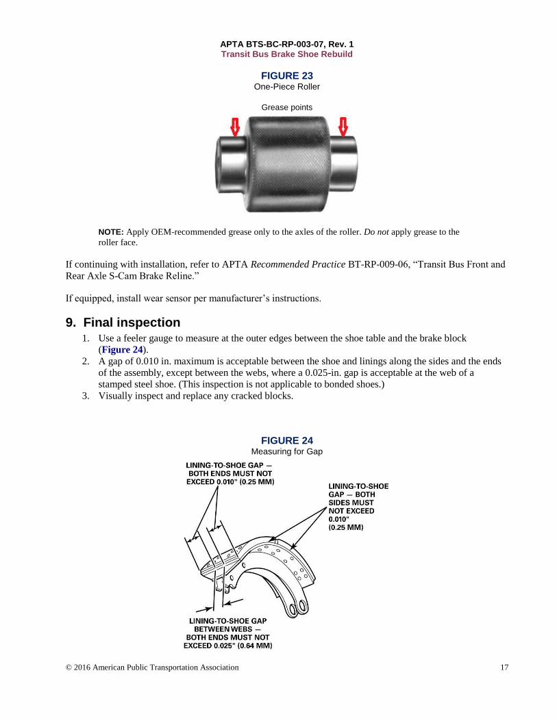
FIGURE 23 One-Piece Roller
Grease points
NOTE: Apply OEM-recommended grease only to the axles of the roller. Do not apply grease to the
roller face.
If continuing with installation, refer to APTA Recommended Practice BT-RP-009-06, “Transit Bus Front and
Rear Axle S-Cam Brake Reline.”
If equipped, install wear sensor per manufacturer’s instructions.
9. Final inspection 1. Use a feeler gauge to measure at the outer edges between the shoe table and the brake block
(Figure 24).
2. A gap of 0.010 in. maximum is acceptable between the shoe and linings along the sides and the ends
of the assembly, except between the webs, where a 0.025-in. gap is acceptable at the web of a
stamped steel shoe. (This inspection is not applicable to bonded shoes.)
3. Visually inspect and replace any cracked blocks.
FIGURE 24 Measuring for Gap

APTA BTS-BC-RP-003-07, Rev. 1 Transit Bus Brake Shoe Rebuild
© 2016 American Public Transportation Association 18
10. Documentation Brake shoe rebuild and inspection should be documented on a standard form (electronic or paper) and be
reviewed and filed in accordance with operating agency procedures. See Appendix A for an example.
APTA BTS-BC-RP-003-07, Rev. 1 Transit Bus Brake Shoe Rebuild
© 2016 American Public Transportation Association 19
Related APTA standards
APTA RP-xxx-00x-16, Rev. xx, “Name name name name” [Body Text with Body bold style applied to
number, hanging indent of .25 inches]
APTA RP-xxx-00x-16, Rev. xx, “Name name name name”
References
American National Standards Institute (ANSI), Standards 18.6.1 18.6.2, 18.6.3 and 18.6.4.
www.ansi.org/default.aspx#.UVMoohdwq6U
ASTM International, ASTM B117, “Standard Practice for Operating Salt Spray (Fog) Apparatus.”
www.astm.org/Standards/B117.htm
ASTM International, ASTM D3359, “Standard Test Methods for Measuring Adhesion by Tape Test.”
www.astm.org/Standards/D3359.htm
Society of Automotive Engineers, SAE J478, “Slotted and Recessed Head Screws.”
http://sae.nufu.eu/std/J478
This standard shall also be used in conjunction with the most recent edition of the following publications:
OEM manuals
OSHA regulations
Brake manufacturer service manuals (example: Meritor Maintenance Manual 23B Bus and Coach
Cam Brakes)
Technology and Maintenance Council of the American Trucking Association Recommended
Practices
Definitions
original equipment manufacturer (OEM): The vehicle manufacturer.
brake block: For the purposes of this document, all friction material and/or brake lining will be referred to as
brake block.
combination brake blocks: Brake blocks with more than one formulation identification for each wheel.
Abbreviations and acronyms
ASTM formerly the American Society for Testing and Materials
DOT Department of Transportation
FMCSA Federal Motor Carrier Safety Administration
FMVSS Federal Motor Vehicle Safety Standard
HEPA High-Efficiency Particulate Air
MSDS material safety data sheets
MSHA Mine Safety and Health Administration
NIOSH National Institute for Occupational Safety and Health
OEM Original Equipment Manufacturer
OSHA Occupational Health and Safety Administration
SAE Society of Automotive Engineers
APTA BTS-BC-RP-003-07, Rev. 1 Transit Bus Brake Shoe Rebuild
© 2016 American Public Transportation Association 20
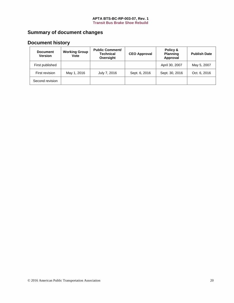
Summary of document changes
Document history
Document Version
Working Group Vote
Public Comment/ Technical Oversight
CEO Approval Policy & Planning Approval
Publish Date
First published April 30, 2007 May 5, 2007
First revision May 1, 2016 July 7, 2016 Sept. 6, 2016 Sept. 30, 2016 Oct. 6, 2016
Second revision

APTA BTS-BC-RP-003-07, Rev. 1 Transit Bus Brake Shoe Rebuild
© 2016 American Public Transportation Association 21
Appendix A: Quality control sample form
Brake shoe inspection repair and block replacement
Batch No: Part No.
Description:
Inspection Rejected Quantity
Stretch
Table flatness
Web distortion
Table arch
Bolt holes
Table thickness
Welds
Roller seats
Anchor pin holes
Broken casting
Quantity of shoes inspected Quantity of shoes rejected
Inspected by
Maintenance
Material control

APTA BTS-BC-RP-003-07, Rev. 1 Transit Bus Brake Shoe Rebuild
© 2016 American Public Transportation Association 22
Appendix B: Rivets and bolts for brake blocks (SAE J663B)
Brass tubular rivets for brake blocks
Table 4 gives dimensions for brass tubular rivets used for brake blocks.
NOTE: For drill and countersink dimensions for rivet and bolt holes, see SAE J660.
TABLE 4 Typical Dimensions for Common Brake Block Semi-Tubular SAE Rivets
Rivet Number #10 #20 ⅜ 8 mm (full table)
Rivet Shank Diameter, nominal 0.250 in. 0.200 in. 0.375 in. .307 in (7.8 mm)
Clinch allowance 0.162 in. 0.162 in. 0.218 in. 4.5 mm minimum
Diameter of hole in shoe 17/64 in. 14/64 in. 25/64 in. 8.2 mm
Rivet Length in increments of 1/16 in. 1/16 in. 1/16 in. 2 mm
Rivet Length 10/16 10/16 1 in. 18-20 mm
Bolts for brake blocks
The standard bolt for bolted blocks is brass or brass-plated, slotted, flathead screw. The dimension, thread size
and angle of the countersink are dependent on the style of brake. Refer to Table 5 and Figure 25 for the bolt
dimensions.
TABLE 5 Brake Bolt Specifications (SAE J663, July 2001)
Brake Type
Size Threads per Inch
Body Diameter
Depth of Head
Width of Slot Depth of Slot Material Torque
Max Max Min Max Min
W-series
⅜ in. ⅜-16
UNC-2A 0.375 0.219 0.094 0.081 0.106 0.070
EJ461 (brass)
18-23 ft-lb
Cast plus
¼ in. ¼-28
UNF-2A 0.25 0.108 0.061 0.031 0.0385 0.0235
UNSM C27000 (brass)
7-8 ft-lb
MAN
5/16-18 × 1 in. Slotted 180 Degree
Countersink Full Shoulder
18 5/16 X .075 .005 ,073 + -005 Brass 10-11 ft lb

APTA BTS-BC-RP-003-07, Rev. 1 Transit Bus Brake Shoe Rebuild
© 2016 American Public Transportation Association 23
FIGURE 25 Xxx Xxxx Xxxxx
W-type brake bolt Cast Plus brake bolt Hollow rivet
TABLE 6 Lock Washer Specifications
Brake Type Nominal Size Inside Diameter Outside
Diameter
Section Width Material Process
Max Min Min
W-series ⅜ in. 0.375 0.375 0.219 0.68 0.141 SAE 1055-1056 38–46 HRC
Cast Plus ¼ in. 0.250 0.25 0.108 0.487 0.109 SAE 1055-1056 38–46 HRC
TABLE 7 Zinc Coated and Brass Nut Specifications
Brake Type Nominal Size Thread Thickness Flat Width Corner Width
Material Max Min Max Min Max Min
W-series ⅜ in. 0.375 ⅜-16 UNC-2B 0.337 0.320 0.562 0.551 0.650 0.628 38–46 HRC
Cast Plus ¼ in. 0.250 ¼-28 UNF-2B 0.226 0.212 0.438 0.428 0.505 0.488 38–46 HRC