transition in gas turbine control system architecture ... · pdf filedennis culley glenn...
TRANSCRIPT
Dennis CulleyGlenn Research Center, Cleveland, Ohio
Transition in Gas Turbine Control SystemArchitecture: Modular, Distributed, andEmbedded
NASA/TM—2010-216806
September 2010
GT2010–23226
https://ntrs.nasa.gov/search.jsp?R=20100036217 2018-05-21T01:37:40+00:00Z

NASA STI Program . . . in Profi le
Since its founding, NASA has been dedicated to the advancement of aeronautics and space science. The NASA Scientifi c and Technical Information (STI) program plays a key part in helping NASA maintain this important role.
The NASA STI Program operates under the auspices of the Agency Chief Information Offi cer. It collects, organizes, provides for archiving, and disseminates NASA’s STI. The NASA STI program provides access to the NASA Aeronautics and Space Database and its public interface, the NASA Technical Reports Server, thus providing one of the largest collections of aeronautical and space science STI in the world. Results are published in both non-NASA channels and by NASA in the NASA STI Report Series, which includes the following report types: • TECHNICAL PUBLICATION. Reports of
completed research or a major signifi cant phase of research that present the results of NASA programs and include extensive data or theoretical analysis. Includes compilations of signifi cant scientifi c and technical data and information deemed to be of continuing reference value. NASA counterpart of peer-reviewed formal professional papers but has less stringent limitations on manuscript length and extent of graphic presentations.
• TECHNICAL MEMORANDUM. Scientifi c
and technical fi ndings that are preliminary or of specialized interest, e.g., quick release reports, working papers, and bibliographies that contain minimal annotation. Does not contain extensive analysis.
• CONTRACTOR REPORT. Scientifi c and
technical fi ndings by NASA-sponsored contractors and grantees.
• CONFERENCE PUBLICATION. Collected papers from scientifi c and technical conferences, symposia, seminars, or other meetings sponsored or cosponsored by NASA.
• SPECIAL PUBLICATION. Scientifi c,
technical, or historical information from NASA programs, projects, and missions, often concerned with subjects having substantial public interest.
• TECHNICAL TRANSLATION. English-
language translations of foreign scientifi c and technical material pertinent to NASA’s mission.
Specialized services also include creating custom thesauri, building customized databases, organizing and publishing research results.
For more information about the NASA STI program, see the following:
• Access the NASA STI program home page at http://www.sti.nasa.gov
• E-mail your question via the Internet to help@
sti.nasa.gov • Fax your question to the NASA STI Help Desk
at 443–757–5803 • Telephone the NASA STI Help Desk at 443–757–5802 • Write to:
NASA Center for AeroSpace Information (CASI) 7115 Standard Drive Hanover, MD 21076–1320
Dennis CulleyGlenn Research Center, Cleveland, Ohio
Transition in Gas Turbine Control SystemArchitecture: Modular, Distributed, andEmbedded
NASA/TM—2010-216806
September 2010
GT2010–23226
National Aeronautics andSpace Administration
Glenn Research CenterCleveland, Ohio 44135
Prepared for theTurbo Expo 2010sponsored by the American Society of Mechanical Engineers (ASME)Glasgow, Scotland, United Kingdom, June 14–18, 2010

Acknowledgments
This work is supported by the NASA Fundamental Aeronautics program, Subsonic Fixed Wing project. The author also wishes to acknowledge the important contributions of the Distributed Engine Control Working Group (DECWG), a consortium of
government and industry representatives working with turbine engine control systems.
Available from
NASA Center for Aerospace Information7115 Standard DriveHanover, MD 21076–1320
National Technical Information Service5301 Shawnee Road
Alexandria, VA 22312
Available electronically at http://gltrs.grc.nasa.gov
This work was sponsored by the Fundamental Aeronautics Program at the NASA Glenn Research Center.
Level of Review: This material has been technically reviewed by technical management.

NASA/TM—2010-216806 1
Transition in Gas Turbine Control System Architecture: Modular, Distributed, and Embedded
Dennis Culley
National Aeronautics and Space Administration Glenn Research Center Cleveland, Ohio 44135
Abstract
Controls systems are an increasingly important component of turbine-engine system technology. However, as engines become more capable, the control system itself becomes ever more constrained by the inherent environmental conditions of the engine; a relationship forced by the continued reliance on commercial electronics technology. A revolutionary change in the architecture of turbine-engine control systems will change this paradigm and result in fully distributed engine control systems. Initially, the revolution will begin with the physical decoupling of the control law processor from the hostile engine environment using a digital communications network and engine-mounted high temperature electronics requiring little or no thermal control. The vision for the evolution of distributed control capability from this initial implementation to fully distributed and embedded control is described in a roadmap and implementation plan. The development of this plan is the result of discussions with government and industry stakeholders.
Nomenclature
CLP Control Law Processor DECWG Distributed Engine Control Working Group ECU Engine Control Unit FADEC Full Authority Digital Engine Control I/O Input/Output, specifically conversion between
analog and digital domains ITAR International Traffic in Arms Regulations
Introduction
There have been at least two revolutionary changes to the architecture of turbine-engine control systems since the invention of the jet engine. The first was the application of electronics (Ref. 1) to supplement, and eventually replace, the intricate hydro-mechanical controls then in standard use. While hydro-mechanical controls were certainly capable of providing acceptable control functionality, their size, weight, and expense constrained the ability to expand the number of control variables, which is a measure of control system complexity. The compactness and flexibility of this early electronics technology enabled the increase in complexity even though the initial capability and reliability (Refs. 2 to 5) of the primitive electronics were lacking by today’s standards.
Early in this period, electronics were limited to supervisory or trim functions. Over time, many of the initial deficiencies were rectified and electronics provided innovations (Refs. 6 and 7) which far surpassed the capability of hydro-mechanical control. Eventually, electronic systems would advance to the point that they were capable of performing as “full authority” meaning they could control the entire operation of an engine from start-up to shutdown according to the pilot’s throttle command.
The second revolutionary change to control architecture occurred when full authority control was implemented with digital electronics and software, known as a full authority digital engine control (FADEC) (Refs. 8 to 20). This change is not significant because of the transition from analog to digital electronics, but because it represents a change in control law implementation from the physical domain of hardware to the virtual domain of software. The unlimited flexibility of software provided an unsurpassed capability for quickly implementing system improvements without the need to make hardware modifications. Whereas analog electronic control was a representation of individual, localized hydro-mechanical control functions, software-driven control architecture consolidated all of the engine control laws in one physically central location from which it could be easily modified. Consequently, the control laws themselves have became much more aware of the system state, limited mainly by the available computational power (Ref. 21). This centralized control hardware architecture, circa 1985, remains the state-of-the-art for present-day turbine propulsion systems.
Early hydro-mechanical controls were, in effect, distributed control systems. Ironically, the next revolutionary change in control architecture will replicate this physical distribution of control functionality; however, it will also preserve the unifying centrality of FADEC architecture. This will be achieved through a networked system of embedded electronic controls. Not surprisingly, these changes are being driven by familiar constraints such as weight, volume, and cost as well as new concerns about the expanding complexity of engine and integrated vehicle control.
There is a dichotomy of the driving forces behind revolutionary change in turbine engine control architecture that is representative of the need to reconcile present and future risks. That is, those involved with the future of present production systems are prone to be more cost-driven in their goals while those concerned with as-yet-to-be-designed systems tend to be more capability-driven. In actuality, the
NASA/TM—2010-216806 2
forces for cost-control and capability need to be reconciled for the revolutionary change in control architecture to occur.
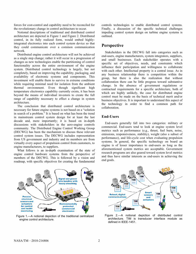
Notional descriptions of traditional and distributed control architecture are depicted in Figure 1 and Figure 2. Distributed control, in its fully realized form, would embed highly-integrated electronics into each control system device so that they could communicate over a common communication network.
Distributed engine control architecture will not be achieved as a single step change; rather it will occur in a progression of changes as new technologies enable the partitioning of control functionality across the entire environment of the engine system. Distributed control technology is largely, but not completely, based on improving the capability, packaging, and availability of electronic systems and components. This investment will enable them to survive in extreme conditions while requiring minimal need for isolation from the ambient thermal environment. Even though significant high temperature electronics capability currently exists, it has been beyond the means of individual investors to create the full range of capability necessary to effect a change in system architecture.
The conclusion that distributed control architecture is necessary for future engine systems is not based on a “solution in search of a problem.” It is based on what has been the trend in mainstream control system design for at least the last decade and, more importantly; it is based on in-depth discussions with stakeholders in the aero-engine controls community. The Distributed Engine Control Working Group (DECWG) has been the mechanism to discuss these relevant control system issues. The DECWG includes representation from US government and industry and its members are from virtually every aspect of propulsion control from customers, to engine manufacturers, to suppliers.
What follows is an in-depth examination of the state of engine control hardware systems from the perspective of members of the DECWG. This is followed by a vision and roadmap, with specific objectives for creating the fundamental
controls technologies to enable distributed control systems. Finally, a discussion of the specific technical challenges impeding control system design on turbine engine systems is outlined.
Perspective
Stakeholders in the DECWG fall into categories such as end-users, engine manufacturers, system integrators, suppliers, and small businesses. Each stakeholder operates with a specific set of objectives, needs, and constraints which influence their participation and willingness to collaborate with each other. Intellectual property is a central issue. As in any business relationship there is competition within the group, but there is also the realization that without collaboration there can be little progress toward substantive change. In the absence of government regulations or contractual requirements for a specific architecture, both of which are highly unlikely, the case for distributed engine control must be made on the basis of technical merit and/or business objectives. It is important to understand this aspect of the technology in order to find a common path for collaboration.
End-Users
End-users generally fall into two categories: military or commercial. End-users tend to look at engine system level metrics such as performance (e.g., thrust, fuel burn, noise, emissions, responsiveness, stability), weight (also a subset of performance), and life-cycle cost when evaluating propulsion systems. In general, the specific technology on board an engine is of lesser importance to end-users as long as the aforementioned system metrics are acceptable. Government research programs are also geared toward system level metrics and thus have similar interests as end-users in achieving the end goals.
Figure 1.—A notional depiction of the traditional centralized
engine control architecture.
Figure 2.—A notional depiction of distributed control
architecture. TIM is transducer interface module as defined in IEEE-1451.

NASA/TM—2010-216806 3
End-user life-cycle costs include acquisition, operating and maintenance costs. Operating costs are largely related to fuel burn while maintenance costs include those related to keeping a system in a state of availability. Since fuel is by far the greatest cost for an engine system over its life cycle there is intense interest in technologies that reduce fuel burn. System availability is important to the end-user because it affects mission success for military users and profitability for commercial users. System availability is directly related to component reliability and the capability to quickly diagnose and repair problems when they occur. Demonstrating how control system architecture impacts these metrics for end-users is critical to gaining their support and generating pull for new controls technology.
Acquisition costs increase as technology is added to a system, at least initially. Customers accept new technology when they receive a demonstrable benefit but they resist buying more capability than they need. In lieu of customer pull, regulatory measures are, in general, the only other method of integrating new technology in engine systems.
Military users and government research programs have an interest in the development of distributed control because they often have a longer term view of engine systems and their future limitations. Even so, these efforts have always focused on targeted applications and have achieved limited success in advancing the technology to production systems. The fundamental roadblock is the initial cost of developing the appropriate high temperature electronics. No one, including customers, end-users, government programs, industries or business has been willing or able to provide the investment necessary to resolve the remaining technical challenges and make available affordable electronic components for creating viable distributed architectures. From their perspective, the narrowly defined need has not been imminent enough to justify the expense of this technology.
However, that is beginning to change. New engine control technologies for combustion, compressor stability, and flow control tend to be high-bandwidth, computation-intensive technologies that will drive the control law processing
requirements of future engine control systems. Additionally, engine diagnostics and prognostics, and adaptive control technologies are expected to place an increasing burden on the centralized Engine Control Unit (ECU) hardware. A commensurate investment to ensure control architecture does not become the limiting factor in engine systems is warranted.
Engine Manufacturers
There is tremendous variability in the different types of engine systems in response to the needs of customers. Customers do not buy technology, they buy capability, and their time frame of reference is often very short in contrast to the life expectancy of the engine which can be 20 years or more. This puts pressure on manufacturers to develop technology to solve immediate problems that have short term payoff. This type of technology is incremental or evolutionary in nature, not revolutionary. Still, the accumulation of incremental changes in the engine system over time leads to the development of system constraints which eventually require higher risk approaches to overcome them.
Over time and with many contributing technologies, engine system cores have become smaller and lighter for a given thrust value while operating at significantly hotter temperatures. For military systems, this translates into significant challenges for mounting control electronics on the hot engine core as shown in Figure 3. Commercial engines, which traditionally mount electronics on the cold fan casing shown in Figure 4, are also affected. The drive toward higher bypass engines, with either shrouded or open fans, is pushing electronic assemblies off the fan casing. The choice becomes mounting electronics on the hot core, akin to military engines, or at greater distances from the engine control elements. Both choices increase system weight from either additional cooling apparatus or longer cable harnesses.
Engine systems are developed for a wide variety of applications and the design of each control system is peculiar to that engine, creating a tremendous cost and schedule driver
Figure 3.—Engine core mounted electronics require cooling
which increases system weight and complexity.
Figure 4.—Engine fan casing mounted electronics are in a
cool environment.

NASA/TM—2010-216806 4
for manufacturers. While there is a great deal of similarity in the function and use of these control system components, there is very little reuse or commonality in the control hardware. This is primarily because emphasis is placed on meeting customer requirements and each design is highly optimized for that solution.
Engine systems are typically long-lived items and will be modified or upgraded over their life span. The reason can be due to performance upgrades requested by the customer, but are often unscheduled due to common maintenance coupled with electronic component obsolescence. In either case, the result is a lengthy redesign and requalification process to satisfy certification authorities.
Electronic component obsolescence is a complete wildcard in the design of engine control systems. Virtually the same electronic parts found in consumer applications are used in engine controls. The constant improvement in commercial electronics due to consumer demand drives components out of production after only a few years. However, these control system parts are needed to support an engine system lifespan of two decades or more. Lifetime buys of an electronic part are often the only recourse.
All of these issues are incorporated in the research, development, test, and evaluation costs incurred by the manufacturer and are absorbed by the customer as part of the acquisition cost of the engine or upgrade. While the manufacturer can pass these costs along, they are not trivial and tend to delay (Ref. 22) the customer’s decision to purchase new systems or upgrades.
Engine manufacturers are interested in distributed control technology for several reasons. It is becoming apparent that controls could become a limiting factor in future systems and manufacturers are beginning to recognize that it will affect their competitiveness. But there has always been interest in this technology for its potential to decrease the entire engine design cycle time and reduce the substantial non-recurring engineering costs associated with any new design or modification. Manufacturers also recognize the opportunity for additional customer value in terms of improved reliability and fault detection and system weight reduction. Regardless, the expense of developing the technology and the lack of customer pull to cover the costs has placed the technology beyond the reach of any individual engine manufacturer.
System Integrators
Manufacturers work closely with a system integrator to implement the engine control. However, the definition of the control system often begins after the preliminary design of the engine is complete. This limits the options available to the system integrator and also puts disproportional pressure on the need to reduce control system cost and weight. As mentioned above, innovation is generally reserved for resolving the near term issues under the constraints of the existing mechanical system. Most of this innovation goes into increasing the density of packaging in the ECU while the addition of new
control functions is often determined by the impact to weight and cost.
The ECU is the center of the control system as it interfaces with virtually every electrical device on the engine and communicates with the airframe control as well. It also receives electrical power feeds from the engine and/or airframe and provides the specific conditioned power needs of every device in the control system. Due to the centrality of the ECU it is very sensitive to changes anywhere in the engine control system.
Across engine platforms, there is a great deal of similarity in control element functions; measurements such as temperature, pressure, speed, flow, and position; and actuation such as fuel metering, bleeds and variable stator geometry. Yet few of these common control element functions result in shared components between engine models. Instead, they are uniquely defined at the hardware level for each engine system.
The ECU assembly contains these unique and redundant interfaces for all of the control input/output (I/O). This drives the complexity of the circuitry within the ECU, especially the analog circuits which must accommodate each unique control element. The complexities of the internal details of these interfaces would be completely masked by the environmental enclosure if it were not for the multiple, high pin count connectors on the outside walls. The number and size of these connectors often dictate the dimensions of the enclosure.
Any change to the control design, whether initial design iterations or a field upgrade requires a complex synchronization of the supply chain, the hardware documentation, and the configuration management system. One change can affect several components. Within the ECU, circuit boards could be modified. Depending on the extent of the modifications this could ripple through to require a redesign of the power supply, package connectors, and even the mechanical design of the enclosure. The latter must be checked against the available mounting envelope on the engine. In addition, the system as a whole has to be qualified for flight worthiness which requires a substantial investment in capital and time. As a result, engine control system modifications at any point in the life cycle can cost as much as the original design.
System integrators are interested in distributed control for the obvious impact it would have on the design cycle. If every control device implemented a common interface for communication and power it would greatly simplify integration. Changes in any one device would be firewalled by the common interface so that hardware modifications would be localized to that device. This would largely mitigate the electronic obsolescence issue. Requalification of the system could be achieved with rigorous requalification of a single control system component and adherence to the interface standard.
With many of the complex hardware integration issues resolved by distributed control, integrators could focus more resources on value-added items such as system health monitoring and adaptive control.

NASA/TM—2010-216806 5
Suppliers
Suppliers provide the components of the engine control system. Devices such as pressure and temperature sensors, speed indicators, solenoids, motors, and electrically operated hydraulic actuators. Often these devices are complex assemblies such as fuel controls with integral sensors and actuators. These devices sometimes begin from a common design but are highly modified electrically and mechanically for each specific application. High reliability and low cost for the specified accuracy are the drivers. The non-recurring engineering cost for these components is high because of their uniqueness and the need to supply these components for the engine lifetime.
Suppliers are interested in distributed control technology because it provides additional opportunities for them to compete in what is close to a commodity market. In a distributed system, standard interfaces allow the supplier to leverage common designs which could meet the needs for a variety of engine systems. Electrical as well as mechanical interfaces could be standardized thereby reducing non-recurring engineering costs, simplifying the task of the system integrator, and providing resiliency to system changes.
Suppliers could also significantly increase innovation because of the use of distributed technology. Embedded electronics provide new functionality enabling suppliers to concentrate on value-added capabilities similar to what is described in the IEEE 1451 specification (Ref. 23). For instance, actuators could be equipped with embedded local loop closure to offload the control law processor (CLP) and improve responsiveness. Sensors could incorporate technology to maintain accuracy over time and/or under varying conditions while identifying those modes of operation to the CLP. Perhaps some of the most obvious value-added capabilities will be related to improved system reliability and fault detection, accomplished through the use of built-in test and in-situ interrogation of system components.
Schemes that are much more sophisticated could be implemented. For instance, high bandwidth data from a pressure or vibration sensor could be filtered through a signal processor to quickly detect a compressor stall signature without dumping large amounts of data over the network to the CLP. These same devices could sense the engine operating mode by monitoring network communication data and internally compensating its detection parameters based on engine speed or other conditions.
Lastly, many component upgrades or device variants could be accomplished just by modifying the embedded firmware.
Small Business
Small businesses find it difficult to break into established markets like turbine engine control because of the established competition. Manufacturers assume significant liability for the
product and therefore levy a requirement for high-reliability and low risk. Manufacturers vigorously protect intellectual property and have a need for a long term, dependable relationship which favors established suppliers.
Small businesses are interested in distributed control because the entry barriers are lowered for everyone. While the requirements for high reliability do not change, the risk is significantly reduced by the use of a standard interface specification. If the device does not prove to be adequate or the small business fails, there are other suppliers to fill the need in a short time frame. Intellectual property is protected for both parties since the function and embedded intelligence is firewalled through the standard interface.
The issues described in the Perspective section are largely associated with the processes, logistics, and business case for turbine-engine control systems. Certainly these are barriers to achieving successful distributed systems, especially when viewed from a narrow perspective. However, when viewed from a wider perspective, the performance advantage and value of distributed architecture for every stakeholder is readily apparent. Finding common ground for stakeholders to leverage each other’s investment will be the key to success. The vision and roadmap provides a template for that interaction.
Vision and Roadmap
The vision for implementing distributed engine control occurs as a progressive capability described in three milestone architectures beginning with the present day centralized architecture, shown in Figure 5. Successive capabilities are described as the Core I/O architecture, Networked Control architecture, and Fully Distributed architecture. Each step signifies a major milestone in hardware capability that is enabled by advancements in high temperature electronics. The significant features of each architecture are described in the subsequent sections.
Figure 5.—The centralized engine control architecture
typical of present day turbine engine systems.
NASA/TM—2010-216806 6
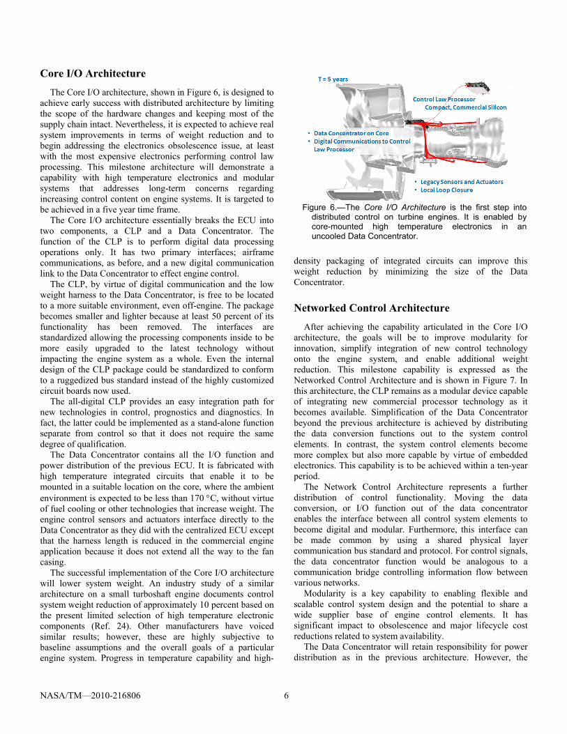
Core I/O Architecture
The Core I/O architecture, shown in Figure 6, is designed to achieve early success with distributed architecture by limiting the scope of the hardware changes and keeping most of the supply chain intact. Nevertheless, it is expected to achieve real system improvements in terms of weight reduction and to begin addressing the electronics obsolescence issue, at least with the most expensive electronics performing control law processing. This milestone architecture will demonstrate a capability with high temperature electronics and modular systems that addresses long-term concerns regarding increasing control content on engine systems. It is targeted to be achieved in a five year time frame.
The Core I/O architecture essentially breaks the ECU into two components, a CLP and a Data Concentrator. The function of the CLP is to perform digital data processing operations only. It has two primary interfaces; airframe communications, as before, and a new digital communication link to the Data Concentrator to effect engine control.
The CLP, by virtue of digital communication and the low weight harness to the Data Concentrator, is free to be located to a more suitable environment, even off-engine. The package becomes smaller and lighter because at least 50 percent of its functionality has been removed. The interfaces are standardized allowing the processing components inside to be more easily upgraded to the latest technology without impacting the engine system as a whole. Even the internal design of the CLP package could be standardized to conform to a ruggedized bus standard instead of the highly customized circuit boards now used.
The all-digital CLP provides an easy integration path for new technologies in control, prognostics and diagnostics. In fact, the latter could be implemented as a stand-alone function separate from control so that it does not require the same degree of qualification.
The Data Concentrator contains all the I/O function and power distribution of the previous ECU. It is fabricated with high temperature integrated circuits that enable it to be mounted in a suitable location on the core, where the ambient environment is expected to be less than 170 C, without virtue of fuel cooling or other technologies that increase weight. The engine control sensors and actuators interface directly to the Data Concentrator as they did with the centralized ECU except that the harness length is reduced in the commercial engine application because it does not extend all the way to the fan casing.
The successful implementation of the Core I/O architecture will lower system weight. An industry study of a similar architecture on a small turboshaft engine documents control system weight reduction of approximately 10 percent based on the present limited selection of high temperature electronic components (Ref. 24). Other manufacturers have voiced similar results; however, these are highly subjective to baseline assumptions and the overall goals of a particular engine system. Progress in temperature capability and high-
density packaging of integrated circuits can improve this weight reduction by minimizing the size of the Data Concentrator.
Networked Control Architecture
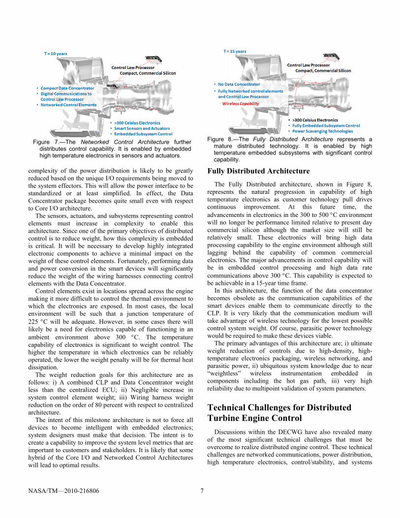
After achieving the capability articulated in the Core I/O architecture, the goals will be to improve modularity for innovation, simplify integration of new control technology onto the engine system, and enable additional weight reduction. This milestone capability is expressed as the Networked Control Architecture and is shown in Figure 7. In this architecture, the CLP remains as a modular device capable of integrating new commercial processor technology as it becomes available. Simplification of the Data Concentrator beyond the previous architecture is achieved by distributing the data conversion functions out to the system control elements. In contrast, the system control elements become more complex but also more capable by virtue of embedded electronics. This capability is to be achieved within a ten-year period.
The Network Control Architecture represents a further distribution of control functionality. Moving the data conversion, or I/O function out of the data concentrator enables the interface between all control system elements to become digital and modular. Furthermore, this interface can be made common by using a shared physical layer communication bus standard and protocol. For control signals, the data concentrator function would be analogous to a communication bridge controlling information flow between various networks.
Modularity is a key capability to enabling flexible and scalable control system design and the potential to share a wide supplier base of engine control elements. It has significant impact to obsolescence and major lifecycle cost reductions related to system availability.
The Data Concentrator will retain responsibility for power distribution as in the previous architecture. However, the
Figure 6.—The Core I/O Architecture is the first step into
distributed control on turbine engines. It is enabled by core-mounted high temperature electronics in an uncooled Data Concentrator.
NASA/TM—2010-216806 7
complexity of the power distribution is likely to be greatly reduced based on the unique I/O requirements being moved to the system effectors. This will allow the power interface to be standardized or at least simplified. In effect, the Data Concentrator package becomes quite small even with respect to Core I/O architecture.
The sensors, actuators, and subsystems representing control elements must increase in complexity to enable this architecture. Since one of the primary objectives of distributed control is to reduce weight, how this complexity is embedded is critical. It will be necessary to develop highly integrated electronic components to achieve a minimal impact on the weight of these control elements. Fortunately, performing data and power conversion in the smart devices will significantly reduce the weight of the wiring harnesses connecting control elements with the Data Concentrator.
Control elements exist in locations spread across the engine making it more difficult to control the thermal environment to which the electronics are exposed. In most cases, the local environment will be such that a junction temperature of 225 C will be adequate. However, in some cases there will likely be a need for electronics capable of functioning in an ambient environment above 300 C. The temperature capability of electronics is significant to weight control. The higher the temperature in which electronics can be reliably operated, the lower the weight penalty will be for thermal heat dissipation.
The weight reduction goals for this architecture are as follows: i) A combined CLP and Data Concentrator weight less than the centralized ECU; ii) Negligible increase in system control element weight; iii) Wiring harness weight reduction on the order of 80 percent with respect to centralized architecture.
The intent of this milestone architecture is not to force all devices to become intelligent with embedded electronics; system designers must make that decision. The intent is to create a capability to improve the system level metrics that are important to customers and stakeholders. It is likely that some hybrid of the Core I/O and Networked Control Architectures will lead to optimal results.
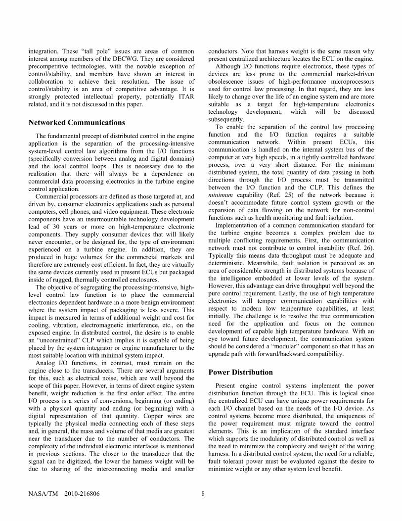
Figure 8.—The Fully Distributed Architecture represents a
mature distributed technology. It is enabled by high temperature embedded subsystems with significant control capability.
Fully Distributed Architecture
The Fully Distributed architecture, shown in Figure 8, represents the natural progression in capability of high temperature electronics as customer technology pull drives continuous improvement. At this future time, the advancements in electronics in the 300 to 500 C environment will no longer be performance limited relative to present day commercial silicon although the market size will still be relatively small. These electronics will bring high data processing capability to the engine environment although still lagging behind the capability of common commercial electronics. The major advancements in control capability will be in embedded control processing and high data rate communications above 300 C. This capability is expected to be achievable in a 15-year time frame.
In this architecture, the function of the data concentrator becomes obsolete as the communication capabilities of the smart devices enable them to communicate directly to the CLP. It is very likely that the communication medium will take advantage of wireless technology for the lowest possible control system weight. Of course, parasitic power technology would be required to make these devices viable.
The primary advantages of this architecture are; i) ultimate weight reduction of controls due to high-density, high-temperature electronics packaging, wireless networking, and parasitic power, ii) ubiquitous system knowledge due to near “weightless” wireless instrumentation embedded in components including the hot gas path, iii) very high reliability due to multipoint validation of system parameters.
Technical Challenges for Distributed Turbine Engine Control
Discussions within the DECWG have also revealed many of the most significant technical challenges that must be overcome to realize distributed engine control. These technical challenges are networked communications, power distribution, high temperature electronics, control/stability, and systems
Figure 7.—The Networked Control Architecture further
distributes control capability. It is enabled by embedded high temperature electronics in sensors and actuators.
NASA/TM—2010-216806 8
integration. These “tall pole” issues are areas of common interest among members of the DECWG. They are considered precompetitive technologies, with the notable exception of control/stability, and members have shown an interest in collaboration to achieve their resolution. The issue of control/stability is an area of competitive advantage. It is strongly protected intellectual property, potentially ITAR related, and it is not discussed in this paper.
Networked Communications
The fundamental precept of distributed control in the engine application is the separation of the processing-intensive system-level control law algorithms from the I/O functions (specifically conversion between analog and digital domains) and the local control loops. This is necessary due to the realization that there will always be a dependence on commercial data processing electronics in the turbine engine control application.
Commercial processors are defined as those targeted at, and driven by, consumer electronics applications such as personal computers, cell phones, and video equipment. These electronic components have an insurmountable technology development lead of 30 years or more on high-temperature electronic components. They supply consumer devices that will likely never encounter, or be designed for, the type of environment experienced on a turbine engine. In addition, they are produced in huge volumes for the commercial markets and therefore are extremely cost efficient. In fact, they are virtually the same devices currently used in present ECUs but packaged inside of rugged, thermally controlled enclosures.
The objective of segregating the processing-intensive, high-level control law function is to place the commercial electronics dependent hardware in a more benign environment where the system impact of packaging is less severe. This impact is measured in terms of additional weight and cost for cooling, vibration, electromagnetic interference, etc., on the exposed engine. In distributed control, the desire is to enable an “unconstrained” CLP which implies it is capable of being placed by the system integrator or engine manufacturer to the most suitable location with minimal system impact.
Analog I/O functions, in contrast, must remain on the engine close to the transducers. There are several arguments for this, such as electrical noise, which are well beyond the scope of this paper. However, in terms of direct engine system benefit, weight reduction is the first order effect. The entire I/O process is a series of conversions, beginning (or ending) with a physical quantity and ending (or beginning) with a digital representation of that quantity. Copper wires are typically the physical media connecting each of these steps and, in general, the mass and volume of that media are greatest near the transducer due to the number of conductors. The complexity of the individual electronic interfaces is mentioned in previous sections. The closer to the transducer that the signal can be digitized, the lower the harness weight will be due to sharing of the interconnecting media and smaller
conductors. Note that harness weight is the same reason why present centralized architecture locates the ECU on the engine.
Although I/O functions require electronics, these types of devices are less prone to the commercial market-driven obsolescence issues of high-performance microprocessors used for control law processing. In that regard, they are less likely to change over the life of an engine system and are more suitable as a target for high-temperature electronics technology development, which will be discussed subsequently.
To enable the separation of the control law processing function and the I/O function requires a suitable communication network. Within present ECUs, this communication is handled on the internal system bus of the computer at very high speeds, in a tightly controlled hardware process, over a very short distance. For the minimum distributed system, the total quantity of data passing in both directions through the I/O process must be transmitted between the I/O function and the CLP. This defines the minimum capability (Ref. 25) of the network because it doesn’t accommodate future control system growth or the expansion of data flowing on the network for non-control functions such as health monitoring and fault isolation.
Implementation of a common communication standard for the turbine engine becomes a complex problem due to multiple conflicting requirements. First, the communication network must not contribute to control instability (Ref. 26). Typically this means data throughput must be adequate and deterministic. Meanwhile, fault isolation is perceived as an area of considerable strength in distributed systems because of the intelligence embedded at lower levels of the system. However, this advantage can drive throughput well beyond the pure control requirement. Lastly, the use of high temperature electronics will temper communication capabilities with respect to modern low temperature capabilities, at least initially. The challenge is to resolve the true communication need for the application and focus on the common development of capable high temperature hardware. With an eye toward future development, the communication system should be considered a “modular” component so that it has an upgrade path with forward/backward compatibility.
Power Distribution
Present engine control systems implement the power distribution function through the ECU. This is logical since the centralized ECU can have unique power requirements for each I/O channel based on the needs of the I/O device. As control systems become more distributed, the uniqueness of the power requirement must migrate toward the control elements. This is an implication of the standard interface which supports the modularity of distributed control as well as the need to minimize the complexity and weight of the wiring harness. In a distributed control system, the need for a reliable, fault tolerant power must be evaluated against the desire to minimize weight or any other system level benefit.
NASA/TM—2010-216806 9
There are other implications as the power system becomes more distributed and is exposed to higher temperature environments. As with electronic components, temperature causes a de-rating of magnetic and other passive components which are used in power supplies. This could lead to problems with physical size or potential issues with electrical noise/susceptibility as switching supplies increase in frequency.
Most important, however, is the need to fully understand failure modes and the need to maintain, if not improve, overall system reliability.
High Temperature Electronics
The common thread in describing the physical implementation of a distributed control and power system is the high temperature capability of the electronic components. Fundamentally, distributed architecture is about modularity and the host of benefits that are realized because of it. For present and near-term engine systems, this modularity can provide real reductions in system design and upgrade time. In the long-term, distributed architecture is about preserving the capability to absorb growth in control requirements. However, if distributed architecture is to become a reality, it must do so without reducing present performance capability.
This implies that a distributed system must be implemented without a weight penalty with respect to traditional control architecture. The reduction in wire harness weight will be significant in a distributed system, but it will only create a weight benefit if the new distributed components are packaged using technology that enables a high degree of integration with little or no thermal accommodation for the ambient conditions.
Various electronic technologies do exist that have capability beyond the common 125 C junction temperature of commercial silicon. Some of this technology is commercially available now while even higher temperature technology is showing significant performance capability in research laboratories. For turbine-engine control systems, the specific electronic technology is not important; however, the capability that the technology brings to the engine system control is.
In the near-term, electronic temperature capabilities in the range of 225 C junction temperatures will provide sufficient capability for initial forays into distributed control architecture. This limitation will likely enable operation in an ambient environment below 170 C, which recognizes other constraints in the engine control system such as equipment fabricated with elastomers and aluminum. Much of the 225 C technology currently exists in the commercial sector, developed through previous programs such as the Department of Energy sponsored Deep-Trek program in the 1990’s. However, there are notable capabilities that still need development such as nonvolatile memory, improved processors, stable passive components and magnetics, and high-reliability interconnects.
As a whole, the electronics technology existing commercially is not properly packaged to meet the weight or reliability goals for distributed control in the turbine engine system. Improvements must be made in both the level of integration and the durability of parts in a high vibration environment.
In the long-term, temperature capabilities above 300 C are envisioned to enable fully embedded intelligent devices across the engine environment. This capability is at a significantly lower state of readiness but recent progress shows that the fundamental challenges are being resolved. Integrated electronic devices operating for extended duration (Ref. 27) at temperature as high as 500 C have been demonstrated.
Systems Integration
As previously stated, distributed architecture is fundamentally about modular systems. However, the development and use of modular systems is itself a technology that needs to be developed.
One of the primary cost drivers cited by industry is the flight certification process. Current engine systems require full requalification for new designs and modifications. In a modular distributed architecture, one of the main benefits, and reasons for industry participation, is the potential to qualify segments of the control system that are fully isolated from one another by means of digital communication and a rigidly controlled interface specification. Acceptance of these changes by regulatory agencies will require a significant burden of proof on the part of system designers and an arduous task of the adaptation of qualification processes and procedures.
Distributed systems present major changes to system design, integration, and verification processes and affects the relationship with suppliers. These represent a major shift in culture for the industry.
Development Plan
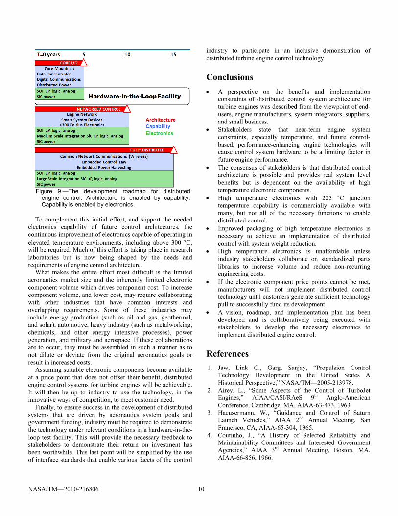
The progression of architectures described in the preceding section is used to generate a common diagram shown in Figure 9. To execute this roadmap will require a collaboration of government and industry that is designed to eliminate existing technology and cost barriers while enabling system-level competition and protection of intellectual property.
The focus of the collaboration will initially be on the development of an electronic parts library for engine control functions that will be capable of sustained operation in ambient temperatures found on the engine core. The electronic components for near-term architectures are being identified so that they can be developed and properly packaged to meet the environment, weight, cost, and reliability constraints of the turbine engine system. Use of common components does not preclude competition of system level design.
NASA/TM—2010-216806 10
To complement this initial effort, and support the needed electronics capability of future control architectures, the continuous improvement of electronics capable of operating in elevated temperature environments, including above 300 C, will be required. Much of this effort is taking place in research laboratories but is now being shaped by the needs and requirements of engine control architecture.
What makes the entire effort most difficult is the limited aeronautics market size and the inherently limited electronic component volume which drives component cost. To increase component volume, and lower cost, may require collaborating with other industries that have common interests and overlapping requirements. Some of these industries may include energy production (such as oil and gas, geothermal, and solar), automotive, heavy industry (such as metalworking, chemicals, and other energy intensive processes), power generation, and military and aerospace. If these collaborations are to occur, they must be assembled in such a manner as to not dilute or deviate from the original aeronautics goals or result in increased costs.
Assuming suitable electronic components become available at a price point that does not offset their benefit, distributed engine control systems for turbine engines will be achievable. It will then be up to industry to use the technology, in the innovative ways of competition, to meet customer need.
Finally, to ensure success in the development of distributed systems that are driven by aeronautics system goals and government funding, industry must be required to demonstrate the technology under relevant conditions in a hardware-in-the-loop test facility. This will provide the necessary feedback to stakeholders to demonstrate their return on investment has been worthwhile. This last point will be simplified by the use of interface standards that enable various facets of the control
industry to participate in an inclusive demonstration of distributed turbine engine control technology.
Conclusions
A perspective on the benefits and implementation constraints of distributed control system architecture for turbine engines was described from the viewpoint of end-users, engine manufacturers, system integrators, suppliers, and small business.
Stakeholders state that near-term engine system constraints, especially temperature, and future control-based, performance-enhancing engine technologies will cause control system hardware to be a limiting factor in future engine performance.
The consensus of stakeholders is that distributed control architecture is possible and provides real system level benefits but is dependent on the availability of high temperature electronic components.
High temperature electronics with 225 C junction temperature capability is commercially available with many, but not all of the necessary functions to enable distributed control.
Improved packaging of high temperature electronics is necessary to achieve an implementation of distributed control with system weight reduction.
High temperature electronics is unaffordable unless industry stakeholders collaborate on standardized parts libraries to increase volume and reduce non-recurring engineering costs.
If the electronic component price points cannot be met, manufacturers will not implement distributed control technology until customers generate sufficient technology pull to successfully fund its development.
A vision, roadmap, and implementation plan has been developed and is collaboratively being executed with stakeholders to develop the necessary electronics to implement distributed engine control.
References
1. Jaw, Link C., Garg, Sanjay, “Propulsion Control Technology Development in the United States A Historical Perspective,” NASA/TM—2005-213978.
2. Airey, L., “Some Aspects of the Control of TurboJet Engines,” AIAA/CASI/RAeS 9th Anglo-American Conference, Cambridge, MA, AIAA-63-473, 1963.
3. Haeusermann, W., “Guidance and Control of Saturn Launch Vehicles,” AIAA 2nd Annual Meeting, San Francisco, CA, AIAA-65-304, 1965.
4. Coutinho, J., “A History of Selected Reliability and Maintainability Committees and Interested Government Agencies,” AIAA 3rd Annual Meeting, Boston, MA, AIAA-66-856, 1966.
Figure 9.—The development roadmap for distributed
engine control. Architecture is enabled by capability. Capability is enabled by electronics.

NASA/TM—2010-216806 11
5. Peck, W.C., “Accelerating Reliability Growth of Electronic Propulsion Controls in the 1980’s,” AIAA/SAE/ASME 16th Joint Propulsion Conference, Hartford, CT, AIAA-80-1148, 1980.
6. Flanders, T.A., “The Inlet/Engine Control Vector,” AIAA 6th Propulsion Joint Specialist Conference, San Diego, CA, AIAA-70-696, 1970.
7. Weber, R.J., “Aeropropulsion in the Year 2000,” AIAA International Meeting & Technology Display “Global Technology 2000,” Baltimore, MD, AIAA-80-0914, 1980.
8. Kuhlberg, J.F., Newirth, D.M., “Digital Electronic Propulsion Control System Problems and Payoffs,” Journal of Aircraft, 1976, 0021-8669 vol.13 no.4 (279-285), doi: 10.2514/3.58656.
9. Barclay, B.A., “FADEC – Digital Propulsion Control of the Future,” AIAA/SAE 12th Propulsion Conference, Palo Alto, CA, AIAA-76-652, 1976.
10. Wanger, R.P., “Analog Vs. Digital Engine Control Tradeoff Considerations,” AIAA/SAE 12th Propulsion Conference, Palo Alto, CA, AIAA-76-650, 1976.
11. SMITH, T.B., “The Impact of Digital Computer Technology on Flight Systems,” Atmospheric Flight Mechanics Conference for Future Space Systems, Boulder, CO, AIAA-1979-1641, 1979.
12. Kuhlberg, J., Zimmerman, W., “Flight Testing of an All Electronic Propulsion Control System,” AIAA/SAE/ASME 16th Joint Propulsion Conference, Hartford. CT, AIAA-80-1147, 1980.
13. Barrett, W.J., et al, “Flight Test of a Full Authority Digital Electronic Engine Control Systems in an F-15 Aircraft,” AIAA/SAE/ASME 17th Joint Propulsion Conference, Colorado Springs, CO, AIAA-81-1501, 1981.
14. Myers, L., et al., “Flight Test Results of a Digital Electronic Engine Control System in an F-15 Airplane,” AIAA/SAE/ASME 18th Joint Propulsion Conference, Cleveland, OH, AIAA-82-1080, 1982.
15. Johnson, J.B., Nelson, J., “Flight Evaluation of the DEEC Secondary Engine Control Air-Start Capability,” NASA TM-84910, December 1983.
16. Cory, R., “Lessons Learned in the Development of a Digital Electronic Engine Control,” AIAA/SAE/ASME 20th Joint Propulsion Conference, Cincinnati, OH, AIAA-84-1335, 1984.
17. Fiebig, D., “Full Authority Digital Electronic Engine Control System Provides Needed Reliability,” AIAA/SAE/ASME/ASEE 26th Joint Propulsion Conference, Orlando, FL, AIAA 90-2037, 1990.
18. Merrill, W., “Sensor Failure Detection for Jet Engines Using Analytical Redundancy,” Journal of Guidance, Control, and Dynamics 1985, 0731-5090 vol.8 no.6 (673-682), doi: 10.2514/3.20041.
19. Lewis, T.J., “Highly Reliable, Microprocessor-based Engine Control,” AIAA/SAE/ASME/ASEE 23rd Joint Propulsion Conference, San Diego, CA, AIAA-87-1927, 1987.
20. Thomas, R.C., Conrad, R., Cording, R.W., “Reliability Assurance of Electronic Engine Controls,” AIAA/SAE/ASME 17th Joint Propulsion Conference, Colorado Springs, CO, AIAA-81-1499, 1981.
21. Soeder, J.F., “F100 Multivariable Control Synthesis Program,” NASA TP-2231, October 1983.
22. Painter, M.K., Erraguntla, M., Hogg, G.L. Jr., Beachkofski, B., “Using Simulation, Data Mining, and Knowledge Discovery Techniques for Optimized Aircraft Engine Fleet Management,” Proceeding of the 2006 Winter Simulation Conference, IEEE 2006.
23. Lee, K.C., Kim, M.H., Lee, S., Lee, H.H., “IEEE-1451-based Smart Module for In-vehicle Networking Systems of Intelligent Vehicles,” IEEE Transactions on Industrial Electronics, Volume 51, Issue 6, Dec. 2004 Page(s):1150 – 1158.
24. Culley, D., Paluszewski, P., Storey, W., Smith, B., “The Case for Distributed Engine Control in Turbo-Shaft Engine Systems,” 65th Annual Forum and Technology Display, American Helicopter Society, Grapevine, Texas, May 2009.
25. Culley, D., Behbahani, A., “Communication Needs Assessment for Distributed Turbine Engine Control,” 44th AIAA/ASME/SAE/ASEE Joint Propulsion Conference & Exhibit, Hartford, CT, AIAA-2008-5281, 2008.
26. Yedavalli, R., Belapurkar, R., Behbahani, A., “Design of Distributed Engine Control Systems for Stability Under Communication Packet Dropouts,” Journal of Guidance, Control, and Dynamics 2009, 0731-5090 vol.32 no.5 (1544-1549) doi: 10.2514/1.40900.
27. Neudeck, P.G., Spry, D.J., Chen, L.Y., et al., “6H-SiC Transistor Integrated Circuits Demonstrating Prolonged Operation at 500 C,” IMAPS International Conference and Exhibition on High Temperature Electronics (HiTEC 2008), May 12–15, 2008, Albuquerque, New Mexico.
REPORT DOCUMENTATION PAGE Form Approved
OMB No. 0704-0188 The public reporting burden for this collection of information is estimated to average 1 hour per response, including the time for reviewing instructions, searching existing data sources, gathering and maintaining the data needed, and completing and reviewing the collection of information. Send comments regarding this burden estimate or any other aspect of this collection of information, including suggestions for reducing this burden, to Department of Defense, Washington Headquarters Services, Directorate for Information Operations and Reports (0704-0188), 1215 Jefferson Davis Highway, Suite 1204, Arlington, VA 22202-4302. Respondents should be aware that notwithstanding any other provision of law, no person shall be subject to any penalty for failing to comply with a collection of information if it does not display a currently valid OMB control number. PLEASE DO NOT RETURN YOUR FORM TO THE ABOVE ADDRESS.
1. REPORT DATE (DD-MM-YYYY) 01-09-2010
2. REPORT TYPE Technical Memorandum
3. DATES COVERED (From - To)
4. TITLE AND SUBTITLE Transition in Gas Turbine Control System Architecture: Modular, Distributed, and Embedded
5a. CONTRACT NUMBER
5b. GRANT NUMBER
5c. PROGRAM ELEMENT NUMBER
6. AUTHOR(S) Culley, Dennis
5d. PROJECT NUMBER
5e. TASK NUMBER
5f. WORK UNIT NUMBER WBS 561581.02.08.03.17.03
7. PERFORMING ORGANIZATION NAME(S) AND ADDRESS(ES) National Aeronautics and Space Administration John H. Glenn Research Center at Lewis Field Cleveland, Ohio 44135-3191
8. PERFORMING ORGANIZATION REPORT NUMBER E-17438
9. SPONSORING/MONITORING AGENCY NAME(S) AND ADDRESS(ES) National Aeronautics and Space Administration Washington, DC 20546-0001
10. SPONSORING/MONITOR'S ACRONYM(S) NASA
11. SPONSORING/MONITORING REPORT NUMBER NASA/TM-2010-216806
12. DISTRIBUTION/AVAILABILITY STATEMENT Unclassified-Unlimited Subject Category: 07 Available electronically at http://gltrs.grc.nasa.gov This publication is available from the NASA Center for AeroSpace Information, 443-757-5802
13. SUPPLEMENTARY NOTES
14. ABSTRACT Controls systems are an increasingly important component of turbine-engine system technology. However, as engines become more capable, the control system itself becomes ever more constrained by the inherent environmental conditions of the engine; a relationship forced by the continued reliance on commercial electronics technology. A revolutionary change in the architecture of turbine-engine control systems will change this paradigm and result in fully distributed engine control systems. Initially, the revolution will begin with the physical decoupling of the control law processor from the hostile engine environment using a digital communications network and engine-mounted high temperature electronics requiring little or no thermal control. The vision for the evolution of distributed control capability from this initial implementation to fully distributed and embedded control is described in a roadmap and implementation plan. The development of this plan is the result of discussions with government and industry stakeholders.15. SUBJECT TERMS Engine control; Distributed control; High temperature electronics
16. SECURITY CLASSIFICATION OF: 17. LIMITATION OF ABSTRACT UU
18. NUMBER OF PAGES
17
19a. NAME OF RESPONSIBLE PERSON STI Help Desk (email:[email protected])
a. REPORT U
b. ABSTRACT U
c. THIS PAGE U
19b. TELEPHONE NUMBER (include area code) 443-757-5802
Standard Form 298 (Rev. 8-98)Prescribed by ANSI Std. Z39-18