transition strategies for iec 61850”implementing iec 61850 within a utility is not necessarily...
TRANSCRIPT

Paul Myrda Scott Sternfeld Technical Executive Project Manager
February IntelliGrid Smart Grid Informational Webcast
February 26, 2013
"Transition Strategies for IEC 61850”
2 © 2012 Electric Power Research Institute, Inc. All rights reserved.
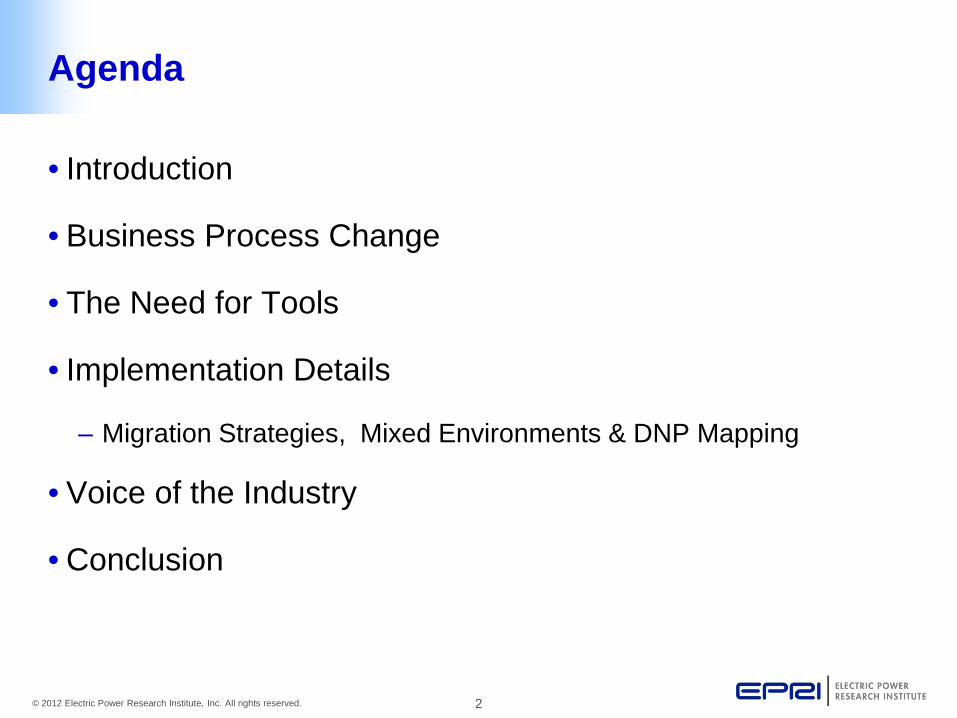
Agenda
• Introduction
• Business Process Change
• The Need for Tools
• Implementation Details
– Migration Strategies, Mixed Environments & DNP Mapping
• Voice of the Industry
• Conclusion

3 © 2012 Electric Power Research Institute, Inc. All rights reserved.
• Utility Current State – Adoption rates of IEC 61850 continue to increase in
North America and across the globe – The use of GOOSE for protection, control and
automation was well established, and use within critical protection applications was being widely adopted as well.
– Most implementations described were occurring in “Greenfield” installations rather than upgrades of existing stations, and in these cases, IEC 61850 was typically being used to the exclusion of all other protocols.
Introduction
4 © 2012 Electric Power Research Institute, Inc. All rights reserved.
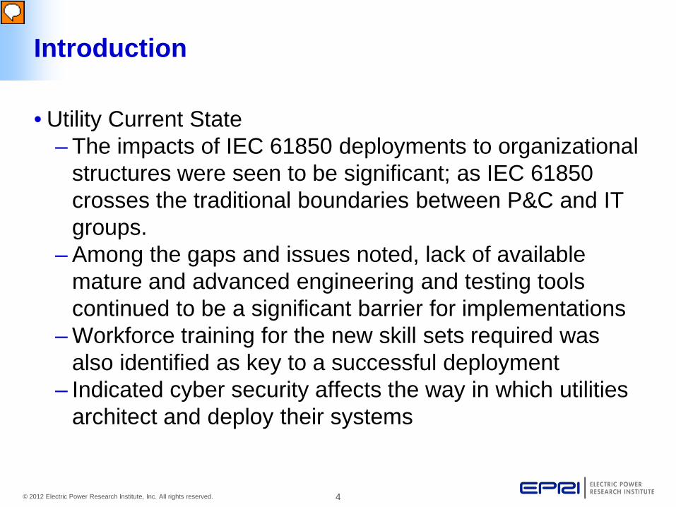
• Utility Current State – The impacts of IEC 61850 deployments to organizational
structures were seen to be significant; as IEC 61850 crosses the traditional boundaries between P&C and IT groups.
– Among the gaps and issues noted, lack of available mature and advanced engineering and testing tools continued to be a significant barrier for implementations
– Workforce training for the new skill sets required was also identified as key to a successful deployment
– Indicated cyber security affects the way in which utilities architect and deploy their systems
Introduction

5 © 2012 Electric Power Research Institute, Inc. All rights reserved.
• Utility Current State – Costs and benefits continue to be refined as more
utilities gain experience with IEC 61850. – Organizational commitment is essential for any IEC
61850 deployment – Full understanding of the true benefits of the IEC 61850
technology are just beginning to emerge and further monitoring of implementation progress is warranted.
Introduction

6 © 2012 Electric Power Research Institute, Inc. All rights reserved.
• Several issues that remain are: – Impact on the organizational structures – Lack of mature and advanced engineering and testing
tools – Vendor independent (or multi vendor capable) tools are
needed to aid integration, commissioning and maintenance activities.
– Workforce training for the new skill sets required is critical to a successful deployment.
– Workforce training regarding design/deployment of IEC 61850 from a testability perspective.
– Organizational commitment is essential
Introduction

7 © 2012 Electric Power Research Institute, Inc. All rights reserved.
• Review of Typical Process – Legacy Process
Business Process Change
Sample Legacy Relay Setting Sheet

8 © 2012 Electric Power Research Institute, Inc. All rights reserved.
• Review of Typical Process – Newer Method
Business Process Change
STATION: Substation
DEVICE: 11 BREAKER: OR762
RELAY #: R-99872
REMOTE: TX bank 1
NAME: Protection Engineer
FIRMWARE: MFR-999-2-R505-V0-Z103103-D2
Part #: MFR99921325H6X4X1
SERIAL #: 2012282270
IP Address: N/A
Sample Spreadsheet Logical Cell Linkages

9 © 2012 Electric Power Research Institute, Inc. All rights reserved.
• Review of Typical Process – Newest Method
• Advanced Systems for Power Engineering, Inc. (ASPEN)
http://www.aspeninc.com
• CAPE (Computer-Aided Protection Engineering) software http://www.electrocon.com from Electrocon International, Inc
Business Process Change

10 © 2012 Electric Power Research Institute, Inc. All rights reserved.
• IEC 61850 Process – Part 4 of the standard entitled System and Project
Management specifies the following (4): • The specifications of this part pertain to the system and project management with respect to:
– the engineering process and its supporting tools; – the life cycle of the overall system and its IEDs; – the quality assurance beginning with the
development stage and ending with discontinuation and decommissioning of the UAS and its IEDs.
The Need for Tools

11 © 2012 Electric Power Research Institute, Inc. All rights reserved.
• IEC 61850 Process - Classification • Parameters are data, which control and support the operation of:
– hardware configuration (composition of IEDs); – software of IEDs; – process environment (primary equipment and
auxiliaries); – HMI with different supporting tools; and – telecommunication environment
in an automation system and its IEDs in such a way that the operations of the plant and customer specific requirements are fulfilled.
The Need for Tools

12 © 2012 Electric Power Research Institute, Inc. All rights reserved.
• IEC 61850 Process – Structure of UAS and IED parameters
The Need for Tools
UAS - parameter set
IED1 - parameter set IEDn - parameter set
Configuration parameters Operating parameters
System parameters Process parameters Functional parameters
Switchable parameters Non-switchable parameters
IEC 105/02

13 © 2012 Electric Power Research Institute, Inc. All rights reserved.
• IEC 61850 Process – Engineering Process Actors
The Need for Tools
• System planner • Substation planner • System / plant engineer for secondary equipment • Project / design engineer for secondary equipment • System integrator • Device (IED) parameter setting engineer • Construction engineer • System verification engineer • Device tester • Assembly, installation technician • Commissioning engineer

14 © 2012 Electric Power Research Institute, Inc. All rights reserved.
• Reference model for information flow in the configuration process
The Need for Tools
Current Providers of SCL Tools
Helinks - www.helinks.com.
Kalkitech - www.kalkitech.com
Pullnet Co - www.pullnet.com/atlan

15 © 2012 Electric Power Research Institute, Inc. All rights reserved.
• Typically a utility will develop a set of protection standards
Example Utility Process
For example 345/138KV autotransformer Standard Transformer Unit design

16 © 2012 Electric Power Research Institute, Inc. All rights reserved.
• These utility specific standards get applied, as applicable, to modifications in the primary system. So in the case of a 345/138KV autotransformer addition they would apply the 345/138KV Standard Transformer Unit design. In this case that would consist of the following specific utility standards: – 345KV Primary Differential – Overall – 138KV Primary Differential – Transformer Bank – 345KV Back-up – 138KV Backup
The Need for Tools

17 © 2012 Electric Power Research Institute, Inc. All rights reserved.
The Need for Tools
EngineeringWorkplace
EngineeringWorkplace
Non- Vendor Specific Templates and Associated Generic Design Drawings
Vendor Specific Templates and Associated Vendor Specific Design Drawings
Non- Vendor Specific Templates and Associated Generic Design Drawings
“Vendor Specific Templates and Associated Vendor Specific
Design Drawings”.

18 © 2012 Electric Power Research Institute, Inc. All rights reserved.
Lockout Relay Example
Legacy drawing based approach needs to be replaced by linked automated approach

19 © 2012 Electric Power Research Institute, Inc. All rights reserved.
Example Logic Diagram for Distributed Lockout
LATCH
SET
RESET
ON
OFF
LATCH
SET
RESET
ON
OFF
LATCHSET
RST
ON
LATCHSET
RST
OFF
ON
OFF
LATCHSET
RST
ON
OFF
LATCHSET
RST
ON
OFF
LATCHSET
RST
ON
OFF
AND
OR
87T-1
86T-1 RST PB
87T-2
86T-2 RST PB
CB1 BFP-1
BFP-1 RST PB
BFP-3
BFP-3 RST PB
BFP-4
BFP-4 RST PB
LATCHSET
RST
ON
OFF
LATCHSET
RST
ON
OFF
LATCHSET
RST
ON
OFF
LATCHSET
RST
ON
OFF
LATCHSET
RST
ON
OFF
CB1 BFP-2
BFP-2 RST PB
AND
OR
TC1
ORLATCHSET
RST
ON
AND OR
MASTERLOCKOUT
RST/PASSWORDPROTECTED/
ORLATCHSET
RST
AND OR
TC1
TC2
ON CLOSE BLOCK
CLOSE BLOCK
TC2
D60-1/345
T60-
2LO
CA
L H
MI
D60
-1/
345
D60
-1/
138
D60
-2/
138
D60
-2/3
45T6
0-1
138kV CB2
138kV CB2
345kV CB1
345kV CB1
New method needs to be able to develop utility standard models that can be transferred into a vendor specific implementation

Migration Strategies, Mixed Environments & DNP Mapping
Scott Sternfeld
Implementation Details

21 © 2012 Electric Power Research Institute, Inc. All rights reserved.
Mixed 61850/DNP environment

22 © 2012 Electric Power Research Institute, Inc. All rights reserved.
Mixed 61850/DNP environment

23 © 2012 Electric Power Research Institute, Inc. All rights reserved.
Cabling options: converters/adapters

24 © 2012 Electric Power Research Institute, Inc. All rights reserved.
Migration strategies

25 © 2012 Electric Power Research Institute, Inc. All rights reserved.
Naming convention: “Tag Name”
• Create a naming convention for DNP points to mimic names when IEC 61850 devices are used. (Similar to CID or ICD file)
• Should follow edition 2 of the IEC 61850 naming standard since it provides for a more detailed definition of the data-point names and for a broader range of devices and signals.
• Sample arrangement: Substation name or number, line voltage, protection circuit, device identification, and IEC 61850 data point. – SUB_LINEVOLT_PROTID_DEVID/YLTC.TapPos.stINum – SUB_LINEVOLT_PROTID_DEVID/MMXU.totW.mag – SUB_LINEVOLT_PROTID_DEVID/ZBAT.BatFail.stVal – SUB_LINEVOLT_PROTID_DEVID/MMXU1.PPV.phsAB.mag
User defined Defined in IED

26 © 2012 Electric Power Research Institute, Inc. All rights reserved.
Naming convention limitations
• Testing in EPRI Smart Grid Substation Lab verified some vendor name length limitations varying from 44, 66 or 255 characters.
Examples: DEVPREFIX_LINEVOLT_PROTID_DEVID/MMXU1.PPV.phsAB.mag
(51 characters)
Would need to be reduced to the following: PX_LINEVOLT_PROTID_DEVID/MMXU1.PPV.phsAB.mag
(44 characters)

27 © 2012 Electric Power Research Institute, Inc. All rights reserved.
IEEE P1815.1: DNP61850 mapping
Draft Standard for Exchanging Information between networks implementing IEC 61850 and IEEE Std 1815 (DNP3) • This document specifies the standard approach for mapping
between IEEE Std 1815 (Distributed Network Protocol (DNP3)) and IEC 61850 (Communications Networks and Systems for Power Utility Automation). Two primary use cases are addressed; – (A) Mapping between an IEEE Std 1815 based master
and an IEC 61850 based substation LAN and – (B) Mapping between an IEC 61850 based master and an
IEEE Std 1815 based substation LAN.

28 © 2012 Electric Power Research Institute, Inc. All rights reserved.
P1815.1 – PAR Scope Change
• Mapping aspects included in the standard are: conceptual architecture; general mapping requirements; the mapping of Common Data Classes, Constructed Attribute Classes and Abstract Communication Service Interface (ASCI); cyber security requirements, the architecture of a gateway used for translation and requirements for embedding mapping configuration information into IEC 61850 Substation Configuration Language (SCL) and DNP‐Profile.
• This specification addresses a selection of features, data classes and services of the two standards.

29 © 2012 Electric Power Research Institute, Inc. All rights reserved.
Use Case (a): DNP to 61850

30 © 2012 Electric Power Research Institute, Inc. All rights reserved.
Figure 29— Direct Control, Normal Security, Use Case (a) – Positive Case
Note - Figure Reference from IEEE P1815.1/D4.00, June 2012

31 © 2012 Electric Power Research Institute, Inc. All rights reserved.
Figure 47— SBO Control, Normal Security, Use Case (a) – Positive Case
Note - Figure Reference from IEEE P1815.1/D4.00, June 2012

32 © 2012 Electric Power Research Institute, Inc. All rights reserved.
Use Case (b): 61850 to DNP

33 © 2012 Electric Power Research Institute, Inc. All rights reserved.
Figure 33— Direct Control, Normal Security, Use Case (b) – Positive Case
Note - Figure Reference from IEEE P1815.1/D4.00, June 2012

34 © 2012 Electric Power Research Institute, Inc. All rights reserved.
Figure 53— SBO Control, Normal Security, Use Case (b) – Positive Case
Note - Figure Reference from IEEE P1815.1/D4.00, June 2012

35 © 2012 Electric Power Research Institute, Inc. All rights reserved.
“Enhanced security”
• IEC 61850-7-2 permits controls with enhanced security, meaning that after sending a response to the control request, the server waits for a physical indication that the control has operated before sending a CmdTerm message. The corresponding component in DNP3 is an Output Event. There are two concerns with this mapping of CmdTerm to Output Event:
– Both IEC 61850-7-2 enhanced security and DNP3 Output Events are optional. They shall always be used together. If one side of the gateway does not support enhanced security, the other shall not use it. The client or master shall never be promised a level of reliability that the other side of the gateway cannot support.
– DNP3 has no equivalent for a negative CmdTerm message. Using DNP3 the gateway can only confirm that the control successfully operated. The gateway cannot notify the DNP3 master that the control did not operate. In use case (a), the DNP3 master has no method to determine that the control did not operate other than to time out waiting for the Output Event. In use case (b), the IEC 61850-7-2 client similarly has no alternative other than to time out waiting for the negative CmdTerm message because the DNP3 IEDs cannot send a negative indication to the gateway.

Paul Myrda
Voice of the Industry

37 © 2012 Electric Power Research Institute, Inc. All rights reserved.
Voice of the Industry
• Chart of IEC 61850 Major Implementation Obstacles – 61850 Group
0% 5% 10% 15% 20% 25% 30% 35% 40% 45% 50%
4%
9%
13%
31%
40%

38 © 2012 Electric Power Research Institute, Inc. All rights reserved.
• Chart of IEC 61850 Major Implementation Obstacles – PSPE Group
Voice of the Industry
0% 5% 10% 15% 20% 25% 30% 35% 40% 45% 50%
0%
0%
9%
45%
45%

39 © 2012 Electric Power Research Institute, Inc. All rights reserved.
Other References
Study Committee B5 Colloquium 2011 September 12-17 Lausanne, SWITZERLAND
SPECIAL REPORT FOR STUDY COMMITTEE B5 (Protection and Automation) PS1: IEC 61850: Which tools for which user? Anders JOHNSSON (Sweden)
• PACWorld - http://www.pacw.org/ – Frequent articles on IEC 61850

40 © 2012 Electric Power Research Institute, Inc. All rights reserved.
Good reference
• Engineering Guidelines for IEC 61850 Based Digital SAS
• CIGRE Report 466 – June 2011 • Working Group - B5.12 • Members
Javier Castellanos (ES), Anders Johnsson (SE), Ksenija Žubrinic (HR), Claude Racine (CH), Rodolfo Pereda (ES), Daniel Espinosa (MX), Allan Cascaes (BR), Rogério Dias Paulo (PT), Phil Beaumont (UK), Luc Hossenlopp (FR), Craig McTaggart (UK), Julio Pérez (AR), Daniel Mellado (AR), Mathias Grädler (FI), Darren Webb (UK), Jukka Tuukkanen (FI), Ignacio Garcés (ES), Juergen Heckel (DE), Bogdan Kasztenny (CA), Keiichi Kaneda (JP), Yan-ming Ren (CN), Zhang Jie (CN), Ho-Yeup Song (Korea)

41 © 2012 Electric Power Research Institute, Inc. All rights reserved.
• IEC 61850 continues to gain ground and improve with each installation.
• The only way for IEC 61850 to improve is through utility applications and feedback to the standards body on issues.
• As the market expands , vendors will enhance the tools needed to facilitate the processes
Recent EPRI Reports – 1024299-IEC 61850 Implementation – 1024300-Transition from Legacy Protocols to IEC61850
Conclusion

42 © 2012 Electric Power Research Institute, Inc. All rights reserved.
Together…Shaping the Future of Electricity