transmitter transmisor - minimed insulin … · 2016-11-30 · the medtronic minilink® transmitter...
TRANSCRIPT

®
TRANSMITTERTRANSMISOR
MP6025647-2AF1 / A
RELEASED

MP6025647-2AF1 / A
RELEASED

The Medtronic MiniLink® transmitter is a component of select continuous glucosesensing systems and the MiniMed® 530G insulin pump. The transmitter powers theglucose sensor, collects glucose data, and wirelessly sends the data to a MiniMed530G insulin pump.
A complete MiniLink kit includes:• MiniLink transmitter (MMT-7703)• Tester (MMT-7706)• Sensor insertion device
• Blue charger (MMT-7705)• AAA or LR-03 alkaline battery(ies)
Indications for useThe transmitter is indicated for use as a component of select Medtronic continuousglucose sensing systems and the MiniMed 530G insulin pump.
ContraindicationsNone known.
WarningsProduct contains small parts and may pose a choking hazard for young children.The sensor should be removed if redness, bleeding, pain, tenderness, irritation, orinflammation develops at the insertion site, or if you experience unexplained fever.The optional occlusive dressing should be removed if irritation or reaction develops.Bleeding may occur after inserting the sensor. Make sure that the site is not bleedingbefore connecting the transmitter to the sensor.• If bleeding occurs, apply steady pressure with a sterile gauze or clean cloth at
the insertion site until bleeding stops. After bleeding stops, connect thetransmitter to the sensor.
• If bleeding persists after three minutes, remove the sensor and discard. Insert anew sensor in a different location.
-1-
EnglishMP6025647-2AF1 / A
RELEASED
Contact the 24 Hour HelpLine if you experience any adverse reactions associated withthe transmitter or sensor.
Magnetic fieldsDo not expose your transmitter to MRI equipment, diathermy devices, or other devicesthat generate strong magnetic fields. If your transmitter is inadvertently exposed to astrong magnetic field, discontinue use and contact the 24 Hour HelpLine for furtherassistance.
X-rays, MRIs, and CT scansIf you are going to have an X-ray, CT scan, MRI, or other type of exposure to radiation,disconnect your transmitter and remove your sensor before entering a room that containsany of this equipment.Important information about airport security systems, and using your insulin pump on anairplane, can be found on the Emergency Card. Be sure to carry the Emergency Cardprovided when you are traveling.
PrecautionsEstablish a rotation schedule for choosing new sensor sites. Avoid sites that areconstrained by clothing, have scar tissue, or are subject to rigorous movement duringexercise.
NoticeThis device complies with the United States Federal Communications Commission (FCC)and international standards for electromagnetic compatibility.This device complies with Part 15 Rules. Operation is subject to the following twoconditions: (1) this device may not cause harmful interference, and (2) this device mustaccept any interference received, including interference that may cause undesirableoperation.The transmitter does not interfere with any radio frequency signals transmitted fromoutside sources. These FCC standards are designed to provide reasonable protectionagainst excessive radio frequency interference and prevent undesirable operation of thedevice from unwanted electromagnetic interference.Important: Changes or modifications not expressly approved by the partyresponsible for compliance could void the user’s authority to operate theequipment.
-2-
MP6025647-2AF1 / A
RELEASED
RF interference from other devicesCommon consumer electronic devices that transmit in the same frequency band usedby the transmitter may prevent the receiving device (MiniMed 530G insulin pump)from receiving the glucose information sent by the transmitter. Most cellular (mobile)phones and 900 MHz cordless phones, when transmitting or receiving, may causesignificant interruption of transmitter-receiver communication. It is likely that otherdevices operating in similar frequency ranges will have a similar effect. Thisinterference, however, will not cause any incorrect data to be sent and will not causeany harm to your transmitter.MiniMed 530G insulin pumps include a programmable “Weak Signal” alert thatnotifies you when one or more transmitter transmissions were not received asexpected by the receiving device. (The receiving device will also issue a “LostSensor” alert if communication is interrupted for approximately 40 minutes.)Communication problems can typically be resolved by ensuring that the distancebetween transmitter and receiving device is less than six feet (1.8 meters), and byturning off or moving away from other RF transmitting devices. You can also reorientor relocate the transmitter and/or the receiving device to try to correct theinterference. Testing conducted with several different cellular phones suggests thatinterference will not be a problem if the phone is at least 12 inches (31 cm) from thetransmitter or receiving device while it is being used (greater separation distance maybe required for certain devices).
AssistanceMedtronic MiniMed provides a 24 Hour HelpLine for assistance. The HelpLine isstaffed with representatives who are trained in the set-up and operation of your CGMsystem. When calling the HelpLine, please have your pump serial number available.Your pump serial number and the 24 Hour HelpLine phone number are listed on theback of your device.
Department Telephone number24 Hour HelpLine (calls within the United States) 800 646 4633
24 Hour HelpLine (calls outside the United States) +1 818 576 5555
Web site www.medtronicdiabetes.com
-3-
EnglishMP6025647-2AF1 / A
RELEASED
ChargerThe transmitter contains a non-replaceable, rechargeable battery that you can rechargeas needed with the charger. The charger has a green light that shows the charging statusand a red light that communicates any problems during charging. If you see a red light,see the Troubleshooting section. The charger needs one AAA alkaline battery, size E92,type LR03 (Energizer brand recommended) to operate.
Note: A new AAA or LR-03 battery contains enough power to recharge the transmittermore than 40 times. If the battery is installed incorrectly or is low, the charger willnot work. Repeat the battery installation steps using a new battery.
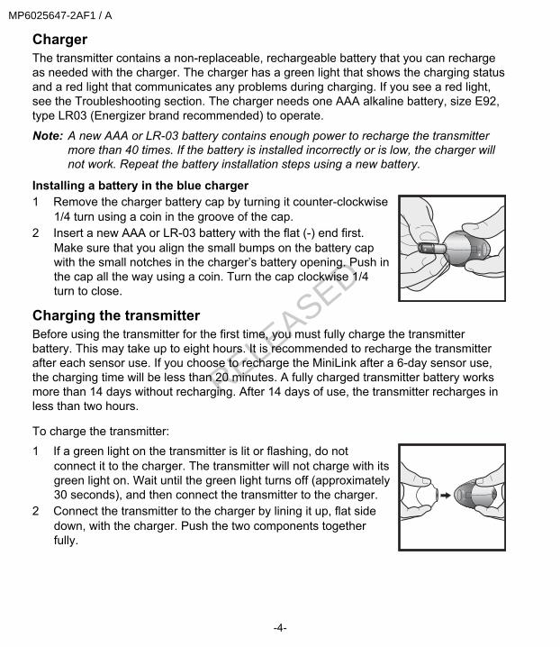
Installing a battery in the blue charger1 Remove the charger battery cap by turning it counter-clockwise
1/4 turn using a coin in the groove of the cap.2 Insert a new AAA or LR-03 battery with the flat (-) end first.
Make sure that you align the small bumps on the battery capwith the small notches in the charger’s battery opening. Push inthe cap all the way using a coin. Turn the cap clockwise 1/4turn to close.
Charging the transmitterBefore using the transmitter for the first time, you must fully charge the transmitterbattery. This may take up to eight hours. It is recommended to recharge the transmitterafter each sensor use. If you choose to recharge the MiniLink after a 6-day sensor use,the charging time will be less than 20 minutes. A fully charged transmitter battery worksmore than 14 days without recharging. After 14 days of use, the transmitter recharges inless than two hours. To charge the transmitter:1 If a green light on the transmitter is lit or flashing, do not
connect it to the charger. The transmitter will not charge with itsgreen light on. Wait until the green light turns off (approximately30 seconds), and then connect the transmitter to the charger.
2 Connect the transmitter to the charger by lining it up, flat sidedown, with the charger. Push the two components togetherfully.
-4-
MP6025647-2AF1 / A
RELEASED
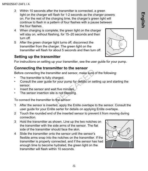
3 Within 10 seconds after the transmitter is connected, a greenlight on the charger will flash for 1-2 seconds as the charger powerson. For the rest of the charging time, the charger’s green light willcontinue to flash in a pattern of four flashes with a pause betweenthe four flashes.
4 When charging is complete, the green light on the chargerwill stay on, without flashing, for 15–20 seconds and thenturn off.
5 After the green charger light turns off, disconnect thetransmitter from the charger. The green light on thetransmitter will flash for about 5 seconds and then turn off.
Setting up the transmitterFor instructions on setting up your transmitter, see the user guide for your pump.
Connecting the transmitter to the sensorBefore connecting the transmitter and sensor, make sure of the following:• The transmitter is fully charged.• Consult the user guide for your pump for details on setting up and starting the
sensor.• Insert the sensor and wait five minutes.• The sensor insertion site is not bleeding. To connect the transmitter to the sensor:1 After the sensor is inserted, apply the Enlite overtape to the sensor. Consult the
user guide for your Enlite serter for details on applying Enlite overtape.2 Touch the rounded end of the inserted sensor to prevent it from moving during
connection.3 Hold the transmitter as shown. Line up the two notches on
the transmitter with the side arms of the sensor. The flatside of the transmitter should face the skin.
4 Slide the transmitter onto the sensor until the sensor’sflexible arms snap into the notches on the transmitter. If thetransmitter is properly connected, and if the sensor has hadenough time to become hydrated, the green light on thetransmitter will flash within 10 seconds.
-5-
EnglishMP6025647-2AF1 / A
RELEASED
5 If the transmitter light does not flash, disconnect it from the sensor, wait for severalseconds and then reconnect. If the transmitter light still does not flash, charge thetransmitter.
6 After the transmitter light flashes green, use your pump to communicate with thesensor. For more instructions, see the user guide for your pump.
7 After the transmitter successfully sends sensor data to the pump, attach the adhesivetab from the Enlite sensor (MMT-7008) to the transmitter.
8 [Optional]: Apply occlusive dressing over the transmitter and the sensor.
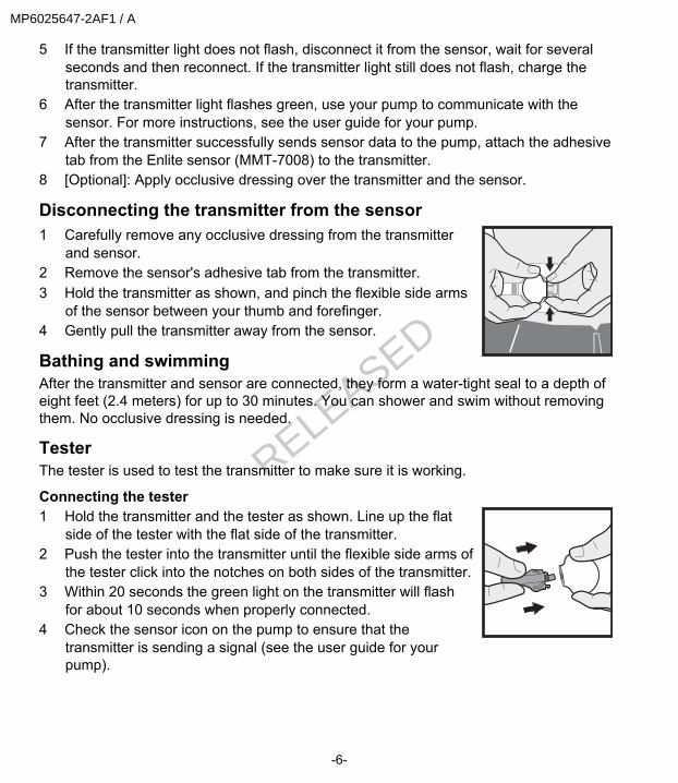
Disconnecting the transmitter from the sensor1 Carefully remove any occlusive dressing from the transmitter
and sensor.2 Remove the sensor's adhesive tab from the transmitter.3 Hold the transmitter as shown, and pinch the flexible side arms
of the sensor between your thumb and forefinger.4 Gently pull the transmitter away from the sensor.
Bathing and swimmingAfter the transmitter and sensor are connected, they form a water-tight seal to a depth ofeight feet (2.4 meters) for up to 30 minutes. You can shower and swim without removingthem. No occlusive dressing is needed.
TesterThe tester is used to test the transmitter to make sure it is working.
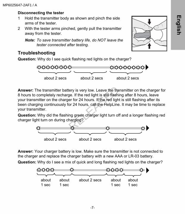
Connecting the tester1 Hold the transmitter and the tester as shown. Line up the flat
side of the tester with the flat side of the transmitter.2 Push the tester into the transmitter until the flexible side arms of
the tester click into the notches on both sides of the transmitter.3 Within 20 seconds the green light on the transmitter will flash
for about 10 seconds when properly connected.4 Check the sensor icon on the pump to ensure that the
transmitter is sending a signal (see the user guide for yourpump).
-6-
MP6025647-2AF1 / A
RELEASED
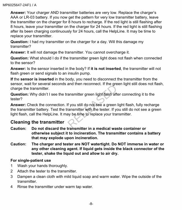
Disconnecting the tester1 Hold the transmitter body as shown and pinch the side
arms of the tester.2 With the tester arms pinched, gently pull the transmitter
away from the tester.
Note: To save transmitter battery life, do NOT leave thetester connected after testing.
TroubleshootingQuestion: Why do I see quick flashing red lights on the charger?
about 2 secs about 2 secs about 2 secs
Answer: The transmitter battery is very low. Leave the transmitter on the charger for8 hours to completely recharge. If the red light is still flashing after 8 hours, leaveyour transmitter on the charger for 24 hours. If the red light is still flashing after itsbeen charging continuously for 24 hours, call the HelpLine. It may be time to replaceyour transmitter.Question: Why did the flashing green charger light turn off and a longer flashing redcharger light turn on during charging?
about 2 secs about 2 secs about 2 secs
Answer: Your charger battery is low. Make sure the transmitter is not connected tothe charger and replace the charger battery with a new AAA or LR-03 battery.Question: Why do I see a mix of quick and long flashing red lights on the charger?
about 2 secsabout 1 sec
about 1 sec
about 1 sec
about 1 sec
-7-
EnglishMP6025647-2AF1 / A
RELEASED
Answer: Your charger AND transmitter batteries are very low. Replace the charger’sAAA or LR-03 battery. If you now get the pattern for very low transmitter battery, leavethe transmitter on the charger for 8 hours to recharge. If the red light is still flashing after8 hours, leave your transmitter on the charger for 24 hours. If the red light is still flashingafter its been charging continuously for 24 hours, call the HelpLine. It may be time toreplace your transmitter.Question: I had my transmitter on the charger for a day. Will this damage mytransmitter?Answer: It will not damage the transmitter. You cannot overcharge it.Question: What should I do if the transmitter green light does not flash when connectedto the sensor?Answer: Is the sensor inserted in the body? If it is not inserted, the transmitter will notflash green or send signals to an insulin pump.If the sensor is inserted in the body, you need to disconnect the transmitter from thesensor, wait for several seconds and then reconnect. If the green light still does not flash,charge the transmitter.Question: Why didn’t I see the transmitter green light flash after connecting it to thetester?Answer: Check the connection. If you still do not see a green light flash, fully rechargethe transmitter battery. Test the transmitter with the tester. If you still do not see a greenlight flash, call the HelpLine. It may be time to replace your transmitter.
Cleaning the transmitterCaution: Do not discard the transmitter in a medical waste container or
otherwise subject it to incineration. The transmitter contains a batterythat may explode upon incineration.
Caution: The charger and tester are NOT watertight. Do NOT immerse in water orany other cleaning agent. If liquid gets inside the black connector of thetester, shake the liquid out and allow to air dry.
For single-patient use1 Wash your hands thoroughly.2 Attach the tester to the transmitter.3 Dampen a clean cloth with mild liquid soap and warm water. Wipe the outside of the
transmitter.4 Rinse the transmitter under warm tap water.
-8-
MP6025647-2AF1 / A
RELEASED
5 Using an antibacterial hand-sanitizer (available at a local drugstore) on a clean,dry cloth, wipe the transmitter’s surface. Do NOT get any hand-sanitizer insidethe tester opening or transmitter connector. Repeated exposure to hand-sanitizercould damage the connectors and affect the transmitter’s performance as aresult. If you get hand-sanitizer inside the tester or connector, allow them to airdry.
6 Disconnect the tester from the transmitter.7 Place the transmitter on a clean, dry cloth and air dry for 2–3 minutes.
For multiple-patient useCaution: The charger and tester are NOT watertight. Do NOT immerse in
water or any other cleaning agent. If liquid gets inside the blackconnector of the tester, shake the liquid out and allow to air dry.
Warning: Always clean the transmitter after removing it from the patient andbefore attaching it to the charger. If there is any blood inside theconnector, the transmitter must be discarded.Dispose the transmitter according to the local regulations forbattery disposal (non- incineration).
Follow this procedure to clean the transmitter after each patient use:1 Wash your hands thoroughly.2 Attach the tester to the transmitter.3 Dampen a clean cloth with mild liquid soap and warm water. Wipe the outside of
the transmitter.4 Rinse the transmitter under warm tap water.5 Apply 3-4 drops of a quaternary ammonium compound disinfectant (for example,
Cavicide®) on a clean, dry cloth and wipe the transmitter.6 Hold the transmitter and wipe with 70% Isopropyl alcohol.7 Disconnect the tester from the transmitter.8 Place the transmitter on a clean, dry, non-shedding cloth and air dry.
-9-
EnglishMP6025647-2AF1 / A
RELEASED
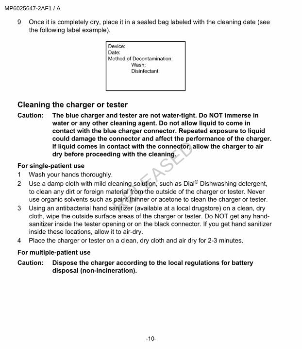
9 Once it is completely dry, place it in a sealed bag labeled with the cleaning date (seethe following label example).
Device:Date:Method of Decontamination: Wash: Disinfectant:
Cleaning the charger or testerCaution: The blue charger and tester are not water-tight. Do NOT immerse in
water or any other cleaning agent. Do not allow liquid to come incontact with the blue charger connector. Repeated exposure to liquidcould damage the connector and affect the performance of the charger.If liquid comes in contact with the connector, allow the charger to airdry before proceeding with the cleaning.
For single-patient use1 Wash your hands thoroughly.2 Use a damp cloth with mild cleaning solution, such as Dial® Dishwashing detergent,
to clean any dirt or foreign material from the outside of the charger or tester. Neveruse organic solvents such as paint thinner or acetone to clean the charger or tester.
3 Using an antibacterial hand sanitizer (available at a local drugstore) on a clean, drycloth, wipe the outside surface areas of the charger or tester. Do NOT get any hand-sanitizer inside the tester opening or on the black connector. If you get hand sanitizerinside these locations, allow it to air-dry.
4 Place the charger or tester on a clean, dry cloth and air dry for 2-3 minutes.
For multiple-patient useCaution: Dispose the charger according to the local regulations for battery
disposal (non-incineration).
-10-
MP6025647-2AF1 / A
RELEASED
Warning: Always clean the transmitter after removing it from the patient andbefore attaching it to the charger. If blood comes in contact withany surface areas of the charger or tester, the contaminated devicemust be discarded. The charger contains a battery which mayexplode upon incineration.
Follow this procedure to clean the charger or tester after each patient use:1 Wash your hands thoroughly.2 Use a damp cloth with mild cleaning solution, such as Dial Dishwashing
detergent, to clean any dirt or foreign material from the outside of the charger ortester. Never use organic solvents such as paint thinner or acetone to clean thecharger or tester.
3 Apply three to four drops of a quaternary ammonium compound disinfectant (forexample, Cavicide) on a clean, dry cloth and wipe all the surface areas of thecharger or tester.
4 Slightly dampen a clean cloth with isopropyl alcohol and wipe all the surfaceareas of the charger or tester.
5 Place the charger or tester on a clean dry, non-shedding cloth and allow to airdry.
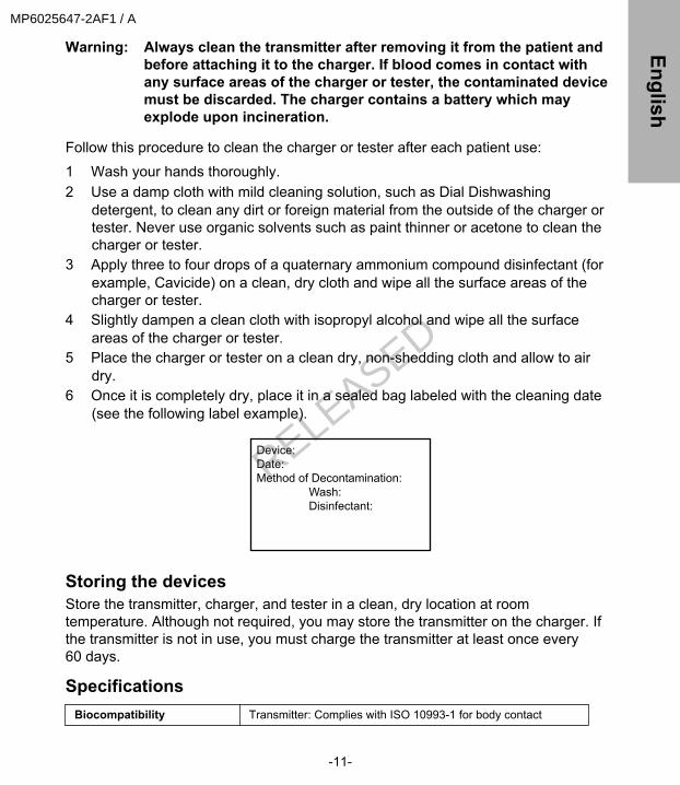
6 Once it is completely dry, place it in a sealed bag labeled with the cleaning date(see the following label example).
Device:Date:Method of Decontamination: Wash: Disinfectant:
Storing the devicesStore the transmitter, charger, and tester in a clean, dry location at roomtemperature. Although not required, you may store the transmitter on the charger. Ifthe transmitter is not in use, you must charge the transmitter at least once every60 days.
SpecificationsBiocompatibility Transmitter: Complies with ISO 10993-1 for body contact
-11-
EnglishMP6025647-2AF1 / A
RELEASED
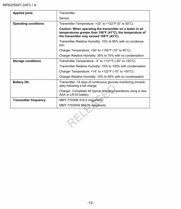
Applied parts Transmitter
Sensor
Operating conditions Transmitter Temperature: +32° to +122°F (0° to 50°C)
Caution: When operating the transmitter on a tester in airtemperatures greater than 106°F (41°C), the temperature ofthe transmitter may exceed 109°F (43°C).Transmitter Relative Humidity: 10% to 95% with no condensa-tion
Charger Temperature: +50° to +104°F (10° to 40°C)
Charger Relative Humidity: 30% to 75% with no condensation
Storage conditions Transmitter Temperature: -4° to +131°F (-20° to +55°C)
Transmitter Relative Humidity: 10% to 100% with condensation
Charger Temperature: +14° to +122°F (-10° to +50°C)
Charger Relative Humidity: 10% to 95% with no condensation
Battery life Transmitter: 14 days of continuous glucose monitoring immedi-ately following a full charge
Charger: Completes 40 typical charging operations using a newAAA or LR-03 battery
Transmitter frequency MMT-7703NA 916.5 megahertz
MMT-7703WW 868.35 megahertz
-12-
MP6025647-2AF1 / A
RELEASED
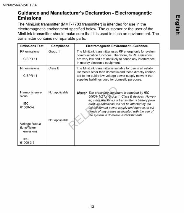
Guidance and Manufacturer's Declaration - ElectromagneticEmissionsThe MiniLink transmitter (MMT-7703 transmitter) is intended for use in theelectromagnetic environment specified below. The customer or the user of theMiniLink transmitter should make sure that it is used in such an environment. Thetransmitter contains no reparable parts.
Emissions Test Compliance Electromagnetic Environment - Guidance
RF emissions CISPR 11
Group 1 The MiniLink transmitter uses RF energy only for systemcommunication functions. Therefore, its RF emissionsare very low and are not likely to cause any interferencein nearby electronic equipment.
RF emissions CISPR 11
Harmonic emis-sions IEC61000-3-2
Voltage fluctua-tions/flicker emissions IEC61000-3-3
Class B
Not applicable
Not applicable
The MiniLink transmitter is suitable for use in all estab-lishments other than domestic and those directly connec-ted to the public low-voltage power supply network thatsupplies buildings used for domestic purposes.
Note: The preceding statement is required by IEC60601-1-2 for Group 1, Class B devices. Howev-er, since the MiniLink transmitter is battery pow-ered, its emissions will not be affected by theestablishment power supply and there is no evi-dence of any issues associated with the use ofthe system in domestic establishments.
-13-
EnglishMP6025647-2AF1 / A
RELEASED
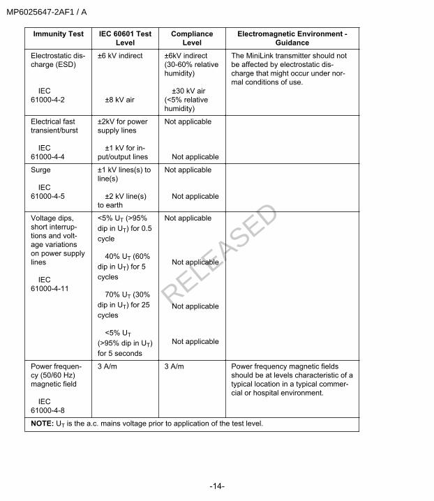
Immunity Test IEC 60601 TestLevel
ComplianceLevel
Electromagnetic Environment -Guidance
Electrostatic dis-charge (ESD) IEC61000-4-2
±6 kV indirect ±8 kV air
±6kV indirect(30-60% relativehumidity) ±30 kV air(<5% relativehumidity)
The MiniLink transmitter should notbe affected by electrostatic dis-charge that might occur under nor-mal conditions of use.
Electrical fasttransient/burst IEC61000-4-4
±2kV for powersupply lines ±1 kV for in-put/output lines
Not applicable Not applicable
Surge IEC61000-4-5
±1 kV lines(s) toline(s) ±2 kV line(s)to earth
Not applicable Not applicable
Voltage dips,short interrup-tions and volt-age variationson power supplylines IEC61000-4-11
<5% UT (>95%dip in UT) for 0.5cycle 40% UT (60%dip in UT) for 5cycles 70% UT (30%dip in UT) for 25cycles <5% UT(>95% dip in UT)for 5 seconds
Not applicable Not applicable Not applicable Not applicable
Power frequen-cy (50/60 Hz)magnetic field IEC61000-4-8
3 A/m 3 A/m Power frequency magnetic fieldsshould be at levels characteristic of atypical location in a typical commer-cial or hospital environment.
NOTE: UT is the a.c. mains voltage prior to application of the test level.
-14-
MP6025647-2AF1 / A
RELEASED

Immunity Test IEC 60601 TestLevel
ComplianceLevel
Electromagnetic Environment -Guidance
Radiated RF IEC61000-4-3
3V/m 80MHz to2.5GHz
3V/m Portable and mobile RF communica-tions equipment should be used nocloser to any part of the MiniLinktransmitter, including cables, thanthe recommended separation dis-tance calculated from the equationapplicable to the frequency of thetransmitter. Recommended separation dis-tance: d=1.2√P 80MHz to 800 MHzd=2.3√P 800MHz to 2.5 GHz Where P is the maximum outputpower rating of the transmitter inwatts (W) according to the transmit-ter manufacturer and d is the recom-mended separation distance inmeters (m). Field strengths from fixed RFtransmitters, as determined by anelectromagnetic site surveya, shouldbe less than the compliance level ineach frequency range. Interferencemay occur in the vicinity of equip-ment marked with the following sym-bol:
-15-
EnglishMP6025647-2AF1 / A
RELEASED
Immunity Test IEC 60601 TestLevel
ComplianceLevel
Electromagnetic Environment -Guidance
NOTE: At 80 MHz and 800 MHz, the higher frequency range applies. NOTE: These guidelines may not apply in all situations. Electromagnetic propagation is affectedby absorption and reflection from structures, objects and people. a Field strengths from fixed transmitters, such as base stations for radio (cellular/cordless) tele-phones and land mobile radios, amateur radio, AM and FM radio broadcasts and TV broadcastcannot be predicted theoretically with accuracy. To access the electromagnetic environment dueto fixed RF transmitters, an electromagnetic site survey should be considered. If the measuredfield strength in the location in which the MiniLink transmitter is used exceeds the applicable RFcompliance level above, the MiniLink transmitter should be observed to verify normal operation. Ifabnormal performance is observed, additional measures may be necessary, such as re-orientingor relocating the MiniLink transmitter.
-16-
MP6025647-2AF1 / A
RELEASED

Recommended separation distances between portable and mobile RF communicationsequipment and the MiniLink transmitter (MMT 7703 transmitter)
This section provides information on the recommended separation distance between portable andmobile RF communications equipment and the MiniLink transmitter. The MiniLink transmitter is in-tended for use in an electromagnetic environment in which radiated RF disturbances are control-led. The customer or the user of the MiniLink transmitter can help prevent electromagneticinterference by maintaining a minimum distance between portable and mobile RF communicationsequipment (transmitters) and the MiniLink transmitter as recommended below, according to themaximum output power of the communications equipment.
Rated maximum outputpower of transmitter (W)
Separation distance according to the frequency of transmit-ter (m)
80MHz to 800MHz d=1.2√P
800MHz to 2.5GHz d=2.3√P
0.01 0.12 0.23
0.1 0.38 0.74
1 1.2 2.3
10 3.8 7.4
100 12 23
For transmitters rated at a maximum output power not listed above, the recommended separationdistance d in meters (m) can be estimated using the equation applicable to the frequency of thetransmitter, where p is the maximum output power rating of the transmitter in watts (W) accordingto the transmitter manufacturer.
NOTE: At 80 MHz and 800 MHz, the separation distance for the higher frequency range applies. NOTE: These guidelines may not apply in all situations. Electromagnetic propagation is affectedby absorption and reflection from structures, objects and people.
WarrantyMedtronic MiniMed warrants the Medtronic MiniLink transmitter to the purchaser ofthe product against defects in material and workmanship for a period of twelve (12)months and the charger for up to six (6) months from the date of purchase.During the warranty period, Medtronic MiniMed will repair or replace, at its discretion,any defective MiniLink transmitter or charger, subject to the conditions andexclusions stated herein. This warranty applies only to new devices. In the event aMiniLink transmitter or charger is repaired or replaced, the warranty period will not beextended past its original expiration date.This warranty is valid only if the Medtronic MiniLink transmitter or charger is used inaccordance with the manufacturer’s instructions. Without limitation, this warranty willnot apply:• If damage results from changes or modifications made to the MiniLink transmitter
or charger by the user, or third parties, after the date of sale;
-17-
EnglishMP6025647-2AF1 / A
RELEASED

• If service or repairs are performed by any person or entity other than themanufacturer;
• If damage results from a Force Majeur or other event beyond the control of themanufacturer;
• If damage results from negligence or improper use, including but not limited to:improper storage, submersion in fluid, physical abuse (such as dropping); or
• If blood or water has entered the inside of the MiniLink transmitter connector.This warranty shall be personal to the original user. Any sale, rental or other transfer oruse of the product covered by this warranty to or by a user other than the original usershall cause this warranty to immediately terminate. This warranty does not apply toGlucose Sensors and other accessories.The remedies provided for in this warranty are the exclusive remedies available for anydefects in material or workmanship in the product. Any statutory rights granted toconsumers under any applicable legislation are reserved. Neither Medtronic MiniMed norits suppliers or distributors shall be liable for any incidental, consequential, punitive orspecial damages of any nature or kind caused by or arising out of a defect in the product.All other warranties, except any applicable mandatory statutory warranties, expressed orimplied, are excluded and specifically disclaimed, including, but not limited to, anywarranty of merchantability or fitness for a particular purpose.
-18-
MP6025647-2AF1 / A
RELEASED
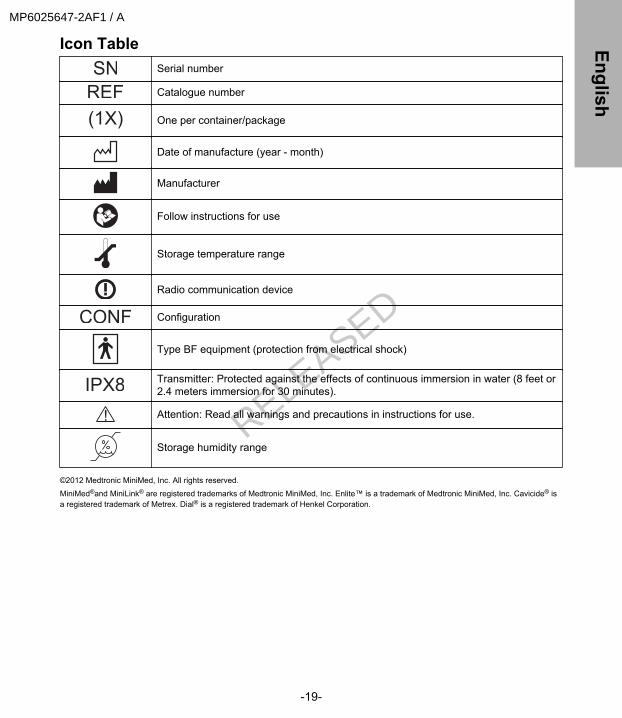
Icon TableSerial number
Catalogue number
(1X) One per container/package
Date of manufacture (year - month)
Manufacturer
Follow instructions for use
Storage temperature range
Radio communication device
Configuration
Type BF equipment (protection from electrical shock)
Transmitter: Protected against the effects of continuous immersion in water (8 feet or2.4 meters immersion for 30 minutes).
Attention: Read all warnings and precautions in instructions for use.
Storage humidity range
©2012 Medtronic MiniMed, Inc. All rights reserved.
MiniMed®and MiniLink® are registered trademarks of Medtronic MiniMed, Inc. Enlite™ is a trademark of Medtronic MiniMed, Inc. Cavicide® isa registered trademark of Metrex. Dial® is a registered trademark of Henkel Corporation.
-19-
EnglishMP6025647-2AF1 / A
RELEASED

-20-
MP6025647-2AF1 / A
RELEASED
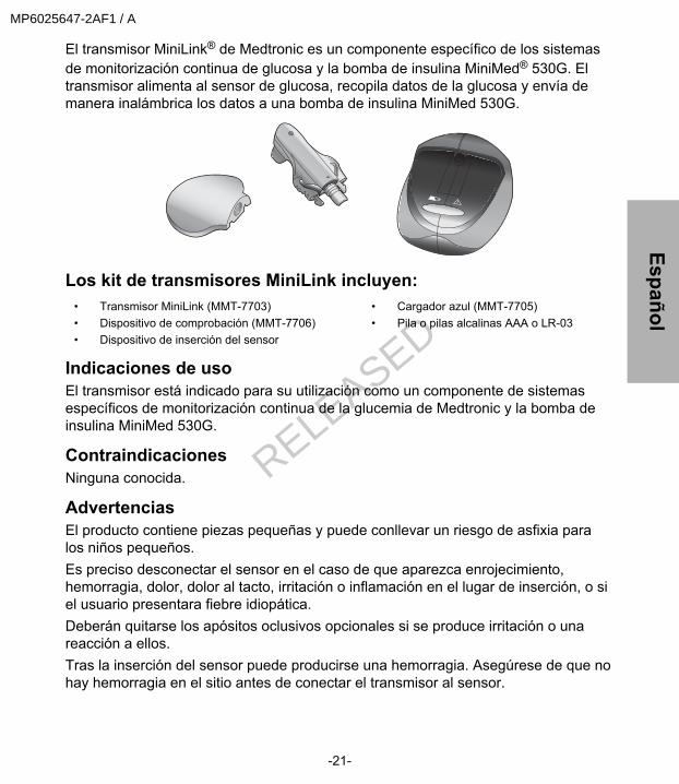
El transmisor MiniLink® de Medtronic es un componente específico de los sistemasde monitorización continua de glucosa y la bomba de insulina MiniMed® 530G. Eltransmisor alimenta al sensor de glucosa, recopila datos de la glucosa y envía demanera inalámbrica los datos a una bomba de insulina MiniMed 530G.
Los kit de transmisores MiniLink incluyen:• Transmisor MiniLink (MMT-7703)• Dispositivo de comprobación (MMT-7706)• Dispositivo de inserción del sensor
• Cargador azul (MMT-7705)• Pila o pilas alcalinas AAA o LR-03
Indicaciones de usoEl transmisor está indicado para su utilización como un componente de sistemasespecíficos de monitorización continua de la glucemia de Medtronic y la bomba deinsulina MiniMed 530G.
ContraindicacionesNinguna conocida.
AdvertenciasEl producto contiene piezas pequeñas y puede conllevar un riesgo de asfixia paralos niños pequeños.Es preciso desconectar el sensor en el caso de que aparezca enrojecimiento,hemorragia, dolor, dolor al tacto, irritación o inflamación en el lugar de inserción, o siel usuario presentara fiebre idiopática.Deberán quitarse los apósitos oclusivos opcionales si se produce irritación o unareacción a ellos.Tras la inserción del sensor puede producirse una hemorragia. Asegúrese de que nohay hemorragia en el sitio antes de conectar el transmisor al sensor.
-21-
EspañolMP6025647-2AF1 / A
RELEASED

• Si se produce alguna hemorragia, aplique una presión continua utilizando una gasaestéril o un paño limpio en la zona de inserción hasta que cese la hemorragia.Cuando se haya detenido la hemorragia, conecte el transmisor al sensor.
• Si la hemorragia persiste transcurridos tres minutos, retire el sensor y deséchelo.Inserte un nuevo sensor en una ubicación diferente.
Póngase en contacto con la línea de asistencia 24 horas si experimenta cualquiera delas reacciones adversas asociadas al transmisor o al sensor.
Campos magnéticosNo exponga el transmisor a equipos de MRI, dispositivos de diatermia u otrosdispositivos que generen campos magnéticos potentes. Si el transmisor se expone deforma accidental a un campo magnético intenso, deje de utilizarlo y póngase en contactocon la línea de asistencia 24 horas para obtener ayuda.
Radiografías y exploraciones por MRI y TCSi debe hacerse una radiografía, exploración por MRI o TC, o exponerse a otro tipo deradiación, quítese el sensor y el transmisor antes de entrar en una sala que contengacualquiera de estos equipos.En la tarjeta de emergencia puede encontrar información importante acerca de lossistemas de seguridad de los aeropuertos y el uso de la bomba de insulina a bordo de unavión. Cuando viaje, asegúrese de llevar la tarjeta de emergencia que se le hasuministrado.
Medidas preventivasEstablezca un esquema de rotación para elegir nuevas zonas para el sensor. Evite laszonas del cuerpo cubiertas por ropa ceñida, que tengan tejido cicatricial o esténsometidas a un gran movimiento durante el ejercicio.
AvisoEl dispositivo cumple la normativa de la Comisión Federal de Comunicaciones (FCC) delos Estados Unidos y otras normativas internacionales en lo que respecta a lacompatibilidad electromagnética.Este dispositivo cumple con la Parte 15 de la normativa de la FCC. Su funcionamientoestá sujeto a las dos condiciones siguientes: (1) este dispositivo no puede causar unainterferencia perjudicial para la salud y (2) este dispositivo aceptará cualquierinterferencia recibida, incluyendo interferencias que pudiesen causar un funcionamientono deseado.
-22-
MP6025647-2AF1 / A
RELEASED

El transmisor no interfiere con ninguna señal de radiofrecuencia transmitida porfuentes externas. Estas normativas de la Comisión Federal deComunicaciones (FCC) están diseñadas para proporcionar una protección razonablefrente a interferencias de radiofrecuencia excesivas y evitar un funcionamientono deseado del dispositivo debido a interferencias electromagnéticas no deseadas.Importante: Los cambios o modificaciones no aprobados expresamente por laparte responsable del cumplimiento podrían anular la autoridad del usuariopara utilizar el equipo.
Interferencias de RF generadas por otros dispositivosLos dispositivos electrónicos de uso habitual por los consumidores que transmitan enla misma banda de frecuencia que utiliza el transmisor pueden impedir que eldispositivo receptor (bomba de insulina MiniMed 530G) reciba la información sobre laglucosa enviada por el transmisor. La mayoría de los teléfonos móviles (celulares) yde los teléfonos inalámbricos de 900 MHz, cuando transmiten o reciben, puedencausar una interrupción importante de la comunicación entre el transmisor y elreceptor. Es probable que otros dispositivos que operen en intervalos de frecuenciasimilares tengan un efecto similar. Sin embargo, esta interferencia no hará quese envíen datos incorrectos ni causará daños al transmisor.Las bombas de insulina MiniMed 530G incluyen una alerta "Señal débil" programableque le avisa cuando el dispositivo receptor no recibe conforme a lo previsto una omás transmisiones del transmisor. (El dispositivo receptor también emitirá una alerta"Sensor perdido" si se interrumpe la comunicación durante aproximadamente40 minutos).Los problemas de comunicación pueden resolverse habitualmente asegurándosede que la distancia entre el transmisor y el receptor sea inferior a 1,8 metros (6 pies),así como apagando o alejando otros dispositivos transmisores de RF. Tambiénpuede cambiar la orientación o la ubicación del transmisor, del receptor o de ambospara intentar corregir la interferencia. Las pruebas realizadas con diversos teléfonosmóviles (celulares) diferentes indican que la interferencia no supondrá un problemasi el teléfono está a una distancia de al menos 31 cm (12 pulgadas) del dispositivotransmisor o receptor durante su utilización (puede requerirse una distancia deseparación mayor para ciertos dispositivos).
Asistencia técnicaMedtronic MiniMed le ofrece una línea de asistencia 24 horas al día. En la línea deasistencia le atenderán representantes con formación en la configuración y elfuncionamiento del sistema de monitorización continua de glucosa. Cuando llame a
-23-
EspañolMP6025647-2AF1 / A
RELEASED
la línea de asistencia, tenga a mano el número de serie de la bomba. Puede encontrar elnúmero de serie de la bomba, así como el número telefónico de la línea de asistencia24 horas, en la parte trasera del dispositivo.
Departamento Número de teléfonoLínea de asistencia 24 horas (llamadas desde dentro de los Esta-dos Unidos)
800 646 4633
Línea de asistencia 24 horas (llamadas desde fuera de los Esta-dos Unidos)
+1 818 576 5555
Sitio web www.medtronicdiabetes.com
CargadorEl transmisor contiene una batería recargable no sustituible que puede recargarse con elcargador cuando sea necesario. El cargador dispone de un indicador luminoso verde quemuestra el estado de la carga y uno rojo que informa acerca de los problemas quepudieran ocurrir durante el periodo de carga. Si el indicador luminoso rojo se ilumina,consulte la sección Resolución de problemas. El cargador funciona con una pilaalcalina AAA, de tamaño E92 y tipo LR03 (se recomienda la marca Energizer).
Nota: Una pila AAA o LR-03 nueva contiene suficiente energía para recargar eltransmisor más de 40 veces. Si se instala la pila de forma incorrecta o la pila tieneun nivel bajo de carga, el cargador no funcionará. Repita los pasos de instalaciónde la pila utilizando una pila nueva.
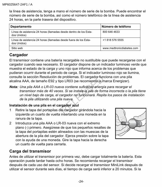
Instalación de una pila en el cargador azul1 Retire la tapa del portapilas del cargador girándola hacia la
izquierda un cuarto de vuelta insertando una moneda en laranura de la tapa.
2 Introduzca una pila AAA o LR-03 nueva con el extremoplano (-) primero. Asegúrese de que los pequeños resaltes dela tapa del portapilas estén alineados con las muescas de laabertura de la pila del cargador. Ejerza presión sobre la tapacon la ayuda de una moneda. Gire la tapa hacia la derechaun cuarto de vuelta para cerrarla.
Carga del transmisorAntes de utilizar el transmisor por primera vez, debe cargar totalmente la batería. Estaoperación puede tardar hasta ocho horas. Se recomienda recargar el transmisordespués de cada uso del sensor. Si decide recargar el transmisor MiniLink después deutilizar el sensor durante seis días, el tiempo de carga será inferior a 20 minutos. Si la
-24-
MP6025647-2AF1 / A
RELEASED
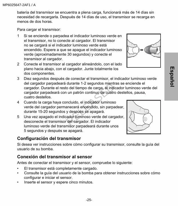
batería del transmisor se encuentra a plena carga, funcionará más de 14 días sinnecesidad de recargarla. Después de 14 días de uso, el transmisor se recarga enmenos de dos horas. Para cargar el transmisor:1 Si se enciende o parpadea el indicador luminoso verde en
el transmisor, no lo conecte al cargador. El transmisorno se cargará si el indicador luminoso verde estáencendido. Espere a que se apague el indicador luminosoverde (aproximadamente 30 segundos) y conecte eltransmisor al cargador.
2 Conecte el transmisor al cargador alineándolo, con el ladoplano hacia abajo, con el cargador. Junte totalmente losdos componentes.
3 Diez segundos después de conectar el transmisor, el indicador luminoso verdedel cargador parpadeará durante 1-2 segundos mientras se enciende elcargador. Durante el resto del tiempo de carga, el indicador luminoso verde delcargador parpadeará con un patrón continuo de cuatro destellos, pausa,cuatro destellos.
4 Cuando la carga haya concluido, el indicador luminosoverde del cargador permanecerá encendido, sin parpadear,durante 15-20 segundos y después se apagará.
5 Una vez apagado el indicador luminoso verde del cargador,desconecte el transmisor del cargador. El indicadorluminoso verde del transmisor parpadeará durante unos5 segundos y después se apagará.
Configuración del transmisorSi desea ver instrucciones sobre cómo configurar su transmisor, consulte la guía delusuario de su bomba.
Conexión del transmisor al sensorAntes de conectar el transmisor y el sensor, compruebe lo siguiente:• El transmisor está completamente cargado.• Consulte la guía del usuario de la bomba para obtener instrucciones sobre cómo
configurar e iniciar el sensor.• Inserte el sensor y espere cinco minutos.
-25-
EspañolMP6025647-2AF1 / A
RELEASED
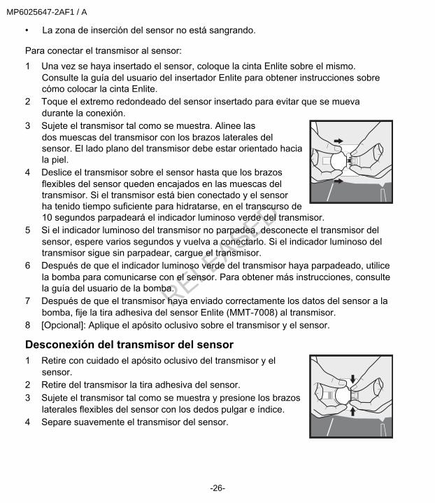
• La zona de inserción del sensor no está sangrando. Para conectar el transmisor al sensor:1 Una vez se haya insertado el sensor, coloque la cinta Enlite sobre el mismo.
Consulte la guía del usuario del insertador Enlite para obtener instrucciones sobrecómo colocar la cinta Enlite.
2 Toque el extremo redondeado del sensor insertado para evitar que se muevadurante la conexión.
3 Sujete el transmisor tal como se muestra. Alinee lasdos muescas del transmisor con los brazos laterales delsensor. El lado plano del transmisor debe estar orientado haciala piel.
4 Deslice el transmisor sobre el sensor hasta que los brazosflexibles del sensor queden encajados en las muescas deltransmisor. Si el transmisor está bien conectado y el sensorha tenido tiempo suficiente para hidratarse, en el transcurso de10 segundos parpadeará el indicador luminoso verde del transmisor.
5 Si el indicador luminoso del transmisor no parpadea, desconecte el transmisor delsensor, espere varios segundos y vuelva a conectarlo. Si el indicador luminoso deltransmisor sigue sin parpadear, cargue el transmisor.
6 Después de que el indicador luminoso verde del transmisor haya parpadeado, utilicela bomba para comunicarse con el sensor. Para obtener más instrucciones, consultela guía del usuario de la bomba.
7 Después de que el transmisor haya enviado correctamente los datos del sensor a labomba, fije la tira adhesiva del sensor Enlite (MMT-7008) al transmisor.
8 [Opcional]: Aplique el apósito oclusivo sobre el transmisor y el sensor.
Desconexión del transmisor del sensor1 Retire con cuidado el apósito oclusivo del transmisor y el
sensor.2 Retire del transmisor la tira adhesiva del sensor.3 Sujete el transmisor tal como se muestra y presione los brazos
laterales flexibles del sensor con los dedos pulgar e índice.4 Separe suavemente el transmisor del sensor.
-26-
MP6025647-2AF1 / A
RELEASED
Bañarse y nadarUna vez que el transmisor y el sensor estén conectados, formarán un sello herméticoa una profundidad de 2,4 m (8 pies) durante un máximo de 30 minutos. Puededucharse y nadar sin necesidad de quitárselos. No se necesita un apósito oclusivo.
Dispositivo de comprobaciónEl dispositivo de comprobación se utiliza para evaluar el transmisor y asegurarsede que funciona.
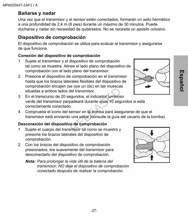
Conexión del dispositivo de comprobación1 Sujete el transmisor y el dispositivo de comprobación
tal como se muestra. Alinee el lado plano del dispositivo decomprobación con el lado plano del transmisor.
2 Presione el dispositivo de comprobación en el transmisorhasta que los brazos laterales flexibles del dispositivo decomprobación encajen (se oye un clic) en las muescassituadas a ambos lados del transmisor.
3 En el transcurso de 20 segundos, el indicador luminosoverde del transmisor parpadeará durante unos 10 segundos si estácorrectamente conectado.
4 Compruebe el icono del sensor en la bomba para asegurarse de que eltransmisor está enviando una señal (consulte la guía del usuario de la bomba).
Desconexión del dispositivo de comprobación1 Sujete el cuerpo del transmisor tal como se muestra y
presione los brazos laterales del dispositivo decomprobación.
2 Con los brazos del dispositivo de comprobaciónpresionados, tire suavemente del transmisor paradesconectarlo del dispositivo de comprobación.
Nota: Para prolongar la vida útil de la batería deltransmisor, NO deje el dispositivo de comprobaciónconectado después de realizar la comprobación.
-27-
EspañolMP6025647-2AF1 / A
RELEASED
Resolución de problemasPregunta: ¿Por qué parpadea rápidamente el indicador luminoso rojo del cargador?
aprox. 2 s aprox. 2 s aprox. 2 s
Respuesta: La carga de la batería del transmisor está muy baja. Deje el transmisor en elcargador durante 8 horas para que se recargue por completo. Si el indicador luminosorojo sigue parpadeando después de 8 horas, deje el transmisor en el cargador durante24 horas. Si el indicador luminoso rojo sigue parpadeando después de una cargacontinua durante 24 horas, llame a la línea de asistencia. Es posible que sea necesariosustituir el transmisor.Pregunta: ¿Por qué deja de parpadear el indicador luminoso verde y comienzaa parpadear el indicador rojo, con destellos más largos, durante el periodo de carga?
aprox. 2 s aprox. 2 s aprox. 2 s
Respuesta: La carga de la pila del cargador está baja. Asegúrese de que el transmisorno está conectado al cargador y sustituya la pila del cargador por una pila AAA o LR-03nueva.Pregunta: ¿Por qué parpadea en intervalos cortos y largos el indicador luminoso rojo delcargador?
aprox.1 s
aprox.1 s
aprox. 2 s aprox.1 s
aprox.1 s
Respuesta: La carga de la batería del transmisor Y de la pila del cargador está muybaja. Sustituya la pila AAA o LR-03 del cargador. Si observa el patrón de carga muy bajade la batería del transmisor, deje el transmisor en el cargador durante 8 horas pararecargarlo. Si el indicador luminoso rojo sigue parpadeando después de 8 horas, deje eltransmisor en el cargador durante 24 horas. Si el indicador luminoso rojo sigueparpadeando después de una carga continua durante 24 horas, llame a la línea deasistencia. Es posible que sea necesario sustituir el transmisor.
-28-
MP6025647-2AF1 / A
RELEASED
Pregunta: He dejado el transmisor en el cargador durante todo un día. ¿Causaráello algún daño al transmisor?Respuesta: El transmisor no sufrirá ningún daño. No se puede sobrecargar.Pregunta: ¿Qué he de hacer si el indicador luminoso verde del transmisorno parpadea una vez conectado al sensor?Respuesta: ¿Está el sensor insertado en el cuerpo? Si no está insertado, elindicador luminoso verde del transmisor no parpadeará ni el transmisor transmitiráseñales a la bomba de insulina.Si el sensor está insertado en el cuerpo, necesitará desconectar el transmisor delsensor, esperar varios segundos y volver a conectar. Si el indicador luminoso verdeno parpadea, cargue el transmisor.Pregunta: ¿Por qué no he visto parpadear el indicador luminoso verde deltransmisor después de conectarlo al dispositivo de comprobación?Respuesta: Compruebe la conexión. Si aún no ve parpadear el indicador luminosoverde, recargue por completo la batería del transmisor. Compruebe el transmisor conel dispositivo de comprobación. Si el indicador luminoso verde sigue sin parpadear,llame a la línea de asistencia. Es posible que sea necesario sustituir el transmisor.
Limpieza del transmisorPrecaución: No deseche el transmisor en un contenedor de residuos médicos
o en otro tipo de contenedor que se vaya a incinerar. Eltransmisor contiene una batería que puede explotar si se incinera.
Precaución: El cargador y el dispositivo de comprobación NO sonimpermeables. NO los sumerja en agua ni en ningún otroproducto de limpieza. Si entra líquido en el conector negro deldispositivo de comprobación, agítelo para eliminar el líquido ydéjelo secar al aire.
Para uso en un solo paciente1 Lávese bien las manos.2 Conecte el dispositivo de comprobación al transmisor.3 Humedezca un paño limpio con jabón líquido suave y agua templada. Limpie el
exterior del transmisor.4 Enjuague el transmisor con agua corriente templada.5 Utilizando un desinfectante antibacteriano (disponible en droguerías y
farmacias), limpie la superficie del transmisor con un paño limpio y seco.NO permita la entrada del desinfectante en la abertura del dispositivo de
-29-
EspañolMP6025647-2AF1 / A
RELEASED
comprobación o el conector del transmisor. La exposición repetida al desinfectantepodría dañar los conectores y afectar al funcionamiento del transmisor. Si entradesinfectante en el dispositivo de comprobación o el conector, déjelo secar al aire.
6 Desconecte el dispositivo de comprobación del transmisor.7 Coloque el transmisor sobre un paño limpio y seco y déjelo secar al aire durante
2-3 minutos.
Para uso en más de un pacientePrecaución: El cargador y el dispositivo de comprobación NO son impermeables.
NO los sumerja en agua ni en ningún otro producto de limpieza. Sientra líquido en el conector negro del dispositivo de comprobación,agítelo para eliminar el líquido y déjelo secar al aire.
Advertencia: Limpie siempre el transmisor después de retirarlo del paciente yantes de conectarlo al cargador. Si hay sangre en el interior delconector, debe desecharse el transmisor.Deseche el transmisor de acuerdo con la normativa local para laeliminación de baterías (sin incineración).
Siga este procedimiento para limpiar el transmisor tras su uso con cada paciente:1 Lávese bien las manos.2 Conecte el dispositivo de comprobación al transmisor.3 Humedezca un paño limpio con jabón líquido suave y agua templada. Limpie el
exterior del transmisor.4 Enjuague el transmisor con agua corriente templada.5 Ponga 3-4 gotas de un desinfectante compuesto de amonio cuaternario (por
ejemplo, Cavicide®) en un paño limpio y seco, y limpie el transmisor.6 Sujete el transmisor y límpielo con alcohol isopropílico al 70%.7 Desconecte el dispositivo de comprobación del transmisor.8 Coloque el transmisor sobre un paño limpio y seco que no desprenda pelusa y déjelo
secar al aire.
-30-
MP6025647-2AF1 / A
RELEASED
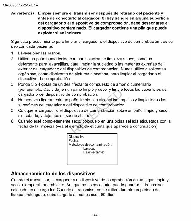
9 Cuando esté completamente seco, colóquelo en una bolsa sellada etiquetadacon la fecha de la limpieza (vea el ejemplo de etiqueta que aparecea continuación).
Dispositivo:Fecha:Método de descontaminación:
Lavado:Desinfectante:
Limpieza del cargador o el dispositivo de comprobaciónPrecaución: El cargador azul y el dispositivo de prueba no son herméticos.
NO los sumerja en agua ni en ningún otro producto de limpieza.No deje que el conector del cargador azul se moje. Unaexposición repetida a líquidos podría dañar el conector y afectaral rendimiento del cargador. Si el conector se moja, deje que elcargador se seque al aire antes de continuar con la limpieza.
Para uso en un solo paciente1 Lávese bien las manos.2 Utilice un paño humedecido con una solución de limpieza suave, como un
detergente para lavar la vajilla (por ejemplo, Dial®) para limpiar la suciedad o lasmaterias extrañas del exterior del cargador o del dispositivo de comprobación.Nunca utilice disolventes orgánicos, como disolvente de pinturas o acetona, paralimpiar el cargador o el dispositivo de comprobación.
3 Utilizando un desinfectante antibacteriano (disponible en droguerías yfarmacias), limpie la superficie exterior del cargador o del dispositivo decomprobación con un paño limpio y seco. NO permita la entrada deldesinfectante en la abertura del dispositivo de comprobación o en el conectornegro. Si entra desinfectante en estos lugares, déjelos secar al aire.
4 Coloque el cargador o el dispositivo de comprobación sobre un paño limpio yseco, y déjelo secar al aire durante 2-3 minutos.
Para uso en más de un pacientePrecaución: Deseche el cargador de acuerdo con la normativa local para la
eliminación de baterías (sin incineración).
-31-
EspañolMP6025647-2AF1 / A
RELEASED
Advertencia: Limpie siempre el transmisor después de retirarlo del paciente yantes de conectarlo al cargador. Si hay sangre en alguna superficiedel cargador o el dispositivo de comprobación, debe desecharse eldispositivo contaminado. El cargador contiene una pila que puedeexplotar si se incinera.
Siga este procedimiento para limpiar el cargador o el dispositivo de comprobación tras suuso con cada paciente:1 Lávese bien las manos.2 Utilice un paño humedecido con una solución de limpieza suave, como un
detergente para lavavajillas, para limpiar la suciedad o las materias extrañas delexterior del cargador o del dispositivo de comprobación. Nunca utilice disolventesorgánicos, como disolvente de pinturas o acetona, para limpiar el cargador o eldispositivo de comprobación.
3 Ponga 3 ó 4 gotas de un desinfectante compuesto de amonio cuaternario(por ejemplo, Cavicide) en un paño limpio y seco, y limpie todas las superficies delcargador o del dispositivo de comprobación.
4 Humedezca ligeramente un paño limpio con alcohol isopropílico y limpie todas lassuperficies del cargador o del dispositivo de comprobación.
5 Coloque el cargador o el dispositivo de comprobación sobre un paño limpio y seco,sin cubrirlo, y deje que se seque al aire.
6 Cuando esté completamente seco, colóquelo en una bolsa sellada etiquetada con lafecha de la limpieza (vea el ejemplo de etiqueta que aparece a continuación).
Dispositivo:Fecha:Método de descontaminación:
Lavado:Desinfectante:
Almacenamiento de los dispositivosGuarde el transmisor, el cargador y el dispositivo de comprobación en un lugar limpio yseco a temperatura ambiente. Aunque no es necesario, puede guardar el transmisorcolocado en el cargador. Cuando el transmisor no se utilice durante un periodo detiempo prolongado, debe cargarlo al menos cada 60 días.
-32-
MP6025647-2AF1 / A
RELEASED

EspecificacionesBiocompatibilidad Transmisor: Cumple la norma ISO 10993-1 para contacto cor-
poral
Partes aplicadas Transmisor
Sensor
Condiciones de funciona-miento
Temperatura del transmisor: 0 °C a 50 °C (+32 °F a +122 °F)
Precaución: Cuando se utiliza el transmisor en un disposi-tivo de comprobación a temperaturas atmosféricas supe-riores a 41 °C (106 °F), la temperatura del transmisor puedesuperar los 43 °C (109 °F).Humedad relativa del transmisor: 10% a 95% sin condensación
Temperatura del cargador: 10 °C a 40 °C (+50 °F a +104 °F)
Humedad relativa del cargador: 30% a 75% sin condensación
Condiciones de almacena-miento
Temperatura del transmisor: -20 °C a +55 °C (-4 °F a +131 °F)
Humedad relativa del transmisor: 10% a 100% con condensa-ción
Temperatura del cargador: -10 °C a +50 °C (+14 °F a +122 °F)
Humedad relativa del cargador: 10% a 95% sin condensación
Vida útil de la batería/pila Transmisor: 14 días de monitorización continua de glucosa in-mediatamente después de una carga completa
Cargador: realiza 40 operaciones típicas de carga con una pi-la AAA o LR-03 nueva
Frecuencia del transmisor MMT-7703NA 916,5 MHz
MMT-7703WW 868,35 MHz
-33-
EspañolMP6025647-2AF1 / A
RELEASED
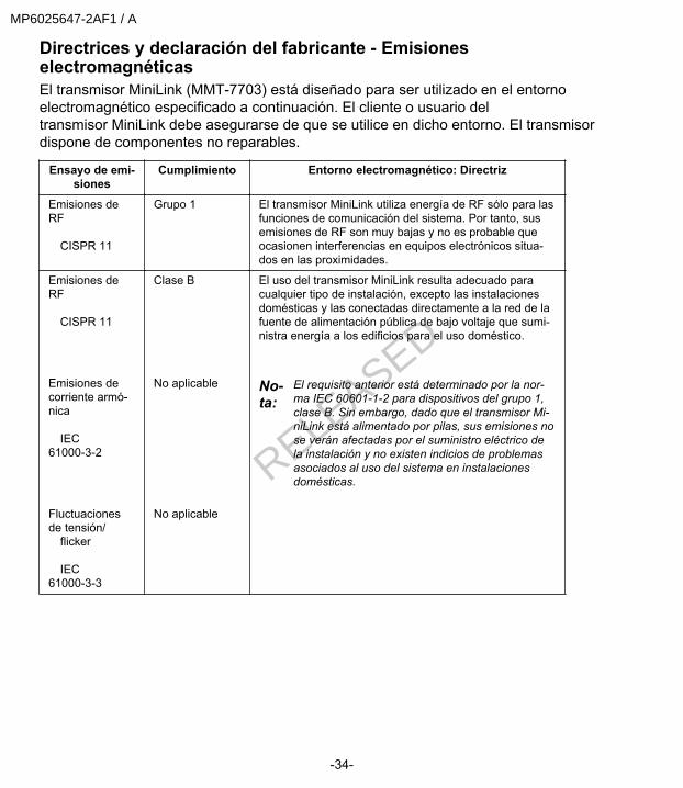
Directrices y declaración del fabricante - EmisioneselectromagnéticasEl transmisor MiniLink (MMT-7703) está diseñado para ser utilizado en el entornoelectromagnético especificado a continuación. El cliente o usuario deltransmisor MiniLink debe asegurarse de que se utilice en dicho entorno. El transmisordispone de componentes no reparables.
Ensayo de emi-siones
Cumplimiento Entorno electromagnético: Directriz
Emisiones deRF CISPR 11
Grupo 1 El transmisor MiniLink utiliza energía de RF sólo para lasfunciones de comunicación del sistema. Por tanto, susemisiones de RF son muy bajas y no es probable queocasionen interferencias en equipos electrónicos situa-dos en las proximidades.
Emisiones deRF CISPR 11
Emisiones decorriente armó-nica IEC61000-3-2
Fluctuacionesde tensión/ flicker IEC61000-3-3
Clase B
No aplicable
No aplicable
El uso del transmisor MiniLink resulta adecuado paracualquier tipo de instalación, excepto las instalacionesdomésticas y las conectadas directamente a la red de lafuente de alimentación pública de bajo voltaje que sumi-nistra energía a los edificios para el uso doméstico.
No-ta:
El requisito anterior está determinado por la nor-ma IEC 60601-1-2 para dispositivos del grupo 1,clase B. Sin embargo, dado que el transmisor Mi-niLink está alimentado por pilas, sus emisiones nose verán afectadas por el suministro eléctrico dela instalación y no existen indicios de problemasasociados al uso del sistema en instalacionesdomésticas.
-34-
MP6025647-2AF1 / A
RELEASED
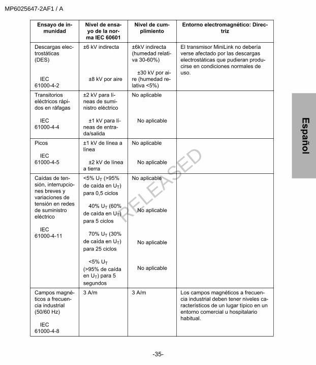
Ensayo de in-munidad
Nivel de ensa-yo de la nor-ma IEC 60601
Nivel de cum-plimiento
Entorno electromagnético: Direc-triz
Descargas elec-trostáticas(DES) IEC61000-4-2
±6 kV indirecta ±8 kV por aire
±6kV indirecta(humedad relati-va 30-60%) ±30 kV por ai-re (humedad re-lativa <5%)
El transmisor MiniLink no deberíaverse afectado por las descargaselectrostáticas que pudieran produ-cirse en condiciones normales deuso.
Transitorioseléctricos rápi-dos en ráfagas IEC61000-4-4
±2 kV para lí-neas de sumi-nistro eléctrico ±1 kV para lí-neas de entra-da/salida
No aplicable No aplicable
Picos IEC61000-4-5
±1 kV de línea alínea ±2 kV de líneaa tierra
No aplicable No aplicable
Caídas de ten-sión, interrupcio-nes breves yvariaciones detensión en redesde suministroeléctrico IEC61000-4-11
<5% UT (>95%de caída en UT)para 0,5 ciclos 40% UT (60%de caída en UT)para 5 ciclos 70% UT (30%de caída en UT)para 25 ciclos <5% UT(>95% de caídaen UT) para 5segundos
No aplicable No aplicable No aplicable No aplicable
Campos magné-ticos a frecuen-cia industrial(50/60 Hz) IEC61000-4-8
3 A/m 3 A/m Los campos magnéticos a frecuen-cia industrial deben tener niveles ca-racterísticos de un lugar típico en unentorno comercial u hospitalariohabitual.
-35-
EspañolMP6025647-2AF1 / A
RELEASED
NOTA: UT es la tensión de la red de corriente alterna antes de la aplicación del nivel de ensayo.
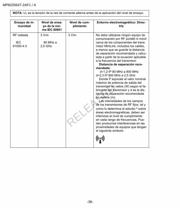
Ensayo de in-munidad
Nivel de ensa-yo de la nor-ma IEC 60601
Nivel de cum-plimiento
Entorno electromagnético: Direc-triz
RF radiada IEC61000-4-3
3 V/m 80 MHz a2,5 GHz
3 V/m No debe utilizarse ningún equipo decomunicación por RF portátil ni móvilcerca de los componentes del trans-misor MiniLink, incluidos los cables,a menos que se guarde la distanciade separación recomendada y calcu-lada a partir de la ecuación aplicablea la frecuencia del transmisor. Distancia de separación reco-mendada: d=1,2√P 80 MHz a 800 MHzd=2,3√P 800 MHz a 2,5 GHz Donde P equivale al valor nominalmáximo de potencia de salida deltransmisor en vatios (W) según el fa-bricante del transmisor y d es la dis-tancia de separación recomendadaen metros (m). Las intensidades de los camposde los transmisores de RF fijos, tal ycomo lo determina el estudio a sobreáreas electromagnéticas, deben serinferiores al nivel de cumplimientoen cada rango de frecuencias. Pue-den producirse interferencias en lasproximidades de equipos que tenganel siguiente símbolo:
-36-
MP6025647-2AF1 / A
RELEASED

Ensayo de in-munidad
Nivel de ensa-yo de la nor-ma IEC 60601
Nivel de cum-plimiento
Entorno electromagnético: Direc-triz
NOTA: A 80 MHz y 800 MHz se aplica el rango de frecuencias más alto. NOTA:Es posible que estas directrices no sean aplicables en todas las situaciones. La propa-gación electromagnética se ve afectada por la absorción y la reflexión producidas por estructuras,objetos y personas. aTeóricamente no es posible predecir con exactitud las intensidades de los campos de transmi-sores fijos, tales como estaciones de base para teléfonos por radiofrecuencia (móviles/celulares/inalámbricos) y radios móviles terrestres, aparatos de radioaficionado, emisiones de radio de AMy FM y emisiones de televisión. Para acceder al entorno electromagnético generado por los trans-misores de RF fijos, debe considerarse la posibilidad de realizar un estudio electromagnético dellugar. Si la intensidad de campo medida en la ubicación en la que se utiliza el transmisor MiniLinksupera el nivel de cumplimiento de la normativa sobre RF aplicable indicado anteriormente, sedeberá vigilar el transmisor MiniLink para comprobar si funciona correctamente. Si observa unfuncionamiento anormal, pueden ser necesarias medidas adicionales, como cambiar la orienta-ción o la posición del transmisor MiniLink.
-37-
EspañolMP6025647-2AF1 / A
RELEASED
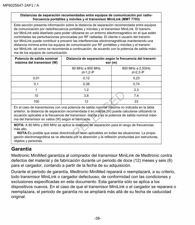
Distancias de separación recomendadas entre equipos de comunicación por radio-frecuencia portátiles y móviles y el transmisor MiniLink (MMT 7703)
Esta sección presenta información sobre la distancia de separación recomendada entre equiposde comunicación por radiofrecuencia portátiles y móviles y el transmisor MiniLink. El transmi-sor MiniLink está diseñado para poder utilizarse en un entorno electromagnético en el que esténcontroladas las perturbaciones provocadas por RF radiadas. El cliente o usuario del transmi-sor MiniLink puede contribuir a prevenir las interferencias electromagnéticas manteniendo unadistancia mínima entre los equipos de comunicación por RF portátiles y móviles y el transmi-sor MiniLink, tal como se recomienda a continuación, de acuerdo con la potencia de salida máxi-ma de los equipos de comunicación.
Potencia de salida nominalmáxima del transmisor (W)
Distancia de separación según la frecuencia del transmi-sor (m)
80 MHz a 800 MHz d=1,2√P
800 MHz a 2,5GHz d=2,3√P
0,01 0,12 0,23
0,1 0,38 0,74
1 1,2 2,3
10 3,8 7,4
100 12 23
En el caso de transmisores con una potencia de salida nominal máxima no indicada en la tablaanterior, la distancia de separación recomendada d en metros (m) puede calcularse utilizando laecuación aplicable a la frecuencia del transmisor, donde p es la potencia de salida nominal máxi-ma del transmisor en vatios (W) según el fabricante.
NOTA: A 80 MHz y 800 MHz se aplica la distancia de separación para el rango de frecuenciasmás alto. NOTA:Es posible que estas directrices no sean aplicables en todas las situaciones. La propa-gación electromagnética se ve afectada por la absorción y la reflexión producidas por estructuras,objetos y personas.
GarantíaMedtronic MiniMed garantiza al comprador del transmisor MiniLink de Medtronic contradefectos del material y de fabricación durante un periodo de doce (12) meses y seis (6)para el cargador, contando a partir de la fecha de su adquisición.Durante el periodo de garantía, Medtronic MiniMed reparará o reemplazará, a su criterio,todo transmisor MiniLink o cargador defectuoso, de conformidad con las condiciones yexclusiones especificadas en este documento. Esta garantía sólo se aplica a losdispositivos nuevos. En el caso de que el transmisor MiniLink o el cargador se reparara oreemplazara, el periodo de garantía no se ampliará más allá de su fecha de caducidadoriginal.
-38-
MP6025647-2AF1 / A
RELEASED

La presente garantía sólo es válida si el transmisor MiniLink o el cargador deMedtronic se utiliza de acuerdo con las instrucciones del fabricante. Esta garantíano se aplicará, sin excepción:• Si el daño se produce como resultado de modificaciones o cambios realizados
en el transmisor MiniLink o el cargador por parte del usuario o terceros despuésde la fecha de venta.
• Si el mantenimiento o las reparaciones son realizadas por cualquier persona oentidad que no sea el fabricante.
• Si el daño se produce como consecuencia de una causa de fuerza mayor u otrosuceso que escape al control del fabricante.
• Si el daño se produce como consecuencia de una negligencia o un usoincorrecto, incluidos entre otros los siguientes: almacenamiento incorrecto,inmersión en líquidos, maltrato (por ejemplo, si se cae); o bien
• Si ha entrado sangre o agua en el conector del transmisor MiniLink.Esta garantía se aplicará exclusivamente al usuario original. La garantía quedaráanulada de inmediato si hubiera existido cualquier tipo de venta, alquiler u otratransferencia o utilización diferente al establecido en esta garantía o por un usuarioajeno al usuario original. Esta garantía no se aplica a los sensores de glucosa yotros accesorios.Las soluciones proporcionadas en esta garantía son las únicas exclusivamentedisponibles en caso de defectos de material o fabricación del producto. Se reservantodos los derechos establecidos por la ley concecidos a los consumidores deconformidad con la legislación aplicable. Ni Medtronic MiniMed ni ninguno de susproveedores o distribuidores serán responsables de daños fortuitos, consecuentes,punitivos o especiales de ningún tipo que hayan sido provocados por un defecto enel producto.A excepción de las garantías estatutarias de carácter obligatorio, se excluyen yespecíficamente se rechazan el resto de garantías, expresas o implícitas, incluidas,entre otras, las garantías de comerciabilidad e idoneidad para un propósito concreto.
-39-
EspañolMP6025647-2AF1 / A
RELEASED
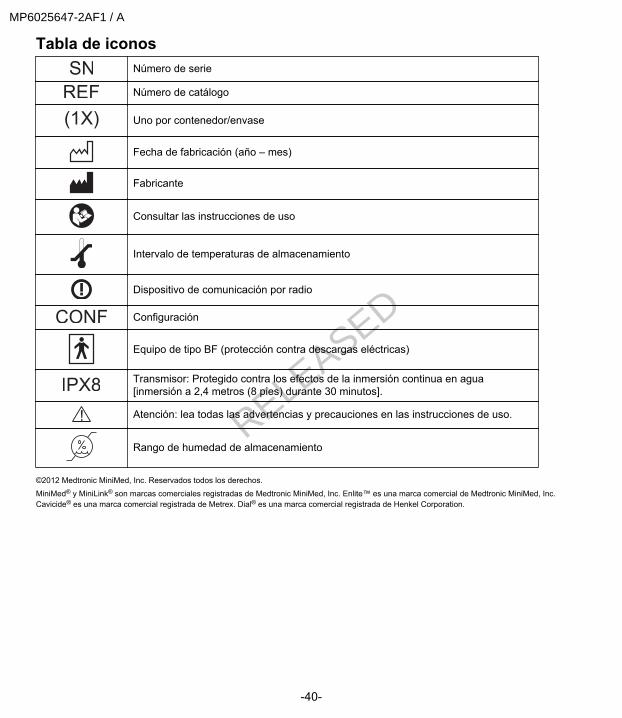
Tabla de iconosNúmero de serie
Número de catálogo
(1X) Uno por contenedor/envase
Fecha de fabricación (año – mes)
Fabricante
Consultar las instrucciones de uso
Intervalo de temperaturas de almacenamiento
Dispositivo de comunicación por radio
Configuración
Equipo de tipo BF (protección contra descargas eléctricas)
Transmisor: Protegido contra los efectos de la inmersión continua en agua[inmersión a 2,4 metros (8 pies) durante 30 minutos].
Atención: lea todas las advertencias y precauciones en las instrucciones de uso.
Rango de humedad de almacenamiento
©2012 Medtronic MiniMed, Inc. Reservados todos los derechos.
MiniMed® y MiniLink® son marcas comerciales registradas de Medtronic MiniMed, Inc. Enlite™ es una marca comercial de Medtronic MiniMed, Inc.Cavicide® es una marca comercial registrada de Metrex. Dial® es una marca comercial registrada de Henkel Corporation.
-40-
MP6025647-2AF1 / A
RELEASED

MP6025647-2AF1 / A
RELEASED

6025647-2AF1_a
REF MMT-7703 MMT-7705 MMT-7706
MP6025647-2AF1 / A
RELEASED