transport and main roads specifications mrts226
TRANSCRIPT
Technical Specification Transport and Main Roads Specifications MRTS226 Telecommunications Field Cabinets November 2020
Transport and Main Roads Specifications, November 2020
Copyright © The State of Queensland (Department of Transport and Main Roads) 2020. Licence
This work is licensed by the State of Queensland (Department of Transport and Main Roads) under a Creative Commons Attribution (CC BY) 4.0 International licence. CC BY licence summary statement In essence, you are free to copy, communicate and adapt this work, as long as you attribute the work to the State of Queensland (Department of Transport and Main Roads). To view a copy of this licence, visit: https://creativecommons.org/licenses/by/4.0/ Translating and interpreting assistance
The Queensland Government is committed to providing accessible services to Queenslanders from all cultural and linguistic backgrounds. If you have difficulty understanding this publication and need a translator, please call the Translating and Interpreting Service (TIS National) on 13 14 50 and ask them to telephone the Queensland Department of Transport and Main Roads on 13 74 68.
Disclaimer While every care has been taken in preparing this publication, the State of Queensland accepts no responsibility for decisions or actions taken as a result of any data, information, statement or advice, expressed or implied, contained within. To the best of our knowledge, the content was correct at the time of publishing. Feedback Please send your feedback regarding this document to: [email protected]
Transport and Main Roads Specifications, November 2020 i
Contents
1 Introduction ....................................................................................................................................1
2 Definition of terms .........................................................................................................................2
3 Referenced documents .................................................................................................................2
4 Quality system requirements .......................................................................................................4
4.1 Hold Points, Witness Points and Milestones .................................................................................. 4
5 Environmental conditions .............................................................................................................5
6 Design and manufacture ...............................................................................................................5
6.1 Materials ......................................................................................................................................... 5
6.2 Ventilation and cooling system ....................................................................................................... 6 6.2.1 General ...........................................................................................................................6 6.2.2 Equipment ......................................................................................................................6 6.2.3 Operation and performance ...........................................................................................7
6.3 Dimensions ..................................................................................................................................... 7
6.4 Access doors, gland plates and drain holes ................................................................................... 7 6.4.1 General ...........................................................................................................................7 6.4.2 Gland plates ...................................................................................................................8 6.4.3 Drain holes .....................................................................................................................8 6.4.4 Gaskets ..........................................................................................................................8 6.4.5 Door hinges and locks ....................................................................................................8
6.5 Installation of CyberLocks ............................................................................................................... 9
6.6 Programing CyberLocks ................................................................................................................. 9
6.7 Cyberkeys ....................................................................................................................................... 9 6.7.1 Document storage pocket ........................................................................................... 10
6.8 Equipment racks ........................................................................................................................... 10
6.9 Cable management ...................................................................................................................... 10
6.10 Danger sign ................................................................................................................................... 10
6.11 Surface finish ................................................................................................................................ 10
6.12 Mounting surface, facilities and structural integrity ....................................................................... 11 6.12.1 Lifting and transportation points .................................................................................. 11
7 Installation ................................................................................................................................... 12
8 Storage ......................................................................................................................................... 12
9 Electrical requirements .............................................................................................................. 12
9.1 Electrical safety ............................................................................................................................. 12
9.2 Power supply ................................................................................................................................ 12 9.2.1 Metering ....................................................................................................................... 12 9.2.2 Standby generator connection .................................................................................... 13
9.3 Switchboard .................................................................................................................................. 14
9.4 Arrangement of terminals ............................................................................................................. 14
9.5 Connection of equipment .............................................................................................................. 14 9.5.1 Power socket outlets ................................................................................................... 15 9.5.2 Hardwired equipment .................................................................................................. 15
9.6 Cabinet lighting ............................................................................................................................. 16
Transport and Main Roads Specifications, November 2020 ii
9.7 Radio frequency interference ........................................................................................................ 16
9.8 Protection against electrical transients and over-voltage ............................................................. 16 9.8.1 General ........................................................................................................................ 16 9.8.2 Surge filters ................................................................................................................. 17
10 Telecommunication requirements ............................................................................................ 17
10.1 Provision for connection to telecommunication lines .................................................................... 17
10.2 Telecommunications service ........................................................................................................ 17
11 Documentation ............................................................................................................................ 18
12 Guarantee / Warranty ................................................................................................................. 18
13 Spare components...................................................................................................................... 18
14 Packaging and shipping ............................................................................................................ 18
15 Non-conforming product ........................................................................................................... 19
16 Sample for evaluation ................................................................................................................ 19
17 Acceptance testing and certification ........................................................................................ 19
18 Program schedule....................................................................................................................... 19
19 Training ........................................................................................................................................ 19
Technical Specifications, MRTS226 Telecommunications Field Cabinets
Transport and Main Roads Specifications, November 2020 1
1 Introduction
This Technical Specification applies to the supply, manufacture and installation of field cabinets for housing roadside telecommunications and Intelligent Transport Systems (ITS) field equipment as an integral part of the Department of Transport and Main Roads' wider requirement for telecommunications systems.
The scope of this Technical Specification includes the following:
• supply and installation of metered and unmetered field cabinets that are plinth-mounted, pole mounted or top-mounted, to house roadside telecommunications field equipment
• supply and installation of plinths
• electrical switchboard and associated internal wiring
• cabinet ventilation / cooling system
• cabinet lighting
• provision and connection of mains power and telecommunications services to the cabinet, and
• supply and installation of double cabinet and associated plinths and accessories. A double cabinet has two vertical racking systems, two front doors and is about twice the width of a single cabinet.
The following items are excluded from the scope of this Technical Specification:
• wiring connections to field equipment housed within the cabinet, and
• connection to the Transport and Main Roads telecommunications network.
Mains power supplied to telecommunications field cabinets was, until recently, only unmetered. The deployment of ITS equipment with varying load meant that the existing unmetered tariffs may no longer be economical and, therefore, metered cabinets became a viable option.
In addition, in some districts, the electricity entities require that power connections to telecommunication field cabinets be metered in order to comply with their internal requirements, including requirements around connections to socket outlets; therefore, the decision to use a metered or unmetered cabinet depends on the specific issue raised and the decision is made by the Principal in conjunction with the electricity entity.
The decision to use plinth-mounted, pole mounted or top-mounted cabinet depends on the application and is made by the Project Principal.
This Technical Specification shall be read in conjunction with MRTS01 Introduction to Technical Specifications, MRTS50 Specific Quality System Requirements and other Technical Specifications as appropriate.
This Technical Specification forms part of the Transport and Main Roads Specifications Manual. All equipment and material, where not otherwise specified in this Technical Specification, shall be in accordance with the appropriate Australian Standards, where such exist, and in their absence, with appropriate British Standard Specifications.
Technical Specifications, MRTS226 Telecommunications Field Cabinets
Transport and Main Roads Specifications, November 2020 2
Where Standard Specifications are quoted or implied, the latest version shall be applicable, including its amendments to date.
All electrical wiring and associated equipment shall comply with the requirements of AS/NZS 3000 Electrical installations (known as the Australian / New Zealand Wiring Rules).
The telecommunications equipment and cabling shall comply with relevant Australian Communications and Media Authority (ACMA) technical standards and requirements.
2 Definition of terms
For the purpose of this Technical Specification, in addition to those defined in MRTS201 General Equipment Requirements and Clause 2 of MRTS01 Introduction to Technical Specifications, the definitions in Table 2 apply.
Table 2 – Definitions
Term Definition
ACMA Australian Communications and Media Authority
Conduit Refer to Transport and Main Roads Technical Specification MRTS91 Conduits and Pits
Electricity Act Queensland Electricity Act 1994 and Regulations
EMC Electromagnetic compatibility
Extended temperature cabinet
Field cabinets with temperature differential between ambient and internal, no more than six degrees Kelvin
Extra Low Voltage Voltage not exceeding 50 V a.c., or 120 V, ripple free d.c.
ITS Intelligent Transport System
Low Voltage Voltage exceeding Extra Low Voltage but not exceeding 1000 V a.c. or 1500 V d.c
MEN Multiple Earth Neutral
MOV Metal oxide varistor
MTBF Mean time between failures
PDU Power Distribution Units
Pit Refer to Transport and Main Roads Technical Specification MRTS91 Conduits and Pits
RCD Residual-current device
RU Rack Units
SO Socket Outlet
3 Referenced documents
The requirements of the referenced documents listed in Table 3 of MRTS201 General Equipment Requirements and Table 3 below apply to this Technical Specification. The documents are the latest edition including amendments. Where there are inconsistencies between this Technical Specification and the referenced documents, the requirements specified in this Technical Specification take precedence.

Technical Specifications, MRTS226 Telecommunications Field Cabinets
Transport and Main Roads Specifications, November 2020 3
Table 3 – Referenced documents
Reference Title
AS 1319 Safety signs for the occupational environment
AS 1324.1 Air filters for use in general ventilation and air-conditioning – Application, performance and construction
AS 1580.403.2 Paints and related materials – Methods of test Method 403.2: Abrasion resistance
AS 1580.408.4 Paints and related materials – Methods of test Method 408.4: Adhesion (crosscut)
AS 2317.1 Lifting points, Part 1: Collared eyebolts and collared eyenuts – Grade 4
AS 2331.3.1 Methods of test for metallic and related coatings, Method 3.1: Corrosion and related property tests – Neutral salt spray test (NSS test)
AS 2700 Colour standards for general purposes
AS 4070 Recommended practices for protection of low-voltage electrical installations and equipment in MEN systems from transient overvoltages
AS 60068.2.5 Environmental testing Tests – Test Sa: Simulated solar radiation at ground level (Withdrawn)
AS 60529 Degrees of protection provided by enclosures (IP Code)
AS/CA S008 Requirements for customer cabling products
AS/CA S009 Installation requirements for customer cabling (Wiring rules)
AS/NZS 1044 Limits and methods of measurement of radio interference characteristics of household electrical appliances, portable tools and similar electrical apparatus (Superseded)
AS/NZS 1170.1 Structural design actions – Permanent, imposed and other actions
AS/NZS 1170.2 Structural design actions – Wind actions
AS/NZS 1580.457.1 Paints and related materials – Methods of test – Resistance to natural weathering
AS/NZS 1664.1 Aluminium structures – Limit state design
AS/NZS 1664.2 Aluminium structures – Allowable stress design
AS/NZS 1768 Lightning protection
AS/NZS 3000 Electrical installations (known as the Australian / New Zealand Wiring Rules)
AS/NZS 3085.1 Telecommunications installations – Administration of communications cabling systems – Basic requirements
AS/NZS 3100 Approval and test specification – General requirements for electrical equipment
AS/NZS 3112 Approval and test specification – Plugs and socket outlets
AS/NZS ISO 9001 Quality management systems – Requirements
AS CISPR 14.1 Electromagnetic compatibility – Requirements for household appliances electric tools and similar apparatus, Part 1: Emission
DIN 18252/EN1303 DIN 18252 – Profile cylinder for door locks – Terminology, dimensions, requirements, test methods and marking. EN1303 – Building hardware – cylinders for locks
Technical Specifications, MRTS226 Telecommunications Field Cabinets
Transport and Main Roads Specifications, November 2020 4
Reference Title
IEC 62208 Empty enclosures for low-voltage switchgear and control-gear assemblies – General requirements
MRTS01 Introduction to Technical Specifications
MRTS50 Specific Quality System Requirements
MRTS91 Conduits and Pits
MRTS97 Mounting Structures for Roadside Equipment
MRTS201 General Equipment Requirements
MRTS210 Provisions of Mains Power
QECMM Queensland Electricity Connection and Metering Manual – Service and Installation Rules
Standard Drawing 1627
Road lighting – Switchboard – Top Mounted
Standard Drawing 1628
Road lighting – Post – Top Mounted Switchboard
Standard Drawing 1679
ITS – Telecommunications Field Cabinet Base Installation Details
Standard Drawing 1689
ITS – Switchboard Typical Layout and Circuit Diagram MEN System
Standard Drawing 1690
ITS – Switchboard Assembly Details Pole / Top Mounted
4 Quality system requirements
4.1 Hold Points, Witness Points and Milestones
General requirements for Hold Points, Witness Points and Milestones are specified in Clause 5.2 of MRTS01 Introduction to Technical Specifications.
The Hold Points, Witness Points and Milestones applicable for this Technical Specification are summarised in Table 4.1.
Table 4.1 – Hold Points, Witness Points and Milestones
Clause Hold Point Witness Point Milestone
6.2.3 1. Operation and performance – cooling system Factory Acceptance Testing (FAT)
6.11 2. Surface finish
7 3. Installation – mounting 1. Installation – sealing to prevent vermin entry
11 4. Documentation – fabrication details
5. Documentation – warranty and compliance
Technical Specifications, MRTS226 Telecommunications Field Cabinets
Transport and Main Roads Specifications, November 2020 5
Clause Hold Point Witness Point Milestone
17 6. Acceptance testing and certification
18 Program schedule
The Principal reserves the right to evaluate the subcontractor's quality system throughout the Contract. Arrangements for conducting evaluations shall be at a time convenient to both parties and shall be confirmed in writing.
In contracts where a subcontractor becomes the major supplier, the subcontractor shall meet the requirements of AS/NZS ISO 9001 Quality management systems – Requirements and this Technical Specification.
5 Environmental conditions
The environmental requirements defined in MRT201 General Equipment Requirements apply to this Technical Specification.
The cabinet shall be suited to installation in the following roadside conditions:
• full exposure to summer solar radiation experienced throughout Queensland
• installations where exposed to vandalism, and
• exposed to infestation by vermin.
6 Design and manufacture
6.1 Materials
The cabinet materials and methods of construction shall be such that it has the strength and durability to withstand normal conditions of transportation, installation and operation for a lifespan of 20 years when installed in a roadside environment described in Clause 5.
The cabinet design and installation shall provide a protection rating of IP55 in accordance with AS 60529 Degrees of protection provided by enclosures (IP Code). The cabinet shall be designed to minimise its susceptibility to vandalism and infestation by vermin.
The cabinet shall be of either single or twin wall construction. Solar shields may be installed on external surfaces to assist in controlling internal temperature.
The external cabinet wall shall be manufactured of sufficient thickness to provide adequate strength against vandalism, but in any case, not less than:
• 1.5 mm stainless steel (Grade 316), and
• 2 mm marine grade aluminium.
The cabinet interior and exterior shall be free from sharp corners and projections that may cause injury. All external bends shall have a minimum of 3 mm radius.
Contact between dissimilar metals shall comply with the requirements of AS/NZS 1664.1 Aluminium structures – Limit state design and AS/NZS 1664.2 Aluminium structures – Allowable stress design. Suitable fixings shall be used to prevent damage and corrosion to all surfaces and surface treatments applied to the cabinet or the mounting structure.
Technical Specifications, MRTS226 Telecommunications Field Cabinets
Transport and Main Roads Specifications, November 2020 6
Design loads shall be in accordance with AS/NZS 1170.1 Structural design actions – Permanent, imposed and other actions for Permanent and Imposed Loads and AS/NZS 1170.2 Structural design actions – Wind actions for Wind Loads.
6.2 Ventilation and cooling system
6.2.1 General
The cabinet shall control the internal operating environment so as to meet the requirements of Clause 5 with an internal thermal loading of 500 W for single cabinets and 1000 W for double cabinets and a maximum ambient temperature of 40°C, and full summer solar radiation on the cabinet for all daylight hours. For testing purposes, the thermal loading shall be distributed such that the switchboard compartment and the location of the Power Distribution Units (PDU) are jointly allocated 60% of the total thermal load. Test procedures and results shall be in accordance with AS 60068.2.5 Environmental testing Tests – Test Sa: Simulated solar radiation at ground level and Appendix B of MRTS201 General Equipment Requirements (Withdrawn).
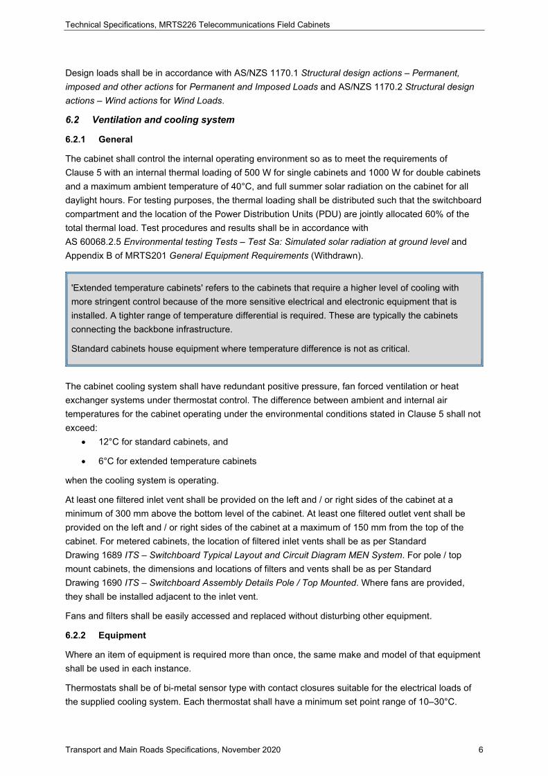
'Extended temperature cabinets' refers to the cabinets that require a higher level of cooling with more stringent control because of the more sensitive electrical and electronic equipment that is installed. A tighter range of temperature differential is required. These are typically the cabinets connecting the backbone infrastructure.
Standard cabinets house equipment where temperature difference is not as critical.
The cabinet cooling system shall have redundant positive pressure, fan forced ventilation or heat exchanger systems under thermostat control. The difference between ambient and internal air temperatures for the cabinet operating under the environmental conditions stated in Clause 5 shall not exceed:
• 12°C for standard cabinets, and
• 6°C for extended temperature cabinets
when the cooling system is operating.
At least one filtered inlet vent shall be provided on the left and / or right sides of the cabinet at a minimum of 300 mm above the bottom level of the cabinet. At least one filtered outlet vent shall be provided on the left and / or right sides of the cabinet at a maximum of 150 mm from the top of the cabinet. For metered cabinets, the location of filtered inlet vents shall be as per Standard Drawing 1689 ITS – Switchboard Typical Layout and Circuit Diagram MEN System. For pole / top mount cabinets, the dimensions and locations of filters and vents shall be as per Standard Drawing 1690 ITS – Switchboard Assembly Details Pole / Top Mounted. Where fans are provided, they shall be installed adjacent to the inlet vent.
Fans and filters shall be easily accessed and replaced without disturbing other equipment.
6.2.2 Equipment
Where an item of equipment is required more than once, the same make and model of that equipment shall be used in each instance.
Thermostats shall be of bi-metal sensor type with contact closures suitable for the electrical loads of the supplied cooling system. Each thermostat shall have a minimum set point range of 10–30°C.
Technical Specifications, MRTS226 Telecommunications Field Cabinets
Transport and Main Roads Specifications, November 2020 7
Filter performance rating shall be classified G4 in accordance with Table 2.1 of AS 1324.1 Air filters for use in general ventilation and air-conditioning – Application, performance and construction, and meet the following requirements:
• filter material density no less than 350 g/m², and
• filtration average arrestance no less than 90%.
Filters shall be installed such that their replacement is done without opening the cabinet.
Fan motors shall be of a construction that exhibits minimal amount of electrical noise output and shall be EMC-shielded to prevent interference with electronic component within the cabinet. Fans shall be of ball-bearing type. The fan motor and bearings shall be suitable for 100% operating duty in the intended operating environment. The fan motor and bearings shall have a MTBF of 40,000 hours based on intended use, at a 90% running duty cycle. The performance of the fans shall be such that the rated airflow of the filters is maintained at all conditions.
6.2.3 Operation and performance
Each thermostat shall operate the connected cooling device(s) once the internal ambient temperature (measured at the top of the cabinet) reaches the set point.
Prior to approval of the cabinet and cooling system design, a prototype of the cabinet and cooling system to be provided under this Contract shall be subject to Factory Acceptance Testing (FAT) to the satisfaction of the Administrator. Hold Point 1
6.3 Dimensions
The cabinet shall house an adjustable full height internal racking system described in Clause 6.8. In addition, 50 mm clear space free of all cables and equipment shall be provided at the front and rear of the cabinet when the cabinet doors are closed. A minimum of 100 mm clear space shall be provided on both sides of the rack framework.
Internal frame heights may be expressed in terms of Rack Units (RU) based on one RU ≅ 44.45 mm.
The dimensions of an unmetered cabinet shall be as defined in Table 6.4.1. For dimensions of metered cabinets, refer to Standard Drawing 1689. The functional internal height shall be taken as the rackable space between the top and bottom bracing of the rack.
The cabinet footprint shall fit onto the layout of the concrete plinth in Standard Drawing 1679 ITS – Telecommunications Field Cabinet Base Installation Details.
6.4 Access doors, gland plates and drain holes
6.4.1 General
Access doors shall be incorporated at the front and rear of the cabinet to provide access to all internal equipment and cables. Each door, when fully open, shall be held at a minimum of 110 degrees from the closed position by a mechanism that operates in a constrained manner (for example, sliding metal door stay or gas struts).
For access door requirements for metered cabinets, refer to Standard Drawing 1689 ITS – Switchboard Typical Layout and Circuit Diagram MEN System.
Technical Specifications, MRTS226 Telecommunications Field Cabinets
Transport and Main Roads Specifications, November 2020 8
The size of the door openings shall be as close as practicable to the external dimensions of the cabinet to maintain ease of access to equipment and the racking system. Doors and fixings shall be consistent with the material and construction requirements of the cabinet.
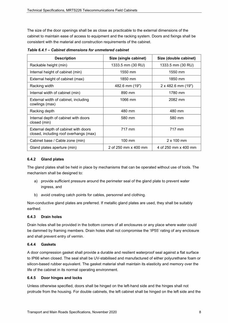
Table 6.4.1 – Cabinet dimensions for unmetered cabinet
Description Size (single cabinet) Size (double cabinet)
Rackable height (min) 1333.5 mm (30 RU) 1333.5 mm (30 RU)
Internal height of cabinet (min) 1550 mm 1550 mm
External height of cabinet (max) 1850 mm 1850 mm
Racking width 482.6 mm (19") 2 x 482.6 mm (19")
Internal width of cabinet (min) 890 mm 1780 mm
External width of cabinet, including cowlings (max)
1066 mm 2082 mm
Racking depth 480 mm 480 mm
Internal depth of cabinet with doors closed (min)
580 mm 580 mm
External depth of cabinet with doors closed, including roof overhangs (max)
717 mm 717 mm
Cabinet base / Cable zone (min) 100 mm 2 x 100 mm
Gland plates aperture (min) 2 of 250 mm x 400 mm 4 of 250 mm x 400 mm
6.4.2 Gland plates
The gland plates shall be held in place by mechanisms that can be operated without use of tools. The mechanism shall be designed to:
a) provide sufficient pressure around the perimeter seal of the gland plate to prevent water ingress, and
b) avoid creating catch points for cables, personnel and clothing.
Non-conductive gland plates are preferred. If metallic gland plates are used, they shall be suitably earthed.
6.4.3 Drain holes
Drain holes shall be provided in the bottom corners of all enclosures or any place where water could be dammed by framing members. Drain holes shall not compromise the ‘IP55’ rating of any enclosure and shall prevent entry of vermin.
6.4.4 Gaskets
A door compression gasket shall provide a durable and resilient waterproof seal against a flat surface to IP66 when closed. The seal shall be UV-stabilised and manufactured of either polyurethane foam or silicon-based rubber equivalent. The gasket material shall maintain its elasticity and memory over the life of the cabinet in its normal operating environment.
6.4.5 Door hinges and locks
Unless otherwise specified, doors shall be hinged on the left-hand side and the hinges shall not protrude from the housing. For double cabinets, the left cabinet shall be hinged on the left side and the
Technical Specifications, MRTS226 Telecommunications Field Cabinets
Transport and Main Roads Specifications, November 2020 9
right cabinet on the right side. Hinges shall be of a design such that the hinge pins cannot be removed when the door is in the closed position. Preference shall be given to concealed hinges.
Locking / unlocking of each door shall be effected by single key operation. The lock shall operate a three-point latching mechanism with pins extending from the top, centre and bottom of the non-hinged side of the door. The door shall house a flush mounting handle incorporating a dust cover and capable of accepting a Half Euro Profile locking cylinder (DIN 18252 Profile cylinder for door locks – Terminology, dimensions, requirements, test methods and marking / EN1303 Building hardware – cylinders for locks) with restricted keying. The three-point latching mechanism and handle shall be 316 Stainless steel.
Two keys shall be supplied with each cabinet, keyed to the department's requirements (only if using standard mechanical keys).
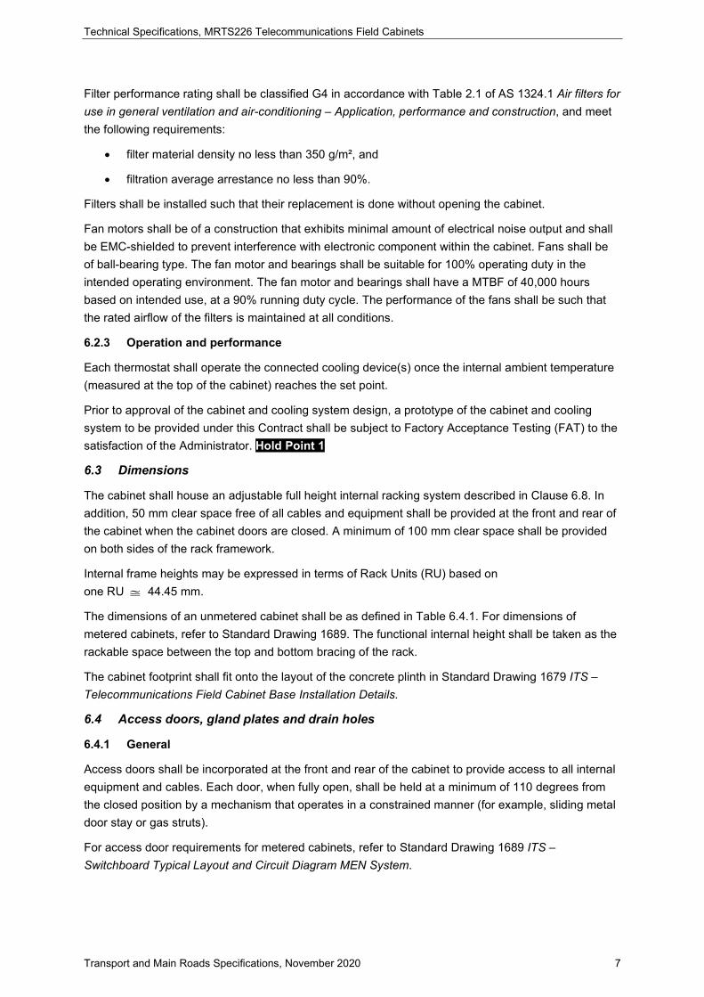
Stainless steel swing handles have been incorporated to enhance the longevity and robustness of the locking system.
6.5 Installation of CyberLocks
Electronic Half Euro Profile CyberLocks are to be installed on cabinet doors where required by the department. Once installed, each CyberLock is required to be labelled with the manufacturer's designated barcode / serial numbers supplied. These labels are to be located inside the cabinet door adjacent to the CyberLock with easy accessibility for barcode scanners. Serial identification numbers for both CyberLocks and cabinets shall to be documented and supplied to the Principal upon delivery.
CyberLocks must be configured to be opened anticlockwise.
Cyberkeys are not to be supplied with the cabinet.
6.6 Programing CyberLocks
CyberLocks are to be programmed by Transport and Main Roads Districts. If another entity separate to the department has possession of site during construction, the department has the option to enable third-party access to the site for the duration of the project. Upon project completion / handover, the locks will then be reprogrammed to remove third-party access to the cabinets.
6.7 Cyberkeys
Cyberkey can only be programmed by Transport and Main Roads. All keys will be assigned to individuals, not corporations or organisations.
All keys used / acquired by any third parties need to be registered / configured by the department before use.
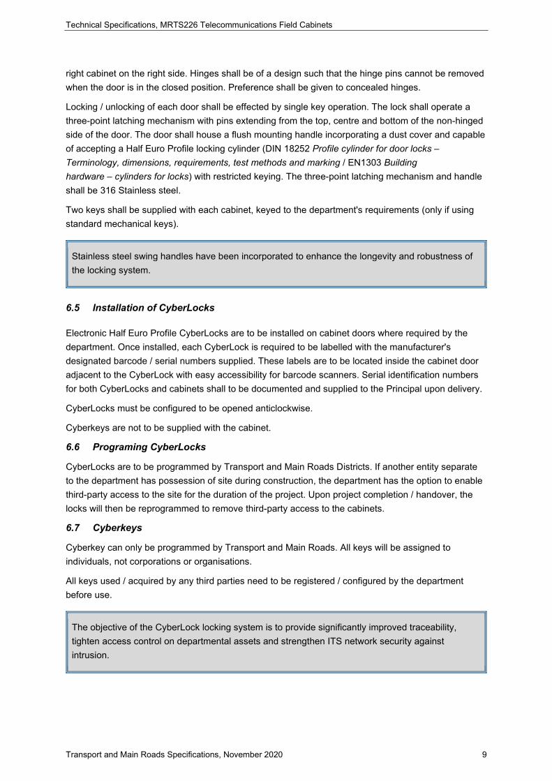
The objective of the CyberLock locking system is to provide significantly improved traceability, tighten access control on departmental assets and strengthen ITS network security against intrusion.
Technical Specifications, MRTS226 Telecommunications Field Cabinets
Transport and Main Roads Specifications, November 2020 10
6.7.1 Document storage pocket
A pocket shall be provided on the inside lower half of each access door to provide space for the storage of site documentation. The pocket shall be sized to completely shroud unfolded, laminated A3-sized Standard Drawings with long edge in the horizontal plane. The pocket shall be minimum 20 mm in depth, 430 mm in width and 220 mm in height. The pocket shall include at least two equi-spaced finger slots extending at least 100 mm from the base of the pocket to assist in the removal of plans.
6.8 Equipment racks
The cabinet shall be supplied with an adjustable internal racking system of punched rails in each corner to the full height of the cabinet. The vertical frame of the racking system shall be segmented to allow mounting of 19 inch (482.6 mm) and Euro metric 21 inch (533.4 mm) equipment at alternating segments. Each segment shall be 10 standard Rack Units (10RU). All segments of the racking system shall initially be set to 19 inch sizing. Double cabinets shall have the racking system duplicated for both left and right cabinets. A minimum equipment mounting depth of 480 mm shall be provided between the front and back of the rack.
All fixings (nuts, bolts and screws and the like) shall be metric threads.
The racking system shall be supplied with a proprietary relocatable fixed shelf and a relocatable sliding shelf. The fixed shelf shall be positioned to provide 5RU spare space above the shelf. The shelves shall be manufactured from perforated 1.5 mm steel sheet with a corrosion-proof coating (or annealed zinc). The shelves shall be capable of supporting a 50 kg static surface load without deformation.
6.9 Cable management
Cable management shall be in the form of slotted duct with covers, cable shunting rings or similar rigid formed systems. These products shall be manufactured from a non-conductive material and be of a design that shall not damage the cables being secured.
The field cabinets shall have a cable trunking / management system down the full height of both sides of the cabinet. The cable trunking / management system shall be capable of holding a 50 mm diameter cable loom. It shall be installed such that it does not interfere with the internal racking system, while allowing easy maintenance access to cables within the trunking system. Horizontal cable management shall be provided where appropriate. At least 50% spare capacity shall be provided in each cable management systems.
Labels shall not be affixed to duct covers.
6.10 Danger sign
A suitably sized danger sign, with relative dimensions as shown in Clause 2.3.4 of AS 1319 Safety signs for the occupational environment and Appendix C thereof, shall be fixed to the inside of the access door. The warning message on the legend within the white rectangle shall be 240 VOLTS AC.
6.11 Surface finish
All cabinet surfaces shall have a durable gloss finish that may be either integral with the cabinet material or applied to its surfaces. The finish chosen shall comply with AS/NZS 1580.457.1 Paints and related materials – Methods of test – Resistance to natural weathering for resistance to natural weathering. Resistance to corrosion shall be tested to AS 2331.3.1 Methods of test for metallic and
Technical Specifications, MRTS226 Telecommunications Field Cabinets
Transport and Main Roads Specifications, November 2020 11
related coatings, Method 3.1: Corrosion and related property tests – Neutral salt spray test (NSS test) and for test duration of 1500 hours. The finish chosen shall have excellent abrasion resistance (AS 1580.403.2 Paints and related materials – Methods of test, Method 403.2: Abrasion resistance) and cross-cut adhesion rating better than one as per AS 1580.408.4 Paints and related materials – Methods of test Method 408.4: Adhesion (crosscut). Where an integral finish is used, the material shall be such as to allow an alternative finish to be applied to the surface in the field without special preparation.
A suitable finish shall be applied to the cabinet, depending on the material of manufacture, for an expected life span of 20 years when installed in a roadside environment in Queensland as specified in Clause 5 Environmental conditions of this Technical Specification. This finish shall be applied irrespective of the cabinet's intended location.
The cabinet shall be treated with the required surface or primer preparation for the material of construction. The primer / undercoat shall be of powder-coat type and applied to the surface in accordance with the manufacturer's specifications. Provide at least one full coat of primer for stainless steel (Grade 316) and marine grade aluminium.
Paintwork shall be a ripple-free finish of a thickness range between 40–70 microns (not including surface preparations or primers) of either a powder coat or wet paint type.
The surface colour shall be Smoke Blue (AS 2700: Colour No. T33).
The quality and FAT procedures on surface preparation, primer / undercoat application and final finish application shall be submitted for approval prior to fabrication. Hold Point 2
6.12 Mounting surface, facilities and structural integrity
Unless otherwise specified, the single and double cabinet shall be mounted onto a concrete plinth having the fixing holes as shown in Standard Drawing 1679 ITS – Telecommunications Field Cabinet Base Installation Details. The concrete plinth design shall be flat such that the cabinet does not move due to any unevenness of the plinth. The gap between the plinth and enclosure shall be vermin proof and prevent corrosion of the enclosure or its fixings. The suitability of the concrete plinth for mounting the intended field cabinet in accordance with Standard Drawing 1679 ITS – Telecommunications Field Cabinet Base Installation Details shall be approved by an engineer with the appropriate RPEQ. Electrical and telecommunication conduits shall be installed between the cabinet and pits as shown on Standard Drawing 1679 ITS – Telecommunications Field Cabinet Base Installation Details and in accordance with MRTS91 Conduits and Pits.
Cabinets mounted on poles or mast arms, such as CCTV cabinets, shall be in accordance with MRTS97 Mounting Structures for Roadside Equipment or as per Standard Drawing 1627 Road lighting – Switchboard – Top Mounted and Standard Drawing 1628 Road lighting – Post – Top Mounted Switchboard for pedestal mount or top mounting.
6.12.1 Lifting and transportation points
Where the fitted-out enclosure (including all operational equipment other than batteries) cannot be manually lifted and held by a single person (within workplace health and safety limits) during installation, lifting anchors shall be provided. The lifting anchor(s) shall be integral with the enclosure and prevent moisture ingress to the enclosure. Seals around the lifting anchor(s) are not permitted.
Anchors shall be capable of supporting the fitted-out enclosure complete with all operational equipment such as racks, fans, filters and switchboards. The integrity of the enclosure when being

Technical Specifications, MRTS226 Telecommunications Field Cabinets
Transport and Main Roads Specifications, November 2020 12
lifted shall be in accordance with Clause 9.4 of IEC 62208 Empty enclosures for low-voltage switchgear and control-gear assemblies – General requirements, with a test load of at least 250 kg for single cabinets, and 500 kg for double cabinets, in addition to the fully-fitted enclosure weight (excluding batteries).
If eyebolts are used as lifting anchors, the axial strength of the eyebolts shall be in accordance with Table 2 in Clause 6.1 of AS 2317.1 Lifting points, Part 1: Collared eyebolts and collared eyenuts – Grade 4.
7 Installation
The cabinet shall be installed on a mounting surface in accordance with Clause 6.12. The Contractor shall allow access for inspection of all mounting surfaces by the Administrator prior to installation of cabinets. Hold Point 3
After installation of the cables, the conduits shall be sealed to prevent vermin entry. Witness Point 1
8 Storage
The Contractor shall take all reasonable care when storing field cabinets prior to installation. They shall be stored upright in a safe, dry and secure location until required. They shall not be stored directly on the ground.
9 Electrical requirements
9.1 Electrical safety
The electrical equipment and associated wiring within the cabinet shall comply with the relevant requirements of AS/NZS 3100 Approval and test specification – General requirements for electrical equipment.
The switchboard and all electrical cabling within the cabinet shall comply with the relevant requirements of AS/NZS 3000.
The cabinet site works incorporating conduits for power and telecommunications cables shall comply with the requirements of the Queensland Electricity Act 1994, AS/NZS 3000, AS/CA S009 Installation requirements for customer cabling (Wiring rules) and MRTS91 Conduits and Pits.
The switchboard shall provide a degree of protection from live parts to meet the classification of IP44 in accordance with AS 60529.
9.2 Power supply
The Contractor shall arrange for mains power to be connected to the switchboard in accordance with the requirements of MRTS210 Provisions of Mains Power.
9.2.1 Metering
In a metered cabinet, the metering equipment shall occupy the space behind the switchboard and its depth shall not exceed the midpoint of the cabinet depth. The metering enclosure shall not exceed 12 RU. All dimensions and electrical wiring shall be in accordance with the requirements of the Queensland Electricity Connection and Metering Manual – Service and Installation Rules (QECMM).
Technical Specifications, MRTS226 Telecommunications Field Cabinets
Transport and Main Roads Specifications, November 2020 13
9.2.2 Standby generator connection
Where required by the Contract, the field cabinet shall have provision for fitting all of the facilities required for connection of an external generator as specified within this clause, in order to energize the installation in the event of unavailability of mains power. The connector shall be a three-pin input connector complying with AS/NZS 3112 Approval and test specification – Plugs and socket outlets and rated at 15A.
AS 2578-2009 Traffic Signal Controllers which previously provided guidance on this topic has been withdrawn. In this absence of national advice on this topic, the following information, extracted from that withdrawn Standard, has been reproduced for the reference of readers.
The generator connection facility shall include:
a) Inlet for generator cable
The inlet for the cable from the generator shall be large enough to permit a cable socket of diameter 60 mm to pass through. It shall not be possible to open the inlet cover from outside the cabinet.
When the facilities are installed, and the cable is connected, it shall not be possible to subject the plug connection to any forces if the cable is pulled from outside the cabinet housing.
b) Anchoring of generator to the controller housing
Facilities shall be included to add an eye-bolt to the cabinet housing to allow the generator to be secured to the housing. When fitted, the eye-bolt shall be able to withstand a static pulling force of 2000 N from any direction. The eye-bolt shall have an eye opening of nominally 25 mm diameter.
c) Connection for external generator
Facilities shall be provided to add a male 3-pin mains voltage connector inside the cabinet housing to accept the 3-pin female connector on the cable from the external generator. The connector shall be rated at either 10 A or 15 A, as specified by the purchaser, and shall provide connections for active, neutral and earth.
d) Switch to change power source
Facilities shall be provided to add a change-over switch to manually select either the mains supply or the generator supply. The switch shall be labelled to clearly indicate the switch positions. The switch shall be rated at 32 A, and shall be wired to switch both the active and neutral lines.
The operation of the switching contacts shall provide adequate break-before-make operation to prevent a short-circuit between the two supply sources.
e) Indication of presence of power
Two labelled indicator lights shall be provided to indicate the presence of voltage on the mains supply and the generator supply.

Technical Specifications, MRTS226 Telecommunications Field Cabinets
Transport and Main Roads Specifications, November 2020 14
9.3 Switchboard
The switchboard component list has been deleted as this is included in Standard Drawing 1689 ITS – Switchboard Typical Layout and Circuit Diagram MEN System along with the switchboard layout and single line drawing.
The switchboard and associated components shall be in accordance with Standard Drawing 1689 ITS – Switchboard Typical Layout and Circuit Diagram MEN System.
Each cabinet shall be supplied with a 19-inch rack mountable modular switchboard. The switchboard shall be mounted in the upper quarter of the rack and shall have a depth not exceeding the midpoint of the cabinet depth. The switchboard shall have a height of no greater than 8RU (356 mm approx). The top of the switchboard shall be at least 120 mm below the level of the door opening. All electrical components shall be suitable for operation on a supply complying with the Queensland Electricity Regulation 2006.
All power supply wiring within the switchboard shall be a minimum of 2.5 mm² (7/0.67) PVC, except for lighting and fan circuits where a minimum of 1.5 mm² (7/0.50) PVC is acceptable. All cabinets and switchboards shall be bonded to the MEN system by a suitable cabling and earth stake as per AS/NZS 3000. Only one wire shall be connected to each terminal. Bridging terminals shall be used for parallel connections.
All electrical design, wiring and associated equipment shall comply with the requirements of AS/NZS 3000.
Standard Drawing 1689 ITS – Switchboard Typical Layout and Circuit Diagram MEN System provides a typical circuit diagram and switchboard layout. For different load requirements or different surge ratings, different components may be used; however, the layout and general arrangement should remain fairly standard.
9.4 Arrangement of terminals
Each terminal shall be clearly and indelibly identified. The terminal assembly shall be arranged so that:
a) the connecting cables can be formed in a neat manner, and
b) the individual conductors can be connected or disconnected without disturbing other connections.
9.5 Connection of equipment
Equipment shall be energised from the cabinet either:
• via power socket outlets (SOs) as described in Clause 9.5.1, or
• be hardwired as described in Clause 9.5.2.
The preference is to have SO connection whenever possible as is the case for metered cabinets. For unmetered cabinets, connection of equipment shall be as determined by the requirements of the local electricity entity.
Technical Specifications, MRTS226 Telecommunications Field Cabinets
Transport and Main Roads Specifications, November 2020 15
Whether equipment is to be hardwired or connected to SOs, in part depends on whether the cabinet is metered or unmetered.
The decision to use metered or unmetered cabinets is subject to project requirements and agreement between the Principal and the electricity entity. For unmetered supplies, the electricity entity will require load details of the connected equipment as well as details of the number of, and the consumption requirements for, the SOs planned for each installation. Connection of equipment to SOs may not be acceptable to power supply authorities in some districts.
For metered supplies, the Principal shall record load details of the connected equipment as well as details of the number of, and the consumption requirements for, the SOs planned for each installation as part of the project documentation, but may not be required to provide these records to the electricity entity.
9.5.1 Power socket outlets
Where socket outlets are used as part of the initial design, only Residual current device (RCD)-protected double SOs compliant with AS/NZS 3112 shall be installed in the cabinet. Additional SOs for energizing equipment mounted in the cabinet shall be installed as per the requirements of the Contract. The number of the additional outlets shall match the desired number of equipment.
All SOs shall:
• be wired to an individual sub-circuit
• be arranged such that the orientation of each earth pin is vertical
• be mounted vertically on the rear side of the rack frame so as not interfere with equipment racking and cabling
• be easily accessible from both the front and rear of the cabinet
• have plug / power supply retention capability for each product supplied as part of the Contract
• have the necessary earth leakage protection where required
• in the absence of RCD protection, be affixed with labels as per MRTS201 General Equipment Requirements worded ‘No RCD’, and
• if mounted on the same plate, be adequately spaced to enable mounting of adaptors of various designs and sizes.
9.5.2 Hardwired equipment
Where equipment is hardwired, it shall be connected using industry standard connectors and terminal panels to enable connection of equipment requiring AC or DC input.
DC supplies rated 12V and 24V with the appropriate terminal panels, enclosed in IP44-rated enclosure, shall be provided for equipment requiring DC power. The connection of the DC supplies to mains power shall be stable, secure and shielded from exposure to inadvertent access.
All terminal panels shall be arranged as per Clause 9.4 and enclosed in IP44-rated enclosure.
Technical Specifications, MRTS226 Telecommunications Field Cabinets
Transport and Main Roads Specifications, November 2020 16
9.6 Cabinet lighting
Each cabinet shall have two LED luminaires that are:
• rated no more than 7 watts
• mounted within 150 mm of the top of the cabinet (one each at front and rear)
• rack mounted or directly mounted inside the cabinet above each door
• switched by a door switch, and
• hard wired to the lighting subcircuit.
The LED luminaires shall be mounted in a manner such that they do not interfere with equipment racking and cabling and do not shine directly into eyes of maintenance personnel.
The micro-switches shall be of a weatherproof construction with a minimum rating of IP56 and wired such that the relevant luminaire is switched on upon opening an access door. Each micro-switch shall have two sets of contacts and a minimum MTBF of 10,000 switching operations.
9.7 Radio frequency interference
The electromagnetic interference produced by the equipment supplied and installed in the field cabinet by the Contractor shall not exceed the limits prescribed in AS/NZS 1044 Limits and methods of measurement of radio interference characteristics of household electrical appliances, portable tools and similar electrical apparatus (Superseded).
All equipment supplied by the Contractor shall include documentation detailing the equipment conformance to radio frequency interference, electromagnetic compatibility and other relevant Authority compliance. This documentation shall be submitted to the Administrator on delivery of the cabinet.
9.8 Protection against electrical transients and over-voltage
The section on surge diverters has been deleted as the surge filter provides suitable protection, making the diverter unnecessary. The requirement for surge protection of copper cables exiting the cabinet to field equipment has been added.
9.8.1 General
The cabinet shall incorporate protection against electrical transients and over-voltage. The installation shall follow the recommended practices for MEN systems, specified in AS 4070 Recommended practices for protection of low-voltage electrical installations and equipment in MEN systems from transient overvoltages for protection of low-voltage electrical installations and equipment from transient over-voltages.
The cabinet installation shall follow the general guidelines for the protection of persons and property from hazards arising from exposure to lightning in accordance with AS / NZS 1768 Lightning protection.
The switchboard shall also include the necessary devices to protect all equipment being housed in the cabinet from electrical transients and over-voltage.
Technical Specifications, MRTS226 Telecommunications Field Cabinets
Transport and Main Roads Specifications, November 2020 17
A surge filter shall be provided to protect the cabinet from surges entering via the mains. Additional surge protection must be provided for any copper cables exiting the cabinet and connecting to field equipment.
9.8.2 Surge filters
A surge filter shall be provided immediately after the incoming supply fuse switch and on the line side of the earth leakage protective devices. The surge filter shall provide protection against multiple impulses caused by lightning or other transient disturbances. The surge filter shall be connected between phase and neutral, phase and earth, and neutral and earth.
The surge filter shall have a minimum load current rating of 20 A per phase.
The surge filter shall have a single shot 8/20 µs rating of 20 kA per mode and shall be suitably rated to withstand multiple impulses as defined by location category B in AS / NZS 1768.
The surge filter shall be based upon metal oxide varistor (MOV) technology. The line side MOVs shall be internally fused such that they are disconnected if the unit experiences a surge that exceeds its rating.
The surge filter shall have visual tags and LED indicating ‘status’. The status visual tag and LED shall extinguish when the MOV fuse operates, when power to the unit is lost, or when the unit experiences a thermal overload. In the event of a thermal overload, the protection shall remain in circuit.
A voltage free changeover contact (alarm output) shall be incorporated in the surge filter. This shall activate upon any MOV failure, power failure or temperature overload condition. The contact shall be isolated to 4kV to all active circuitry.
The surge filter shall be rated for a nominal operating voltage of 240 V and a maximum operating voltage of 275V rms. Let through voltage for a 6 kV 1.2/50 µs, 3 kA 8/20 µs impulse shall be less than 600 V when measured at the surge filter terminals.
10 Telecommunication requirements
10.1 Provision for connection to telecommunication lines
Provision for telecommunications lines shall be provided in accordance with the requirements of AS/CA S008 Requirements for customer cabling products, AS/CA S009 and AS/NZS 3085.1 Telecommunications installations – Administration of communications cabling systems – Basic requirements.
The cabinet works incorporating conduits for communication cables shall comply with the requirements of AS/CA S009.
10.2 Telecommunications service
Where specified, the Contractor shall act as the Principal's agent in arranging for connection of a telecommunications service to the site in the name of the Principal.
Within 14 days of written request, the Principal shall provide relevant details to enable the Contractor to complete the forms required by the telecommunications entity.

Technical Specifications, MRTS226 Telecommunications Field Cabinets
Transport and Main Roads Specifications, November 2020 18
11 Documentation
The documentation requirements defined in MRTS201 General Equipment Requirements apply to this Technical Specification. Additional documentation requirements relevant to this Technical Specification are defined below.
Prior to the commencement of manufacturing works, the Contractor shall prepare and request approval of the Principal / Administrator of three copies of the following documents:
a) fabrication and assembly Standard Drawings, detailing all of the components to be installed
b) manufacturer's specifications of cabinet and of all major components detailing ratings and performance characteristics
c) a schematic layout of components, building details and interconnection diagrams
d) recommendations for routine maintenance tasks, and
e) recommendations on spare parts.
Hold Point 4
The Contractor shall provide to the satisfaction of the Principal / Administrator, the following documents prior to the delivery of the cabinets to site:
a) a statement confirming the warranty provisions associated with the field cabinet and associated equipment
b) compliance details of all components as required or implied under this document, and
c) records of tests conducted by the Contractor to demonstrate compliance to this Technical Specification.
Hold Point 5
Prior to issue of Practical Completion, the Contractor shall provide a laminated A3-sized copy of the ‘As Constructed’ switchboard schematic and wiring diagrams, together with all FATs, commissioning and operating / maintenance documentation to the satisfaction of the Administrator.
12 Guarantee / Warranty
The Contractor shall guarantee the equipment supplied for a period of 12 months after the date of practical completion.
13 Spare components
The Contractor shall provide a schedule of spare components, and prices, recommended for retention for service and / or fault maintenance purposes and shall maintain a stock of such items. The Contractor shall guarantee that such spare components will be available for a minimum of seven years after the date of practical completion.
The Principal may elect to purchase all or some of the recommended maintenance stocks upon completion of the warranty period.
14 Packaging and shipping
The equipment shall be securely packed and sealed to prevent damage prior to shipping. The Contractor shall repair or replace to the satisfaction of the Principal / Administrator, any damage that
Technical Specifications, MRTS226 Telecommunications Field Cabinets
Transport and Main Roads Specifications, November 2020 19
occurs prior to issue of Practical Completion. Costs associated with the repair or replacement shall be at the Contractor's expense.
15 Non-conforming product
Equipment that does not meet the specified design quality and weather resistance tests to the satisfaction of the Administrator shall be rejected.
The Contractor shall rectify any consequential damage to the satisfaction of the Administrator. The Contractor shall bear all costs associated with the replacement of the non-conforming product and / or consequential damage.
16 Sample for evaluation
The Contractor shall provide a sample of a complete cabinet for evaluation in accordance with Clause 4.2 of MRTS201 General Equipment Requirements at least 14 days prior to the planned commencement of fabrication.
17 Acceptance testing and certification
The testing, commissioning and certifications requirements defined in MRTS201 General Equipment Requirements apply to this Technical Specification. In addition, test sheets shall demonstrate compliance with the technical requirements of this Technical Specification prior to the delivery of the equipment to site. Hold Point 6
18 Program schedule
Within 14 days of the Letter of Acceptance, the Contractor shall submit and maintain, a program schedule that includes: Milestone
• detailed Standard Drawings, manufacturers' specifications and schematic layout of components for approval by the Principal
• submit quality plans for fabrication approval
• submit FAT Plan
• where applicable, witness of factory tests by the Principal, and submission of test certificates, and
• delivery.
The Contractor shall update the program of works and provide to the Administrator on a fortnightly basis.
19 Training
The training requirements defined in MRTS201 General Equipment Requirements apply to this Technical Specification.