transport and main roads specifications mrts66 driven .../media/busind/techstdpubs/specifications...
TRANSCRIPT
Technical Specification Transport and Main Roads Specifications MRTS66 Driven Steel Piles July 2017

Transport and Main Roads Specifications, July 2017
Copyright
http://creativecommons.org/licenses/by/3.0/au/
© State of Queensland (Department of Transport and Main Roads) 2017
Feedback: Please send your feedback regarding this document to: [email protected]

Transport and Main Roads Specifications, July 2017 i
Contents
1 Introduction ....................................................................................................................................1
2 Definition of terms .........................................................................................................................1
2.1 General ........................................................................................................................................... 1
2.2 Notation ........................................................................................................................................... 3
3 Referenced documents .................................................................................................................4
4 Quality system requirements .......................................................................................................4
4.1 Hold Points, Witness Points and Milestones .................................................................................. 4
4.2 Construction procedures ................................................................................................................. 5
4.3 Conformance requirements ............................................................................................................ 6
5 Steel piles .......................................................................................................................................7
5.1 Requirements for steel piles ........................................................................................................... 7 5.1.1 General ...........................................................................................................................7 5.1.2 Dimensional tolerances ..................................................................................................7 5.1.3 Supplied lengths .............................................................................................................7 5.1.4 Hot-dipped galvanising ...................................................................................................7
5.2 Transport, handling and storage ..................................................................................................... 7 5.2.1 General ...........................................................................................................................7 5.2.2 Certification of equipment ...............................................................................................8 5.2.3 Mass of loads .................................................................................................................8 5.2.4 Escorts and pilots ...........................................................................................................8 5.2.5 Support of units during transport ....................................................................................8 5.2.6 Lifting ..............................................................................................................................8 5.2.7 Support of piles during storage ......................................................................................8
6 Pre-boring .......................................................................................................................................8
7 Pile driving ......................................................................................................................................9
7.1 General ........................................................................................................................................... 9
7.2 Test pile ........................................................................................................................................ 10
7.3 Changes in founding level ............................................................................................................ 10
7.4 Location and tolerances ................................................................................................................ 11
7.5 Pile hammer .................................................................................................................................. 11 7.5.1 General ........................................................................................................................ 11 7.5.2 Conforming and Design hammer ................................................................................ 11 7.5.3 Alternative hammer ..................................................................................................... 12
7.6 Pile helmet .................................................................................................................................... 14
7.7 Driving procedure ......................................................................................................................... 14
7.8 Pile driving log............................................................................................................................... 15
7.9 Monitoring of pile driving (PM) ...................................................................................................... 15
7.10 High Strain dynamic testing (HSDT) ............................................................................................. 16
7.11 Pile capacity and pile set .............................................................................................................. 16
7.12 Pile penetration ............................................................................................................................. 17 7.12.1 Piles refuse above minimum penetration level ............................................................ 18 7.12.2 Piles do not achieve capacity below founding level .................................................... 18 7.12.3 Restrike ....................................................................................................................... 18

Transport and Main Roads Specifications, July 2017 ii
7.13 Follower ........................................................................................................................................ 18
8 Trimming of pile head ................................................................................................................ 19
9 Extension to piles ....................................................................................................................... 19
10 Bond bars .................................................................................................................................... 20
11 Approvals of changes ................................................................................................................ 20
12 As constructed records ............................................................................................................. 20
13 Supplementary requirements .................................................................................................... 21

Technical Specification, MRTS66 Driven Steel Piles
Transport and Main Roads Specifications, July 2017 1
1 Introduction
This Technical Specification applies to the supply and installation of driven steel piles for structures but not generally including marine structures. The pile types included in this Technical Specification, include, but are not limited to, UBP, UC and I sections, as well as various hollow steel sections including pipe sections, spirally wound and other welded tube sections.
Generally for marine works the pile driving component is incorporated into the relevant MRTS300 series of Technical Specifications.
This Technical Specification is not applicable to temporary works or to sheet piling activities, unless explicitly included by the contract documents.
This Technical Specification is based on MRTS65 Precast Prestressed Concrete Piles and where ever possible uses the same words as that Technical Specification.
This Technical Specification shall be read in conjunction with MRTS01 Introduction to Technical Specifications, MRTS50 Specific Quality System Requirements, MRTS66 Driven Steel Piles, and other Technical Specifications as appropriate.
This Technical Specification forms part of the Transport and Main Roads Specifications Manual.
The following items require the use of products or processes which have been registered by the department.
Table 1 – Registered Suppliers
Clause Registered Suppliers
5 Fabrication of piles
9 Cold Galvanising Paint Details of all approved products and suppliers can be found in the departmental website at www.tmr.qld.gov.au/business-industry/Business-with-us/Approved-products-and-suppliers.aspx
2 Definition of terms
2.1 General
The terms used in this Technical Specification are defined in Clause 2 of MRTS01 Introduction to Technical Specifications.
In addition, terms listed in Table 2.1 are also applicable to the Technical Specification.
Term Definition
Alternative hammer A pile driving hammer, which is lighter than the Conforming hammer which must meet or exceed the requirements of Table 7.5.3. The use of such a hammer must be approved by the Administrator prior to use.
Conforming hammer A pile driving hammer of mass and rated energy, which meets or exceeds that defined in Clause 1 of Annexure MRTS66.1 and complies with the requirements of Table 7.5.2. That is it conforms to (or exceeds) the capability of the Design hammer(s).

Technical Specification, MRTS66 Driven Steel Piles
Transport and Main Roads Specifications, July 2017 2
Term Definition
CAS Construction Administration System
Design hammer The pile driving hammer (or hammers) as detailed by the designer in Clause 1 of Annexure MRTS66.1 and which conforms to the requirements of Table 7.5.2.
Design founding level The pile tip level shown on the plans (or elsewhere) which represent the designers assumed level to which the piles are to be driven. Since founding level is only an estimate the accuracy of this level may be assumed to be ±1 m. That is, a pile founding within 1.0 m of the design founding level may be assumed to be at the founding level for all purposes except payment in which case the actual level is used.
Free length During driving, the unsupported section of a pile above ground level.
Flying leaders A support structure or frame for the pile hammer which, rather than being attached to both the ground and a crane or similar piece of equipment (ordinary leader), is supported by the pile and / or a system of guy cables or only by a crane
Follower A rigid section, typically of steel used to temporally extend a pile to facilitate driving to, or below, ground level.
Geotechnical Engineer An RPEQ engineer or an experienced engineer working under the direct control of an RPEQ engineer who is registered as a Geotechnical Engineer by the Board of Professional Engineers Queensland (BOPEQ). An experienced with extensive geotechnical experience and registered as a Civil Engineer by the BOPEQ is deemed to be equivalent.
HSDT High Strain Dynamic Testing, commonly known by the proprietary term PDA™ testing
High Strain Dynamic Testing
A device consisting of sensors attached to the pile, associated electronics and software used to monitor and dynamically analyse the pile during most (if not all) of the driving process. See MRTS68 Dynamic Testing of Piles.
Job hammer The hammer actually used on the job. It may be either a Conforming hammer or an Alternative hammer. Note the job hammer may change during the project but only with the approval of the Administrator.
Minimum penetration The minimum level to which the pile must be driven to meet the design scour and or fixity requirements. Minimum penetration is listed in Clause 4 of Annexure MRTS66.1, and may also be shown on the relevant drawings. The minimum penetration length is determined from the “Minimum penetration level” and the level from which pile driving is undertaken.
Nominal refusal A set of typically 2.5 mm per blow with the hammer working at the energy nominated in Annexure MRTS66.1. This set is so low that the pile is deemed to have refused.
Pad The temporary surface(s) or embankment(s), usually purpose built, constructed to support the pile driving equipment, cranes and ancillary equipment during pile driving. They may be constructed from fill type materials with or without special panels to further distribute the loads imposed by the equipment. The pad must be certified as being adequate and capable of resisting all the applied loads
PM Piling Monitor: A device used to monitor the set, temporary compression, energy input and a range of other parameters during all or part of the driving process.

Technical Specification, MRTS66 Driven Steel Piles
Transport and Main Roads Specifications, July 2017 3
Term Definition
Pile A steel pile or a pile segment (top, middle or bottom) in the case of a spliced pile.
Rake For non-vertical piles, the deviation of the pile from the vertical. Rake may be in the plane of the line of the pier or abutment piles or at some specified orientation from the plane of the pier or abutment line of piles.
RPEQ A Registered Professional Engineer of Queensland, so recognised by the Board of Professional Engineers of Queensland.
Set Permanent displacement of a pile after a full blow of the hammer. Typically measured as the average of 10 consecutive blows.
Test pile Any pile designated as a test pile in the contract documents as a test pile, and the first pile to be driven in any pier or abutment and / or any pile on which a HSDT has been undertaken.
UBP, UC, I Universal Bearing Pile; Universal Column; I beam.
2.2 Notation
The following symbols are used in this Technical Specification.
Table 2.2 – Notation
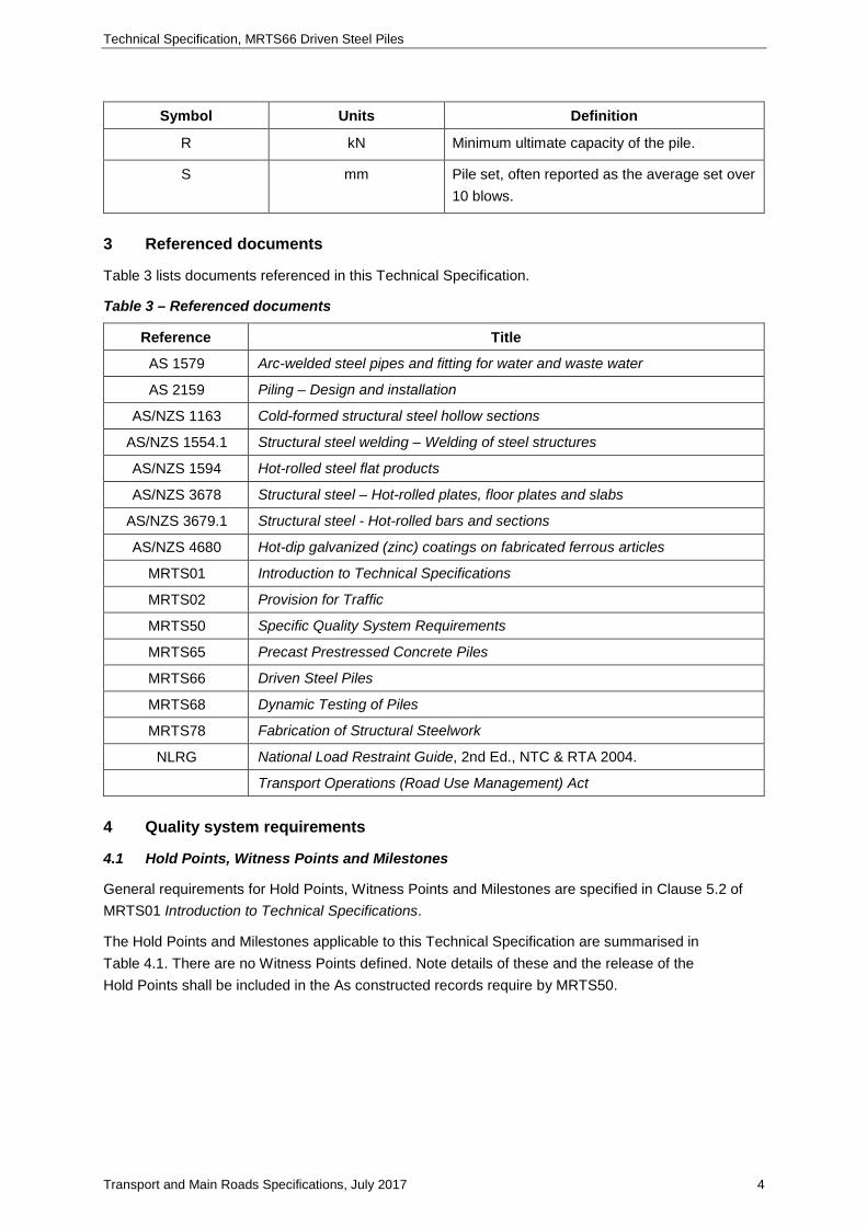
Symbol Units Definition
APSTTA - As Previously Supplied To THE Administrator
C mm Combined temporary compression of the helmet cushion(s), pile and adjacent ground.
e - Coefficient of restitution.
E tonne.m Energy input per hammer blow.
ef - Efficiency of the hammer blow.
Er tonne.m Manufacturers rated energy output of the hammer.
H m Overall height of hammer fall.
L m Overall length of the pile.
Mf tonnes Total mass of the fixed part of the hammer and associated gear attached to the top of the pile which is accelerated by the hammer impact. It excludes the mass of the falling part of the hammer. Typically includes the mass of the hammer frame, anvil, helmet and cushioning, but not the falling part of the hammer.
Mm tonnes Mass of falling part of the hammer.
Mp tonnes Mass of pile.
N/A - Not Applicable.
Technical Specification, MRTS66 Driven Steel Piles
Transport and Main Roads Specifications, July 2017 4
Symbol Units Definition
R kN Minimum ultimate capacity of the pile.
S mm Pile set, often reported as the average set over 10 blows.
3 Referenced documents
Table 3 lists documents referenced in this Technical Specification.
Table 3 – Referenced documents
Reference Title
AS 1579 Arc-welded steel pipes and fitting for water and waste water
AS 2159 Piling – Design and installation
AS/NZS 1163 Cold-formed structural steel hollow sections
AS/NZS 1554.1 Structural steel welding – Welding of steel structures
AS/NZS 1594 Hot-rolled steel flat products
AS/NZS 3678 Structural steel – Hot-rolled plates, floor plates and slabs
AS/NZS 3679.1 Structural steel - Hot-rolled bars and sections
AS/NZS 4680 Hot-dip galvanized (zinc) coatings on fabricated ferrous articles
MRTS01 Introduction to Technical Specifications
MRTS02 Provision for Traffic
MRTS50 Specific Quality System Requirements
MRTS65 Precast Prestressed Concrete Piles
MRTS66 Driven Steel Piles
MRTS68 Dynamic Testing of Piles
MRTS78 Fabrication of Structural Steelwork
NLRG National Load Restraint Guide, 2nd Ed., NTC & RTA 2004.
Transport Operations (Road Use Management) Act
4 Quality system requirements
4.1 Hold Points, Witness Points and Milestones
General requirements for Hold Points, Witness Points and Milestones are specified in Clause 5.2 of MRTS01 Introduction to Technical Specifications.
The Hold Points and Milestones applicable to this Technical Specification are summarised in Table 4.1. There are no Witness Points defined. Note details of these and the release of the Hold Points shall be included in the As constructed records require by MRTS50.

Technical Specification, MRTS66 Driven Steel Piles
Transport and Main Roads Specifications, July 2017 5
Table 4.1 – Hold Points, Witness Points and Milestones
Clause Hold Point Witness Point Milestone
4.2 1. Submission of construction procedures and certified pad designs
5.1.1 Submit material test certificates (12 working days)
5.2.1 2. Approval to transport
7.1 3. Approval of Pile driving procedure
Submit Contractors Quality Plan including pile driving procedure (18 working days)
7.1 4. Inspection and approval of piles prior to driving
7.1 5. Driving of piles
7.1 6. Removal of piling equipment
7.4 7. Remedial measures for out of tolerance piles
7.12.1 8. Refusal above minimum level
9. Approval of weld procedure sheet
10. Driving extended pile
4.2 Construction procedures
A CAS Manual Checklist exists for this Clause.
The Contractor shall prepare documented procedures for all construction processes in accordance with the quality system requirements of the Contract and submit them to the Administrator in accordance with Clause 6.7 of MRTS50 Specific Quality System Requirements. The construction procedure shall include, but not be limited to, all lifting procedures (handling, pitching and splicing), driving procedures (including details of all proposed equipment), pre-boring (equipment, depth and diameter), splicing if required, and contain an RPEQ certified design of both crane pad(s) and piling pad(s), or alternatively a statement confirming no need for a crane or piling pad in specific locations. Hold Point 1. Note details of all construction procedures shall be included in the as constructed records as required by MRTS50.
Where the construction procedure (or part thereof) has been prepared by or relates to a specific piling Contractor, then those procedures shall only apply to work performed by that Contractor. If another Contractor undertakes the described work then a new work procedure will be required.
Construction procedures for those activities listed in Table 4.2, that is those containing Hold Points, Witness Points or Milestones, shall be submitted to the Administrator in accordance with Clause 6.7 of MRTS50 Specific Quality System Requirements.
Technical Specification, MRTS66 Driven Steel Piles
Transport and Main Roads Specifications, July 2017 6
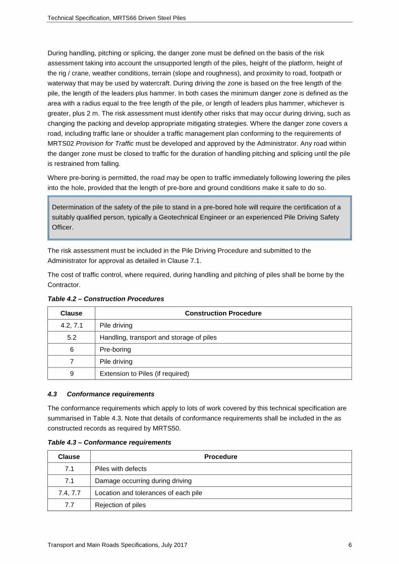
During handling, pitching or splicing, the danger zone must be defined on the basis of the risk assessment taking into account the unsupported length of the piles, height of the platform, height of the rig / crane, weather conditions, terrain (slope and roughness), and proximity to road, footpath or waterway that may be used by watercraft. During driving the zone is based on the free length of the pile, the length of the leaders plus hammer. In both cases the minimum danger zone is defined as the area with a radius equal to the free length of the pile, or length of leaders plus hammer, whichever is greater, plus 2 m. The risk assessment must identify other risks that may occur during driving, such as changing the packing and develop appropriate mitigating strategies. Where the danger zone covers a road, including traffic lane or shoulder a traffic management plan conforming to the requirements of MRTS02 Provision for Traffic must be developed and approved by the Administrator. Any road within the danger zone must be closed to traffic for the duration of handling pitching and splicing until the pile is restrained from falling.
Where pre-boring is permitted, the road may be open to traffic immediately following lowering the piles into the hole, provided that the length of pre-bore and ground conditions make it safe to do so.
Determination of the safety of the pile to stand in a pre-bored hole will require the certification of a suitably qualified person, typically a Geotechnical Engineer or an experienced Pile Driving Safety Officer.
The risk assessment must be included in the Pile Driving Procedure and submitted to the Administrator for approval as detailed in Clause 7.1.
The cost of traffic control, where required, during handling and pitching of piles shall be borne by the Contractor.
Table 4.2 – Construction Procedures
Clause Construction Procedure
4.2, 7.1 Pile driving
5.2 Handling, transport and storage of piles
6 Pre-boring
7 Pile driving
9 Extension to Piles (if required)
4.3 Conformance requirements
The conformance requirements which apply to lots of work covered by this technical specification are summarised in Table 4.3. Note that details of conformance requirements shall be included in the as constructed records as required by MRTS50.
Table 4.3 – Conformance requirements
Clause Procedure
7.1 Piles with defects
7.1 Damage occurring during driving
7.4, 7.7 Location and tolerances of each pile
7.7 Rejection of piles

Technical Specification, MRTS66 Driven Steel Piles
Transport and Main Roads Specifications, July 2017 7
5 Steel piles
5.1 Requirements for steel piles
5.1.1 General
Steel used in piles shall comply with the requirements of the relevant AS/NZS standards referenced in Table 3 and to the section sizes and mass per unit length as shown in the Drawings. Materials test certificates traceable to all steel piles shall be forwarded to the Administrator not less than 12 working days after the delivery of these items to site. Milestone The Materials Test Certificates shall demonstrate conformance to the Standard. Note copies of the Materials Test Certificates shall be included in the as constructed records as required by MRTS50.
Where steel piles are fabricated, for example spirally wound tube piles, these piles shall be fabricated by a departmental registered supplier to MRTS78 Fabrication of Structural Steelwork, see also Clause 1.
5.1.2 Dimensional tolerances
Steel piles shall be supplied within the following tolerances:
a) The length of the pile shall not be less than the gross length as shown in the Drawings
b) The squareness of the ends of the piles shall be such that the surface at the driving end shall not depart from the true cross-section by more than 2 mm, and
c) The lateral bow shall not exceed 0.0007 of the gross length of the pile.
5.1.3 Supplied lengths
Steel piles shall, where possible, be supplied in single (un-spliced) lengths as shown in the Drawings. Spliced lengths shall be accepted only if the specified gross length exceeds the maximum single length for the section size as supplied by the mill, in which case the splicing shall be in accordance with the requirements of Clause 9. In exceptional circumstances piles made up of multiple short lengths spliced together may be used.
Exceptional circumstances would include situations where the driving head room is limited and piles must be spliced from short lengths. An exceptional circumstance does not include a situation where the Contractor elects to “manufacture” a pile from short lengths for their convenience for any reason.
5.1.4 Hot-dipped galvanising
Where piles are required to be galvanised they shall be hot-dipped galvanised in accordance with the requirements of AS/NZS 4680. The average coating mass shall be not less than 600 g/m².
5.2 Transport, handling and storage
5.2.1 General
The Contractor shall assess the route for transport of piles and, in its submission to the Administrator in accordance with Clauses 4.1 and 4.2, shall include full details of the transport arrangements, including means of limiting torsional forces on the piles during transport to prevent torsional cracking.
Technical Specification, MRTS66 Driven Steel Piles
Transport and Main Roads Specifications, July 2017 8
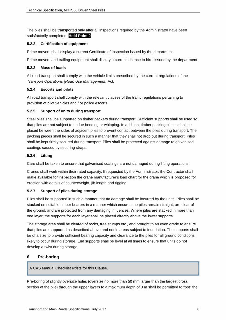
The piles shall be transported only after all inspections required by the Administrator have been satisfactorily completed. Hold Point 2
5.2.2 Certification of equipment
Prime movers shall display a current Certificate of Inspection issued by the department.
Prime movers and trailing equipment shall display a current Licence to hire, issued by the department.
5.2.3 Mass of loads
All road transport shall comply with the vehicle limits prescribed by the current regulations of the Transport Operations (Road Use Management) Act.
5.2.4 Escorts and pilots
All road transport shall comply with the relevant clauses of the traffic regulations pertaining to provision of pilot vehicles and / or police escorts.
5.2.5 Support of units during transport
Steel piles shall be supported on timber packers during transport. Sufficient supports shall be used so that piles are not subject to undue bending or whipping. In addition, timber packing pieces shall be placed between the sides of adjacent piles to prevent contact between the piles during transport. The packing pieces shall be secured in such a manner that they shall not drop out during transport. Piles shall be kept firmly secured during transport. Piles shall be protected against damage to galvanised coatings caused by securing straps.
5.2.6 Lifting
Care shall be taken to ensure that galvanised coatings are not damaged during lifting operations.
Cranes shall work within their rated capacity. If requested by the Administrator, the Contractor shall make available for inspection the crane manufacturer's load chart for the crane which is proposed for erection with details of counterweight, jib length and rigging.
5.2.7 Support of piles during storage
Piles shall be supported in such a manner that no damage shall be incurred by the units. Piles shall be stacked on suitable timber bearers in a manner which ensures the piles remain straight, are clear of the ground, and are protected from any damaging influences. Where piles are stacked in more than one layer, the supports for each layer shall be placed directly above the lower supports.
The storage area shall be cleared of rocks, tree stumps etc., and brought to an even grade to ensure that piles are supported as described above and not in areas subject to inundation. The supports shall be of a size to provide sufficient bearing capacity and clearance to the piles for all ground conditions likely to occur during storage. End supports shall be level at all times to ensure that units do not develop a twist during storage.
6 Pre-boring
A CAS Manual Checklist exists for this Clause.
Pre-boring of slightly oversize holes (oversize no more than 50 mm larger than the largest cross section of the pile) through the upper layers to a maximum depth of 3 m shall be permitted to “pot” the

Technical Specification, MRTS66 Driven Steel Piles
Transport and Main Roads Specifications, July 2017 9
pile or to facilitate pitching unless explicitly banned on the Drawings. Note that details of all pre-boring shall be included in the as constructed records as required by MRTS50.
Pre-bored beyond a depth of 3.0 m shall be permitted if shown on the Drawings or approved by the Administrator. Where such pre-boring is proposed by the Contractor but not shown on the Drawings, the Designer must re-assess the effect of pre-boring on the load capacity of the pile. Where moderate or higher strength surface or near surface materials overlies lesser strength material and the design founding material, pre-boring through the moderate or higher strength material may be considered with the approval of both the Administrator and Designer. If the pre-boring (beyond 3 m) is not shown on the Drawings the Designer’s agreement is mandatory.
Where pre-boring below 3.0 m is used and hole size details are not given on the Drawings, the diameter of the drill bit used shall not exceed the maximum cross sectional dimension of the pile less 50 mm. Driving through the length of the undersize hole shall be carried out with caution and with minimal energy input.
For all steel pile sections other than circular sections, the pre-boring shall be backfilled on completion of piling using either granular material or grout up to the surface level.
Note this requirement is not required for prestressed piles (MRTS65). The reason for its inclusion in this Technical Specification is that steel H and I sections (and similar sections) form a hollow which is unlikely to be filled during driving.
For safety reasons, holes shall be sealed with rigidly fixed covers immediately after drilling.
7 Pile driving
7.1 General
A CAS Manual Checklist exists for this Clause.
Details of the proposed pile driving procedure, including handling, pitching, splicing (if required), pile hammer, HSDT procedures and sub-contractor (at least for the required piles as applicable), PM procedures for the last 10 blows, pile cushion material, helmet and other equipment to be employed for this operation, and the risk assessment as required in Clause 4.2 shall be included in the Contractor’s Quality Plan and shall be submitted to the Administrator at least 18 working days prior to the programmed date for commencement of driving. Milestone. Note details of all pile driving, including driving procedures and the quality plan shall be included in the as constructed records as required by MRTS50. Some of this data may be required in real time to permit the Administrator to make decisions.
The Contractor’s Quality Plan may request pre-boring if considered necessary for the Contractor’s mode of operation, or for safety reasons but not shown on the Drawings. Any request for pre-boring must be based on the Contractor’s own assessment of the pile design and the site’s geotechnical conditions. Pre-boring may be considered and may be approved by the Administrator following the Designer’s consent. Pile driving shall not commence until the procedure is approved by the Administrator. Hold Point 3

Technical Specification, MRTS66 Driven Steel Piles
Transport and Main Roads Specifications, July 2017 10
No pile shall be driven unless it has been inspected and approved by the Administrator (or their delegate). Hold Point 4
Any pile exhibiting a defect which may affect its behaviour during driving and / or serviceability or durability in service, shall be rejected and shall not be used in the works. Nonconformance
If at any stage during driving operations the approved procedures are not followed or any damage to the pile occurs, pile driving shall cease until the problem is corrected. Nonconformance
Piles shall be driven only in the presence of the Administrator (or their delegate). Hold Point 5
During driving a log of penetration shall be kept for each pile as detailed in Clause 7.8.
All piles (including piles monitored with a high strain dynamic tester) shall be monitored for at least the last 10 blows using a PM device as detailed in Clause 7.9.
At least 10% of all piles, including at least one pile per pier and abutment and all test piles shall be monitored using a high strain dynamic tester as detailed in Clause 7.10.
All raked piles shall be monitored with a high strain dynamic tester, checked against vertical piles in the same group or structure.
The minimum requirement of 10% for HSDT is often not achievable due to the one per pier or abutment requirement, resulting in a higher frequency of testing. At least 10 piles are required at each pier or abutment for this minimum requirement may be achieved.
Local excavation (if any) shall be completed before driving of piles is commenced. The driving equipment, once set up, shall remain in position until the Administrator approves its removal to another location. Hold Point 6
Ground material forced up between the piles during the driving operation shall be removed by the Contractor.
7.2 Test pile
A CAS Manual Checklist exists for this Clause.
A test pile is any pile designated as a test pile in the contract documents as well as the first pile driven in each pier or abutment and any pile on which a high strain dynamic test is conducted.
Test piles shall be driven at locations shown on the Drawings. Such piles, if approved by the Administrator, shall form part of the permanent structure.
All test piles shall be monitored using both a HSDT for the majority of the drive and a PM for the last 10 blows of the drive.
7.3 Changes in founding level
A CAS Manual Checklist exists for this Clause.

Technical Specification, MRTS66 Driven Steel Piles
Transport and Main Roads Specifications, July 2017 11
If as a result of information gained from the driving of test piles (or any other piles), the Administrator determines with the agreement of the Designer that changes to the founding level shown on the Drawings are necessary, the Contractor shall be notified of such changes. Notification shall be in writing at the earliest possible time.
7.4 Location and tolerances
A CAS Manual Checklist exists for this Clause.
Piles shall be located in the positions shown on the Drawings within the following tolerances:
a) the maximum lateral displacement of the pile head from its correct position shall be 75 mm, and
b) the maximum deviation from the specified rake shall be 20 mm per metre.
The Contractor shall make all efforts to drive the piles within the tolerances specified above. If the above tolerances are exceeded, the Contractor shall carry out any remedial measures required so that the geometric location of the headstock can be achieved without compromising any other design aspect of the bridge. Nonconformance. Piles shall not be forcibly realigned or sprung into tolerance. Prior to the commencement of the remedial measures, the Contractor shall submit a certified design for the remedial measures. The remedial measures shall not be used until approved by the Administrator Hold Point 7.
7.5 Pile hammer
7.5.1 General
Piles shall be driven using either a conforming hammer equivalent to the design hammer as nominated in Clause 1 of Annexure MRTS66.1 or an Alternative hammer in accordance with Clause 7.5.3 (an alternative hammer). The actual hammer used is termed the “job hammer”. Note that details of the pile hammers as used for all pile driving shall be included in the as constructed records as required by MRTS50.
7.5.2 Conforming and Design hammer
A CAS Manual Checklist exists for this Clause.
The design hammer is the hammer the designer has nominated for use during the contract having cognisance of the geotechnical conditions existing of the site, the mass of the piles to be driven and the required capacity of the piles. The details of the design hammer are shown in Clause 1 of Annexure MRTS66.1. A conforming hammer is one which meets or exceeds the capability of the Design hammer in terms of falling mass, drop height and rated energy and it input energy can be adjusted to consistently achieve a similar energy input as the design hammer after all relevant losses have been accounted for and also conforms to the requirements of Table 7.5.2.
For heavy hammers, of mass over 125% of the design hammer, it is critical that the input energy can be accurately controlled to give an equivalent energy input as the design hammer. When using a heavy hammer, the input energy should be adjusted to give a typical driving set of 5 mm to 10 mm. Provided this can be achieved there is no upper limit on the mass of a heavy hammer.
The drop of the hammer or of the ram shall not exceed 2 m.
Technical Specification, MRTS66 Driven Steel Piles
Transport and Main Roads Specifications, July 2017 12
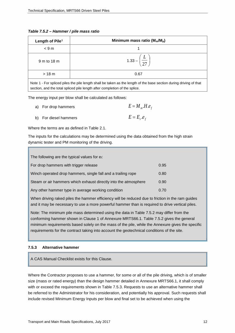
Table 7.5.2 – Hammer / pile mass ratio
Length of Pile¹ Minimum mass ratio (Mm/Mp)
< 9 m 1
9 m to 18 m 1.33 –
27L
> 18 m 0.67
Note 1 - For spliced piles the pile length shall be taken as the length of the base section during driving of that section, and the total spliced pile length after completion of the splice.
The energy input per blow shall be calculated as follows:
a) For drop hammers fm eHME ..=
b) For diesel hammers fr eEE .=
Where the terms are as defined in Table 2.1.
The inputs for the calculations may be determined using the data obtained from the high strain dynamic tester and PM monitoring of the driving.
The following are the typical values for ef:
For drop hammers with trigger release 0.95
Winch operated drop hammers, single fall and a trailing rope 0.80
Steam or air hammers which exhaust directly into the atmosphere 0.90
Any other hammer type in average working condition 0.70
When driving raked piles the hammer efficiency will be reduced due to friction in the ram guides and it may be necessary to use a more powerful hammer than is required to drive vertical piles.
Note: The minimum pile mass determined using the data in Table 7.5.2 may differ from the conforming hammer shown in Clause 1 of Annexure MRTS66.1. Table 7.5.2 gives the general minimum requirements based solely on the mass of the pile, while the Annexure gives the specific requirements for the contract taking into account the geotechnical conditions of the site.
7.5.3 Alternative hammer
A CAS Manual Checklist exists for this Clause.
Where the Contractor proposes to use a hammer, for some or all of the pile driving, which is of smaller size (mass or rated energy) than the design hammer detailed in Annexure MRTS66.1, it shall comply with or exceed the requirements shown in Table 7.5.3. Requests to use an alternative hammer shall be referred to the Administrator for his consideration, and potentially his approval. Such requests shall include revised Minimum Energy Inputs per blow and final set to be achieved when using the

Technical Specification, MRTS66 Driven Steel Piles
Transport and Main Roads Specifications, July 2017 13
proposed hammer. Note that this final set shall not be less than 2.5 mm/blow, and the drop height shall not exceed 2.0 m.
Essentially a revised Annexure MRTS66.1 should be provided for the new hammer, however the following data must not be revised to suit the alternative hammer details:
• Clause 3 - Required Minimum Ultimate Capacity
• Clause 4 – all
• Clause 5 should generally not be changed but in some circumstances, depending on the content of Clause 5 it may require amendment.
Since the 2.5 mm/blow is defined as nominal refusal, irrespective of hammer size, a set less than this is unacceptable. Approval should not be given to use a hammer which would require a final set of less than 2.5 mm/blow.
Approval should not be given to a hammer not conforming to Table 7.5.3, or one requiring a drop height of 2.0 m or more.
Table 7.5.3 – Hammer/Pile mass ratio
Length of Pile¹ Minimum mass ratio (Mm/Mp)
< 9 m 0.75
9 m to 18 m 1 -
36L
> 18 m 0.5
Note 1 - For spliced piles the pile length shall be taken as the length of the base section during driving of that section, and the total spliced pile length after completion of the splice.
At least two test piles shall be driven at the first pier/abutment piled and at least one test pile at each subsequent abutment or pier. The dynamic analysis, which shall comply with the requirements of MRTS68 is required to demonstrate that:
a) the pile capacity has been achieved
b) the pile has not been damaged
c) the tension wave stresses in the pile are less than 0.6 times the initial prestress in the pile, and
d) the Pile Monitoring results and the dynamic analysis results correlate.
Generally the same hammer as used for a test pile shall be used for normal production piles. Where a hammer change is required a further test pile shall be driven for each change in hammer. Prior to approval of an alternative hammer (or any hammer other than a conforming hammer), the Administrator shall obtain from the Contractor a table of revised sets for the pile driving using the alternative hammer (Clause 3 of Annexure MRTS66.1).

Technical Specification, MRTS66 Driven Steel Piles
Transport and Main Roads Specifications, July 2017 14
Due to the uncertainty in calculating the effective energy of hammers which imparting extra energy, it is imperative that the final set of the all piles driven using such hammers are monitored using a PM. They may also require a higher frequency of dynamic testing (high strain) particularly initially.
7.6 Pile helmet
A CAS Manual Checklist exists for this Clause.
The pile helmet shall be of substantial steel construction and cylindrical in shape where it overlaps the side of the pile so as to permit the pile to rotate freely about its vertical axis. The helmet shall be loose fitting on the pile head, with no more than 15 mm uniform clearance to the outermost points around the periphery of the pile.
The helmet shall slide in and be guided by the leaders of the pile frame and shall remain in contact over the whole area of the top of the pile under its own weight.
The helmet shall have a steel diaphragm fitted at approximately mid height.
Between the steel diaphragm and the pile head there shall be placed an approved cushion of pine, natural-fibre rope, rubber, plywood or other approved material [refer Hold Point 1]. On top of the diaphragm, and fitting tightly into the helmet, there shall be placed a hardwood block approximately 300 mm long, or an approved packing of equivalent stiffness [refer Hold Point 1]. The timber block (if used) shall have the grain parallel to the axis of the pile.
7.7 Driving procedure
A CAS Manual Checklist exists for this Clause.
To avoid damage by bending, the piles shall be driven from a fixed frame having sufficient rigidity to ensure accuracy of driving and freedom from bending of the pile under all conditions of tides, stream flow, hammer action or other disturbance which may occur during the driving. Flying leaders shall not be used unless the Contractor can demonstrate to the satisfaction of both the Administrator and the Director (Bridge Construction Maintenance and Asset Management) that the system used for such leaders will only transmit axial loads to the pile. Use of flying leaders shall not continue if piles deviate from vertical or if piles start to show damage during driving. Note that details of all the driving procedure shall be included in the as constructed records as required by MRTS50.
Damage to the head of the pile is often evidence that the hammer is not sitting correctly on the pile.
The force of the hammer blow shall be directed along the longitudinal axis of the pile. Care shall be taken to avoid inducing torsional stresses into the pile by ensuring that the pile is not restrained against rotation about its longitudinal axis.
Piles shall be guided and held on line particularly during the initial stages of driving. Shortly after commencement of driving and at regular intervals throughout the driving operation, checks shall be

Technical Specification, MRTS66 Driven Steel Piles
Transport and Main Roads Specifications, July 2017 15
made to ensure that the pile frame does not exert any undue lateral force on the pile. Attempts to correct any tendency for the pile to run off line by the application of significant horizontal restraint shall not be permitted. If the indications are that a driven pile shall terminate outside the specified tolerances, driving operations on that pile shall cease (see also Clause 7.4).
Particular care shall be exercised when driving into pre-bored holes as detailed in Clause 6.
A pile shall be rejected when:
a) In the opinion of the Administrator, a pile is damaged during driving and the damage is materially detrimental to the strength or durability of the pile. Nonconformance
b) The pile is positioned out of tolerance. Nonconformance
c) When either PM or HSDT monitoring indicates that the pile is damaged.
If, in the Administrators opinion, the damage is such that the pile can be repaired rather than rejected the cost of the required repairs shall be borne by the Contractor.
The Administrator's decision to reject or repair a pile shall be final.
In order to avoid damage to the piles by tension stress waves caused by the impact of the hammer, driving shall commence with an initial energy input limited to the minimum energy which can be achieved for the conforming hammer. The energy input shall be gradually increased incrementally as the pile resistance increases. Driving shall then continue to final set with increasing energy input and decreasing penetration per blow, with the provision that the maximum penetration of 25 mm per blow shall not be exceeded. If penetration exceeds 25 mm per blow, the driving energy shall be reduced to such an extent that 25 mm set is again attained.
Damage to piles is not generally caused by using even a grossly oversize hammer. Likely causes of pile damage are, in order of likelihood, (a) hammer and pile not properly aligned (b) excessive drop height and (c) driving into a pre, bored hole using excessive energy.
Driving with a diesel hammer shall commence with the fuel throttled to the minimum required for the hammer to fire.
7.8 Pile driving log
During driving the Contractor shall keep a log of progress of the drive showing the number of blows (including hammer input energy or drop height) per 0.25 m of penetration, as detailed in Clause 12, item 2. Where the piling Contractor uses an automatic system (generally hard wired into the piling rig) this will suffice provided it gives at least the same information, Where a pile is tested by a HSDT then this will also suffice provided specifically the depth of penetration (at not greater than 0.25 m intervals) is recorded by the system. Note that the pile driving logs shall be included in the as constructed records as required by MRTS50.
7.9 Monitoring of pile driving (PM)
A CAS Manual Checklist exists for this Clause.

Technical Specification, MRTS66 Driven Steel Piles
Transport and Main Roads Specifications, July 2017 16
PM testing shall be undertaken on all piles for at least the last 10 blows of the drive. Note all the monitoring records shall be included in the as constructed records as required by MRTS50. Further, this data may be required in real time to permit the Administrator to make decisions.
Where a piles has been tested using High Strain Dynamic Testing (HSDT) the standard PM testing for the last 10 blows shall also be undertaken and these results correlated with the HSDT data. The results of the PM information shall be correlated with HSDT to determine the input parameters for calculation of capacity using the Hiley formula as shown in Clause 7.11.
The Contractor shall supply complete digital and paper records of pile driving (including all high strain dynamic tester and PM records) and pile hammer details to the Administrator in accordance with MRTS50.
Where the PM monitoring indicates that the pile is damaged this information shall be immediately reported to the Administrator. See also Clause 7.7.
A number of proprietary PM systems exist. Some are offset from the pile some are hard wired into the pile frame. Provided the system records all the required parameters, the specific system is the Contractor’s decision.
7.10 High Strain dynamic testing (HSDT)
High strain dynamic testing of piles using wave equation analysis shall be used to confirm the ultimate pile capacity at the positions nominated in MRTS68 and MRTS68.1. The procedure for HSDT testing shall be in accordance with the requirements of MRTS68. Note that records of all HSDT shall be included in the as constructed records as required by MRTS50. Further, this data may be required in real time to permit the Administrator to make decisions.
Where the HSDT testing indicates that the pile is damaged this information shall be immediately reported to the Administrator. See also Clause 7.7.
7.11 Pile capacity and pile set
A CAS Manual Checklist exists for this Clause.
The minimum ultimate capacity for the various piles is given in Clause 3 of Annexure MRTS66.1.
The values of final set per blow given in Clause 3 of Annexure MRTS66.1 should be calculated using the job hammer the energy stated in Clause 3 of Annexure MRTS66.1 and the use of a minimum amount of cushion material sufficient only to prevent damage to the pile during driving. If the Annexure uses a hammer other than the job hammer it shall be recalculated to conform to the job hammer requirements. See also Clause 7.5.
Required values of final set shall be calculated using the following version of the Hiley Formula, using the actual equipment details, coefficients for temporary compressions and efficiency of each blow as measured on site.
C5.0RE
MMM)]MM(eM[
9800Spfm
pf2
m −×++
++×=

Technical Specification, MRTS66 Driven Steel Piles
Transport and Main Roads Specifications, July 2017 17
Where the terms are as defined in Table 2.1
The following are the expected typical values for “e” in the Hiley equation.
E = 0.25 for 300 mm hardwood packing (acting alone), or
E = 0.40 for 100 mm of Novasteen (acting alone)
If the monitoring device used determines the value of “e” then this value may be used rather than the assumed values as above.
7.12 Pile penetration
Piles shall be driven until both the calculated set and the minimum penetration (this should be shown on the Drawings or in Clauses 3 and 4 of Annexure MRTS66.1,) have been attained. If, the calculated set has been achieved but, the pile is not yet at the specified founding level, driving shall continue until either the specified founding level or nominal refusal has been achieved, whichever is attained first. Nominal refusal shall be deemed to be the situation where 25 mm total penetration is achieved for 10 blows using the specified energy of the conforming hammer. Where the job hammer is an alternative hammer, set and nominal refusal values shall be recalculated to suite the parameters of the job hammer. Where set or design founding level are not achieved then one or more of Clauses 7.12.1 to 7.12.3 become operative.
Driving shall not continue when the average set over a 250 mm interval is less than that of nominal refusal, which is 2.5 mm per blow.
The intent of the 250 mm limit is to avoid a situation where a very thin hard band exists which could be piled through. The 250 mm limit should not be enforced as the minimum over which refusal shall be determined, that is, only 10 blows may be adequate to define nominal refusal in a situation where a pile is refusing on hard rock. Engineering judgement needs to be used.
In all cases, a pile shall not be terminated at a level more than 1.0 m above the founding level shown on the Drawings, or above the minimum penetration level as shown on the Drawings or Annexure MRTS66.1, without the written approval of the Designer and Administrator. Note that records all final pile tip levels shall be included in the as constructed records as required by MRTS50.
The following options need to be considered when contemplating changing the founding level of piles.
If set is achieved above design founding level, do you stop at that level or continue driving to the design founding level or to nominal refusal whichever occurred first? Note that there may be contractual implications of the decisions as well as geotechnical issues, for example; disposal of unused length of pile, the quantum of pile driving will be reduced, are the head bars long enough or will new head bars be required, is the proposed founding strata adequate, is it underlain by lesser strength material? As a general rule it may be better contractually to drive to nominal refusal or design level, but never at a set of less than nominal refusal of 2.5 mm per blow.
When a pile is driven to design level, and set is achieved, stop driving at the design level.
If the pile reaches design level and set has not been achieved, then if possible, continue driving until set has been reached and then stop. If the pile is driven as far as it can be without the need to

Technical Specification, MRTS66 Driven Steel Piles
Transport and Main Roads Specifications, July 2017 18
extend the pile (for driving), then it may be reasonable to do a restrike. If on restrike set is obtained then stop. If on restrike set is not achieved, a review of the pile design may need to be undertaken.
In regards to extending the pile, if the pile must be extended and then driven this is the worst possible situation in terms of delay to the project. Where a pile only needs to be extended for structural purposes (that is will not be driven further) this is a relatively quick and simple operation.
7.12.1 Piles refuse above minimum penetration level
Where the pile cannot be driven to the minimum penetration level, then driving shall cease and the Designer contacted to determine the issue and for advice. Hold Point 8
When piles are consistently hanging up, it may be prudent to determine the capacity of the pile in the “high” founding level and then reassess the design rather than take extraordinary efforts to achieve penetration. It would be prudent to undertake high strain dynamic tests or PM such piles to ensure damage is not occurring to the piles. When piles hang up the Designer and TMR Structures should be contacted to determine what the issues are at the site.
7.12.2 Piles do not achieve capacity below founding level
If the full length of the pile has been driven and the pile fails to meet the minimum capacity requirements of Clause 3 of Annexure MRTS66.1, the Contractor shall continue driving using a follower until the required pile capacity is achieved. The pile shall then be extended using the same section as the original pile segment.
The Contractor may request a restrike (Clause 7.12.3), as detailed below, at any stage when driving below founding level. If the restrike is successful (set has been achieved) then the pile shall be accepted, otherwise further driving as detailed above shall be undertaken.
If the pile has been driven using a follower and cannot be practically driven further and still has not reached the required capacity, then piling shall cease and the Designer contacted to determine the issue and for advice.
7.12.3 Restrike
A CAS Manual Checklist exists for this Clause.
If the design pile penetration has been reached or exceeded, but set not yet attained, the Contractor may request a restrike of the pile. In this case piling shall cease for at least 12 hours, and the pile restruck using the nominated driving energy as detailed in Clause 3 of Annexure MRTS66.1 for a minimum of a total of 15 blows. The set shall then be determined over the last 10 of these blows. If the required set is achieved the pile shall be accepted. Note that records of all restrikes shall be included in the as constructed records as required by MRTS50.
7.13 Follower
A CAS Manual Checklist exists for this Clause.

Technical Specification, MRTS66 Driven Steel Piles
Transport and Main Roads Specifications, July 2017 19
A follower shall only be used in the circumstances outlined in Clause 7.12.2, it shall not be used simply for the convenience of the Contractor.
Interface packing shall be used between the pile and the follower so as to ensure a uniform transfer of driving stresses across the interface.
A sleeve or other device shall be used to ensure alignment of the follower with the pile during driving.
The required set shall be recalculated to include the effects of the follower and the interface packing.
Where circumstances warrant the use of a follower, it shall be employed with the minimum of interruption to the driving sequence. Nevertheless, some tightening of the previously driven portion of the pile may occur as a result of the delay and it may be necessary to continue driving for some time with full energy input and minimal set until the pile again loosens sufficiently to continue penetrating at the same rate as before the interruption.
8 Trimming of pile head
Following completion of driving, the pile head shall be trimmed by cutting off the top of the pile to the correct level as shown in the Drawings.
9 Extension to piles
Extensions to piles, including splices, shall proceed only after the weld procedure specification has been approved by the Administrator. Hold Point 9. Note records of all pile extensions shall be included in the as constructed records as required by MRTS50.
Extensions to piles shall be made as follows:
a) The extension section shall have a section size and mass per unit length equal to that of the previously driven section
b) The extension section shall be aligned accurately with the previously driven section of the pile
c) The joint edges shall be prepared and the sections welded together using full penetration double vee butt welds, all in accordance with AS/NZS 1554.1, and
d) The welded joint shall be protected with a cold galvanising paint which is compatible with the original coating and registered by the department (refer Clause 1). The paint shall be applied in accordance with the manufacturer's recommendations.
Under no circumstances shall more than two splices be located in any 6 m section of pile, unless exceptional circumstances exist.
Exceptional circumstances would include situations where the driving head room is limited and piles must be spliced from short lengths. An exceptional circumstance does not include a situation where the Contractor elects to “manufacture” a pile from short lengths for their convenience for any reason.
Driving shall not recommence until the welded splice, including the cured protection coating, has been inspected and approved by the Administrator. Hold Point 10

Technical Specification, MRTS66 Driven Steel Piles
Transport and Main Roads Specifications, July 2017 20
10 Bond bars
After the trimming of the pile head is complete, Grade 500N bond bars shall be welded to the pile head.
The size of the bond bars and the size of the welds shall be as shown in the Drawings.
Welding shall be carried out in accordance with AS/NZS 1554.1.
11 Approvals of changes
A CAS Manual Checklist exists for this Clause.
Since formal approval is required for a number of changes from the as designed requirements, the process to be followed is as described below. Note details of all approved changes shall be included in the as constructed records as required by MRTS50.
The Contractor shall request from the Administrator approval of a change to the specification or design. The Administrator may consult widely (including but not limited to the Designer or Transport and Main Roads Structures section, or Transport and Main Roads generally) to help in resolving any issue. Potential areas of change include (but not limited to) changes in hammer details, founding levels, pre-bore details which may relate to all piles or specific piles. The Administrator may request information or a recommendation from others, for example the Designer, to aid in his acceptance or rejection process.
The Designer may recommend or reject all or some of the requested changes or accept some or all. If any change are accepted as a result of a Contractors request, (for example to Annexure MRTS66.1 to change hammer details), the Contractor shall submit a draft revised completed (and certified by an RPEQ) Annexure with the request. This revised Annexure will then become “the” Annexure for purposes of part or all of the Technical Specification once the request has been approved by the Administrator. Multiple changes may require multiple cycles of this procedure.
A Contractor may request that a different hammer is to be used for all driving (a global request applying for all piles), or that a different hammer is used for a specified number of piles, for example; all abutment piles or piles on say Pier 3. Similarly with founding levels, they may relate to one or more piles or positions.
Where a request involves a change in founding level of less than 1.0 m, then this should be treated as a variation to be approved by the Administrator, rather than a change to the Technical Specification. See also the comments regarding the accuracy of the design founding level in Table 2.1
12 As constructed records
Table 12 summarises the details of the requirements for As constructed records found in this Technical Specification. Further details of the requirements for As Constructed records can be found in MRTS50 Specific Quality System Requirements.

Technical Specification, MRTS66 Driven Steel Piles
Transport and Main Roads Specifications, July 2017 21
Table 12 – Details of As Constructed
Clause Details
4.1 Hold points and Witness points, including details of the release
4.2 Details of construction procedures
4.3 Details of conformance requirements
5.1.1 Materials test certificates for all steel
6 Details of pre-boring for each pile
7.1, 7.7 Details of pile driving
7.5.1 Details of the pile hammer used and maximum drop, for each pile
7.8 Pile driving log for each pile
7.9 Records of PM for each pile
7.10 Records of HSDT testing for all piles so tested.
7.12 Details of the penetration of each pile
7.12.3 Details of all restrikes including PM records of the restrike
9 Details of all extended piles
11 Details of all approved changes including certification by an RPEQ if required
13 Supplementary requirements
The requirements of MRTS66 Driven Steel Piles are varied by the Supplementary requirements given in Clause 4 of MRTS66.1 Annexure.
