trends in industry applications of cfd for maritime...
TRANSCRIPT
8
Trends in Industry Applications of CFD for Maritime Flows
Milovan Peric, CD-adapco, Nuremberg/Germany, [email protected] Volker Bertram, FutureShip, Hamburg/Germany, [email protected]
Abstract The paper surveys developments in CFD applications for maritime structures (ships, propellers and
offshore structures) over the past decade. Progress is significant in integrating the process chain,
particularly more automated model generation. Increased hardware power and progress in various
aspects of the flow solvers allow more sophisticated applications and wider scope of applications.
Selected examples taken from industry and research applications show the increasing importance of
CFD in earlier design stages.
1. Introduction
Computational fluid dynamics (CFD) denotes collectively techniques solving equations describing the physics of flows. We interpret “CFD” here as techniques solving Euler, RANSE (Reynolds Averaged Navier-Stokes Equations) or Navier-Stokes equations, using field methods, Ferziger and Peric
(2010), Bertram (2012).
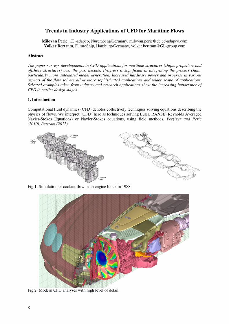
Fig.1: Simulation of coolant flow in an engine block in 1988
Fig.2: Modern CFD analyses with high level of detail

9
CFD became a research field in the late 1960s. First commercial CFD software appeared in the 1980s including codes like PHOENICS, FLUENT, STAR-CD, CFX, TASCFLOW, and FLOW3D. By today’s standard, these codes were very limited in terms of complexity of geometry and physics. Applications were severely limited by the available computer power in those days. An example may illustrate how CFD progressed over the decades. In 1988, an advanced CFD application in the automotive industry investigated the coolant flow in an engine block using some 10000s of cells, Fig.1. Two decades later, the progress in CFD allows the simulation of fluid and heat flows in engine compartments with some 700 parts and typically around 30 million control volumes, even 100 millions for detailed studies, Fig.2. However, the increase in grid size and associated capturing of geometry and flow details is only one aspect of the CFD developments of the past decades. It is a perhaps surprising fact that computational times have increased over the years. The demand for ever more ambitious simulations (in terms of cell count and flow complexity) thus outpaced the exponential growth in computational power. Despite the increase in average computational time, CFD projects today are often noticeably shorter than they were two decades ago. This is due to less frequent re-modelling and re-analyses, and also generally significantly reduced time in pre-processing. The reason is that CFD tools have become more user-friendly, Fig.3. This is perhaps best illustrated in the case of integrated design environments, e.g. the Friendship Framework, Abt and Harries (2007). The integrated design environment combines freeform hull description using parametric modelling, interfaces to most modern CFD solvers including STAR-CCM+, several optimization algorithms, and software to handle process management and user interface. The design engineer can then work on simulation driven designs (e.g. of hulls, appendages or propellers) with one integrated user interface from model generation to post-processing. The user-friendliness of this approach has certainly lowered thresholds in using CFD for designers.
Fig.3: Integrated design environments allow simulation driven designs There are many more aspects that have in sum advanced the wide acceptance of simulation first as a design and more recently as an optimisation tool in industry. The most important among these aspects are:
10
• The ability to handle complex geometry with all relevant details, including moving parts; • Efficient simulation process (from geometry to solution, parametric studies, optimization
studies, user interface...); • Adequate modelling of turbulence, free-surface effects and cavitation; • Coupled simulation of flow and flow-induced motion (and in some cases deformation) of
bodies. These will be discussed in more detail in the following. 2. Key aspects of progress in CFD for maritime flows 2.1. Handling of complex geometry During the past decade, the ability to handle complex geometry with all relevant details has been greatly improved. Components that have contributed to this trend include:
• Tools for automatic and user-friendly manual repair of CAD models (which are often imperfect) have been developed; IGES files coming from designers frequently feature overlaps and gaps. These are not problematic for design purposes (e.g. volume computations are required for ship stability and capacity), but frequently lead to fatal errors for CFD grid generation.
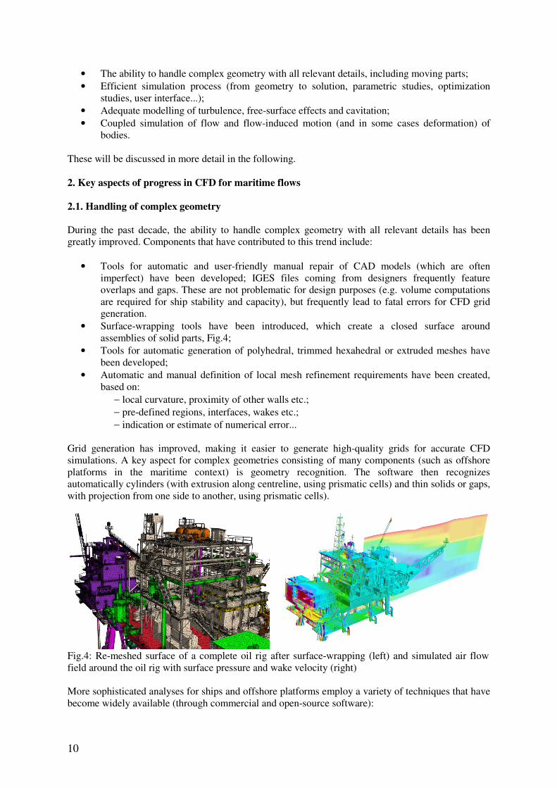
• Surface-wrapping tools have been introduced, which create a closed surface around assemblies of solid parts, Fig.4;
• Tools for automatic generation of polyhedral, trimmed hexahedral or extruded meshes have been developed;
• Automatic and manual definition of local mesh refinement requirements have been created, based on:
− local curvature, proximity of other walls etc.; − pre-defined regions, interfaces, wakes etc.; − indication or estimate of numerical error...
Grid generation has improved, making it easier to generate high-quality grids for accurate CFD simulations. A key aspect for complex geometries consisting of many components (such as offshore platforms in the maritime context) is geometry recognition. The software then recognizes automatically cylinders (with extrusion along centreline, using prismatic cells) and thin solids or gaps, with projection from one side to another, using prismatic cells).
Fig.4: Re-meshed surface of a complete oil rig after surface-wrapping (left) and simulated air flow field around the oil rig with surface pressure and wake velocity (right) More sophisticated analyses for ships and offshore platforms employ a variety of techniques that have become widely available (through commercial and open-source software):

11
• The ability to handle moving parts using morphing, sliding interfaces or overlapping grids
(e.g. propellers, rudders etc.); • The ability to model complete systems rather than single parts (e.g. ship with all appendages,
Fig.5, complete oil platforms, etc.); • The ability to easily replace geometry and perform a new simulation (automation of
simulation process; e.g. ship with and without a wake equalizing nozzle, Fig.6).
Fig.5: Ship with rudder and propeller illustrating the trend towards modeling complete systems
Fig.6: Analyses of ship without (left) and with (right) nozzle to assess quantitatively the effect of the nozzle at full scale before deciding on the investment; block-structured approach allows exchanging block with nozzle and rapid re-analyses 2.2. Turbulence modelling
Turbulence modelling was in the “villain” of the 1980s and 1990s. Unsatisfactory results were often blamed on turbulence modelling. Several dedicated validation workshops have shed more light on adequacy and inadequacy of turbulence modelling for marine flows, Figs.7-9. For most applications in industry practice, the importance of turbulence modelling is over-rated. Turbulence models play a significant role on the flow structures and resulting resistance of bare hulls, as investigated in most validation studies. However, the propeller behind the ship dominates flows and reduces the effect and importance of the turbulence model. Since only the propulsion case is relevant for industry, turbu-lence modelling is thus of lesser importance for classical resistance & propulsion applications. For seakeeping, the free-surface effects dominate anyway. This leaves manoeuvring and propeller flow investigations as areas of application where turbulence modelling remains an important issue. For most applications in industry, the standard k-ε or k-ω turbulence models are adequate. In order to predict secondary flows better, more sophisticated models are needed. The Reynolds-stress model

12
(RSM) is then frequently a popular and appropriate option. A special turbulence model is needed to predict transition from laminar to turbulent flow, e.g. when predicting resistance of a competitive sailing yacht. Such models are also available. For predicting noise sources, wall vibration etc., large-eddy-simulation (LES) or detached eddy simulation (DES) type of analyses with special subgrid-scale turbulence models are used. These are rather subject to research than state of the art in industry. The CFD expert needs to select the most appropriate model for any given analysis task (and may decide not to use any turbulence modelling…).
Fig.7: RSM turbulence model for KLVCC test case; wind tunnel test (top) and CFD (bottom)
Fig.8: Measured and predicted velocity profiles Fig.9: Resistance prediction for KLVCC without
free surface, using RSM turbulence model

13
2.3. Modelling of free-surface effects
Ships operate at the interface of water and air. Correspondingly, free-surface flows are of prime inter-est for naval architects. The wave resistance of a ship is one example, as this component of the total resistance offers the largest improvement potential for small to moderate changes in the hull shape. Other applications of free-surface flows are seakeeping (interaction with waves), slamming (external impact due to waves) and sloshing (internal impact in partially filled tanks). Interface-capturing meth-ods (volume of fluid, two-phase flow, level set, etc) allow the simulation of highly nonlinear free-surface flows. Where the two fluids (typically water and air) are not expected to mix, a sharp interface (within one control volume) can be obtained, Fig.10. This minimizes numerical mixing. Resulting quantities of engineering interest, e.g. induced loads in tanks with sloshing, are so well predicted that such simulations are widely accepted by classification societies for load determination in strength analyses. Arbitrary free-surface deformation, even trapped gas bubbles or detaching droplets are ade-quately accounted for, as gravity and surface tension effects are included. If deemed necessary, both gas and liquid can be modelled as compressible fluids. Phase change models (cavitation, boiling) may be integrated into this method to allow more complex phenomena to be modelled. Despite the signifi-cant progress in free-surface modelling, research continues in this field, as the modelling of breaking waves can still be improved in terms of air mixing and turbulence interaction with the free surface. In regions, where in reality white foam appears (mix of air and water), current CFD simulations show smeared surfaces, Fig.12, and predict the propagation of these waves less accurately.
Fig.10: Free-surface resolution within one cell after 100 periods (= 20 min in corresponding real time)
Fig.11: Measured and computed pressures at one point in the tank
Fig.12: Computed wave field around DTMB 5415 (destroyer geometry); smeared surface at bow and stern where waves break, sharp surface elsewhere
14
2.4. Cavitation modelling
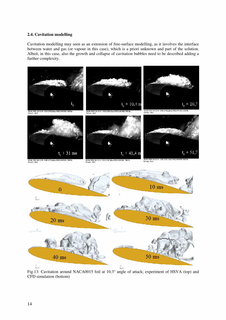
Cavitation modelling may seen as an extension of free-surface modelling, as it involves the interface between water and gas (or vapour in this case), which is a priori unknown and part of the solution. Albeit, in this case, also the growth and collapse of cavitation bubbles need to be described adding a further complexity.
Fig.13: Cavitation around NACA0015 foil at 10.3° angle of attack; experiment of HSVA (top) and CFD simulation (bottom)
15
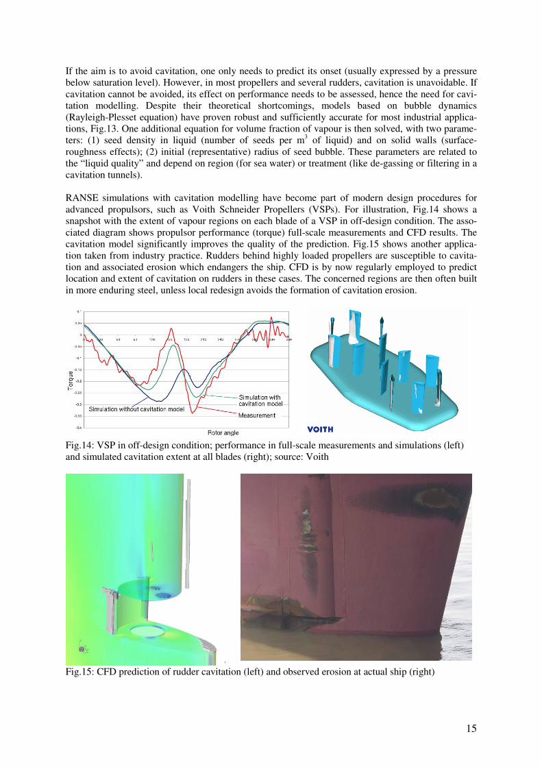
If the aim is to avoid cavitation, one only needs to predict its onset (usually expressed by a pressure below saturation level). However, in most propellers and several rudders, cavitation is unavoidable. If cavitation cannot be avoided, its effect on performance needs to be assessed, hence the need for cavi-tation modelling. Despite their theoretical shortcomings, models based on bubble dynamics (Rayleigh-Plesset equation) have proven robust and sufficiently accurate for most industrial applica-tions, Fig.13. One additional equation for volume fraction of vapour is then solved, with two parame-ters: (1) seed density in liquid (number of seeds per m3 of liquid) and on solid walls (surface-roughness effects); (2) initial (representative) radius of seed bubble. These parameters are related to the “liquid quality” and depend on region (for sea water) or treatment (like de-gassing or filtering in a cavitation tunnels). RANSE simulations with cavitation modelling have become part of modern design procedures for advanced propulsors, such as Voith Schneider Propellers (VSPs). For illustration, Fig.14 shows a snapshot with the extent of vapour regions on each blade of a VSP in off-design condition. The asso-ciated diagram shows propulsor performance (torque) full-scale measurements and CFD results. The cavitation model significantly improves the quality of the prediction. Fig.15 shows another applica-tion taken from industry practice. Rudders behind highly loaded propellers are susceptible to cavita-tion and associated erosion which endangers the ship. CFD is by now regularly employed to predict location and extent of cavitation on rudders in these cases. The concerned regions are then often built in more enduring steel, unless local redesign avoids the formation of cavitation erosion.
Fig.14: VSP in off-design condition; performance in full-scale measurements and simulations (left) and simulated cavitation extent at all blades (right); source: Voith
Fig.15: CFD prediction of rudder cavitation (left) and observed erosion at actual ship (right)

16
2.5. Motion of floating bodies For a variety of seakeeping problems, implicitly coupled simulations of flows and flow-induced mo-tions of floating bodies (ships or offshore structures) are desired. These simulations should be implicit, as implicit simulations pose no restrictions on the time-step size for stability reasons. The time step can be chosen then according to accuracy requirements. Highly nonlinear motions (e.g. launching of free-fall lifeboats with subsequent water entry and resurfacing) are better handled in implicit simula-tions. Such rigid-body motions of freely moving ships have been presented for a variety of applica-tions including many industry projects, e.g. for slamming investigations, Fig.16. The simulations can handle in principle all complexity required in offshore and naval architectural applications, including multi-body configurations moving relative to each other, possible coupling between bodies (via elastic moorings, rigid connections, or flexible links with constraints), inclusion of external forces (e.g. thrusters, mooring, towing), or relative motion of system components (e.g. propellers).
Fig.16: Slamming investigation for a megayacht; CFD snapshot (left) and validation with full-scale measurements (right) 2.6. Fluid-Structure-Interaction (FSI)
Coupled simulation of flow and flow-induced deformation of solid structures have evolved more re-cently for marine applications. FSI is important for relatively soft structures, for very large ships (e.g. whipping and springing, i.e. hydro-elastic vibrations of the ship hull) and offshore structures (like floating airports) as well as for better prediction of impact loads (slamming and sloshing). So far, coupling of RANSE CFD codes and finite-element codes (for the structural analyses) is usually ex-plicit, making the computations inefficient to the point where they are not applicable to most practical problems. Implicit coupling (as already in place for rigid-body motions in waves) is required for ro-bustness and computational efficiency. On the other hand, the structural model can be simplified (e.g. treating the ship as a beam subject to bending and torsion). Such simplified structural models with implicit coupling have already been implemented, e.g. Oberhagemann et al. (2008), Fig.17.
Fig.17: Green water on deck after one slamming event (left); measured and computed accelerations in bow region for a rigid and an elastic ship structure (right)

17
3. Trends Computer hardware continues to become more and more powerful. Highly parallel computing envi-ronments have become affordable even for small and medium enterprises. The appetite grows at least as fast as the more powerful capabilities become available. Higher demands from simulations come in various forms:
• More complete system analysis, with all geometrical details; • More transient simulations (URANS (= unsteady RANS), DES and LES); • Prediction of pressure fluctuation and noise sources (turbulence, cavitation); • More fluid-structure-interaction (slamming, sloshing) and other multi-physics (wind, fire, pol-
lution etc.) applications; • Simulation of full manoeuvring tests (circle, zig-zag, etc.) already in conceptual design; • Simulation of interaction (ship + ice, ship + platform, ship + ship etc.). • More automatic optimization studies...
Of the many developments on the horizon, we select two for illustrative purposes, namely coupling CFD with formal optimization in ship design and coupling CFD in simulators for training and assess-ment purposes. 3.1. Design optimization
Optimization strives to maximize desired features (objectives) subject to constraints. The difficulty in practice lies in the expressing all objectives and constraints in mathematical functions of sufficient accuracy and numerical efficiency, Bertram (2003). This task is often more difficult than it sounds. It requires
• a smart engineer, who is able to model the problem at hand with just the right level of detail and sets up a design search space that is large enough to find significant improvements, yet small enough to allow efficient exploration;
• a tool to help the engineer to convert his model into an efficient optimization process The mathematical algorithm for the actual optimization is secondary. Simulations play a pivotal role as they are used to assess a design, e.g. in terms of required power in fuel efficiency optimizations. Care is needed when changes in candidate designs are small, as then the required accuracy in turn is high. Fortunately, often the task is to find the design that is optimum, rather than an accurate determi-nation of the object function (e.g. required power) for this design. Thus if the relative ranking is right independent of (similar or constant) errors in objective function the task can be solved even with usual discretization or model errors. Optimization software, e.g. the Friendship Framework, Abt and Harries (2007), is available to guide an automated simulation process towards a (near) optimum design, combining automatic generation of parameterized geometry, automatic mesh generation, automatic CFD simulation and analysis, and subsequent automatic determination of new parameters. Examples of marine applications include funnel optimization for minimum smoke dispersion on the deck of a yacht, Harries and Vesting
(2010), and the optimization of the nozzle geometry for a Voith radial propeller, Palm et al. (2010). 3.2. Simulation of experiments
CFD can be used to generate data sets for subsequent fast evaluation in design and operation. One example are ship simulators, used to train ship crews in the handling of ships. The manoeuvring coef-ficients for these simulators used to come from dedicated model basin tests. More recently, Voith has replaced model tests by CFD simulations to determine the manoeuvring coefficients, Fig.17.

18
Fig.17: Model tests to determine hydrodynamic coefficients (left) are now replaced by virtual experi-ments using CFD (right) 4. Final remarks
No matter what the software can do, it remains just a tool. How quickly and well problems get solved depends on the craftsman using the tool – the engineer remains indispensable. This has also been phrased as “the pilot is more important than the plane”. With this in mind, proper training for CFD analyst is vital. Engineers need to be educated how to best use the tools at hand, be it theoretical or qualitative analysis, numerical simulation (based on different tools involving different limitations and required effort) or experiments (in model or full scale). Never fall in love with your model; be aware of different approaches and choose intelligently. In the end, the engineer is paid for his modelling skills, choosing the model that offers reliable and sufficiently accurate answers obtained with minimum cost (in terms of time and money). References
ABT, C.; HARRIES, S. (2007), A new approach to integration of cad and CFD for naval architects, 6th Conf. on Computer Applications and Information Technology in the Maritime Industries (COM-PIT), Cortona, pp.467-479
BERTRAM, V. (2003), Optimization in ship design, OPTIMISTIC (Eds. Birk and Harries), Mensch+Buch Verlag, ISBN 3-89820-514-2 BERTRAM, V. (2012), Practical Ship Hydrodynamics, 2nd Ed., Butterworth & Heinemann FERZIGER, J.; PERIC, M. (2010), Computational Methods for Fluid Dynamics, 3rd Ed., Springer HARRIES, S.; VESTING, F. (2010), Aerodynamic optimization of superstructures and components,
9th Conf. on Computer Applications and Information Technology in the Maritime Industries (COM-PIT), Gubbio, pp.335-347 OBERHAGEMANN, J.; EL MOCTAR, O.; HOLTMANN, M.; SCHELLIN, T.; BERTRAM, V.; KIM, D.W. (2008), Numerical simulation of stern slamming and whipping, 11th Numerical Towing Tank Symposium (NuTTS), Aberwrach PALM, M.; JÜRGENS, D.; BENDL, D. (2010), CFD study on the propeller-hull-interaction of steer-
able thrusters, 13th Numerical Towing Tank Symposium (NuTTS), Duisburg