tsek02: radio electronics lecture 2: modulation (i) · tsek02 radio electronics 2018/ted johansson...
TRANSCRIPT
TSEK02: Radio ElectronicsLecture 2: Modulation (I)
Ted Johansson, EKS, ISY
TSEK02 Radio Electronics 2018/Ted Johansson
Basic Definitions
�2
• Time and Frequency• dB conversion• Power and dBm• Filter Basics

TSEK02 Radio Electronics 2018/Ted Johansson
Filter�3
• Filter is a component with frequency selective response
TSEK02 Radio Electronics 2018/Ted Johansson
An Overview of Modulation Techniques:chapter 3.1 – 3.3.1
�4
• Introduction• Analog Modulation
Amplitude Modulation Phase and Frequency Modulation
• Digital Modulation• Bandwidth considerations
TSEK02 Radio Electronics 2018/Ted Johansson
An Overview of Modulation Techniques:chapter 3.1 – 3.3.1
�5
• Introduction (3.1)• Analog Modulation
Amplitude Modulation Phase and Frequency Modulation
• Digital Modulation• Bandwidth considerations

TSEK02 Radio Electronics 2018/Ted Johansson
Need for Modulation�6
• Every channel has a cut-off frequency (fcut-off)– Theoretically, signals with f > fcut-off cannot
propagate through the channel. There may also be a lower frequency limit.
This problem cannot be solved by amplification!
Human voice is limited to 4 kHz < fcut-off

TSEK02 Radio Electronics 2018/Ted Johansson
The electromagnetic spectrum �7
TSEK02 Radio Electronics 2018/Ted Johansson
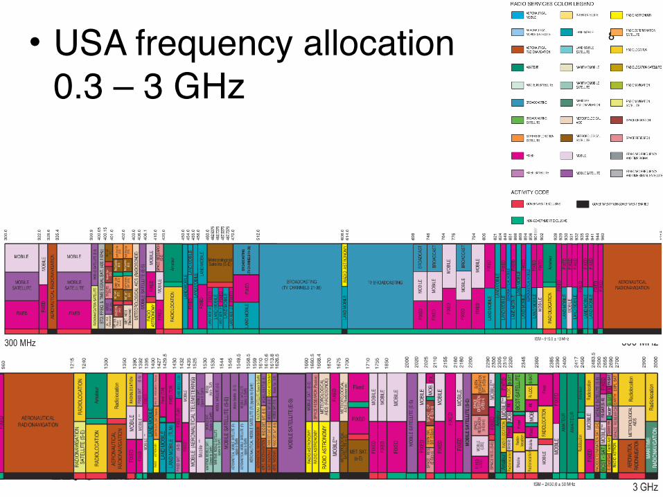
�8• USA frequency allocation 0.3 – 3 GHz
TSEK02 Radio Electronics 2018/Ted Johansson
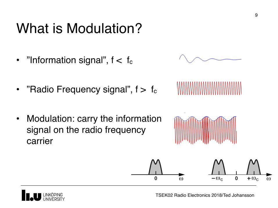
What is Modulation?�9
• ”Information signal”, f < fc
• ”Radio Frequency signal”, f > fc
• Modulation: carry the information signal on the radio frequency carrier

TSEK02 Radio Electronics 2018/Ted Johansson
Modulation�10
• Modulation refers to turning information into (electrical) signals which are suitable for transmission
ModulatorData Information-bearing electrical signal

TSEK02 Radio Electronics 2018/Ted Johansson
Modulation Types
�11
• Signal properties are varied according to the information
• Properties of an RF signal• Amplitude • Frequency • Phase
• This variation could be continuous (analog modulation) or in discrete steps (digital modulation)
TSEK02 Radio Electronics 2018/Ted Johansson
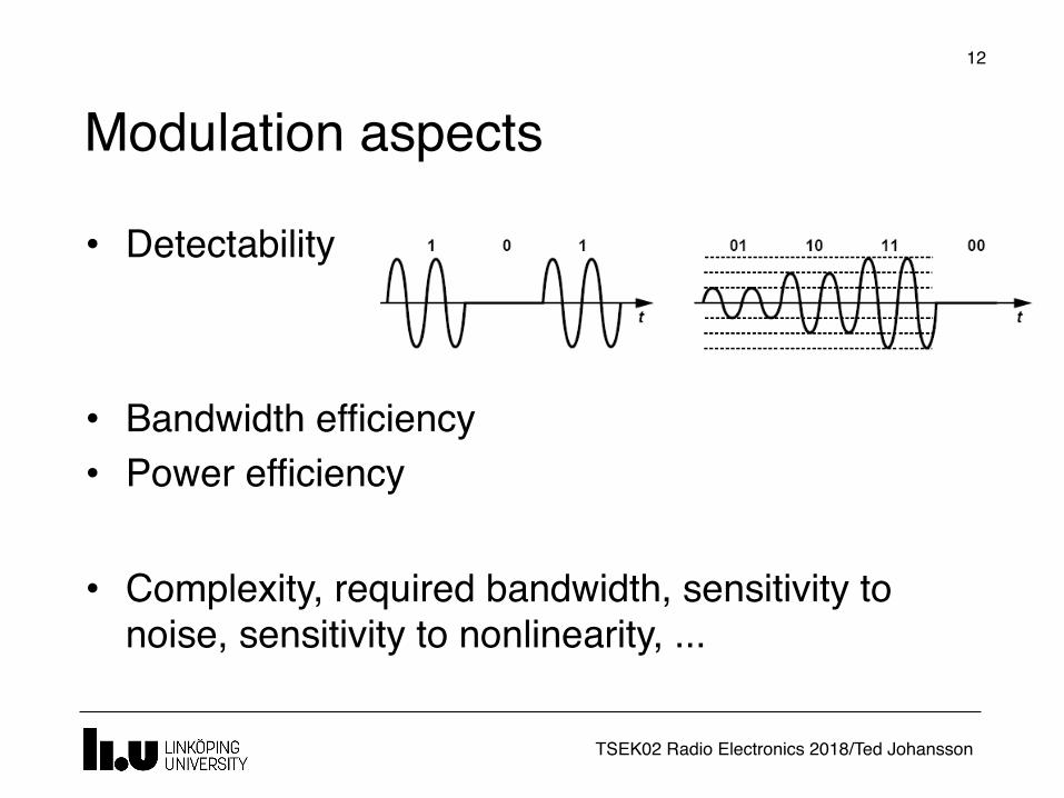
Modulation aspects�12
• Detectability
• Bandwidth efficiency• Power efficiency
• Complexity, required bandwidth, sensitivity to noise, sensitivity to nonlinearity, ...
TSEK02 Radio Electronics 2018/Ted Johansson
An Overview of Modulation Techniques:chapter 3.1 – 3.3.1
�13
• Introduction• Analog Modulation
Amplitude Modulation (3.2.1) Phase and Frequency Modulation
• Digital Modulation• Bandwidth considerations
TSEK02 Radio Electronics 2018/Ted Johansson
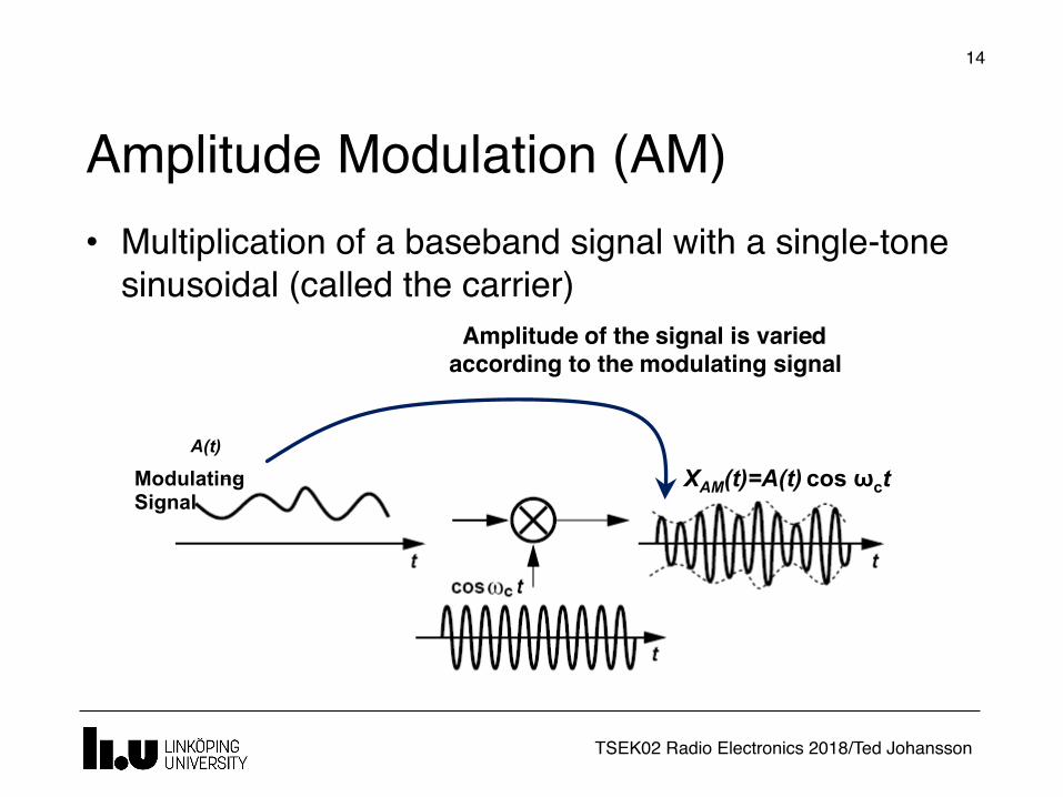
Amplitude Modulation (AM)
�14
• Multiplication of a baseband signal with a single-tone sinusoidal (called the carrier)
Amplitude of the signal is varied according to the modulating signal
Modulating Signal
A(t)
XAM(t)=A(t) cos ωct

TSEK02 Radio Electronics 2018/Ted Johansson
Amplitude Modulation in frequency domain Contains one frequency
Multiplication in the time-domain corresponds to convolution in
frequency-domain
A(f)
Zero will be shifted to the carrier frequency
�15
TSEK02 Radio Electronics 2018/Ted Johansson
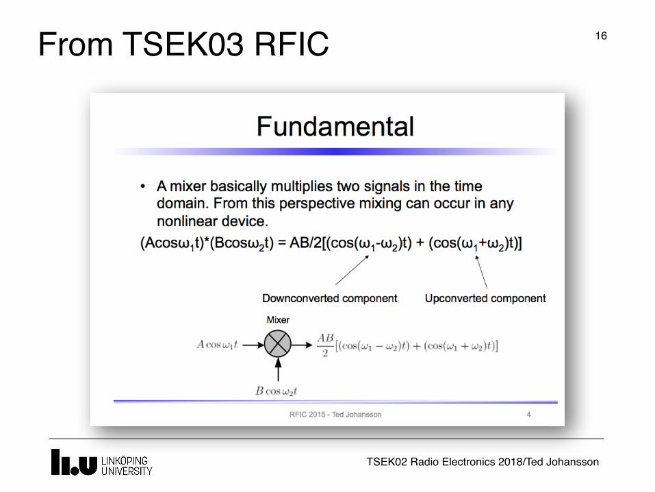
From TSEK03 RFIC �16
TSEK02 Radio Electronics 2018/Ted Johansson
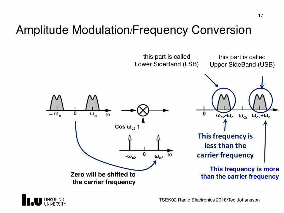
Amplitude Modulation/Frequency Conversion
Zero will be shifted to the carrier frequency
This frequency is more than the carrier frequency
this part is called Upper SideBand (USB)
this part is called Lower SideBand (LSB)
�17

TSEK02 Radio Electronics 2018/Ted Johansson
Amplitude Modulation/Frequency Conversion
A signal with the carrier frequency might also exist at the output.
Possible causes are:1. DC component at the input2. Leakage
�18
TSEK02 Radio Electronics 2018/Ted Johansson
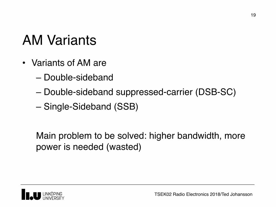
AM Variants
�19
• Variants of AM are– Double-sideband – Double-sideband suppressed-carrier (DSB-SC)– Single-Sideband (SSB)
Main problem to be solved: higher bandwidth, more power is needed (wasted)

TSEK02 Radio Electronics 2018/Ted Johansson
Amplitude Modulation (AM)
�20
• Multiplication of a baseband signal with a single-tone sinusoidal (called the carrier)
Amplitude of the signal is varied according to the modulating signal
Modulating Signal
A(t)
XAM(t)=A(t) cos ωct

TSEK02 Radio Electronics 2018/Ted Johansson
Amplitude Detection (demodulation)
�21
TSEK02 Radio Electronics 2018/Ted Johansson
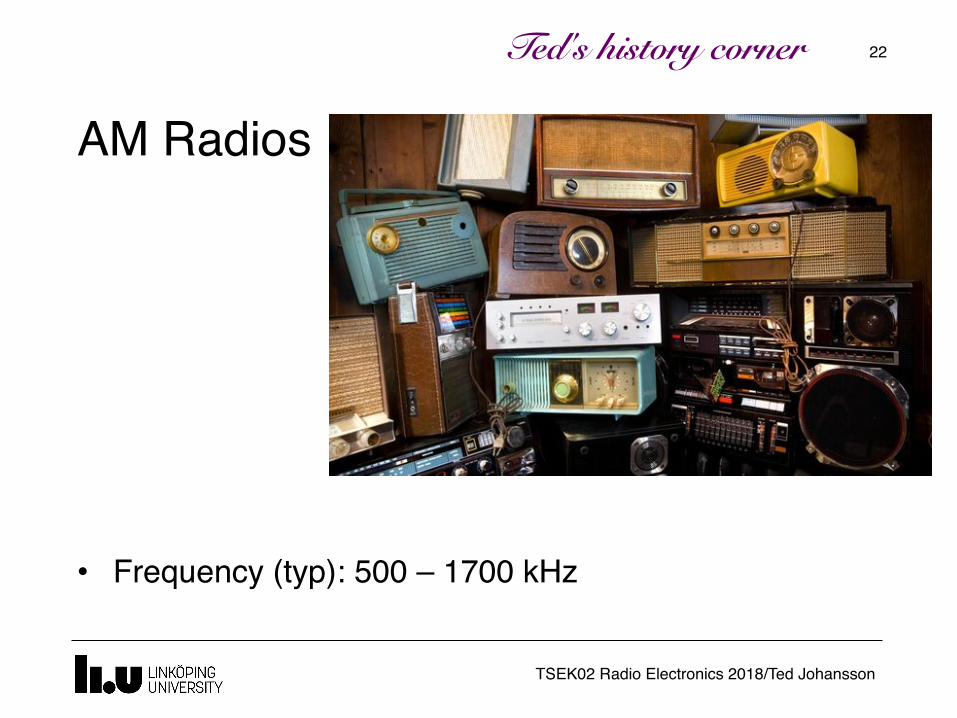
AM Radios
�22
• Frequency (typ): 500 – 1700 kHz
Ted's history corner

TSEK02 Radio Electronics 2018/Ted Johansson
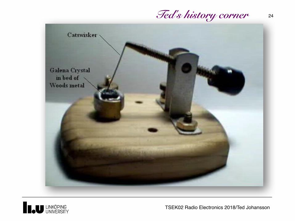
�23Ted's history corner
TSEK02 Radio Electronics 2018/Ted Johansson
�24Ted's history corner
TSEK02 Radio Electronics 2018/Ted Johansson
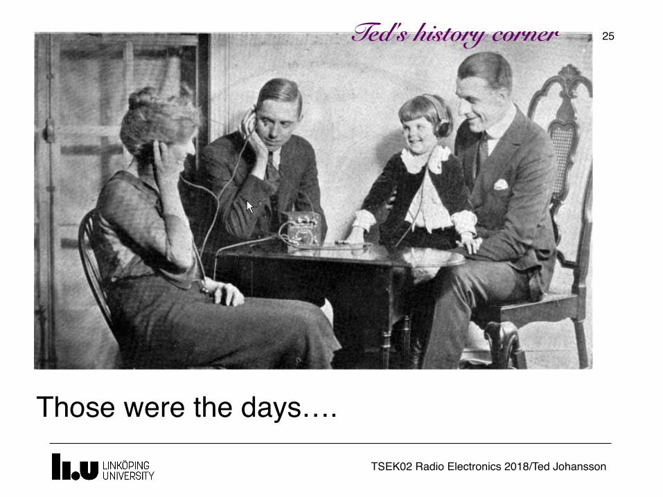
�25
Those were the days….
Ted's history corner
TSEK02 Radio Electronics 2018/Ted Johansson
�26

TSEK02 Radio Electronics 2018/Ted Johansson
An Overview of Modulation Techniques:chapter 3.1 – 3.3.1
�27
• Introduction• Analog Modulation
Amplitude Modulation Phase and Frequency Modulation (3.2.2)
• Digital Modulation• Bandwidth considerations
TSEK02 Radio Electronics 2018/Ted Johansson
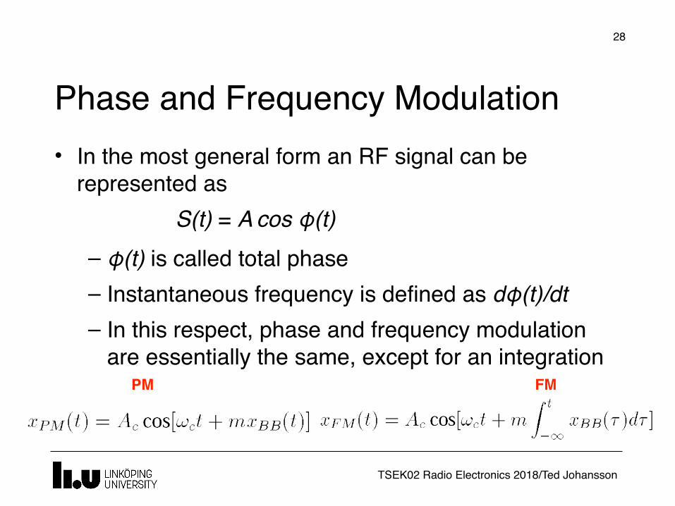
Phase and Frequency Modulation
�28
PM FM
• In the most general form an RF signal can be represented as
S(t) = A cos φ(t)– φ(t) is called total phase– Instantaneous frequency is defined as dφ(t)/dt– In this respect, phase and frequency modulation
are essentially the same, except for an integration
TSEK02 Radio Electronics 2018/Ted Johansson
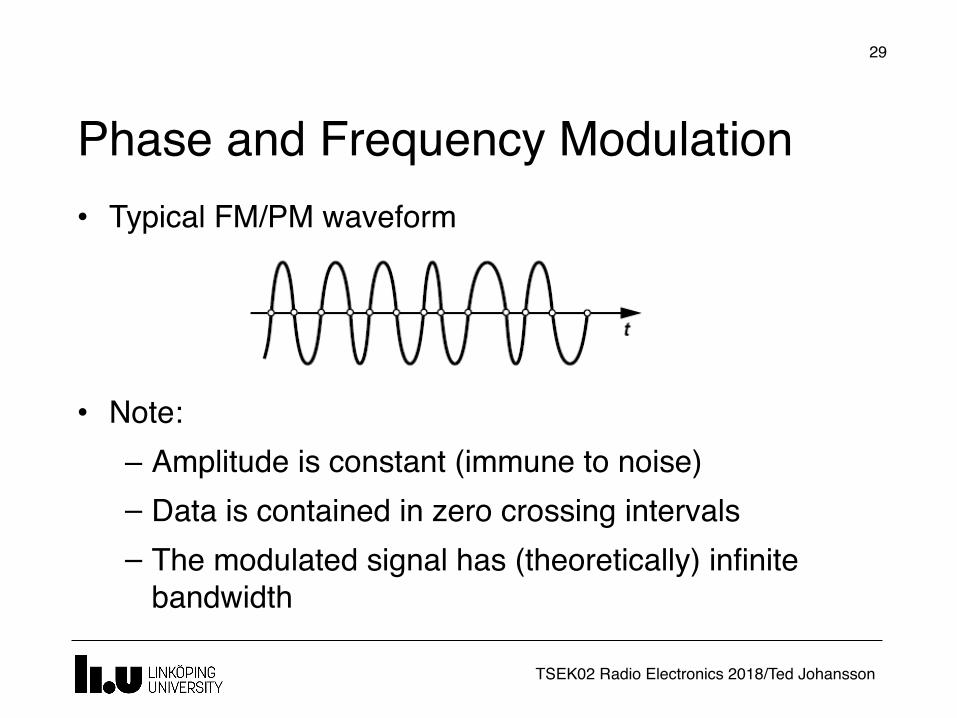
Phase and Frequency Modulation
�29
• Typical FM/PM waveform
• Note:– Amplitude is constant (immune to noise)– Data is contained in zero crossing intervals – The modulated signal has (theoretically) infinite
bandwidth
TSEK02 Radio Electronics 2018/Ted Johansson
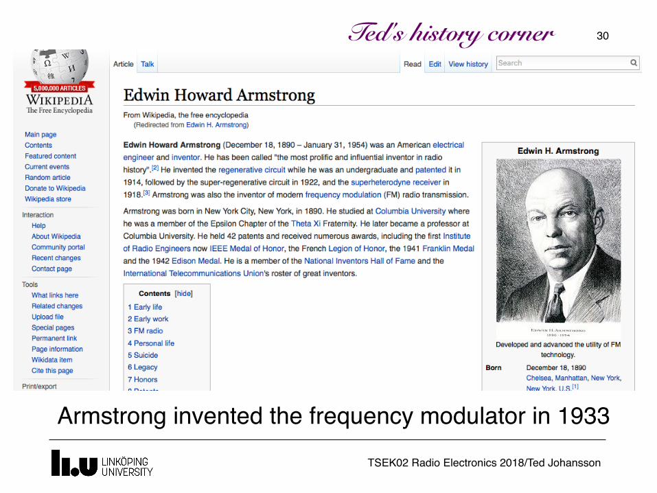
�30Ted's history corner
Armstrong invented the frequency modulator in 1933
TSEK02 Radio Electronics 2018/Ted Johansson
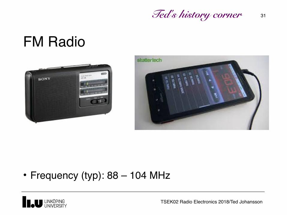
FM Radio
�31
• Frequency (typ): 88 – 104 MHz
Ted's history corner
TSEK02 Radio Electronics 2018/Ted Johansson
An Overview of Modulation Techniques:chapter 3.1 – 3.3.1
�32
• Introduction• Analog Modulation
Amplitude Modulation Phase and Frequency Modulation
• Digital Modulation (3.2)• Bandwidth considerations
TSEK02 Radio Electronics 2018/Ted Johansson
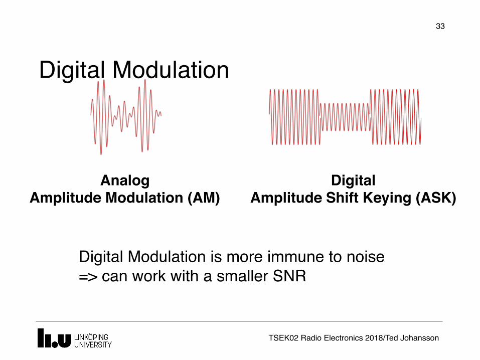
Digital Modulation
Analog Amplitude Modulation (AM)
DigitalAmplitude Shift Keying (ASK)
Digital Modulation is more immune to noise=> can work with a smaller SNR
�33
TSEK02 Radio Electronics 2018/Ted Johansson
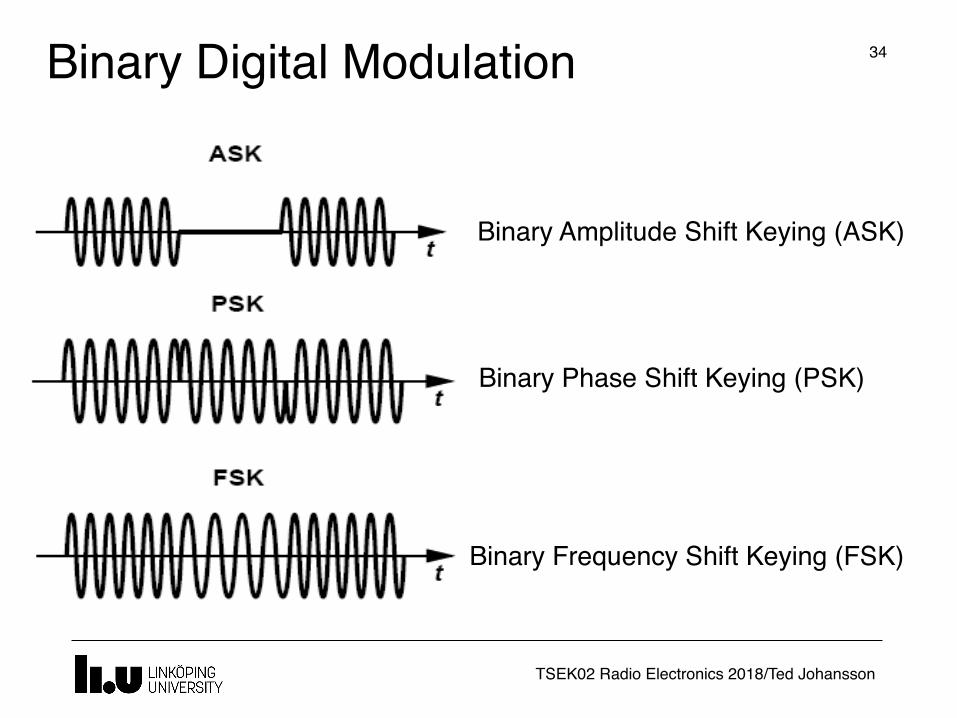
Binary Digital Modulation �34
Binary Phase Shift Keying (PSK)
Binary Amplitude Shift Keying (ASK)
Binary Frequency Shift Keying (FSK)
TSEK02 Radio Electronics 2018/Ted Johansson
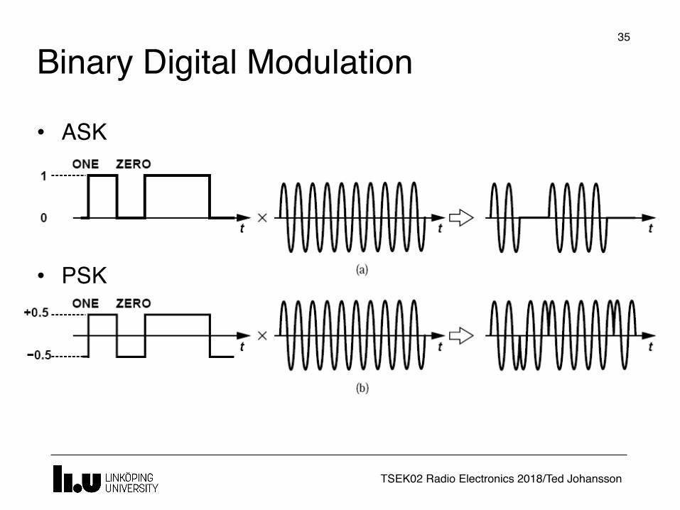
Binary Digital Modulation�35
• ASK
• PSK
TSEK02 Radio Electronics 2018/Ted Johansson
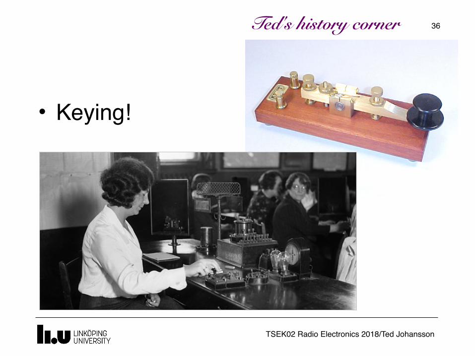
�36Ted's history corner
• Keying!
TSEK02 Radio Electronics 2018/Ted Johansson
An Overview of Modulation Techniques:chapter 3.1 – 3.3.1
�37
• Introduction• Analog Modulation
Amplitude Modulation Phase and Frequency Modulation
• Digital Modulation• Bandwidth considerations (3.3.1)

TSEK02 Radio Electronics 2018/Ted Johansson
Bandwidth�38
• Linear time-invariant systems can "distort" a signal if they do not provide sufficient bandwidth
Each pulse extends in time and spills to the time slot of other pulses. This is called Inter Symbol Interference (ISI).
TSEK02 Radio Electronics 2018/Ted Johansson
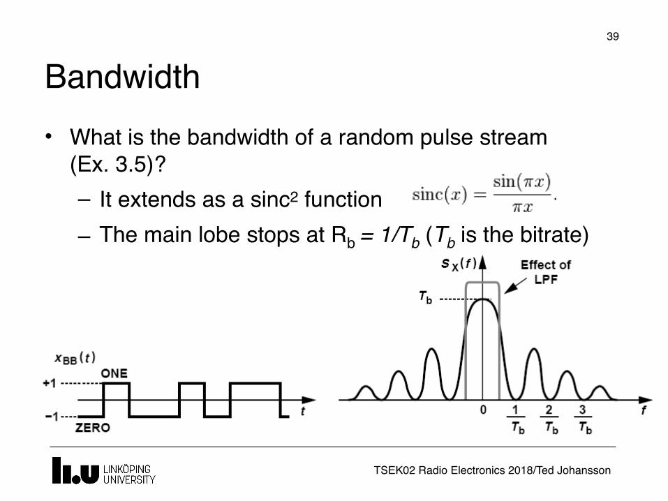
Bandwidth�39
• What is the bandwidth of a random pulse stream (Ex. 3.5)?– It extends as a sinc2 function– The main lobe stops at Rb = 1/Tb (Tb is the bitrate)
TSEK02 Radio Electronics 2018/Ted Johansson
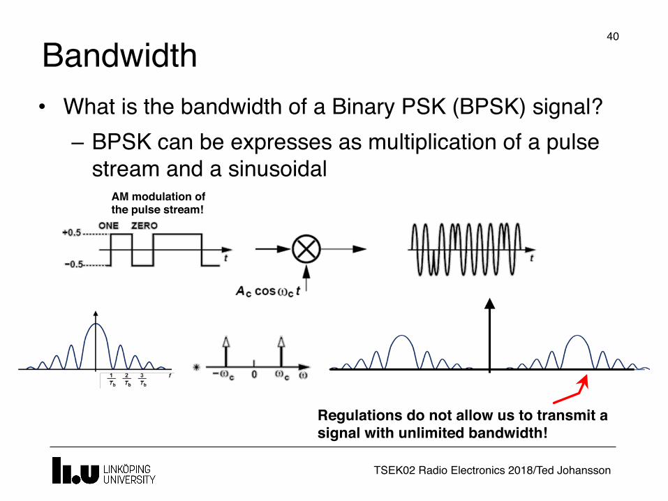
Bandwidth�40
• What is the bandwidth of a Binary PSK (BPSK) signal?– BPSK can be expresses as multiplication of a pulse
stream and a sinusoidalAM modulation of the pulse stream!
Regulations do not allow us to transmit a signal with unlimited bandwidth!
TSEK02 Radio Electronics 2018/Ted Johansson
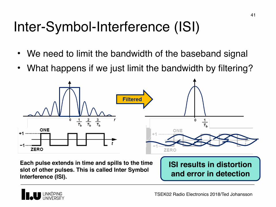
Inter-Symbol-Interference (ISI)�41
• We need to limit the bandwidth of the baseband signal• What happens if we just limit the bandwidth by filtering?
Each pulse extends in time and spills to the time slot of other pulses. This is called Inter Symbol Interference (ISI).
ISI results in distortion and error in detection
TSEK02 Radio Electronics 2018/Ted Johansson
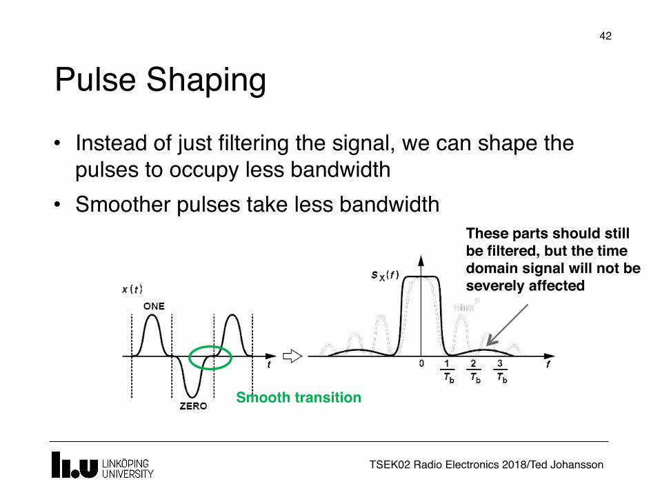
Pulse Shaping�42
• Instead of just filtering the signal, we can shape the pulses to occupy less bandwidth
• Smoother pulses take less bandwidth
Smooth transition
These parts should still be filtered, but the time domain signal will not be severely affected
TSEK02 Radio Electronics 2018/Ted Johansson
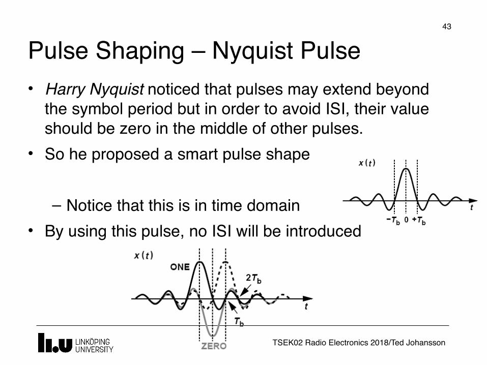
Pulse Shaping – Nyquist Pulse�43
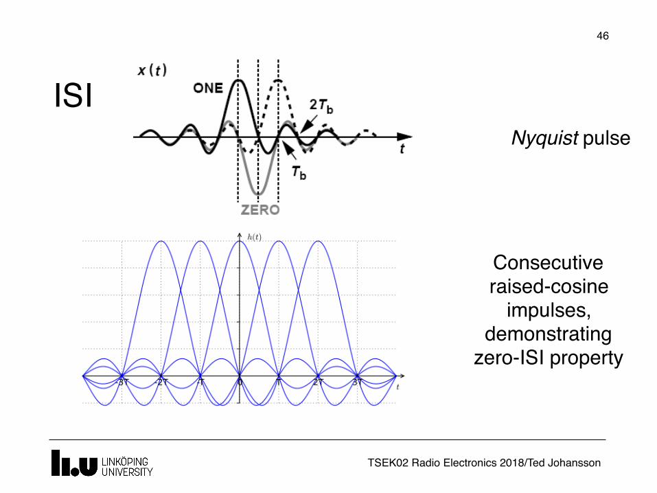
• Harry Nyquist noticed that pulses may extend beyond the symbol period but in order to avoid ISI, their value should be zero in the middle of other pulses.
• So he proposed a smart pulse shape
– Notice that this is in time domain• By using this pulse, no ISI will be introduced

TSEK02 Radio Electronics 2018/Ted Johansson
Optimum Bandwidth
�44
• Nyquist pulse not only removes ISI but also results in the minimum bandwidth for the modulated signal
• With Nyquist pulse, the modulated RF signal occupies Rb=1/Tb Hz The absolute theoretical minimum bandwidth
required to transmit Rb pulses per second!
TSEK02 Radio Electronics 2018/Ted Johansson
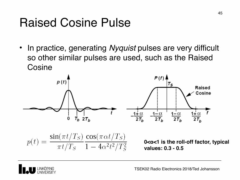
Raised Cosine Pulse�45
• In practice, generating Nyquist pulses are very difficult so other similar pulses are used, such as the Raised Cosine
0<α<1 is the roll-off factor, typical values: 0.3 - 0.5
TSEK02 Radio Electronics 2018/Ted Johansson
ISI
�46
Consecutive raised-cosine
impulses, demonstrating
zero-ISI property
Nyquist pulse
TSEK02 Radio Electronics 2018/Ted Johansson
Ted's history corner
�47Ted's history corner

www.liu.se