tsek02: radio electronics lecture 2: modulation (i) · tsek02 radio electronics 2019/ted johansson...
TRANSCRIPT

TSEK02: Radio ElectronicsLecture 2: Modulation (I)
Ted Johansson, EKS, ISY

TSEK02 Radio Electronics 2019/Ted Johansson
Lab Signup (only required for lab 2)2
• Lab 1 (Simulink) will take place 2019-11-26 17-21 in Olympen . All students, no signup required.
• Lab 2: In Lisam, go to Signup on first course page. 4 students each time.

TSEK02 Radio Electronics 2019/Ted Johansson
An Overview of Modulation Techniques:chapter 3.1 – 3.3.1
3
• Introduction• Analog Modulation
Amplitude Modulation Phase and Frequency Modulation
• Digital Modulation• Bandwidth considerations

TSEK02 Radio Electronics 2019/Ted Johansson
An Overview of Modulation Techniques:chapter 3.1 – 3.3.1
4
• Introduction (3.1)• Analog Modulation
Amplitude Modulation Phase and Frequency Modulation
• Digital Modulation• Bandwidth considerations

TSEK02 Radio Electronics 2019/Ted Johansson
Need for Modulation5
• Every channel has a cut-off frequency (fcut-off)– Theoretically, signals with f > fcut-off cannot
propagate through the channel. There may also be a lower frequency limit.
This problem cannot be solved by amplification!
Human voice is limited to 4 kHz < fcut-off

TSEK02 Radio Electronics 2019/Ted Johansson
The electromagnetic spectrum 6

TSEK02 Radio Electronics 2019/Ted Johansson
7USA frequency allocation 0.3 – 3 GHz

TSEK02 Radio Electronics 2019/Ted Johansson
What is Modulation?8
• ”Information signal”, f < fc
• ”Radio Frequency signal”, f > fc
• Modulation: carry the information signal on the radio frequency carrier
TSEK02 Radio Electronics 2019/Ted Johansson
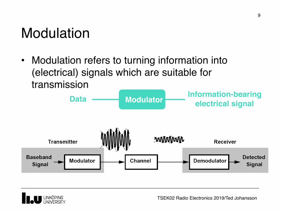
Modulation9
• Modulation refers to turning information into (electrical) signals which are suitable for transmission
ModulatorData Information-bearing electrical signal

TSEK02 Radio Electronics 2019/Ted Johansson
Modulation Types
10
• Signal properties are varied according to the information
• Properties of an RF signal• Amplitude • Frequency • Phase
• This variation could be continuous (analog modulation) or in discrete steps (digital modulation)
TSEK02 Radio Electronics 2019/Ted Johansson
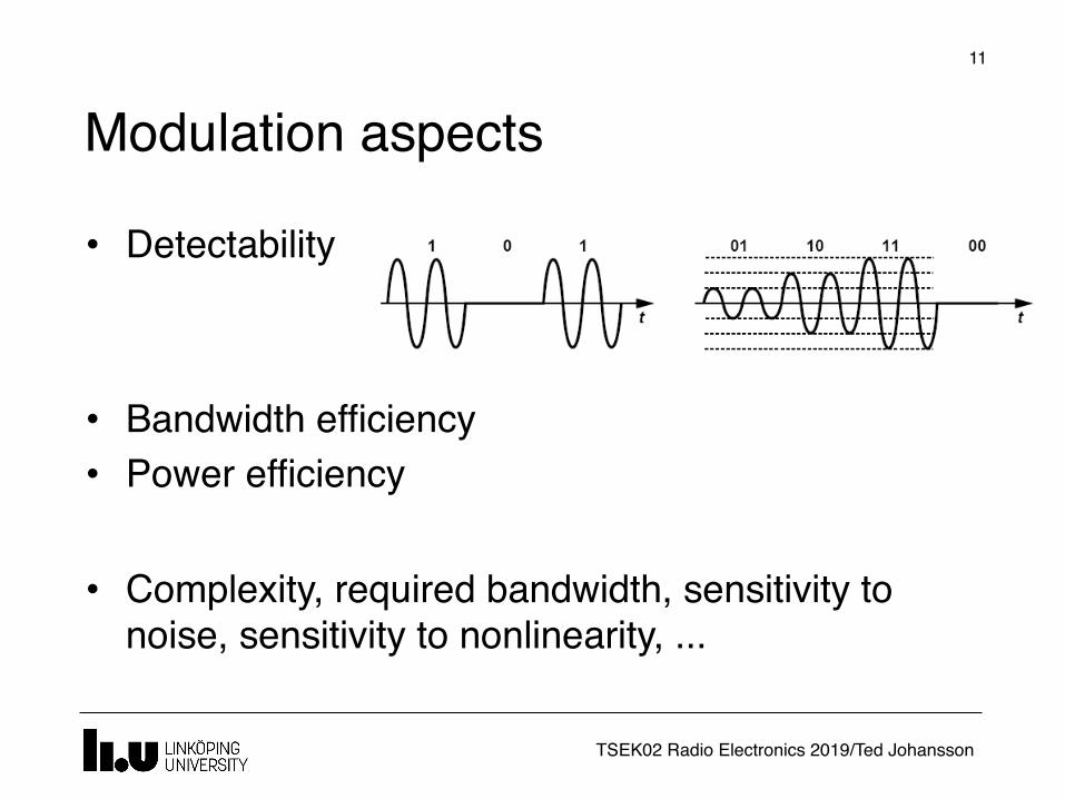
Modulation aspects11
• Detectability
• Bandwidth efficiency• Power efficiency
• Complexity, required bandwidth, sensitivity to noise, sensitivity to nonlinearity, ...

TSEK02 Radio Electronics 2019/Ted Johansson
12Ted's history corner
• Marconi is usually claimed to be the inventor of radio transmissions.
• Tesla (otherwise known for AC) also demonstrated early (1893) wireless communication and wireless power transfer.

TSEK02 Radio Electronics 2019/Ted Johansson
13Ted's history corner
• Marconi used a ”spark-gap transmitter”, which is an obsolete type of radio transmitter which generates radio waves by means of an electric spark.
• A fundamental limitation of spark-gap transmitters is that they generate a series of brief transient pulses of radio waves called damped waves; they are unable to produce the continuous waves used to carry audio (sound) in modern AM or FM radio transmission.
• So spark-gap transmitters could not transmit audio, and instead transmitted information by radiotelegraphy.
• The operator switched the transmitter on and off with a telegraph key, creating pulses of radio waves to spell out text messages in Morse code.
[Wikipedia]

TSEK02 Radio Electronics 2019/Ted Johansson
An Overview of Modulation Techniques:chapter 3.1 – 3.3.1
14
• Introduction• Analog Modulation
Amplitude Modulation (3.2.1) Phase and Frequency Modulation
• Digital Modulation• Bandwidth considerations

TSEK02 Radio Electronics 2019/Ted Johansson
Amplitude Modulation (AM)
15
• Multiplication of a baseband signal with a single-tone sinusoidal (called the carrier)
Amplitude of the signal is varied according to the modulating signal
Modulating Signal
A(t)
XAM(t)=A(t) cos ωct

TSEK02 Radio Electronics 2019/Ted Johansson
Amplitude Modulation in frequency domain Contains one frequency
Multiplication in the time-domain corresponds to convolution in
frequency-domain
A(f)
Zero will be shifted to the carrier frequency
16
TSEK02 Radio Electronics 2019/Ted Johansson
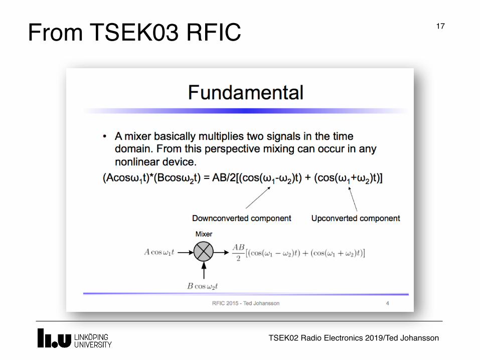
From TSEK03 RFIC 17
TSEK02 Radio Electronics 2019/Ted Johansson
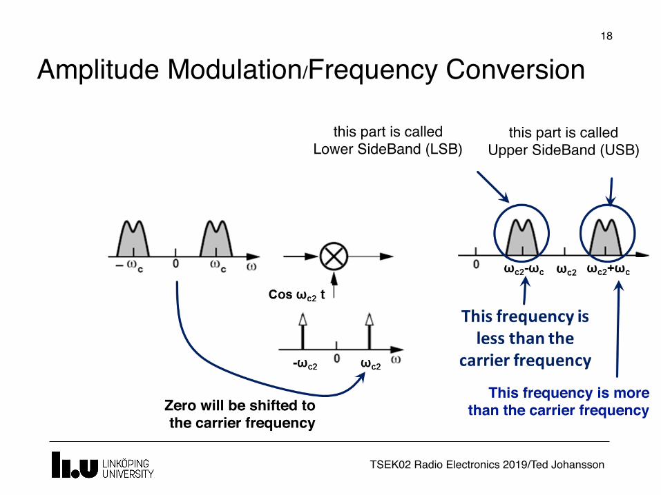
Amplitude Modulation/Frequency Conversion
Zero will be shifted to the carrier frequency
This frequency is more than the carrier frequency
this part is called Upper SideBand (USB)
this part is called Lower SideBand (LSB)
18
TSEK02 Radio Electronics 2019/Ted Johansson
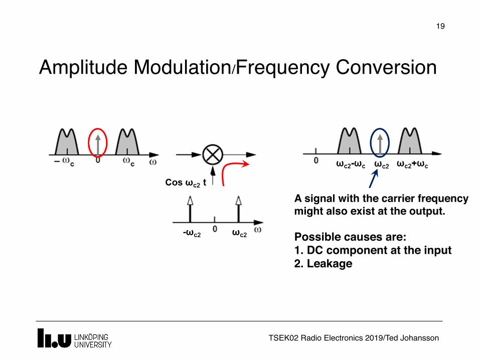
Amplitude Modulation/Frequency Conversion
A signal with the carrier frequency might also exist at the output.
Possible causes are:1. DC component at the input2. Leakage
19

TSEK02 Radio Electronics 2019/Ted Johansson
AM Variants
20
• Variants of AM are– Double-sideband – Double-sideband suppressed-carrier (DSB-SC)– Single-Sideband (SSB)
Main problems to be solved: higher bandwidth, reduce power (wasted in the sidebands or carrier)

TSEK02 Radio Electronics 2019/Ted Johansson
Amplitude Modulation (AM)
21
• Multiplication of a baseband signal with a single-tone sinusoidal (called the carrier)
Amplitude of the signal is varied according to the modulating signal
Modulating Signal
A(t)
XAM(t)=A(t) cos ωct

TSEK02 Radio Electronics 2019/Ted Johansson
Amplitude Detection (demodulation)
22

TSEK02 Radio Electronics 2019/Ted Johansson
AM Radios
23
• Frequency (typ): 500 – 1700 kHz
Ted's history corner
TSEK02 Radio Electronics 2019/Ted Johansson
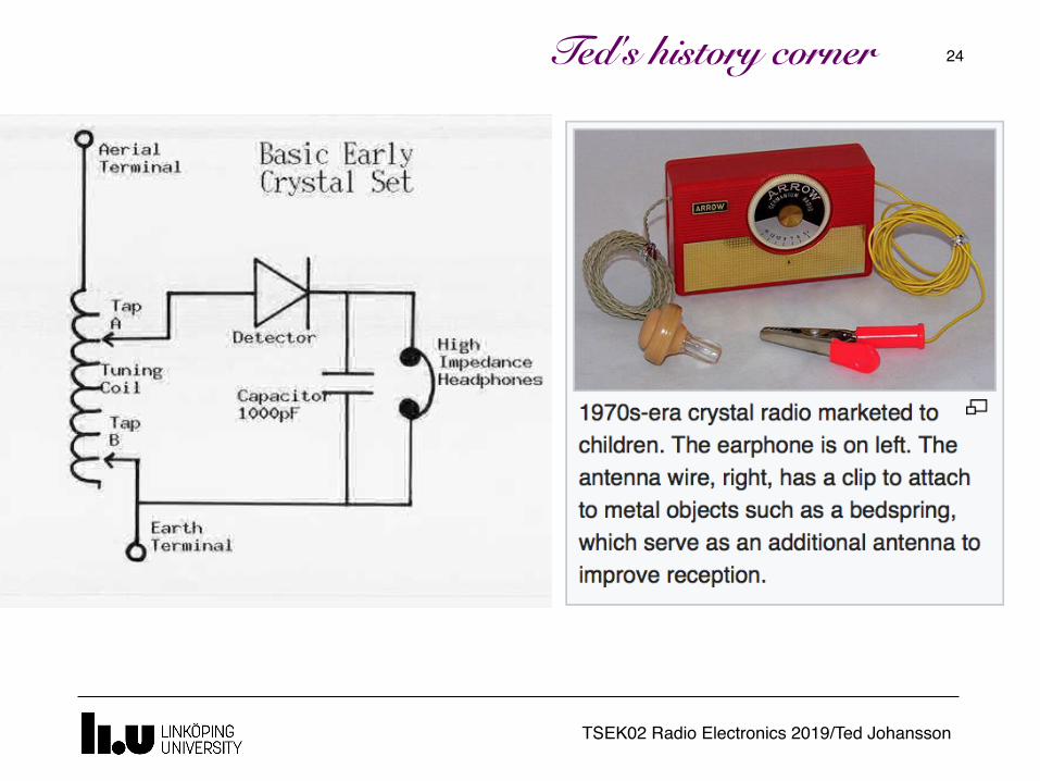
24Ted's history corner

TSEK02 Radio Electronics 2019/Ted Johansson
25Ted's history corner

TSEK02 Radio Electronics 2019/Ted Johansson
26
Those were the days….
Ted's history corner

TSEK02 Radio Electronics 2019/Ted Johansson
27

TSEK02 Radio Electronics 2019/Ted Johansson
An Overview of Modulation Techniques:chapter 3.1 – 3.3.1
28
• Introduction• Analog Modulation
Amplitude Modulation Phase and Frequency Modulation (3.2.2)
• Digital Modulation• Bandwidth considerations

TSEK02 Radio Electronics 2019/Ted Johansson
Phase and Frequency Modulation
29
PM FM
• In the most general form an RF signal can be represented as
S(t) = A cos φ(t)– φ(t) is called total phase– Instantaneous frequency is defined as dφ(t)/dt– In this respect, phase and frequency modulation
are essentially the same, except for an integration

TSEK02 Radio Electronics 2019/Ted Johansson
Phase and Frequency Modulation
30
• Typical FM/PM waveform
• Note:– Amplitude is constant (immune to noise)– Data is contained in zero crossing intervals – The modulated signal has (theoretically) infinite
bandwidth

TSEK02 Radio Electronics 2019/Ted Johansson
31Ted's history corner
Armstrong invented the frequency modulator in 1933

TSEK02 Radio Electronics 2019/Ted Johansson
FM Radio
32
• Frequency (typ): 88 – 104 MHz
Ted's history corner
TSEK02 Radio Electronics 2019/Ted Johansson
An Overview of Modulation Techniques:chapter 3.1 – 3.3.1
33
• Introduction• Analog Modulation
Amplitude Modulation Phase and Frequency Modulation
• Digital Modulation (3.2)• Bandwidth considerations

TSEK02 Radio Electronics 2019/Ted Johansson
Digital Modulation
Analog Amplitude Modulation (AM)
DigitalAmplitude Shift Keying (ASK)
Digital Modulation is more immune to noise=> can work with a smaller Signal-to-Noise Ratio (SNR)
34

TSEK02 Radio Electronics 2019/Ted Johansson
Binary Digital Modulation 35
Binary Phase Shift Keying (PSK)
Binary Amplitude Shift Keying (ASK)
Binary Frequency Shift Keying (FSK)
TSEK02 Radio Electronics 2019/Ted Johansson
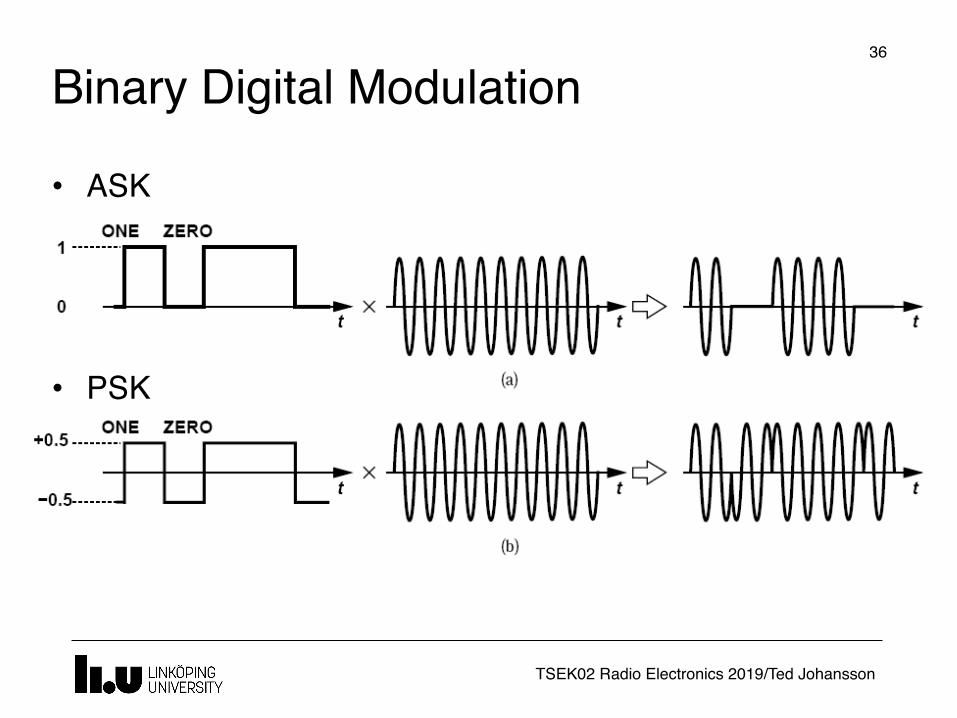
Binary Digital Modulation36
• ASK
• PSK

TSEK02 Radio Electronics 2019/Ted Johansson
37Ted's history corner
• Keying!

TSEK02 Radio Electronics 2019/Ted Johansson
An Overview of Modulation Techniques:chapter 3.1 – 3.3.1
38
• Introduction• Analog Modulation
Amplitude Modulation Phase and Frequency Modulation
• Digital Modulation• Bandwidth considerations (3.3.1)

TSEK02 Radio Electronics 2019/Ted Johansson
Bandwidth39
• Linear time-invariant systems can "distort" a signal if they do not provide sufficient bandwidth
Each pulse extends in time and spills to the time slot of other pulses. This is called Inter Symbol Interference (ISI).

TSEK02 Radio Electronics 2019/Ted Johansson
Bandwidth40
• What is the bandwidth of a random pulse stream (Ex. 3.5)?– It extends as a sinc2 function– The main lobe stops at Rb = 1/Tb (Tb is the bitrate)
TSEK02 Radio Electronics 2019/Ted Johansson
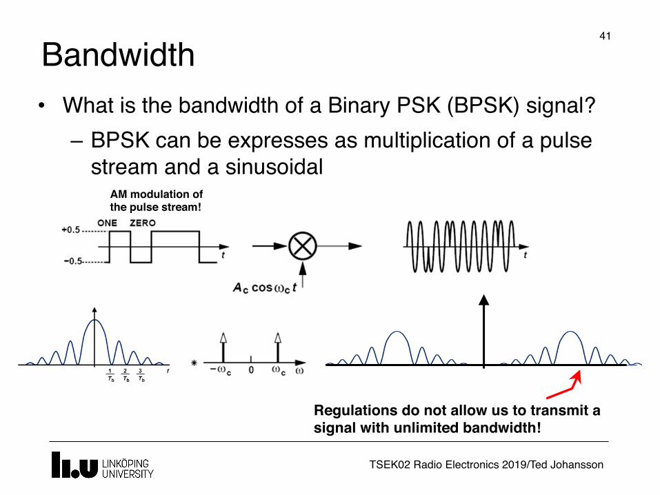
Bandwidth41
• What is the bandwidth of a Binary PSK (BPSK) signal?– BPSK can be expresses as multiplication of a pulse
stream and a sinusoidalAM modulation of the pulse stream!
Regulations do not allow us to transmit a signal with unlimited bandwidth!

TSEK02 Radio Electronics 2019/Ted Johansson
Inter-Symbol-Interference (ISI)42
• We need to limit the bandwidth of the baseband signal• What happens if we just limit the bandwidth by filtering?
Each pulse extends in time and spills to the time slot of other pulses. This is called Inter Symbol Interference (ISI).
ISI results in distortion and error in detection

TSEK02 Radio Electronics 2019/Ted Johansson
Pulse Shaping43
• Instead of just filtering the signal, we can shape the pulses to occupy less bandwidth
• Smoother pulses take less bandwidth
Smooth transition
These parts should still be filtered, but the time domain signal will not be severely affected

TSEK02 Radio Electronics 2019/Ted Johansson
Pulse Shaping – Nyquist Pulse44
• Harry Nyquist noticed that pulses may extend beyond the symbol period but in order to avoid ISI, their value should be zero in the middle of other pulses.
• So he proposed a smart pulse shape:
– Notice that this is in time domain• By using this pulse, no ISI will be introduced
TSEK02 Radio Electronics 2019/Ted Johansson
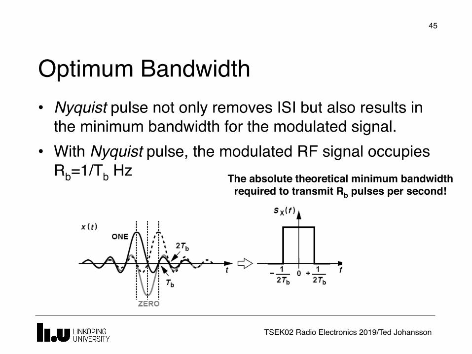
Optimum Bandwidth
45
• Nyquist pulse not only removes ISI but also results in the minimum bandwidth for the modulated signal.
• With Nyquist pulse, the modulated RF signal occupies Rb=1/Tb Hz The absolute theoretical minimum bandwidth
required to transmit Rb pulses per second!

TSEK02 Radio Electronics 2019/Ted Johansson
Raised Cosine Pulse46
• In practice, generating Nyquist pulses are very difficult so other similar pulses are used, such as the Raised Cosine
0<α<1 is the roll-off factor, typical values: 0.3 - 0.5
TSEK02 Radio Electronics 2019/Ted Johansson
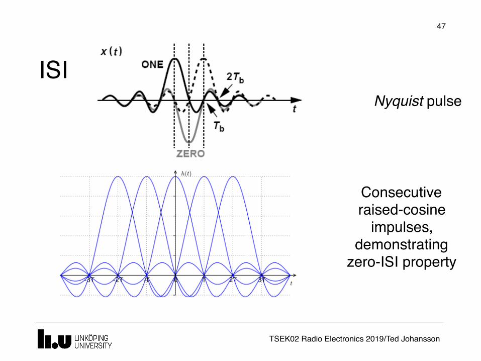
ISI
47
Consecutive raised-cosine
impulses, demonstrating
zero-ISI property
Nyquist pulse

TSEK02 Radio Electronics 2019/Ted Johansson
Ted's history corner
48Ted's history corner

www.liu.se