tufnell road yeronga sps sp069 backup generator om manual
TRANSCRIPT
0o tR
Tufnell Road Yeronga SPS SP069 Backup Generator OM Manual
Q-Pulse Id TMS709 Active 29/01/2014 Page 1 of 346

0
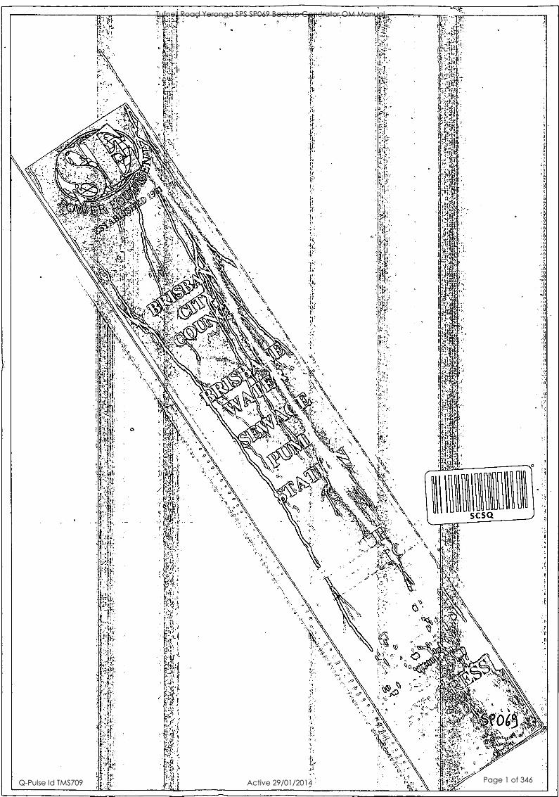
4)? EQUV ESTABLISHED 1981
OPERATION and MAINTENANCE MANUALS
For
BRISBANE CITY COUNCIL
At
BRISBANE WATER
SEWAGE PUMP STATION
SP069 PROGRESS ROAD
Manuals Prepared by:
S E Power Equipment 47 Proprietary Street Tingalpa, Old 4173
Phone No. 07 3890 1744
Copyright © 2002 All Rights Reserved
REVISION B: July 2003
Tufnell Road Yeronga SPS SP069 Backup Generator OM Manual
Q-Pulse Id TMS709 Active 29/01/2014 Page 2 of 346

OPERATION and MAINTENANCE MANUALS
Revision Status
Revision Date Initials Comments
A 26/05/03 JP Issued for approval
B 30/07/03 JP
Prepared by: Jim Pringle Date:
Reviewed Project Manager: Date:
14291_Brisbane_Water_O&M_SP069_Manual.doc
Tufnell Road Yeronga SPS SP069 Backup Generator OM Manual
Q-Pulse Id TMS709 Active 29/01/2014 Page 3 of 346

OPERATION and MAINTENANCE MANUALS
TABLE OF CONTENTS
Section 1. Instructions for use
Section 2. John Deere Operation Manual
Section 3. John Deere Spare Parts Catalogue
Section 4. Stamford Installation, Service & Maintenance Manual
Section 5. PLC - GE Fanuc
Section 6. Functional Description
Section 7. Drawings
Section 8. Test Reports
14291_Brisbane_Water_O&M_SP069_Manual.doc
Tufnell Road Yeronga SPS SP069 Backup Generator OM Manual
Q-Pulse Id TMS709 Active 29/01/2014 Page 4 of 346

OPERATION and MAINTENANCE MANUALS CSIVISJ311(11
INSTRUCTIONS FOR USE
1. Units placed on site using "Hook Truck" (Cleanaway Type) over cable pit.
2. Cable pit to be under switchboard section of unit (rear).
3. Attach hold down / anti-theft chains to location points at rear of unit (beside switchboard).
4. Check engine lube oil level.
5. Check engine coolant level.
6. Check the battery is connected and the electrolyte level is correct.
7. Connect cables to plugs via colour-coded sequence.
8. Connect power inlet socket (240V).
9. Connect communication socket.
10. Connect pump station control socket.
11. Check fuel level (mechanical gauge beside fill point).
12. Refer to section 6, Functional Description for start/run and connection procedure.
13. Remember SAFETY is important ALWAYS wear your Personal Protection Equipment (PPE)
14291_Brisbane_Water_O&M_SP069_Manual.doc
Tufnell Road Yeronga SPS SP069 Backup Generator OM Manual
Q-Pulse Id TMS709 Active 29/01/2014 Page 5 of 346

POWER Units for Gensets (Saran)
2.9L/4039/4.5/6.8L (128/008/158/258)
O -A
John Deere Usine de Saran OMCD16564 (03JAN00)
Printed in Germany ENGLISH
)111111L JOHN DEERE POWER
Tufnell Road Yeronga SPS SP069 Backup Generator OM Manual
Q-Pulse Id TMS709 Active 29/01/2014 Page 6 of 346
Introduction THIS MANUAL COVERS the following engines for generator sets:
ENGINE FAMILY 300-SERIES
POWERTECH®
ENGINE MODEL CD3029DF128 CD4039DF008 CD4039TF008 CD4045DF158 CD4045HF158 CD4045TF158 CD4045TF258 CD6068HF158 CD6068TF158 CD6068TF258
READ THIS MANUAL carefully to learn how to operate and service your engine correctly. Failure to do so could result in personal injury or equipment damage.
THIS MANUAL SHOULD BE CONSIDERED a permanent part of your engine and should remain with the engine when you sell it.
MEASUREMENTS IN THIS MANUAL are given in metric. Use only correct replacement parts and fasteners. Metric and inch fasteners may require a specific metric or inch wrench.
WRITE ENGINE SERIAL NUMBERS and option codes in the spaces indicated in the Record Keeping Section. Accurately record all the numbers. Your dealer also needs these numbers when you order parts. File the identification numbers in a secure place off the engine or machine.
RIGHT-HAND AND LEFT-HAND sides are determined by standing at the drive or flywheel end (rear) of the engine and facing toward the front of the engine.
SETTING FUEL DELIVERY beyond published factory specifications or otherwise overpowering will result in loss of warranty protection for this engine.
POWERTECH is a trademark of Deere & Company
Information relative to emissions regulations Depending on final destination, this engine can meet the emissions regulations according to the US Environmental Protection Agency (EPA), California Air Resources Board (CARB) and for Europe, the Directive 97/68/EC relating the measures against the emissions of gaseous and particulates pollutants from internal combustion engines. In this case an emission label is stuck on the engine.
Emission regulations prohibit tampering with the emission-related components listed below which would render that component inoperative or to make any adjustment on the engine beyond published specifications. It is also illegal to install a part or component where the principal effect of that component is to bypass, defeat, or render inoperative any engine component or device which would affect the engine conformance to the emissions regulations. To summarize, it is illegal to do anything except return the engine to its original published specifications.
List of emission-related components:
Fuel injection pump Intake manifold Turbocharger Charge air cooling system Piston
CALIFORNIA PROPOSITION 65 WARNING Diesel engine exhaust and some of its constituents are known to
the State of California to cause cancer, birth defects and other reproductive harm.
DPSG,CD03523,1 -19-01JUL99-1/1
112699
PN =2
Tufnell Road Yeronga SPS SP069 Backup Generator OM Manual
Q-Pulse Id TMS709 Active 29/01/2014 Page 7 of 346

Contents Page
Identification Views Identification views 01-1
Maintenance Records Using maintenance records 02-1
100 Hours of operation 02-1 500 Hours of operation 02-2 1000 Hours of operation 02-2 1500 Hours of operation 02-3 2000 Hours of operation 02-3 2500 Hours of operation 02-4 3000 Hours of operation 02-4 3500 Hours of operation 02-5 4000 Hours of operation 02-5 4500 Hours of operation 02-6
.00 Hours of operation 02-6 500 Hours of operation 02-7
6000 Hours of operation 02-7 6500 Hoirrs of operation 02-8 7000 Hours of operation 02-8 7500 Hours of operation 02-9 8000 Hours of operation 02-9 8500 Hours of operation 02-10 9000 Hours of operation 02-10 9500 Hours of operation 02-11 10000 Hours of operation 02-11
Record Keeping POWERTech® medallion 03-1 Engine serial number plate 03-1 Record engine serial number 03-2 Engine option codes 03-3 Record fuel injection pump model number 03-5
dafety 05-1
Fuels, Lubricants and Coolant Diesel Fuel 10-1
Handling and Storing Diesel Fuel 10-1 Engine Break-In Oil 10-2 Diesel Engine Oil 10-3 Lubricant Storage 10-3 Mixing of Lubricants 10-4
Page
Diesel Engine Coolant 10-4 Operating in Warm Temperature Climates 10-5
Operating the Engine Break-in period 15-1
Starting the engine 15-1 Cold weather operation 15-1 Using a booster battery or charger 15-3 Engine operation 15-4 Standby power units 15-4 Stopping the engine 15-5
Maintenance Observe service intervals 20-1 Use correct fuels, lubricants and coolant 20-1 Maintenance interval chart 20-2
Maintenance/Daily or every 10 hours Daily prestarting checks 25-1
Maintenance/500 hours Changing engine oil and filter 30-1 Replacing fuel filter element 30-3 Checking belt (300-SERIES ENGINES) 30-4 Checking belt (POWERTech ENGINES with
manual tensioner) 30-5
Maintenance/1000 hours/1 year Cleaning crankcase vent tube 35-1 Checking air intake system 35-1 Checking automatic belt tensioner
(POWERTech ENGINES) 35-2 Check and adjust engine valve clearance
(300-SERIES ENGINES) 35-3
Maintenance/2000 hours/2 years Check and adjust engine valve clearance
(POWERTech ENGINE) 40-1 Checking engine speed 40-3 Adjust speed droop governor 40-3
Continued on next page
All information, illustrations and specifications in this manual are based on the latest information available at the time of publication. The right is re- served to make changes at any time without notice.
COPYRIGHT ° 1999 DEERE 8 COMPANY
European Office Mannheim All rights reserved
A John Deere ILLUSTRUCTION* Manual
112699
PN=1
Tufnell Road Yeronga SPS SP069 Backup Generator OM Manual
Q-Pulse Id TMS709 Active 29/01/2014 Page 8 of 346

Contents
Page
Checking crankshaft vibration damper (6-CYLINDER ENGINE ONLY) 40-4
Maintenance/2500 hours/3 years Drain and flush cooling system 45-1
Maintenance/As required Additional service information 50-1 Do not modify fuel system 50-1 Clean or replace air filter (one-piece) 50-2 Clean or replace air filter element 50-3 Replacing fan and alternator belt
(POWERTech ENGINES) 50-4 Checking fuel filter 50-5 Bleeding the fuel system 50-6
Troubleshooting Engine troubleshooting 55-1 Electrical troubleshooting 55-6
Storage Engine storage guidelines 60-1 Use AR41785 engine storage kit 60-1 Preparing engine for long term storage 60-2 Removing engine from long term storage 60-3
Specifications General engine specifications 65-1 Unified Inch Bolt and Cap Screw Torque
Values 65-4 Metric Bolt and Cap Screw Torque Values 65-5
i i 112699
PN=2
Tufnell Road Yeronga SPS SP069 Backup Generator OM Manual
Q-Pulse Id TMS709 Active 29/01/2014 Page 9 of 346

Identification Views IDENTIFICATION VIEWS
1P1
1111611161.1.4 awe
4045HF158
Continued on next page DPSG,CD03523,3 -19- -05JUL99-1/2
01-1 112699
PN=5
Tufnell Road Yeronga SPS SP069 Backup Generator OM Manual
Q-Pulse Id TMS709 Active 29/01/2014 Page 10 of 346

Identification Views
6068HF158
DPSG,CD03523,3 -19-05JUL99-2/2
01 -2 112699
PN=6
Tufnell Road Yeronga SPS SP069 Backup Generator OM Manual
Q-Pulse Id TMS709 Active 29/01/2014 Page 11 of 346

Maintenance Records USING MAINTENANCE RECORDS
To obtain the best performance, economy and service life from your engine, ensure service is carried out according to this present manual and recorded in the following pages. It is recommended that your engine Distributor or your Dealer carry out this service work and stamp the appropriate case.
Keeping an accurate account of all service performed on your engine will give more value to the machine when you resell it.
John Deere oils and coolants have been formulated to give maximum protection and performance to your engine. We recommend only genuine John Deere service products and replacement parts.
To protect your rights under the warranty ensure all scheduled services are carried out and recorded. If
your engine is covered by extended warranty, it is important to maintain this record for the duration of the warranty.
DPSG,CD03523,6 -19-05JUL99-1/1
100 HOURS OF OPERATION
0 Engine oil, replace
0 Engine oil filter, replace
0 Hose connections, check .
Number of hours:
Date:
Job done by:
Comments: Dealer or distributor stamp
DPSG,CD03523,7 -19-05JUL99-1/1
02-1 112699
PN=7
Tufnell Road Yeronga SPS SP069 Backup Generator OM Manual
Q-Pulse Id TMS709 Active 29/01/2014 Page 12 of 346

Maintenance Records
500 HOURS OF OPERATION
O Engine oil, replace 0 Engine oil filter, replace
0 Fuel filter, replace
0 Belt, check tension and wear (300-Series and POWERTech with manual tensioner)
O Valve clearance, adjust (300-Series)
Number of hours:
Date:
Job done by:
Comments: Dealer or distributor stamp
DPSG,CD03523,8 -19-05JUL99-1/1
1000 HOURS OF OPERATION
0 Engine oil, replace
0 Engine oil filter, replace
0 Fuel filter, replace
0 Check belt and tensioning system
0 Crankcase vent tube, clean
(
0 Air intake system, check
Number of hours:
Date:
Job done by:
Comments: Dealer or distributor stamp
DPSG,CD03523,9 -19-05JUL99-1/1
02-2 112699
PN=8
Tufnell Road Yeronga SPS SP069 Backup Generator OM Manual
Q-Pulse Id TMS709 Active 29/01/2014 Page 13 of 346

Maintenance Records
1500 HOURS OF OPERATION
0 Engine oil, replace
0 Engine oil filter, replace
0 Fuel filter, replace
0 Belt, check tension and wear (300-Series and POWERTech with manual tensioner)
0 Valve clearance, adjust (300-Series)
Number of hours:
Date:
Job done by:
Comments:
-
Dealer or distributor stamp
DPSG,CD03523,10 -19-05JUL99-1/1
2000 HOURS OF OPERATION
0 Engine oil, replace 0 Cooling system, drain and flush (if COOL-GARD is not used)
0 Engine oil filter, replace 0 Valve clearance, adjust (POWERTech)
0 Fuel filter, replace 0 Air intake system, check
0 Check belt and tensioning system 0 Vibration damper, check
Crankcase vent tube, clean
Number of hours:
Date:
Job done by:
Comments: Dealer or distributor stamp
DPSG,CD03523,59 -19-16AUG99-1/1
02-3 112699
PN=9
Tufnell Road Yeronga SPS SP069 Backup Generator OM Manual
Q-Pulse Id TMS709 Active 29/01/2014 Page 14 of 346

Maintenance Records
2500 HOURS OF OPERATION
0 Engine oil, replace 0 Cooling system, drain and flush (if COOL-GARD is used)
O Engine oil filter, replace
O Fuel filter, replace
O Belt, check tension and wear (300-Series and POWERTech with manual tensioner)
O Valve clearance, adjust (300-Series)
Number of hours:
Date:
Job done by:
Comments: Dealer or distributor stamp
DPSG,C D03523,60 -19-16AUG99-1/1
3000 HOURS OF OPERATION
0 Engine oil, replace
0 Engine oil filter, replace
O Fuel filter, replace
O Check belt and tensioning system
O Crankcase vent tube, clean
0 Air intake system, check
Number of hours:
Date:
Job done by:
Comments: Dealer or distributor stamp
DPSG,C D03523,61 -19-16AUG99-1/1
02-4 112699
PN=10
Tufnell Road Yeronga SPS SP069 Backup Generator OM Manual
Q-Pulse Id TMS709 Active 29/01/2014 Page 15 of 346

Maintenance Records
3500 HOURS OF OPERATION
O Engine oil, replace
O Engine oil fitter, replace
0 Fuel filter, replace
O Belt, check tension and wear (300-Series and POWERTech with manual tensioner)
0 Valve clearance, adjust (300-Series)
Number of hours:
Date:
Ilb done by:
Comments:
- _
Dealer or distributor stamp
DPSG,CD03523,62 -19-16AUG99-1/1
4000 HOURS OF OPERATION
0 Engine oil, replace 0 Cooling system, drain and flush (if COOL-GARD is not used)
0 Engine oil filter, replace 0 Valve clearance, adjust (POWERTech)
0 Fuel filter, replace 0 Air intake system, check
O Check belt and tensioning system 0 Vibration damper, check
Crankcase vent tube, clean
Number of hours:
Date:
Job done by:
Comments: Dealer or distributor stamp
DPSG,CD03523,63 -19-16AUG99-1/1
02-5 112699
PN=11
Tufnell Road Yeronga SPS SP069 Backup Generator OM Manual
Q-Pulse Id TMS709 Active 29/01/2014 Page 16 of 346

Maintenance Records
4500 HOURS OF OPERATION
0 Engine oil, replace 0 Vibration damper, replace (6 cyl.)
0 Engine oil filter, replace
O Fuel filter, replace
0 Belt, check tension and wear (300-Series and POWERTech with manual tensioner)
0 Valve clearance, adjust (300-Series)
Number of hours:
Date:
Job done by:
Comments: Dealer or distributor stamp
DPSG,CD03523,64 -19-16AUG99-1/1
5000 HOURS OF OPERATION
O Engine oil, replace 0 Injection nozzles, replace
0 Engine oil filter, replace 0 Air intake system, check
O Fuel filter, replace 0 Cooling system, drain and flush (if COOL-GARD is used)
0 Check belt and tensioning system
0 Crankcase vent tube, clean
Number of hours:
Date:
Job done by:
Comments: Dealer or distributor stamp
DPSG,CD03523,65 -19-16AUG99-1/1
02-6 112699
PN=12
Tufnell Road Yeronga SPS SP069 Backup Generator OM Manual
Q-Pulse Id TMS709 Active 29/01/2014 Page 17 of 346
Maintenance Records
5500 HOURS OF OPERATION
CI Engine oil, replace
0 Engine oil filter, replace
0 Fuel filter, replace
O Belt, check tension and wear (300-Series and POWERTech with manual tensioner)
O Valve clearance, adjust (300-Series)
Number of hours:
Date:
111,b done by:
Comments: Dealer or distributor stamp
DPSG,CD03523,66 -19-16AUG99-1/1
6000 HOURS OF OPERATION
0 Engine oil, replace 0 Cooling system, drain and flush (if COOL-GARD is not used)
0 Engine oil filter, replace 0 Valve clearance, adjust (POWERTech)
0 Fuel filter, replace . 0 Air intake system, check
0 Check belt and tensioning system 0 Vibration damper, check
1, Crankcase vent tube, clean
Number of hours:
Date:
Job done by:
Comments: Dealer or distributor stamp
DPSG,CD03523,67 -19-16AUG99-1/1
02-7 112699
PN=13
Tufnell Road Yeronga SPS SP069 Backup Generator OM Manual
Q-Pulse Id TMS709 Active 29/01/2014 Page 18 of 346
Maintenance Records
6500 HOURS OF OPERATION
O Engine oil, replace
O Engine oil filter, replace
O Fuel filter, replace
0 Belt, check tension and wear (300-Series and POWERTech with manual tensioner)
0 Valve clearance, adjust (300-Series)
Number of hours:
Date:
Job done by:
Comments: Dealer or distributor stamp
DPSG,C 003523,68 -19-16AUG99-1/1
7000 HOURS OF OPERATION
0 Engine oil, replace
0 Engine oil filter, replace
0 Fuel filter, replace
0 Check belt and tensioning system
0 Crankcase vent tube, clean
0 Air intake system, check
Number of hours:
Date:
Job done by:
Comments: Dealer or distributor stamp
DPSG,C D03523,69 -19-16AUG99-1/1
02-8 112699
PN=14
Tufnell Road Yeronga SPS SP069 Backup Generator OM Manual
Q-Pulse Id TMS709 Active 29/01/2014 Page 19 of 346

Maintenance Records
7500 HOURS OF OPERATION
O Engine oil, replace 0 Cooling system, drain and flush (if COOL-GARD is used)
O Engine oil filter, replace
0 Fuel filter, replace
0 Belt, check tension and wear (300-Series and POWERTech with manual tensioner)
0 Valve clearance, adjust (300-Series)
Number of hours:
Date:
111, done by:
Comments: Dealer or distributor stamp
DPSG,CD03523,70 -19-16AUG99-1/1
8000 HOURS OF OPERATION
0 Engine oil, replace 0 Cooling system, drain and flush (if COOL-GARD is not used)
0 Engine oil filter, replace 0 Valve clearance, adjust (POWERTech)
0 Fuel filter, replace 0 Air intake system, check
0 Check belt and tensioning system 0 Vibration damper, check
110 Crankcase vent tube, clean
Number of hours:
Date:
Job done by:
Comments: Dealer or distributor stamp
DPSG,CD03523,71 -19-16AUG99-1/1
02-9 112699
PN=15
Tufnell Road Yeronga SPS SP069 Backup Generator OM Manual
Q-Pulse Id TMS709 Active 29/01/2014 Page 20 of 346

Maintenance Records
8500 HOURS OF OPERATION
CI Engine oil, replace
CI Engine oil filter, replace
El Fuel filter, replace
El Belt, check tension and wear (300-Series and POWERTech with manual tensioner)
0 Valve clearance, adjust (300-Series)
Number of hours:
Date:
Job done by:
Comments: Dealer or distributor stamp
DPSG,CD03523,72 -19-16AUG99-1/1
9000 HOURS OF OPERATION
El Engine oil, replace
El Engine oil filter, replace
CI Fuel filter, replace
El Check belt and tensioning system
0 Crankcase vent tube, clean
0 Air intake system, check
CI Vibration damper, replace (6 cyl.)
Number of hours:
Date:
Job done by:
Comments: Dealer or distributor stamp
DPSG,CD03523,73 -19-16AUG99-1/1
02-10 112699
PN=16
Tufnell Road Yeronga SPS SP069 Backup Generator OM Manual
Q-Pulse Id TMS709 Active 29/01/2014 Page 21 of 346

Maintenance Records
9500 HOURS OF OPERATION
CI Engine oil, replace
CI Engine oil filter, replace
CI Fuel filter, replace
0 Belt, check tension and wear (300-Series and POWERTech with
manual tensioner)
1 Valve clearance, adjust (300-Series)
u LoNumber of hours:
Date:
b done by:
Comments: Dealer or distributor stamp
DPSG,CD03523,74 -19-16AUG99-1/1
10000 HOURS OF OPERATION
0 Engine oil, replace
CI Engine oil filter, replace
1 Fuel filter, replace
CI Check belt and tensioning system
rJ Crankcase vent tube, clean
1 Air intake system, check
CI Cooling system, drain and flush
CI Valve clearance, adjust (POWERTech)
CI Thermostat, replace
CI Vibration damper, check
CI Injection nozzles, replace
Number of hours: Comments: Dealer or distributor stamp
Date:
Job done by:
DPSG,CD03523,75 -19-16AUG99-1/1
02-11 112699
PN=17
Tufnell Road Yeronga SPS SP069 Backup Generator OM Manual
Q-Pulse Id TMS709 Active 29/01/2014 Page 22 of 346

Record Keeping POWERTECH" MEDALLION
A medallion is located on the rocker arm cover which identifies each engine as a John Deere POWERTECI-V engine.
POWERTECH is a trademark of Deere & Company
POWEMTECH 4 liter
D PSG,C D03523,11 -19-05JU L99-1/1
ENGINE SERIAL NUMBER PLATE
POWERTech engine
Each engine has a 13-digit John Deere serial number. The first two digits identify the factory that produced the engine:
"CD" indicates the engines was built in Saran, France.
300-Series engine
Your engine's serial number plate (A) is located on the right-hand side of cylinder block behind the fuel filter for POWERTech engines and near the fuel supply pump on 300-Series engines.
DPSG,CD03523,12 -19-05JUL99-1/1
03-1 112699
PN=18
Tufnell Road Yeronga SPS SP069 Backup Generator OM Manual
Q-Pulse Id TMS709 Active 29/01/2014 Page 23 of 346
Record Keeping
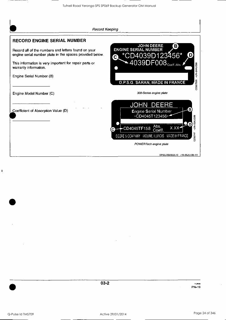
RECORD ENGINE SERIAL NUMBER
Record all of the numbers and letters found on your engine serial number plate in the spaces provided below. IA 1 *II 4 D C This information is very important for repair parts or A I 11: warranty information.
B
Engine Serial Number (B)
Engine Model Number (C)
Coefficient of Absorption Value (D)
300-Series engine plate
JOHN DEERE Engine Serial Number -CD4045T123456.
0
DEERE 3, COMPANY MOLINE, ILLINOIS MADE IN FRANCE
POWERTech engine plate
DPSG,CD03523,13 -19-05JUL99-1/1
03-2 112699
PN=19
Tufnell Road Yeronga SPS SP069 Backup Generator OM Manual
Q-Pulse Id TMS709 Active 29/01/2014 Page 24 of 346

Record Keeping
ENGINE OPTION CODES
JOHN DEERE
1
NUMBER CD6068H123456
6068HF158 6.8 L 171EC 1100 1200 1300 1400 1500 1600 1700 1800 1900 2100 2300 2400 2500 2700 2800 2900 3000 3100 3500 4000 4300 5200 5500 5600 5700 6000 6200 6400 6500 6600 7500 7600 8600 8700 8800
Order: 2B0000000 000000 OPTION CODES
Engine option code label
In addition to the serial number plate, OEM engines have an engine option code label affixed to the rocker arm cover. These codes indicate which of the engine options were installed on your engine at the factory. When in need of parts or service, furnish your authorized servicing dealer or engine distributor with these numbers.
An additional sticker may be also delivered (in a plastic bag attached to the engine or inserted in the machine documentation). It is recommended to stick this option code list sticker either:
On this page of your Operator's manual below this section.
or On the "Engine Owner's Warranty" booklet under the title OPTION CODES (Engine manufacturing configuration).
NOTE: The Machine Manufacturer may have already stuck it at a specific accessible place (inside the enclosure or close to a maintenance area).
The engine option code label includes an engine base code (A). This base code must also be recorded along with the option codes. At times it will be necessary to furnish this base code to differentiate two identical option codes for the same engine model.
The first two digits of each code identify a specific group, such as alternators. The last two digits of each code identify one specific option provided on your engine, such as a 12-volt, 55-amp alternator.
NOTE: These option codes are based on the latest information available at the time of publication. The right is reserved to make changes at any time without notice.
If an engine is ordered without a particular component, the last two digits of that functional group option code will be 99, 00, or XX. The list on the next page shows only the first two digits of the code numbers. For future reference such as ordering repair parts, it is important to have these code numbers available. To ensure this availability, enter the third and fourth digits shown on your engine option code label in the spaces provided on the following page.
NOTE: Your engine option code label may not contain all option codes if an option has been added after the engine left the producing factory.
If option code label is lost or destroyed, consult your servicing dealer or engine distributor selling the engine for a replacement.
Continued on next page DPSG,CD03523,14 -19-05JUL99-1/2
03-3 112699
PN=20
Tufnell Road Yeronga SPS SP069 Backup Generator OM Manual
Q-Pulse Id TMS709 Active 29/01/2014 Page 25 of 346

Record Keeping
Option Codes
Engine Base Code:
Description Option Codes
Description
11 Rocker Arm Cover 45 Balancer Shaft 12 Oil Filler Neck 46 Cylinder Block With Liners and Camshaft 13 Crankshaft Pulley 47 Crankshaft and Bearings 14 Flywheel Housing as Connecting Rods and Pistons 15 Flywheel 49 Valve Actuating Mechanisms 16 Fuel Injection Pump 50 Oil Pump 17 Air inlet 51 Cylinder Head With Valves 18 Air cleaner 52 Auxiliary Gear Drive 19 Oil pan 54 Oil heater 20 Coolant pump 55 Shipping stand 21 Thermostat Cover 56 Paint Option 22 Thermostat 57 Coolant Inlet 23 Fan Drive 59 Oil Cooler 24 Fan Belt 60 Add-on Auxiliary Drive Pulley 25 Fan 62 Alternator Mounting
Engine Coolant Heater 64 Exhaust Elbow Radiator 65 Turbocharger
28 Exhaust Manifold 66 Temperature Switch 29 Ventilator System 67 Electronic Tachometer Sensor 30 Starting Motor 68 Damper 31 Altemator 69 Engine Serial Number Plate 32 Instrument Panel 74 Air Conditioning System Compressor Mounting 35 Fuel Filter 75 Air Restriction Indicator 36 Front Plate 76 Oil Pressure Switch 37 Fuel Transfer Pump 86 Fan Pulley 39 Thermostat Housing 87 Automatic Belt Tensioner 40 Oil Dipstick 88 Oil Filter 41 Belt Driven Front Auxiliary Drive 91 Special Equipment (Factory Installed) 43 Starting Aid 97 Special Equipment (Field Installed) 44 Timing Gear Cover with Gears 98 Shipping
DPSG,CD03523,14 -19-05JUL99-2/2
03-4 112699
PN=21
Tufnell Road Yeronga SPS SP069 Backup Generator OM Manual
Q-Pulse Id TMS709 Active 29/01/2014 Page 26 of 346

Record Keeping
RECORD FUEL INJECTION PUMP MODEL NUMBER
Record the fuel injection pump model and serial information found on the serial number plate (A).
Model No. RPM
Manufacturer's No.
Serial No.
DPSG,CD03523,15 -19-07JUL99-1/1
03-5 112699
PN=22
Tufnell Road Yeronga SPS SP069 Backup Generator OM Manual
Q-Pulse Id TMS709 Active 29/01/2014 Page 27 of 346

Safety RECOGNIZE SAFETY INFORMATION
This is a safety-alert symbol. When you see this symbol on your machine or in this manual, be alert to the potential for personal injury.
Follow recommended precautions and safe operating practices.
co crn
.(33
DX,ALERT -19-29SEP98-1/1
UNDERSTAND SIGNAL WORDS
Wsignal word-DANGER, WARNING, or CAUTION-is ed with the safety-alert symbol. DANGER identifies the
most serious hazards. -
DANGER or WARNING safety signs are located near specific hazards. General precautions are listed on CAUTION safety signs. CAUTION also calls attention to safety messages in this manual.
A DANGER
A WARNING
A CAUTION
DX,SIGNAL -19-03MAR93-1/1
05-1 112699
PN=23
Tufnell Road Yeronga SPS SP069 Backup Generator OM Manual
Q-Pulse Id TMS709 Active 29/01/2014 Page 28 of 346

Safety
ENGINE LIFTING PROCEDURE
A CAUTION: The only recommended method for lifting the engine is with JDG23 Engine Lifting Sling (A) and safety approved lifting straps (B) that come with engine. Use extreme caution when lifting and NEVER permit any part of the body to be positioned under an engine being lifted or suspended.
Lift engine with longitudinal loading on lifting sling and lifting straps only. Angular loading greatly reduces lifting capacity of sling and straps.
NOTE: If engine does not have lifting straps, universal straps can be procured through service parts under part numbers JD-244-1 and JD-244-2.
1. If not equipped, install lifting straps and torque to 200 Nm (145 lb-ft).
2. Attach JDG23 Engine Lifting Sling (A) to engine lifting straps (B) and overhead hoist.
IMPORTANT: Lifting straps are designe'd to lift the engine and accessories such as radiator, air filter and other small components. If larger components, such as power take-off, transmission, generator air compressor... etc, are attached to engine, the lifting straps provided with engine or through parts channel are not intended for this purpose. Technician is responsible for providing adequate lifting devices under these situations. See machine manuals for additional information on removing engine from machine.
3. Carefully move engine to desired location.
DPSG,CD03523,95 -19-060CT99-1/1
05-2 112699
PN=24
Tufnell Road Yeronga SPS SP069 Backup Generator OM Manual
Q-Pulse Id TMS709 Active 29/01/2014 Page 29 of 346

Safety
FOLLOW SAFETY INSTRUCTIONS
Carefully read all safety messages in this manual and on your machine safety signs. Keep safety signs in good condition. Replace missing or damaged safety signs. Be sure new equipment components and repair parts include the current safety signs. Replacement safety signs are available from your John Deere dealer.
Learn how to operate the machine and how to use controls properly. Do not let anyone operate without instruction.
Keep your machine in proper working condition. Unauthorized modifications to the machine may impair the function and/or safety and affect machine life.
you do not understand any part of this manual and need assistance, contact your John Deere dealer.
DX,READ -19-03MAR93-1/1
PREVENT MACHINE RUNAWAY
Avoid possible injury or death from machinery runaway.
Do not start engine by shorting across starter terminals. Machine will start in gear if normal circuitry is bypassed.
NEVER start engine while standing on ground. Start Alkigine only from operator's seat, with transmission in Weutral or park.
DX,BYPAS1 -19-29SEP98-1/1
05-3 112699
PN=25
Tufnell Road Yeronga SPS SP069 Backup Generator OM Manual
Q-Pulse Id TMS709 Active 29/01/2014 Page 30 of 346
Safety
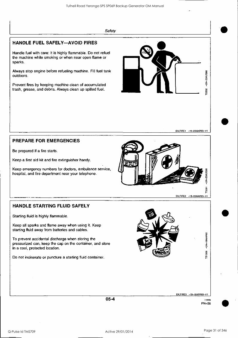
HANDLE FUEL SAFELY-AVOID FIRES
Handle fuel with care: it is highly flammable. Do not refuel the machine while smoking or when near open flame or sparks.
Always stop engine before refueling machine. Fill fuel tank outdoors.
Prevent fires by keeping machine clean of accumulated trash, grease, and debris. Always clean up spilled fuel.
DX,FIREI -19-03MAR93-1/1
PREPARE FOR EMERGENCIES
Be prepared if a fire starts.
Keep a first aid kit and fire extinguisher handy.
Keep emergency numbers for doctors, ambulance service, hospital, and fire department near your telephone.
DX,FIRE2 -I9-03MAR93-1/1
HANDLE STARTING FLUID SAFELY
Starting fluid is highly flammable.
Keep all sparks and flame away when using it. Keep starting fluid away from batteries and cables.
To prevent accidental discharge when storing the pressurized can, keep the cap on the container, and store in a cool, protected location.
Do not incinerate or puncture a starting fluid container.
In
0)
DX,FIRE3 -19-16APR92-1/1
05-4 112699
PN=26
Tufnell Road Yeronga SPS SP069 Backup Generator OM Manual
Q-Pulse Id TMS709 Active 29/01/2014 Page 31 of 346

Safety
WEAR PROTECTIVE CLOTHING
Wear close fitting clothing and safety equipment appropriate to the job.
Prolonged exposure to loud noise can cause impairment or loss of hearing.
Wear a suitable hearing protective device such as earmuffs or earplugs to protect against objectionable or uncomfortable loud noises.
Operating equipment safely requires the full attention of the operator. Do not wear radio or music headphones while operating machine.
<c4Etr...
1
U)
DX,WEAR -19-10SEP90-1/1
PROTECT AGAINST NOISE
Prolonged exposure to loud noise can cause impairment or loss of hearing.
Wear a suitable hearing protective device such as earmuffs or earplugs to protect against objectionable or uncomfortable loud noises.
0
0
DX,NOISE -19-03MAR93-1/1
05-5 112699
PN=27
Tufnell Road Yeronga SPS SP069 Backup Generator OM Manual
Q-Pulse Id TMS709 Active 29/01/2014 Page 32 of 346

Safety
HANDLE CHEMICAL PRODUCTS SAFELY
Direct exposure to hazardous chemicals can cause serious injury. Potentially hazardous chemicals used with John Deere equipment include such items as lubricants, coolants, paints, and adhesives.
A Material Safety Data Sheet (MSDS) provides specific details on chemical products: physical and health hazards, safety procedures, and emergency response techniques.
Check the MSDS before you start any job using a hazardous chemical. That way you will know exactly what the risks are and how to do the job safely. Then follow procedures and recommended equipment.
(See your John Deere dealer for MSDS's on chemical products used with John Deere equipment.)
DX,MSDS,NA -19-03MAF193-1/1
STAY CLEAR OF ROTATING DRIVELINES
Entanglement in rotating driveline can cause serious injury or death.
Keep master shield and driveline shields in place at all times. Make sure rotating shields turn freely.
Wear close fitting clothing. Stop the engine and be sure the PTO driveline is stopped before making adjustments or performing any type service on the engine or PTO-driven equipment.
sz.
CD,PTO -19-12SEP95-1/1
05-6 112699
P N=28
Tufnell Road Yeronga SPS SP069 Backup Generator OM Manual
Q-Pulse Id TMS709 Active 29/01/2014 Page 33 of 346
Safety
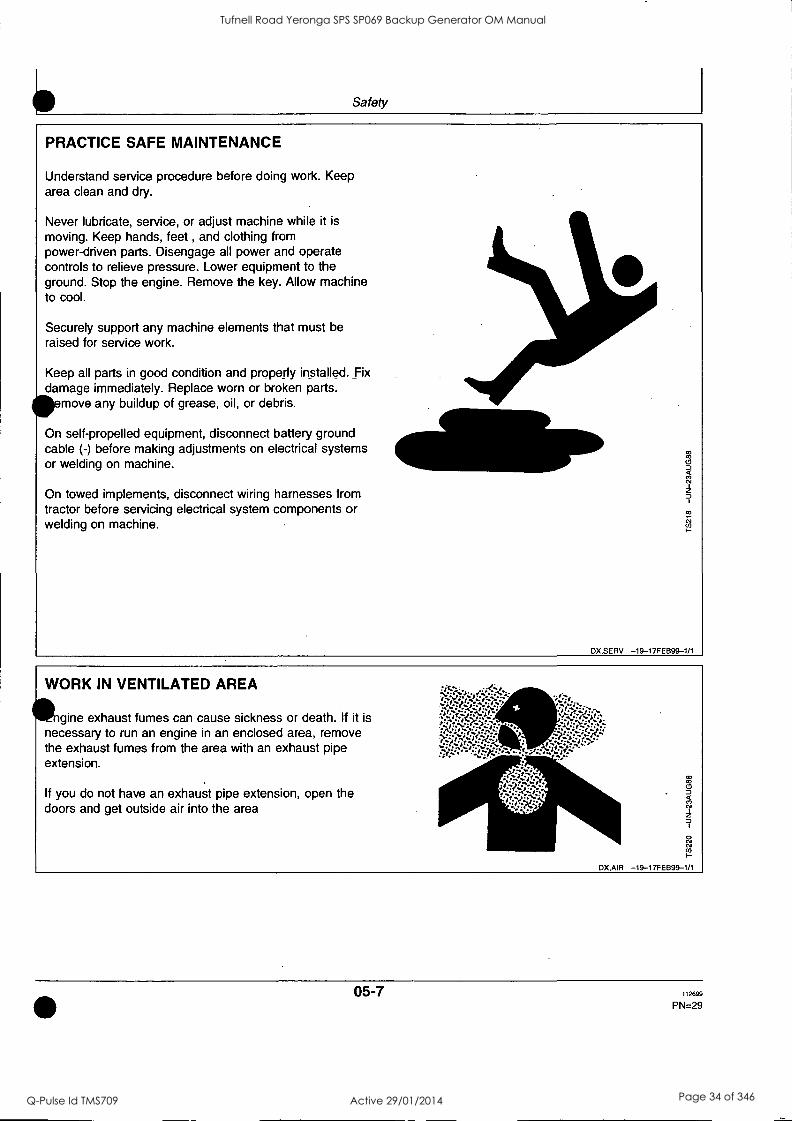
PRACTICE SAFE MAINTENANCE
Understand service procedure before doing work. Keep area clean and dry.
Never lubricate, service, or adjust machine while it is
moving. Keep hands, feet , and clothing from power-driven parts. Disengage all power and operate controls to relieve pressure. Lower equipment to the ground. Stop the engine. Remove the key. Allow machine to cool.
Securely support any machine elements that must be raised for service work.
Keep all parts in good condition and properly installed. Fix damage immediately. Replace worn or broken parts. 4110emove any buildup of grease, oil, or debris.
On self-propelled equipment, disconnect battery ground cable (-) before making adjustments on electrical systems or welding on machine.
On towed implements, disconnect wiring harnesses from tractor before servicing electrical system components or welding on machine.
DX,SERV -19-17FEB99-1/1
WORK IN VENTILATED AREA
Illngine exhaust fumes can cause sickness or death. If it is necessary to run an engine in an enclosed area, remove the exhaust fumes from the area with an exhaust pipe extension.
If you do not have an exhaust pipe extension, open the doors and get outside air into the area
DX,AIR -19-17FEB99-1/1
05-7 112699
PN=29
Tufnell Road Yeronga SPS SP069 Backup Generator OM Manual
Q-Pulse Id TMS709 Active 29/01/2014 Page 34 of 346

Safety
AVOID HIGH-PRESSURE FLUIDS
Escaping fluid under pressure can penetrate the skin causing serious injury.
Avoid the hazard by relieving pressure before disconnecting hydraulic or other lines. Tighten all connections before applying pressure.
Search for leaks with a piece of cardboard. Protect hands and body from high pressure fluids.
If an accident occurs, see a doctor immediately. Any fluid injected into the skin must be surgically removed within a few hours or gangrene may result. Doctors unfamiliar with this type of injury should reference a knowledgeable medical source. Such information is available from Deere & Company Medical Department in Moline, Illinois, U.S.A.
X
DX,FLU ID -19-03MAR93-1/1
AVOID HEATING NEAR PRESSURIZED FLUID LINES
Flammable spray can be generated by heating near pressurized fluid lines, resulting in severe burns to yourself and bystanders. Do not heat by welding, soldering, or using a torch near pressurized fluid lines or other flammable materials. Pressurized lines can be accidentally cut when heat goes beyond the immediate flame area.
=,
# a >-
to I g 7 z D
"...'.
I
Vilik X N el to
U) I-
DX,TORCH -19-03MAR93-1/1
05-8 112699
PN=30
Tufnell Road Yeronga SPS SP069 Backup Generator OM Manual
Q-Pulse Id TMS709 Active 29/01/2014 Page 35 of 346

Safety
REMOVE PAINT BEFORE WELDING OR HEATING
Avoid potentially toxic fumes and dust.
Hazardous fumes can be generated when paint is heated by welding, soldering, or using a torch.
Do all work outside or in a well ventilated area. Dispose of paint and solvent properly.
Remove paint before welding or heating:
If you sand or grind paint, avoid breathing the dust. Wear an approved respirator. If you use solvent or paint stripper, remove stripper with soap and water before welding. Remove solvent or
41111 paint stripper containers and other flammable material from area. Allow fumes to disperse at least 15 minutes before welding or heating.
DX,PAINT -19-03MAR93-1/1
SERVICE COOLING SYSTEM SAFELY
Explosive release of fluids from pressurized cooling system can cause serious burns.
Shut off engine. Only remove filler cap when cool enough to touch with bare hands. Slowly loosen cap to first stop to relieve pressure before removing completely.
DX,RCAP -19-04JUN90-1/1
05-9 112699
PN=31
Tufnell Road Yeronga SPS SP069 Backup Generator OM Manual
Q-Pulse Id TMS709 Active 29/01/2014 Page 36 of 346

Safety
AVOID HARMFUL ASBESTOS DUST
Avoid breathing dust that may be generated when handling components containing asbestos fibers. Inhaled asbestos fibers may cause lung cancer.
Components in products that may contain asbestos fibers are brake pads, brake band and lining assemblies, clutch plates, and some gaskets. The asbestos used in these components is usually found in a resin or sealed in some way. Normal handling is not hazardous as long as airborne dust containing asbestos is not generated.
Avoid creating dust. Never use compressed air for cleaning. Avoid brushing or grinding material containing asbestos. When servicing, wear an approved respirator. A special vacuum cleaner is recommended to clean asbestos. If not available, apply a mist of oil or water on the material containing asbestos.
Keep bystanders away from the area.
DX,DUST -19-15MAR91-1/1
DISPOSE OF WASTE PROPERLY
Improperly disposing of waste can threaten the environment and ecology. Potentially harmful waste used with John Deere equipment include such items as oil, fuel, coolant, brake fluid, filters, and batteries.
Use leakproof containers when draining fluids. Do not use food or beverage containers that may mislead someone into drinking from them.
Do not pour waste onto the ground, down a drain, or into any water source.
Air conditioning refrigerants escaping into the air can damage the Earth's atmosphere. Government regulations may require a certified air conditioning service center to recover and recycle used air conditioning refrigerants.
Inquire on the proper way to recycle or dispose of waste from your local environmental or recycling center, or from your John Deere dealer.
0 0
DX,DRAIN -19-03MAR93-1/1
05-10 112699
PN=32
Tufnell Road Yeronga SPS SP069 Backup Generator OM Manual
Q-Pulse Id TMS709 Active 29/01/2014 Page 37 of 346

Fuels, Lubricants and Coolant DIESEL FUEL
Consult your local fuel distributor for properties of the diesel fuel available in your area.
In general, diesel fuels are blended to satisfy the low temperature requirements of the geographical area in
which they are marketed.
Diesel fuels specified to EN 590 or ASTM D975 are recommended.
In all cases, the fuel shall meet the following properties:
Cetane number of 40 minimum. Cetane number greater than 50 is preferred, especially for
peratures below -20°C (-4°F) or elevations above 00 m (5,000 ft).
Cold Filter Plugging Point (CFPP) below the expected low temperature OR Cloud Point at least 5°C (9°F) below the expected low temperature.
Fuel lubricity should pass a minimum of 3100 gram load level as measured by the BOCLE scuffing test.
Sulfur content:
Sulfur content should not exceed 0.5%. Sulfur content less than 0.05% is preferred. If diesel fuel with sulfur content greater than 0.5% sulfur content is used, reduce the service interval for engine oil and filter by 50%. DO NOT use diesel fuel with sulfur content greater than 1.0%.
Bio-diesel fuels may be used ONLY if the fuel properties meet DIN 51606 or equivalent specification.
DO NOT mix used engine oil or any other type of lubricant with diesel fuel.
DX,FUEL1 -19-17FEB99-1/1
HANDLING AND STORING DIESEL FUEL
ACAUTION: Handle fuel carefully. Do not fill the fuel tank when engine is running.
DO NOT smoke while you fill the fuel tank or service the fuel system.
Fill the fuel tank at the end of each day's operation to prevent condensation and freezing during cold weather.
IMPORTANT: The fuel tank is vented through the filler cap. If a new filler cap is required, always replace it with an original vented cap.
When fuel is stored for an extended period or if there is a slow turnover of fuel, add a fuel conditioner to stabilize the fuel and prevent water condensation. Contact your fuel supplier for recommendations.
DX,FUEL4 -19-18MAR96-1/1
10-1 112699
PN=33
Tufnell Road Yeronga SPS SP069 Backup Generator OM Manual
Q-Pulse Id TMS709 Active 29/01/2014 Page 38 of 346

Fuels, Lubricants and Coolant
ENGINE BREAK-IN OIL
New engines are filled at the factory with John Deere ENGINE BREAK-IN OIL. During the break-in period, add John Deere ENGINE BREAK-IN OIL as needed to maintain the specified oil level.
Change the oil and filter after the first 100 hours of operation of a new or rebuilt engine.
After engine overhaul, fill the engine with John Deere ENGINE BREAK-IN OIL.
If John Deere ENGINE BREAK-IN OIL is not available, use a diesel engine oil meeting one of the following during the first 100 hours of operation:
API Service Classification CE
PLUS-50 is a registered trademark of Deere & Company.
ACEA Specification El
After the break-in period, use John Deere PLUS-50® or other diesel engine oil as recommended in this manual.
IMPORTANT: Do not use PLUS-50 oil or engine oils meeting API CG4, API CF4, ACEA E3, or ACEA E2 performance levels during the first 100 hours of operation of a new or rebuilt engine. These oils will not allow the engine -
to break-in properly.
DX,ENOIL4 -19-100CT97-1/1
10 -2 112699
PN=34
Tufnell Road Yeronga SPS SP069 Backup Generator OM Manual
Q-Pulse Id TMS709 Active 29/01/2014 Page 39 of 346

Fuels, Lubricants and Coolant
DIESEL ENGINE OIL
Use oil viscosity based on the expected air temperature range during the period between oil changes.
The following oil is preferred:
John Deere PLUS -50®
The following oil is also recommended:
John Deere TORQ-GARD SUPREME TORQ-GARD SUPREME®
Other oils may be used if they meet one or more of the following:
API Service Classification CG-4 API Service Classification CF-4 ACEA Specification E3 ACEA Specification E2
Multi-viscosity diesel engine oils are preferred.
If diesel fuel with sulfur content greater than 0.5% is used, reduce the service interval by 50%.
PLUS-50 is a registered trademark of Deere & Company. TORO-GARD SUPREME is a trademark of Deere & Company
11
50°C Ifli 122°F
40°C 104°F
30°C 1141 86°F I 20°C FF11 68 °F
V)
I 10°C
0 °C
-10 °C
-20°C
-30°C
-40°C
50°F
32°F
14°F
-4°F
-22°F
-40°F
CD,ENOIL -19-100CT97-1/1
LUBRICANT STORAGE
our equipment can operate at top efficiency only when clean lubricants are used.
Use clean containers to handle all lubricants.
Whenever possible, store lubricants and containers in
an area protected from dust, moisture, and other contamination. Store containers on their side to avoid water and dirt accumulation.
Make certain that all containers are properly marked to identify their contents.
Properly dispose of all old containers and any residual lubricant they may contain.
DX,LUBST -19-18MAR96-1/1
10-3 112699
PN=35
Tufnell Road Yeronga SPS SP069 Backup Generator OM Manual
Q-Pulse Id TMS709 Active 29/01/2014 Page 40 of 346

Fuels, Lubricants and Coolant
MIXING OF LUBRICANTS
In general, avoid mixing different brands or types of oil. Oil manufacturers blend additives in their oils to meet certain specifications and performance requirements.
Mixing different oils can interfere with the proper functioning of these additives and degrade lubricant performance.
Consult your John Deere dealer to obtain specific information and recommendations.
DX,LUBMIX -19-18MAR96-1/1
DIESEL ENGINE COOLANT
The engine cooling system is filled to provide year-round protection against corrosion and cylinder liner pitting, and winter freeze protection to -37°C (-34°F).
John Deere COOL-GARD is preferred for service.
If John Deere COOL-GARD is not available, use a low silicate ethylene glycol base coolant concentrate in a 50% mixture of concentrate with quality water.
The coolant concentrate shall be of a quality that provides cavitation protection to cast iron and aluminum parts in the cooling system. John Deere COOL-GARD meets this requirement.
A 50% mixture of ethylene glycol engine coolant in water provides freeze protection to -37°C (-34°F). If
protection at lower temperatures is required, consult your John Deere dealer for recommendations.
Water quality is important to the performance of the cooling system. Distilled, deionized, or demineralized
water is recommended for mixing with ethylene glycol base engine coolant concentrate.
IMPORTANT: Do not use cooling system sealing additives or antifreeze that contains sealing additives.
COOLANT DRAIN INTERVALS
Drain the factory fill engine coolant, flush the cooling system, and refill with new coolant after the first 3 years or 3000 hours of operation. Subsequent drain intervals are determined by the coolant used for service. At each interval, drain the coolant, flush the cooling system, and refill with new coolant.
When John Deere COOL-GARD is used, the coolant drain interval is 3 years or 3000 hours of operation.
If COOL-GARD is not used, the drain interval is reduced to 2 years or 2000 hours of operation.
DX,COOL8 -19-12FEB99-1/1
10-4 112699
PN =36
Tufnell Road Yeronga SPS SP069 Backup Generator OM Manual
Q-Pulse Id TMS709 Active 29/01/2014 Page 41 of 346
Fuels, Lubricants and Coolant
OPERATING IN WARM TEMPERATURE CLIMATES
John Deere engines are designed to operate using glycol base engine coolants.
Always use a recommended glycol base engine coolant, even when operating in geographical areas where freeze protection is not required.
IMPORTANT: Water may be used as coolant in emergency situations only.
Foaming, hot surface aluminum and iron corrosion, scaling, and cavitation will occur when water is used as the coolant, even when coolant conditioners are added.
Drain cooling system and refill with recommended glycol base engine coolant as soon as possible.
DX,COOL6 -19-18MAR96-1/1
10-5 112699
PN=37
Tufnell Road Yeronga SPS SP069 Backup Generator OM Manual
Q-Pulse Id TMS709 Active 29/01/2014 Page 42 of 346

Operating the Engine BREAK-IN PERIOD
Within first 100 hours of operation During the first 100 hours of operation, avoid overloading, excessive idling and no-load operation.
See ENGINE BREAK-IN OIL for eventual addition of oil.
NOTE: During the break-in period a higher-than-usual oil consumption should be considered as normal.
After first 100 hours of operation After the first 100 hours, drain the crankcase and
change the oil filter (see CHANGING ENGINE OIL AND FILTER). Fill crankcase with seasonal viscosity grade oil (see DIESEL ENGINE OIL).
Check tension of alternator belt.
Check connections of air intake hoses.
Check for proper tightening of cap screws all around the engine.
DPSG,C D03523,17 -19-09JUL99-1/1
STARTING THE ENGINE
ACAUTION: Before starting engine in a confined building, install proper outlet exhaust ventilation equipment. Always use safety approved fuel storage and piping.
NOTE: If temperature is below 0°C (32°F), it may be necessary to use cold weather starting aids (See COLD WEATHER OPERATION).
1. Perform all prestarting checks outlined in Maintenance/Daily Section.
2. Open the fuel supply shut-off valve, if equipped.
3. Activate the starter motor switch to crank the engine and release it as soon as engine starts.
NOTE: Do not operate the starter motor more than 20 seconds at a time.
D PSG,C D03523,18 -19-09JUL99-1/1
COLD WEATHER OPERATION
Depending on equipment, various cold weather starting aids are available to assist in starting the engine at temperatures below 0°C (32°F).
Continued on next page DPSG,CD03523,19 -19-09JUL99-1/4
15-1 112699
PN=38
Tufnell Road Yeronga SPS SP069 Backup Generator OM Manual
Q-Pulse Id TMS709 Active 29/01/2014 Page 43 of 346

Operating the Engine
Air intake heater
Air intake heater is either a grid-type (A) for POWERTech engines or a glow plug-type (B) for 300-Series engines installed in the air intake channel.
ACAUTION: NEVER use Ether Starting Fluid when air intake heater is used to start the engine.
Activate the heating element (preheater position) for 30 seconds maximum then start the engine.
Coolant heater
Connect plug of coolant heater (A) to a power source (110 or 220 V).
At an ambient temperature of -15°C (5°F), the heating process takes approximatively 2 hours. Extend heating period if ambient temperature is lower.
A
D PSG,C D03523,19 -19-09JUL99-2/4
DPSG,CD03523,19 -19-09JUL99-3/4
Fuel preheater
eel preheater (A) switches ON and OFF automatically in relation to the ambient temperature.
DPSG,C D03523,19 -19-09JUL99-4/4
15-2 112699
PN=39
Tufnell Road Yeronga SPS SP069 Backup Generator OM Manual
Q-Pulse Id TMS709 Active 29/01/2014 Page 44 of 346

Operating the Engine
USING A BOOSTER BATTERY OR CHARGER
A 12-volt booster battery can be connected in parallel with battery(ies) on the unit to aid in cold weather starting. ALWAYS use heavy duty jumper cables.
ACAUTION: Gas given off by batteries is explosive. Keep sparks and flames away from batteries. Before connecting or disconnecting a
battery charger, turn charger off. Make last connection and first disconnection at a point away from battery. Always connect NEGATIVE (-) cable last and disconnect this cable first.
IMPORTANT: Be sure polarity is correct before making connections. Reversed polarity will damage electrical system. Always connect positive to positive and negative to ground. Always use 12-volt booster battery for 12-volt electrical systems and 24-volt booster battery/ batteries for 24-volt electrical systems.
1. Connect booster battery or batteries to produce the required system voltage for your engine application.
NOTE: To avoid sparks, DO NOT allow the free ends of jumper cables to touch the engine.
2. Connect one end of jumper cable to the POSITIVE (+) post of the booster battery.
3. Connect the other end of the jumper cable to the POSITIVE (+) post of battery connected to starter.
4. Connect one end of the other jumper cable to the NEGATIVE (-) post of the booster battery.
5. ALWAYS complete the hookup by making the last connection of the NEGATIVE (-) cable to a good ground on the engine frame and away from the battery(ies).
6. Start the engine. Disconnect jumper cables immediately after engine starts. Disconnect NEGATIVE (-) cable first.
0 0
0
12-Volt System
WM"
24-Volts System
A-12-Volt Machine battery/batteries B-12-Volt Booster battery/batteries C-Booster cable D-Cable to starter motor
DPSG,CD03523,20 -19-09JUL99-1/1
15-3 112699
PN=40
Tufnell Road Yeronga SPS SP069 Backup Generator OM Manual
Q-Pulse Id TMS709 Active 29/01/2014 Page 45 of 346

Operating the Engine
ENGINE OPERATION
Warming engine Operate engine at high idle for 1 to 2 minutes before applying the load.
NOTE: This procedure does not apply to standby generator sets where the engine is loaded immediately upon reaching rated speed.
Normal engine operation Compare engine coolant temperature and engine oil pressure with specifications below:
Minimum oil pressure at full load rated speed'-Specification
Pressure 275 kPa (2.75 bar; 40-psi)-
Coolant temperature range-Specification
Temperature 82°-94°C (180°-202°F)
Stop engine immediately if coolant temperature is above or oil pressure below specifications or if there are any signs of part failure. Symptoms that may be early signs of engine problems could be:
Sudden loss of power
'Oil at normal operating temperature of 115°C (240°F).
Unusual noise or vibration Excessive black exhaust fumes Excessive fuel consumption Excessive oil consumption Fluid leaks
Recommendation for turbocharger engines Should the engine stall when operating under load, IMMEDIATELY restart it to prevent overheating of turbocharger components.
Idling engine Avoid excessive engine idling. Prolonged idling may cause the engine coolant temperature to fall below its normal range. This, in turn, causes crankcase oil dilution, due to incomplete fuel combustion, and permits formation of gummy deposits on valves, pistons and piston rings. It also promotes rapid accumulation of engine sludge and unburned fuel in the exhaust system. If an engine will be idling for more than 5 minutes, stop and restart later.
NOTE: Generator set applications have the governor locked at a specified speed and do not have a slow idle function. These engines idle at no load governed speed (fast idle).
DPSG,CD03523,21 -19-09JUL99-1/1
STANDBY POWER UNITS
To assure that your engine will deliver efficient standby operation when needed, start engine and run at rated speed (with 50%-70% load) for 30 minutes every
2 weeks. DO NOT allow engine to run an extended period of time with no load.
DPSG,CD03523,22 -19-09JUL99-1/1
15-4 112699
PN=41
Tufnell Road Yeronga SPS SP069 Backup Generator OM Manual
Q-Pulse Id TMS709 Active 29/01/2014 Page 46 of 346

Operating the Engine
STOPPING THE ENGINE
1. Before stopping, run engine for at least 2 minutes at fast idle and no load.
2. Stop the engine.
DPSG,CD03523,23 -19-09JUL99-1/1
15-5 112699
PN=42
Tufnell Road Yeronga SPS SP069 Backup Generator OM Manual
Q-Pulse Id TMS709 Active 29/01/2014 Page 47 of 346

Maintenance OBSERVE SERVICE INTERVALS
Using hour meter as a guide, perform all services at the hourly intervals indicated on following pages. At each scheduled maintenance interval, perform all previous maintenance operations in addition to the ones specified. Keep a record of hourly intervals and services performed using charts provided in
Maintenance Records Section.
IMPORTANT: Recommended service intervals are for normal operating conditions. Service MORE OFTEN if engine is operated under adverse conditions. Neglecting maintenance can result in failures or permanent damage to the engine.
DPSG,C D03523,24 -1 9-09JUL99-1 /1
USE CORRECT FUELS, LUBRICANTS AND COOLANT
PORTANT: Use only fuels, lubricants, and coolants meeting specifications outlined in Fuels, Lubricants, and Coolant Section when servicing your John Deere Engine.
Consult your John Deere engine distributor, servicing dealer or your nearest John Deere Parts Network for recommended fuels, lubricants, and coolant. Also available are necessary additives for use when operating engines in tropical, arctic, or any other adverse conditions.
DPSG,C D03523,25 -1 9-09JUL99-1 /1
20-1 112699
PN =43
Tufnell Road Yeronga SPS SP069 Backup Generator OM Manual
Q-Pulse Id TMS709 Active 29/01/2014 Page 48 of 346

Maintenance
MAINTENANCE INTERVAL CHART
Item 10 H / daily
500 H 1000 H / 1 year
2000 H / 2 years
2500 H / 3 years
As required
Check engine oil and coolant level
Check air filter restriction indicator°
Change engine oil and filter"
Replace fuel filter element
Check belt tension and automatic tensioner
Check and adjust valve clearanced
Clean crankcase vent tube
Check air intake hoses, connections and system
Check vibration damper (6 cyL)°
Check engine speed and speed droop govemor
Drain and flush cooling system'
Drain water and sediment from fuel filter
Clean filter element (see note a)
Test thermostat and injection nozzles (see your dealer)9
'Clean air filter element when restriction indicator is red. Replace filter element after 6 cleanings or once a year.
'Change oil and filter after the first 100 hours of operation, then every 500 hours thereafter. Change oil and filter at least once a year.
'Check belt tension every 500 hours on 300-Series engines and on POWERTech engines with manual tensioner. Check automatic belt tensioner every 1000 hours/1 year on POWERTech engines when equipped.
"Have your authorized servicing dealer or engine distributor adjust valve clearance as follows. After the first 500 hours of operation then every 1000 hours thereafter on 300-Series engines. Every 2000 hours on POWERTech engines.
°Have your authorized dealer or engine distributor replace the vibration damper every 4500 hours/5 years.
'Drain and flush cooling system every 2500 hours/3 years when John Deere COOL-GARD coolant is used. Otherwise every 2000 hours/2 years.
Contact your dealer when thermostat or injection nozzles are suspected to be defective. Replace injection nozzles every 5000 hours and thermostat every 10000 hours.
DPSG,CD03523,26 -19-09JUL99-1/1
20-2 112699
PN=44
Tufnell Road Yeronga SPS SP069 Backup Generator OM Manual
Q-Pulse Id TMS709 Active 29/01/2014 Page 49 of 346

Maintenance/Daily or every 10 hours DAILY PRESTARTING CHECKS
POWERTech engine U
Do the following BEFORE STARTING THE ENGINE for the first time each day:
IMPORTANT: DO NOT top up with fresh oil until the oil level is BELOW the add mark.
1. Check engine oil level on dipstick (A). Add as required, using seasonal viscosity grade oil. (See
300-Series engine
FD000047
O
CM
8
DIESEL ENGINE OIL). Add oil at rocker arm cover filler cap (B).
IMPORTANT: DO NOT fill above the crosshatch area. Oil levels anywhere within crosshatch are considered in the acceptable operating range.
Continued on next DPSG,CD03523,27 -19-12JUL99-1/3
25-1 112699
PN=45
Tufnell Road Yeronga SPS SP069 Backup Generator OM Manual
Q-Pulse Id TMS709 Active 29/01/2014 Page 50 of 346

Maintenance/Daily or every 10 hours
(r) / (,) r9
ire /.6%
2.
CAUTION: Explosive release of fluids from ressurized cooling system can cause
serious burns.
Only remove filler cap when engine is cold or when cool enough to touch with bare hands. Slowly loosen cap to first stop to relieve pressure before removing completely.
0 0
Remove radiator cap (E) and check coolant level which should be at bottom of filler neck. Fill radiator with proper coolant solution if level is low. (See DIESEL ENGINE COOLANT). Check overall cooling system for leaks.
DPSG,C D03523,27 -19-12JUL99-2/3
3. If air filter has a dust unloading valve (C), squeeze valve tip to release any trapped dirt particles.
4. Check air intake restriction indicator (D). When indicator is red, air filter needs to be cleaned.
IMPORTANT: Maximum air intake restriction is 6.25 kPa (0.06 bar; 1.0 psi) (25 in. H2O).
A clogged air cleaner element will cause excessive intake restriction and a
reduced air supply to the engine.
5. Make a thorough inspection of the engine compartment.
NOTE: Wipe all fittings, caps and plugs before performing any maintenance to reduce the chance of system contamination.
DPSG,C D03523,27 -19-12JUL99-3/3
25-2 112699
PN=46
Tufnell Road Yeronga SPS SP069 Backup Generator OM Manual
Q-Pulse Id TMS709 Active 29/01/2014 Page 51 of 346

Maintenance/500 hours CHANGING ENGINE OIL AND FILTER
NOTE: Change engine oil and filter for the first time after 100 hours maximum of operation, then every 500 hours thereafter. Change oil and filter at least once a year.
1. Run engine approximately 5 minutes to warm up oil.
Shut engine off.
2. Open oil pan drain valve (A).
3. Drain crankcase oil from engine while warm.
4. Remove and discard oil filter element (B) using a
suitable filter wrench.
Remove oil filter packing and clean filter mounting pad.
IMPORTANT: Filtration of oils is critical to proper lubrication. Always change filter regularly. Use filters meeting John Deere performance specifications.
6. Oil the new packing and install a new filter element. Hand tighten element according to values printed on filter element. If values are not provided, tighten element approximately 3/4 - 1-1/4 turn after packing contacts filter housing. DO NOT overtighten filter element.
7. Close oil pan drain valve.
POWERTEch engine
Continued on next page
300-Series engine
D PSG,C D03523.29 -19-12JUL99--1/2
30-1 112699
PN =47
Tufnell Road Yeronga SPS SP069 Backup Generator OM Manual
Q-Pulse Id TMS709 Active 29/01/2014 Page 52 of 346

Maintenance/500 hours
8. Fill engine crankcase with correct John Deere engine oil through rocker arm cover opening (C); see DIESEL ENGINE OIL.
To determine the correct oil fill quantity for your engine, see "Engine Oil Quantities" in Specifications Section.
NOTE: Crankcase oil capacity may vary slightly. ALWAYS fill crankcase to full mark or within crosshatch on dipstick, whichever is present. DO NOT overfill.
IMPORTANT: Immediately after completing any oil change, crank engine for 30 seconds without permitting engine to start. This will help insure adequate lubrication to engine components before engine starts.
9. Start engine and run to check for possible leaks.
10. Stop engine and check oil level after 10 minutes. If
necessary, top up.
FD000047
DPSG.0 D03523,29 -19-12JUL 99-2/2
30-2 112699
PN=48
Tufnell Road Yeronga SPS SP069 Backup Generator OM Manual
Q-Pulse Id TMS709 Active 29/01/2014 Page 53 of 346

Maintenance/500 hours
REPLACING FUEL FILTER ELEMENT
A-Retaining ring B-Filter element
CAUTION: CAUTION: Escaping fluid under pressure can penetrate the skin causing serious injury. Relieve pressure before disconnecting fuel or other lines. Tighten all connections before applying pressure. Keep hands and body away from pinholes and nozzles which eject fluids under high pressure. Use a piece of cardboard or paper to search for leaks. Do not use your hand.
If any fluid is injected into the skin, it must be surgically removed within a few hours by a doctor familiar with this type injury or gangrene may result. Doctors unfamiliar with this type of injury may call the Deere & Company Medical Department in Moline, Illinois, or other knowledgeable medical source.
4 . Thoroughly clean fuel filter assembly and surrounding area.
2. Loosen drain plug (C) and drain fuel into a suitable container.
NOTE: Lifting up on retaining ring as it is rotated helps to get it past raised locators.
3. Firmly grasp the retaining ring (A) and rotate it
clockwise 1/4 turn. Remove ring with filter element (B).
C-Drain plug D-Bleed plug
IMPORTANT: Do not dump the old fuel into the new filter element. This could cause fuel injection problem.
A plug is provided with the new element for plugging the used element.
4. Inspect filter mounting base for cleanliness. Clean as required.
NOTE: Raised locators on fuel filter canister must be indexed properly with slots in mounting base for correct installation.
5. Install new filter element dry onto mounting base. Be sure element is properly indexed and firmly seated on base. It may be necessary to rotate filter for correct alignment.
6. Install retaining ring onto mounting base making certain dust seal is in place on filter base. Hand tighten ring (about 1/3 turn) until it "snaps" into the detent. DO NOT overtighten retaining ring.
NOTE: The proper installation is indicated when a
"click" is heard and a release of the retaining ring is felt.
7. Bleed the fuel system.
DPSG,CD03523,30 -19-12JUL99-1/1
30-3 112699
PN=49
Tufnell Road Yeronga SPS SP069 Backup Generator OM Manual
Q-Pulse Id TMS709 Active 29/01/2014 Page 54 of 346

Maintenance/500 hours
CHECKING BELT (300-SERIES ENGINES)
1. Inspect belt for cracks, fraying, or stretched out areas. Replace as necessary.
2. Check belt tension using one of following methods:
a) Use of JDG529 Tension Gauge (A)
Belt tension-Specification
New belt 578-622 N (130-140 lb-force) Used belt 378-423 N (85-94 lb-force)
NOTE: Belt is considered used after 10 minutes of operation.
b) Use of tension tester (B) and straight edge (C) A 89 N (20 lb) force applied halfway between pulleys should deflect belt by 19 mm (0.75 in.).
3. If adjustment is necessary, loosen alternator nuts (D) and (E). Pull alternator frame outward until belt is
correctly tensioned.
IMPORTANT: Do not pry against the alternator rear frame. Do not tighten or loosen belts while they are hot.
4. Tighten alternator bracket nuts firmly.
5. Run engine for 10 minutes then recheck belt tension.
DPSG,C D03523,31 -19-12JUL99-1/1
30-4 112699
PN=50
Tufnell Road Yeronga SPS SP069 Backup Generator OM Manual
Q-Pulse Id TMS709 Active 29/01/2014 Page 55 of 346

Maintenance/500 hours
CHECKING BELT (POWERTECH ENGINES WITH MANUAL TENSIONER)
Inspect belt for cracks, fraying, or stretched out areas. Replace if necessary.
NOTE: Belt adjustment is measured using a gauge stamped on the top edge of the alternator bracket.
1. Loosen cap screws (B) and (C).
2. Slide alternator in slot by hand to remove all excess slack in belt.
IMPORTANT: Do not pry against alternator rear frame.
ii. Using the gauge (A) on the alternator bracket, stretch belt by prying outward on alternator front frame. Stretch the belt 1 gauge unit for a used belt and 1.5 gauge units for a new belt.
4. Tighten cap screws (B) and (C).
A-Belt gauge B-Cap screw C-Cap screw
D PSG,C D03523,57 -19-16AUG99-1/1
30-5 112699
PN=51
Tufnell Road Yeronga SPS SP069 Backup Generator OM Manual
Q-Pulse Id TMS709 Active 29/01/2014 Page 56 of 346
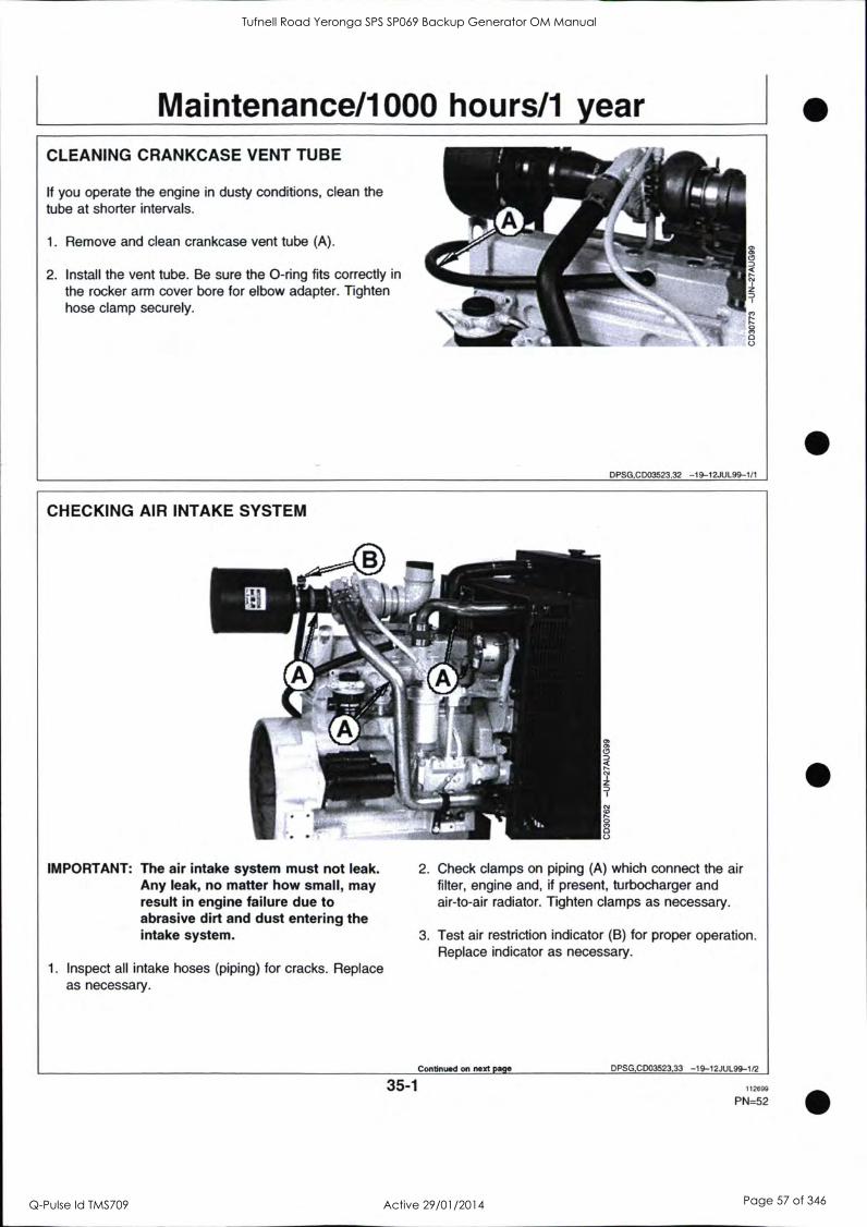
Maintenance/1000 hours/1 year CLEANING CRANKCASE VENT TUBE
If you operate the engine in dusty conditions, clean the tube at shorter intervals.
1. Remove and clean crankcase vent tube (A).
2. Install the vent tube. Be sure the 0-ring fits correctly in
the rocker arm cover bore for elbow adapter. Tighten hose clamp securely.
DPSG,CD03523,32 -19-12JUL99-1/1
CHECKING AIR INTAKE SYSTEM
IMPORTANT: The air intake system must not leak. Any leak, no matter how small, may result in engine failure due to abrasive dirt and dust entering the intake system.
1. Inspect all intake hoses (piping) for cracks. Replace as necessary.
0
2. Check clamps on piping (A) which connect the air filter, engine and, if present, turbocharger and air-to-air radiator. Tighten clamps as necessary.
3. Test air restriction indicator (B) for proper operation. Replace indicator as necessary.
Continued on next page DPSG,CD03523,33 -19-12JUL99-1/2
35-1 112699
PN=52
Tufnell Road Yeronga SPS SP069 Backup Generator OM Manual
Q-Pulse Id TMS709 Active 29/01/2014 Page 57 of 346

Maintenance/1000 hours/1 year
4. If engine has a rubber dust unloading valve (C), inspect the valve on bottom of air filter for cracks or plugging. Replace as necessary.
5. Service air filter as necessary.
b._ MI
DPSG,CD03523,33
. . . . . N
,
Z
, , ,,-
-19-12JUL99-2/2
_...it.)
MP 49
CHECKING AUTOMATIC BELT TENSIONER (POWERTECH ENGINES)
It drive systems equipped with automatic (spring) belt tensioners cannot be adjusted or repaired. The automatic belt tensioner is designed to maintain proper belt tension over the life of the belt. If tensioner spring tension is not within specification, replace tensioner assembly.
Checking belt wear The belt tensioner is designed to operate within the limit of arm movement provided by the cast stops (A) and (B) when correct belt length and geometry is used. If the tensioner stop on swing arm (A) is hitting the fixed stop (B), check mounting brackets (alternator, belt tensioner, idler pulley, etc.) and the belt length. Replace belt as needed (see REPLACING FAN AND ALTERNATOR BELTS).
0
Continued on next page DPSG,CD03523
> 0
z
34 -19-13JUL99-1/2
35-2 112699
PN=53
Tufnell Road Yeronga SPS SP069 Backup Generator OM Manual
Q-Pulse Id TMS709 Active 29/01/2014 Page 58 of 346
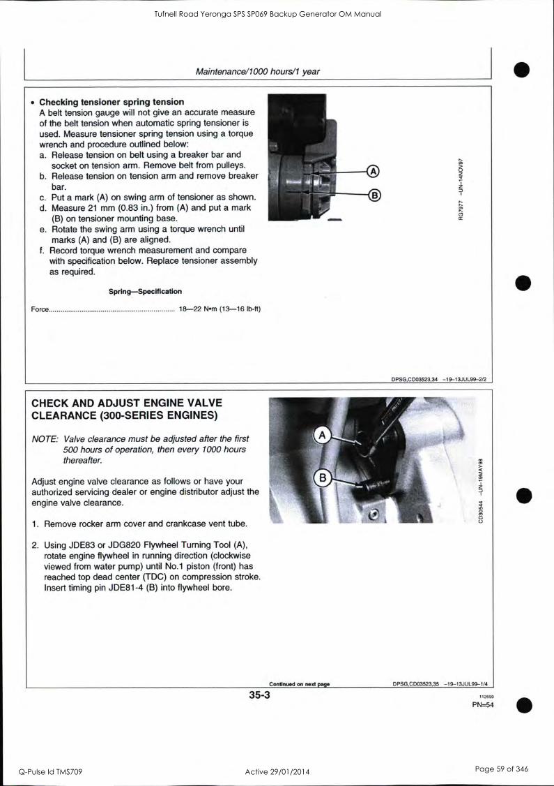
Maintenance/1000 hours/1 year
Checking tensioner spring tension A belt tension gauge will not give an accurate measure of the belt tension when automatic spring tensioner is
used. Measure tensioner spring tension using a torque wrench and procedure outlined below: a. Release tension on belt using a breaker bar and
socket on tension arm. Remove belt from pulleys. b. Release tension on tension arm and remove breaker
bar. c. Put a mark (A) on swing arm of tensioner as shown. d. Measure 21 mm (0.83 in.) from (A) and put a mark
(B) on tensioner mounting base. e. Rotate the swing arm using a torque wrench until
marks (A) and (B) are aligned. f. Record torque wrench measurement and compare
with specification below. Replace tensioner assembly as required.
Spring-Specification
Force 18-22 Nom (13-16 lb-ft)
0 0
DPSG,C D03523,34 -19-13JU L 99-2/2
CHECK AND ADJUST ENGINE VALVE CLEARANCE (300-SERIES ENGINES)
NOTE: Valve clearance must be adjusted after the first 500 hours of operation, then every 1000 hours thereafter.
Adjust engine valve clearance as follows or have your authorized servicing dealer or engine distributor adjust the engine valve clearance.
1. Remove rocker arm cover and crankcase vent tube.
2. Using JDE83 or JDG820 Flywheel Turning Tool (A),
rotate engine flywheel in running direction (clockwise viewed from water pump) until No.1 piston (front) has reached top dead center (TDC) on compression stroke. Insert timing pin JDE81-4 (B) into flywheel bore.
Continued on next page DPSG,C D03523,35 -19-13JUL99-1/4
35-3 112699
PN=54
Tufnell Road Yeronga SPS SP069 Backup Generator OM Manual
Q-Pulse Id TMS709 Active 29/01/2014 Page 59 of 346

Maintenance/1000 hours/1 year
3. Check and adjust valve clearance to specifications according to following procedures.
Valve clearance (engine cold)-Specification
Intake 0.35 mm (0.014 in.)
Exhaust 0.45 mm (0.018 in.)
NOTE: If rocker arm is equipped with adjusting screw and lock nut (A), tighten lock nut to 27 Nrn (20 lb-ft) after adjusting valve clearance.
4. Reinstall rocker arm cover and crankcase vent tube.
DPSG,CD03523,35 -19-13JUL99-2/4
3-Cylinder Engine:
NOTE: Firing order is 1-2-3.
a. Lock No. 1 piston at TDC compression stroke (D). b. Adjust valve clearance on No. 1 and 2 exhaust
valves and No.1 and 3 intake valves. c. Rotate flywheel 360°. Lock No. 1 piston at TDC
exhaust stroke (E). d. Adjust valve clearance on No. 3 exhaust valve and
No. 2 intake valve.
A -1111"" 3 2 1
C B C
A-Front of engine B-Exhaust valve C-Intake valve D-No.1 Piston at TDC compression stroke E-No.1 Piston at TDC exhaust stroke
Continued on next page DPSG,CD03523,35 -19-13JUL99-3/4
35-4 112699
PN=55
Tufnell Road Yeronga SPS SP069 Backup Generator OM Manual
Q-Pulse Id TMS709 Active 29/01/2014 Page 60 of 346

Maintenance/1000 hours/1 year
4-Cylinder Engine:
NOTE: Firing order is 1-3-4-2.
a. Lock No. 1 piston at TDC compression stroke (B). b. Adjust valve clearance on No. 1 and 3 exhaust
valves and No.1 and 2 intake valves. c. Rotate flywheel 360°. Lock No. 4 piston at TDC
compression stroke (C). d. Adjust valve clearance on No. 2 and 4 exhaust
valves and No. 3 and 4 intake valves.
4 E
3 E I E
2 1 E
I 4, It A n A A0A A o Flo
'6 6 " 8
A-Front of engine B-No.1 Piston at TDC compression stroke C-No.4 Piston at TDC compression stroke E-Exhaust valve I-Intake valve
DPSG,CD03523,35 -19-13JUL99-4/4
35-5 112699
PN=56
Tufnell Road Yeronga SPS SP069 Backup Generator OM Manual
Q-Pulse Id TMS709 Active 29/01/2014 Page 61 of 346

Maintenance/2000 hours/2 years CHECK AND ADJUST ENGINE VALVE CLEARANCE (POWERTECH ENGINE)
Adjust engine valve clearance as follows or have your authorized servicing dealer or engine distributor adjust the engine valve clearance.
1. Remove rocker arm cover and crankcase vent tube.
2. Using JDE83 or JDG820 Flywheel Turning Tool (A), rotate engine flywheel in running direction (clockwise viewed from water pump) until No.1 piston (front) has reached top dead center (TDC) on compression stroke. Insert timing pin JDE81-4 (B) into flywheel bore.
DPSG,CD03523,36 -19-13JUL99-1/4
3. Check and adjust valve clearance to specifications according to following procedures.
Valve clearance (engine cold)-Specification
Intake 0.35 mm (0.014 in.) Exhaust 0.45 mm (0.018 in.)
4. If valves need adjusting, loosen the lock nut on rocker arm adjusting screw. Turn adjusting screw until feeler gauge slips with a slight drag. Hold the adjusting screw from turning with screwdriver and tighten lock nut to 27 Nm (20 lb-ft). Recheck clearance again after tightening lock nut. Readjust clearance as necessary
5. Reinstall rocker arm cover and crankcase vent tube.
Continued on next page DPSG,CD03523,36 -19-13JUL99--2/4
40-1 112699
PN=57
Tufnell Road Yeronga SPS SP069 Backup Generator OM Manual
Q-Pulse Id TMS709 Active 29/01/2014 Page 62 of 346

Maintenance/2000 hours/2 years
4-Cylinder Engine:
NOTE: Firing order is 1-3-4-2.
a. Lock No. 1 piston at TDC compression stroke (B). b. Adjust valve clearance on No. 1 and 3 exhaust
valves and No.1 and 2 intake valves. c. Rotate flywheel 360°. Lock No. 4 piston at TDC
compression stroke (C). d. Adjust valve clearance on No. 2 and 4 exhaust
valves and No. 3 and 4 intake valves.
0 to- 4 3 2 1
E I E I E I E I
4 E I
3 E I E
2 1
A-Front of engine B-No.1 Piston at TDC compression stroke C-No.4 Piston at TDC compression stroke E-Exhaust valve I-Intake valve
DPSG,C D03523,36 -19-13JUL99-3/4
6-Cylinder Engine:
NOTE: Firing order is 1-5-3-6-2-4.
a. Lock No. 1 piston at TDC compression stroke (B). b. Adjust valve clearance on No. 1, 3, and 5 exhaust
valves and No. 1, 2, and 4 intake valves. c. Rotate flywheel 360°. Lock No. 6 piston at TDC
compression stroke (C). d. Adjust valve clearance on No. 2, 4, and 6 exhaust
valves and No. 3, 5, and 6 intake valves.
5 4 E I E I E I
3 O
Eli
E I E I E 4 3
E E 2
1
1
E I
A-Front of engine B-No.1 Piston at TDC compression stroke C-No.6 Piston at TDC compression stroke E-Exhaust valve I-Intake valve
D PSG,C D03523,36 -19-13JUL99-4/4
40-2 112699
PN=58
Tufnell Road Yeronga SPS SP069 Backup Generator OM Manual
Q-Pulse Id TMS709 Active 29/01/2014 Page 63 of 346

Maintenance/2000 hours/2 years
CHECKING ENGINE SPEED
NOTE: Most engines for generator set application (1500 rpm for 50 Hz or 1800 rpm for 60 Hz) run only at fast idle and therefore they do not have slow idle.
Fast idle-Specification
50 Hz Generator set 1550-1580 rpm
60 Hz Generator set 1865-1890 rpm
NOTE: Fast idle is settled by the factory then the idle adjusting screw (A) is sealed to prevent from tampering. Fast idle adjustment can only be done by an authorized fuel system agent.
2
DPSG,CD03523,38 -19-13JUL99-1/1
ADJUST SPEED DROOP GOVERNOR
1. Warm engine to normal operating temperature.
2. Run engine at fast idle.
3. Apply full load.
4. If specified power cannot be obtained, turn screw (B) to adjust droop until the requested power is reached.
NOTE: If surging exists upon removing the load, turn screw (B) clockwise to eliminate.
U.
0 0
DPSG,CD03523,39 -19-13JUL99-1/1
40-3 112699
PN=59
Tufnell Road Yeronga SPS SP069 Backup Generator OM Manual
Q-Pulse Id TMS709 Active 29/01/2014 Page 64 of 346

Maintenance/2000 hours/2 years
CHECKING CRANKSHAFT VIBRATION DAMPER (6-CYLINDER ENGINE ONLY)
1. Remove belts (shown removed).
2. Grasp vibration damper with both hands and attempt to turn it in both directions. If rotation is felt, damper is
defective and should be replaced.
IMPORTANT: The vibration damper assembly is not repairable and should be replaced every 4500 hours or 5 years, whichever occurs first.
3. Check vibration damper radial runout by positioning a dial indicator so probe contacts damper outer circumference.
4. With engine at operating temperature, rotate crankshaft using JDG820 or JDE83 Flywheel Turning Tool.
5. Note dial indicator reading. If runout exceeds specifications given below, replace vibration damper.
Damper-Specification
Maximum radial runout 1.50 mm (0.060 in.)
PS G,C D03523,40 -19-13JU L99-1/1
40-4 112699
PN=60
Tufnell Road Yeronga SPS SP069 Backup Generator OM Manual
Q-Pulse Id TMS709 Active 29/01/2014 Page 65 of 346

Maintenance/2500 hours/3 years DRAIN AND FLUSH COOLING SYSTEM
NOTE: Drain and flush cooling system every 2500 hours3 years when John Deere COOL-GARD coolant is used. Otherwise every 2000 hours/2 years.
ACAUTION: Explosive release of fluids from pressurized cooling system can cause serious burns.
Shut off engine. Only remove filler cap when cool enough to touch with bare hands. Slowly loosen cap to first stop to relieve pressure before removing completely.
*Slowly open the radiator cap.
2. Remove engine block drain plug (A).
3. On POWERTech engines, remove oil cooler housing drain plug (B).
4. Open radiator drain valve (C). Drain all coolant from radiator.
5. Close all drain orifices after coolant has drained.
6. Fill the cooling system with clean water. Run engine until water passes through the thermostat to stir up possible rust or sediment.
7. Stop engine and immediately drain the water from system before rust and sediment settle.
8. After draining water, close all drain orifices and fill the cooling system with clean water and TY15979 John ip Deere Heavy Duty Cooling System Cleaner or equivalent cleaner. Follow manufacturer's directions on label.
9. After cleaning the cooling system, drain cleaner and fill with water to flush the system. Run engine until water passes through the thermostat, then drain out flushing water.
II n: rr) r"
, r' (
f , I 7) () t,"? h % i, ;
Continued on next page DPSG,CD03523,41 -19-13JUL99-1/3
45-1 112699
PN=61
Tufnell Road Yeronga SPS SP069 Backup Generator OM Manual
Q-Pulse Id TMS709 Active 29/01/2014 Page 66 of 346

Maintenance/2500 hours/3 years
10. Check cooling system hoses for proper condition. Replace as necessary.
11. Close all drain orifices and fill the cooling system with specified coolant (see DIESEL ENGINE COOLANT).
Cooling system capacity-Specification
CD3029DF128 14.5 L (15.5 qt) CD4039DF008 16.5 L (17.5 qt) CD4039TF008 16.5 L (17.5 qt) CD4045DF158 20 L (21 qt) CD4045HF158 25 L (26.5 qt) CD4045TF158 25 L (26.5 qt) CD4045TF258 25 L (26.5 qt) CD6068HF158 29 L (30.5 qt) CD6068TF158 26 L (27.5 qt) CD6068TF258 26 L (27.5 qt)
DPSG,CD03523,41 -19-13JUL99-2/3
12. When refilling cooling system, loosen temperature sensor (B) or plug at the rear of cylinder head to allow air to escape.
13. Run engine until it reaches operating temperature then check coolant level and entire cooling system for leaks.
of-
-, -.
.
Y.
c)
DPSG,CD03523,41 -19-13JUL99-3/3
45-2 112699
PN=62
Tufnell Road Yeronga SPS SP069 Backup Generator OM Manual
Q-Pulse Id TMS709 Active 29/01/2014 Page 67 of 346

Maintenance/As required ADDITIONAL SERVICE INFORMATION
This manual does not allow a complete repair of your engine. If you want want more detailled service information the following publications are available from your regular parts channel.
PC2451 - Parts Catalog CTM3274 - Component Technical Manual for 300-Series engines (English) CTM104 - Component Technical Manual for POWERTech engines (English) CTM67 - Component Technical Manual for OEM Engine accessories (English only) CTM77 - Component Technical Manual for Alternators and Starter Motors (English only)
D PSG,C D03523,42 -19-15JUL99-1/1
DO NOT MODIFY FUEL SYSTEM
IMPORTANT: Modification or alteration of the injection pump, the injection pump timing, or the fuel injectors in ways not recommended by the manufacturer will terminate the warranty obligation to the purchaser.
Do not attempt to service injection pump or fuel injectors yourself. Special training and special tools are required (see your authorized servicing dealer or engine distributor).
DPSG,CD03523,43 -19-15JUL99-1/1
50-1 112699
P N=63
Tufnell Road Yeronga SPS SP069 Backup Generator OM Manual
Q-Pulse Id TMS709 Active 29/01/2014 Page 68 of 346

Maintenance/As required
CLEAN OR REPLACE AIR FILTER (ONE-PIECE)
Clean air filter when restriction indicator (A) is red. Air filter can be cleaned up to six times. Thereafter, or at least once a year, it must be replaced.
Proceed as follows:
1. Thoroughly clean all dirt around air filter area.
2. Loosen clamp (B) then remove air filter.
IMPORTANT: Never reinstall an air filter which shows evidence of bad condition (punched, dented...) allowing no filtered air to enter the engine.
3. Clean air filter with compressed air working from "clean" to "dirty" side.
NOTE: Compressed air must not exceed 600 kPa (6 bar; 88 psi).
4. Mark air filter to keep track of each cleaning operation.
5. Fully depress air restriction indicator reset button and release to reset indicator.
6. Check air system entirely for proper condition (see CHECKING AIR INTAKE SYSTEM).
I* I
41
DPSG,CD03523,44 -19-15JUL99-1/1
50-2 112699
PN=64
Tufnell Road Yeronga SPS SP069 Backup Generator OM Manual
Q-Pulse Id TMS709 Active 29/01/2014 Page 69 of 346

Maintenance/As required
CLEAN OR REPLACE AIR FILTER ELEMENT
A-Primary element B-Secondary (safety)
element
C-Air restriction indicator D-Wing nut
Clean air filter when restriction indicator (C) is red. Replace both primary (A) and secondary (B) filter elements every 6 primary element cleaning or at least once a year.
Proceed as follows:
1. Thoroughly clean all dirt around air filter area.
Remove wing nut (D) and remove primary element 111, (A) from canister.
IMPORTANT: Do not attempt to clean the secondary (safety) element (B). It must be only replaced as recommended.
3. Thoroughly clean all dirt from inside canister.
IMPORTANT: If primary element shows evidence of bad condition (punched,
dented...), replace both the primary and the secondary elements.
4. Clean primary element with compressed air working from "clean" to "dirty" side.
NOTE: Compressed air must not exceed 600 kPa (6 bar; 88 psi).
5. Mark air filter to keep track of each cleaning operation.
6. Fully depress air restriction indicator reset button and release to reset indicator.
7. Check air system entirely for proper condition (see CHECKING AIR INTAKE SYSTEM).
DPSG,CD03523,58 -19-16AUG99-1/1
50-3 112699
PN=65
Tufnell Road Yeronga SPS SP069 Backup Generator OM Manual
Q-Pulse Id TMS709 Active 29/01/2014 Page 70 of 346

Maintenance/As required
REPLACING FAN AND ALTERNATOR BELT (POWERTECH ENGINES)
NOTE: Refer to CHECKING BELT TENSIONER SPRING TENSION AND BELT WEAR for additional information on the belt tensioner.
1. Inspect belts for cracks, fraying, or stretched out areas. Replace if necessary.
2. On engines with automatic belt tensioner, release tension on belt using a breaker bar and socket on tension arm.
On engines with manual tensioner, loosen cap screws holding the alternator.
3. Remove poly-vee belt from pulleys and discard belt.
4. Install new belt, making sure belt is correctly seated in
all pulley grooves. Refer to belt routing at right for your application.
5. Apply tension to belt (see CHECKING BELT).
6. Start engine and check belt alignment.
00 Installation on 4 cyl. engines
Installation on 6 cyl. engines
ALT-Alternator CP-Crankshaft Pulley FD-Fan Drive I-Idler Pulley T-Tensioner WP-Water Pump
D PSG.0 D03523,45 -19-15JU L 99-1/1
50-4 112699
PN=66
Tufnell Road Yeronga SPS SP069 Backup Generator OM Manual
Q-Pulse Id TMS709 Active 29/01/2014 Page 71 of 346

Maintenance/As required
CHECKING FUEL FILTER
Periodically the fuel filter should be checked for water or
debris.
IMPORTANT: Drain water into a suitable container and dispose of properly.
1. Loosen drain plug (B) at bottom of fuel filter two or
three turns.
2. Loosen air bleed plug two full turns (A) on fuel filter base and drain water from bottom until fuel starts to drain out.
3. When fuel starts to drain out, tighten drain plug securely.
After draining water from the fuel filter, the filter must be primed by bleeding all air from the fuel system. Operate primer lever of the fuel supply pump (C) until fuel flow is free from air bubbles.
5. Tighten bleed plug securely, continue operating hand primer until pumping action is not felt. Push hand primer inward (toward engine) as far as it will go.
If the fuel system needs further bleeding of air, see BLEEDING THE FUEL SYSTEM.
DPSG,CD03523,28 -19-12JUL99-1/1
50-5 112699
PN=67
Tufnell Road Yeronga SPS SP069 Backup Generator OM Manual
Q-Pulse Id TMS709 Active 29/01/2014 Page 72 of 346

Maintenance/As required
BLEEDING THE FUEL SYSTEM
A CAUTION: Escaping fluid under pressure can penetrate the skin causing serious injury. Relieve pressure before disconnecting fuel or other lines. Tighten all connections before applying pressure. Keep hands and body away from pinholes and nozzles which eject fluids under high pressure. Use a piece of cardboard or paper to search for leaks. Do not use your hand.
If ANY fluid is injected into the skin, it must be surgically removed within a few hours by a
doctor familiar with this type injury or gangrene may result. Doctors unfamiliar with this type of injury may call the Deere & Company Medical Department in Moline, Illinois, or other knowledgeable medical source.
Whenever the fuel system has been opened up for service (lines disconnected or filters removed), it will be
necessary to bleed air from the system.
1. Loosen the air bleed screw (A) two full turns by hand on fuel filter base.
2. Operate supply pump primer lever (B) until fuel flow is
free from air bubbles.
3. Tighten bleed plug securely, continue operating hand primer until pumping action is not felt. Push hand primer inward (toward engine) as far as it will go.
4. Start engine and check for leaks.
If engine will not start, it may be necessary to bleed air from fuel system at fuel injection pump or injection nozzles as explained next.
Continued on next page DPSG,C D03523,46 -19-10AUG99-1/2
50-6 112699
P N=68
Tufnell Road Yeronga SPS SP069 Backup Generator OM Manual
Q-Pulse Id TMS709 Active 29/01/2014 Page 73 of 346

Maintenance/As required
At Fuel Injection Pump: a. Slightly loosen fuel return line connector (C) at fuel
injection pump. b. Operate fuel supply pump primer lever until fuel,
without air bubbles, flows from fuel return line connection.
c. Tighten return line connector to 16 Nm (12 lb-ft). d. Leave hand primer in the inward position toward
cylinder block.
At Fuel Injection Nozzles: a. Using two open-end wrenches, loosen fuel line
connection at injection nozzle. b. Crank engine over with starting motor (but do not
start engine), until fuel free from bubbles flows out of loosened connection. Retighten connection to 27 Nrn (20 lb-ft).
oc. Repeat procedure for remaining injection nozzles (if
necessary) until all air has been removed from fuel system.
If engine still will not start, see your authorized servicing dealer or engine distributor.
D PS G,C D03523,46 -19-10AUG99-2/2
50-7 112699
P N=69
Tufnell Road Yeronga SPS SP069 Backup Generator OM Manual
Q-Pulse Id TMS709 Active 29/01/2014 Page 74 of 346
Troubleshooting ENGINE TROUBLESHOOTING
Symptom
Engine cranks but will not start
Engine hard to start or will not start
Problem
Incorrect starting procedure.
No fuel.
Solution
Verify correct starting procedure.
Check fuel in tank and manual shut-off valve.
Exhaust restricted. Check and correct exhaust restriction.
Fuel filter plugged or full of water. Replace fuel filter or drain water from filter.
Injection pump not getting fuel or air Check fuel flow at supply pump or in fuel system. bleed fuel system.
Faulty injection pump or nozzles. Consult authorized diesel repair station for repair or replacement.
Engine starting under load. Remove load.
Improper starting procedure. Review starting procedure.
No fuel. Check fuel tank.
Air in fuel line. Bleed fuel line.
Cold weather. Use cold weather starting aids.
Slow starter speed. See "Starter Cranks Slowly".
Crankcase oil too heavy. Use oil of correct viscosity.
Improper type of fuel. Consult fuel supplier; use proper type fuel for operating conditions.
Water, dirt or air in fuel system. Drain, flush, fill and bleed system.
Clogged fuel filter. Replace filter element.
Dirty or faulty injection nozzles. Have authorized servicing dealer or engine distributor check injectors.
Continued on next page DPSG,CD03523.49 -19- 10AUG99 -1/5
55-1 112699
PN=70
Tufnell Road Yeronga SPS SP069 Backup Generator OM Manual
Q-Pulse Id TMS709 Active 29/01/2014 Page 75 of 346

Troubleshooting
Symptom
Engine knocks
Problem Solution
Injection pump shut-off not reset. Turn key switch to "OFF" then to "ON".
Low engine oil level.
Injection pump out of time.
Low coolant temperature.
Engine overheating.
Engine runs irregularly or stalls Low coolant temperature. frequently
Below normal engine temperature
Lack of power
Clogged fuel filter.
Water, dirt or air in fuel system.
Dirty or faulty injection nozzles.
Defective thermostat.
Defective temperature gauge or sender.
Engine overloaded.
Intake air restriction.
Clogged fuel filter.
Improper type of fuel.
Overheated engine.
Below normal engine temperature.
Improper valve clearance.
Dirty or faulty injection nozzles.
Continued on next page
Add oil to engine crankcase.
See your authorized servicing dealer or engine distributor.
Remove and check thermostat.
See "Engine Overheats".
Remove and check thermostat.
Replace fuel filter element.
Drain, flush, fill and bleed system..
Have authorized servicing dealer or engine distributor check injectors.
Remove and check thermostat.
Check gauge, sender and connections.
Reduce load.
Service air cleaner.
Replace filter element.
Use proper fuel.
See "Engine Overheats".
Remove and check thermostat.
See your authorized servicing dealer or engine distributor.
Have authorized servicing dealer or engine distributor check injectors.
DPSG,CD03523,49 -19-10AUG99-2/5
55-2 112699
PN=71
Tufnell Road Yeronga SPS SP069 Backup Generator OM Manual
Q-Pulse Id TMS709 Active 29/01/2014 Page 76 of 346

Troubleshooting
Symptom
Low oil pressure
High oil consumption
Engine emits white smoke
Problem
Injection pump out of time.
Turbocharger not functioning.
Leaking exhaust manifold gasket.
Defective aneroid control line.
Restricted fuel hose.
Low fast idle speed.
Low oil level.
Improper type of oil.
Crankcase oil too light.
Oil leaks.
Restricted crankcase vent tube.
Defective turbocharger.
Improper type of fuel.
Low engine temperature.
Defective thermostat.
Defective injection nozzles.
Engine out of time.
Continued on next page
Solution
See your authorized or engine distributor.
See your authorized or engine distributor.
See your authorized or engine distributor.
See your authorized or engine distributor.
servicing dealer
servicing dealer
servicing dealer
servicing dealer
Clean or replace fuel hose.
See your authorized servicing dealer or engine distributor.
Add oil.
Drain and fill crankcase with oil of proper viscosity and quality.
Use oil of correct viscosity.
Check for leaks in lines, gaskets, and drain plug.
Clean vent tube.
See your authorized servicing dealer or engine distributor.
Use proper fuel.
Warm up engine to normal operating temperature.
Remove and check thermostat.
See your authorized servicing dealer or engine distributor.
See your authorized servicing dealer or engine distributor.
D PSG,C D03523,49 -19-10AUG99-3/5
55-3 112699
PN=72
Tufnell Road Yeronga SPS SP069 Backup Generator OM Manual
Q-Pulse Id TMS709 Active 29/01/2014 Page 77 of 346

Troubleshooting
Symptom Problem
Engine emits black or grey Improper type of fuel. exhaust smoke
gine overheats
High fuel consumption
Clogged or dirty air cleaner.
Engine overloaded.
Injection nozzles dirty.
Engine out of time.
Turbocharger not functioning.
Engine overloaded.
Low coolant level.
Faulty radiator cap.
Stretched poly-vee belt or defective belt tensioner.
Low engine oil level.
Cooling system needs flushing.
Defective thermostat.
Defective temperature gauge or sender.
Incorrect grade of fuel.
Improper type of fuel.
Clogged or dirty air cleaner.
Continued on next page
Solution
Use proper fuel.
Service air cleaner.
Reduce load.
See your authorized or engine distributor.
See your authorized or engine distributor.
See your authorized or engine distributor.
Reduce load.
servicing dealer
servicing dealer
servicing dealer
Fill radiator to proper level, check radiator and hoses for loose connections or leaks.
Have serviceman check.
Check automatic belt tensioner and - check belts for stretching. Replace
as required.
Check oil level. Add oil as required.
Flush cooling system.
Remove and check thermostat.
Check coolant temperature with thermometer and replace, if
necessary.
Use correct grade of fuel.
Use proper type of fuel.
Service air cleaner.
DPSG,CD03523,49 -19-10AUG99-4/5
55-4 112699
PN=73
Tufnell Road Yeronga SPS SP069 Backup Generator OM Manual
Q-Pulse Id TMS709 Active 29/01/2014 Page 78 of 346

Troubleshooting
Symptom Problem
Engine overloaded.
Improper valve clearance.
Injection nozzles dirty.
Engine out of time.
Defective turbocharger.
Low engine temperature.
Solution
Reduce load.
See your authorized or engine distributor.
See your authorized or engine distributor.
See your authorized or engine distributor.
See your authorized or engine distributor.
Check thermostat.
servicing dealer
servicing dealer
servicing dealer
servicing dealer
DPSG,CD03523,49 -19-10AUG99-5/5
55-5 112699
PN=74
Tufnell Road Yeronga SPS SP069 Backup Generator OM Manual
Q-Pulse Id TMS709 Active 29/01/2014 Page 79 of 346

Troubleshooting
ELECTRICAL TROUBLESHOOTING
Symptom
Undercharged system
Battery uses too much water
Battery will not charge
Starter will not crank
Problem
Excessive elebtrical load from added accessories.
Excessive engine idling.
Poor electrical connections on battery, ground strap, starter or alternator.
Defective battery.
Defective alternator.
Cracked battery case.
Defective battery.
Battery charging rate too high.
Loose or corroded connections.
Sulfated or worn-out battery.
Stretched poly-vee belt or defective belt tensioner.
Engine under load
Loose or corroded connections.
Low battery output voltage.
Faulty start circuit relay.
Blown fuse.
Continued on next page
Solution
Remove accessories or install higher output alternator.
Increase engine rpm when heavy electrical load is used.
Inspect and clean as necessary.
Test battery.
Test charging system.
Check for moisture and replace as necessary.
Test battery.
Test charging system.
Clean and tighten connections.
See your authorized servicing dealer or engine distributor.
Adjust belt tension or replace belts.
Remove load
Clean and tighten loose connections.
See your authorized servicing dealer or engine distributor.
See your authorized servicing dealer or engine distributor.
Replace fuse.
DPSG,CD03523,50 -19-10AUG99-1/2
55-6 112699
PN=75
Tufnell Road Yeronga SPS SP069 Backup Generator OM Manual
Q-Pulse Id TMS709 Active 29/01/2014 Page 80 of 346
Troubleshooting
Symptom Problem
Starter cranks slowly
Entire electrical system
Solution
Low battery output. See your authorized servicing dealer or engine distributor.
Crankcase oil too heavy. Use proper viscosity oil.
Loose or corroded connections. Clean and tighten loose connections.
Faulty battery connection. Clean and tighten connections.
Sulfated or worn-out battery. See your authorized servicing dealer or engine distributor.
Blown fuse. Replace fuse.
DPSG,CD03523,50 -19-10AUG99-2/2
55-7 112699
PN=76
Tufnell Road Yeronga SPS SP069 Backup Generator OM Manual
Q-Pulse Id TMS709 Active 29/01/2014 Page 81 of 346

Storage ENGINE STORAGE GUIDELINES
1. John Deere engines can be stored outside for up to three (3) months with no long term preparation IF COVERED BY WATERPROOF COVERING.
2. John Deere engines can be stored in a standard overseas shipping container for up to three (3) months with no long term preparation.
3. John Deere engines can be stored inside, warehoused, for up to six (6) months with no long term preparation.
4. John Deere engines expected to be stored more than six (6)_months, long term storage preparation
MUST BE taken. (See PREPARING ENGINE FOR LONG TERM STORAGE).
5. For John Deere engines not yet installed in
machines, run a line from a container of AR41937 Nude Oil (from AR41785 Engine Storage Kit) to the fuel transfer pump intake, and another line from the fuel return manifold to the tank, so that Nude Oil is circulated through the injection system during cranking.
DPSG,CD03523,51 -19-10AUG99-1 /1
USE AR41785 ENGINE STORAGE KIT
See your John Deere servicing dealer or engine distributor for an AR41785 Engine Storage Kit. Closely follow instructions provided with this kit.
IMPORTANT: Inhibitors can easily change to gas. Seal or tape each opening immediately after adding inhibitor.
DPSG,CD03523,52 -19-10AUG99-1/1
60-1 112699
PN=77
Tufnell Road Yeronga SPS SP069 Backup Generator OM Manual
Q-Pulse Id TMS709 Active 29/01/2014 Page 82 of 346

Storage
PREPARING ENGINE FOR LONG TERM STORAGE
The following storage preparations are good for long term engine storage up to one year. After that, the engine should be started, warmed up, and retreated for an extended storage period.
IMPORTANT: Any time your engine will not be used for over six (6) months, the following recommendations for storing it and removing it from storage will help to minimize corrosion and deterioration. Use the AR41785 Engine Storage Kit. Follow recommended service procedure included with storage kit.
1. Change engine oil and replace filter. Used oil will not give adequate protection. (See CHANGING ENGINE OIL AND FILTER).
2. Service air cleaner. (See CLEAN OR REPLACE AIR FILTER).
3. Draining and flushing of cooling system is not necessary if engine is to be stored only for several months. However, for extended storage periods of a year or longer, it is recommended that the cooling system be drained, flushed, and refilled. Refill with appropriate coolant. (See DIESEL ENGINE COOLANT).
4. Drain fuel tank and add 30 ml (1 oz) of inhibitor to the fuel tank for each 15 L (4 U.S. gal) of tank capacity. Completely drain fuel filter and close fuel valve, if equipped.
5. Add 30 ml (1 oz) of inhibitor to the engine crankcase for each 0.95 L (1 qt) of crankcase oil.
6. Disconnect air intake piping from the manifold. Pour 90 ml (3 oz) of inhibitor into intake system and reconnect the piping.
7. Crank the engine several revolutions with starter (do not allow the engine to start).
8. Remove fan/alternator belt, if desired.
9. Remove and clean battery. Store them in a cool, dry place and keep them fully charged.
10. Clean the exterior of the engine with salt-free water and touchup any scratched or chipped painted surfaces with a good quality paint.
11. Coat all exposed (machined) metal surfaces with grease or corrosion inhibitor if not feasible to paint.
12. Seal all openings on engine with plastic bags and tape supplied in storage kit. Follow instructions supplied in kit.
13. Store the engine in a dry protected place. If
engine must be stored outside, cover it with a waterproof canvas or other suitable protective material and use a strong waterproof tape.
DPSG,C D03523,53 -19-10AUG99-1/1
60-2 112699
PN=78
Tufnell Road Yeronga SPS SP069 Backup Generator OM Manual
Q-Pulse Id TMS709 Active 29/01/2014 Page 83 of 346

Storage
REMOVING ENGINE FROM LONG TERM STORAGE
Refer to the appropriate section for detailed services listed below or have your authorized servicing dealer or engine distributor perform services that you may not be familiar with.
1. Remove all protective coverings from engine. Unseal all openings in engine and remove covering from electrical systems.
2. Remove the battery from storage. Install battery (fully charged) and connect the terminals.
3. Install fan/alternator belt if removed.
4. Fill fuel tank.
ePerform all appropriate prestarting checks. (See DAILY PRESTARTING CHECKS).
IMPORTANT: DO NOT operate starter more than 30 seconds at a time. Wait at least 2 minutes for starter to cool before trying again.
6. Crank engine for 20 seconds with starter (do not allow the engine to start). Wait 2 minutes and crank engine an additional 20 seconds to assure bearing surfaces are adequately lubricated.
7. Start engine and run at no load for several minutes. Warm up carefully and check all gauges before placing engine under load.
8. On the first day of operation after storage, check overall engine for leaks and check all gauges for correct operation.
DPSG,CD03523,54 -19-10AUG99-1/1
60-3 112699
PN =79
Tufnell Road Yeronga SPS SP069 Backup Generator OM Manual
Q-Pulse Id TMS709 Active 29/01/2014 Page 84 of 346

Specifications GENERAL ENGINE SPECIFICATIONS
ITEM
Number of Cylinders
UNIT OF MEASURE 3029DF128
3
4039DF008
4
4039TF008
4
Fuel Diesel Diesel Diesel
Bore mm 106.5 106.5 106.5
Stroke mm 110 110 110
Displacement L 2.9 3.9 3.9
Compression Ratio 17.8:1 17.8:1 17.8:1
POWER' @ kW (hp) 26 (35) 35 (48) 55 (75) 1500 rpm (Prime)
POWER' © kW (hp) 30 (41) 38 (52) 61 (83) 1500 rpm (Standby)
POWER' © kW (hp) 30 (41) 41 (56) 67 (91) 1800 rpm (Prime)
POWER' © kW (hp) 34 (46) 47 (64) 73 (99) 1800 rpm (Standby)
Width (overall) mm 582 588 588
Length (overall) mm 888 1016 1016
Height (overall) mm 931 960 979
Weight (dry)b kg 345 410 455
Engine oil quantity L 6 12 12
Engine coolant quantity
L 14.5 16.5 16.5
With Fan 'Approximate
Continued on next page DPSG,CD03523,55 -19-10AUG99-1/3
65-1 112699
PN=80
Tufnell Road Yeronga SPS SP069 Backup Generator OM Manual
Q-Pulse Id TMS709 Active 29/01/2014 Page 85 of 346

Specifications
ITEM UNIT OF MEASURE 4045HF158 4045TF158 4045TF258 4045DF158
Number of Cylinders 4 4 4 4
Fuel Diesel Diesel Diesel Diesel
Bore
Stroke
Displacement
Compression Ratio
POWERS @
1500 rpm (Prime)
POWERS @
1500 rpm (Standby)
4030WERs @
00 rpm (Prime)
POWERS @
1800 rpm (Standby)
Width (overall)
Length (overall)
Height (overall)
Weight (dry)°
Engine oil quantity
Engine coolant quantity
With Fan bApproximate
mm
mm
L
106.5
127
4.5
17.0:1
106.5
127
4.5
17.0:1
106.5
127
4.5
17.0:1
106.5
127
4.5
17.6:1
kW (hp) 88 (120) 61 (83) 72 (98) 41 (56)
kW (hp) 96 (131) 68 (92) 80 (109) 42 (57)
kW (hp) 108 (147) 72 (98) 80 (109) 48 (65)
kW (hp) 120 (163) 79 (107) 88 (120) 51 (69)
mm 798 668 668 668
mm 1356 1219 1219 1219
mm 1136 1010 1010 1010
kg 446 436 436 391
L 12 12 12 8
L 25 25 25 20
Continued on next page DPSG,CD03523,55 -19-10AUG99-213
65-2 112699
PN=81
Tufnell Road Yeronga SPS SP069 Backup Generator OM Manual
Q-Pulse Id TMS709 Active 29/01/2014 Page 86 of 346

Specifications
ITEM
Number of Cylinders
UNIT OF MEASURE
6068HF158
6
6068TF158
6
6068TF258
6
Fuel Diesel Diesel Diesel
Bore mm 106.5 106.5 106.5
Stroke mm 127 127 127
Displacement L 6.8 6.8 6.8
Compression Ratio 17.0:1 17.0:1 17.0:1
POWERS © 1500 rpm kW (hp) 134 (182) 92 (125) 105 (143) (Prime)
POWERS @ 1500 rpm kW (hp) 148 (201) 101 (137) 116 (158) (Standby)
POWERS © 1800 rpm kW (hp) 164 (223) 108 (147) 124 (169) (Prime)
POWERS @1800 rpm kW (hp) 187 (254) 119 (162) 137 (186) (Standby)
Width (overall) mm 798 668 668
Length (overall) mm 1476 1383 1383
Height (overall) mm 1136 1032 1032
Weight (dry)b kg 613 593 593
Engine oil quantity L 19.5 19.5 19.5
Engine coolant quantity
L 29 26 26
With Fan 'Approximate
DPSG,C D03523,55 -19-10AUG 99-3/3
65-3 112699
PN=82
Tufnell Road Yeronga SPS SP069 Backup Generator OM Manual
Q-Pulse Id TMS709 Active 29/01/2014 Page 87 of 346

Specifications
UNIFIED INCH BOLT AND CAP SCREW TORQUE VALUES
SAE 1 or 2° 5 5.1 5.2 8 8.2
Grade and Head
NO MARK 0 0 0 0 * a Markings
2 5 8 SAE Grade and
-
Nut NO MARK 0 0 0 Markings
Size
/
Grade 1 Grade 2b Grade 5, 5.1, or 5.2 Grade 8 or 8.2
Lubricated* a Drys Lubricateda Drya Lubricated* Drys Lubricateda Drys
Nm lb-ft lb-ft lb-ft lb-ft N -m lb-ft Nm lb-ft Nm lb-ft lb-ft
1/4 3.7 2.8 4.7 3.5 6 4.5 7.5 5.5 9.5 7 12 9 13.5 10 17 12.5 5/16 7.7 5.5 10 7 12 9 15 11 20 15 25 18 28 21 35 26 3/8 14 10 17 13 22 16 27 20 35 26 44 33 50 36 63 46
7/16 22 16 28 20 35 26 44 32 55 41 70 52 80 58 100 75 1/2 33 25 42 31 53 39 67 50 85 63 110 80 120 90 150 115
9/16 48 36 60 45 75 56 95 70 125 90 155 115 175 130 225 160
5/8 67 50 85 62 105 78 135 100 170 125 215 160 240 175 300 225 3/4 120 87 150 110 190 140 240 175 300 225 375 280 425 310 550 400 7/8 190 140 240 175 190 140 240 175 490 360 625 450 700 500 875 650
1 290 210 360 270 290 210 360 270 725 540 925 675 1050 750 . 1300 975 1-1/8 400 300 510 375 400 300 510 375 900 675 1150 850 1450 1075 1850 1350 1-1/4 570 425 725 530 570 425 725 530 1300 950 1650 1200 2050 1500 2600 1950
1-3/8 750 550 950 700 750 550 950 700 1700 1250 2150 1550 2700 2000 3400 2550 1-1/2 1000 725 1250 925 990 725 1250 930 2250 1650 2850 2100 3600 2650 4550 3350
IIITO NOT use these values if a different torque value r tightening procedure is given for a specific
application. Torque values listed are for general use only. Check tightness of fasteners periodically.
Shear bolts are designed to fail under predetermined loads. Always replace shear bolts with identical grade.
a 'Lubricated" means coaled with a lubricant such as engine oil, or fasteners with phosphate and oil coatings. "Dry" means plain or zinc plated without any lubrication.
b Grade 2 applies for hex cap screws (not hex bolts) up to 152 mm (6-in.) long. Grade 1 applies for hex cap screws over 152 mm (6-in.) long, and for all other types of bolts and screws of any length.
Fasteners should be replaced with the same or higher grade. If higher grade fasteners are used, these should only be tightened to the strength of the original.
Make sure fasteners threads are clean and that you properly start thread engagement. This will prevent them from failing when tightening.
Tighten plastic insert or crimped steel-type lock nuts to approximately 50 percent of the dry torque shown in the chart, applied to the nut, not to the bolt head. Tighten toothed or serrated-type lock nuts to the full torque value.
DX,TORQ1 -19-20JUL94-1/1 I-
65-4 112699
PN=83
Tufnell Road Yeronga SPS SP069 Backup Generator OM Manual
Q-Pulse Id TMS709 Active 29/01/2014 Page 88 of 346

Specifications
METRIC BOLT AND CAP SCREW TORQUE VALUES
Properly Class and Head Markings
* 4.8 8.8 9.8 10.9
10.9
12.9
Q 12.9 I 8.8 I I 9.8 I II 10.9 1
11P11
1 12.9 1 II 4.8 II OPT WI OPP OPP
Property Class and Nut , 5
an CI 9 . 0
,
9 10
0 9 i
10
MB
El 0 12
9 INI
c.J 0 . ....-
Class 4.8 Class 8.8 or 9.8 Class 10.9 Class 12.9
Size Lubricateda Drya Lubricateda Drya Lubricateda Drya Lubricateda Drya .
lb-ft N lb-ft Nin lb-ft lb-ft Nm lb-ft lb-ft lb-ft lb-ft I
M6 4.8 3.5 6 4.5 9 6.5 11 8.5 13 9.5 17 12 15 11.5 19 14.5 M8 12 8.5 15 11 22 16 28 20 32 24 40 30 37 28 47 35 M10 23 17 29 21 43 32 55 40 63 47 80 60 75 55 95 70
M12 40 29 50 37 75 55 95 70 110 80 140 105 130 95 165 120 M14 63 47 80 60 120 88 150 110 175 130 225 165 205 150 260 190 M16 100 73 125 92 190 140 240 175 275 200 350 255 320 240 400 .300
M18 135 100 175 125 260 195 330 250 375 275 475 350 440 325 560 410 M20 190 140 240 180 375 275 475 350 530 400 675 500 625 460 800 580 M22 260 190 330 250 510 375 650 475 725 540 925 675 850 625 1075 800
M24 330 250 425 310 650 475 825 600 925 675 1150 850 1075 800 . 1350 1000 M27 490 360 625 450 950 700 1200 875 1350 1000 1700 1250 1600 1150 2000 1500 M30 675 490 850 625 1300 950 1650 1200 1850 1350 2300 1700 2150 1600 2700 2000
M33 900 675 1150 850 1750 1300 2200 1650 2500 1850 3150 2350 2900 2150 3700 2750 M36 1150 850 1450 1075 2250 1650 2850 2100 3200 2350 4050 3000 3750 2750 4750 3500
DO NOT use these values if a different torque value or tightening procedure is given for a specific application. Torque values listed are for general use only. Check tightness of fasteners periodically.
Shear bolts are designed to fail under predetermined loads. Always replace shear bolts with identical property class.
Fasteners should be replaced with the same or higher property class. If higher property class fasteners are used, these should only be tightened to the strength of the original.
3 "Lubricated" means coated with a lubricant such as engine oil, or fasteners with phosphate and oil coatings. "Dry" means plain or zinc plated without any lubrication.
Make sure fasteners threads are clean and that you properly start thread engagement. This will prevent them from failing when tightening.
Tighten plastic insert or crimped steel-type lock nuts to approximately 50 percent of the dry torque shown in the chart, applied to the nut, not to the bolt head. Tighten toothed or serrated-type lock nuts to the full torque value.
DX,TOR02 -19-20JUL94-1 /1
N
65-5 112699
PN=84
Tufnell Road Yeronga SPS SP069 Backup Generator OM Manual
Q-Pulse Id TMS709 Active 29/01/2014 Page 89 of 346

Index
A
Air filter Clean or replace (one-piece) Clean or replace element
Air intake system Checking
B
Belt Check automatic tensioner Check tension Replace (POWERTech)
reak-in engine oil
C
Coolant Diesel engine Drain and flush cooling system Warm temperature climates
Crankcase vent tube Cleaning
Damper Diesel engine oil diesel fuel
Engine oil Break-In Diesel Draining
Engine speed
D
E
F
Fuel filter Replacement
Page
Fuel system
Page
Bleeding 50-6 Fuel
50-2 Diesel 10-1
50-3 Handling and storing 10-1
35-1
Identification views, 01-1 Inch torque values 65-4
35-2 _
30-4 50-4 L 10-2
Lubricant Mixing 10-4 Storage 10-3
10-4 M 45-1 10-5
Maintenance records 02-1
03-1, 35-1 Maintenance
1000 hours/1 year Check and adjust valve clearance
(300-Series) 35-3 Checking air intake system 35-1 Checking automatic belt tensioner
40-4 (POWERTech) 35-2
10-3 Cleaning crankcase vent tube 03-1, 35-1
10-1 2000 hours/2 years Adjust speed droop governor 40-3 Adjust valve clearance (POWERTech) . 40-1 Check engine speed 40-3 Damper check 40-4
2500 hours/3 years Drain and flush cooling system 45-1
10-2 50 hours/2 weeks
10-3 Checking fuel filter 50-5
30-1 500 hours
40-3 Changing engine oil and filter 30-1 Checking belt 30-4 Replace fuel filter 30-3
As required Additional service information 50-1 Clean or replace air filter (one-piece) 50-2 Clean or replace air filter element 50-3
30-3 Do not modify fuel system 50-1
Index-1 112639
PN=1
Tufnell Road Yeronga SPS SP069 Backup Generator OM Manual
Q-Pulse Id TMS709 Active 29/01/2014 Page 90 of 346
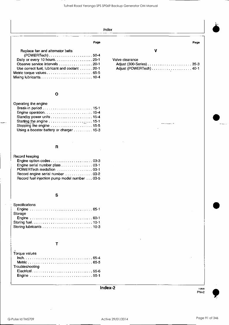
Index
Replace fan and alternator belts
Page
V
Page
(POWERTech) 50-4 Daily or every 10 hours 25-1 Valve clearance Observe service intervals 20-1 Adjust (300-Series) 35-3 Use correct fuel, lubricant and coolant 20-1 Adjust (POWERTech) 40-1
Metric torque values 65-5 Mixing lubricants 10-4
0
Operating the engine Break-in period 15-1
Engine operation 15-4 Standby power units 15-4 Starting the ,engine 15-1 Stopping the engine 15-5 Using a booster battery or charger 15-3
R
Record keeping Engine option codes 03-3 Engine serial number plate 03-1 POWERTech medallion 03-1 Record engine serial number 03-2 Record fuel injection pump model number . .. 03-5
S
Specifications Engine 65-1
Storage Engine 60-1
Storing fuel 10-1 Storing lubricants 10-3
Torque values Inch 65-4 Metric 65-5
Troubleshooting Electrical 55-6 Engine 55-1
Index-2 112699
PN=2
11°
Tufnell Road Yeronga SPS SP069 Backup Generator OM Manual
Q-Pulse Id TMS709 Active 29/01/2014 Page 91 of 346

SPARE PARTS
The spare parts catalogue is too extensive for hard copy presentation.
Please refer to copy on enclosed CD.
Tufnell Road Yeronga SPS SP069 Backup Generator OM Manual
Q-Pulse Id TMS709 Active 29/01/2014 Page 92 of 346

Publication No: 2H-056 22nd Edition
02/01
STA M FORD
NEWAGE INTERNATIONAL
Installation, Service & Maintenance Manual
for AC generators with the following prefixes:
HCI; HCM; HCK 4,5,6,7.
Tufnell Road Yeronga SPS SP069 Backup Generator OM Manual
Q-Pulse Id TMS709 Active 29/01/2014 Page 93 of 346

SAFETY PRECAUTIONS Before operating the generating set, read the generating set operation manual and this generator manual and become familiar with it and the equipment.
SAFE AND EFFICIENT OPERATION CAN ONLY BE ACHIEVED IF THE EQUIPMENT IS CORRECTLY OPERATED AND MAINTAINED.
Many accidents occur because of failure to follow fundamental rules and precautions.
ELECTRICAL SHOCK CAN CAUSE SEVERE PERSONAL INJURY OR DEATH.
Observe all WARNING/CAUTION notices.
Ensure installation meets all applicable safety and local electrical codes. Have all installations performed by a qualified electrician.
Do not operate the generator with protective covers, access covers or terminal box covers removed.
Disable engine starting circuits before carrying out maintenance.
Disable closing circuits and/or place warning notices on any circuit breakers normally used for connection to the mains or other generators, to avoid accidental closure.
Observe all IMPORTANT, CAUTION, WARNING, and DANGER notices, defined as:
Important ! Important refers to hazard or unsafe method or practice which can result in product damage or related equipment damage.
Caution ! Caution refers to hazard or unsafe method or practice which can result in product damage or personal injury.
Warning !
Warning refers to a hazard or unsafe method or practice which CAN result in severe personal injury or possible death.
Danger !
Danger refers to immediate hazards which WILL result in severe personal injury or death.
Due to our policy of continuous improvement, details in this manual which were correct at time of printing, may now be due for amendment. Information included must therefore not be regarded as binding.
Front Cover Photograph This photograph is representative only. Several variations are available within the range of generators covered by this manual.
Tufnell Road Yeronga SPS SP069 Backup Generator OM Manual
Q-Pulse Id TMS709 Active 29/01/2014 Page 94 of 346

FOREWORD The function of this book is to provide the user of the Stamford generator with an understanding of the principles of operation, the criteria for which the generator has been designed, and the installation and maintenance procedures. Specific areas where the lack of care or use of incorrect procedures could lead to equipment damage and/or personal injury are highlighted, with WARNING and/or CAUTION notes, and it is important that the contents of this book are read and understood before proceeding to fit or use the generator.
The Service, Sales and technical staff of Newage International are always ready to assist and reference to the company for advice is welcomed.
Warning!
Incorrect installation, operation, servicing or replacement of parts can result in severe personal injury or death, and/or equipment damage. Service personnel must be qualified to - perform electrical and mechanical service.
EC DECLARATION OF INCORPORATION
All Stamford generators are supplied with a declaration of incorporation for the relevant EC legislation, typically in the form of a label as below.
O EC DECLARATION OF INCORPORATION
IN ACCORDANCE WITH THE SUPPLY OF MACHINERY (SAFETY) REGULATIONS 1992 AND THE SUPPLY OF MACHINERY (SAFETY) (AMENDMENT) REGULATIONS 1994
IMPLEMENTING THE EC MACHINERY DIRECTIVE 89/392/EEC AS AMENDED BY 91/368/EEC.
THIS STAMFORD A.G. GENERATOR WAS MANUFACTURED BY OR ON BEHALF OF
NEWAGE INTERNATIONAL LTD BARRACK ROAD STAMFORD LINCOLNSHIRE ENGLAND.
THIS COMPONENT MACHINERY MUST NOT BE PUT INTO SERVICE UNTIL THE MACHINERY INTO WHICH IT IS TO BE INCORPORATED HAS BEEN DECLARED IN
CONFORMITY WITH THE PROVISIONS OF THE SUPPLY OF MACHINERY (SAFETY) REGULATIONS 1995/MACHINERY DIRECTIVE.
FOR AND ON BEHALF OF NEWAGE INTERNATIONAL LIMITED
NAME: LAWRENCE HAYDOCK
POSITION: TECHNICAL DIRECTOR
SIGNATURE:
THIS COMPONENT MACHINERY CARRIES THE CE MARK FOR COMPLIANCE WITH THE STATUTORY REOUIREMENTS FOR THE IMPLEMENTATION OF THE FOLLOWING DIRECTIVES
The EMC Directive 89/336/EEC This Component Machinery shall not be used in the Residential, Commercial and
WARNING! Light Industrial environment unless it also conforms to the relevant standard (EN 50081 - 1) REFER TO FACTORY FOR DETAILS
ii) The Low Voltage Directive 73/23/EEC as amended by 93/68/EEC
CE
1
ELECTROMAGNETIC COMPATIBILITY
Additional Information
European Union Council Directive 89/336/EEC
For installations within the European Union, electrical products must meet the requirements of the above directive, and Newage ac generators are supplied on the basis that:
They are to be used for power-generation or related function.
They are to be applied in one of the following environments:
Portable (open construction - temporary site supply)
Portable (enclosed - temporary site supply)
Containerised (temporary or permanent site supply)
Ship-borne below decks (marine auxiliary power)
Commercial vehicle (road transport / refrigeration etc)
Rail transport (auxiliary power)
Industrial vehicle (earthmoving, cranes etc)
Fixed installation (industrial - factory / process plant)
Fixed installation (residential, commercial and light industrial home / office / health)
Energy management (Combined heat and power and/or peak lopping) Altemative energy schemes
The standard generators are designed to meet the 'industrial' emissions and immunity standards. Where the generator is
required to meet the residential, commercial and light industrial emissions and immunity standards reference should be made to Newage document reference N4/X/011, as additional equipment may be required.
The installation earthing scheme involves connection of the generator frame to the site protective earth conductor using a
minimum practical lead length.
Maintenance and servicing with anything other than factory supplied or authorised parts will invalidate any Newage liability for EMC compliance.
Installation, maintenance and servicing is carried out by adequately trained personnel fully aware of the requirements of the relevant EC directives
Tufnell Road Yeronga SPS SP069 Backup Generator OM Manual
Q-Pulse Id TMS709 Active 29/01/2014 Page 95 of 346

CONTENTS
SAFETY PRECAUTIONS IFC
FOREWORD 1
CONTENTS 2&3
SECTION 1 INTRODUCTION 4
1.1 INTRODUCTION 4 1.2 DESIGNATION 4 1.3 SERIAL NUMBER LOCATION 4 1.4 RATING PLATE AND CE MARK 4
SECTION 2 PRINCIPLE OF OPERATION 5
2.1 SELF-EXCITED AVR CONTROLLED GENERATORS 5 2.2 PERMANENT MAGNET GENERATOR (PMG) EXCITED -
AVR CONTROLLED GENERATORS 5 2.3 AVR ACCESSORIES 5
SECTION 3 APPLICATION OF THE GENERATOR 6
3.1 VIBRATION 7
SECTION 4 INSTALLATION - PART 1 8
4.1 LIFTING 8 4.2 ENGINE TO GENERATOR COUPLING ASSEMBLY 8 4.2.1 TWO BEARING GENERATORS 8 4.2.2 SINGLE BEARING GENERATORS TYPES HC & HCK 8 4.3 EARTHING 9 4.4 PRE-RUNNING CHECKS 9 4.4.1 INSULATION CHECK 9 4.4.2 DIRECTION OF ROTATION 9 4.4.2.1 FAN TYPES 9 4.4.2.2. DIRECTION OF ROTATION 9 4.4.3 VOLTAGE AND FREQUENCY 9 4.4.4 AVR SETTINGS 9 4.4.4.1 TYPE SX440 AVR 10 4.4.4.2 TYPE SX421 AVR 10 4.4.4.3 TYPE MX341 AVR 10 4.4.4.4 TYPE MX321 AVR 11 4.5 GENERATOR SET TESTING 11
4.5.1 TEST METERING/CABLING 11 4.6 INITIAL START-UP 11
4.7 LOAD TESTING 12 4.7.1 AVR ADJUSTMENTS 12 4.7.1.1 UFRO (Under Frequency Roll Off)
(AVR Types SX440, SX421, MX341 and MX321) 13 4.7.1.2 EXC TRIP (Excitation Trip) 13 4.7.1.3 OVERN (Over Voltage) 13 4.7.1.4 TRANSIENT LOAD SWITCHING ADJUSTMENTS 13 4.7.1.5 RAMP 14 4.8 ACCESSORIES 14
SECTION 5 INSTALLATION - PART 2 14
5.1 GENERAL 14 5.2 GLANDING 14 5.3 MAXIMUM TORQUE SETTINGS FOR
CUSTOMER TERMINAL CONNECTIONS 14 5.4 EARTHING 14 5.5 PROTECTION 14 5.6 COMMISSIONING 14
2
Tufnell Road Yeronga SPS SP069 Backup Generator OM Manual
Q-Pulse Id TMS709 Active 29/01/2014 Page 96 of 346

CONTENTS
SECTION 6 ACCESSORIES 15
6.1 REMOTE VOLTAGE ADJUST (ALL AVR TYPES) 15 6.2 PARALLEL OPERATION 15 6.2.1 DROOP 15 6.2.1.1 SETTING PROCEDURE 16 6.2.2 ASTATIC CONTROL 16 6.3 MANUAL VOLTAGE REGULATOR (MVR) -
MX341 and MX321'AVR 16 6.4. OVERVOLTAGE DE-EXCITATION BREAKER
SX421 and MX321 AVR 16 6.4.1 RESETTING THE EXCITATION BREAKER 17 6.5 CURRENT LIMIT - MX321 AVR 17 6.5.1 SETTING PROCEDURE 17 6.6 POWER FACTOR CONTROLLER (PFC3) 17
SECTION 7 SERVICE AND MAINTENANCE 18
7.1 WINDING CONDITION 18 7.1.1 WINDING CONDITION ASSESSMENT 18 7.1.2 METHODS OF DRYING OUT GENERATORS 18 7.2 BEARINGS 19 7.3 AIR FILTERS 21 7.3.1 CLEANING PROCEDURE 21 7.3.2 RECHARGING (CHARGING) 21 7.4 FAULT FINDING 21 7.4.1 SX440 AVR - FAULT FINDING 21 7.4.2 SX421 AVR - FAULT FINDING 21 7.4.3 MX341 AVR - FAULT FINDING 22 7.4.4 MX321 AVR - FAULT FINDING 22 7.4.5 RESIDUAL VOLTAGE CHECK 22 7.4.6 'REFLASHING' TO RESTORE RESIDUAL 22 7.5 SEPARATE EXCITATION TEST PROCEDURE 23 7.5.1 GENERATOR WINDINGS, ROTATING DIODES and
PERMANENT MAGNET GENERATOR (PMG) 23 7.5.1.1 BALANCED MAIN TERMINAL VOLTAGES 23 7.5.1.2 UNBALANCED MAIN TERMINAL VOLTAGES 24 7.5.2 EXCITATION CONTROL TEST 25 7.5.2.1 AVR FUNCTION TEST 25 7.5.3 REMOVAL AND REPLACEMENT OF COMPONENT
ASSEMBLIES 25 7.5.3.1 ANTI-CONDENSATION HEATERS 25 7.3.3.2 REMOVAL OF PERMANENT MAGNET GENERATOR (PMG) 25 7.5.3.3 REMOVAL OF BEARINGS 25 7.5.3.4 MAIN ROTOR ASSEMBLY 29 7.6 RETURNING TO SERVICE 30 7.7 MAINTENANCE OF REGREASABLE BEARINGS 30
SECTION 8 SPARES AND AFTER SALES SERVICE 31
8.1 RECOMMENDED SPARES 31
8.2 AFTER SALES SERVICE 31
3
Tufnell Road Yeronga SPS SP069 Backup Generator OM Manual
Q-Pulse Id TMS709 Active 29/01/2014 Page 97 of 346

1.1 INTRODUCTION
SECTION 1 INTRODUCTION
1.4 RATING PLATE AND CE MARK
The HC range of generators is of brushless rotating field design, available up to 660V at 50 Hz or 60 Hz and built to meet BS5000 Part 3 and international standards.
1500 rpm (50Hz) or 1800 rpm (60Hz) 4 pole generators are available from 200kW to 2000kW in four frame sizes - HC4, HC5, HC6 and HC7.
1000 rpm (50Hz) or 1200 rpm (60Hz) 6 pole generators are available from 224kW to 1300kW in two frame sizes - HC6 and HC7.
Frame sizes HC4 and HC5 may be provided with a stator fed excitation system using SX440 or SX421 AVR, or with the permanent magnet generator (PMG) powered excitation system, using the MX341 or MX321 AVR.
Frames HC6 and HC7 are fitted with the PMG system using the MX321 AVR.
1.2 DESIGNATION
GENERATOR TYPE HC
The generator has been supplied with a self adhesive rating plate label to enable fitting after final assembly and painting. It is intended that this label will be stuck to the outside of the non drive end of the terminal box.
A CE Mark label is also supplied loose for fitment after final assembly and painting. This should be attached to an external surface of the Generator at a suitable location where it will not be obscured by the customer's wiring or other fittings. Before fitting the CE Mark label the genset builder must address the requirements of the relevant EC legislation to ensure the compliance of the genset as a whole. CE compliance will also need to be addressed when installed on site.
The surface in the area where a label is to be stuck must be flat, clean, and any paint finish be fully dry before attempting to attach label. Recommended method for attaching label is peel and fold back sufficient of the backing paper to expose some 20 mm of label adhesive along the edge which is to be located against the sheet metal protrusions. Once this first section of label has been carefully located and stuck into position the backing paper can be progressively removed, as the label is pressed down into position. The adhesive will achieve a permanent bond in 24 hours.
H C I 4 4 4 C 1
HCM5 3 4C H C I 6 3 4 G
H C I 6 3 6 G 2
HC M7 3 4G
SPECIFIC TYPE K = VOLUTED ADAPTOR AND UNI-DIRECTIONAL FAN
INDUSTRIAL = (I) OR MARINE = (M)
FRAME SIZE AND CONTROL TYPE ON HC/MV
NUMBER OF POLES 4, OR 6
CORE LENGTH
NUMBER OF BEARINGS 1 OR 2
1.3 SERIAL NUMBER LOCATION
Each generator has its unique serial number stamped in to the upper section of the drive end frame end-ring.
Inside the terminal box two adhesive rectangular labels-have been fixed, each carrying the generators unique identity number. One label has been fixed to the inside of the terminal box sheet metal work, and the second label fixed to the main frame of the generator.
4
Tufnell Road Yeronga SPS SP069 Backup Generator OM Manual
Q-Pulse Id TMS709 Active 29/01/2014 Page 98 of 346

SECTION 2 PRINCIPLE OF OPERATION
2.1 SELF-EXCITED AVR CONTROLLED GENERATORS
AUTOMATIC VOLTAGE
REGULATOR
F-1-1 EXUTER STATOR
ROTATING DIODES
EXCITER ROTOR
OUTPUT
Li MAIN STATOR
SHAFT
MAIN ROTOR
Fig. 1
The main stator provides power for excitation of the exciter field via the SX440 (or SX421) AVR which is the controlling device governing the level of excitation provided to the exciter field. The AVR responds to a voltage sensing signal derived from the main stator winding. By controlling the low power of the exciter field, control of the high power requirement of the main field is achieved through the rectified output of the exciter armature.
The SX440 AVR senses average voltage on two phases ensuring close regulation. In addition it detects engine speed and provides voltage fall off with speed, below a pre-selected speed (Hz) setting, preventing over-excitation at low engine speeds and softening the effect of load switching to relieve the burden on the engine.
The SX421 AVR in addition to the SX440 features has three phase rms sensing and also provides for over voltage protection when used in conjunction with an external circuit breaker (switchboard mounted).
E.2 PERMANENT MAGNET GENERATOR (PMG) XCITED - AVR CONTROLLED GENERATORS
PMG STATOR
AUTOMATIC VOLTAGE
REGULATOR
ISOLATING TRANSFORMER
(if fitted)
EXCITER STATOR
ROTATING DIODES
OUTPUT
MAIN STATOR
SHAFT
PMG ROTOR
EXCITER ROTOR
Fig. 2
MAIN ROTOR
The permanent magnet generator (PMG) provides power for wexcitation of the exciter field via the AVR MX341 (or MX321) which
s the controlling device governing the level of excitation provided to the exciter field. The AVR responds to a voltage sensing signal derived, via an isolating transformer in the case of MX321 AVR,
5
from the main stator winding. By controlling the low power of the exciter field, control of the high power requirement of the main field is achieved through the rectified output of the exciter armature.
The PMG system provides a constant source of excitation power irrespective of main stator loading and provides high motor starting capability as well as immunity to waveform distortion on the main stator output created by non linear loads, e.g. thyristor controlled dc motor.
The MX341 AVR senses average voltage on two phases ensuring close regulation. In addition it detects engine speed and provides an adjustable voltage fall off with speed, below a
pre-selected speed (Hz) setting, preventing over-excitation at low engine speeds and softening the effect of load switching to relieve the burden on the engine. It also provides over-excitation protection which acts following a time delay, to de-excite the generator in the event of excessive exciter field voltage.
The MX321 provides the protection and engine relief features of the MX341 and additionally incorporates 3 phase rms sensing and over-voltage protection.
The detailed function of all the AVR circuits is covered in the load testing section (subsection 4.7).
2.3 AVR ACCESSORIES
The SX440, SX421, MX341 and MX321 AVRs incorporate circuits which, when used in conjunction with accessories, can provide for parallel operation either with 'droop' or 'astatic' control, VAR/ PF control and in the case of the MX321 AVR, short circuit current limiting.
Function and adjustment of the accessories which can be fitted inside the generator terminal box are covered in the accessories section of this book.
Separate instructions are provided with other accessories available for control panel mounting.
Tufnell Road Yeronga SPS SP069 Backup Generator OM Manual
Q-Pulse Id TMS709 Active 29/01/2014 Page 99 of 346

SECTION 3 APPLICATION OF THE GENERATOR
The generator is supplied as a component part for installation in a generating set. It is not, therefore, practicable to fit all the necessary warning/hazard labels during generator manufacture. The additional labels required are packaged with this Manual, together with a drawing identifying their locations. (see below).
It is the responsibility of the generating set manufacturer to ensure that the correct labels are fitted, and are clearly visible.
UU1ELW
REFER TO SERVICE MANUAL BEFORE REMOVING COVERS
ABNEHMEN DER AI:MEC/GINGEN NUR GFJAAESS HANDBUCH APAVELSUNG
LEGGERE IL LINTUALE DI ASSISTENZA PREMA DI RIMUOVERE I COPERCHI
CONSULTAR MANUAL ANTES DE RETIRAR TNTAS
VOR MANUEL DE SERVICE AVANT DENLEVER LES COUVERCLES
1,1eil JA t.Led I str 16
The generators have been designed for use in a maximum ambient temperature of 40°C, and altitude less than 1000 metres above sea level in accordance with BS5000.
Ambients in excess of 40°C, and altitudes above 1000 metres can be tolerated with reduced ratings - refer to the generator nameplate for rating and ambient.
In the event that the generator is required to operate in an ambient in excess of the nameplate value or at altitudes in excess of 1000 metres above sea level, refer to the factory.
The generators are of air-ventilated screen protected drip-proof design and are not suitable for mounting outdoors unless
6
adequately protected by the use of canopies. Anti-condensation heaters are recommended during storage and for standby duty to ensure winding insulation is maintained in good condition.
When installed in a closed canopy it must be ensured that the ambient temperature of the cooling air to the generator does not exceed that for which the generator has been rated.
The canopy should be designed such that the engine air intake to the canopy is separated from the generator intake, particularly where the radiator cooling fan is required to draw air into the canopy. In addition the generator air intake to the canopy should be designed such that the ingress of moisture is prohibited, preferably by use of a two stage filter.
The air intake/outlet must be suitable for the air flow given in the following table with additional pressure drops less than or equal to those given below:
Frame
Air Flow Additional (intake/outlet) Pressure Drop
50Hz 1500 Rev/Min
60Hz 1800 Rev/Min
HC4 0.48m3/sec 0.58m3/sec 6mm water gauge
1030cfm 1240cfm (0.25")
HCK4 0.68m3/sec 0.83m3/sec 6mm water gauge
1450cfm 1760cfm (0.25")
HC5 1.04m3 /sec 1.31m3/sec 6mm water gauge
2202cfm 2708cfm (0.25")
HCK5 1.23m3/sec 1.59m3/sec 6mm water gauge
2615cfm 3366cfm (0.25")
HC6 1.62m3/sec 1.96m/sec 6mm water gauge
3420cfm 4156cfm (0.25")
HC7 2.64m3/sec 3.17m3/sec 6mm water gauge
5600cfm 6720cfm (0.25")
HCK7 3.0m3/sec 3.70m3/sec 6mm water gauge
6550cfm 7860cfm (0.25")
Table 1
If specified at the time of ordering, HC6 and HC7 generators may be fitted with air filters. Air filters can be supplied factory fitted or as parts for up-fit for the HC4 and HC5 generators. These are oil charged gauze filters and require charging during installation.
Important ! Reduction in cooling air flow or inadequate protection to the generator can result in damage and/or failure of windings.
Dynamic balancing of the generator rotor assembly has been carried out during manufacture in accordance with BS 6861 Part 1 Grade 2.5 to ensure vibration limits of the generator are in accordance with BS 4999 Part 142.
The main vibration frequencies produced by the component generator are as follows:-:
4 pole
6 pole
1500 rpm
1800 rpm
1000 rpm
1200 rpm
25 Hz
30 Hz
16.7 Hz
20 Hz
Tufnell Road Yeronga SPS SP069 Backup Generator OM Manual
Q-Pulse Id TMS709 Active 29/01/2014 Page 100 of 346

3.1 VIBRATION
Ilkibrations generated by the engine are complex and contain harmonics of 1.5, 3, 5 or more times the fundamental frequency of vibration. The generator will be subjected to this vibration, which will result in the generator being subjected to vibration levels higher than those derived from the generator itself. Newage generators are designed to withstand the vibration levels encountered on generating sets built to meet the requirements of ISO 8528-9 and BS5000-3. (Where ISO 8528 is taken to be broad band measurements and BS5000 refers to the predominant frequency of any vibrations on the generating set.)
DEFINITION OF BS5000 -3
Generators shall be capable of continuously withstanding linear vibration levels with amplitudes of 0.25mm between 5Hz and 8Hz and velocities of 9.0mm/s rms between 8 Hz and 200 Hz when measured at any point directly on the carcass or main frame of the machine. These limits refer only to the predominant frequency of vibration of any complex waveform.
DEFINITION OF ISO 8528 -9
ISO 8528-9 refers to a broad band of frequencies, the broad stand is taken to be between 2 Hertz and 300 Hertz. The table elow is an example from ISO 8528 - 9 (value 1). This simplified
table lists the vibration limits by kVA range and speed for acceptable genset operation.
VIBRATION LEVELS AS MEASURED ON THE GENERATOR
Engine. Speed
Mini
SET
OUTPUT kVA
VIBRATION
DISPLACEMENT
mm (mts)
VIBRATION
VELOCITY
nods (rms)
VIBRATION
ACCELERATION
Ws, (rms)
4 POLE
1500 rpm 50 Hz
1800 rpm 60 HZ
5_ 10 kVA - - -
> 10 but
5 50 Kva 0.64 40 25
> 50 but
5 125 kVA 0.4 25 16
> 125 but
5 250 kVA 0.4 25 16
> 250 kVA 0.32 20 13
6 POLE
1000 rpm 50 Hz
1200 rpm 60 Hz
250 but
51250 0.32 20 13
> 1250 0.29 18 11
The 'Broad band' is taken as 2 Hz - 300 Hz.
Table 2
It is the responsibility of the generating set designer to ensure the alignment of the genset, stiffness of the bedframe and mountings are such that the vibration limits as defined above are met.
If the vibration levels of the generating set are not within the parameters quoted above :-
1. Consult the genset builder. The genset builder should address the genset design to reduce the vibration levels as much as possible.
2. Discuss, with Newage, the impact of not meeting the above levels on both bearing and generator life expectancy.
Important ! Exceeding either of the above specifications will have a detrimental effect on the generating set and in particular on the life of the bearings. (See section on bearings). This will invalidate the generator warranty. If you are in any doubt, contact Newage International Limited.
7
In standby applications where the running time is limited and reduced life expectancy is accepted, higher levels than specified in BS5000 can be tolerated, up to a maximum of 18mm/sec.
Two bearing generators require a substantial bedplate with engine/generator mounting pads to ensure a good base for accurate alignment. Close coupling of engine to generator can increase the overall rigidity of the-set. A flexible coupling, designed to suit the specific engine/generator combination, is recommended to minimise torsional effects.
Alignment of single bearing generators is critical and vibration can occur due to the flexing of the flanges between the engine and generator. A substantial bedplate with engine/generator mounting pads is required.
For the purposes of establishing set design the bending moment at the engine flywheel housing to generator adaptor interface should not exceed that given in the table below:-
FRAME BENDING MOMENT
4/5 140 kgm. (1000ft.lbs.) 6/7 275 kgm. (2000ft.Ibs.)
The maximum bending moment of the engine flange must be checked with the engine manufacturer.
Torsional vibrations occur in all engine-driven shaft systems and may be of a magnitude to cause damage at certain critical speeds. It is therefore necessary to consider the torsional vibration effect on the generator shaft and couplings.
It is the responsibility of the generator set manufacturer to ensure compatibility, and for this purpose drawings showing the shaft dimensions and rotor inertias are available for customers to forward to the engine supplier. In the case of single bearing generators coupling details are included.
Important I Torsional incompatibility and/or excessive vibration levels can cause damage or failure of generator and/or engine components.
The standard terminal box is arranged for cable entry on the right hand side looking from the non drive end of the generator. If specified at the time of order cable entry may be arranged on the opposite side.
The terminal box is constructed with removable panels for easy adaptation to suit specific glanding requirements. Within the terminal box there are insulated terminals for line and neutral connections and provision for earthing. Additional earthing points are provided on the generator feet.
Warning !
No earth connections are made on the generator and reference to site regulations for earthing must be made. Incorrect earthing or protection arrangements can result in personal injury or death.
The neutral is NOT connected to the frame.
Fault current curves (decrement curves), together with generator reactance data, are available on request to assist the system designer to select circuit breakers, calculate fault currents and ensure discrimination within the load network.
Warning !
Incorrect installation, service or replacement of parts can result in severe personal injury or death, and/or equipment damage. Service personnel must be qualified to perform electrical and mechanical service.
Tufnell Road Yeronga SPS SP069 Backup Generator OM Manual
Q-Pulse Id TMS709 Active 29/01/2014 Page 101 of 346

4.1 LIFTING
SECTION 4 INSTALLATION - PART I
During the construction of single bearing units it is necessary to align the generator's coupling holes with the engine flywheel holes: it is suggested that two diametrically opposite location dowel pins are fitted to the engine flywheel, over which the generator coupling can slide into final location into the engine flywheel spigot recess. The dowels must be removed and replaced by coupling bolts before the final bolt tightening sequence.
Warning !
Incorrect lifting or inadequate lifting capacity can result in severe personal injury or equipment damage. MINIMUM LIFTING CAPACITY REQUIRED IS AS INDICATED ON THE LIFTING LABEL Generator lifting lugs should not be used for lifting the complete generating set.
Two lifting lugs are provided for use with a shackle and pin type lifting aid. A spreader with chains to ensure that the lift is vertical of suitable length and lifting capacity must be used. Lifting points are designed to position the craneage point as close to the centre of gravity of the generator as possible, but due to design restrictions it is not possible to guarantee that the generator frame will remain horizontal while lifting. Care is therefore needed to avoid personal injury or equipment damage. The correct lifting arrangement is shown on the label attached to the lifting lug. (See sample below).
IMPORTANT
REFER TO SERVICE MANUAL BEFORE REMOVING COVERS. IT IS THE GENERATOR SET MANUFACTURER'S RESPONSIBILITY TO FIT THE SELF ADHESIVE WARNING LABELS SUPPLIED WITH THE GENERATOR. THE LABEL SHEET CAN BE FOUND WITH THE INSTRUCTION BOOK.
.
4411--- Mt 0 .1i
Lii 5
!Nut: LL co i
- OP% 46.- ..... P. .- -.
= il.4 I I 4011
I
Fig. 3
Single bearing generators are supplied fitted with a rotor retaining bar at the drive end of the shaft. Single bearing generators are also fitted with wooden wedges supporting the fan for transit purposes.
Once the bar is removed to couple the rotor to engine, the rotor is free to move in the frame, and care is needed during coupling and alignment to ensure the frame is kept in the horizontal plane.
4.2 ENGINE TO GENERATOR COUPLING ASSEMBLY
During the assembly of the Generator to the Engine it will be necessary to firstly carefully align, then rotate, the combined Generator rotor - Engine crankshaft assembly, as part of the construction process, to allow location, insertion and tightening of the coupling bolts. This requirement to rotate the combined assemblies exists for both single and two bearing units.
8
While fitting and tightening the coupling bolts it will be necessary to rotate the Engine crankshaft - Generator rotor assembly. Care should be taken to ensure that rotation is carried out in an approved manner that ensures safe working practice when reaching inside the machine to insert or tighten coupling bolts, and that no component of the assembly is damaged by non- approved methods of assembly rotation.
Engine Manufacturers have available a proprietary tool designed to enable manual rotation of the crankshaft assembly. This tool must always be used, having been engineered as an approved method of assembly rotation, by engaging the manually driven. pinion with the engine flywheel starter ring-gear.
Danger !
Before working inside the generator, during the aligning and fitting of coupling bolts, care should be taken to lock the assembly to ensure there is no possibility of assembly rotational movement.
4.2.1 TWO BEARING GENERATORS
A flexible coupling should be fitted and aligned in accordance with the coupling manufacturer's instruction.
If a close coupling adaptor is used the alignment of machined faces must be checked by offering the generator up to the engine. Shim the generator feet if necessary. Ensure adaptor guards are fitted after generator/engine assembly is complete. Open coupled sets require a suitable guard, to be provided by the set builder.
Axial loading of the generator bearings should be avoided. Should it be unavoidable contact the factory for advice.
Caution ! Incorrect guarding and/or generator alignment can result in personal injury and/or equipment damage.
4.2.2 SINGLE BEARING GENERATORS TYPES HC & HCK
For transit and storage purposes the generator frame spigot and rotor coupling plates have been coated with a rust preventative. This MUST BE removed before assembly to engine.
A practical method for removal of this coating is to clean the mating surface areas with a de-greasing agent based on a petroleum solvent.
Caution I Care should be taken not to allow any cleaning agent to come into prolonged contact with skin.
Alignment of single bearing generators is critical. If necessary shim the generator feet to ensure alignment of the machined surfaces.
Tufnell Road Yeronga SPS SP069 Backup Generator OM Manual
Q-Pulse Id TMS709 Active 29/01/2014 Page 102 of 346

The sequence of assembly to the engine should generally be es follows: 1. On the engine check the distance from the coupling
mating face on the flywheel to the flywheel housing mating face. This should be within 0.5mm of nominal dimension. This is necessary to ensure that a thrust is not applied to the ac generator bearing or engine bearing.
2. Check that the bolts securing the flexible plates to the coupling hub are tight and locked into position. Refer to Section 7, subsection 7.5.3.4 for tightening torques.
3. Remove covers from the drive end of the generator to gain access to coupling and adaptor bolts. Check coupling joint interfaces are clean and lubricant free.
4. TYPE HC GENERATORS
Check that coupling discs are concentric with adaptor spigot. This can be adjusted by the use of tapered wooden wedges between the fan and adaptor. Alternatively the rotor can be suspended by means of a rope sling through the adaptor opening. - -
Offer the generator to engine and engage both coupling discs and housing spigots at same time, pushing generator towards engine until coupling discs are against flywheel face, and housing spigots located.
TYPE HCK GENERATORS
Screw the two supplied location studs into diametrically opposite engine flywheel tapped holes, about the horizontal centre line. Offer the generator to engine, locating rotor coupling discs over the location studs, pushing generator towards engine until housing spigots locate and coupling discs are against flywheel face.
5. Fit housing and coupling bolts taking care to use heavy gauge washers between coupling bolt head and coupling disc. Tighten bolts evenly around assembly sufficiently to ensure correct alignment.
6.
TYPE HCK GENERATORS
Remove location studs and replace with coupling- flywheel bolts.
Tighten housing bolts.
Tighten coupling disc to flywheel bolts. Refer to engine manufacturers manual for correct tightening torque.
8. TYPE HC GENERATORS
Remove rotor aligning aids, either wooden wedges, or the two M10 set screws and sheet metal wear plates.
Caution ! Incorrect guarding and/or generator alignment can result in personal injury and/or equipment damage.
4.3 EARTHING
The generator frame should be solidly bonded to the generating set bedplate. If antivibration mounts are fitted between the generator frame and its bedplate a suitably rated earth conductor (normally one half of the cross sectional area of the main line cables) should bridge across the antivibration mount.
Warning !
Refer to local regulations to ensure that the correct earthing procedure has been followed.
9
4.4 PRE-RUNNING CHECKS
4.4.1 INSULATION CHECK
Insulation tests should be carried out before running the generating set, both after assembly and after installation on site. (see Section 7.1).
Important ! The windings have been H.V. tested during manufacture and further H.V. testing may degrade the insulation with consequent reduction in operating life. Should it be necessary to demonstrate H.V. testing, for customer acceptance, the tests must be carried out at reduced voltage levels i.e. Test Voltage= 0.8 (2 X Rated Voltage + 1000)
4.4.2 DIRECTION OF ROTATION
4.4.2.1 FAN TYPES.
TYPE HC 4 & 5 GENERATORS.
These machines are fitted with a radial bladed bi-directional - fan, operating within a conventional full height air outlet grills.
TYPE HC 6 & 7 GENERATORS.
These machines are fitted with an inclined bladed fan ,
operating within a conventional full height air outlet grills.
TYPE HCK 4, 5, & 7 GENERATORS.
These machines are fitted with a inclined bladed fan, operating within a voluted drive end adaptor with outlet .grills half thee machine height . Designed to optimise the fans performance.
4.4.2.2 DIRECTION OF ROTATION
TYPE HCK GENERATORS.
These machines have been designed with an improved cooling fan system, incorporating the voluted fan housing. Therefore these machines are suitable only for clockwise rotation, as viewed from the drive end.
TYPE HC GENERATORS.
These machines can be operated in either direction of rotation.
Phase Rotation
HC generators can rotate efficiently in either direction. However phase rotation is fixed for clockwise rotation as viewed from the drive end. If the generator is to be rotated in a counter-clockwise direction it will be necessary for the customers to adjust their cabling to the output terminals accordingly. Refer to the factory for a reverse wiring diagram.
4.4.3 VOLTAGE AND FREQUENCY
Check that the voltage and frequency levels required for the generating set application are as indicated on the generator nameplate.
HC4/5 generators normally have a 12 ends out reconnectable winding. If it is necessary to reconnect the stator for the voltage required, refer to diagrams in the back of this manual.
4.4.4 AVR SETTINGS
To make AVR selections and adjustments remove the AVR cover and refer to 4.4.4.1, 4.4.4.2, 4.4.4.3 or 4.4.4.4 depending upon type of AVR fitted. Reference to the generator nameplate will indicate AVR type (SX440, SX421, MX341 or MX321).
Most of the AVR adjustments are factory set in positions which will give satisfactory performance during initial running tests. Subsequent adjustment may be required to achieve optimum performance of the set under operating conditions. Refer to 'Load Testing' section for details.
Tufnell Road Yeronga SPS SP069 Backup Generator OM Manual
Q-Pulse Id TMS709 Active 29/01/2014 Page 103 of 346

4.4.4.1 TYPE SX440 AVR
The following jumper' connections on the AVR should be checked to ensure they are correctly set for the generating set application.
Refer to Fig. 4a for location of selection links.
1. Frequency selection terminals 50Hz operation 60Hz operation
LINK C-50 LINK C-60
2. Stability selection terminals Frame HC4/5 LINK B-C Frame HC6/7 LINK A-B
3. Sensing selection terminals LINK 2-3 LINK 4-5 LINK 6-7
4. Excitation Interruption Link LINK K1-K2
4.4.4.2 TYPE SX421 AVR
The following jumper' connections on the AVR should be checked to ensure they are correctly set for the generating set application.
Refer to Fig. 4b for location of selection links.
1.Frequency selection terminals 50Hz operation LINK C-50 60Hz operation LINK C-60
2.Stability selection terminals Frame HC4/5 LINK B-C Frame HC6/7 LINK A-B
3. Excitation Interruption Link Linked at auxiliary terminal block. K1-K2
4.4.4.3 TYPE MX341 AVR
The following jumper' connections on the AVR should be checked to ensure they are correctly set for the generating set application.
Refer to Fig. 4c for location of selection links. 4 pole 50Hz operation 4 pole 60Hz operation 6 pole 50Hz operation 6 pole 60Hz operation
2. Stability selection terminals Frame HC4/5 Frame HC6/7
3. Sensing selection terminals
4. Excitation Interruption Link
LINK 2-3 LINK 1-3
NO LINK LINK 1-2
LINK B-C LINK A-B
LINK 2-3 LINK 4-5 LINK 6-7
LINK K1-K2
10
KI -K2 Linked for
normaloperation.
0 1(2 K1 P2 P3 P4 XX X 311 2 2 -1 J L
SX440
TRIM
DROOP
VOLTS
FREQUENCY
INDICATOR ,SELECTION LED
0
a I ®
0 rko A2
SI S2j
2
3
4
5
6
7
L8-
UFRO STABILITY SELECTION
r 0 L50 C so] LC B Ai 0
50Hz Y_Y 60Hz.Y__Y
y__y 90kW -550kW
y_ y OVER 550kW
Fig. 4a
1-01 :1(2 K1 P2
0
SX421
OVERN
D 1E0 El BO B11
0
0
VOLTS
F4)0(x 6 7 8 1 2I L
r L a 0
INDICATOR LED 60Hz
A-1 50Hz A-1,
UFRO
0 a r C 60 I FREQUENCY 60 - - SELECTION
STABILITY SELECTION
DIP D
a
RMS B
STABILITY
DROOP
- \ TRIM
ID C B AI FS1S2A1A2I D D 0
LI LI
Fig. 4b K1 -K2 Linked for norm al operation.
90kW-550kW OVER 550kW
0 LK2 K1 P2 P3 P4 XX X 31
MX341
r22 11-1
TRIM 1A2
DROOP CI :Slu LS21
Fin VOLTS ID 2
3
4
5
6 DIP EXC TRIP 7 a lal L_8
FREQUENCY
INDICATOR /SELECTION
LED
0 UFRO STABILITY SELECTION
0 e i 3 2 1 11:1 llr LC B Al
_
"I" y 4P/60Hz Y__Y 90kW -550kW
y__y 4P/50Hz tj OVER 550kW
6P/60Hz
NO LINK 6P/50Hz
Fig. 4c
Tufnell Road Yeronga SPS SP069 Backup Generator OM Manual
Q-Pulse Id TMS709 Active 29/01/2014 Page 104 of 346
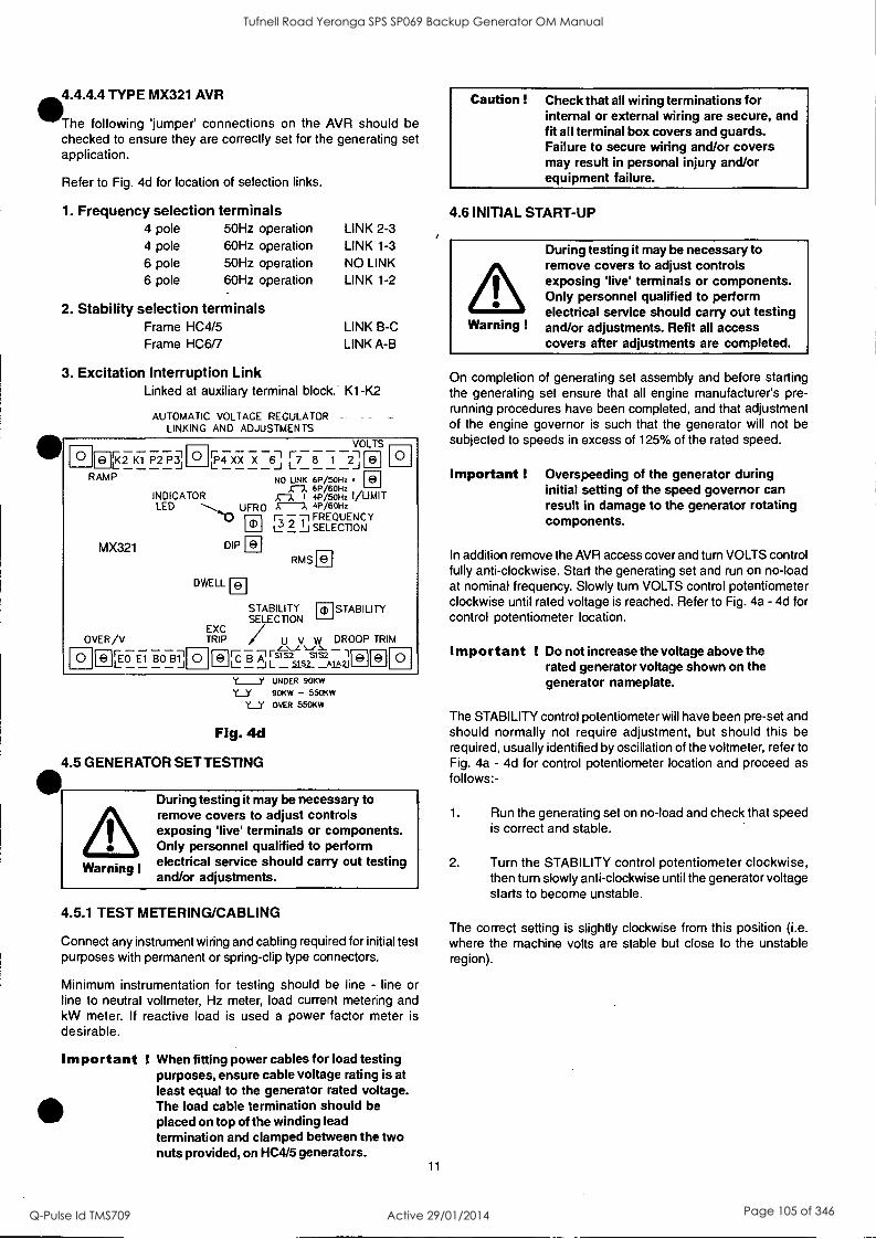
4.4.4.4 TYPE MX321 AVR
The following 'jumper' connections on the AVR should be checked to ensure they are correctly set for the generating set application.
Refer to Fig. 4d for location of selection links.
1. Frequency selection terminals 4 pole 50Hz operation 4 pole 60Hz operation 6 pole 50Hz operation 6 pole 60Hz operation
2. Stability selection terminals Frame HC4/5 Frame HC6/7
LINK 2-3 LINK 1-3
NO LINK LINK 1-2
LINK B-C LINK A-B
3. Excitation Interruption Link Linked at auxiliary terminal block. K1 -K2
AUTOMATIC VOLTAGE REGULATOR - LINKING AND ADJUSTMENTS
0 181 K2 K1 P2 P3 L _J RAMP
MX321
OVER/V
L EO Et BO B1 _ J 0
0 - - - - - - VOLTS
,P4 XX X 6 r
7 8 1 2
NO UNK 6P/50Hz .
INDICATOR 61./6oHz ,
LED A-A 4P/50Hz I/
UFRO 4P /6OHz
--1 FREQUENCY 3 2 1
__I SELECTION
0 a
DIP
DWELL
0
a)
a a
RMS
STABILITY a STABILITY SELECTION
TRIP / w DROOP TRIM
I' Ir EXC
- A SS2 SS 1FL L 51s2 a 0
Y____Y UNDER 90KW
Y__Y 90KW - 550KW
Y__Y OVER 550KW
Fig. 4d
GENERATOR SET TESTING
Warning !
During testing it may be necessary to remove covers to adjust controls exposing 'live' terminals or components. Only personnel qualified to perform electrical service should carry out testing and/or adjustments.
4.5.1 TEST METERING/CABLING
Connect any instrument wiring and cabling required for initial test purposes with permanent or spring-clip type connectors.
Minimum instrumentation for testing should be line - line or line to neutral voltmeter, Hz meter, load current metering and kW meter. If reactive load is used a power factor meter is desirable.
Important When fitting power cables for load testing purposes, ensure cable voltage rating is at least equal to the generator rated voltage. The load cable termination should be placed on top of the winding lead termination and clamped between the two nuts provided, on HC4/5 generators.
11
Caution ! Check that all wiring terminations for internal or external wiring are secure, and fit all terminal box covers and guards. Failure to secure wiring and/or covers may result in personal injury and/or equipment failure.
4.6 INITIAL START-UP
Warning !
During testing it may be necessary to remove covers to adjust controls exposing 'live' terminals or components. Only personnel qualified to perform electrical service should carry out testing and/or adjustments. Refit all access covers after adjustments are completed.
On completion of generating set assembly and before starting the generating set ensure that all engine manufacturer's pre- running procedures have been completed, and that adjustment of the engine governor is such that the generator will not be subjected to speeds in excess of 125% of the rated speed.
Important ! Overspeeding of the generator during initial setting of the speed governor can result in damage to the generator rotating components.
In addition remove the AVR access cover and turn VOLTS control fully anti-clockwise. Start the generating set and run on no-load at nominal frequency. Slowly turn VOLTS control potentiometer clockwise until rated voltage is reached. Refer to Fig. 4a - 4d for control potentiometer location.
Important ! Do not increase the voltage above the rated generator voltage shown on the generator nameplate.
The STABILITY control potentiometer will have been pre-set and should normally not require adjustment, but should this be required, usually identified by oscillation of the voltmeter, refer to Fig. 4a - 4d for control potentiometer location and proceed as follows:-
1. Run the generating set on no-load and check that speed is correct and stable.
2. Turn the STABILITY control potentiometer clockwise, then turn slowly anti-clockwise until the generator voltage starts to become unstable.
The correct setting is slightly clockwise from this position (i.e. where the machine volts are stable but close to the unstable region).
Tufnell Road Yeronga SPS SP069 Backup Generator OM Manual
Q-Pulse Id TMS709 Active 29/01/2014 Page 105 of 346

4.7 LOAD TESTING
Warning !
During testing it may be necessary to remove covers to adjust controls exposing 'live' terminals or components. Only personnel qualified to perform electrical service should carry out testing and/or adjustments. Refit all access covers after adjustments are completed.
4.7.1 AVR ADJUSTMENTS
Refer to Fig. 4a - 4d for control potentiometer locations.
Having adjusted VOLTS and STABILITY during the initial start- up procedure, other AVR control functions should not normally need adjustment. If instability on load is experienced recheck stability setting. Refer to subsection 4.6.
If however, poor voltage regulation on-load or voltage collapse is experienced, refer to the following paragraphs on each function to a) check that the symptoms observed do indicate adjustment is necessary, and b) to make the adjustment correctly.
4.7.1.1 UFRO (Under Frequency Roll Off) (AVR Types SX440, SX421, MX341 and MX321)
The AVR incorporates an underspeed protection circuit which gives a voltage/speed (Hz) characteristic as shown:
>6i
100
95
90
85.
80 75
Clockwise Adjustment
Knee Point
Anticlockwise
Slope shown is typical setting
80 85 90 95 100
% Speed (Hz)
Fig. 5
The UFRO control potentiometer sets the "knee point".
Symptoms of incorrect setting are a) the light emitting diode (LED) indicator, just above the UFRO Control potentiometer, being permanently lit when the generator is on load, and b) poor voltage regulation on load, i.e. operation on the sloping part of the characteristic.
Clockwise adjustment lowers the frequency (speed) setting of the "knee point" and extinguishes the LED. For Optimum setting the LED should illuminate as the frequency falls just below nominal frequency, i.e. 47Hz on a 50Hz generator or 57Hz on a
60Hz generator. 12
Important ! With AVR Types MX341 and MX321. If the LED is illuminated and no output voltage is present, refer to EXC TRIP and/or OVERN sections below.
4.7.1.2 EXC TRIP (Excitation Trip) AVR Types MX341 and MX321
An AVR supplied from a permanent magnet generator inherently delivers maximum excitation power on a line to line or line to neutral short circuit. In order to protect the generator windings the AVR incorporates an over excitation circuit which detects high excitation and removes it after a pre-determined time, i.e. 8-10 seconds.
Symptoms of incorrect setting are the generator output collapses on load or small overload, and the LED is permanently illuminated.
The correct setting is 70 volts +/- 5% between terminals X and )0(
4.7.1.3 OVERN (Over Voltage) AVR Types SX421 and MX321
Over voltage protection circuitry is included in the AVR to remove generator excitation in the event of loss of AVR sensing input.
The MX321 has both internal electronic de-excitation and provision of a signal to operate an external circuit breaker. The SX421 only provides a signal to operate an external breaker, which MUST be fitted if over voltage protection is required. Incorrect setting would cause the generator output voltage to collapse at no-load or on removal of load, and the LED to be illuminated.
The correct setting is 300 volts +/-5% across terminals El, E0.
Clockwise adjustment of the OVERN control potentiometer will increase the voltage at which the circuit operates.
4.7.1.4 TRANSIENT LOAD SWITCHING ADJUSTMENTS AVR Types SX421, MX341 and MX321
The additional function controls of DIP and DWELL are provided to enable the load acceptance capability of the generating set to be optimised. The overall generating set performance depends upon the engine capability and governor response, in conjunction with the generator characteristics.
It is not possible to adjust the level of voltage dip or recovery independently from the engine performance, and there will always be a 'trade off' between frequency dip and voltage dip.
Tufnell Road Yeronga SPS SP069 Backup Generator OM Manual
Q-Pulse Id TMS709 Active 29/01/2014 Page 106 of 346

111,
AmDIP-AVR Types SX421, MX341 and MX321
The dip function control potentiometer adjusts the slope of the voltage/speed (Hz) characteristic below the knee point as shown below:
Knee Point
-6 I
100
95
90
85
80
Adjustable Anticlockwise Adjustment
Slope
Clockwise Adjustment
75 80 85 90 95 100
% Speed (Hz)
Fig. 6
DWELL-AVR Type MX321
The dwell function introduces a time delay between the recovery of voltage and recovery of speed.
The purpose of the time delay is to reduce the generator kW below the available engine kW during the recovery period, thus allowing an improved speed recovery.
Again this control is only functional below the "knee point", i.e. if the speed stays above the knee point during load switching there is no effect from the DWELL function setting.
Clockwise adjustment gives increased recovery time.
a
100
95
90
85
80
Anticlockwise Ad'ustment
Adjustable Slope
11r IM:lockwise
Adjustment
Instant of Load Application
Fig. 7
Time
The graphs shown above are representations only, since it is Oimpossible to show the combined effects of voltage regulator and engine governor performance.
Warning !
Failure to refit covers can result in operator personal injury or death.
4.7.1.5 RAMP AVR Type MX321
The RAMP potentiometer enables adjustment of the time taken for the generator's initial build up to normal rated voltage during each start and run up to speed. The potentiometer is factory set to give a ramp time of three seconds, which is considered to be suitable for most applications. This time can be reduced to one second by turning the pot. fully counter clockwise, and increased to eight seconds by turning the pot. fully clockwise.
4.8 ACCESSORIES
- Refer to the "ACCESSORIES" Section of this Manual for setting up procedures related to generator mounted accessories.
13
If there are accessories for control panel mounting supplied with the generator refer to the specific accessory fitting procedures inserted inside the back cover of this book.
Replace AVR access cover after all adjustments are completed.
Tufnell Road Yeronga SPS SP069 Backup Generator OM Manual
Q-Pulse Id TMS709 Active 29/01/2014 Page 107 of 346

5.1 GENERAL
SECTION 5 INSTALLATION - PART 2
The following table is for your guidance.
The extent of site installation will depend upon the generating set build, e.g. if the generator is installed in a canopied set with integral switchboards and circuit breaker, on site installation will be limited to connecting up the site load to the generating set output terminals. In this case reference should be made to the generating set manufacturer's instruction book and any pertinent local regulations.
If the generator has been installed on a set without switchboard or circuit breaker the following points relating to connecting up the generator should be noted.
5.2 GLANDING
The terminal box is arranged for glanding on the right hand side (or if specifically ordered on the left hand side) viewed from the non drive end. Both panels are removable for drilling/ punching to suit glands/or glanding boxes. Ifsingle core cables are taken through the terminal box side panel an insulated or non-magnetic gland plate should be fitted.
At entry to the terminal box incoming cables should be supported by a recognised glanding method such that minimum unsupported weight, and no axial force is transferred to the terminal assembly.
Incoming cables external to the terminal box should be supported at a sufficient distance from the centre line of the generating set so as to avoid a tight radius at the point of entry into the terminal box panel, and allow movement of the generator set on its anti-vibration mountings without excessive stress on the cable.
Before making final connections, test the insulation resistance of the windings. The AVR should be disconnected during this test and RTD leads grounded.
A 500V Megger or similar instrument should be used. Should the insulation resistance be less than 5MQ the windings must be dried out as detailed in the Service and Maintenance section of this manual.
When making connections to the terminals of Frame 4 generators, the incoming cable termination lug should be placed on top of the winding lead termination lug(s) and then clamped with the nut provided.
Important ! To avoid the possibility of swarf entering any electrical components in the terminal box, panels must be removed for drilling.
5.3 TORQUE SETTINGS FOR TERMINAL CONNECTIONS
Pre treatment: Clean plated surfaces with a degreasing agent, then lightly abrade them to remove any tarnish. Don't score the surface.
The generator torque settings for all connections, links, CT's, accessories, cables, etc. is 45 Nm.
The customer output cables should be connected to the terminals using 8.8 grade steel bolts and associated anti- vibration hardware.
14
FRAME HOLE SIZE BOLT SIZE TORQUE Nm
4 - 12 45
5 13 12 50
6 17 14 70
7 17 16 90
Table 3 Carry out periodic checks to ensure the correct torque settings.
5.4 EARTHING
The neutral of the generator is not bonded to the generator frame as supplied from the factory. An earth terminal is provided inside the terminal box adjacent to the main terminals. Should it be required to operate with the neutral earthed a substantial earth conductor (normally equivalent to one half of the section of the line conductors) must be connected between the neutral and the earth terminal inside the terminal box. It is the responsibility of the generating set builder to ensure the generating set bedplate and generator frame are all bonded to the main earth terminal in the terminal box.
Caution ! Reference to local electricity regulations or safety rules should be made to ensure correct earthing procedures have been followed.
5.5 PROTECTION
It is the responsibility of the end user and his contractors/sub- contractors to ensure that the overall system protection meets the needs of any inspectorate, local electricity authority or safety rules, pertaining to the site location.
To enable the system designer to achieve the necessary protection and/or discrimination, fault current curves are available on request from the factory, together with generator reactance values to enable fault current calculations to be made.
Warning !
Incorrect installation and/or protective systems can result in personal injury and/or equipment damage. Installers must be qualified to perform electrical installation work.
5.6 COMMISSIONING
Ensure that all external cabling is correct and that all the generating set manufacturer's pre-running checks have been carried out before starting the set.
Generators fitted with air filters should have the filters charged with oil prior to commissioning. Refer to Service Section for charging procedure (subsection 7.3.2).
The generator AVR controls will have been adjusted during the generating set manufacturer's tests and should normally not require further adjustment.
Should malfunction occur during commissioning refer to Service and Maintenance section 'Fault Finding' procedure (subsection 7.4).
Tufnell Road Yeronga SPS SP069 Backup Generator OM Manual
Q-Pulse Id TMS709 Active 29/01/2014 Page 108 of 346

SECTION 6 ACCESSORIES
Generator control accessories may be fitted, as an option, in the generator terminal box. If fitted at the time of supply, the wiring diagram(s) in the back of this book shows the connections. When the options are supplied separately, fitting instructions are provided with the accessory.
The following table indicates availability of accessories with the differing AVRs.
AVR Model
Paralleling Droop or Asiatic
Manual Voltage
Regulator
VAr/PF Control
Current Limit
SX440 v X .0 X
SX421 v X v X
MX341 v .0 v X
MX321 v v v
Table 4
6.1 REMOTE VOLTAGE ADJUST (ALL AVR TYPES)
A remote voltage adjust (hand trimmer) can be fitted.
The remote voltage adjustment potentiometer is connected across AVR terminals 1-2.
These terminals are normally linked.
When the remote voltage adjust potentiometer is used the link across terminals 1-2 must be removed.
On AVR types SX440 and MX341 the link 1-2 is on an adjacent terminal block.
On AVR types SX421 and MX321 the link 1-2 is on the AVR terminals.
6.2 PARALLEL OPERATION
Understanding of the following notes on parallel operation is useful o\bA7fore attempting the fitting or setting of the droop kit accessory.
hen operating in parallel with other generators or the mains, it is essential that the phase sequence of the incoming generator matches that of the busbar and also that all of the following conditions are met before the circuit breaker of the incoming generator is closed on to the busbar (or operational generator).
1. Frequency must match within close limits.
2. Voltages must match within close limits.
3. Phase angle of voltages must match within close limits.
A variety of techniques, varying from simple synchronising lamps to fully automatic synchronisers, can be used to ensure these conditions are met.
Once connected in parallel a minimum instrumentation level per generator of voltmeter, ammeter, wattmeter (measuring total power per generator), and frequency meter is required in order to adjust the engine and generator controls to share kW in relation to engine ratings and kVAr in relation to generator ratings.
! Failure to meet conditions 1, 2, and 3 when closing the circuit breaker, will generate excessive mechanical and electrical stresses, resulting in equipment damage.
15
It is important to recognise that
1. kW are derived from the engine, and speed governor characteristics determine the kW sharing between sets
and
2. kVAr are derived from the generator, and excitation control characteristics determine the kVAr sharing.
Reference should be made to the generating set manufacturer's instructions for setting the governor controls.
6.2.1 DROOP
The most commonly used method of kVAr sharing is to create a
generator voltage characteristic which falls with decreasing power factor (increasing kVAr). This is achieved with a current trans- former (C.T.) which provides a signal dependent on current phase angle (i.e. power factor) to the AVR.
The current transformer has a burden resistor on the AVR board, and a percentage of the burden resistor voltage is summed into the AVR circuit. Increasing droop is obtained by turning the DROOP control potentiometer clockwise.
The diagrams below indicate the effect of droop in a simple two generator system: -
Load at pf cos 0 1
Gen No. 1 Gen No. 2
kW
kW
kW
kVAr No. 1 Droop Greater than No. 2 Droop
kVAr
No. 1 and No. 2 Droop Equal
kVAr
No. 1 Droop less than No. 2 Droop
Fig. 8
Tufnell Road Yeronga SPS SP069 Backup Generator OM Manual
Q-Pulse Id TMS709 Active 29/01/2014 Page 109 of 346

Generally 5% droop at full load current zero p.f. is sufficient to ensure kVAr sharing.
If the droop accessory has been supplied with the generator it will have been tested to ensure correct polarity and set to a nominal level of droop. The final level of droop will be set during generating set commissioning.
Although nominal droop setting may be factory set it is advisable to go through the setting procedure below.
6.2.1.1 SETTING PROCEDURE
Depending upon available load the following settings should be used - all are based on rated current level.
0.8 P.F. LOAD (at full load current) SET DROOP TO 3%
Zero P.F. LOAD (at full load current) SET DROOP TO 5%
Setting the droop with low power factor load is the most accurate.
Run each generator as a single unit at rated frequency or rated frequency + 4% depending upon type of governor and nominal voltage. Apply available load to rated current of the generator. Adjust 'DROOP' control potentiometer to give droop in line with above table. Clockwise rotation increases amount of droop. Refer to Fig. 4a - 4d for potentiometer locations.
Note 1)
Reverse polarity of the C.T. will raise the generator voltage with load. The polarities S1-S2 shown on the wiring diagrams are correct for clockwise rotation of the generator looking at the drive end. Reversed rotation requires S1-S2 to be reversed.
Note 2)
The most important aspect is to set all generators equal. The precise level of droop is less critical.
Note 3)
A generator operated as a single unit with a droop circuit set at rated load 0.8 power factor is unable to maintain the usual 0.5% regulation. A shorting switch can be connected across S1-S2 to restore regulation for single running.
Important ! LOSS OF FUEL to an engine can cause its generator to motor with consequent damage to the generator windings. Reverse power relays should be fitted to trip main circuit breaker. LOSS OF EXCITATION to the generator can result in large current oscillations with consequent damage to generator windings. Excitation loss detection equipment should be fitted to trip main circuit breaker.
16
6.2.2 ASTATIC CONTROL
The 'droop' current transformer can be used in a connection arrangement which enables the normal regulation of the generator to be maintained when operating in parallel.
This feature is only supplied from the factory as a fitted droop kit, however, if requested at the time of order, the diagrams inside the back cover of this book will give the necessary site connections. The end user is required to provide a shorting switch for the droop current transformer secondary.
Important ! When using this connection arrangement a
shorting switch is required across each C.T. burden (terminals Si and S2.) The switch must be closed a) when a generating set is not running and b) when a generating set is selected for single running.
Should the generator be required to be converted from standard droop to 'astatic' control, diagrams are available on request.
The setting procedure is exactly the same as for DROOP. (Subsection 6.2.1.1)
6.3 MANUAL VOLTAGE REGULATOR (MVR) - MX341 and MX321 AVR
This accessory is provided as an 'emergency excitation system, in the event of an AVR failure.
Powered from a PMG output the unit is manually set, but automatically controls the excitation current, independent of generator voltage or frequency.
The unit is provided with 'MANUAL', 'OFF', 'AUTO' switching facility.
'MANUAL' - position connects the exciter field to the MVR output. Generator output is then controlled by the operator adjusting the excitation current.
'OFF' - disconnects the exciter field from both MVR and the normal AVR.
'AUTO' - connects the exciter field to the normal AVR and the generator output is controlled at the pre-set voltage under AVR control.
6.4 OVERVOLTAGE DE-EXC1TATION BREAKER SX421 and MX321 AVR
This accessory provides positive interruption of the excitation power in the event of overvoltage due to loss of sensing or internal AVR faults including the output power device.
With the MX321 AVR this accessory is supplied loose for fitting in the control panel.
In the case of the SX421 the circuit breaker is always supplied and will normally be fitted in the generator.
Tufnell Road Yeronga SPS SP069 Backup Generator OM Manual
Q-Pulse Id TMS709 Active 29/01/2014 Page 110 of 346

Important ! When the CB is supplied loose, terminals K1-K2 at the auxiliary terminal block are fitted with a link to enable operation of the AVR. When connecting the circuit breaker this link must be removed.
6.4.1 RESETTING THE EXCITATION BREAKER
In the event of operation of the circuit breaker, indicated by loss of generator output voltage, manual resetting is required. When in the "tripped" state the circuit breaker switch lever shows "OFF". To reset move the switch lever to the position showing "ON".
Danger !
Terminals which are LIVE with the generating set running are exposed when the AVR access cover is removed. Resetting of the circuit breaker must be carried out with the generating set stationary, and engine starting circuits disabled.
AftWhen fitted in the generator, access to the breaker is gained by %Removal of the AVR access cover.
The circuit breaker is mounted on the AVR mounting bracket either to the left or to the right of the AVR depending upon AVR position. After resetting the circuit breaker replace the AVR access cover before restarting the generating set. Should resetting of the circuit breaker not restore the generator to normal operation, refer to subsection 7.5.
6.5 CURRENT LIMIT - MX321 AVR
These accessories work in conjunction with the AVR circuits to provide an adjustment to the level of current delivered into a fault. One current transformer (CT) per phase is fitted to provide current limiting on any line to line or line to neutral fault.
Note: The W phase CT can also provide "DROOP". Refer to 6.2.1.1. for setting droop independent of current limit.
Adjustment means is provided with the "I/LIMIT" control otentiometer on the AVR. Refer to Fig. 4d for location. If current
limit transformers are supplied with the generator the limit will be set in accordance with the level specified at the time of order, and no further adjustment will be necessary. However, should the level need to be adjusted, refer to the setting procedure given in 6.5.1.
6.5.1 SETTING PROCEDURE
Run the generating set on no-load and check that engine governor is set to control nominal speed.
Stop the generating set. Remove the link between terminals K1-K2 at the auxiliary terminal block and connect a 5A switch across the terminals K1-K2.
Turn the "I/LIMIT" control potentiometer fully anticlockwise. Short circuit the stator winding with a bolted 3 phase short at the main terminals. An AC current clip-on ammeter is required to measure the winding lead current.
17
With the switch across K1-K2 open start the generating set.
Close the switch across K1-K2 and tum the "I/LIMIT" control potentiometer clockwise until required current level is observed on the clip-on ammeter. As soon as correct setting is achieved open the K1-K2 switch.
Should the current collapse during the setting procedure, the internal protective circuits of the AVR will have operated. In this event shut down the set and open the K1-K2 switch. Restart the set and run for 10 minutes with K1-K2 switch open, to cool the generator windings, before attempting to resume the setting procedure.
Important ! Failure to carry out the correct COOLING procedure may cause overheating and consequent damage to the generator windings.
6.6 POWER FACTOR CONTROLLER (PFC3)
This accessory is primarily designed for those generator applications where operation in parallel with the mains supply is required.
Protection against loss of mains voltage or generator excitation is not included in the unit and the system designer must incorporate suitable protection.
The electronic control unit requires both droop and kVAr current transformers. When supplied with the generator, wiring diagrams inside the back cover of this manual show the connections and the additional instruction leaflet provided gives details of setting procedures for the power factor controller (PFC3).
The unit monitors the power factor of the generator current and adjusts excitation to maintain the power factor constant.
This mode can also be used to control the power factor of the mains if the point of current monitoring is moved to the mains cables. Refer to the factory for appropriate details.
It is also possible to operate the unit to control kVAr of the generator if required. Refer to the factory for appropriate details.
Tufnell Road Yeronga SPS SP069 Backup Generator OM Manual
Q-Pulse Id TMS709 Active 29/01/2014 Page 111 of 346

SECTION 7 SERVICE AND MAINTENANCE
As part of routine maintenance procedures, periodic attention to winding condition (particularly when generators have been idle for a long period) and bearings is recommended. (Refer to subsections 7.1 and 7.2 respectively).
When generators are fitted with air filters regular inspection and filter maintenance is required. (Refer to subsection 7.3).
7.1 WINDING CONDITION
Warning !
Service and fault finding procedures present hazards which can result in severe personal injury or death. Only personnel qualified to perform electrical and mechanical service should carry out these procedures. Ensure engine starting circuits are disabled before commencing service or maintenance procedures. Isolate any anti-condensation heater supply.
Guidance of Typical Insulation Resistance [IR] Values
The following is offered as general information about IR values and is aimed at providing guidance about the typical IR values for generators from new through to the point of refurbishment.
New Machines
The generators Insulation Resistance, along with many other critical factors, will have been measured during the alternator manufacturing process. The generator will have been transported with an appropriate packaging suitable for the method of delivery to the Generating Set assemblers works. Where we expect it to be stored in a suitable location protected from adverse environmental conditions.
However, absolute assurance that the generator will arrive at the Gen-set production line with IR values still at the factory test levels of above 100 M1 cannot be guaranteed.
At Generating Set Manufacturers Works
The generator should have been transported and stored such that it will be delivered to the assembly area in a clean dry condition. If held in appropriate storage conditions the generator IR value should typically be 25 M1.
If the unused/new generators IR values fall below 10 MS2 then a drying out procedure should be implemented by one of the processes outlined below before being despatched to the end customer's site. Some investigation should be undertaken into the storage conditions of the generator while on site.
Generators in Service
Whilst It is known that a generator will give reliable service with an IR value of just 1.0 MQ. For a relatively new generator to be so low it must have been subjected to inappropriate operating or storage conditions.
Any temporarily reduction in IR values can be restored to expected values by following one of the drying out procedures.
7.1.1 WINDING CONDITION ASSESSMENT
Caution ! The AVR should be disconnected and the Resistance Temperature Detector (R.T.D.) leads grounded during this test.
18
The condition of the windings can be assessed by measurement of insulation resistance [IR] between phase to phase, and phase to earth.
Measurement of winding insulation should be carried out: -
1. As part of a periodic maintenance plan.
2. After prolonged periods of shutdown.
3. When low insulation is suspected, e.g. damp or wet windings.
Care should be taken when dealing with windings that are suspected of being excessively damp or dirty. The initial measurement of the [IR] Insulation Resistance should be established using a low voltage (500V) megger type instrument. If manually powered the handle should initially be turned slowly so that the full test voltage will not be applied, and only applied for long enough to very quickly assess the situation if low values are suspected or immediately indicated.
Full megger tests or any other form of high voltage test should not be applied until the windings have been dried out and if necessary cleaned.
Procedure for Insulation Testing
Disconnect all electronic components, AVR, electronic protection equipment etc. Ground the [RTD's] Resistance Temperature Detection devices if fitted. Short out the diodes on the rotating diode assembly. Be aware of all components connected to the system under test that could cause false readings or be damaged by the test voltage.
Carry out the insulation test in accordance with the 'operating instructions for the test equipment.
The measured value of insulation resistance for all windings to earth and phase to phase should be compared with the guidance given above for the various 'life stages' of a generator. The minimum acceptable value must be greater than 1.0 MQ.
If low winding insulation is confirmed use one or more of the methods, given below, for drying the winding should be carried out.
7.1.2 METHODS OF DRYING OUT GENERATORS
Cold Run
Consider a good condition generator that has not been run for some time, and has been standing in damp, humid conditions. It is possible that simply running the gen set unexcited - AVR terminals K1 K2 open circuit - for a period of say 10 minutes will sufficiently dry the surface of the windings and raise the IR sufficiently, to greater than 1.0 Mf2 , and so allow the unit to be put into service.
Blown Air Drying
Remove the covers from all apertures to allow the escape of the water-laden air. During drying, air must be able to flow freely through the generator in order to carry off the moisture.
Direct hot air from two electrical fan heaters of around 1 -3 kW into the generator air inlet apertures. Ensure the heat source is at least 300mm away from the windings to avoid over heating and damage to the insulation.
Apply the heat and plot the insulation value at half hourly intervals. The process is complete when the parameters covered in the section entitled, 'Typical Drying Out Curve', are met.
Remove the heaters, replace all covers and re-commission as appropriate.
Tufnell Road Yeronga SPS SP069 Backup Generator OM Manual
Q-Pulse Id TMS709 Active 29/01/2014 Page 112 of 346

f the set is not to be run immediately ensure that the anti- ndensation heaters are energised, and retest prior to running.
Short Circuit Method
NOTE: This process should only be performed by a competent engineer familiar with safe operating practices within and around generator sets of the type in question.
Ensure the generator is safe to work on, initiate all mechanical and electrical safety procedures pertaining to the genset and the site.
Bolt a short circuit of adequate current carrying capacity, across the main terminals of the generator. The shorting link should be capable of taking full load current.
Disconnect the cables from terminals "X" and "XX" of the AVR.
Connect a variable dc supply to the "X" (positive) and "XX" (negative) field cables. The dc supply must be able to provide a current up to 2.0 Amp at 0 - 24 Volts.
Position a suitable ac ammeter to measure the shorting link current.
Set the dc supply voltage to zero and start the generating set. Ililowly increase the dc voltage to pass current through the xciter field winding. As the excitation current increases, so the
stator current in the shorting link will increase. This stator output current level must be monitored, and not allowed to exceed 80% of the generators rated output current.
After every 30 minutes of this exercise: Stop the generator and switch off the separate excitation supply, and measure and record the stator winding IR values, and plot the results. The resulting graph should be compared with the classic shaped graph. This drying out procedure is complete when the parameters covered in the section entitled 'Typical Drying Out Curve' are met.
Once the Insulation Resistance is raised to an acceptable level - minimum value 1.0 MS) - the dc supply may be removed and the exciter field leads "X" and "XX" re-connected to their terminals on the AVR.
Rebuild the genset, replace all covers and re-commission as appropriate.
If the set is not to be run immediately ensure that the anti- condensation heaters are energised, and retest the generator prior to running.
PICAL DRYING OUT CURVE
4111Chichever method is used to dry out the generator the resistance should be measured every half-hour and a curve plotted as shown. (fig 6.)
A
a 7i;
Minimum reading 1.0 MS2
/ Fig. 9 Time
The illustration shows a typical curve for a machine that has absorbed a considerable amount of moisture. The curve indicates a temporary increase in resistance, a fall and then a gradual rise to a steady state. Point 'A', the steady state, must be greater than 1.0 mn. (If the windings are only slightly damp the dotted portion of the curve may not appear).
or general guidance expect that the typical time to reach point ' will be:
1 hour for a BC16/18, 2 hours for a UC22/27 3 hours for an HC4,5,6&7 19
Drying should be continued after point "A" has been reached for at least one hour.
It should be noted that as winding temperature increases, values of insulation resistance may significantly reduce. Therefore, the reference values for insulation resistance can only be established with windings at a temperature of approximately 20°C.
If the IR value remains below 1.0 Km, even after the above drying methods have been properly conducted, then a Polarisation Index test [PI] should be carried out.
If the minimum value of 1.0 MO for all components cannot be achieved rewinding or refurbishment of the generator will be necessary.
The generator must not be put into service until the minimum values can be achieved.
Important I The short circuit must not be applied with the AVR connected in circuit. Current in excess of the rated generator current will cause damage to the windings.
After drying out, the insulation resistances should be rechecked to verify minimum resistances quoted above are achieved. On re-testing it is recommended that the main stator insulation resistance is checked as follows: - Separate the neutral leads
Ground V and W phase and megger U phase to ground Ground U and W phase and megger V phase to ground Ground U and V phase and megger W phase to ground If the minimum value of tomn is not obtained, drying out must be continued and the test repeated.
7.2 BEARINGS
One of two bearing options will be fitted to generators covered by this manual.
Bearing Options
FICMCK/HCM Regreasable" Sealed for Wel"
4 Not available Standard
5 Optional Standard
6 Optional Standard
7 Standard Not available
Table 5 *All bearings are supplied pre-packed with Kluber Asonic GHY 72 grease. tSealed for life bearings are fitted with integral seals and are not
regreasable.
BEARING LIFE
Important !
Important !
Important !
The life of a bearing in service is subject to the working conditions and the environment.
High levels of vibration from the engine or misalignment of the set will stress the bearing and reduce its service life. If the vibration limits set out in BS 5000-3 and ISO 8528-9 are exceeded bearing life will be reduced. Refer to 'Vibration' below.
Long stationary periods in an environment where the generator is subject to vibration can cause false brinnelling, which puts flats on the ball and grooves on the races, leading to premature failure.
Tufnell Road Yeronga SPS SP069 Backup Generator OM Manual
Q-Pulse Id TMS709 Active 29/01/2014 Page 113 of 346

Important ! Very humid atmospheric or wet conditions can emulsify the grease causing corrosion and deterioration of the grease, leading to premature failure of the bearings.
HEALTH MONITORING OF THE BEARINGS
Newage recommends that the user checks the bearing condition, using monitoring equipment, to determine the state of the bearings. The 'best practice' is to take initial readings as a base line and periodically monitor the bearings to detect a
deteriorating trend. It will then be possible to plan a bearing change at an appropriate generating set or engine service interval.
VIBRATION
Newage generators are designed to withstand the vibration levels encountered on generating sets built to meet the requirements of ISO 8528-9 and BS5000-3. (Where ISO 8528 is taken to be broad band measurements and BS5000 refers to the predominant frequency of any vibrations on the generating set.)
DEFINITION of BS5000 - 3
Generators shall be capable of continuously withstanding linear vibration levels with amplitudes of 0.25mm between 5Hz and 8Hz and velocities of 9.0mm/s rms between 8 Hz and 200 Hz when measured at any point directly on the carcass or main frame of the machine. These limits refer only to the predominant frequency of vibration of any complex waveform.
DEFINITION of ISO 8528 - 9
ISO 8528-9 refers to a broad band of frequencies, the broad band is taken to be between 2 Hertz and 300 Hertz. The table below is an example from ISO 8528 - 9 (value 1). This simplified table lists the vibration limits by kVA range and speed for acceptable genset operation.
VIBRATION LEVELS AS MEASURED ON THE GENERATOR
Engine Speed Min -,
SET
OUTPUT
kVA
VIBRATION
DISPLACEMENT
mm (rms)
VIBRATION
VELOCITY
nsnis (rms)
VIBRATION
ACCELERATION
m/s, (mu)
4 POLE
1500 rpm 50 Hz
1800 rpm 60 HZ
510 kVA - - -
> 10 but
5 50 Kva 0.64 40 25
> 50 but
5 125 kVA 0.4 25 16
> 125 but
5 250 kVA 0.4 25 16
> 250 kVA 0.32 20 13
6 POLE
1000 rpm 50 Hz
1200 rpm 60 Hz
250 but
5 1250 0.32 20 13
> 1250 0.29 18 11
The 'Broad band' is taken as 2 Hz - 300 Hz.
Table 6
20
Important ! Exceeding either of the above specifications will have a detrimental effect on the life of the bearing. This will invalidate the generator warranty. If you are in any doubt, contact Newage International Limited.
If the vibration levels of the generating set are not within the parameters quoted above :-
1. Consult the genset builder. The genset builder should address the genset design to reduce the vibration levels as much as possible.
2. Discuss, with Newage, the impact of not meeting the above levels on both bearing and generator life expectancy.
Where requested, or deemed necessary, Newage will work with the genset builder in an attempt to find a satisfactory solution.
BEARING 'SERVICE LIFE' EXPECTANCY
Bearing manufacturers recognise that the "service life" of their bearings is dependent upon many factors that are not in their control, they cannot therefore quote a "service life".
Although "service life" cannot be guaranteed, it can be maximised by attention to the generating set design. An understanding of the genset application will also help the user to maximise the service life expectancy of the bearings. Particular attention should be paid to the alignment, reduction of vibration levels, environmental protection, maintenance and monitoring procedures.
Newage does not quote life expectancy figures for bearings, but suggests practicable replacement intervals based on the L10 life of the bearing, the grease and the recommendations of the bearing and grease manufacturers.
For general-purpose applications, providing the vibration levels do not exceed the levels stated in ISO 8528-9* and BS5000 -3° and the ambient temperature does not exceed 50°C the following approximations can be applied when planning bearing replacements. *(see section on vibration)
Sealed for Life Bearings. - Approximately 30,000 hours.
Re-greaseable bearings. - Approximately 40,000 hours.
(Provided the correct maintenance is carried out, and only Kluber Asonic GHY 72 grease is used in all bearings.)
It is important to note that bearings in service, under good operating conditions, can continue to run beyond the recommended replacement period. It should also be remembered that the risk of bearing failure increases with time.
If in doubt about any aspect of the 'bearing life' on generators supplied by Newage International, contact your nearest Newage subsidiary or contact the Stamford factory direct.
See the back cover for addresses.
Tufnell Road Yeronga SPS SP069 Backup Generator OM Manual
Q-Pulse Id TMS709 Active 29/01/2014 Page 114 of 346

7.3 AIR FILTERS 7.4.1 SX440 AVR - FAULT FINDING
Air filters for the removal of airbourne particulate matter (dust) are offered as an addition to the standard build option. Filters on Frame 6 and 7 need to be ordered with the generator but Frame 4 and 5 can have air filters fitted after the generator is built.
Air filters need to be changed with oil before the gen set is put to work (see 7.3.1).
The frequency of filter maintenance will depend upon the severity of the site conditions. Regular inspection of the elements will be required to establish when cleaning is necessary.
Danger!
Removal of filter elements enables access to LIVE parts. Only remove elements with the generator out of service.
7.3.1 CLEANING PROCEDURE
Remove the filter elements from the filter frames. Immerse or flush the element with a suitable degreasing agent until the element is clean.
As an alternative procedure a high pressure water hose with a
flat nozzle can be used. Sweep the water spray back and forth across the element from the clean side (fine mesh side of element) holding the nozzle firmly against the element surface. Cold water may be adequate depending upon type of contamination although hot water is preferable.
The element can be inspected for cleanliness by looking through the filter towards the light.
When thoroughly clean, no cloudy areas will be seen. Dry elements thoroughly before attempting to carry out the recharging procedure.
7.3.2 RECHARGING (CHARGING)
Charging is best done by totally immersing the dry element into a dip tank containing "Filterkote Type K" or commercial lubricating oil SAE 20/50. Oils of higher or lower viscosity are not
Wrecommended.
Allow elements to completely drain before refitting the elements into the frames and putting into service.
7.4 FAULT FINDING
Important ! Before commencing any faultfinding procedures examine all wiring for broken or loose connections.
Four types of excitation control system, involving four types of AVR, can be fitted to the range of generators covered by this manual. The systems can be identified by a combination of AVR type, where applicable, and the last digit of the generator frame size designation. Refer to the generator nameplate then proceed to the appropriate subsection as indicated below:-
DIGIT
4
4
3
3
EXCITATION CONTROL SX440 AVR
SX421 AVR
MX341 AVR
MX321 AVR
SUBSECTION 7.4.1
7.4.2 7.4.3 7.4.4
21
No voltage build-up when
starting set
1.
2.
3.
4.
Check link K1-K2. Check speed. Check residual voltage. Refer to subsection 7.4.5. Follow separate excitation test procedure to check generator and AVR. Refer to subsection 7.5.
Unstable voltage 1. Check speed stability. either on no-load 2. Check stability setting. Refer to
or with load subsection 4.6.
High voltage 1. Check speed. either on no-load 2. Check that generator load is not
or with load capacitive (leading power factor).
Low voltage 1. Check speed. no-load 2. Check link 1-2 or external hand
trimmer leads for continuity.
Low voltage 1. Check speed. on-load 2. Check UFRO setting. Refer to
subsection 4.7.1.1. 3. Follow separate excitation procedure
to check generator and AVR. Refer to subsection 7.5.
Table 7 7.4.2 SX421 AVR - FAULT FINDING
No voltage build-up when
starting set
1.
2. 3.
4.
Check circuit breaker ON. Refer to subsection 6.4.1. Check speed. Check residual voltage. Refer to subsection 7.4.5. Follow separate excitation test procedure to check generator and AVR. Refer to subsection 7.5.
Unstable voltage 1. Check speed stability. either on no-load 2. Check stability setting. Refer to
or with load subsection 4.6.
High voltage 1. Check speed. either on no-load 2. Check link 1-2 or external hand
or with load trimmer leads for continuity. Check continuity of leads 7-8 and P3-P2 for continuity.
3. Check that generator load is not capacitive (leading power factor).
Low voltage 1. Check speed. no-load 2. Check link 1-2 or external hand
trimmer leads for continuity.
Low voltage 1. Check speed. on-load 2. Check UFRO setting. Refer to
subsection 4.7.1.1. 3. Follow separate excitation procedure
to check generator and AVR. Refer to subsection 7.5.
Excessive 1. Check governor response. voltage/speed 2. Refer to generating set manual.
dip on load Check 'DIP' setting. switching Refer to subsection 4.7.1.4.
Table 8
Tufnell Road Yeronga SPS SP069 Backup Generator OM Manual
Q-Pulse Id TMS709 Active 29/01/2014 Page 115 of 346

7.4.3 MX341 AVR - FAULT FINDING 7.4.5 RESIDUAL VOLTAGE CHECK
No voltage build-up when
starting set
1.
2.
Check link K1-K2 on auxiliary terminals. Follow Separate Excitation Test Procedure to check machine and AVR. Refer to subsection 7.5.
Loss of voltage 1. First stop and re-start set. when set running If no voltage or voltage collapses
after short time, follow Separate Excitation Test Procedure. Refer to subsection 7.5.
Generator 1. Check sensing leads to AVR. voltage high 2. Refer to Separate Excitation Test followed by
collapse Procedure. Refer to subsection 7.5.
Voltage unstable, either on no-load
1. 2.
Check speed stability. Check "STAB" setting. Refer to Load
or with load Testing section for procedure. Refer to subsection 4.6.
Low voltage 1. Check speed. on-load 2. If correct check "UFRO" setting.
Refer to subsection 4.7.1.1.
Excessive 1. Check governor response. Refer to voltage/speed generating set manual. Check "DIP"
dip on load switching
setting. Refer to subsection 4.7.1.4.
Sluggish 1. Check governor response. Refer to recovery on load
switching generating set manual.
Table 9 7.4.4 MX321 AVR - FAULT FINDING
No voltage build-up when
starting set
1. Check link K1-K2 on auxiliary terminals. Follow Separate Excitation Test Procedure to check machine and AVR. Refer to subsection 7.5.
Voltage very slow 1. Check setting of ramp to build up potentiometer. Refer to 4.7.1.5
1. First stop and re-start set. If no Loss of voltage voltage or voltage collapses after when set running short time, follow Separate
Excitation Test Procedure. Refer to subsection 7.5.
Generator voltage 1. Check sensing leads to AVR. high followed by 2. Refer to Separate Excitation Test
collapse Procedure. Refer to subsection 7.5.
Voltage unstable, either on no-load
1. 2.
Check speed stability. Check "STAB" setting. Refer to
or with load Load Testing section for procedure. Refer to subsection 4.6.
Low voltage 1. Check speed. on-load 2. If correct check "UFRO" setting.
Refer to subsection 4.7.1.1.
Excessive voltage/speed dip on load switching
1. Check governor response. Refer to generating set manual. Check "DIP" setting. Refer to subsection 4.7.1.4.
Sluggish 1. Check governor response. Refer to recovery on load generating set manual. Check switching "DWELL" setting. Refer to Load
Testing section 4.7.1.4.
Table 10 22
This procedure is applicable to generators with either SX460 or SX440 or SX421 AVR.
With the generator set stationary remove AVR access cover and disconnect leads X and XX from the AVR.
Start the set and measure voltage across AVR terminals P2- P3 on SX440 or SX421 AVR.
Stop the set, and replace leads X and XX on the AVR terminals.If the measured voltage was above 5V the generator should operate normally.
If the measured voltage was under 5V follow the procedure below.
7.4.6 'REFLASHING' TO RESTORE RESIDUAL
Using a 12 volt dc battery as a supply clip leads from battery negative to AVR terminal XX, and from battery positive through a diode to AVR terminal X. See Fig. 7.
Important ! A diode must be used as shown below to ensure the AVR is not damaged.
0
1000V 1 A DIODE
0 CD 0 C)
12V Battery
Fig. 7
0
AVR 0
0
Important ! If the generating set battery is used for field flashing, the generator main stator neutral must be disconnected from earth.
Restart the set and note output voltage from main stator, which should be approximately nominal voltage, or voltage at AVR terminals P2-P3 on SX440 or SX421 which should be between 170 and 250 volts.
Stop the set and unclip battery supply from terminals X and XX. Restart the set. The generator should now operate normally. If
no voltage build-up is obtained it can be assumed a fault exists in either the generator or the AVR circuits. Follow the SEPARATE EXCITATION TEST PROCEDURE to check generator windings, rotating diodes and AVR. Refer to subsection 7.5.
Tufnell Road Yeronga SPS SP069 Backup Generator OM Manual
Q-Pulse Id TMS709 Active 29/01/2014 Page 116 of 346

SEPARATE EXCITATION TEST PROCEDURE
The generator windings, diode assembly and AVR can be checked using the appropriate following section.
7.5.1 GENERATOR WINDINGS, ROTATING DIODES and PERMANENT MAGNET GENERATOR (PMG)
7.5.2 EXCITATION CONTROL TEST.
7.5.1 GENERATOR WINDINGS, ROTATING DIODES and PERMANENT MAGNET GENERATOR (PMG)
Important !
Important !
CHECKING PMG
The resistances quoted apply to a
standard winding. For generators having windings or voltages other than those specified refer to factory for details. Ensure all disconnected leads are isolated and free from earth.
Incorrect speed setting will give proportional error in voltage output.
Start the set and run at rated speed.
Measure the voltages at the AVR terminals P2, P3 and P4. These should be balanced and within the following ranges:-
50Hz generators - 170-180 volts 60Hz generators - 200-216 volts
Should the voltages be unbalanced stop the set, remove the PMG sheet metal cover from the non drive endbracket and disconnect the multipin plug in the PMG output leads. Check leads P2, P3, P4 for continuity. Check the PMG stator resistances between output leads. These should be balanced and within +/-10% of 2.3 ohms. If resistances are unbalanced and/or incorrect the PMG stator must be replaced. If the voltages are balanced but low and the PMG stator winding resistances are correct - the PMG rotor must be replaced.
CHECKING GENERATOR WINDINGS AND ROTATING DIODES
This procedure is carried out with leads X and XX disconnected at the AVR or transformer control rectifier bridge and using a 12 volt d.c. supply to leads X and XX.
Start the set and run at rated speed.
Measure the voltages at the main output terminals U, V and W. If voltages are balanced and within +/-10% of the generator nominal voltage, refer to 7.5.1.1.
Check voltages at AVR terminals 6, 7 and 8. These should be balanced and between 170-250 volts.
If voltages at main terminals are balanced but voltage at 6, 7 and 8 are unbalanced, check continuity of leads 6, 7 and 8.
WtWhere an isolating transformer is fitted (MX321 AVR) check transformer windings. If faulty the transformer unit must be replaced.
23
If voltages are unbalanced, refer to 7.5.1.2.
7.5.1.1 BALANCED MAIN TERMINAL VOLTAGES
If all voltages are balanced within 1% at the main terminals, it
can be assumed that all exciter windings, main windings and main rotating diodes are in good order, and the fault is in the AVR or transformer control. Refer to subsection 7.5.2 for test procedure. If voltages are balanced but low, there is a fault in the main excitation windings or rotating diode assembly. Proceed as follows to identify:-
Rectifier Diodes
The diodes on the main rectifier assembly can be checked with a multimeter. The flexible leads connected to each diode should be disconnected at the terminal end, and the forward and reverse resistance checked. A healthy diode will indicate a very high resistance (infinity) in the reverse direction, and a low resistance in the forward direction. A faulty diode will give a full deflection reading in both directions with the test meter on the 10,000 ohms scale, or an infinity reading in both directions. On an electronic digital meter a healthy diode will give a low reading in one direction, and a high reading in the other.
Replacement of Faulty Diodes
The rectifier assembly is split into two plates, the positive and negative, and the main rotor is connected across these plates. Each plate carries 3 diodes, the negative plate carrying negative biased diodes and the positive plate carrying positive biased diodes. Care must be taken to ensure that the correct polarity diodes are fitted to each respective plate. When fitting the diodes to the plates they must be tight enough to ensure a good mechanical and electrical contact, but should not be overtightened. The recommended torque tightening is 4.06
(36 -421b in).
Surge Suppressor
The surge suppressor is a metal-oxide varistor connected across the two rectifier plates to prevent high transient reverse voltages in the field winding from damaging the diodes. This device is not polarised and will show a virtually infinite reading in both directions with an ordinary resistance meter. If defective this will be visible by inspection, since it will normally fail to short circuit and show signs of disintegration. Replace if faulty.
Main Excitation Windings
If after establishing and correcting any fault on the rectifier assembly the output is still low when separately excited, then the main rotor, exciter stator and exciter rotor winding resistances should be checked (see Resistance Charts), as the fault must be in one of these windings. The exciter stator resistance is measured across leads X and XX. The exciter rotor is connected to six studs which also carry the diode lead terminals. The main rotor winding is connected across the two rectifier plates. The respective leads must be disconnected before taking the readings.
Tufnell Road Yeronga SPS SP069 Backup Generator OM Manual
Q-Pulse Id TMS709 Active 29/01/2014 Page 117 of 346

Resistance values should be within +/-10% of the values given in the tables below:-
4 POLE GENERATORS
FRAME SIZE
MAIN ROTOR EXCITER STATOR
EXCITER ROTOR
4 - 4C 0.91 18 0.136
4 - 4D 1.04 18 0.136
4 - 4E 1.17 18 0.136
4 - 4F 1.35 18 0.136
5 - 4C 1.55 17 0.184
5 - 4D 1.77 17 0.184
5 - 4E 1.96 17 0.184
5 - 4F 2.16 17 0.184
6 - 4G 1.75 17 0.158
6 - 4H 1.88 17 0.158
6 - 4J '2.09 17 0.158
6 - 4K 2.36 17 0.158
7 - 4E 127 17 0.096
7 - 4F 1.41 17 0.096
7 - 4G 1.65 17 0.096
7 - 4H 1.77 17 0.096
Table 11
6 POLE GENERATORS
FRAME -
SIZE MAIN ROTOR
EXCITER STATOR
EXCITER ROTOR
6 - 6G 1.12 17 0.2
6 - 6H 1.33 17 0.2
6 - 6J 1.5 17 0.2
6 - 6K 1.75 17 0.2
7 - 6E 2.33 17 0.2
7 - 6F 2.83 17 0.2
7 - 6G 3.25 20 0.28
Table 12
7.5.1.2 UNBALANCED MAIN TERMINAL VOLTAGES
If voltages are unbalanced, this indicates a fault on the main stator winding or main cables to the circuit breaker. NOTE: Faults on the stator winding or cables may also cause noticeable load increase on the engine when excitation is applied. Disconnect the main cables and separate the winding leads U1-U2, (U5-U6), V1-V2, (V5-V6), W1-W2, (W5-W6) to isolate each winding section.
Note:- leads suffixed 5 and 6 apply to 12 wire windings only. 24
Measure each section resistance - values should be balanced and within +/-10% of the value given below:-
MAIN STATOR SECTION RESISTANCES
4 POLE GENERATORS
SECTION RESISTANCES
FRAME SIZE
WINDING 311
1-2 OR 5-6
WINDING 12
1-2
WINDING 17
1-2 OR 5-6
WINDING 07 1-2
4 - 4C 0.0085 N/A 0.0115 N/A
4 - 4D 0.006 N/A 0.01 N/A
4 - 4E 0.0045 N/A 0.0075 N/A
4 - 4F 0.0037 MA 0.0055 N/A
5 - 4C 0.0032 N/A 0.0053 N/A
5 - 4D 0.0024 N/A 0.004 N/A
5 - 4E 0.0022 N/A 0.0034 N/A
5 - 4F 0.0019 N/A 0.0025 N/A
6 - 4G 0.0017 0.0034 N/A 0.0055
6 - 4H 0.0013 0.0025 N/A 0.0036
6 - 4J 0.0011 0.0022 N/A 0.003
6 - 4K 0.0085 0.0017 N/A 0.0026
7 - 4E N/A 0.0016 WA 0.0026
7 - 4F N/A 0.0013 N/A 0.002
7 - 4G N/A 0.0009 N/A 0.0015
7 - 4H N/A 0.0008 N/A 0.0011
Table 13
6 POLE GENERATORS
SECTION RESISTANCES
FRAME SIZE
WINDING 311
1-2 OR 5-6
WINDING 12 1-2
WINDING 17
WINDING 07 1-2
6 - 6G 0.0045 0.009 N/A 0.015
6 - 6H 0.0032 0.0063 N/A 0.01
6 - 6J N/A 0.0049 N/A 0.007
6 - 6K 0.002 0.0039 N/A 0.006
7 - 6E N/A 0.0027 N/A 0.0042
7 - 6F N/A 0.0018 N/A 0.0032
7 - 6G N/A 0.0014 N/A 0.002
Table 14
Measure insulation resistance between sections and each section to earth.
Unbalanced or incorrect winding resistances and/or low insulation resistances to earth indicate rewinding-of the stator ai will be necessary. Refer to removal and replacement of. component assemblies subsection 7.5.3.
Tufnell Road Yeronga SPS SP069 Backup Generator OM Manual
Q-Pulse Id TMS709 Active 29/01/2014 Page 118 of 346

7.5.2 EXCITATION CONTROL TEST
AVR FUNCTION TEST
All types of AVR's can be tested with this procedure:
1. Remove exciter field leads X & XX (F1 & F2) from the AVR terminals X & XX (F1 & F2).
2. Connect a 60W 240V household lamp to AVR terminals X & XX (F1 & F2).
3. Set the AVR VOLTS control potentiometer fully clockwise.
4. Connect a 12V, 1.0A DC supply to the exciter field leads X & XX (F1 & F2) with X (F1) to the positive.
5. Start the generating set and run at rated speed.
6. Check that the generator output voltage is within +1-
10% of rated voltage.
Voltages at AVR terminals 7-8 on SX460 AVR or P2-P3 on SX440 or SX421 AVR should be between 170 and 250 volts. If the generator output voltage is correct but the voltage on (or P2- P3) is low, check auxiliary leads and connections to main erminals.
Voltages at P2, P3, P4 terminals on MX341 and MX321 should be as given in 7.5.1.
The lamp connected across X-XX should glow. In the case of the SX460, SX440 and SX421 AVRs the lamp should glow continuously. In the case of the MX341 and MX321 AVRs the lamp should glow for approximately 8 secs. and then turn off. Failure to turn off indicates faulty protection circuit and the AVR should be replaced. Turning the "VOLTS" control potentiometer fully anti-clockwise should turn off the lamp with all AVR types.
Should the lamp fail to light the AVR is faulty and should be replaced.
Important ! After this test turn VOLTS control potentiometer fully anti-clockwise.
7.5.3 REMOVAL AND REPLACEMENT OF COMPONENT ASSEMBLIES
METRIC THREADS ARE USED THROUGHOUT
Caution ! When lifting single bearing generators, care is needed to ensure the generator frame is kept in the horizontal plane. The rotor is free to move in the frame and can slide out if not correctly lifted. Incorrect lifting can cause serious injury to personnel.
7.5.3.1 ANTI -CONDENSATION HEATERS
Danger !
The external mains electricity supply used to power the anti-condensation heater must be switched off and safely isolated before attempting any work adjacent to the heater, or removal of the non drive end endbracket on which the anti-con heater is mounted. Ensure that the engine is inhibited prior to work in generator.
7.5.3.2 REMOVAL OF PERMANENT MAGNET GENERATOR (PMG)
Remove access cover.
2. Disconnect P2, P3, P4 at the multiway connector inside the access cover. 25
3. Remove the 4 screws and clamps retaining the stator housing (Frames 4, 5 and 6) or the stator pack (Frame 7).
4. Tap the stator pack or housing out of its spigot.
NOTE: As the highly magnetic rotor will attract the stator core, care must be taken to avoid a contact which may damage the winding.
5. Remove the exciter rotor securing bolt and stow safely and firmly pull the complete rotor assembly from its location.
N.B. Keep the rotor clean and avoid contact with metal dust or particles - preferably place in plastic bag.
Important ! The rotor assembly must not be dismantled.
Re-assembly is a reversal of the above procedure having due regard for the notes below: -
1. Ensure rotor magnet assembly is free of metal pieces or particles.
2. Care is needed to avoid winding damage when re-assembling the stator pack, due to strong magnetic attraction.
7.5.3.3 REMOVAL OF BEARINGS
Important ! Position the main rotor so that a full pole face of the main rotor core is at the bottom Remove PMG of the stator bore if fitted.
The generators in this manual will be fitted with one of three different bearing arrangements. There may be two different arrangements on a two-bearing generator. (See table 14 & 15)
BEARING OPTIONS FOR DRIVE-END BEARINGS
HC4 HC5 HC6 HC7
Reagreasable bearings N/A OPT OPT STD
Sealed for life with a
cartridge STD STD STD N/A
Sealed for life without cartridge
N/A N/A N/A N/A
Table 15
BEARING OPTIONS FOR NON DRIVE-END BEARINGS
HC4 HC5 HC6 HC7
Reagreasable bearings N/A OPT OPT STD
Sealed for life with a cartridge
NA NA STD N/A
Sealed for life without cartridge
STD STD N/A N/A
Table 16
Tufnell Road Yeronga SPS SP069 Backup Generator OM Manual
Q-Pulse Id TMS709 Active 29/01/2014 Page 119 of 346

Removal of the bearings may be effected either after the rotor assembly has been removed or more simply by removal of endbracket(s).
Be sure to note the location of all components during removal to assist during the assembly process.
BEARING REPLACEMENT
Environment
Every effort must be made to establish a clean area around the generator when removing and replacing bearings. Contamination is a major cause of bearing failures.
Equipment
Suitable cleaning solvent Bearing puller, two or three leg Thin protective gloves Lint free cleaning cloth Induction heater.
Preparation
Remove PMG if fitted Remove the lubrication pipework if fitted Position the rotor so that the full pole face of the main rotor is at the bottom of the stator bore. Remove the end bracket, see 7.5.3.4 for procedure.
NOTES:
It is not necessary to remove the rotor.
Ensure that the bearing contact surfaces shows no sign of wear or corrosion prior to fitting the bearing.
Never refit used bearings, wave washers or 'O'rings.
Never refit used bearings, grease flingers, wave washer or '0' rings.
Only the outer race should be used to transmit load during assembly (NEVER use the inner race).
REMOVAL OF REGREASABLE BEARINGS
The bearings are a press fit on the shaft and can be removed with standard tooling, i.e. 2 or 3 legged manual or hydraulic bearing pullers.
To remove bearings proceed as follows:
1. Remove 4 screws holding bearing cap.
2. Remove cap.
3. Non drive end - remove wave washer and circlip (single bearing only).
4. Remove bearing cartridge housing complete with bearing (and grease flinger if fitted).
5. Remove bearing from cartridge.
6. Discard the old bearing '0' rings and wave washer where fitted.
The bearing cap(s) and cartridge(s) must be thoroughly flushed out with clean solvent and checked for wear or damage, before re-assembly. Damaged components should be replaced before refitting the bearing.
26
ASSEMBLY OF REGREASABLE BEARINGS
NOTE: Gloves must be worn at all times when handling the bearings, grease and solvent.
1. Wipe clean the assembly surface, using cleaning solvent on lint free cloth.
2. Wipe clean: Bearing Cartridge, Wave Washer, Bearing Cap, grease flinger, all re-lubrication pipes and fittings (internal and external). Visually inspect all components after cleaning, for contamination.
3. Place all components on the clean assembly surface. Do not use an air line to blow off excess fluid.
4. Thoroughly clean the external surface of the grease gun nozzle using lint free cloth.
Bearing preparation
1. Remove the bearing from its packaging.
2. Wipe off the preservative oil from the surface of the inner and outer rings - using lint free cloth only.
3. Place the bearing on the clean assembly surface, with the bearing designation marking facing down.
Bearing Assembly ( Lubrication, see TABLE 17)
Cartridge:
1. Apply the specified cartridge grease fill quantity to the back face of the bearing housing.
2. Apply a small amount of grease to the grooved sealing surface in the cartridge.
3. Apply anti-fretting lubricant (MP14002 - Kluber Altemp Q NB 50) to the bearing housing circumference. Apply paste in a thin coherent layer by use of a lint free cloth (DO NOT rub in) (use clean protective gloves).
4. Non-drive end - fit new '0' Rings into the '0' Ring grooves in the bearing housing circumference.
Bearing:
1. Apply half the specified bearing grease fill quantity (see table 16) to the upper face of the bearing (opposite side to the bearing designation markings).
2. Thumb the applied grease into the bearing, ensuring good penetration into the raceways/balls (use clean protective gloves).
Assemble Bearing into Cartridge
1. Heat the bearing cartridge to 25° C above ambient with an induction heater ( Do not exceed 100°C).
2. With greased face of the bearing facing the cartridge bore, assemble the bearing into the bearing housing. Ensure the bearing outer race contacts the location shoulder.
Tufnell Road Yeronga SPS SP069 Backup Generator OM Manual
Q-Pulse Id TMS709 Active 29/01/2014 Page 120 of 346

Assemble Bearing onto Shaft REMOVAL OF GREASED FOR LIFE BEARINGS WITH BEARING CARTRIDGE
"tearing Cartridge
1. Heat the Bearing and Cartridge assembly to 80°C above ambient with an induction heater. ( use induction heater, no other heat source is suitable)
2. Slide the Bearing and Cartridge assembly over the shaft, pushing it firmly against the bearing seating shoulder.
3. Rotate the assembly (including inner race) 45° in either direction, to provide correct alignment. The bearing must be held firmly in place until it is cool enough to positively self locate.
NOTE: Ensure cartridge is at ambient temp. before assembling bracket.
Cap/Flinger:
Apply the specified cap grease fill quantity to the inside face of the cap (see table 16).
Fill the grease exhaust slot with grease.
2. Apply a small amount of grease to the grooved sealing surface in the cap.
3. Fit circlip. (single bearing only).
4. Heat flinger to 120°C and place on shaft up to the bearing inner race. Hold firmly until positively located.
5. Place wave washer in cap, fit cap to bearing cartridge.
Re-lubrication pipe:
1. Fill pipe and grease nipple with grease.
2. Fit pipe work to machine.
INITIAL LUBRICATION DETAILS, REGREASEABLE BEARINGS
FRAME BEARING POSITION
GREASE QUANTITY
BEARINGS CARTRIDGE CAP
CM3 GRAMS CM3 GRAMS CM3 GRAMS
5 Non-Drive
Erx1 65 58 33 29 33 29
5 Drive End 92 82 46 41 46 41
6 Non-EDri ve
nd 121 111 63 56 63 56
6 Drive End 156 139 78 69 78 69
7 Non-nd Drive
174 154 87 77 87 77
7 Drive End 208 185 104 92 104 92
Lubricant: Kluber Asonic GHY 72
Table 17
27
The bearings are a press fit on the shaft and can be removed with standard tooling, i.e. 2 or 3 legged manual or hydraulic bearing pullers.
To remove bearings proceed as follows:
1. Remove 4 screws holding bearing cap.
2. Remove cap.
3. Non drive end - remove wave washer and circlip (single bearing only).
4. Remove bearing cartridge housing complete with bearing.
5. Remove bearing from cartridge.
6. Discard the old bearing, 'o' rings and wave washer where fitted.
The bearing cap(s) and cartridge(s) must be thoroughly flushed out with clean solvent and checked for wear or damage, before re-assembly. Damaged components should be replaced before refitting the bearing.
ASSEMBLY OF SEALED FOR LIFE BEARINGS WITH CARTRIDGE
Pre-assembly cleaning.
NOTE: Gloves must be worn at all times when handling the bearings, grease and solvent.
1. Wipe clean the assembly surface, using cleaning solvent on lint free cloth.
2. Wipe clean: Bearing Cartridge and Bearing Cap (internal and external). Visually inspect all components after cleaning, for contamination.
3. Place all components on a clean assembly surface. Do not use an air line to blow off excess fluid.
4. Thoroughly clean the external surface of the grease gun nozzle using lint free cloth.
Bearing preparation:
1. Remove the bearing from its packaging.
2. Wipe off the preservative oil from the surface of the inner and outer rings - using lint free cloth only.
3. Place the bearing on the clean assembly surface, with the bearing designation marking facing down.
Tufnell Road Yeronga SPS SP069 Backup Generator OM Manual
Q-Pulse Id TMS709 Active 29/01/2014 Page 121 of 346

Bearing Assembly Preparation
Cartridge:
1. Apply anti-fretting lubricant (MP14002 - Kitiber Altemp 0 NB 50) to the bearing housing circumference. Apply paste in a thin coherent layer by use of a lint free cloth (DO NOT rub in) (use clean protective gloves).
2. Fit '0' Rings into the '0' Ring grooves in the bearing housing circumference.
Assemble Bearing into Cartridge
1. Heat the bearing cartridge to 25° C above the ambient temperature (with an induction heater, do not exceed 100°C) and assemble the new bearing into the cartridge. Ensure that the bearing designation is visible after assembly.
2. With greased face of the bearing facing the cartridge bore, assemble the bearing into the bearing housing. Ensure the bearing outer race contacts the location shoulder.
NOTE: Only the outer race should be used to transmit load during assembly (NEVER use the inner race).
Assemble Bearing and Cartridge onto the Shaft
1. Heat the Bearing and Cartridge assembly to 80°C above ambient. ( use induction heater, no other heat source is suitable)
2. Slide the Bearing and Cartridge assembly over the shaft, pushing it firmly against the bearing seating shoulder.
3. Rotate the assembly (including inner race) 45° in either direction, to provide correct alignment. The bearing must be held firmly in place until it is cool enough to positively self locate.
4. Non drive end only - fit circlip (single bearing only) and wave washer.
5. Fit the bearing cap.
6. ' Rotate the bearing assembly on the shaft to check for free movement.
Note: Ensure cartridge is at ambient temp. before assembling bracket.
7. Refit the end bracket and PMG where fitted.
SEALED FOR LIFE BEARINGS (WITHOUT CARTRIDGE)
NOTE: Prior to commencement of removal of end bracket ensure rotor is positioned with full pole face at the bottom of the stator bore.
28
1. Remove terminal box lid.
2. Cut cable ties and disconnect exciter leads.
3. Remove bolts from NDE terminal panel and place panel over terminal board with AVR still connected.
4. Remove Permanent Magnet Generator (if fitted) see 7.5.3.2.
5. Remove the rotor retaining circlip (Non drive end - single bearing only) and slack off remaining NDE bracket bolts.
6. Fit 2 off M10x6Omm bolts into jacking locations on centre line and replace 2 bolts into end bracket for support as end bracket is removed (be aware of exciter lead and PMG lead, if fitted).
7. If alternator not connected to engine be aware of rotor pulling through stator, to avoid this, place wooden spacer between fan and frame each side at drive end.
8. Use available lifting equipment to remove the bracket.
9. Remove bearing circlip (Non drive end - single bearing only).
BEARING REMOVAL
1. Fit pulley drawers and draw off bearing, ensuring to protect the threaded hole in the end of the main shaft.
2. Heat the Bearing to 80°C above ambient with an induction heater and fit to shaft. ( use induction heater, no other heat source is suitable do not exceed 100°C) (ensure shaft and bearing are clean prior to assembly)
3. Replace the bearing circlip (single bearing only).
Replace the Endbracket
1. Remove jacking bolts from end bracket and lift end bracket into position and fit bracket onto bearing (heat bracket if required). Ensure exciter and PMG leads are pulled through and positioned.
2. Lift rotor to align exciter (use piece of wood as lever under shaft through NDE aperture) fit bolts and secure evenly around end bracket to ensure it is correctly aligned.
3. Replace rotor retaining circlip and permanent magnet assembly if fitted, and replace cover.
4. Connect exciter and re-tie all cables into position and re- assemble terminal box.
NOTE: Prior to re-fitting end bracket check exciter electrically and physically to ensure no damaged caused when dismantling.
Tufnell Road Yeronga SPS SP069 Backup Generator OM Manual
Q-Pulse Id TMS709 Active 29/01/2014 Page 122 of 346

im7.5.3.4 MAIN ROTOR ASSEMBLY MINIMUM ROTOR ASSEMBLY WEIGHTS
SINGLE BEARING MACHINE
NOTE: On single bearing machines, before removal from, or re-assembly to the prime mover, position the rotor, if possible, such that a full pole face is at bottom dead centre.
1. Remove all access covers and terminal box lid.
2. Disconnect exciter leads X and XX and PMG leads P2-P3-P4 at the auxiliary terminals inside the terminal box.
3. Ensure that these leads are free to come away with the non drive endbracket when removed.
4. Remove the 8 bolts holding the drive end adaptor to the frame.
5. With a rope sling around drive end adaptor, tap adaptor out of its spigot location; guide over fan and remove.
6. If the generator is fitted with a cartridge. Remove the 4 bolts retaining the non drive end bearing_ cartridge in the non drive end endbracket (outer 4 bolts). (This includes all regreasable options).
Remove the 8 bolts securing the non drive end bracket to the frame.
8. Supporting the non drive end bracket with a hoist, insert two M10 bolts in the two holes provided for 'jacking' purposes (on the end bracket horizontal centre line). Screw in the bolts until the end bracket spigot is clear of the locating recess, lower the whole assembly until the main rotor is resting in the stator bore. Still supporting the non drive end bracket, tap the bracket off the non drive end bearing cartridge (taking care that the exciter stator does not foul exciter rotor windings) and remove.
9. To withdraw the rotor from the stator the rotor must be supported by a rope at the drive end and eased out of the stator core until half the main rotor is protruding out of the stator. At this point it is safe to release the weight from the rope sling.
10. Tightly bind a rope sling around the rotor core, and supporting the non drive end of the rotor, guide it clear of the stator.
Warning !
The rope sling may not be at the centre of gravity of the rotor and guidance at the ends of the rotor is essential. THE FULL WEIGHT OF THE ROTOR GIVEN IN THE TABLE BELOW MUST BE SUPPORTED BY THE CRANE AND SLING. If the rotor core is allowed to drop more than a few millimetres at this point, it will make contact with the stator windings and may damage them.
29
FRAME
4 - 4 pole
5 - 4 pole 6 - 4 pole 6 - 6 pole 7 - 4 pole 7 - 6 pole
WEIGHT
473 kgs 685 kgs
1093 kgs 1050 kgs
1592 kgs
1790 kgs
Re-assembly is a reversal of the above procedure.
Before assembly of a single bearing rotor into stator housing check that the drive discs are not damaged or cracked or showing any other signs of fatigue. Also check that holes in the discs for drive fixing screws are not elongated.
Damaged components must be replaced.
When refitting discs ensure that the number and thickness of discs, and the tightening torque of hub bolts is in accordance with the table below.
Refer to engine manual for torque setting of disc to flywheel bolts.
FRAME NO. OF DISCS
SINGLE " DISC
THICKNESS
TOTAL THICKNESS
TIGHTENING TORQUE
4 4 1.2 4.8 48kgm
479Nm
5 4 1.2 4.8 48kgm
479Nm
6 6 1.2 7.2 84kgm
822Nm
7 6 1.2 7.2 84kgm
822Nm
Table 18
TWO BEARING MACHINES NOTE:
Position rotor, if possible, such that a full pole face is at bottom dead centre.
The procedure for removal of a two bearing rotor is similar to that outlined for single bearing machines with the exception of Steps 4 and 5 relating to the drive end adaptor.
For removal of this item proceed as follows:-
1. Remove the 8 bolts holding drive end adaptor to frame and 4 bolts retaining bearing cartridge in drive end bracket (outer 4 bolts), if fitted.
2. With rope sling around the shaft extension, supporting the rotor weight tap the drive end bracket spigot out of its locating recess and lower rotor assembly to rest in the stator bore.
3. Take the weight of the drive end bracket on the sling and tap the bracket off the drive end bearing cartridge, guide over the fan and remove.
Re-assembly is a reversal of the above procedure.
Tufnell Road Yeronga SPS SP069 Backup Generator OM Manual
Q-Pulse Id TMS709 Active 29/01/2014 Page 123 of 346

7.6 RETURNING TO SERVICE
After rectification of any faults found, remove all test connections and reconnect all control system leads.
Restart the set and adjust VOLTS control potentiometer on AVR by slowly turning clockwise until rated voltage is obtained.
Refit all terminal box covers/access covers and reconnect heater supply.
Caution ! Failure to refit all guards, access covers and terminal box covers can result in personal injury or death.
7.7 MAINTENANCE
Re-lubrication
1. Ensure grease gun nozzle and re-lubrication nipple are free from contaminants or abrasive material.
2. Apply the specified re-lubrication grease fill quantity (see table below) via the grease nipple.
3. Run the machine for 10 minutes to allow excess grease to exhaust.
Check inside the non-drive end PMG cover for expelled grease. Clean out as necessary.
REWBRICATICN DETAILS FCR REGREASABLE BEARING
WICK BEARING PCSMCN
GREASE QUANRTY RELUBRICARCN PERIM
avo GRANS
5 Non-Driw Erd 33 29 4,533 Hs
5 Dthe Erd 46 41 4,933 Hs
6 rtn-Cche ad eo 53 4,503 Hs
6 Dive ErT1 75 65 4,500 Hs
7 rtn-Dhe ad E6 75 4,500 Hs
7 Drive Erd 100 89 4,530 Hs
Table 19
30
Tufnell Road Yeronga SPS SP069 Backup Generator OM Manual
Q-Pulse Id TMS709 Active 29/01/2014 Page 124 of 346

SECTION 8 SPARES AND AFTER SALES SERVICE
8.1 RECOMMENDED SPARES
Service parts are conveniently packaged for easy identification. Genuine parts may be recognised by the Nupart name.
We recommend the following for Service and Maintenance. In
critical applications a set of these service spares should be held with the generator.
1. Diode Set (6 diodes with Surge Suppressors) HC4/5 RSK5001 HC6/7 RSK6001
2. SX440 AVR
SX421 AVR
MX321 AVR
MX341 AVR
Bearings
E000-24030 E000-24210
_E000-23212 E000-23412
PART NUMBERS NON DRIVE-END BEARINGS
HC4 HC5 HC6 HC7
Reagreasable bearings
N/A OPT 051-01068
OPT 051-01065
STD ' 051-01063
Sealed for life with a cartridge
N/A N OPT 051-01068
STD 051-01070
N/A
Sealed for life without cartridge
STD 051-01072
STD 051-01072
WA N/A
Table 20
PART NUMBERS FOR DRIVE-END BEARINGS
HC4 HC5 HC6 HC7
Reagreasable bearings
N/A OPT 051-01067
OPT 051-01064
STD 051-01062
Sealed for life with a cartridge
STD S
-
051-01070 STD
051-01071 STD
051-01069 N/A
Sealed for life without cartridge
N N/A N/A N/A N/A
Table 21 When ordering parts the machine serial number or machine identity number and type should be quoted, together with the part description. For location of these numbers see paragraph 1.3.
31
Orders and enquiries for parts should be addressed to:
Newage International Ltd., Nupart Department, P 0 Box 17, Barnack Road, Stamford, Lincolnshire PE9 2NB England.
Telephone: 44 (0) 1780 484000 Fax: 44 (0) 1780 766074
Website: www.newagestamford.com
or any of our subsidiary companies listed on the back cover.
8.2 AFTER SALES SERVICE
A full technical advice and on-site service facility is available from our Service Department at Stamford or through our subsidiary companies. A repair facility is also available at our Stamford Works.
Tufnell Road Yeronga SPS SP069 Backup Generator OM Manual
Q-Pulse Id TMS709 Active 29/01/2014 Page 125 of 346

This manual is available in the following languages on request: English, French, German, Italian and Spanish.
Denne manual er til radighed pa felgende sprog: engelsk, fransk, tysk, italiensk og spansk.
Denne handboken er tilgjengelig pa de folgende sprakene: engelsk, fransk, tysk, italiensk og spansk.
Sur simple demande, ce manuel vous sera fourni dans Tune des langues suivantes: anglais, francais, allemand, italien, espagnol.
Dieses Handbuch ist auf Anfrage in den folgenden Sprachen erhaltlich: Englisch, Franzesisch, Deutsch, Italienisch, Spanisch.
Deze handleiding is op verzoek leverbaar in de volgende talen: Engels, Frans, Duits, Italiaans, Spaans.
Este manual pode tambern ser obtido nas seguintes linguas: ingles, trances, alemao, italiano e espanhol.
Tama kasikirja on saatavissa pyynnosta seuraavilla kielilla: Englanti, ranska, saksa, italia, espanja.
II presente manuale a disponibile, su richiesta, nelle seguenti lingue: inglese, francese, tedesco, italiano e spagnolo.
Este manual tambien puede solicitarse en los siguientes idiomas: ingles, trances, aleman, italiano e esparto!.
AUTO TO cyxelpioto oOnytcitv xprjacwq &mit:le-rat artq ak6Aoueec yACoactec KOTOTTLV arrnoevc: Ayykka, raVu.Ka reppavtka, Ita Atka, IOTIOVI.Ka.
32
Tufnell Road Yeronga SPS SP069 Backup Generator OM Manual
Q-Pulse Id TMS709 Active 29/01/2014 Page 126 of 346

A.C. GENERATOR WARRANTY
WARRANTY PERIOD
A.C. Generators In respect of a.c. generators the Warranty Period is eighteen months from the date when the goods have been notified as ready for despatch by N.I. or twelve months from the date of first commissioning (whichever is the shorter period).
DEFECTS AFTER DELIVERY
We will make good by repair or, at our option, by the supply of a replacement, any fault which under proper use appears in the goods within the period specified above, and is found on examination by us to be solely due to defective material and workmanship; provided that the defective part is promptly returned, carriage paid, with all identification numbers and marks intact, to our works or, if appropriate to the Dealer who supplied the goods.
Any part repaired or replaced, under warranty, will be returned by N.I. free of charge (via sea freight if outside the UK).
ak We shall not be liable for any expenses which may be incurred in removing or replacing any part sent to us for inspection or in fitting any replacement supplied by us. We shall be under no liability for defects in any goods which have not been properly installed in accordance with N.I. recommended installation practices as detailed in the publications 'N.I. Installation, Service and Maintenance Manual' and 'N.I. Application Guidelines', or which have been improperly stored or which have been repaired, adjusted or altered by any person except ourselves or our authorised agents, or in any second-hand goods, proprietary articles or goods not of our own manufacture although supplied by us, such articles and goods being covered by the warranty (if any) given by the separate manufacturers.
Any claim under this clause must contain fully particulars of the alleged defect, the description of the goods, the date of purchase, and the name and address of the Vendor, the Serial Number (as shown on the manufacturers identification plate) or for Spares the order reference under which the goods were supplied.
Our judgement in all cases of claims shall be final and conclusive and the claimant shall accept our decision on all questions as to defects and the exchange of a part or parts.
Our liability shall be fully discharged by either repair or replacement as above, and in any event shall not exceed the current list price of the defective goods.
di Our liability under this clause shall be in lieu of any warranty or condition implied by law as to the NW quality or fitness for any particular purpose of the goods, and save as expressly provided in this
clause we shall not be under any liability, whether in contract, tort or otherwise, in respect of defects in goods delivered or for any injury, damages or loss resulting from such defects or from any work undone in connection therewith.
MACHINE SERIAL NUMBER
Tufnell Road Yeronga SPS SP069 Backup Generator OM Manual
Q-Pulse Id TMS709 Active 29/01/2014 Page 127 of 346

NEWAGE INTERNATIONAL LIMITED REGISTERED OFFICE AND ADDRESS: PO BOX 17
BARNACK ROAD
STAMFORD LINCOLNSHIRE PE9 2NB ENGLAND
Telephone: 44 (0) 1780 484000 Fax: 44 (0) 1780 484100 Web site: www.newagestamford.com
SUBSIDIARY COMPANIES
1 AUSTRALIA: NEWAGE ENGINEERS PTY. LIMITED PO Box 6027, Baulkham Hills Business Centre, Baulkham Hills NSW 2153. Telephone: Sydney (61) 2 9680 2299 Fax: (61) 2 9680 1545
2 CHINA:
3 GERMANY:
4 INDIA:
5 ITALY:
6 JAPAN:
WUXI NEWAGE ALTERNATORS LIMITED Plot 49-A, Xiang Jiang Road Wuxi High - Technical Industrial Dev. Zone Wuxi, Jiangsu 214028 PR of China Tel: (86) 510 5216212 Fax: (86) 510 5217673
NEWAGE ENGINEERS G.m.b.H. Rotenbruckenweg 14, D-22113 Hamburg. Telephone: Hamburg (49) 40 714 8750 Fax: (49) 40 714 87520
C.G. NEWAGE ELECTRICAL LIMITED C33 Midc, Ahmednagar 414111, Maharashtra. Telephone: (91) 241 778224 Fax: (91) 241 777494
NEWAGE ITALIA S.r.l. Via Triboniano, 20156 Milan. Telephone: Milan (39) 02 380 00714 Fax: (39) 02 380 03664
NEWAGE INTERNATIONAL JAPAN 8 - 5 - 302 Kashima Hachioji-shi Tokyo, 192-03 Telephone: (81) 426 77 2881 Fax: (81) 426 77 2884
7 NORWAY: NEWAGE NORGE A/S Mem Naeringspark, Kabeigt. 5 Postboks 28, Okem, 0508 Oslo Telephone: Oslo (47) 22 97 44 44 Fax: (47) 22 97 44 45
8 SINGAPORE: NEWAGE ASIA PACIFIC PTE LIMITED 10 Toh Guan Road #05-03 TT International Tradepark Singapore 608838 Telephone: Singapore (65) 794 3730 Fax: (65) 898 9065 Telex: RS 33404 NEWAGE
9 SPAIN:
10 U.S.A.:
STAMFORD IBERICA S.A. Ctra. Fuenlabrada-Humanes, km.2 Poligono Industrial "Los Linares" C/Pico de Almanzor, 2 E-28970 HUMANES DE MADRID (Madrid) Telephone: Madrid (34) 91 604 8987/8928 Fax: (34) 91 604 81 66
NEWAGE LIMITED 4700 Main St, N.E. Fridley Minnesota 55421 Telephone: (1) 800 367 2764 Fax: (1) 800 863 9243
© 2000 Newage International. Limit Printed in Englan
Tufnell Road Yeronga SPS SP069 Backup Generator OM Manual
Q-Pulse Id TMS709 Active 29/01/2014 Page 128 of 346

FANUC
E Fanuc Automation
The Series 901m-30)PLCs are a family of
controllers, I/O systems and specialty
modules designed to meet the demand for
versatile industrial solutions. With its
single overall control architecture, the
Series 90-30 has been the PLC of record in
over 200,000 applications, such as high-
speed packaging, material handling,
complex motion control, water treatment,
continuous emissions monitoring, mining,
food processing, elevator control,
injection molding and many more.
Series 90"g-30 PLCs
vs,
XVII.-
Thanks to its modular design, the Series 90-30 offers unmatched versatility. Configure just the system you need, saving critical space and reducing cost.
With over 100 I/O modules, the Series 90-30 PLC can be adapted to a wide range of applications.
Digital interfaces for push buttons, switches, proximity sensors, relays, contactors and many other devices
Analog modules with varying degrees of resolution for flow, temperature or pressure applications
Direct connect wiring or remote termination
Local or remote I/O systems
Series 90-30 Ethernet communications provide a real-time link between the plant floor and the boardroom. You can begin with an
Ethernet-enabled CPU, or at a later date, choose from our selection of rack-mounted Ethernet modules. The Series 90-30 Ethernet
module supports both SRTP and Modbus TCP/IP application protocols.
The scaleable processing power in the Series 90-30 CPU creates a clear upgrade path. Create the system that's-ideal today`while
leaving open the option of creating a more powerful system tomorrow - without having to change-your-application software.
Motion control integrated into the Series 90-30 fosters high performance point-to-point applicatioris. / A variety of Series 90-30 field bus interfaces enables distributed control and/or I/O. Choose from Ethernet
Genius®, DeviceNetTm and Interbus -STM modules. Field Bus interface modules are easy,to install and quick
into an existing system or design a new system around them. / Ease of programming is a strong suit of the Series 90-30. Choose the programming /options that rneet/yobr
IEC programming, advanced C or State Logic®. Floating point math, PID, indirect addressing, array moves a
few of the over 200 instructions available. ) ;
The Series 90-30 stands out among small controls for offering redundancy optioes.iThe Series 90-30 is the-low=costaolutiOn-fOr
high availability applications, with redundant CPUs and power supplies.
EGD, Profibus -DPTM
to configure. Plug them ,
ne/eds<Wirridowi s®-based!
an /
d sequencing lraljust a V
Easy trouble shooting and machine setup using a handheld PDA. CIMPLICITY® Machine Edition Logic Developer PDA software , r
allows you to interface a Palm® handheld device to your Series 90-30 controller. With Logic Developer PDA; you?cani
monitor/change data, view diagnostics, force ON/OFF, and configure machine setup - saving you time'and,increasing produttivi
/
Tufnell Road Yeronga SPS SP069 Backup Generator OM Manual
Q-Pulse Id TMS709 Active 29/01/2014 Page 129 of 346
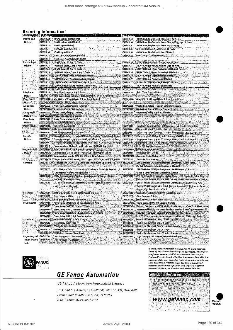
Ordering Information 0ercriptioliM Discrete Input IC693364230 -120 VAC Isolated Input t,8 Points)_ Modules
IC693MDL240 120 VAC Input (16 Points)
iC993303241 ...3,24VAC/VflOinput (16 Points)
iciasmriima 13 VDC orout Points)
VDC input, Neg/Pos Logic 18 Points)
IC993401.63 ..24 VDC input, Neg/Pos Logic (16 Po1nLel
!Discrete Output tIC693MDL310,.:,.: 13 VAC Output 0.5 rSom(1 2 Points). jj._ Middles .:1C69.9MOL.930 133240 VAC output, 2 Anip (8 Points)
.
&out o 57Anip (16 Points)...
IC693301390- 120/240 VAC Isolated Output, 2 Amp 3 Points)
icossmaiSo 24 VDC Input; Neg/Pos logic, 1 nisei Fliei:(16, Plaints).
: IC,693MDL648 348 VDC Input, NetYPoi LOgic1 rnsec filter Nett/Pos Logic 116 Points)
.1C,693MDL653' 24 VDC Input, Neg/Pos Logic, pnisec Iter (32 Points)
liIC693MDLE,54 5/12.1/0C(TTL) input, Neg/Pos,Logic, - 10693301655 24 VDC Input Neg/Pos logic: 1 ms, 132 Points)
itIC693ACC300 Simulatorpodule (8 Points)
1C33f4OL140.12/24 VDCCIumid,p.gAmp, posityoLOgic 116 POintsi
1C693MOL741 12/24 VDC Output, 05 Amp, Negative Logic 116 Points)
,,IC69311ADL742._ 32/24 VDC Output, 1 Amp, Positive (16 Points),
- iC693MDL748 48 WCOutput, 0 5 Amps, Positive Logic (8 Points) - - -
`31C693,3AD1.730E15.2243/1KOrrip-uTti,AMP:Posr7'ye Logic (8 IC693330650 -4,32j24 v0-3-C-07-tput, lie-game Loid(32 Paints) ".3-3 . -
10693M-61731 12124V06 Output, 2 Amp, Negative Logic (8 Points) IC693PA OL731 12/24 VDC Output, Positive logic 132 Points) - r..rro.4"......TR-
C63MOL732'2402/24 VDC Output, 03 Arnpt-Postwe Logic (8 Pomts).4-_,_-, ,, IC693301733 1224 VD_ Output, 05 Amp, Negat- we Logic (8 Ponds)
,,AkiC---331.40332 Zik.9/1224 VO-CTITi.)14diNeglivryWri-32PturiVt_-f- , --- ..--
;;,-,i- --- -,'-- 1C693MCIL153 12/24 VDC Output, Positive Lowe 132 Points) - I_ j 10693M131.1311 113'315itput 16,Pointsla.,,,, 1, -. _ J ., ., I _,- ,. - -.1.-_,t3 , ,` ,-.t
, _,_..;._---33.2] Relay Output IC:693301930__ Reidy Output, isokated, 4 Amp 18 Poitta) t.- - C;IC693MDLS40 Relay OutPut, lAmp (16 Points)
Module LIC693MOL93 L, Relay Outputilim17ForVitiC corithetaeWated 11172 imps ill (8 P011iSi_ > .1 t ..:.' :....., - _ '...'...1: ...."''' '',"1?.,?::;.' C Mixed Discrete - IC693MDR190 '' Mixed VO, 24 VDC Input (8 points); Relay Output (8 frolfdsk - - , 1C693MAR590 Mixed VILI, 120 VAC Input 18 Points), Relay Output 18 Perms)
Module, _ . 3, 3-3f-,371,, 3,t2'-aL,t7:7,7 4 .
Analog Input ' 1C693ALG220 Analog Input, Voltage/Ceirent, 4 Charmeli'" - - - - _ IC693AL6222 "Analog Input, Voltage 16 3mgle/8 Drfferential Channels
Modules 1169-33-941.TiliP,",:zAn7aloVinTrutiCuraireneratifuials7,.. - , ....,_ AC.icesiAtens --Toitatog In-PtiCCiiirriat,'16,Singlailannelit7-7-, . , , , . . -
V . Analog Output - IC693AL6310 ',Analog Output, Voltage, 2 Channels ' IC693AL6392 High Density Analog Output (8 Channels) -
Modules _ 13C6934.0391WAlaloT0T9tput, Clari,3 fetanoels- ,Tij" ,, .., Mixed Analog IC9939o1 G442 ; Analog Combo Module 4IN20UT
, ; Modules f7- 3v, 70-3L7.... ....Xii' '3' _ .----- --
i Moon Modules ; IC693APU300 High Speed Counter (HSC) . _ _ IC693APU305 High SpeedCeunter wilt Dray Code Encoder or an &QUAD B-Encoder Input
' -,1-6-613AP13 03.,J ;Gs- Pailituni-iioride fififi-,-1Axis,_:, ... - iisiiiiikoz : 'foigsta1 Servo in O t70-n CofoTotrer,iguussr: 7 ---.7 7 7-17: : - - - - __ ' IC693APU302 , Axis Positioning Module (APM), 2 Axis j, , . IC693DSM314 Digital Servo Motion Controller, 1-2 Axis of Digital Servo or 14 Axis Analog Servo
Specialty [IC6931TAOL59033-37oine;d33yeiedlOuiplit 31 porntsk/24 iiiii iiiispitiiArip, icsmv-e icli;ill#01tisifj'jelleiiiiii _:s i'ovier fransitu7er Module, cTiTidrr Interface 1232403VACIlm chair -
Modules 1C693PCM301 _,` Programmable Coprocessor Module, 192 KB 147 !CB Basic or C Progian), 2 Senal Pons , 1C693TCM332 - Temperature Control Module, (8) TC In and 18) 24 VDC Solid State Outputs
f ic°673P7147371:54iaTi niiite COac7ies7oitioi tie Taii KB (iia KB Basic WE Program), Pienai Pods-341-669-3-T-dfik3073 3.313Tur3-1me:raM3MConirol goMileEiteiidei ierdperikPlaiienge,iii Tc In and .3,
,... ' ' '-'" ....11'18124 VDC Solid State Outputs ° IC693PTM100 Power Transducer Module, CT and PT Interface 120240 VAC 10 5m Cable)
Communications IC693BEM331 .; _Gonna Bus Controller (Supports VO and,Datagrants),,,,_., . --,11C693P331-003,-WPTokilus DP,MasterModulej ',Lt._
Modules ` IC693CMM302 Cormnunication Module, Genus 11 Kbyte) 6CM+ (No Datagram Support) IC693PBM201 Profibtre DP Stave Module
, 1669364 33-i j CemrouThicatieds godide,6,4, link SNP, and SNI11Protocols..L -' 7,- _-- .--.3.7 3 iC6930N330 )ittindatiethdisier Module , 7
- IC693CMM321 Ethernet Interface TCP/IP Module, 10Mbs (Supports3R1P and Medium TCP/IP, Na EDDI IC693DNS201 DeviceNet Slave Module . _
Controllers `13693CPD-3-11 15-Slot Base with CPU in Base 16KBytes User Progread, Not Expandab)e - ., 41C,693CPU360 CPU 360 Module (240kEtites Configurable User Memory, 410 VO, 8 Racks), -, - -
I .,.... , - J-- 33._ .. _L. _ , ,_ j _ _ _ ..,,,,,_____14, No Built In Senal Pouts, logic Execution is 22ansecilk . ..._ _ j _ ' IC693CpU313 5 Stet Base with Turbo CPU in Base (Logic Executionrs 6 msec), 1K Registers, . , 10693CP11363 CPU 363 Module 1240KBytes Configurable User Memory 4K 1/0, 8 Racks),
(12KBytes User Program), Not Expandable . - - . ° . 2 Built In Senal Ports, Logic Execution is 22mser../K
ficbistP-70:37Tiii:siii-a6WiCf;rtio CPU Base (Logic Execution le eOksecii216bytes , - -33311-C693-OPO37364 7-33EP31364MOdele(2443Bytes Configurable User Memory 4i1/8, i Racks), No Built -In Senal Porte:
_j_,LUser,Pnigram, Not Expandable,. , -,, ' . .1`, II' :;_ _J Built In 10Mbs Ethemet.Supports_SRTP, Channels and EGO, Logic Execution is 22msecIK
Ic653CPU350 CPU 350 Module 1321(Bytes User Memoni 41( VO, 8 Racks), No Built -In Senal Ports, IC693CPU374 CPU 374 Module 1240KBytes Configurable User Memory( No Built In Senal Ports, -
Logic Execution is .22mSec/K - Built In 10/100Mbs wrth Built-tn Switch, Ethernet Supports SRTP, EGD and Channel ° '
Backplanes - Base, CPU, 10 Slots, Usewith CPU331/CSE3ii_andib;e_ _ '; IC693CHS392 Base, Expansion, 10 Slots
- ,
tIC699CHS399.,_3, lase, Remote Expansion; 10Skis-0961.), _ Power Supplies IC693PWR321 PoWer Supply, 120240 VAC, 125VDC, Standard, 30 Watts
IC693PWR322 .;Power Supply, 24/48VDE:Dianderd, 30 Watts_
IC693PWR328 Power Supply, 48 VDC, Standard, 30 Watts
11C693Pki3i1j-j POviersopoly, 120246VAO, 125VOC, Higiitapacity, 30 Watts
Cc693PWR391, , Power Supply, 24 VDC, High Capacity, 30 Watts
Accessories :699A1C303-3TRepe nniy, , ; IC693ACC302 High Capacity Battery Pack
J.31C.200AC3C003 Stir° Rash Device (for_CeU3774 only)
IC693ACC310 Filler Module, Blank - tIC693CBL300_ Rack to Rack Expansion_Cable,
Programming and IC646MPP001 Logic Developer Olt Professional
Trouble Shooting ICC46MPSDOS Logic Developer -'PLC StirWard
Tools
FANUC.
Support Logic Execution is 22m sec/k
3-3C399C-ilSi91. Base, CPU. 5iotsiedenolhCPL(331/C3331- and aho);331 1
16693CH S3911 Base, Expansion, 5 Slots
kiase,,Remot4Expansion, 5Slots (70013
1C693PWR332 Power Supply. 12 VDC, High Capacity, 30 Watts
:itiCi93A6640 SUPplyese liPS31-tddinimeter cable to comma torowerS-upptyAdapterTifieui , -
-IC693ACC341 Redundant_ Power Supply Base with 0 5 meter cable to connect to Power Supply Adapter Module
ile199/3CC3907efieduedantPower iupply Adapter (RSA) MOdrife4heTIPS-A7replices the power supply
`A-_1 on a CPU base orexpansi&bese and connects to a Redundant Power Supply Base
j'IC6936B1:30-1371rifictia IiickikPandepri7Catife,
iC693C133302 Rack to Rack Expansion Cable, 15 Meters if
10693C8612,± to Rack Expansion EabiL0-15Mrdirs.Shieided_
IC693CBL313 Recite Rack Ermanmon Cable, 8 Meters - ,
...,__LIC693CBL314 j..; _Rack to Rack Expansion Cable15 Meters, Shielded
IC646MPH101 Liigic Developer PDA Software Tool with Cable Adapter,
GE Fanuc Automation GE Fanuc Automation Information Centers
USA and the Americas 1-800-648-2001 or (434) 978-5100
Europe and Middle East (352) 727979-1
Asia Pacific 86-21-3222-9555
02003 GE Fanuc Automation Americas, Inc. All Rights Reserved. Series 90, VersaPro and LogicMaster are trademarks and Genius is a registered trademark of GE Fanuc Automation Americas, Inc.
Pro is a trademark of Profibus International. DeviceNet is a
trademark of the Open DeviceNet Vendor Association, Inc. Interbus- S is a trademark of Phoenix Contact Windows is a registered trademark of Microsoft Corporation. State Logic is a registered trademark of Adatek, Inc. Palm is a trademark of Palm, Inc.
I I I
For detailed-technical specifications- -
and product ordering Information, please, visit'the GE Fonuse-catalog at '
www.gifanuc.com_ GFA-148J
10M 06/03
Tufnell Road Yeronga SPS SP069 Backup Generator OM Manual
Q-Pulse Id TMS709 Active 29/01/2014 Page 130 of 346

GE Fanuc Automation
Programmable Control Products
Series 90-30 PLC Installation and Hardware Manual
GFK-0356Q August 2002
Tufnell Road Yeronga SPS SP069 Backup Generator OM Manual
Q-Pulse Id TMS709 Active 29/01/2014 Page 131 of 346

GFL-002
Warnings, Cautions, and Notes as Used in this Publication
Warning
Warning notices are used in this publication to emphasize that hazardous voltages, currents, temperatures, or other conditions that could cause personal injury exist in this equipment or may be associated with its use.
In situations where inattention could cause either personal injury or damage to equipment, a Warning notice is used.
Caution
Caution notices are used where equipment might be damaged if care is not taken.
Note
Notes merely call attention to information that is especially significant to understanding and operating the equipment.
This document is based on information available at the time of its publication. While efforts have been made to be accurate, the information contained herein does not purport to cover all details or variations in hardware or software, nor to provide for every possible contingency in connection with installation, operation, or maintenance. Features may be described herein which are not present in all hardware and software systems. GE Fanuc Automation assumes no obligation of notice to holders of this document with respect to changes subsequently made.
GE Fanuc Automation makes no representation or warranty, expressed, implied, or statutory with respect to, and assumes no responsibility for the accuracy, completeness, sufficiency, or usefulness of the information contained herein. No warranties of merchantability or fitness for purpose shall apply.
The following are trademarks of GE Fanuc Automation North America, Inc.
Alarm Master Field Control Modelmaster Series 90 CIMPLICITY GEnet Motion Mate Series One CIMPLICITY Control Genius PowerMotion Series Six CIMPLICITY PowerTRAC Genius PowerTRAC ProLoop Series Three CIMPLICITY 90-ADS Helpmate PROMACRO VuMaster CIMSTAR Logicmaster Series Five Workmaster
©Copyright 1998-2002 GE Fanuc Automation North America, Inc. All Rights Reserved.
Tufnell Road Yeronga SPS SP069 Backup Generator OM Manual
Q-Pulse Id TMS709 Active 29/01/2014 Page 132 of 346

RFI Standards
The Series 90-30 PLC and its associated modules have been tested and found to meet or exceed the requirements of FCC Rule, Part 15, Subpart J. The Federal Communications Commission (FCC) requires the following note to be published according to FCC guidelines.
NOTE
This equipment generates, uses, and can radiate radio frequency energy and if not installed in accordance with this instruction manual, may cause harmful interference to radio communications. It has been tested and found to comply with the limits for a Class A digital device pursuant to Part 15 of the FCC Rules, which are designed to provide reasonable protection against harmful interference when operated in a commercial environment. Operation of this equipment in a
residential area is likely to cause harmful interference, in which case the user will be required to correct the interference at his own expense.
The following note is required to be published by the Canadian Department of Communications.
NOTE
This digital apparatus does not exceed the Class A limits for radio noise emissions from digital apparatus set out in the radio interference regulations of the Canadian Department of Communications.
The following statements are required to appear in the Series 90_-30 Installation Manual and the Series 90_-30 I/O Specifications Manual for Class I Div 2 Hazardous Locations.
1. EQUIPMENT LABELED WITH REFERENCE TO CLASS I, GROUPS A, B, C, and D, DIV. 2 HAZARDOUS LOCATIONS IS SUITABLE FOR USE IN CLASS I, DIVISION 2,
GROUPS A, B, C, D OR NON-HAZARDOUS LOCATIONS ONLY.
2. WARNING - EXPLOSION HAZARD - SUBSTITUTION OF COMPONENTS MAY IMPAIR SUITABILITY FOR CLASS I, DIVISION 2:
3. WARNING - EXPLOSION HAZARD - DO NOT DISCONNECT EQUIPMENT UNLESS POWER HAS BEEN SWITCHED OFF OR THE AREA IS KNOWN TO BE NON-HAZARDOUS.
4. ALL UNUSED SLOTS IN ALL BASEPLATES MUST BE POPULATED WITH FILLER MODULES, IC693ACC310, OR EQUIVALENT.
GFK-0356Q iii
Tufnell Road Yeronga SPS SP069 Backup Generator OM Manual
Q-Pulse Id TMS709 Active 29/01/2014 Page 133 of 346

Preface
This manual describes the GE Fanuc Series 90-30 Programmable Logic Controller (PLC). It contains a description of hardware components and provides basic hardware installation procedures. The Series 90-30 PLC is a member of the Series 90_ family of Programmable Logic Controllers from GE Fanuc.
For a list of product standards, refer to data sheet GFK-0867B or later, GE Fanuc Approvals, Standards, General Specifications which lists all of the standards for GE Fanuc products. Installation instructions in this manual are provided for installations that do not require special procedures for noisy or hazardous environments. For installations that must conform to more stringent requirements (such as CE Mark), see GFK-1179, Installation Requirements for Conformance to Standards.
What's New in This Manual
Added the model 374 CPU, which supports connection to an Ethernet network through two built-in 10BaseT/100BaseTx auto-negotiating full-duplex Ethernet ports. Models 364 (release 9.10 and later) and 374 are the only Series 90-30 CPUs that support Ethernet Global Data. Note that the CPU374 is supported only by the Windows® -based programmers.
Other corrections and clarifications as necessary.
Related Publications
For more information on Series 90-30 products, refer to these publications. (For a publication to
product catalog number cross-reference refer to Appendix G):
GFK-0255 - Series 9ØTM PCM and Support Software User's Manual
GFK-0256 - MegaBasicTM Programming Reference Manual
GFK-0293 - Series 9OTM -30 High Speed Counter User's Manual
GFK-0401 - Workmaster® II PLC Programming Unit Guide to Operation
GFK-0402 - Series 9ØTM -30 and 90-20 PLC Hand-Held Programmer User's Manual
GFK-0412 - Genius® Communications Module User's Manual
GFK-0466 - Logicmaster 9OTM Series 90Th' -30/20/Micro Programming Software User's Manual
GFK-0467 - Series 90Th' -30/20/Micro Programmable Controllers Reference Manual
GFK-0487 - Series 90Th' PCM Development Software (PCOP) User's Manual
GFK-0499 - CIMPLICITY® 90-ADS Alphanumeric Display System User's Manual
GFK-0356Q
Tufnell Road Yeronga SPS SP069 Backup Generator OM Manual
Q-Pulse Id TMS709 Active 29/01/2014 Page 134 of 346

Preface
vi
GFK-0582 - Series 90Tm PLC Serial Communications User's Manual
GFK-0631 - Series 9011' -30 I/O LINK Interface User's Manual
GFK-0641 - CIMPLICITY® 90-ADS Alphanumeric Display System Reference Manual
GFK-0664 - Series 90Tm-30 PLC Axis Positioning Module Programmer's Manual
GFK-0685 - Series 90T14 Programmable Controllers Flow Computer User's Manual
GFK-0695 - Series 90'14-30 Enhanced Genius) Communications Module User's Manual
GFK-0726 - Series 90'14-30 PLC State Logic Processor User's Guide
GFK-0732 - Series 901'4-30 PLC ECLiPS User's Manual
GFK-0747 - Series 901/1-30 PLC OnTOP User's Guide
GFK-0750 - On Top for Series 90Tm-30 (State Logic) Program User's Manual
GFK-0781 - Motion MateTM APM300 for Series 90Tm-30 PLC Follower Mode User's Manual
GFK-0823 - Series 9ØTM -30 I/O LINK Master Module User's Manual
GFK-0828 - Series 90TM -30 Diagnostic System User's Manual
GFK-0840 - Motion Mater 4 APM300 for Series 901m -30 PLC Standard Mode User's Manual
GFK-0867 - GE Fanuc Product Agency Approvals, Standards, General Specifications
GFK-0898 - Series 901m -30 PLC I/O Module Specifications
GFK-1028 - Series 9ØTM -30 I/O Processor Module User's Manual
GFK-1034 - Series 9QTM -30 Genius® Bus Controller User's Manual
GFK-1037 - Series 9OTM -30 FIP Remote I/O Scanner User's Manual
GFK-1056 - Series 9011" -30 State Logic Control System User's Manual
GFK-1186 - TCP/IP Ethernet Communications for the Series 90_-30 PLC Station Manager Manual
GFK-1179 - Series 9OTM PLC Installation Requirements for Conformance to Standards
GFK-1464 - Motion Mate DSM302 for Series 90T11 -30 PLCs User's Manual
GFK-1466 - Temperature Control Module for the Series 901m-30 PLC User's Manual
GFK-1541 - TCP/IP Ethernet Communications for the Series 901m PLC User's Manual
Series 90111-30 PLC Installation and Hardware Manual - August 2002 GFK-0356Q
Tufnell Road Yeronga SPS SP069 Backup Generator OM Manual
Q-Pulse Id TMS709 Active 29/01/2014 Page 135 of 346

Contents
Chapter 1 Overview of the Series 90-30 PLC 1-1
The Basic Parts of a Series 90-30 PLC 1-1
Assembling a Basic Series 90-30 PLC System 1-2
What else would be needed to make this basic system functional? 1-6
What if the application requires more than five modules? 1-6
What if the application requires more than ten modules? 1-7
What is the Difference Between Expansion and Remote baseplates? 1-8
What if I need to cover more than 700 feet (213 meters)? 1-9
Chapter 2 Installation 2-1
Receiving your Products - Visual Inspection 2-1
Pre-installation Check 2-1
Warranty Claims 2-1
Working with Series 90-30 Modules 2-2 Module Features 2-2 Installing a Module 2-3
Removing a Module 2-4 Installing a Module's Terminal Board 2-5
Removing a Module's Terminal Board 2-6 I/O Module Terminal Board Posts 2-7
Installing and Removing Terminal Boards with Holding Screws 2-7
Baseplate Mounting 2-8
Mounting a Baseplate to a Panel 2-8
Mounting a Baseplate to a 19" Rack 2-8
Grounding Procedures 2-11
System Grounding Procedures 2-11
Ground Conductors 2-11
Series 90-30 PLC Equipment Grounding 2-12 Baseplate Safety Grounding 2-12 Grounding 19" Rack-Mounted Baseplates 2-13 Programmer Grounding 2-13
Module Shield Grounding 2-14 Shield Grounding Information for CPUs with External Port Connections 2-14 CPU351 and 352 Shield Grounding 2-14 CPU363, CPU364, and CPU374 Shield Grounding 2-16 Additional Modules with Shield Grounding Requirements 2-16
General Wiring Guidelines 2-17
Discrete I/O Module Connection Methods 2-18
Connections to I/O Module Terminal Boards 2-18
Terminal Block Quick Connect Installation for 16-Point Discrete Modules 2-19
Installation of 32-Point Discrete, 50-Pin Connector Modules 2-19 Using Weidmuller #912263 Terminal Block 2-19 Using a Generic Terminal Block or Strip 2-20 Direct Method 2-20
Installation of Discrete 32-Point, Dual 24-Pin Connector Modules 2-20 Using a TBQC 2-20
GFK-0356Q vii
Tufnell Road Yeronga SPS SP069 Backup Generator OM Manual
Q-Pulse Id TMS709 Active 29/01/2014 Page 136 of 346
Contents
Chapter 3
With a Generic Terminal Block/Strip 2-20 Direct Method 2-21
General Wiring Methods for Analog Modules 2-21
Analog Input Module Wiring Methods 2-21 Using a Generic Terminal Block or Strip 2-21 Direct Method 2-21 TBQC not Recommended for Analog Modules 2-22
Analog Output Module Wiring 2-22 General 2-22 Using a Generic Terminal Block or Strip 2-22 Direct Method 2-22 TBQC not Recommended for Analog Modules 2-22
AC Power Source Connections 2-23 AC Input Wiring to AC/DC Power Supplies 2-23 Power Supply Overvoltage Protection Devices 2-24
Special Installation Instructions for Floating Neutral (IT) Systems 2-25 Definition of Floating Neutral Systems 2-25
Use These Special Installation Instructions for Floating Neutral Systems 2-26 DC Power Source Connections 2-27
DC Input Wiring to AC/DC and DC-Only Power Supplies 2-27 +24 VDC Output (All Supplies) 2-27
Basic Installation Procedure 2-28
Baseplates 3-1
Baseplate Types 3-1
Common Baseplate Features 3-1
Two Baseplate Sizes 3-2
Baseplate Terms 3-3
CPU Baseplates 3-4 Embedded CPU Baseplates (Figures 3-2 and 3-3) 3-4 Modular CPU Baseplates (Figures 3-4 and 3-5) 3-6 Expansion Baseplates (Figures 3-6 and 3-7) 3-7 Remote Baseplates (Figures 3-8 and 3-9) 3-8 I/O Bus Expansion Cables 3-10 Differences Between Remote and Expansion Racks 3-11
Mixing Expansion and Remote Baseplates in a System 3-11 Termination Requirement for Expansion or Remote System 3-12 Powering Down Individual Expansion or Remote Baseplates 3-12 Series 90-30 PLC Backplane 3-12 Rack Number DIP Switch on Expansion and Remote Baseplates 3-13 Expansion and Remote Baseplates Connection Example 3-15 Baseplate Mounting Dimensions 3-16
Embedded CPU (311, 313, and 323) Baseplate Dimensions 3-16 Modular CPU, Expansion, and Remote Baseplate Dimensions 3-18
viii Series 90114-30 PLC Installation and Hardware Manual - August 2002 GFK-0356Q
Tufnell Road Yeronga SPS SP069 Backup Generator OM Manual
Q-Pulse Id TMS709 Active 29/01/2014 Page 137 of 346

Contents
Load Ratings, Temperature, and Mounting Position 3-19
Baseplate Adapter Brackets for 19" Rack Mounting 3-20
Baseplate Comparison Table 3-22
Chapter 4 Power Supplies 4-1
Power Supply Categories 4-1
Power Supply Feature Comparison 4-1
AC/DC Input Power Supplies 4-2
IC693PWR321 Standard Power Supply, 120/240 VAC or 125 VDC Input 4-2
IC693PWR330 High Capacity Power Supply, 120/240 VAC/125 VDC Input 4-4
Field Wiring Connections for the AC/DC Input Power Supplies 4-5
Isolated 24 VDC Supply Output Connections 4-6
DC Input Only Power Supplies 4-7
IC693PWR322 Standard Power Supply, 24/48 VDC Input 4-7
Calculating Input Power Requirements for IC693PWR322 4-8
IC693PWR328 Standard Power Supply, 48 VDC Input 4-10
Calculating Input Power Requirements for IC693PWR328 4 -11
Input Power/Current Calculation for IC693PWR328 Power Supply 4-12
IC693PWR331 High Capacity Power Supply, 24 VDC Input 4-13
Current Derating for Higher Temperatures 4-14 Calculating Input Power Requirements for IC693PWR331 4-15
Field Wiring Connections to the DC Input-Only Power Supplies 4-15
Common Series 90-30 Power Supply Features 4-16
Status Indicator Lights on all Power Supplies 4-16
Input Overvoltage Protection Devices 4-16
Output Voltage Connections to Backplane (All Supplies) 4-17
Overcurrent Protection (all Supplies) 4-18
Timing Diagram 4-18
CPU Serial Port Connector on Power Supply (All Supplies) 4-19
CPU Serial Port Information 4-19
Backup Battery for RAM Memory (All Supplies) 4-20
Chapter 5 CPUs 5-1
CPU Types for Series 90-30 PLCs 5-1
Embedded CPUs 5-1
Modular CPUs 5-2
General CPU Features 5-3 Microprocessor 5-3 CPU Serial Port (Connector on Power Supply) 5-3 Memory Volatility 5-4 RAM Memory 5-5 RAM Memory Backup/Backup Battery Information 5-5 Programmable Read-Only Memory (PROM) Types 5-5 Uses of PROM devices in the 90-30 CPUs 5-5
GFK-0356Q Contents ix
Tufnell Road Yeronga SPS SP069 Backup Generator OM Manual
Q-Pulse Id TMS709 Active 29/01/2014 Page 138 of 346

Contents
CPU Firmware 5-6 Determining CPU Revision Levels (Versions) 5-7
EPROM and EEPROM User Program Storage Options 5-8
Comparing EPROM and EEPROM Features 5-8
Procedure for Creating an EPROM 5-9
Flash Memory 5-9
Series 90-30 CPU Capacities 5-10 User Memory Addresses (References) 5-10 Difference Between a Memory Address and a Nickname 5-10 User Memory Reference Types 5-11
Application Program Compatibility 5-12 CPU Time-of-Day (TOD) Clock Accuracy 5-12 Breakfree SNP Protocol 5-13
350-374 CPUs 5-13 Compatibility With Hand-Held Programmer (HHP) and Memory Card 5-13 350-374 CPU Advanced Features 5-14 Details of 350 - 374 CPU Advanced Features 5-14
Hardware Features of the 350-364 CPUs 5-18
CPU350 and CPU360 Hardware Features 5-18 CPU Firmware Upgrade 5-18
CPU351, CPU352, and CPU363 Hardware Features 5-19 CPU Firmware Upgrade 5-19 Keyswitch 5-19 Shield Ground Connection Tab 5-20 Serial Ports 5-20 Serial Port Front Panel Connectors 5-20 Serial Port Status LEDs 5-20 Protocols Supported 5-21 Pin Assignments for CPU351, CPU352, and CPU363 Serial Ports 1 & 2 5-22
CPU364 Hardware Features 5-23 LED Indicators 5-23 Ethernet Restart Pushbutton 5-23 Keyswitch 5-24 Front Panel Connectors 5-24 Shield Ground Connection Tab 5-24 Firmware Upgrade 5-24
CPU374 Hardware Features 5-25 LED Indicators 5-25 Ethernet Restart Pushbutton 5-25 Keyswitch 5-26 Front Panel Connectors 5-26 Shield Ground Connection Tab 5-26 Firmware Upgrade 5-26
CPU Data Sheets 5-27 CPU311 Catalog Number IC693CPU311 5-28 CPU313 Catalog Number IC693CPU313 5-29 CPU323 Catalog Number IC693CPU323 5-30 CPU331 Catalog Number IC693CPU331 5-31
x Series 90Th-30 PLC Installation and Hardware Manual - August 2002 GFK-0356Q
Tufnell Road Yeronga SPS SP069 Backup Generator OM Manual
Q-Pulse Id TMS709 Active 29/01/2014 Page 139 of 346

Contents
CPU340 Catalog Number IC693CPU340 5-32 CPU341 Catalog Number IC693CPU341 5-33 CPU350 Catalog Number IC693CPU350 5-34 CPU351 Catalog Number IC693CPU351 5-35
CPU352 Catalog Number IC693CPU352 5-36 CPU360 Catalog Number IC693CPU360 5-37
CPU363 Catalog Number IC693CPU363 5-38
CPU364 Catalog Number IC693CPU364 5-39
CPU374 Catalog Number IC693CPU374 5-40
Chapter 6 Memory Backup/Battery Backup 6-1
Backup Battery for RAM Memory (All Supplies) 6-1
Battery Replacement Instructions 6-2
Battery Replacement/Memory Protection Factors 6-3
The Importance of Backing up Your Program 6-3
Factors Affecting Battery Life 6-4
Low Battery Warning Methods 6-4
Operating Without a Memory Backup Battery 6-6 RAM Memory Battery Backup Connection Path 6-8
Super Capacitor Memory Backup 6-8
Maintaining RAM Memory During Storage or Shipment of a CPU 6-9 Modular CPUs 6-9 Embedded CPUs 6-9 Battery Accessory Kit (IC693ACC315) 6-9 Battery Accessory Kit Installation 6-10
External Battery Module (IC693ACC302) 6-10 Batteries in Power Supplies on Expansion or Remote Racks 6-11
Chapter 7 Input/Output Modules 7-1
Basic I/O Module Types 7-1
Discrete I/0 Modules 7-2
Discrete I/0 Module Point Density 7-2
Standard Density Discrete I/0 Module Features 7-2
Wiring Standard Density (16-Point or Less) Discrete Modules 7-4
Discrete Relay Output Module Protection 7-4 High Density (32-Point) Discrete Module Features 7-4
Wiring Methods for 32-Point Discrete I/O Modules 7-6 Modules with Single 50-Pin Connector 7-6 Modules with Dual 24-Pin Connectors 7-7
Analog Module Features 7-8
Wiring Methods for Analog Modules 7-9 Analog Input Module Wiring Methods 7-9 Analog Output Module Wiring 7-10
I/O Module Power Supply Current Draw 7-10
GFK-0356Q Contents xi
Tufnell Road Yeronga SPS SP069 Backup Generator OM Manual
Q-Pulse Id TMS709 Active 29/01/2014 Page 140 of 346

Contents
Chapter 8
I/0 Module Wire Routing 7-11
Grouping Modules to Keep Wires Segregated 7-11
IC693DVM300 Digital Valve Driver Module 7-12 Indicator LEDs 7-12 DVM Specifications 7-13
Fuses 7-13
Option Modules 8-1
Third-Party Option Modules and the Accompany Program 8-1
Option Modules Discussed in this Chapter 8-1
IC693CMM301 Genius Communications Module (GCM) 8-2
Status LEDs 8-3
GCM Documentation 8-3
IC693CMM302 Enhanced Genius Communications Module (GCM+) 8-4
Status LEDs 8-5
GCM+ Documentation 8-5
IC693BEM331 Genius Bus Controller (GBC) 8-6
Number of Genius Bus Controllers 8-7
Status LEDs 8-7
Compatibility 8-7 Series 90-30 PLC 8-7 Series Six PLC 8-7 Genius Hand-Held Monitor 8-8 Hand-Held Programmer 8-8 Genius I/O Blocks 8-8 Genius Bus 8-8
Diagnostics 8-8
Datagrams 8-9
Global Data 8-9 Sending Global Data 8-9 Receiving Global Data 8-9 Genius Bus Controller Documentation 8-9
IC693BEM340 FIP Bus Controller (FBC) Module 8-10 Status LEDs 8-11
Serial Port 8-11
FIP Bus Connectors 8-11
IC693BEM330 FIP Remote I/O Scanner Module 8-12 Features of the Remote I/0 Scanner 8-12 FIP Bus Interface 8-13 Module Description 8-13 Connectors 8-14 LEDs 8-14 FIP Remote I/O Scanner Documentation: 8-14
IC693APU301/302 Motion Mate Axis Positioning Module (APM) 8-15
xii Series 90Tm-30 PLC Installation and Hardware Manual -August 2002 GFK-0356Q
Tufnell Road Yeronga SPS SP069 Backup Generator OM Manual
Q-Pulse Id TMS709 Active 29/01/2014 Page 141 of 346

Contents
APM Cables 8-16
Motion Mate APM Module Documentation 8-16
IC693DSM302 Motion Mate Digital Servo Module (DSM302) 8-17
Features. 8-18
IC693DSM302 Documentation 8-18
IC693DSM314 Motion Mate Digital Servo Module (DSM314) 8-20 Features 8-21 IC693DSM314 Documentation 8-22
IC693APU300 High Speed Counter (HSC) Module 8-23
IC693BEM320 I/O LINK Interface (Slave) Module 8-24
IC693BEM321 I/O LINK Master Module 8-25 Compatibility 8-26
IC693APU305 I/O Processor Module 8-27 Module Features 8-28
IC693CMM321 Ethernet Interface Module 8-29
IC693PCM300/301/311 Programmable Coprocessor Module (PCM) 8-31
IC693CMM311 Communications Coprocessor Module (CM_M) 8-34
IC693ADC311 Alphanumeric Display Coprocessor (ADC) 8-35
IC693TCM302/303 Temperature Control Modules (TCM) 8-37 Connections 8-37 LED Indicators 8-38 Internal Fuse 8-38 Automatic Data Transfers Between TCM and PLC 8-38 Comparison of TCM302 and TCM303 Modules 8-39
IC693PTM100/101 Power Transducer (PTM) 8-40 Difference Between PTM100 and PTM101 8-40 Capabilities 8-40
Operating Modes 8-40 Automatic Data Transfers Between PTMPM and PLC 8-41
Compatibility 8-41
Dimensions 8-42
PTMPM Indicator LEDs 8-42
General Mounting Information 8-42
Baseplate Type and Allowable Number of PTMPM Modules 8-43
Power Supply Requirement 8-43
Memory Requirement 8-43
Configuration 8-43
Ordering Information 8-43 Documentation 8-43
Chapter 9 State Logic Products 9-1
State Logic Overview 9-1
State Logic Products 9-1
Baseplates and Power Supply, I/O, and Option Modules 9-1
GFK-0356Q Contents xiii
Tufnell Road Yeronga SPS SP069 Backup Generator OM Manual
Q-Pulse Id TMS709 Active 29/01/2014 Page 142 of 346

Contents
Chapter 10
AD693CMM301 State Logic Serial Communications Module (SCM) 9-2
Description 9-2 OK LED 9-2 Reset Button 9-2 Serial Connector 9-3
Cable Information 9-3
State Logic SCM Documentation 9-3
IC693SLP300 State Logic Processor Module 9-4
Description 9-4
SLP Features 9-5
Memory 9-5
Installation 9-5
Status Light 9-6
Pushbutton 9-6
Battery 9-7
Cable Information 9-7
Hardware Specifications 9-7
State Logic Processor (SLP) Documentation 9-7
State Logic CPUs 9-8
Features of State Logic CPUs 9-8
Model CSE311, CSE313 and CSE323 Embedded CPU Baseplates 9-9
Model CSE331 and CSE340 Modular CPUs 9-10
CPU Serial Port Connector on Power Supply 9-11
Configuring the State Logic CPUs 9-11
State Logic CPU Firmware and PROM Configurations 9-13
State Logic CPU Data Sheets 9-13
CSE311 Catalog Number IC693CSE311 9-14 CSE313 Catalog Number IC693 CSE313 9-15
CSE323 Catalog Number IC693CSE323 9-16 CSE331 Catalog Number IC693CSE331 9-17
CSE340 Catalog Number IC693CSE340 9-18
Cables 10-1
Cable Data Sheets 10-7
IC647CBL704 Workstation Interface to Series 90 CPU (SNP Port) Cable 10-8 Function of cable 10 -8
IC690CBL701 PCM, ADC, CMM to Workmaster (PC-XT) Cable 10-12 Function of cable 10-12 Cable Specifications 10-12 Wiring Diagram 10-12
PCM to Programmer Cable Installation 10-13
IC690CBL702 PC-AT to PCM, ADC, CMM Cable 10-14 Function of cable 10-14 Cable Specifications 10-14
xiv Series 90114-30 PLC Installation and Hardware Manual - August 2002 GFK-0356Q
Tufnell Road Yeronga SPS SP069 Backup Generator OM Manual
Q-Pulse Id TMS709 Active 29/01/2014 Page 143 of 346

Contents
Wiring Diagram 10-14
PCM to Programmer Cable Installation 10-15
IC690CBL705 Worlunaster II (PS/2) to PCM, ADC, CMM Cable 10-16 Function of cable 10-16 Cable Specifications 10-16 Wiring Diagram 10-16
PCM to Programmer Cable Installation 10-17
IC690CBL714A Multidrop Cable 10-18 Purpose 10-18 Specifications 10-18 IC690CBL714A Multi-Drop Cable Wiring Diagram 10-19
Connection Diagrams for IC690CBL714A Cable 10-20
IC693CBL300/301/302/312/313/314 I/0 Bus Expansion Cables 10-22 Description 10-22 Cable Lengths 10-22 Function of Cables 10-22 Connecting the Cables 10-23 Important Notes About I/O Bus Expansion Cables 10-23 Cable Application Suggestions 10-23 Using Standard Cables 10-23 Using Custom Built cables 10-24
Building Custom Length I/0 Bus Expansion Cables 10-24 Two Types of Custom Built Cables 10-24 Components Needed to Build Custom Length I/O Bus Expansion Cables 10-24 Expansion Port Pin Assignments 10-25 I/O Expansion Bus Termination 10-25 Shield Treatment 10-26 Alert for Users of Early Remote Baseplate Versions 10-26 Making a 100% Shielded Cable 10-27 Wiring Diagrams 10-28 Application Examples 10-31
Expansion System Cable Connections 10-31 Remote and Expansion System Cable Connection Example 10-31
IC693CBL303 Hand-Hand Programmer and Converter (IC690ACC900) Cable 10-33
Function of cable 10-33
Cable Specifications 10-33
Wiring Diagram 10-34
Connecting the Cable 10-34
IC693CBL304/305 Port Expansion (WYE) Cables for PCM, ADC, and CMM 10-35
Function of cable 10-35
Cable Specifications 10-35
Wiring Information 10-36
IC693CBL306/307 Extension Cables (50-Pin) for 32 Point Modules 10-38
Function of cable 10-38
Cable Specifications 10-38
IC693CBL308/309 I/O Cables (50-Pin) for 32 Point Modules 10-40
Specifications 10-40
Wiring Information 10-40
GFK-0356Q Contents xv
Tufnell Road Yeronga SPS SP069 Backup Generator OM Manual
Q-Pulse Id TMS709 Active 29/01/2014 Page 144 of 346

Contents
Chapter 11
IC693CBL310 I/O Interface Cable (24-Pin) for 32 Point Modules 10-42
Function of cable 10-42 Replacement/Obsolescence Information 10-43
Connector Depth for Cable 1C693CBL310 10-43
IC693CBL311/317/319/320 I/0 Interface Cables for Power Mate APM Modules 10-45
Function of cable 10-45
Specifications 10-45
Wiring Information 10-46
IC693CBL315 I/O Interface Cable (24-Pin) for 32 Point Modules 10-49 Function of cable 10-49 Building Custom Length Cables for 24-Pin Connectors 10-49
Replacement/Obsolescence Information 10-51 Connector Depth for 1C693CBL315 10-51
IC693CBL316 Serial Cable, 9-Pin D-Shell to RJ-11 Connector 10-53
Description 10-53
Typical Applications 10-53
IC693CBL321/322/323 I/O Faceplate Connector to Terminal Block Connector, 24-Pin10-54 Function of cable 10-54 Cable Specifications 10-54
Connector Depth 10-55
IC693CBL327/328 I/0 Interface Cables with Right Angle 24-Pin Connector 10-57 Description 10-57 Applications 10-57 Specifications 10-58
Connector Depth for Cables 1C693CBL327/328 10-58
Building Custom Length 24-pin Connector Cables 10-59 Connector Depth for Custom Built Cables 10-60
Possible Uses for These Cables (Factory or Custom Built) 10-61
IC693CBL329/330/331/332/333/334 Cables 24-Pin I/0 Faceplate Connector to Terminal Block Connector 10-62
Description 10-62 Connector Depth 10-63
Applications 10-64 IC693CBL340/341 PTM Interface Cables 10-65
Documentation 10-67
Programmer Hardware Products 11-1
Products Discussed in this Chapter 11-1
IC640WMI310/320 Work Station Interface Boards 11-2 Replacing Workmaster Computers 11-3
IC690ACC900 RS-422/RS-485 to RS-232 Converter 11-3
IC690ACC901 Miniconverter Kit 11-4 IC693PRG300 Hand-Held Programmer (HHP) 11-5
HHP Features 11-6
xvi Series 90n-30 PLC Installation and Hardware Manual - August 2002 GFK-0356Q
Tufnell Road Yeronga SPS SP069 Backup Generator OM Manual
Q-Pulse Id TMS709 Active 29/01/2014 Page 145 of 346
Contents
HHP Memory Card (IC693ACC303) 11-6 HHP Modes of Operation 11-6 Documentation 11-6
IC693PIF301/400 Personal Computer Interface (PCIF) Cards 11-7
IC655CCM590 Isolated Repeater/Converter 11-8
IC690ACC903 Port Isolator 11-8
Chapter 12 System Design 12-1
Introduction 12-1
Step 1: Planning Your System 12-1
Step 2: Determining I/O Requirements 12-1 Additional I/O Module Selection Factors 12-2
Step 3: Selecting Option Modules 12-2
Step 4: Selecting a CPU 12-4
Step 5: Selecting Baseplates 12-5
Step 6: Selecting Power Supplies 12-6
Reducing PLC Module Count by Using Other GE Fanuc Products 12-7
Designing For Safety 12-8
Protection From Electrical Shock 12-8
Fire Prevention 12-8
Protection From Mechanical Hazards 12-8
Protection From Electrical Failure 12-8 Protection From Design Changes or Overrides 12-9 Safety Documentation 12-10 Guarding Against Unauthorized Operation 12-10 Labeling, Guarding, and Lighting Issues 12-10 Equipment Accessibility Issues 12-10
Number of Modules Per Series 90-30 PLC System 12-11
Calculating Power Supply Loading 12-12
Load Requirements for Hardware Components 12-12 Power Supply Loading Calculation Examples 12-14
Scan (Sweep) Time Calculation 12-15
Major Design Factors Affecting Scan Time 12-16
Where to Find Scan Time Information 12-16
Calculating PLC Heat Dissipation 12-17
System Layout Guidelines 12-17
Benefits of a Good Layout - Safe, Reliable, and Accessible 12-17
PLC Rack Location and Clearance Requirement 12-17
Location of Modules in the PLC Racks 12-18
Allowable Module Locations 12-19
Series 90-30 PLC Layout Example 12-20
PLC Mounting Position 12-21
Recommended Upright Mounting Orientation 12-21
Derated Horizontal Mounting Orientation 12-21
IIIGFK-0356Q Contents xvii
Tufnell Road Yeronga SPS SP069 Backup Generator OM Manual
Q-Pulse Id TMS709 Active 29/01/2014 Page 146 of 346

Contents
Chapter 13
Appendix A
Appendix B
Maintenance and Troubleshooting 13-1
Troubleshooting Features of Series 90-30 Hardware 13-1
Indicator Lights (LEDs) and Terminal Board 13-1
Module LED Indicators 13-2
Troubleshooting Features of Programming Software 13-3
Ladder Screens 13-3
Configuration Screens 13-3
Fault Tables 13-3
System Status References 13-3
Reference Tables 13-4
Override feature 13-4
Sequential Event Recorder (SER), DOI° functional instruction 13-4
Replacing Modules 13-5
Series 90-30 Product Repair 13-5
Module Fuse List 13-6
Spare/Replacement Parts 13-7
Preventive Maintenance Suggestions 13-8
Getting Additional Help and Information 13-9
Serial Ports and Cables A-1
RS-422 Interface A-1
Cable and Connector Specifications A-2 Series 90 PLC Serial Port A-3
Workmaster Serial Port A-4 RS-232/RS-485 Converter A-7
IC690ACC901 Miniconverter Kit A-7 IC690ACC900 Obsolete Converter A-7
Serial Cable Diagrams A-8 RS-232 Point-to-Point Connections A-8 RS-422 Point-to-Point Connection A-10 Multidrop Connections A-10
IC690ACC900 Converter B-1
Features B-1
Functions B-1
Location in System B-2 Installation B-2 Cable Description B-3
RS-232 Interface Pin Assignments B-4 RS-422/RS-485 Interface Pin Assignments B-5
Logic Diagram B-6 Jumper Configuration B-7
xviii Series 90"-30 PLC Installation and Hardware Manual - August 2002 GFK-0356Q
Tufnell Road Yeronga SPS SP069 Backup Generator OM Manual
Q-Pulse Id TMS709 Active 29/01/2014 Page 147 of 346

Contents
Example of Cable Configurations B-9
Appendix C IC655CCM690 Isolated Repeater/Converter C-1
Description of the Isolated Repeater/Converter C-1
Logic Diagram of the Isolated Repeater/Converter C-3
Pin Assignments for the Isolated Repeater/Converter C-4
System Configurations C-5
Simple Multidrop Configuration C-6
Complex Multidrop Configuration C-6
Rules for Using Repeater/Converters in Complex Networks C-7
Cable Diagrams C-8
Appendix D IC690ACC901 Miniconverter Kit D-1
Description of Miniconverter D-1
Pin Assignments D-2
Pin Assignments, RS-232 Port D-2
Pin Assignments, RS-422 Port D-2
System Configurations D-3
Cable Diagrams (Point-To-Point) D-3
Appendix E IC690ACC903 Port Isolator E-1
Connectors E-2
Logic Diagram E-3
Installation E-4
Specifications E-7
Appendix F Calculating Series 90-30 Heat Dissipation F-1
Overview F-1
Information Required F-1
Procedure F-2
Step 1: Basic Method to Calculate Module Dissipation F-2
Step 2: Calculation for PLC Power Supplies F-3
Step 3: Output Calculations for Discrete Output Modules F-3
Step 4: Input Calculations for Discrete Input Modules F-4
Step 5: Final Calculation F-6
Other Information Related to Enclosure Sizing F-6
Appendix G Catalog Number to Publication Cross-Reference G-1
General System Information G-2
Analog I/O Modules G-2
Baseplates G-2
Communications Modules G-3
GFK-0356Q Contents xix
Tufnell Road Yeronga SPS SP069 Backup Generator OM Manual
Q-Pulse Id TMS709 Active 29/01/2014 Page 148 of 346

Contents
CPU Modules, CPU311-CPU341 G-3
CPU Modules, CPU350 - CPU374 G-4 Digital Valve Driver Module G-5
Discrete I/O Modules G-5
Genius Modules G-6 Motion Modules G-6 Other Option Modules G-6 Power Supply Modules G-7
Programming Device G-7 State Logic Products G-7
Publication Revision Letters G-8
Other Sources of Information G-8
Appendix H Terminal Block Quick Connect Components H-1
Terminal Block Quick Connect Components for 16-Point Modules H-2 Terminal Blocks H-2
Cable Current Rating H-2 Cable Selection and Cross-Reference H-3 I/0 Face Plate for 16-Point Modules H-3
I/0 Face Plate Installation H-3 Module Wiring Information H-4 Cable Information H-4
Connector Pin Orientation and Connection to Module Terminal H-5 Terminal Block Information H-5
IC693ACC329 TBQC Terminal Block H-6 IC693ACC330 TBQC Terminal Block H-7 IC693ACC331 TBQC Terminal Block H-8 IC693ACC332 TBQC Terminal Block H-9 IC693ACC333 TBQC Terminal Block H-10
Terminal Block Quick Connect Components for 32-Point Modules H-11
Terminal Block H-12 Cable Selection and Cross-Reference H-12 Cable Current Rating H-12 Cable Data H-13 Terminal Block Data H-13
IC693ACC337 TBQC Terminal Block H-13
Appendix I SNP Multidrop
SNP Multidrop Overview I-1
Multidrop Cables 1-2
Limitations 1-2
Cable and Connector Specifications 1-2
MultiDrop Cable Wiring Diagram 1-3
xx Series 90114-30 PLC Installation and Hardware Manual - August 2002 GFK-0356Q
Tufnell Road Yeronga SPS SP069 Backup Generator OM Manual
Q-Pulse Id TMS709 Active 29/01/2014 Page 149 of 346
Contents
SNP Multidrop Examples 1-4
Configuring and Connecting a Programmer to a Multidrop Network 1-5
Assigning a PLC SNP ID to a PLC with Logicmaster 1-6
Connecting your Logicmaster Programmer to a PLC on a Multidrop System 1-6
SNP Multidrop Troubleshooting 1-7
Appendix J Ethernet Transceivers J-1
IC649AEA102 Ethernet 10BASE-T Transceiver J-1
Power Requirement J-1
LED Indicator Lights J-1
IC649AEA103 Ethernet 10BASE2 Transceiver J-2
Power Requirement J-2
LED Indicator Light J-2
Appendix K Tables and Formulas K-1
AWG to Metric Wire Size Conversion K-2 Temperature Conversion K-3
Formulas K-3
Conversion Information K-4 English and Metric Equivalents K-5
Appendix L 44A420084-001 EMI Line Filter L-1
44A720084-001 Optional EMI Line Filter L-1
44A720084-001 Line Filter Mounting Dimensions L-3
GFK-0356Q Contents xxi
Tufnell Road Yeronga SPS SP069 Backup Generator OM Manual
Q-Pulse Id TMS709 Active 29/01/2014 Page 150 of 346
Contents
Figure 1-1. Five-Slot CPU Baseplate 1-3
Figure 1-2. Power Supply Module 1-3
Figure 1-3. CPU Module 1-4
Figure 1-4. I/O Module 1-4
Figure 1-5. Assembling the System 1-5
Figure 1-6. A Basic System 1-6
Figure 1-7. Ten-Slot Rack 1-6
Figure 1-8. I/O Bus Expansion Cable 1-7
Figure 1-9. Connecting Expansion and Remote Baseplates 1-8
Figure 1-10. Connecting PLCs Using GBC or CMM Modules 1-9
Figure 2-1. Features of Series 90-30 Module 2-2
Figure 2-2. Installing a Module 2-3
Figure 2-3. Removing a Module 2-4
Figure 2-4. Installing an I/O Module's Terminal Board 2-5
Figure 2-5. Removing a Module's Terminal Board 2-6
Figure 2-6. Terminal Board with Holding Screws 2-7
Figure 2-7. IC693ACC308 Front Mount Adapter Bracket Installation 2-9
Figure 2-8. Dimensions for 19-inch Rack Mounting Using IC693ACC308 Adapter Bracket 2-9
Figure 2-9. IC693ACC313 Recessed Mount Adapter Bracket 2-10
Figure 2-10. Recommended System Grounding 2-11
Figure 2-11. Baseplate Grounding 2-12
Figure 2-12. CPU 351 or 352 - Attaching Shield Ground Wire 2-14
Figure 2-13. CPU 351 or 352 - Mounting the Shield Grounding Bracket and Wire 2-15
Figure 2-14. CPU 363, CPU364, or CPU374 - Attaching Ground Wire 2-16
Figure 2-15. Power Supply Terminal Boards 2-24
Figure 2-16. Overvoltage Protection Devices and Jumper Strap 2-24
Figure 3-1. Common Baseplate Features 3-2
Figure 3-2. Models IC693CPU311 and IC693CPU313 (5-Slot) Embedded CPU Baseplates 3-5
Figure 3-3. Model IC693CPU323 (10-slot) Embedded CPU Baseplate 3-5
Figure 3-4. IC693CHS397 5-Slot Modular CPU Baseplate 3-6
Figure 3-5. IC693CHS391 10-Slot Modular CPU Baseplate 3-6
Figure 3-6. IC693CHS398 5-Slot Expansion Baseplate 3-7
Figure 3-7. IC693CHS392 10-Slot Expansion Baseplate 3-8
Figure 3-8. IC693CHS399 5-Slot Remote Baseplate 3-9
Figure 3-9. IC693CHS393 10-Slot Remote Baseplate 3-9
Figure 3-10. I/0 Bus Expansion Cables 3-10
xxii Series 90nt-30 PLC Installation and Hardware Manual - August 2002 GFK-0356Q
Tufnell Road Yeronga SPS SP069 Backup Generator OM Manual
Q-Pulse Id TMS709 Active 29/01/2014 Page 151 of 346

Contents
Figure 3-11. Rack Number Selection Switch (Shown with Rack 2 Selected) 3-13
Figure 3-12. Example of Connecting Expansion Baseplates 3-14
Figure 3-13. Example of Connecting Expansion and Remote Baseplates 3-15
Figure 3-14. Model 311 and 313 5-Slot Baseplate Dimensions and Spacing Requirements 3-16
Figure 3-15. Model 323 10-Slot Baseplate Dimensions and Spacing Requirements 3-17
Figure 3-16. Modular CPU, Expansion, and Remote 5-Slot Baseplate Dimensions and Spacing Requirements 3-18
Figure 3-17. Modular CPU, Expansion, and Remote 10-Slot Baseplate Dimensions and Spacing Requirements 3-18
Figure 3-18. IC693ACC308 Front Mount Adapter Bracket Installation 3-20
Figure 3-19. Dimensions for 19" Rack Mounting Using IC693ACC308 Adapter Bracket 3-21
Figure 3-20. IC693ACC313 Recessed Mount Adapter Bracket 3-21
Figure 4-1. Standard AC/DC Input Power Supply - IC693PWR321 4-2
Figure 4-2. High Capacity AC/DC Input Power Supply - IC693PWR330 4-4
Figure 4-3. Overvoltage Protection Devices and Jumper Strap 4-6
Figure 4-4. Series 90-30 24/48 VDC Input Power Supply - IC693PWR322 4-7
Figure 4-5. Typical Efficiency Curve for 24/48 VDC Power Supply 4-8
Figure 4-6. Series 90-30 48 VDC Input Power Supply - IC693PWR328 4-10
Figure 4-7. Typical Efficiency Curve for IC693PWR328 Power Supply 4-11
Figure 4-8. Series 90-30 24 VDC Input High Capacity Power Supply - IC693PWR331 4-13
Figure 4-9. 5 VDC Current Output Derating for Temperatures above 50°C (122°F) 4-14
Figure 4-10. Overvoltage Protection Devices and Jumper Strap 4-17
Figure 4-11. Interconnection of Power Supplies 4-17
Figure 4-12. Timing Diagram for all Series 90-30 Power Supplies 4-18
Figure 4-13. Serial Port Connector 4-19
Figure 4-14. Backup Battery for RAM Memory 4-20
Figure 5-1. Models 311 and 313 (5-Slot) Embedded CPU Baseplates 5-2
Figure 5-2. IC693CHS397 5-Slot Modular CPU Baseplate 5-3
Figure 5-3. CPU Serial Port Connector on Power Supply 5-4
Figure 5-4. CPUs 351, 352, and 363 5-19
Figure 6-1. Backup Battery for RAM Memory 6-1
Figure 6-2. Installing the Battery Accessory Kit 6-10
Figure 7-1. Example of Series 90-30 Standard Density Discrete Output Module 7-3
Figure 7-2. Example of 32-Point I/O Module (IC693MDL654) With Dual Connectors 7-5
Figure 7-3. Example of 32-Point I/O Module (IC693MDL653) With Single Connector 7-5
Figure 7-4. 50-PIN, 32 Point I/O Module Connection Method 7-6
Figure 7-5. Example of Series 90-30 Analog Current Output Module 7-9
Figure 7-6. IC693DVM300 Digital Valve Driver Module 7-12
GFK-0356Q Contents _trill
Tufnell Road Yeronga SPS SP069 Backup Generator OM Manual
Q-Pulse Id TMS709 Active 29/01/2014 Page 152 of 346

Contents
Figure 8-1. The IC693CMM301 GCM Module 8-2
Figure 8-2. Genius Bus Wiring Schematic 8-3
Figure 8-3. Example of Genius Communications Network 8-3
Figure 8-4. Enhanced Genius Communications Module 8-4
Figure 8-5. Genius Bus Controller Module 8-6
Figure 8-6. Example of FIP I/O System Configuration 8-10
Figure 8-7. Series 90-30 FIP Bus Controller 8-11
Figure 8-8. Example of FIP Remote I/O Scanner System Configuration 8-12
Figure 8-9. HP Bus Interface Module 8-13
Figure 8-10. Motion Mate APM Module 8-15
Figure 8-11. Example of Motion Mate APM Servo System 8-16
Figure 8-12. Motion Mate DSM302 Module 8-17
Figure 8-13. Motion Mate DSM314 Module 8-20
Figure 8-14. High Speed Counter (HSC) 8-23
Figure 8-15. Example of a Series 90-30 PLC in a Fanuc I/O LINK Configuration 8-24
Figure 8-16. Example of I/0 LINK Master System Configuration 8-25
Figure 8-17. I/O Processor Module 8-27
Figure 8-18. Ethernet Interface Module 8-29
Figure 8-19. Programmable Coprocessor Module (PCM) 8-31
Figure 8-20. Communications Control Module 8-34
Figure 8-21. Alphanumeric Display Coprocessor Module (ADC) 8-35
Figure 8-22. IC693TCM302/303 Temperature Control Module (TCM) 8-37
Figure 8-23. IC693PTM100/101 Components 8-41
Figure 8-24. IC693PTM100/101 Component Mounting 8-42
Figure 9-1. AD693CMM301 State Logic Serial Communications Module 9-2
Figure 9-2. IC693CBL305 WYE Cable 9-3
Figure 9-3. IC693SLP300 State Logic Processor Module for Series 90-30 9-4
Figure 9-4. State Logic Processor Module User Details 9-6
Figure 9-5. Model CSE311 or CSE313 5-Slot Embedded CPU Baseplate 9-9
Figure 9-6. Model CSE323 10-Slot Embedded CPU Baseplate 9-9
Figure 9-7. CPU Models CSE 331 or CSE 340 9-10
Figure 9-8. Serial Port Connector 9-11
Figure 10-1. Serial Port to Work Station Interface Board Cable Connection 10-8
Figure 10-2. Series 90 PLC to Workmaster II Serial Cable 10-9
Figure 10-3. Example of Multidrop Configuration with Converter 10-10
Figure 10-4. Series 90 PLC to Programmer 8-Wire Multidrop, Serial Data Configuration 10-11
Figure 10-5. PCM, ADC, or CMM to Workmaster or PC-XT Serial Cable 10-12
xxiv Series 90Tm-30 PLC Installation and Hardware Manual - August 2002 GFK-0356Q
Tufnell Road Yeronga SPS SP069 Backup Generator OM Manual
Q-Pulse Id TMS709 Active 29/01/2014 Page 153 of 346

Contents
Figure 10-6. PCM to Workmaster Computer or PC-XT Personal Computer 10-13
Figure 10-7. PCM, ADC, or CMM to Workmaster or PC-AT Serial Cable 10-14
Figure 10-8. PCM to PC-AT Personal Computer 10-15
Figure 10-9. PCM, ADC, or CMM to Workmaster II or PS/2 Serial Cable 10-16
Figure 10-10. PCM to Workmaster H Computer or PS/2 Computer 10-17
Figure 10-11. Connecting Diagram for Multidrop Cable IC690CBL714A 10-19
Figure 10-12. Multidrop Arrangement for Series 90-30 Redundant System 10-20
Figure 10-13. Connecting CPU and APM to Programmer with IC690CBL714A Cable 10-20
Figure 10-14. Multidrop Arrangement for Series 90-70 TMR Redundant System 10-21
Figure 10-15. Detail of 1/0 Bus Expansion Cables 10-22
Figure 10-16. How to use Split-Ring Ferrules for Foil and Braided Cable Shield 10-26
Figure 10-17. Point-To-Point Cable Wiring for Continuous Shield Custom Length Cables 10-28
Figure 10-18. Point-To-Point Cable Wiring Diagram for Applications Requiring Less Noise Immunity10-28
Figure 10-19. Earlier Versions of Remote Baseplate Custom WYE Cable Wiring Diagram 10-29
Figure 10-20. Current Remote baseplate (IC693CHS393/399) Custom Wye Cable Wiring Diagram 10-30
Figure 10-21. Example of Connecting Expansion Baseplates 10-31
Figure 10-22. Example of Connecting Expansion and Remote Baseplates 10-32
Figure 10-23. Wiring Connections for IC693CBL303 and Custom-Built Cables 10-34
Figure 10-24. Hand-Held Programmer Cable Connection to a Series 90-30 PLC 10-34
Figure 10-25. Wye Cable 10-35
Figure 10-26. Wye Cable Connections 10-36
Figure 10-27. 32 Point 1/0 Module to Weidmuller Terminal Block Assembly 10-39
Figure 10-28. IC693 CBL310 Cable 10-42
Figure 10-29. Dimensions for Depth of Connector in front of PLC 10-44
Figure 10-30. I/0 Connector Cable Specifications 10-45
Figure 10-31. IC693CBL315 Cable 10-49
Figure 10-32. Dimensions for Depth of Connector in front of PLC 10-52
Figure 10-33. IC693CBL316A Serial Cable Illustration and Connector Pinouts 10-53
Figure 10-34. Connector Orientation on I/0 Faceplate 10-55
Figure 10-35. I/O Faceplate to Terminal Block Cable 10-55
Figure 10-36. Dimensions for Depth of Connector in front of PLC 10-56
Figure 10-37. C693CBL327/328 Cables 10-57
Figure 10-38. Dimension for Depth of Connector for IC693CBL327/328 10-58
Figure 10-39. Dimensions for Depth of Connector in front of PLC for Custom Built Cables 10-61
Figure 10-40. IC693CBL329/330/331/332/333/334 Cables 10-62
Figure 10-41. Dimension for Depth of Connector 10-63
Figure 10-42. Figure IC693CBL340/341 PTM Interface Cables 10-65
GFK-0356Q Contents xxv
Tufnell Road Yeronga SPS SP069 Backup Generator OM Manual
Q-Pulse Id TMS709 Active 29/01/2014 Page 154 of 346
Contents
Figure 10-43. PTM Component Mounting and Cable Connection 10-65
Figure 11-1. WSI Board for the Workmaster II Computer 11-2
Figure 11-2. Location of WSI in a Series II 90-30 PLC System 11-2
Figure 11-3. Example of IC690ACC900 Converter Connection 11-3
Figure 11-4. IC690ACC901 Series 90 SNP Port to RS-232 Adapter 11-4
Figure 11-5. Hand-Held Programmer for the Series 90-30 PLC 11-5
Figure 11-6. Example of PC1F Interface to Series 90-30 I/0 11-7
Figure 12-1. Hard-Wired MCR Circuit Example 12-9
Figure 12-2. Allowable Location of Modules 12-19
Figure 12-3. Series 90-30 Example Layout 12-20
Figure 12-4. Recommended PLC Mounting Orientation 12-21
Figure 12-5. Derated PLC Mounting Orientation 12-21
Figure 13-1. Relationship of Indicator Lights to Terminal Board Connections 13-1
Figure A-1. Series 90 PLC, RS-422 Serial Port Connector Configuration A-3
Figure A-2. Workmaster RS-232 Serial Port Connector Configuration A-4
Figure A-3. IBM-AT/XT Serial Port A-5
Figure A-4. IBM-AT (compatibles) Personal Computer to Series 90 PLCs A-9
Figure A-5. Workmaster or IBM-XT (compatibles) Personal Computer to Series 90 PLCs A-9
Figure A-6. Typical RS-422, Host to PLC Connection, with Handshaking A-10
Figure A-7. Workmaster II/Series 90 PLC Multidrop Connection A-11
Figure A-8. Workmaster /Series 90 PLC Multidrop Connection A-12
Figure A-9. IBM -AT /Series 90 PLC Multidrop Connection A-12
Figure A-10. IBM-XT/Series 90 PLC Multidrop Connection A-13
Figure B-1. Front and Rear View of Converter B-2
Figure B-2. Typical Configuration with Series 90-70 PLC B-3
Figure B-3. Typical Configuration with Series 90-30 PLC B-4
Figure B-4. RS-422/RS-485 to RS-232 Converter Logic Diagram B-6
Figure B-5. Location of Jumpers for User Options B-7
Figure C-1. Isolated/Repeater Converter C-2
Figure C-2. RS-422 Isolated Repeater/RS-232 Converter Logic Diagram C-3
Figure C-3. Example RS-422 Isolated Repeater/RS-232 Converter Connection C-5
Figure C-4. Simple System Configuration Using the Isolated Repeater/Converter C-6
Figure C-5. Complex System Configuration Using the Isolated Repeater/Converter C-6
Figure C-6. Cable A; RS-232 CMM To Converter C-8
Figure C-7. Cable B; RS-422 CMM To Converter C-8
Figure C-8. Cable C; RS422 Twisted Pair C-9
Figure C-9. Cable D; RS-422 Twisted Pair C-10
xxvi Series 90n1-30 PLC Installation and Hardware Manual - August 2002 GFK-0356Q
Tufnell Road Yeronga SPS SP069 Backup Generator OM Manual
Q-Pulse Id TMS709 Active 29/01/2014 Page 155 of 346

Contents
Figure C-10. Cable E; RS-232 Converter to CMM C-10
Figure D-1. Series 90 SNP to RS-232 Miniconverter D-1
Figure D-2. Miniconverter to PC-AT D-3
Figure D-3. Miniconverter to Workmaster H, PC-XT, PS/2 D-3
Figure D-4. Miniconverter to 9-Pin Workmaster or PC-XT Computer D-4
Figure E-2. IC690ACC903 Block Diagram E-3
Figure E-3. RS-485 Port Isolator in PLC Network E-4
Figure E-4. Mounting Port Isolator to Panel E-4
Figure E-5. Multidrop Configuration Connecting Devices with 15-Pin Ports and 25-Pin Ports E-5
Figure E-6. Cable for Supplying External Power Through the Port Isolator E-6
Figure H-1. Typical TBQC Terminal Block H-1
Figure H-2. TBQC Faceplate H-5
Figure H-3. IC693ACC329 TBQC Terminal Block H-6
Figure H-4. IC693ACC330 TBQC Terminal Block H-7
Figure H-5. IC693ACC331 TBQC Terminal Block H-8
Figure H-6. IC693ACC332 TBQC Terminal Block H-9
Figure H-7. IC693ACC333 TBQC Terminal Block H-10
Figure H-8. IC693MDL654 32-Point Module H-11
Figure H-9. IC693ACC337 TBQC Terminal Block H-13
Figure I-1. Series 90-30 Multidrop Example I-1
Figure 1-2. Multidrop Cable Wiring Diagram 1-3
Figure 1-3. Connecting CPU and APM to Programmer with IC690CBL714A Cable 1-4
Figure 1-4. Multidrop Arrangement for Series 90-70 TMR Redundant System 1-4
Figure 1-5. Multidrop Arrangement for Series 90-30 Redundant System I-5
Figure J-1. IC649AEA102 Ethernet 10BASE-T Transceiver J-1
Figure J-2. IC649AEA103 Ethernet 10BASE2 Transceiver J-2
Figure L-1. 44A720084-001 Line Filter Connections to Series 90-30 Power Supply L-2
Figure L-2. Equivalent Circuit for 44A720084-001 Line Filter L-2
Figure L-3. 44A720084-001 Line Filter Mounting Dimensions L-3
GFK-0356Q Contents xxvii
Tufnell Road Yeronga SPS SP069 Backup Generator OM Manual
Q-Pulse Id TMS709 Active 29/01/2014 Page 156 of 346

Contents
Table 3-1. Rack Number Selection Switch Settings 3-13
Table 3-2. Series 90-30 Baseplate Comparison 3-22
Table 4-1. Power Supply Comparison 4 -1
Table 4-2. IC693PWR321 Power Supply Capacities 4-2
Table 4-3. Specifications for IC693PWR321 Standard AC/DC Input Power Supply 4-3
Table 4-4. IC693PWR330 Power Supply Capacities 4-4
Table 4-5. Specifications for IC693PWR330 High Capacity AC/DC Input Power Supply 4-5
Table 4-6. IC693PWR322 Power Supply Capacities 4-7
Table 4-7. Specifications for IC693PWR322 Power Supply 4-8
Table 4-8. IC693PVVR328 Power Supply Capacities 4-10
Table 4-9. Specifications for IC693PWR328 Power Supply 4-11
Table 4-10. IC693PWR331 Power Supply Capacities 4-13
Table 4-11. Specifications for IC693PWR331 Power Supply 4-14
Table 5-1. CPU Firmware and PROM Configurations 5-6
Table 5-2. EPROM and EEPROM Catalog Numbers 5-9
Table 5-3. Series 90-30 CPU Capacities 5-10
Table 5-4. Range and Size of User References for CPU Models 311-341 5-11
Table 5-5. Range and Size of User References for CPU Models 350 through 374 5-12
Table 5-6. Port 1 (RS-232) 5-22
Table 5-7. Port 2 (RS-485) 5-22
Table 7-1. IC693DVM300 Specifications 7-13
Table 7-2. IC693DVM300 Connections 7-14
Table 7-3. Series 90-30 Discrete I/O Modules 7-15
Table 7-4. Series 90-30 Analog I/O Modules 7-16
Table 8-1. Comparison of TCM302 and TCM303 8-39
Table 9-1. System Specifications for Series 90-30 State Logic CPUs 9-12
Table 10-1. Series 90-30 Cable Cross-Reference 10-1
Table 10-2. Expansion Port Pin Assignments 10-25
Table 10-3. Wire List for 32 Point I/O Cables 10-40
Table 10-4. Wire List for 24-Pin Connectors 10-43
Table 10-5. Catalog Numbers for 24-Pin Connector Kits 10-46
Table 10-6. I/O Cable Wire Coding for IC693CBL311 and IC693CBL319 10-47
Table 10-7. I/O Cable Wire Coding for IC693CBL317 and IC693CBL320 10-48
Table 10-8. Catalog Numbers for 24-Pin Connector Kits 10-50
Table 10-9. Wire List for 24-Pin Connectors 10-51
Table 10-10. Catalog Numbers for 24-Pin Connector Kits 10-59
xxviii Series 90Tm-30 PLC Installation and Hardware Manual - August 2002 GFK-0356Q
Tufnell Road Yeronga SPS SP069 Backup Generator OM Manual
Q-Pulse Id TMS709 Active 29/01/2014 Page 157 of 346

Contents
Table 10-11. Wire List for 24-Pin Connectors 10-60
Table 10-12. TBQC Cable Cross-Reference Table 10-63
Table 11-1. Personal Computer Interface Card Comparison Table 11-7
Table 12-1. Power Supply Feature Comparison Table 12-6
Table 12-2. Maximum Number of Modules Per System 12-11
Table 12-3. Load Requirements (in milliamps) 12-12
Table 13-1. Fuse List for Series 90-30 Modules 13-6
Table 13-2. Spare/Replacement Parts 13-7
Table A-1. Connector/Cable Specifications A-2
Table A-2. Series 90 PLC, RS-422 Serial Port Pin-out A-4
Table A-3. Worlunaster RS-232 Serial Port Pins-out A-5
Table A-4. IBM-AT/XT Serial Port Pins-out A-6
Table B-1. RS-232 Interface for Converter B-4
Table B-2. RS-422/RS-485 Interface for Converter B-5
Table B-3. Jumper Configuration for RS-422/RS-485 to RS-232 Converter B-8
Table B-4. Specifications for IC690ACC900 Converter B-9
Table C-1. Isolated Repeater/Converter Pin Assignments C-4
Table D-1. Miniconverter RS-232 Port D-2
Table D-2. Miniconverter RS-422 Port D-2
Table D-3. Miniconverter Specifications D-4
RS-485 Connectors E-2
Table H-1. TBQC Terminal Block Selection Table H-2
Table I-1. Connector and Cable Specifications 1-2
Table K-1. Standard ASCII (American Standard Code for Information Interchange) Codes K-1
Table K-2. AWG to Metric Wire Size Conversion K-2
Table K-3. Celsius to Fahrenheit Conversion K-3
Table K-4. General Conversions K-4
Table K-5. Length Equivalents K-5
Table K-6. Area Equivalents K-5
Table K-7. Volume Equivalents I K-6
Table K-8. Volume Equivalents II K-6
GFK-0356Q Contents xxix
Tufnell Road Yeronga SPS SP069 Backup Generator OM Manual
Q-Pulse Id TMS709 Active 29/01/2014 Page 158 of 346
Chapter
1
Overview of the Series 90-30 PLC
The Series 90TH -30 Programmable Logic Controller (PLC) is a member of the GE Fanuc Series 90 PLC family.
The Basic Parts of a Series 90-30 PLC
The Series 90-30 PLC is very versatile because (1) it is programmable, and (2) it is assembled from a wide variety of modular, plug-together components. Therefore, by choosing the correct components and developing an appropriate program, the PLC can be used for an almost unlimited variety of applications. Although there are many choices of individual hardware components to use in a system, there are just a few basic categories. Each of these component categories is covered in detail in a separate chapter in this manual. They are introduced in this chapter so you can see how they fit together:
Baseplates
Power Supplies
CPUs
I/O Modules
Option Modules
Cables
Baseplates
The baseplates are the foundation of the PLC system because most other components mount on them. As a basic minimum, every system has at least one baseplate, which usually contains the CPU (in which case, it is referred to as "the CPU Baseplate"). Many systems require more modules than can be mounted on one baseplate, so there are also Expansion and Remote baseplates that connect together. The three categories of baseplates, CPU, Expansion, and Remote, are available in two sizes, 5-slot and 10-slot, named according to the number of modules they can hold.
Power Supply Modules
Every baseplate must have its own power supply. The power supply always mounts in a baseplate's left-most slot. There are several power supply models available to meet a variety of requirements.
GFK-0356Q 1-1
Tufnell Road Yeronga SPS SP069 Backup Generator OM Manual
Q-Pulse Id TMS709 Active 29/01/2014 Page 159 of 346

CPUs
The CPU is the manager of the PLC. Every PLC system must have one. A CPU uses the instructions in its firmware and application program to direct the PLC's operation and to monitor the system to make sure there are no basic faults. Some Series 90-30 CPUs are built into baseplates, but most are contained in plug-in modules. In some cases, the CPU resides in a
Personal Computer using a Personal Computer Interface Card that interfaces to Series 90-30 Input, Output, and Option modules.
Input and Output (I/O) Modules
These modules enable the PLC to interface with input and output field devices such as switches, sensors, relays, and solenoids. They are available in both discrete and analog types.
Option Modules
1-2
These modules extend the capability of the PLC beyond the basic functions. These provide such things as communications and networking options, motion control, high speed counting, temperature control, interfacing to operator interface stations, etc.
Cables
These connect the PLC components together or to other systems. Many standard prefabricated cables are available from GE Fanuc. They are primarily used to:
Interconnect baseplates
Connect a programmer to the CPU or to an option module
Connect option modules to field devices or other systems.
Assembling a Basic Series 90-30 PLC System
Let's assemble, on paper, a basic system using the following components:
Baseplate
Power Supply module
CPU module
Some I/O modules
We'll start with the baseplate. To keep it simple, we'll use a 5-slot size. Note that a 5-slot baseplate actually has six slots, but the power supply slot is not numbered. Note also, that this baseplate has a CPU slot, which is slot number 1, and it has an expansion connector on the right end, which is used for connecting to another baseplate if the system has more than one baseplate.
Series 90-30 PLC Installation and Hardware Manual - August 2002 GFK-0356Q
Tufnell Road Yeronga SPS SP069 Backup Generator OM Manual
Q-Pulse Id TMS709 Active 29/01/2014 Page 160 of 346

PROCRAIOLAI3LE CONTROUJER
BASE 5-SLOT
ICAUTION
USER PROGRAM AND REGISTER VALUES MAY BE LOST F POWER
SUPPLY IS REMOVED FOR LONGER MAN
I HOUR.
Memory Backup Warning Label Power
Supply CPU/ o 0
Jl
Figure 1-1. Five-Slot CPU Baseplate
EE
EE
-LI
EE
L
E X
A N
42- 0 N
3 4 o °
5 o
CPU Slot (Slot 1)
I/O Bus Expansion Connector
Next, we'll add a power supply module. It mounts in the unnumbered slot on the left end of the baseplate. This slot has a unique connector that will only fit a power supply module.
Figure 1-2. Power Supply Module
GE Fanuc Series 90-30
O PWR
O OK O RUN
O BATT
101
101
101
101-
101 101
HIGH CAPACITY POWER SUPPLY
OGRANIAABLE CONTROLLER 253L
IC0.240 VAC MitiliiLitrA
-12516X-S01--
-e
1+ 24 VDC--
OUTPUT 0.13A UAL
B A T T
R
Chapter 1 Overview of the Series 90-30 PLC 1-3
Tufnell Road Yeronga SPS SP069 Backup Generator OM Manual
Q-Pulse Id TMS709 Active 29/01/2014 Page 161 of 346
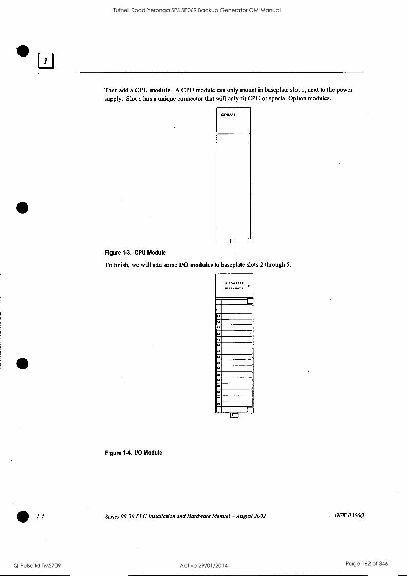
/-4
Then add a CPU module. A CPU module can only mount in baseplate slot 1, next to the power supply. Slot 1 has a unique connector that will only fit CPU or special Option modules.
CPU331
Lai
Figure 1-3. CPU Module
To finish, we will add some 1/0 modules to baseplate slots 2 through 5.
A12345670 1312345671
AS
AS
Al
AS
AS
Al
AA
SI
02
53
04
BS
BS
Al
a.
Figure 1-4. I/O Module
1.1
Series 90-30 PLC Installation and Hardware Manual - August 2002 GFK-0356Q
Tufnell Road Yeronga SPS SP069 Backup Generator OM Manual
Q-Pulse Id TMS709 Active 29/01/2014 Page 162 of 346

o
0
CO
0090000099000000009
2
dautumaam
d
0 [
; ;
..
11E11:1111E
0 WIL
E* 1111.11:11 17.
0000
11 fl
(i) I I
1r"'f
Tufnell Road Yeronga SPS SP069 Backup Generator OM Manual
Q-Pulse Id TMS709 Active 29/01/2014 Page 163 of 346

1-6
When assembled, the system will look like this:
GE Fanuc Own o. cm
A.11223.44:11.771:, A123458711, A511 22:44:11.74 PERES 9040 0 Pa
0 am
5A11222344551167711,
MOH CAPACITY POWER SUPPLY
PICORMANIMIll COMICILLER
r r
Figure 1-6. A Basic System
An assembly of baseplate and modules such as this one is called a "Rack."
What else would be needed to make this basic system functional?
To make this basic system functional, you would need:
Mounting. Safe, secure mounting for the PLC in a protective enclosure.
Wiring. This includes properly installed incoming power to the power supply, as well as
wiring from the I/O modules to field devices such as switches, sensors, solenoids, relays, etc.
Program. An application program for the PLC to run. This is developed with GE Fanuc PLC programming software.
What if the application requires more than five modules?
You could use a 10-slot baseplate, shown in the next picture:
'1I
110 Bus Expansion Connector
Figure 1.7. Ten-Slot Rack
Series 90-30 PLC Installation and Hardware Manual - August 2002 GFK-0356Q
Tufnell Road Yeronga SPS SP069 Backup Generator OM Manual
Q-Pulse Id TMS709 Active 29/01/2014 Page 164 of 346

ri What if the application requires more than ten modules?
GFK-0356Q
You can add one or more Expansion or Remote racks to this system. Some CPUs can support up to seven additional racks. If you added seven additional 10-slot racks, you could have 70 more modules.
Racks are interconnected in a "daisy-chain" cabling arrangement. This interconnection system is called the 1/0 Expansion Bus." The connections are made from one baseplate's I/0 Bus Expansion Connector (shown in the figure above) to the next one's. The I/0 Bus Expansion Cables, shown below, have a double connector on one end to facilitate these connections.
Female Connector
Male Connector
Figure 1-8. I/O Bus Expansion Cable
Male Connector
Chapter 1 Overview of the Series 90-30 PLC 1-7
Tufnell Road Yeronga SPS SP069 Backup Generator OM Manual
Q-Pulse Id TMS709 Active 29/01/2014 Page 165 of 346

1-8
The next figure shows a system that has a CPU baseplate, one Expansion rack and three Remote racks. Notice that the last rack, the one at the end of the I/O Expansion Bus, must be terminated. A convenient way of terminating the bus is with an IC693ACC307 I/O Bus Terminator Plug, as
shown.
CPU BASEPLATE
EXPANSION BASEPLATE
MAXIMUM DISTANCE FROM CPU = 50 FEET
(15 METERS)
REMOTE BASEPLATE
REMOTE BASEPLATE
REMOTE BASEPLATE
MAXIMUM DISTANCE FROM CPU = 700 FEET
(213 METERS)
M111111111'
MI111111111
psimumill
1711111i
Figure 1-9. Connecting Expansion and Remote Baseplates
1-
What is the Difference Between Expansion and Remote baseplates?
I/O BUS TERMINATOR
PLUG IC693ACC307
The main factor to consider is distance. How far will the baseplate be from the CPU baseplate? If the cabling distance from the CPU baseplate is 50 feet (15 meters) or less, use an Expansion baseplate. The Expansion baseplate is preferable because of its higher communication speed with the CPU baseplate. However, if a baseplate must be located where it requires a cabling distance from the CPU rack in excess of 50 feet, an Expansion baseplate will not work - a Remote baseplate must be used. The limit for a Remote baseplate is a cabling distance of 700 feet (213 meters) from the CPU baseplate to the farthest Remote baseplate.
Series 90-30 PLC Installation and Hardware Manual - August 2002 GFK-0356Q
Tufnell Road Yeronga SPS SP069 Backup Generator OM Manual
Q-Pulse Id TMS709 Active 29/01/2014 Page 166 of 346
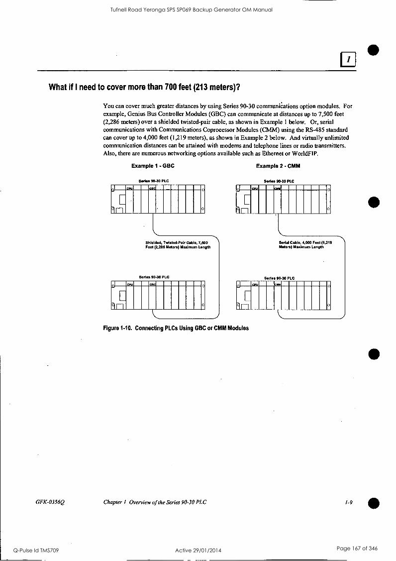
What if I need to cover more than 700 feet (213 meters)?
GFK-0356Q
You can cover much greater distances by using Series 90-30 communications option modules. For example, Genius Bus Controller Modules (GBC) can communicate at distances up to 7,500 feet (2,286 meters) over a shielded twisted-pair cable, as shown in Example 1 below. Or, serial communications with Communications Coprocessor Modules (CMM) using the RS-485 standard can cover up to 4,000 feet (1,219 meters), as shown in Example 2 below. And virtually unlimited communication distances can be attained with modems and telephone lines or radio transmitters. Also, there are numerous networking options available such as Ethernet or WorldFIP.
Example 1 - GBC
Series 90-30 PLC
11111111111 0
Shielded, Twisted-Pair Cable, 7,500 Feet (2,288 Meters) Maximum Length
Series 90-30 PLC Iinimmomm 0
Example 2 - CMM
Series 90-30 PLC
MINIM 0 Serial Cable, 4,000 Feet (1,219 Meters) Maximum Length
Series 90-30 PLC
Figure 1.10. Connecting PLCs Using GBC or CMM Modules
0
Chapter 1 Overview of the Series 90-30 PLC 1-9
Tufnell Road Yeronga SPS SP069 Backup Generator OM Manual
Q-Pulse Id TMS709 Active 29/01/2014 Page 167 of 346
Chapter
2 Installation
This chapter discusses installation details only. Other information about the products such as hardware descriptions and specifications, is covered in the applicable chapters.
Important Note Series 90-30 PLCs must be mounted in a protective enclosure.
The installation instructions described in this chapter apply to PLC installations that do not require special procedures for noisy or hazardous environments. For installations that must conform to more stringent requirements (such as CE Mark), see GFIC-1179, Installation Requirements for Conformance to Standards. Also see GFK-0867, GE Fanuc Product Agency Approvals, Standards, General Specifications.
Receiving your Products - Visual Inspection
When you receive your Series 90-30 PLC system, carefully inspect all shipping containers for damage that may have occurred during shipping. If any part of the system is damaged, notify the carrier immediately. The damaged shipping container should be saved as evidence for inspection by the carrier.
As the consignee, it is your responsibility to register a claim with the carrier for damage incurred during shipment. However, GE Fanuc will fully cooperate with you if such action is necessary.
Pre-installation Check
After unpacking Series 90-30 PLC racks, cables, modules, etc., record all serial numbers. Serial numbers are printed on the module packaging. Serial numbers are required to make a claim during the warranty period of the equipment. All software product registration cards should be completed and returned to GE Fanuc. See "Module Features" in this chapter for location of module serial numbers. See "Common Baseplate Features" in chapter 3 for location of baseplate serial numbers.
You should verify that all components of the system have been received and that they agree with your order. If the parts received do not agree with your order, call Programmable Control Customer Service at 1-800-432-7521. A Customer Service representative will provide further instructions.
If you require assistance with your installation, GE Fanuc's Technical Support department offers expert help. Call the support number for your area from the list in Chapter 13, "Maintenance and Troubleshooting." The GE Fanuc web site support address is www.gefanuc.com/support/plc.
Warranty Claims
Record the serial number of the defective item and contact your distributor for instructions.
GFK-0356Q 2-1
Tufnell Road Yeronga SPS SP069 Backup Generator OM Manual
Q-Pulse Id TMS709 Active 29/01/2014 Page 168 of 346

Working with Series 90-30 Modules
Module Features
O
0 0 0 10
V
IC693CPUxxx CPU MODULE 25 MHZ
LISTED 0 XXXXXXX
123456789
1E1811111 123456789
000 0
62)
Figure 2-1. Features of Series 90.30 Module
1. Pivot hook 2. Circuit board holding tabs (two on each side of module) 3. Catalog number and description section of label (Includes MAC address for CPU374.) 4. Certification (UL, CE, etc.) section of label 5. Module connector - plugs into baseplate backplane connector 6. Release lever - spring loaded 7. Ventilation openings in module case (top and bottom) 8. Front cover holding tabs (two on each side of module) 9. Front cover (shown) or terminal board (for I/O modules). 10. Front cover faceplate or hinged cover for terminal board. 11. Lens cap (some modules do not have). 12. Lens cap holding tabs (one on each side of module) 13. Module label 14. Serial Number - used to determine module warranty status. (On some modules, the Serial
Number may be on a small tag on the back of the module.)
2-2 Series 90-30 PLC Installation and Hardware Manual - August 2002 GFK-0356Q
Tufnell Road Yeronga SPS SP069 Backup Generator OM Manual
Q-Pulse Id TMS709 Active 29/01/2014 Page 169 of 346

Installing a Module
Warning
Do not insert or remove modules with power applied. This could cause the PLC to stop or malfunction. Injury to personnel and damage to the module or baseplate may result. Also, attempts to force a module into an improper slot type will result in damage to the module and/or the baseplate. Modules will mount in the correct slot type easily, with a minimum of force.
Use the following instructions as a guide when inserting a module into a baseplate slot.
Check that module catalog number matches slot configuration. Each slot is, or will be, assigned a particular module type during configuration. A Power Supply module must be installed in the left end unnumbered slot only, and a CPU module and some special Option modules can only be installed in Slot 1 of a CPU baseplate. I/O Modules and most Option modules install in slots numbered 2 and higher.
Grasp the module firmly with terminal board toward you and with rear pivot hook facing away from you.
Align the module with the desired baseplate slot and connector. Tilt the module upwards so
that top rear pivot hook of the module engages the baseplate's top module retainer.
Swing the module downward until the module's connector engages the baseplate's backplane connector, and the release lever on the bottom of the module snaps into place in the baseplate's bottom module retainer.
Visually inspect the module to be sure that it properly seated.
Figure 2.2. Installing a Module
GFK-0356Q Chapter 2 Installation 2-3
Tufnell Road Yeronga SPS SP069 Backup Generator OM Manual
Q-Pulse Id TMS709 Active 29/01/2014 Page 170 of 346

Removing a Module
Warning
Do not insert or remove modules with power applied. This could cause the PLC to stop or malfunction. Injury to personnel and damage to the module or baseplate may result. Also potentially dangerous voltages from user devices may be present on a module's screw terminals even though power to the rack is turned off. Care must be taken any time that you are handling the module's removable terminal board or any wires connected to it.
If the module has wiring, remove the module's terminal board (NOTE: You do not have to unwire the terminal board) or cables. The procedure for removing a terminal board is described later in this section.
Locate the release lever at the bottom of the module and firmly press it up, towards the module.
While holding the module firmly at its top and fully depressing release lever, swing (pivot) the module upward (release lever must be free of its retaining slot).
Disengage pivot hook at the top rear of the module by moving the module up and away from the baseplate.
PIVOT HOOK
\\.4,
a43056
Figure 2-3. Removing a Module
PRESS RELEASE LEVER
Note
Modules in expansion or remote baseplates can be added, removed, or replaced while the PLC is in RUN mode if power is first removed from the expansion or remote baseplate. I/O data to/from this baseplate will not be updated while power is removed.
2-4 Series 90-30 PLC Installation and Hardware Manual - August 2002 GFK-0356Q
Tufnell Road Yeronga SPS SP069 Backup Generator OM Manual
Q-Pulse Id TMS709 Active 29/01/2014 Page 171 of 346

a Installing a Module's Terminal Board
Note: Modules IC693MDL730F (and later) and IC693MDL731F (and later) have special terminal boards that are equipped with holding screws. For Installation and Removal instructions, please see the section "Installing and Removing Terminal Boards with Holding Screws" later in this chapter.
To install a terminal board (circled numbers refer to drawing below):
Hook the pivot hook 0, located on the bottom of the terminal board, to the lower slot on the module.
Push the terminal board toward the module 0 until it snaps into place.
Open the terminal board cover 0 and ensure that the latch on the module is securely holding the terminal board in place.
Caution
Compare the module catalog number on the label on the back of the hinged door (see Figure 2-6) and the label on the side of the module (see below) to ensure that they match. If a wired terminal board is installed on the wrong module type, damage to the module may occur when the system is powered up.
Module Label
a43062
REFER TO TEXT FOR INSTALLATION PROCEDURE
Figure 2-4. Installing an 110 Module's Terminal Board
Chapter 2 Installation 2-5
Tufnell Road Yeronga SPS SP069 Backup Generator OM Manual
Q-Pulse Id TMS709 Active 29/01/2014 Page 172 of 346

Removing a Module's Terminal Board
To remove a terminal board:
Open the plastic terminal board cover.
Push up on the jacking lever to release the terminal block.
Grasp pull-tab and pull it towards you until contacts have separated from module housing and bottom pivot hook has disengaged.
Figure 2.5. Removing a Module's Terminal Board
2-6 Series 90-30 PLC Installation and Hardware Manual - August 2002 GFK-0356Q
Tufnell Road Yeronga SPS SP069 Backup Generator OM Manual
Q-Pulse Id TMS709 Active 29/01/2014 Page 173 of 346

GFK-0356Q
I/O Module Terminal Board Posts
The terminal board has three posts on the left side. The top and bottom posts hold the terminal board cover in place. The middle post keeps the terminal board wiring in place. If you do not
require it to hold the wiring in place, the middle post can be easily snapped off. (Be careful that you do not inadvertently snap it off if you need it to keep your wiring in place.)
Installing and Removing Terminal Boards with Holding Screws
Discrete output modules IC693MDL730F (and later) and IC693MDL731F (and later) have a
special terminal board that is equipped with holding screws, shown in the figure below. These screws prevent the terminal board-to-module connections from deteriorating in applications where the PLC is subjected to severe vibration .
Holding Screw
A12345678 F
B1234.5678
11-1 r
Removeable Terminal Board
Holding Screw
I
t± 0
0 0 0 0
II F0 0
-J
Hinged Cover
L -
IlLr- Module Catalog Number
Figure 2-6. Terminal Board with Holding Screws
Removing: To Remove these terminal boards, first loosen the two holding screws on the front
of the terminal board, then follow the standard removal instructions in the section "Removing an I/O Module's Terminal Board." The holding screws are held captive in the terminal board
and do not have to be completely removed.
Installing: To install these terminal boards, follow the standard installation instructions in the
section "Installing an I/O Module's Terminal Board," then tighten the two holding screws to 8
to 10 inch-pounds (1 Newton-meter) of torque.
Chapter 2 Installation 2-7
Tufnell Road Yeronga SPS SP069 Backup Generator OM Manual
Q-Pulse Id TMS709 Active 29/01/2014 Page 174 of 346

Baseplate Mounting
Warning
Be sure to follow baseplate grounding instructions in this chapter. Failure to properly ground the PLC can result in improper operation, damage to equipment, and injury to personnel.
Mounting a Baseplate to a Panel
Use four good-quality 8-32 x 1/2 (4 x 12mm) machine screws, lock washers and flat washers. Install the screws in four tapped holes. The "Baseplates" chapter has the applicable dimensions and mounting clearances. Alternately, 10-slot baseplates can be mounted in standard 19-inch racks by using the appropriate adapter. This is also discussed in the "Baseplates" chapter.
A vertical mounting orientation is preferred for maximum heat dissipation. Other mounting orientations will require derating the Power Supply current capabilities. See Chapter 12,
"System Design," for details.
All baseplates must be grounded. The "Baseplate Safety Grounding" section of this chapter has details.
The Rack Number Selection switch must be set on each Expansion or Remote baseplate. A CPU baseplate does not require this switch. Rack numbers should be assigned by the system designer. Failure to set the Rack Number Selection switches properly will result in system malfunction. See the "Baseplates" chapter for details on setting these switches.
Mounting a Baseplate to a 19" Rack
Two optional Baseplate Adapter Brackets allow a 10-slot baseplate to be mounted in a 19 inch rack. Each baseplate installation requires only one of the adapter brackets.
IC693ACC308 Front Mount Adapter Bracket. Used to mount a baseplate to the front face of a 19" rack. Install the adapter bracket by inserting the tabs at the top and bottom of the adapter bracket into the corresponding slots at the top and bottom of the plastic baseplate cover. NOTE: Although Figure 2-7 shows the plastic baseplate cover removed, this is for illustration purposes only. It is not necessary to remove the cover to install the bracket. With the bracket in place, insert and tighten the two screws (included with the bracket) through the back of the baseplate holes into the threaded holes in the bracket.
2-8 Series 90-30 PLC Installation and Hardware Manual - August 2002 GFK-0356Q
Tufnell Road Yeronga SPS SP069 Backup Generator OM Manual
Q-Pulse Id TMS709 Active 29/01/2014 Page 175 of 346

GFK-0356Q
IC693ACC313 Recessed Mount Adapter Bracket. Used to recess mount a baseplate inside
a 19" rack. A baseplate mounts on the rear panel of this adapter bracket using four 8-32
(4mm) screws, nuts, lock washers, and flat washers. The Adapter Bracket bolts through its
four slotted holes to the face of the 19" rack using applicable hardware (lock washers recommended).
GHT SIDE OF BASEPLATE
Insert two screws (1 at top; 1 at bottom) - from back of base unit through base unit
and brackeL Tighten screws to secure bracket to base unit.
Note: Baseplate is shown with cover removed for illustration purposes. it is not necessary to remove the baseplate cover to install the bracket.
Figure 2-7. IC693ACC308 Front Mount Adapter Bracket Installation
Dimensions for rack mounting a 10-slot baseplate with the IC693ACC308 Front Mount Adapter Bracket are shown in the following figure.
18.89 (480)
18.47 (469)
,c,
1
, I i
L L
r'
L
r
L
r
L
r
I-.
r
L
r
L L
r
L
__r- r U
DIMENSIONS IN INCHES (MILLIMETERS IN PARENTHESES)
Figure 2-8. Dimensions for 19-inch Rack Mounting Using IC693ACC308 Adapter Bracket
Chapter 2 Installation 2-9
Tufnell Road Yeronga SPS SP069 Backup Generator OM Manual
Q-Pulse Id TMS709 Active 29/01/2014 Page 176 of 346

U
I I - ---- - - - - - - - - - - - -. - _ - -.- ._ -. - -. - - - - - - - - --._ -
DIMENSIONS IN INCHES (MILLIMETERS IN PARENTHESES)
Figure 2.9. IC693ACC313 Recessed Mount Adapter Bracket
2-10 Series 90-30 PLC Installation and Hardware Manual - August 2002 GFK-0356Q
Tufnell Road Yeronga SPS SP069 Backup Generator OM Manual
Q-Pulse Id TMS709 Active 29/01/2014 Page 177 of 346

Grounding Procedures
System Grounding Procedures
GFK-0356Q
Warning
In addition to the following grounding information, we strongly urge that you follow all applicable codes that apply to your area. For example, in the United States, most areas have adopted the National Electrical Code standard and specify that all wiring conform to its requirements. In other countries, different codes will apply. For maximum safety to personnel and property you must follow these codes. Failure to do so can mean injury or death to personnel, damage to property, or both.
All components of a programmable logic control system and the devices it is controlling must be
properly grounded. This is particularly important for the following reasons.
A low resistance path from all parts of a system to earth minimizes exposure to shock in the
event of short circuits or equipment malfunction.
The Series 90-30 PLC system requires proper grounding for correct operation.
Ground Conductors
Ground conductors should be connected in a tree fashion with branches routed to a central
earth ground point, shown in the figure below. This ensures that no ground conductor carries
current from any other branch. This method is shown in the following figure.
Ground conductors should be as short and as large in size as possible. Braided straps or
ground cables (typically green insulation with a yellow tracer - AWG #12 (3.3 min') or larger)
can be used to minimize resistance. Conductors must always be large enough to carry the
maximum short circuit current of the path being considered.
PROGRAMMING DEVICE
0
SERIES 90-30 PLC CABINET
I RACK
I RACK1-°
1
MOTOR DRIVES AND OTHER ELECTRICAL
CONTROL EQUIPMENT
0
EARTH CENTRAL GROUND GROUND POINT
Figure 2-10. Recommended System Grounding
MACHINERY
NOTE SIGNAL AND POWER
CONNECTIONS ARE NOT SHOWN
Chapter 2 Installation 2-11
Tufnell Road Yeronga SPS SP069 Backup Generator OM Manual
Q-Pulse Id TMS709 Active 29/01/2014 Page 178 of 346

Series 90-30 PLC Equipment Grounding
Equipment grounding recommendations and procedures are listed below. These grounding procedures must be properly followed for safe, proper operation of your Series 90-30 PLC system.
Baseplate Safety Grounding
The following recommendations are offered, but applicable safety codes for your area or equipment type should also be consulted. The baseplate's metal back must be grounded using a separate conductor; the baseplate mounting screws are not considered to an acceptable ground connection by themselves. Use a minimum AWG #12 (3.3 mm2) wire with a ring terminal and star lock washer under the head of one of the baseplate's two lower mounting holes. These two holes have openings to the side to allow connecting a wire and ring terminal under the head of a mounting screw. Connect the other end of this ground wire to a tapped hole in the panel that the baseplate is mounted to, using a machine screw, star lock washer, and flat washer. Alternately, if your panel has a ground stud, it is recommended you use a nut and star lock washer for each wire on the ground stud to ensure adequate grounding. Where connections are made to a painted panel, the paint should be removed so clean, bare metal is exposed at the connection point. Terminals and hardware used should be rated to work with the aluminum baseplate material.
AWG #12 or Larger Wire
USER PROGRAM
ARO REGISTER VALUES MAY BE
LOST IF POWER SUPPLY IS
REMOVED FOR LONGER 'MAN
1 HOUR
Screw, Star Lock washer, Rat Washer, Ring Terminal, installed In tapped hole.
Paint Removed .
From Panel Here
Figure 2.11. Baseplate Grounding
Warning
Alternate location for Ground connection
All baseplates must be grounded to minimize electrical shock hazard. Failure to do so can result in severe personal injury.
2-12 Series 90-30 PLC Installation and Hardware Manual - August 2002 GFK-0356Q
Tufnell Road Yeronga SPS SP069 Backup Generator OM Manual
Q-Pulse Id TMS709 Active 29/01/2014 Page 179 of 346

GFK-0356Q
All baseplates grouped together in a Series 90-30 PLC system must have a common ground connection. This is especially important for baseplates that are not mounted in the same control cabinet.
Grounding 19" Rack-Mounted Baseplates
There are two Adapter Brackets used for mounting a 10-slot Series 90-30 baseplate to a 19" Rack.
Regardless of which of the two Adapter Brackets is used, the 19" Rack should be grounded as per the instructions in "System Grounding Procedures," including Figure 2-10. (For details on the Adapter Brackets, see the "Mounting a Baseplate to a 19" Rack" section earlier in this chapter.)
Nineteen-Inch Rack-mounted PLC baseplates should be grounded according to the guidelines in
the "Baseplate Safety Grounding" section, using a separate ground wire from the PLC baseplate as
shown in the previous figure (Fig. 2-11).
If using the Recessed Mount Adapter Bracket (IC693ACC313), the ground wire can be installed as shown in Figure 2-11 with the ground attached to the Recessed Mount Adapter Bracket. An additional ground wire connecting the Adapter Bracket to a solid chassis ground on the 19" Rack should be installed. Use the same or equivalent hardware and paint removal scheme as shown in Figure 2-11.
If using the Surface Mount Adapter Bracket (IC693ACC308), the ground wire should be run from the baseplate as shown in Figure 2-11, to a solid chassis ground on the 19" Rack. Use the same or equivalent hardware and paint removal scheme as shown in Figure 2-11.
Programmer Grounding
For proper operation, the computer (programmer) running the PLC software must have a ground connection in common with the CPU baseplate. Normally, this common ground connection is
provided by ensuring that the programmer's power cord is connected to the same power source (with the same ground reference point) as the baseplate. If it is not possible to ensure this common ground scheme, use a port isolator (IC690ACC903) between the programmer and PLC serial
connection. If the programmer ground is at a different potential than the PLC ground, a shock hazard could exist. Also, damage to the ports or converter (if used) could occur when the programmer serial cable is connected between the two.
Warning
Failure to follow programmer grounding recommendations could result in personal injury, equipment damage, or both.
Chapter 2 Installation 2-13
Tufnell Road Yeronga SPS SP069 Backup Generator OM Manual
Q-Pulse Id TMS709 Active 29/01/2014 Page 180 of 346

Module Shield Grounding
In general, the aluminum PLC baseplate is used for module shield grounding. On some Series 90-30 modules, shield connections to the user terminal connector on the module are routed to the baseplate through the module's backplane connector. Other modules, such as CPUs 351, 352, 363, 364, and 374 require a separate shield ground. These are discussed in the next several sections.
Shield Grounding Information for CPUs with External Port Connections
CPUs with external port connections, the 351, 352, 363, 364, and 374 must have a separate shield ground connection to provide shielding for these ports. Because the design of the ground connection for the CPU351 and 352 is different from that of the CPU363, 364, and 374, each grounding method is discussed in a separate section.
CPU351 and 352 Shield Grounding
The CPU 351 or 352 module must be connected to frame ground at the slot where it is installed. Two methods are provided for making this ground connection. Each CPU comes with an EMC Grounding Kit (44A737591-G01) that contains a ground wire, grounding bracket, and screws.
1. The connection from the CPU to frame ground can be made using the ground wire (part number 44A735970-001R01) that comes with the module in the EMC Grounding Kit. This wire has a stab-on connector on one end for connection to a mating terminal on the bottom of the CPU, and a ring terminal on the other end for connection to a grounded enclosure. Where the ring terminal contacts a painted enclosure panel, either a star lock washer can be installed between the terminal and the panel to cut through the paint, or the paint can be scraped away down to clean, bare metal to ensure a good contact. Note: The star lock washer method is suitable for a shield ground, but not suitable for a safety ground.
Figure 2-12. CPU 351 or 352 - Attaching Shield Ground Wire
2-14 Series 90-30 PLC Installation and Hardware Manual - August 2002
MOUNT ON GROUNDED ENCLOSURE
MI TAPPED HOLE
REMOVE PAINT UNDER RING TERMINAL OR INSTALL STAR LOCK WASHER BETWEEN TERMINAL AND PANEL
GFK-0356Q
Tufnell Road Yeronga SPS SP069 Backup Generator OM Manual
Q-Pulse Id TMS709 Active 29/01/2014 Page 181 of 346

GFK-0356Q
2. The second method, which can be used for systems in noisy environments consists of installing. the green ground wire and the optional grounding bracket (part number 44C715646-001R01). This bracket attaches to the CPU using two #4 thread-rolling screws (part number N666P9004B6) and to the grounded enclosure using two #6 thread-rolling screws (part number N666P13006B6). Two holes must be drilled in the enclosure for mounting this bracket. Also, if the bracket will be attached to a painted surface, the paint should be removed down to bare metal under the bracket to ensure good contact between the bracket and the surface. See the next figure.
USE 2 54 THREAD ROLLING SCREWS
(N666P900486)
USE 2 NS THREAD ROLLING SCREWS
046116P1300686
MOUNT ON GROUNDED ENCLOSURE
PAINT REMOVED WHERE BRACKET MOUNTS TO PANEL
Figure 2-13. CPU 351 or 352 - Mounting the Shield Grounding Bracket and Wire
Note: When the grounding bracket is used, pin 1 of the cable connector that plugs into the Port 2
connector should not be connected. A metal connector shell must be used on the cable for this port, and the cable shield must be terminated at the metal shell instead of pin 1 of the connector.
Chapter 2 Installation 2-15
Tufnell Road Yeronga SPS SP069 Backup Generator OM Manual
Q-Pulse Id TMS709 Active 29/01/2014 Page 182 of 346

CPU363, CPU364, and CPU374 Shield Grounding
The CPU363, CPU364, and CPU374 modules must be connected to frame ground at the slot where they are installed. Each module comes with a grounding wire for this purpose. These modules do not support or require the use of a grounding bracket. If the ring terminal on the grounding wire is to be mounted to a painted surface, remove the paint under the ring terminal to ensure good contact, or place a star lock washer between the ring terminal and the painted surface. See the next figure. Note: The star lock washer method is suitable for a shield ground, but not suitable for a safety ground.
Acs.T*ICTI'R./
CPU363, CPU364, or CPU374
Figure 2-14. CPU 363, CPU364, or CPU374 - Attaching Ground Wire
Additional Modules with Shield Grounding Requirements
MS TAPPED HOLE
REMOVE PAINT UNDER RING TERMINAL OR INSTALL STAR LOCK WASHER BETWEEN RING TF-RININAL AND PANEL
Some of the Series 90-30 Option modules, such as the FIP Remote I/O Scanner (IC693BEM330), and DSM modules (IC693DSM302 and IC693DSM314) also have shield grounding requirements. These modules come equipped with suitable grounding hardware. Please refer to each module's user's manual for grounding instructions. Appendix G contains a product to publication cross- reference to help you identify the correct manual.
2-16 Series 90-30 PLC Installation and Hardware Manual - August 2002
S
GFK-0356Q
Tufnell Road Yeronga SPS SP069 Backup Generator OM Manual
Q-Pulse Id TMS709 Active 29/01/2014 Page 183 of 346

General Wiring Guidelines
GFK-0356Q
Warning
In addition to the following wiring suggestions, we strongly urge that you follow all wiring and safety codes that apply to your area or your type of equipment. For example, in the United States, most areas have adopted the National Electrical Code standard and specify that all wiring conform to its requirements. In other countries, different codes will apply. For maximum safety to personnel and property you must follow these codes. Failure to do so can lead to personal injury or death, property damage or destruction, or both.
Color Coding Wires
These color codes are commonly used in industrial equipment manufactured in the United States. They are cited here as a reference. Where they are in conflict with codes that apply to your area or your type of equipment, you should follow your applicable codes instead. Besides satisfying code requirements, wire color coding makes testing and troubleshooting safer, faster, and easier.
Green or green with stripe- Ground
Black - Primary AC
Red - Secondary AC
Blue - DC
White - Common or neutral
Yellow - Secondary power source not controlled by the main disconnect. Alerts maintenance personnel that there may be power present (from an external source) even if the equipment is disconnected from its main power source.
Wire Routing
To reduce noise coupling among PLC wires, it is recommended you keep electrically noisy wiring, such as AC power wiring and Discrete Output Module wiring, physically separated from low-level signal wiring such as DC and Analog Input module wiring or communications cables. This can be
accomplished by grouping separately, where practical, the following categories of wiring:
AC power wiring. This includes the AC input to the PLC power supply, as well as other AC devices in the control cabinet.
Analog Input or Output Module wiring. This should be shielded to further reduce noise coupling. See the Series 90-30 I/O Module Specifications Manual, GFK-0898 for details.
Discrete Output Module wiring. These often switch inductive loads that produce noise spikes when switched off.
DC Input Module wiring. Although suppressed internally, these low-level inputs should be further protected against noise coupling by observing these wiring practices.
Communications Cables. Wiring such as Genius Bus or serial cables should be kept away from noise-producing wiring.
Chapter 2 Installation 2-17
Tufnell Road Yeronga SPS SP069 Backup Generator OM Manual
Q-Pulse Id TMS709 Active 29/01/2014 Page 184 of 346

Where AC or Output wiring bundles must pass near noise-sensitive signal wiring bundles, avoid running them beside each other. Route them so that, if they have to cross, they do so at a right angle. This will minimize coupling between them.
Grouping Modules to Keep Wires Segregated
If practical, grouping similar modules together in the PLC racks can help keep wiring segregated. For example, one rack could contain only AC modules, and a different rack only DC modules, with further grouping in each rack by input and output types. For smaller systems, as an example, the left end of a rack could contain Analog modules, the middle could contain DC modules, and the right end could contain AC modules.
Discrete I/O Module Connection Methods
For modules with 16 points or less, the standard method is to use the removable terminal board which comes with these modules. The removable terminal board makes it easy to prewire field wiring to the user supplied input and output devices, and to replace modules in the field without disturbing existing field wiring.
Some discrete 16-point I/O modules can be used with an optional Terminal Block Quick Connect (TBQC) assembly. This assembly contains a module faceplate, with built-in connector, that replaces the removable terminal board. The assembly also contains a DIN-rail mounted terminal block and a cable to connect the module to the terminal block. The advantage of this method is that it saves about two hours of wiring time per module compared with hand wiring from a module's removable terminal board to a user-supplied, panel-mounted terminal block or strip.
Older 32-point I/O modules have one 50-pin connector on the front of the module that is either connected by a cable with a connector on each end to a Weidmuller panel-mounted terminal block (Weidmuller catalog no. 912263), or is connected by a cable with stripped, tinned leads to a user-supplied terminal block or strip.
Newer 32-point I/O modules have two 24-pin connectors on the front of the module. These module may be wired in one of three ways. (1) Use a pair of cables (IC693CBL327/328 - see data sheet in "Cables" chapter) to connect the module to a user-supplied, panel-mounted terminal block or strip. These cables have a 24-pin connector on one end, and stripped, tinned leads with wire markers on the other end. (2) Use a pair of dual-connector cables to connect the module to a Terminal Block Quick Connect (TBQC) terminal block (IC693ACC377). See Appendix H for details. (3) Make your own custom cables. Instructions are found in the IC693CBL327/328 data sheet in Chapter 10.
Connections to I/O Module Terminal Boards
Series 90-30 PLC I/O terminal boards have either 10 or 20 screw terminals that will accept from two AWG #22 (0.36 mm2) to two AWG #16 (1.3 mm2), or one AWG #14 (2.1 mm2) copper 90°C (194°F) wire(s). Each terminal can accept solid or stranded wires, but the wires into any given terminal should be the same type (both solid or both stranded) to ensure a good connection. Wires are routed to and from the terminals out of the bottom of the terminal board cavity. The suggested torque for the I/O terminal board connection screws is from 9.6 in-lbs to 11.5 in-lbs (1.1-1.3 Newton-meters).
2-18 Series 90-30 PLC Installation and Hardware Manual - August 2002 GFK-0356Q
Tufnell Road Yeronga SPS SP069 Backup Generator OM Manual
Q-Pulse Id TMS709 Active 29/01/2014 Page 185 of 346

For 24 volt DC input modules, an internal 24 volt power connection is provided on the terminal board to supply a limited number of input devices. Also, a 24 volt DC output is available on the power supply module's terminal board to supply a limited number of output devices.
Terminal Block Quick Connect Installation for 16-Point Discrete Modules
The Terminal Block Quick Connect (TBQC) Assembly is an option for certain Series 90-30 discrete I/O modules. See Appendix H for more information.
Remove standard terminal board from module.
Install TBQC faceplate (it has a 24-pin connector).
Mount the TBQC terminal block. It has a 24-pin connector and a terminal strip, and mounts on a standard 35 mm DIN-rail.
Connect a TBQC cable between the TBQC faceplate connector on the module and the connector on the TBQC terminal block.
Wire I/O devices to the terminal block.
Installation of 32-Point Discrete, 50-Pin Connector Modules
GFK-0356Q
These 50-Pin modules are an older design and are not generally used on new systems, unless to fulfill standardization requirements. They are mainly used as replacements for existing installations. For new installations, we recommend the dual 24-pin connector style because they have additional features not found on the older modules (LED indicators, TBQC), and it is much easier to fabricate custom-length cables for them. Installation information is provided here for the
convenience of those still using these modules.
Using Weidmuller #912263 Terminal Block
Note: The TBQC is not available for these modules, but you may purchase a Weidmuller #912263 from your electronics distributor for this application.
Mount the Weidmuller#912263 terminal block. It has a 50-pin connector and a terminal strip, and mounts on a standard 35 mm DIN-rail.
Connect an IC693CBL306/307 cable between the module's faceplate connector and the connector on the Weidmuller terminal block. See Chapter 10 for cable data.
Wire I/O devices to the terminal block. See the Series 90-30 PLC I/O Module Specifications Manual, GFK-0898, for pin-out information.
Chapter 2 Installation 2-19
Tufnell Road Yeronga SPS SP069 Backup Generator OM Manual
Q-Pulse Id TMS709 Active 29/01/2014 Page 186 of 346

Using a Generic Terminal Block or Strip
Mount terminal block/strip to the enclosure panel.
Connect an 1C693CBL308 or 309 cable, or a custom made cable, to the module's faceplate connector and wire the stripped ends of the cable to the terminal block/strip. See Chapter 10 for cable data.
Wire 1/0 devices to the terminal block/strip.
Direct Method
Connect an IC693CBL308 or 309 cable, or a custom made cable, to the module's faceplate connector and wire the stripped ends of the cable directly to the field devices. See Chapter 10 for cable data. See the Series 90-30 PLC I/O Module Specifications Manual, GFK-0898, for pin-out information.
Installation of Discrete 32-Point, Dual 24-Pin Connector Modules
Using a TBQC
Mount two TBQC terminal blocks. Each has a 24-pin connector and a terminal strip, and mounts on a standard 35 mm DIN -rail.
Connect a pair of TBQC cables (IC693CBL329 - 334) between the module's faceplate connector and the connectors on the two TBQC terminal blocks. Note that both a right side and left side cable is required. See Appendix H for a list of cables.
Wire I/O devices to the terminal blocks. See the Series 90-30 PLC I/O Module Specifications Manual, GFK-0898, for pin-out information.
The Terminal Block Quick Connect (TBQC) Assembly is an option for certain Series 90-30 discrete I/O modules. See Appendix H for more information.
With a Generic Terminal Block/Strip
Mount terminal block/strip to the enclosure panel.
Connect an IC693CBL327/328 cables, or a custom made cables, to the module's faceplate connectors, and wire the stripped ends of the cables to the terminal block/strip. Note that both a right side and left side cable is required. See Appendix H for a list of cables. See Chapter 10 for cable data sheets.
Wire I/O devices to the terminal block/strip. See the Series 90-30 PLC I/O Module Specifications Manual, GFK-0898, for pin-out information.
2-20 Series 90-30 PLC Installation and Hardware Manual - August 2002 GFK-0356Q
Tufnell Road Yeronga SPS SP069 Backup Generator OM Manual
Q-Pulse Id TMS709 Active 29/01/2014 Page 187 of 346

Direct Method
Connect an IC693CBL327/328 cable, or a custom made cable, to the module's faceplate connectors, and wire the stripped ends of the cable directly to the field devices. See Chapter 10 for cable data. See the Series 90-30 PLC I/O Module Specifications Manual, GFK-0898, for pin-out information.
General Wiring Methods for Analog Modules
Twisted, shielded instrumentation cable is strongly recommended for analog module input or output signal connections. Proper grounding of the shield is also important. For maximum electrical noise suppression, the cable shield should only be grounded at one end of the cable. For Input modules, ground the end that is in the noisiest environment (which often is at the field device end). For Output modules, ground at the module end. See GFK-0898, Series 90-30 PLC I/O Module Specifications, for more shield grounding information.
Analog Input Module Wiring Methods
GFK-0356Q
Correcting electrical noise problems can sometimes be a trial-and-error routine. However, in general, it is generally best to ground the cable shield as close to the source of the noise as possible, which is usually at the device end. In troubleshooting noise problems, sometimes it is beneficial to experiment with the shield grounding point location. Remember, the cable shield should be grounded at one end only. Also, it is best to keep the length of stripped cable leads as short as
possible to minimize the length of unshielded conductors that will be exposed to the noisy environment. See the Series 90-30 PLC I/O Module Specifications Manual, GFK-0898 for additional details.
Using a Generic Terminal Block or Strip
Mount a terminal strip inside the control enclosure and run a shielded cable from the terminal strip to each input circuit on the module's terminal board terminals.
Connect each cable's shield to the metal panel next to the terminal strip. Do not connect the shields at the module end (cut shield off at module end of cable and insulate with shrink tubing).
Wire the field device to the terminal strip with a shielded cable, grounding the shield at the device end only (cut shield off at terminal strip end of cable and insulate with shrink tubing). Also, keep the length of exposed (outside of shield) leads at the terminal strip and device ends as short as possible.
Direct Method
Run a shielded cable from the field device (transducer, potentiometer, etc.) directly to the module.
Connect the conductors to the applicable screws on the module's terminal board.
Chapter 2 Installation 2-21
Tufnell Road Yeronga SPS SP069 Backup Generator OM Manual
Q-Pulse Id TMS709 Active 29/01/2014 Page 188 of 346

Ground the shield at the field device end, exposing a minimum amount of conductor to the noisy environment. Do not connect the shield at the module end (cut shield off at module end of cable and insulate with shrink tubing).
TBQC not Recommended for Analog Modules
The Terminal Block Quick Connect (TBQC) Assembly is not recommended for use with analog modules due to cable shielding requirements.
Analog Output Module Wiring
General
Each output should be connected using a good quality shielded wire with the cable shield grounded at the module end. See GFK-0898, Series 90-30 PLC I/O Module Specifications, for more information.
Using a Generic Terminal Block or Strip
Mount a terminal strip inside the control enclosure and run a shielded cable from the terminal strip to each output circuit on the module's terminal board terminals.
Ground each cable's shield at the module end only. Do not connect the shields at the terminal strip end (cut shields off at terminal strip end of cables and insulate with shrink tubing).
Wire the field device to the terminal strip with shielded cables, grounding the shields at the terminal strip end only (cut shields off at field device end of cables and insulate with shrink tubing). Also, keep the length of exposed (outside of shield) leads at the terminal strip and device ends as short as possible.
Direct Method
Run a shielded cable from each field device (transducer, potentiometer, etc.) directly to the module.
Connect the conductors to the applicable screws on the module's terminal board.
Ground the shield at the module end only, exposing a minimum amount of conductor to the noisy environment. Do not connect the shield at the device end (cut shield off at device end of cable and insulate with shrink tubing).
TBQC not Recommended for Analog Modules
The Terminal Block Quick Connect (TBQC) Assembly is not recommended for use with analog modules due to cable shielding requirements.
2-22 Series 90-30 PLC Installation and Hardware Manual - August 2002 GFK-0356Q
Tufnell Road Yeronga SPS SP069 Backup Generator OM Manual
Q-Pulse Id TMS709 Active 29/01/2014 Page 189 of 346

AC Power Source Connections
AC Input Wiring to AC/DC Power Supplies
GFK-0356Q
Warning
If the same AC power source is used to provide AC power to other baseplates in a Series 90-30 PLC System, ensure that all AC input connections are identical at each rack. Do not cross Line 1 (L1) and Line 2 (L2). A resulting difference in potential can injure personnel or cause damage to equipment. Each baseplate must be connected to a common ground.
Ensure that the protective cover is installed over all terminal boards. During normal operation with an AC power source either 120 VAC or 240 VAC is present on the AC Power Supply. The cover protects against accidental shock hazard which could cause severe or fatal injury to the operator or maintenance personnel.
Both the Standard (IC693PWR321) and High Capacity (IC693PWR330) AC/DC power supplies currently have six terminals for user connections. Early versions of some Series 90-30 power supplies had five terminals (see next figure). The wiring methods for both five-terminal and six- terminal types is similar, except that step 3 below does not apply to the five-terminal type.
The power supply terminal boards will accept one AWG #14 (2.1 mm2) or two AWG #16 (1.3 mm2) copper 75_ C (167_ F) wires. Each terminal can accept solid or stranded wires, but the wires in any given terminal should be the same type. The suggested torque for the power supply terminal board is 12 in-lbs (1.36 Newton-meters). Open the door protecting the terminal board and make the following connections from the AC power source, and ground connections (system grounding requirements are described in detail later in this chapter).
1. These are wide range supplies that can operate from an AC power source within the nominal range of 100 VAC to 240 VAC at 50/60 Hz. This may vary -15% to +10% for a total maximum range of 85 VAC to 264 VAC. These are auto-ranging supplies that do not require jumper or switch settings for selection of power source voltage.
2. Connect the hot and neutral wires or lines L1 and L2 to the upper two terminals on the terminal board. Connect the safety ground wire to the ground terminal, which is the third terminal from the top, and is marked with a ground symbol.
3. For power supplies with six terminals, the factory jumper between the 3rd and 4th terminals (see figure below), should be left in place for normal installations. However, this jumper must be removed and external surge suppressors installed in installations with a "Floating Neutral" input. Please see the section "Special Instructions for Floating Neutral (IT) Systems" later in
this chapter for details.
4. After all connections to Power Supply terminal board have been completed, the protective cover plate should be carefully reinstalled.
Chapter 2 Installation 2-23
Tufnell Road Yeronga SPS SP069 Backup Generator OM Manual
Q-Pulse Id TMS709 Active 29/01/2014 Page 190 of 346

Input Power
Factory Jumper
24 VDC Output For 1/0 Modules
I0
0 0
1 0 1
10
INPUT
100.240 VAC
50/6014Z 90VA
125 VDC. 50W
+ 24VDC OUTPUT 0.8A MAX.
Six-Terminal Board
Figure 2-15. Power Supply Terminal Boards
Power Supply Overvoltage Protection Devices
Input Power
24 VDC Output For I/O Modules
01 0 0
I 0 I
0
INPUT
100-240 VAC
50160912 90VA
125 VDC, 50W
O
Five-Terminal Board
24 VDC OUTPUT
0.85 MAX.
The overvoltage protection devices for this power supply are connected internally to pin 4 on the user terminal board. This pin is normally connected to frame ground (pin 3) with the supplied jumper strap which is installed at the factory. If overvoltage protection is not required or is supplied upstream, this feature can be disabled by leaving pin 4 unconnected by removing the jumper strap. Also, this jumper must be removed and external surge suppressors installed in installations with a "Floating Neutral" input, please see the following section "Special Instructions for Floating Neutral (IT) Systems" later in this chapter.
If you want to Hi-pot test this supply, overvoltage protection must be disabled during the test by removing the terminal board strap. Re-enable overvoltage protection after testing by reinstalling the strap.
Jumper Strap Connects Overvoltage Protection
Devices to Frame Ground
a47086
Screw Terminals on Terminal Board
Figure 2-16. Overvoltage Protection Devices and Jumper Strap
2-24 Series 90-30 PLC Installation and Hardware Manual - August 2002 GFK-0356Q
Tufnell Road Yeronga SPS SP069 Backup Generator OM Manual
Q-Pulse Id TMS709 Active 29/01/2014 Page 191 of 346
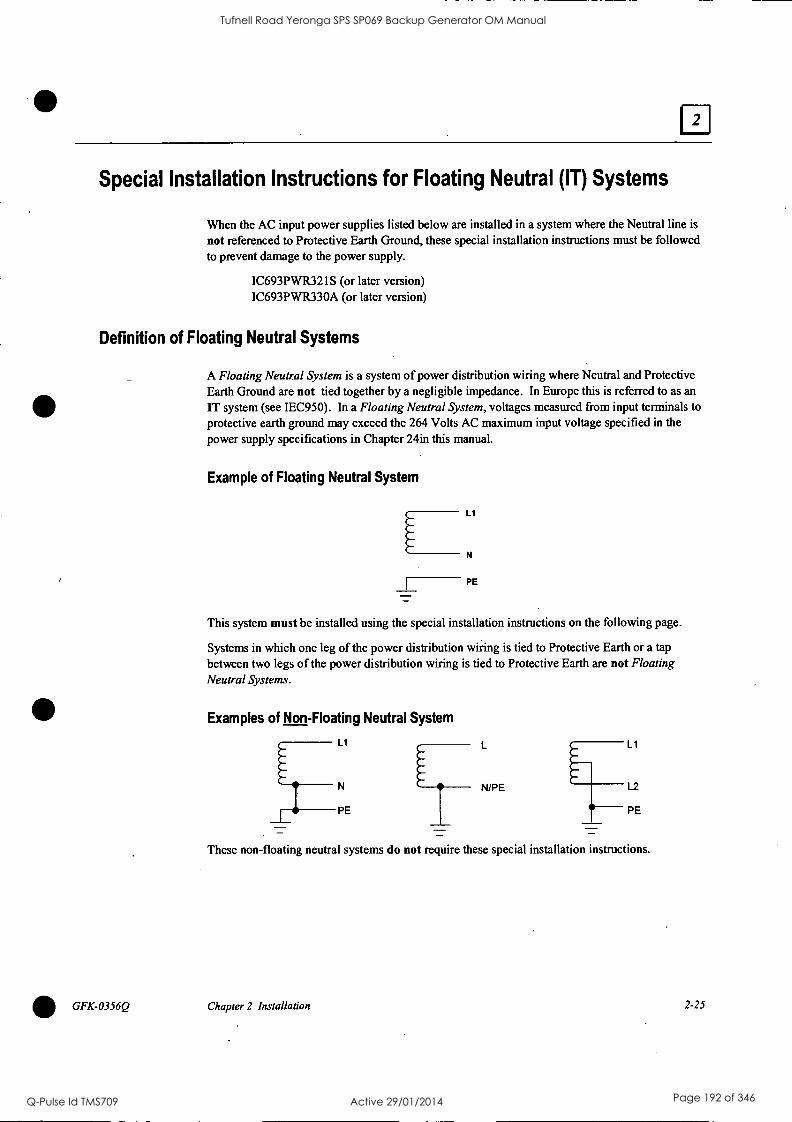
Special Installation Instructions for Floating Neutral (IT) Systems
When the AC input power supplies listed below are installed in a system where the Neutral line is
not referenced to Protective Earth Ground, these special installation instructions must be followed to prevent damage to the power supply.
IC693PWR321S (or later version) IC693PWR330A (or later version)
Definition of Floating Neutral Systems
GFK-0356Q
A Floating Neutral System is a system of power distribution wiring where Neutral and Protective Earth Ground are not tied together by a negligible impedance. In Europe this is referred to as an
IT system (see IEC950). In a Floating Neutral System, voltages measured from input terminals to
protective earth ground may exceed the 264 Volts AC maximum input voltage specified in the
power supply specifications in Chapter 24in this manual.
Example of Floating Neutral System
Ll
N
PE
This system must be installed using the special installation instructions on the following page.
Systems in which one leg of the power distribution wiring is tied to Protective Earth or a tap between two legs of the power distribution wiring is tied to Protective Earth are not Floating Neutral Systems.
Examples of Non-Floating Neutral System
Ll
N N/PE
PE
Ll
L2
PE
These non-floating neutral systems do not require these special installation instructions.
Chapter 2 Installation 2-25
Tufnell Road Yeronga SPS SP069 Backup Generator OM Manual
Q-Pulse Id TMS709 Active 29/01/2014 Page 192 of 346

Use These Special Installation Instructions for Floating Neutral Systems
1. The input power terminals should be wired according to the instructions in the "AC Power Source Connections" section of this chapter.
2. The factory installed jumper between terminals 3 and 4 of the Power Supply module must be removed if using one of the Power Supplies that have this feature. See the "Overvoltage Protection Devices" section of the "Power Supplies" chapter for details.
3. Voltage surge protection devices, such as MOVs, MUST be installed between the following terminals:
From L1 to earth ground
From L2 (Neutral) to earth ground
The voltage surge devices must be rated such that the system is protected from power line transients that exceed Line voltage + 100V +(N-PE), Ax
The expression N-PE refers to the voltage potential between neutral and Protective Earth (PE) ground.
For example, in a 240 Volt AC system with neutral floating 50V above earth ground, the transient protection should be rated at:
240V + 100y +50V = 390V
2-26 Series 90-30 PLC Installation and Hardware Manual - August 2002 GFK-0356Q
Tufnell Road Yeronga SPS SP069 Backup Generator OM Manual
Q-Pulse Id TMS709 Active 29/01/2014 Page 193 of 346

DC Power Source Connections
DC Input Wiring to AC/DC and DC-Only Power Supplies
DC Input power can range from 12 to 30 VDC for the 24 VDC supply, 18 to 56 VDC for the 24/48 VDC supply or 100 to 150 VDC for the 125 VDC supply. All Series 90-30 power supplies have DC input capabilities. The following connection information applies to all of them:
Connect the + and - wires from the power source to the top terminals on the terminal board (+ to the top terminal, - to the second terminal). Connect the third terminal from the top to system ground.
+24 VDC Output (All Supplies)
GFK-0356Q
The bottom two terminals are connected to the isolated 24 volt DC output that can be used to supply power to input circuits (within power limitations of the supply).
Warning
If the same DC input power source is used to provide power to two or more power supplies in a Series 90-30 PLC System, ensure that connection polarity is identical at each rack (top terminal + and second terminal -). Do not cross the Positive (+) and Negative (-) lines. A resulting difference in potential can injure personnel or cause damage to equipment. Also, each baseplate must be connected to a common system ground, described earlier in this chapter.
Chapter 2 Installation 2-27
Tufnell Road Yeronga SPS SP069 Backup Generator OM Manual
Q-Pulse Id TMS709 Active 29/01/2014 Page 194 of 346

Basic Installation Procedure
Note: Series 90-30 PLCs must be mounted in a protective enclosure. The enclosure should be capable of properly dissipating the heat produced by all of the devices mounted inside it.
For details on calculating heat dissipation, refer to Appendix F.
The system design, which includes producing the layout and wiring drawings, should be completed before beginning the installation procedure. This section offers a basic step-by-step approach to installing a Series 90-30 PLC system. Some steps refer to earlier sections of this chapter for additional details. An attempt was made to place the steps in an order that will make the process as efficient as possible. However, due to the wide variance in system designs, this order may not be the most efficient for your system, so you may wish modify this procedure to fit your needs.
1. Gather the schematics, layouts, prints, and other information for the job.
Warning
To avoid the possibility of electrical shock to personnel or damage to your PLC, we recommend that you shut off all power to the system before mounting and wiring the PLC. Also, keep all electronic components away from the area while drilling and tapping to keep metal chips and filings out of these sensitive components.
2. From the layout drawing, determine where the baseplate(s) will be mounted. Lay out the hole locations, either using the dimensions given on your layout drawing or from the "Baseplates" chapter of this manual.
3. Mark the hole locations for the baseplate safety ground wire (see "Baseplate Safety Ground" in this chapter).
4. Mark the hole locations for module shield ground connections (if any). See "Module Shield Ground" (and accompanying sections) in this chapter for instructions.
5. Finish laying (marking hole locations) out the rest of the system. This includes any terminal blocks you will be using. DIN-rail mounted terminal blocks for some of the 32-point I/O modules are manufactured by Weidmuller. DIN-rail mounted GE Fanuc Terminal Block Quick Connect (TBQC) assemblies are optional for some of the 16-point and 32-point discrete I/O modules. If using these TBQCs, refer to Appendix H for data. Also, APM and DSM modules use DIN-rail mounted terminal blocks.
Note
We recommend drilling and tapping all holes before mounting any components. This will avoid getting chips and filings in the components.
6. Drill and tap the marked holes. For baseplate mounting, use 8-32 or 4mm size.
7. Mount the baseplates. Use good quality 8-32 x 1/2 inch or 4 x 12mm size screws. We recommend using star lock washers and flat washers under the screw heads (star lock washer should be located between screw head and flat washer) to ensure a tight baseplate ground connection, and to keep the screws from loosening. Connect each baseplate ground wire as shown in the "Baseplate Safety Ground" section of this chapter.
8. If you have Expansion or Remote racks, determine the correct rack number for each one, then set the rack numbers using the Rack Number Selection dual in-line package (DIP) switch on
2-28 Series 90-30 PLC Installation and Hardware Manual - August 2002 GFK-0356Q
Tufnell Road Yeronga SPS SP069 Backup Generator OM Manual
Q-Pulse Id TMS709 Active 29/01/2014 Page 195 of 346

GFK-0356Q
the baseplate. Please refer to the "13aseplates" chapter for details on setting these DIP switches. Rack numbers should be assigned by the system programmer because they correspond to system configuration settings and program memory addressing.
9. If you have more than one baseplate (rack), connect the I/O Bus Expansion Cables between the I/O Bus Expansion Connectors, which are located on the right end of the baseplates. The cables are connected in a "daisy-chain" arrangement from one baseplate to the other. This is made possible by the fact that the cables have a dual connector on one end. Therefore, when the cable is plugged into a baseplate connector, the second connector on that end of the cable provides a socket for connecting to the next cable. The data sheet for the I/O Bus Expansion cables (IC693CBL300 etc.) in the "Cables" chapter has sample wiring figures.
10. On the last I/O Bus Expansion Connector, plug in an I/O Bus Expansion Terminator, Catalog Number IC693ACC307 (unless using a cable with built-in terminator resistors, which would either be GE Fanuc cable IC693CBL302, or your own custom-built cable).
11. Install the modules in their correct slots using your system layout drawings. (The label on the side of each module identifies the module type and catalog number.) Refer to the section "Installing Modules" if you are not familiar with how to do this.
12. Connect cables to Option modules. Route cables away from noise-producing wires. See the "Wire Routing" section of this chapter.
13. Be sure to follow the information in the "Wiring Guidelines" section of this chapter to protect the system from electrical noise. Install the power wires to the Power Supply and I/O modules:
I/O modules with removable terminal boards. You can wire the terminal boards in-
place on the modules or remove them from the modules before wiring. Although removing them may help make wiring easier (a previous section "Working with Removable Terminal Boards" shows how to remove a terminal board), care should be taken to avoid mixing them (each terminal board has the catalog number of the module printed on it, and the hinged cover has a wiring diagram for that module type). If you are using wire duct, routing each module's wires through the opening in the duct directly under the module will help to keep each terminal board in its correct position.
I/O Modules with terminal blocks. Some modules use terminal blocks that mount to the enclosure panel. This includes all 32-point modules and, can include other I/O modules if they are fitted with the optional Terminal Block Quick Connect Assembly. Connect the terminal blocks to the connectors on the modules with the provided cables.
14. Connect the signal (switches, sensors, solenoids, etc.) wires to the terminal boards, or terminal blocks/strips. If wiring to terminal boards, these can be removed for ease of wiring, if desired. See the section "Removing a Module's Terminal Board."
15. When finished wiring the I/O terminal boards (if used and if you removed them for ease of wiring), re-install them on the modules, being careful to match each one with the correct module.
Chapter 2 Installation 2-29
Tufnell Road Yeronga SPS SP069 Backup Generator OM Manual
Q-Pulse Id TMS709 Active 29/01/2014 Page 196 of 346

GE
Fan
uc A
utom
atio
n
P.O
. B
ox 8
106
Cha
rlotte
svill
e,
VA
22
906
GF
Z-0
085
GE
Fan
uc A
utom
atio
n
Pro
gram
mab
le C
ontr
ol P
rodu
cts
Ser
ies
90T
H -3
0
Pro
gram
mab
le C
ontr
olle
r
Tro
uble
shoo
ting
Gui
de
I I
I
Tufnell Road Yeronga SPS SP069 Backup Generator OM Manual
Q-Pulse Id TMS709 Active 29/01/2014 Page 197 of 346

Tufnell Road Yeronga SPS SP069 Backup Generator OM Manual
Q-Pulse Id TMS709 Active 29/01/2014 Page 198 of 346

Not
ice
O
Saf
ety
Con
sole
ratio
ns
Thi
s do
cum
ent i
s ba
sed
on i
nfor
mat
ion
avai
labl
e at
the
tim
e of
its
publ
icat
ion.
Whi
le e
ffor
ts h
ave
been
mad
e to
be
accu
rate
, th
e in
- fo
rmat
ion
cont
aine
d in
thi
s do
cum
ent d
oes
not p
urpo
rt to
cov
er a
ll de
tails
or
vari
atio
ns i
n ha
rdw
are
and
soft
war
e, n
or to
pro
vide
for
ev
ery
cont
inge
ncy
in c
onne
ctio
n w
ith i
nsta
llatio
n, o
pera
tion
and
mai
nten
ance
. T
his
docu
men
t m
ay d
escr
ibe
feat
ures
not
pre
sent
in
all
hard
war
e an
d so
ftw
are
syst
ems.
G
E F
anuc
Aut
omat
ion
as-
sum
es n
o ob
ligat
ion
of n
otic
e to
hol
ders
of
this
doc
umen
t with
re-
sp
ect
to c
hang
es s
ubse
quen
tly m
ade.
GE
Fan
uc A
utom
atio
n m
akes
no
repr
esen
tatio
n or
war
rant
y, e
x-
pres
sed,
im
plie
d, o
r st
atut
ory
with
res
pect
to,
and
assu
mes
no
re-
spon
sibi
lity
for t
he a
ccur
acy,
com
plet
enes
s or
use
fuln
ess
of th
e in
- fo
rmat
ion
cont
aine
d in
th
is
docu
men
t. N
o w
arra
ntie
s of
m
erch
anta
bilit
y of
fitn
ess
for
purp
ose
shal
l ap
ply.
The
fol
low
ing
are
trad
emar
ks o
f G
E F
anuc
Aut
omat
ion
Nor
th
Am
eric
a, I
nc.
Ala
rm M
aste
r PR
OM
AC
RO
G
Ene
t
Seri
es 9
0 M
odel
mas
ter
Pro
Loo
p W
orkm
aste
r
CIM
STA
R
Seri
es S
ix
Log
icm
aste
r C
IMPL
ICIT
Y 9
0-A
DS
Seri
es T
hree
C
IMPL
ICIT
Y P
ower
TR
AC
G
eniu
s Po
wer
TR
AC
Hel
pmat
e C
IMPL
ICIT
Y
Seri
es O
ne
Gen
ius
VuM
aste
r
Seri
es F
ive
© C
opyr
ight
199
3 G
E F
anuc
Aut
omat
ion
Nor
th A
mer
ica,
In
c.
All
Rig
hts
Res
erve
d.
Gen
eral
War
ning
s W
hen
Tro
uble
shoo
ting
Stan
d cl
ear o
f con
trol
led
equi
pmen
t whe
n po
wer
is a
pplie
d.
If th
e pr
oble
m is
inte
rmitt
ent,
sudd
en u
nexp
ecte
d m
achi
ne m
otio
n co
uld
occu
r, c
ausi
ng i
njur
y.
Als
o re
fere
nce
NFP
A 7
0E P
art I
I fo
r ad
di-
tiona
l gu
idel
ines
for
saf
ety
prac
tices
.
Nev
er r
each
int
o a
mac
hine
to
oper
ate
a sw
itch
sinc
e un
expe
cted
m
otio
n co
uld
occu
r, c
ausi
ng i
njur
y.
Rem
ove
all
elec
tric
al p
ower
at
the
Mai
n Po
wer
Dis
conn
ect
to e
n-
sure
tot
al p
ower
rem
oval
.
Alw
ays
rem
ove
pow
er b
efor
e in
sert
ing
or r
emov
ing
mod
ules
, or
be
fore
con
nect
ing
I/O
cab
ling.
1
Tufnell Road Yeronga SPS SP069 Backup Generator OM Manual
Q-Pulse Id TMS709 Active 29/01/2014 Page 199 of 346

Pre
face
T
his
guid
e de
scri
bes
a lo
gica
l se
quen
ce f
or t
roub
lesh
ootin
g yo
ur
Seri
es 9
0-30
pro
gram
mab
le c
ontr
olle
r.
It i
nclu
des
the
proc
edur
e fo
r cha
ngin
g or
add
ing
a E
PRO
M o
r E
EPR
OM
to y
our C
PU.
The
Se
ries
90-
30 P
LC
is
a m
embe
r of
the
Seri
es 9
0TH
fa
mily
of p
ro-
gram
mab
le l
ogic
con
trol
lers
fro
m G
E F
anuc
Aut
omat
ion.
Rev
isio
ns to
this
Tro
uble
shoo
ting
Gui
de
Thi
s is
the
firs
t rel
ease
of t
his
Tro
uble
shoo
ting
Gui
de.
Incl
uded
are
m
odel
s C
PU 3
11,
313,
321
, 32
3, 3
31 a
nd 3
41.
Rel
ated
Pub
licat
ions
Se
ries
90T
M-3
0 Pr
ogra
mm
able
Con
trol
ler I
nsta
llatio
n M
anu-
al
(G
FK-0
356)
.
Seri
es 9
0TH
30
and
90-2
0 PL
C H
and-
Hel
d Pr
ogra
mm
er
Use
r's M
anua
l (G
FK-0
402)
Log
icm
aste
rTM
90
Seri
es 9
0-30
and
90-
20 P
rogr
amm
ing
Soft
war
e U
ser's
Man
ual
(GFK
-046
6)
Seri
es 9
0TM
-30/
90-2
0 Pr
ogra
mm
able
Con
trol
lers
Ref
eren
ce
Man
ual (
GFK
-046
7)
We
Wel
com
e Y
our
Com
men
ts a
nd
Sug
gest
ions
At
GE
Fan
uc A
utom
atio
n, w
e st
rive
to
prod
uce
qual
ity t
echn
ical
do
cum
enta
tion.
A
fter
you
hav
e us
ed t
his
trou
bles
hoot
ing
guid
e,
plea
se t
ake
a fe
w m
omen
ts t
o w
rite
us
with
you
r co
mm
ents
and
su
gges
tions
. O
ur a
ddre
ss is
: M
anag
er T
echn
ical
Pub
licat
ions
, GE
Fa
nuc
Aut
omat
ion.
PO
Box
810
6, C
harl
otte
svill
e, V
A 2
2906
Dra
ke C
. Fi
nk
Sr.
Staf
f Sy
stem
s E
ngin
eer
Tufnell Road Yeronga SPS SP069 Backup Generator OM Manual
Q-Pulse Id TMS709 Active 29/01/2014 Page 200 of 346

IN
I flI
U
LJIL
JG
BE
GIN
AT
TH
IS S
YM
BO
L O
N T
HE
FIR
ST
CH
AR
T.
FO
LLO
W T
HE
PA
TH
WIT
H
TH
E C
OR
RE
CT
AN
SW
ER
IN
TH
E D
IRE
CT
ION
OF
TH
E
AR
RO
W
SY
MB
OLS
US
ED
TH
RO
UG
HO
UT
TH
E G
UID
E
AR
E G
EO
ME
TR
ICA
LLY
CO
DE
D
O A
DIA
MO
ND
AS
KS
A
QU
ES
TIO
N
A R
EC
TA
NG
LE T
ELL
S
YO
U T
O D
O S
OM
ET
HIN
G
1 5
(PA
GE
6)
A N
UM
BE
RE
D B
UB
BLE
WIT
H
AN
AR
RO
W I
NT
O T
HE
BU
BB
LE
IND
ICA
TE
S T
HA
T T
HE
P
RO
CE
DU
RE
IS
CO
NT
INU
ED
A
T A
CO
RR
ES
PO
ND
ING
LY
NU
MB
ER
ED
BU
BB
LE O
N T
HE
IN
DIC
AT
ED
PA
GE
NU
MB
ER
.
A N
UM
BE
RE
D B
UB
BLE
WIT
H
AN
AR
RO
W O
UT
OF
TH
E
BU
BB
LE I
ND
ICA
TE
S T
HE
S
TA
RT
OF
A P
RO
CE
DU
RE
ON
T
HA
T P
AG
E.I
Tufnell Road Yeronga SPS SP069 Backup Generator OM Manual
Q-Pulse Id TMS709 Active 29/01/2014 Page 201 of 346

Add
ing
or C
hang
ing
the
EE
PR
OM
in
the
90T
H -3
0 A
pplic
atio
n pr
ogra
ms
are
norm
ally
dev
elop
ed i
n th
e C
PU's
RA
M m
emor
y an
d ex
ecut
ed
from
RA
M m
emor
y. I
f add
ition
al p
rogr
am in
tegr
ity is
des
ired
, or
oper
atio
n of
the
PLC
with
- ou
t a b
atte
ry is
des
ired
, an
optio
nal
EE
PRO
M o
r E
PRO
M c
an b
e in
stal
led
in a
spa
re s
ocke
t (l
abel
ed P
RO
GR
AM
PR
OM
) on
the
Mod
el 3
11/3
13 b
ackp
lane
or
in a
soc
ket o
n th
e m
odel
33
1/34
1 C
PU m
odul
e.
EE
PRO
Ms
can
be w
ritte
n to
and
rea
d fr
om.
EPR
OM
s ca
n be
rea
d w
hen
inst
alle
d in
the
PLC
; ho
wev
er,
they
mus
t be
wri
tten
to u
sing
an
exte
rnal
PR
OM
pro
- gr
amm
ing
devi
ce.
Follo
win
g is
the
proc
edur
e fo
r ad
ding
or
chan
ging
the
EE
PRO
M o
r EPR
OM
. For
cla
rity
, the
te
rm P
RO
M i
s us
ed t
o re
fer
to e
ither
an
EE
PRO
M o
r an
EPR
OM
.
1.
Rem
ove
pow
er f
rom
the
sys
tem
.
2.
If 3
11/3
13
Rem
ove
all
mod
ules
, in
clud
ing
the
pow
er s
uppl
y.
Rem
ove
the
plas
tic c
over
.
3.
If 3
31/3
41:
Rem
ove
CPU
fro
m b
ackp
lane
.
Rem
ove
fron
t pl
ate
and
beze
l. U
nsna
p ci
rcui
t bo
ard
and
rem
ove
from
cas
e.
4.
If th
e so
cket
is th
e ty
pe w
hich
has
a s
crew
nea
r the
top
edge
(so
me
vers
ions
of
311/
331)
, lo
osen
scr
ew a
t to
p of
PR
OM
soc
ket
(CC
W tw
ist;)
.
5.
If p
rese
nt,
rem
ove
old
PRO
M fr
om s
ocke
t. R
epla
ce w
ith o
r in
stal
l ne
w P
RO
M.
Ori
ent
the
PRO
M s
o th
e en
d w
ith a
not
ch (
the
top
of t
he p
rom
) is
tow
ard
the
top
edge
of
the
back
plan
e. P
in 1
of
the
prom
is
the
firs
t pi
n on
the
lef
t as
you
mov
e co
unte
r-cl
ockw
ise
from
the
notc
h. O
n th
e 31
1/33
1, c
orre
ct in
stal
latio
n or
ient
s th
e no
tch
tow
ard
the
scre
w.
6.
Whe
n pr
esen
t, tig
hten
scr
ew a
t top
of P
RO
M s
ocke
t (C
W tw
ist)
.
7.
If 3
11/3
13:
Rep
lace
the
plas
tic c
over
.
Rep
lace
all
mod
ules
, in
clud
ing
the
pow
er s
uppl
y.
8.
If 3
31 C
PU:
Ass
ure
jum
per
JP1,
loc
ated
at
the
botto
m o
f the
PR
OM
soc
ket,
is i
n th
e 1-
2 po
sitio
n fo
r E
PRO
M
and
the
3-2
posi
tion
for
EE
PRO
M.
Thi
s in
form
s th
e C
PU f
irm
war
e w
hich
typ
e of
dev
ice
is p
rese
nt.
9.
If 3
31/3
41 C
PU:
Rep
lace
cir
cuit
boar
d in
cas
e.
Rei
nsta
ll fr
ont
plat
e an
d be
zel.
Rep
lace
CPU
in b
ackp
lane
.
Tufnell Road Yeronga SPS SP069 Backup Generator OM Manual
Q-Pulse Id TMS709 Active 29/01/2014 Page 202 of 346

I-
AI
Cha
ngin
g th
e E
EP
RO
M
(con
tinue
d)
10.
App
ly p
ower
. T
he P
LC
follo
ws
the
flow
char
t fou
nd in
the
"Pow
er-U
p Se
quen
ce"
figu
re
in t
he P
ower
-Up
and
Pow
er-D
own
Sect
ion
of th
e Se
ries
90-
30/9
0-20
Pro
gram
mab
le
Con
trol
lers
Ref
eren
ce M
anua
l (G
FK-0
467)
to
dete
rmin
e if
a p
rogr
am w
ill b
e lo
aded
fr
om P
RO
M t
o R
AM
.
11.
For
the
EE
PRO
M to
be
used
by
the
CPU
, the
CPU
con
figu
ratio
n m
ust b
e se
t to
use
EE
- PR
OM
as
the
"Pro
gram
Sou
rce"
. Y
ou m
ay u
se t
he L
M90
Con
figu
ratio
n so
ftw
are
or th
e H
HP
to a
ccom
plis
h th
is.
12.
To
stor
e th
e pr
ogra
m i
n R
AM
, you
may
use
eith
er th
e H
and-
Hel
d Pr
ogra
mm
er o
r L
ogic
- m
aste
r 90
-30,
Rev
3.5
or
high
er.
Ref
er t
o th
e in
stru
ctio
ns in
the
HH
P U
ser's
Man
ual
(GFK
-040
2) f
or H
HP.
T
o us
e L
ogic
mas
ter 9
0-30
, fol
low
the
se i
nstr
uctio
ns:
Star
t th
e L
M90
-30
Prog
ram
mer
Pac
kage
Act
ivat
e th
e U
tiliti
es M
enu
(F9)
Sele
ct t
he E
EPR
OM
fun
ctio
n (F
l 0)
Sele
ct t
he W
RIT
E o
pera
tion
Ver
ify
the
item
s yo
u w
ant
to w
rite
to
EE
PRO
M a
re s
elec
ted.
Pres
s E
NT
ER
to s
tart
the
oper
atio
n. R
efer
to th
e L
ogic
mas
ter 9
0 Se
ries
90-
30
and
90-2
0 Pr
ogra
mm
ing
Soft
war
e U
ser's
Man
ual
(GFK
-046
6) f
or m
ore
info
rmat
ion.
Tufnell Road Yeronga SPS SP069 Backup Generator OM Manual
Q-Pulse Id TMS709 Active 29/01/2014 Page 203 of 346

--i-
-1
Not
es a
nd P
reca
utio
ns
1.
WA
RN
ING
: D
o no
t dis
card
the
lith
ium
-man
gane
se d
ioxi
de b
atte
ry in
fir
e. D
o no
t at
- te
mpt
to d
isch
arge
the
bat
tery
. T
he b
atte
ry m
ay b
urst
or
burn
or
rele
ase
haza
rdou
s m
ate-
ri
als.
D
ispo
se o
f the
bat
tery
as
you
wou
ld a
ny h
azar
dous
mat
eria
l.
2.
CA
UT
ION
: Aft
er a
pow
er fa
ult,
the
syst
em w
ill c
ome
back
on
in th
e m
ode
(ST
OP,
RU
N/
EN
AB
LE
D,
RU
N/D
ISA
BL
ED
) in
whi
ch it
was
ope
ratin
g be
fore
pow
er lo
ss,
unle
ss t
he
pow
er u
p co
nfig
urat
ion
spec
ifie
s a
part
icul
ar m
ode.
3.
Not
hav
ing
a ba
ttery
ins
talle
d w
ill n
ot p
reve
nt t
he P
LC
fro
m r
unni
ng.
It w
ill g
ener
ate
a PL
C f
ault
on p
ower
cyc
le th
at p
reve
nts
the
PLC
from
ent
erin
g R
UN
mod
e au
tom
atic
ally
. C
lear
ing
this
fau
lt w
ill e
nabl
e th
e PL
C t
o be
pla
ced
in R
UN
mod
e.
4.
To
shor
t th
e 's
uper
cap
' on
a 31
1/32
1 PL
C:
Rem
ove
pow
er f
rom
the
sys
tem
.
Rem
ove
all
mod
ules
, in
clud
ing
the
pow
er s
uppl
y.
Rem
ove
the
plas
tic f
ace
plat
e.
Find
com
pone
nt C
20 a
long
the
left
edg
e of
the
mod
ule.
Thi
s is
the
'sup
er c
ap'.
Shor
t the
pos
itive
(+
) an
d ne
gativ
e (-
) le
ads
of t
his
devi
ce.
Rep
lace
the
pla
stic
fac
e pl
ate.
Rep
lace
all
mod
ules
.
Res
tore
pow
er to
the
sys
tem
.
5.
Supp
ly (
inpu
t) v
olta
ge t
oler
ance
s fo
r Se
ries
90-
30 p
ower
sup
plie
s:
IC69
3PW
R32
1:
100
to 2
40 V
AC
10
0 to
250
VD
C (
125
VD
C n
omin
al)
IC69
3PW
R32
2:
18 t
o 56
VD
C,
21 V
DC
m
inim
um t
o st
art
24 V
DC
OR
48
VD
C n
omin
al
6.
Tot
al c
able
leng
th m
ust n
ot e
xcee
d 50
fee
t be
twee
n a
CPU
rac
k an
d an
exp
ansi
on r
ack.
L
engt
h m
ust n
ot e
xcee
d 70
0 fe
et b
etw
een
a C
PU ra
ck a
nd a
rem
ote
rack
. N
o te
rmin
atio
n pl
ug i
s ne
eded
on
a on
e-ra
ck s
yste
m.
Tufnell Road Yeronga SPS SP069 Backup Generator OM Manual
Q-Pulse Id TMS709 Active 29/01/2014 Page 204 of 346

1-
-I
RE
PLA
CE
OR
IN
ST
ALL
B
AT
TE
RY
. .
VE
RIF
Y L
OG
IC &
C
ON
FIG
AR
E
PR
ES
EN
T I
N T
HE
CP
U
PA
GE
1
YE
S
PR
OB
LEM
S
OLV
ED
!
(Ref
er to
the
Pre
face
for
info
rmat
ion
on
DIA
3OA
L sa
fety
con
side
ratio
ns, r
elat
ed p
ublic
atio
ns G
FZ
-008
5 an
d th
e sy
mbo
ls u
sed
in th
is g
uide
.)
Tufnell Road Yeronga SPS SP069 Backup Generator OM Manual
Q-Pulse Id TMS709 Active 29/01/2014 Page 205 of 346
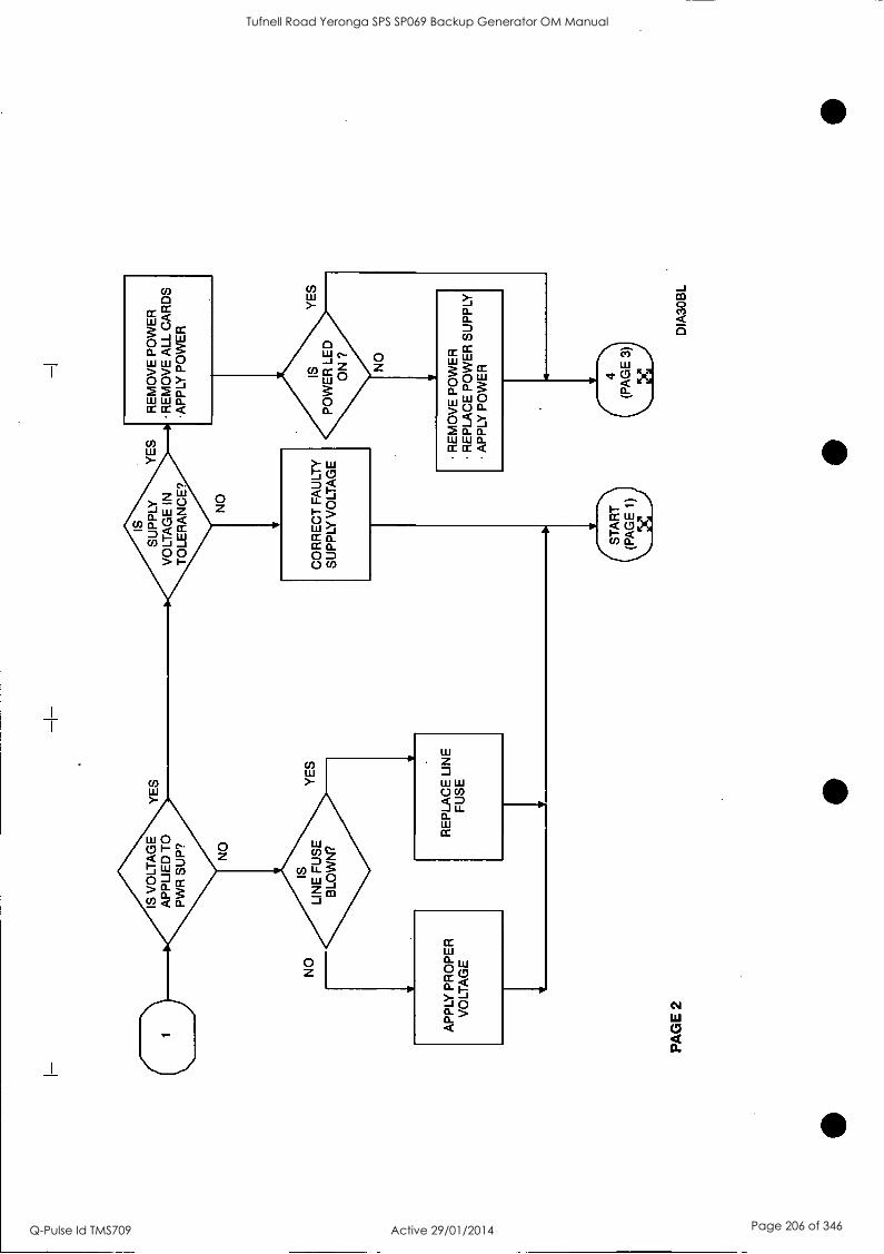
IS V
OLT
AG
E
AP
PLI
ED
TO
P
WR
SU
P?
YE
S
IS
SU
PP
LY
VO
LTA
GE
IN
T
OLE
RA
NC
E?
YE
S
RE
MO
VE
PO
WE
R
RE
MO
VE
ALL
CA
RD
S
AP
PLY
PO
WE
R
NO
IS
LI
NE
FU
SE
B
LOW
N?
CO
RR
EC
T F
AU
LTY
S
UP
PLY
VO
LTA
GE
IS
PO
WE
R L
ED
O
N ?
NO
YE
S
AP
PLY
PR
OP
ER
V
OLT
AG
E
RE
PLA
CE
LIN
E
FU
SE
R
EM
OV
E P
OW
ER
R
EP
LAC
E P
OW
ER
SU
PP
LY
AP
PLY
PO
WE
R
PA
GE
2
(ST
AR
T
(PA
GE
1)
X
(4
(PA
GE
3)
DIA
3OB
L
Tufnell Road Yeronga SPS SP069 Backup Generator OM Manual
Q-Pulse Id TMS709 Active 29/01/2014 Page 206 of 346

-I-
C4 )
RE
MO
VE
PO
WE
R
INS
TA
LL N
EX
T C
AR
D
AP
PLY
PO
WE
R
IS
PO
WE
R L
ED
O
N?
RE
MO
VE
PO
WE
R
RE
PLA
CE
FA
ULT
Y
MO
DU
LE
AP
PLY
PO
WE
R
IS
PO
WE
R L
ED
O
N?
YE
S
YE
S
NO
AR
E A
LL
MO
DU
LES
N
ST
ALL
ED
?
YE
S
RE
MO
VE
PO
WE
R
RE
PLA
CE
PO
WE
R S
UP
PLY
) P
AG
E 1
)
ST
AR
T
PA
GE
3
( D
IA3O
CL
Tufnell Road Yeronga SPS SP069 Backup Generator OM Manual
Q-Pulse Id TMS709 Active 29/01/2014 Page 207 of 346

( 3
CA
N C
PU
C
OM
MU
NIC
AT
W
ITH
LM
90?
YE
S
NO
P(P
AG
E
X
8
CP
U I
N
ST
OP
/FLT
OR
S
TO
P/H
ALT
NO
C
ON
FIG
S
HO
W P
WR
P
IN
ST
OP
YE
S
CO
NS
IDE
R
CH
AN
GIN
G
CO
NF
IG T
O
PO
WE
R U
P I
N R
UN
M
OD
E.
US
E L
M90
OR
HH
P
TO
PLA
CE
PLC
IN
R
UN
MO
DE
.
IS F
AU
LT
SY
S C
ON
FIG
IS
MA
TC
H9
YE
S
US
E L
M90
OR
HH
P
TO
CLE
AR
PLC
&
I/O F
AU
LT T
AB
LES
IS R
UN
LE
D
ON
?
NO
YE
S
IS S
YS
TE
M
OP
ER
AT
IN
OK
?
((P
AG
E 7
) X
5
PA
GE
4
PR
OB
LEM
S
OLV
ED
!
DIA
3OD
L
(PA
GE
1)
X )
S
TA
RT
Tufnell Road Yeronga SPS SP069 Backup Generator OM Manual
Q-Pulse Id TMS709 Active 29/01/2014 Page 208 of 346

( 6
PA
GE
5
331/
341:
R
EM
OV
E P
OW
ER
R
EM
OV
E C
PU
R
EM
OV
E &
RE
PLA
CE
SY
ST
EM
PR
OM
R
EP
LAC
E C
PU
A
PP
LY P
OW
ER
iST
AR
T"
(PA
GE
il))
X
*CO
LD S
TA
RT
DE
LET
ES
TH
E C
ON
TE
NT
S
OF
TH
E C
PU
'S M
EM
OR
Y A
ND
R
ES
TO
RE
S C
OM
MU
NIC
AT
ION
P
AR
AM
ET
ER
S (
BA
UD
RA
TE
, P
AR
ITY
,
ET
C.)
TO
TH
EIR
DE
FA
ULT
VA
LUE
S.
311/
313/
321/
323.
R
EM
OV
E P
OW
ER
R
EM
OV
E A
LL C
AR
DS
& B
AC
K P
LAN
E C
OV
ER
S
HO
RT
SU
PE
R C
AP
(S
EE
NO
TE
4)
RE
PLA
CE
ALL
CA
RD
S &
BA
CK
PLA
NE
CO
VE
R
AP
PLY
PO
WE
R
(ST
AR
T
PA
GE
1) )
DIA
30E
L
Tufnell Road Yeronga SPS SP069 Backup Generator OM Manual
Q-Pulse Id TMS709 Active 29/01/2014 Page 209 of 346

RA
CK
GN
D
EQ
UA
L P
RO
GR
AM
ME
G
ND
?
NO
V
ER
IFY
RA
CK
AN
D
PR
OG
RA
MM
ER
G
RO
UN
D
AR
E T
HE
SA
ME
.
RE
MO
VE
PO
WE
R F
RO
M C
PU
A
PP
LY P
OW
ER
TO
CP
U
CA
N C
PU
C
OM
MU
NIC
AT
IT
H L
M90
?
NO
YE
S
CH
EC
K S
ER
IAL
PO
RT
SE
TT
ING
S.
CH
EC
K C
AB
LE C
ON
NE
CT
ION
S F
RO
M P
C T
O C
PU
. -C
HE
CK
CO
NV
ER
TE
R IF
US
ING
SE
RIA
L LO
GIC
MA
ST
ER
90-
30
EN
SU
RE
PC
WIL
L W
OR
K W
ITH
AN
OT
HE
R 9
0/30
CP
L R
EM
OV
E A
NY
MO
US
E D
RIV
ER
OR
CO
NF
LIC
TIN
G
TE
RM
INA
TE
-AN
D-S
TA
Y-R
ES
IDE
NT
PR
OG
RA
M.
VE
RIF
Y C
PU
WIL
L W
OR
K W
ITH
AN
OT
HE
R P
C.
YE
S
CA
N C
PU
C
OM
MU
NIC
AT
E
WIT
H L
M90
?
(PA
1)
) S
TA
RT
PA
GE
6
NO
(PA
GE
5)
DIA
30F
L
Tufnell Road Yeronga SPS SP069 Backup Generator OM Manual
Q-Pulse Id TMS709 Active 29/01/2014 Page 210 of 346

-I-
-I
( 5
) T
HE
RA
CK
AN
D S
LOT
OF
TH
E
MIS
MA
TC
HE
D M
OD
ULE
AR
E G
IVE
N
IN T
HE
FA
ULT
TA
BLE
AS
A
DE
CIM
AL
NU
MB
ER
(E
G,
0.1,
1.3
, E
TC
.) A
T T
HE
FA
R L
EF
T S
IDE
OF
T
HE
TA
BLE
.
YE
S
SE
LEC
T L
M90
CO
NF
IG
SE
LEC
T I
/O C
ON
FIG
PA
GE
7
EX
IT I
/O C
ON
FIG
S
ELE
CT
& C
LEA
R P
LC F
AU
LT T
AB
LE
SE
LEC
T &
CLE
AR
I/O
FA
ULT
TA
BLE
. S
ELE
CT
UT
ILIT
IES
S
TO
RE
CO
NF
IGU
RA
TIO
N T
O P
LC
CH
AN
GE
LM
90
CO
NF
IG O
R
HA
RD
WA
RE
SO
B
OT
H A
RE
TH
E
SA
ME
.
YE
S
lo,
(ST
AR
T
II.
(PA
GE
1) 1
NO
US
E L
M90
OR
HH
P
TO
PLA
CE
PLC
IN
R
UN
MO
DE
.
RE
PLA
CE
M
ISM
AT
CH
ING
B
OA
RD
DIA
3OG
L
Tufnell Road Yeronga SPS SP069 Backup Generator OM Manual
Q-Pulse Id TMS709 Active 29/01/2014 Page 211 of 346

VE
RIF
Y:
ALL
RA
CK
S A
RE
PR
OP
ER
LY
GR
OU
ND
ED
A
LL L
OA
DS
AR
E P
RO
PE
RLY
S
UR
PR
ES
SE
D
LAS
T R
AC
K IS
PR
OP
ER
LY
TE
RM
INA
TE
D
CA
BLE
S D
O N
OT
EX
CE
ED
MA
Y
LEN
GT
H (
SE
E N
OT
E 6
)
YE
SE
LEC
T U
TIL
ITIE
S IN
LM
90
ST
OP
PLC
S
TO
RE
CO
NF
IGU
RA
TIO
N T
O P
LC
ST
AR
T P
LC
US
E L
M90
OR
HH
P
TO
PLA
CE
PLC
IN
R
UN
MO
DE
.
YE
S
PA
GE
8
NO
VE
RIF
Y:
INP
UT
S A
PP
EA
R I
N R
EF
TA
BLE
S
FO
RC
ED
OU
TP
UT
S E
NE
RG
IZE
F
IELD
DE
VIC
ES
P
RO
GR
AM
LO
GIC
NO
((P
AG
E 1
) X
S
TA
RT
DIA
3OH
L
Tufnell Road Yeronga SPS SP069 Backup Generator OM Manual
Q-Pulse Id TMS709 Active 29/01/2014 Page 212 of 346

I- (
7
) R
EM
OV
E P
OW
ER
R
EP
LAC
E C
PU
A
PP
LY P
OW
ER
PA
GE
9
-I
IS P
OW
ER
LE
D O
N?
YE
S
IS O
K L
ED
T
EA
DY
ON
? Y
ES
C
AN
CP
U
CO
MM
UN
ICA
T
WIT
H L
M90
?
YE
S
NO
(PA
GE
2)
X I
* R
EM
OV
E A
LL M
OD
ULE
S E
XC
EP
T
PO
WE
R S
UP
PLY
AN
D 3
31/3
41 C
PU
RE
MO
VE
PO
WE
R
RE
MO
VE
MO
DU
LES
F
RO
M R
AC
K*
AP
PLY
PO
WE
R
IS O
K L
ED
S
TE
AD
Y O
N
CA
N C
PU
C
OM
MU
NIC
AT
W
ITH
LM
90?
NO
11
(PA
GE
10)
X
/ (S
TA
RT
(P
AG
E)
X
DIA
30JL
Tufnell Road Yeronga SPS SP069 Backup Generator OM Manual
Q-Pulse Id TMS709 Active 29/01/2014 Page 213 of 346

RE
MO
VE
PO
WE
R
RE
PLA
CE
BA
CK
PLA
NE
R
EP
LAC
E P
OW
ER
SU
PP
LY
RE
PLA
CE
331
/341
CP
U
AP
PLY
PO
WE
R
PA
GE
10
(ST
AR
) (P
AG
E 1
) X
YO
UR
PR
OB
LEM
IS
BE
YO
ND
TH
E S
CO
PE
OF
T
HIS
TR
OU
BLE
SH
OO
TIN
G G
UID
E.
CA
LL T
HE
G
E F
AN
UC
HO
TLI
NE
OR
YO
UR
GE
FA
NU
C
DIS
TR
IBU
TO
R F
OR
AS
SIS
TA
NC
E.
DIA
3OK
L
Tufnell Road Yeronga SPS SP069 Backup Generator OM Manual
Q-Pulse Id TMS709 Active 29/01/2014 Page 214 of 346

EQUV ESTABLISHED 1981
DIESEL STANDBY GENERATOR
LOCAL CONTROL PANEL
FUNCTIONAL DESCRIPTION
FOR
Brisbane City Council
19th May 2003
Tufnell Road Yeronga SPS SP069 Backup Generator OM Manual
Q-Pulse Id TMS709 Active 29/01/2014 Page 215 of 346

ABBREVIATIONS
G1 Generator 1 Diesel
a
Tufnell Road Yeronga SPS SP069 Backup Generator OM Manual
Q-Pulse Id TMS709 Active 29/01/2014 Page 216 of 346

1. GENERAL
The PLC for the above operation is a GE Fanuc IC693CPU350. This program has been designed for the use on G1. The operation below controls G1
1.2. A mode selector switch selects how G1 shall operate :
1.2.1. Off
1.2.2. Manual Mode
1.2.3. Test Mode.
1.2.4. Automatic Mode.
2. MANUAL MODE
2.1. To operate G1 in MANUAL Mode.
2.2. Select this operation by turning the AUTO - TEST - MAN- OFF selector switch to the MANUAL position.
2.3. Press the MANUAL START push button to start the generator.
2.4. The generator will begin to crank.
2.4.1. If it fails to start within the 10 seconds, the starter motor is stopped and a delay of 10 seconds before it will attempt to restart.
2.4.2. The generator set is allowed 3 attempts to start.
2.4.3. If it fails to start on the third attempt, the generator is locked out on FAIL TO START Alarm.
2.4.4. When the generator starts, the starter motor is stopped by a stop cranking input which measures the speed of the generator.
2.4.5. Once the generator has started, there is a 10 second time delay for the oil pressure to stabilise.
2.4.6. If the oil pressure is not up to pressure after the 10 second time delay, the generator shall shut down on LOW OIL PRESS Alarm.
2.4.7. Once the generator is running there is a 5 second warm up time before it is ready to accept load.
Tufnell Road Yeronga SPS SP069 Backup Generator OM Manual
Q-Pulse Id TMS709 Active 29/01/2014 Page 217 of 346

2.5. To Manual Transfer to Generator in the MANUAL Mode.
2.5.1. Start the generator and wait for the generator to run up to speed and voltage and ready to accept load.
2.5.2. Press the MANUAL TRANSFER TO GEN push button.
2.5.3. The MAINS ATS shall Open.
2.5.4. After a 30 second delay the GEN ATS shall Close.
2.5.5. If the MAINS ATS fails to Open.
2.5.5.1. After a 5 second delay an Alarm shall be generated and the MAINS CONNECTED indicator shall flash to indicate the Alarm.
2.5.5.2. The system shall return back to MAINS ATS operation.
2.5.6. If the GEN ATS fails to Close.
2.5.6.1. After a 5 second delay an Alarm shall be generated and the GENERATOR CONNECTED indicator shall flash to indicate the Alarm.
2.5.6.2. The system shall return back to MAINS ATS operation.
2.6. To Manual Transfer to Mains in the MANUAL Mode.
2.6.1. The GENERATOR ATS is Closed.
2.6.2. Press the MAN TRANSFER TO MAINS push button.
2.6.3. The GEN ATS shall Open.
2.6.4. After a 30 second delay the MAINS ATS shall Close.
2.6.5. If the GEN ATS fails to Open.
2.6.5.1. After a 5 second delay an Alarm shall be generated and the GENERATOR CONNECTED indicator shall flash to indicate the Alarm.
2.6.5.2. The system shall return back to GEN ATS operation.
2.6.6. If the MAINS ATS fails to Close.
Tufnell Road Yeronga SPS SP069 Backup Generator OM Manual
Q-Pulse Id TMS709 Active 29/01/2014 Page 218 of 346

2.6.6.1. After a 5 second delay an Alarm shall be generated and the MAINS CONNECTED indicator shall flash to indicate the Alarm.
2.6.6.2. The system shall return back to GEN ATS operation.
2.7. To stop the generator in the MANUAL Mode.
2.7.1. When the generator is running, it may be stopped by pressing the MANUAL STOP push button.
2.7.2. If the generator is still GEN ATS operation. The MANUAL TRANSFER TO MAINS is initiated.
2.7.3. When the GEN ATS is Open, the generator will enter the cool down time of 1 second.
2.7.4. After the cool down time, the generator will shut down.
2.7.5. Once the generator has shut down there is a 15 second delay before it may be restarted. This is to ensure the engine has mechanically stopped.
Tufnell Road Yeronga SPS SP069 Backup Generator OM Manual
Q-Pulse Id TMS709 Active 29/01/2014 Page 219 of 346

3. NON-PERMANENT SITE, MANUAL MODE
3.1. To operate G1 in a Non-Permanent Site Location in MANUAL Mode.
3.2. Connect the generator cables to the site generator CB ensuring the site generator CB is OFF. See BCC procedures.
3.3. A plug with shorting links is required to be installed. It is required to be plugged into the 27 Pin Station Plug.
3.3.1. Pins 11 and 12 are required to be connected. This is to indicate that the Mains ATS is Closed. If they are not connected a MAINS ATS Alarm shall be indicated.
3.4. Select from the AUTO - TEST - MAN- OFF selector switch to the MANUAL position.
3.5. Press the MANUAL START push button to start the generator.
3.6. The generator will begin to crank.
3.6.1. If it fails to start within the 10 seconds, the starter motor is stopped and a delay of 10 seconds before it will attempt to restart.
3.6.2. The generator set is allowed 3 attempts to start.
3.6.3. If it fails to start on the third attempt, the generator is locked out on FAIL TO START Alarm.
3.6.4. When the generator starts, the starter motor is stopped by a stop cranking input which measures the speed of the generator.
3.6.5. Once the generator has started, there is a 10 second time delay for the oil pressure to stabilise.
3.6.6. If the oil pressure is not up to pressure after the 10 second time delay, the generator shall shut down on LOW OIL PRESS Alarm.
3.6.7. Once the generator is running there is a 5 second warm up time before it is ready to accept load.
3.7. To connect the generator to the site load.
3.7.1. Manually switch over to the generator supply via the site CB's. See BCC procedures.
3.7.2. Do not use the MANUAL TRANSFER TO GEN or the MAN TRANSFER TO MAINS push buttons.
Tufnell Road Yeronga SPS SP069 Backup Generator OM Manual
Q-Pulse Id TMS709 Active 29/01/2014 Page 220 of 346

3.8. To disconnect the generator from the site load.
3.8.1. Manually switch over to the mains supply via the site CB's. See BCC procedures.
3.8.2. Do not use the MANUAL TRANSFER TO GEN or the MAN TRANSFER TO MAINS push buttons.
3.9. To stop the generator in the MANUAL Mode.
3.9.1. When the generator is running, it may be stopped by pressing the MANUAL STOP push button.
3.9.2. The generator will enter the cool down time of 1 second.
3.9.3. After the cool down time, the generator will shut down.
3.9.4. Once the generator has shut down there is a 15 second delay before it may be restarted. This is to ensure the engine has mechanically stopped.
Tufnell Road Yeronga SPS SP069 Backup Generator OM Manual
Q-Pulse Id TMS709 Active 29/01/2014 Page 221 of 346

4. TEST OPERATION
4.1. To operate the generator in the TEST Mode.
4.2. Select this operation by turning the AUTO - TEST - MAN- OFF selector switch to the TEST position.
4.3. If the selector is changed to MAN while the generator is operating on TEST, the system shall change to MANUAL TRANSFER TO GEN.
4.4. The generator shall begin to crank.
4.4.1. If it fails to start within the 10 seconds, the starter motor is stopped and a delay of 10 seconds before it will attempt to restart.
4.4.2. The generator is allowed 3 attempts to start.
4.4.3. If it fails to start on the third attempt, the generator is faulted on FAIL TO START Alarm.
4.5. When the generator starts, the starter motor is stopped by a stop cranking input which measures the speed of the generator.
4.6. The MAINS ATS shall Open.
4.7. Once the generator has started, there is a 10 second time delay for the oil pressure to stabilise.
4.8. If the oil pressure is not up to pressure after the 10 second time delay, the generator shall shut down on LOW OIL PRESS Alarm.
4.9. Once the generator is running there is a 5 second warm up time before it is ready to accept load.
4.10. After the warm up time has expired and the MAINS ATS has been open for 30 seconds the GEN ATS shall Close.
4.11. If the MAINS ATS fails to Open.
4.11.1. After a 5 second delay an Alarm shall be generated and the MAINS CONNECTED indicator shall flash to indicate the Alarm.
4.11.2. The system shall shut down and return back to MAINS ATS operation.
4.12. If the GEN ATS fails to Close.
Tufnell Road Yeronga SPS SP069 Backup Generator OM Manual
Q-Pulse Id TMS709 Active 29/01/2014 Page 222 of 346

4.12.1. After a 5 second delay an Alarm shall be generated and the GENERATOR CONNECTED indicator shall flash to indicate the Alarm.
4.12.2. The system shall shut down and return back to MAINS ATS operation.
4.13. To stop the generator in the TEST Mode.
4.13.1. Select this operation by turning the AUTO - TEST - MAN- OFF selector switch to the AUTO or OFF position.
4.13.2. The GEN ATS shall Open.
4.13.3. After a 30 second delay the MAINS ATS shall Close.
4.13.4. If the GEN ATS fails to Open.
4.13.4.1.After a 5 second delay an Alarm shall be generated and the GENERATOR CONNECTED indicator shall flash to indicate the Alarm.
4.13.4.2.The system shall return back to GEN ATS operation.
4.13.5. If the MAINS ATS fails to Close.
4.13.5.1.After a 5 second delay an Alarm shall be generated and the MAINS CONNECTED indicator shall flash to indicate the Alarm.
4.13.5.2.The system shall return back to GEN ATS operation.
4.13.6. When the GEN ATS is Open, the generator will enter the cool down time of 5 minutes.
4.13.7. After the cool down time, the generator will shut down.
4.13.8. If a Mains Failure occurs during the cool down period the generator shall transfer back to the GENERATOR ATS without shutting down.
4.13.9. Once the generator has shut down there is a 15 second delay before it may be restarted. This is to ensure the engine has mechanically stopped.
Tufnell Road Yeronga SPS SP069 Backup Generator OM Manual
Q-Pulse Id TMS709 Active 29/01/2014 Page 223 of 346

5. AUTOMATIC OPERATION
5.1. To operate the generator in the AUTO Mode.
5.2. Select this operation by turning the AUTO - TEST - MAN- OFF selector switch to the AUTO position.
5.3. The Phase Failure Relay from the clients switch board shall give a Start Signal for the generators to run.
5.4. The Remote Start Command.
5.4.1. The generator shall begin to crank.
5.4.1.1. If it fails to start within the 10 seconds, the starter motor is stopped and a delay of 10 seconds before it will attempt to restart.
5.4.1.2. The generator is allowed 3 attempts to start.
5.4.1.3. If it fails to start on the third attempt, the generator is faulted on FAIL TO START Alarm.
5.4.2. When the generator starts, the starter motor is stopped by a stop cranking input which measures the speed of the generator.
5.4.3. The MAINS ATS shall Open.
5.4.4. Once the generator has started, there is a 10 second time delay for the oil pressure to stabilise.
5.4.5. If the oil pressure is not up to pressure after the 10 second time delay, the generator shall shut down on LOW OIL PRESS Alarm.
5.4.6. Once the generator is running there is a 5 second warm up time before it is ready to accept load.
5.4.7. After the warm up time has expired and the MAINS ATS has been open for 30 seconds the GEN ATS shall Close.
5.4.8. If the MAINS ATS fails to Open.
5.4.8.1. After a 5 second delay an Alarm shall be generated and the MAINS CONNECTED indicator shall flash to indicate the Alarm.
Tufnell Road Yeronga SPS SP069 Backup Generator OM Manual
Q-Pulse Id TMS709 Active 29/01/2014 Page 224 of 346

5.4.8.2. The system shall shut down and return back to MAINS ATS operation.
5.4.9. If the GEN ATS fails to Close.
5.4.9.1. After a 5 second delay an Alarm shall be generated and the GENERATOR CONNECTED indicator shall flash to indicate the Alarm.
5.4.9.2. The system shall shut down and return back to MAINS ATS operation.
5.5. To stop the generator in the AUTO Mode.
5.5.1. The Phase Failure Relay from the clients switch board shall give a Stop Signal for the generators to run.
5.5.2. The Remote Stop Command.
5.5.3. There is a 2 minute proving time for the Phase Failure Relay.
5.5.4. After the 2 minute proving time the GEN ATS shall Open.
5.5.5. After a 30 second delay the MAINS ATS shall Close.
5.5.6. If the GEN ATS fails to Open.
5.5.6.1. After a 5 second delay an Alarm shall be generated and the GENERATOR CONNECTED indicator shall flash to indicate the Alarm.
5.5.6.2. The system shall return back to GEN ATS operation.
5.5.7. If the MAINS ATS fails to Close.
5.5.7.1. After a 5 second delay an Alarm shall be generated and the MAINS CONNECTED indicator shall flash to indicate the Alarm.
5.5.7.2. The system shall return back to GEN ATS operation.
5.5.8. When the GEN ATS is Open, the generator will enter the cool down time of 5 minutes.
5.5.9. After the cool down time, the generator will shut down.
5.5.10. If a Mains Failure occurs during the cool down period the generator shall transfer back to the GENERATOR ATS without shutting down.
Tufnell Road Yeronga SPS SP069 Backup Generator OM Manual
Q-Pulse Id TMS709 Active 29/01/2014 Page 225 of 346

5.5.11. Once the generator has shut down there is a 15 second delay before it may be restarted. This is to ensure the engine has mechanically stopped.
Tufnell Road Yeronga SPS SP069 Backup Generator OM Manual
Q-Pulse Id TMS709 Active 29/01/2014 Page 226 of 346

6. FAULT OPERATION
6.1. Emergency Stop Operation.
6.1.1. Operation of the Emergency Stop push button immediately shuts down the generator and Opens the Generator CB. The Emergency Stop is latched, and requires manual resetting to release the Emergency Stop push button.
6.1.2. After the Emergency Stop push button is released, a fault reset will need to be initiated to reset the PLC.
6.2. HIGH HIGH Alarm Operation.
6.2.1. The Generator CB is Opened immediately.
6.2.2. The generator is shut down immediately.
6.2.3. The following alarms will initiate a HIGH HIGH Alarm condition :-
6.2.3.1. Emergency Stop Fault
6.2.3.2. MEN Fault
6.2.3.3. Low Oil Pressure Shutdown Fault, 10 Seconds Startup Delay
6.2.3.4. High Engine Temperature Shutdown Fault, 30 Second Startup Delay
6.2.3.5. Low Radiator Level Fault, 5 Second Delay
6.2.3.6. Over Speed Fault
6.3. HIGH Alarm Operation
6.3.1. The Generator CB is Opened immediately.
6.3.2. Once the generator circuit breaker is opened, the generator will run through its normal cool down time and shut down.
6.3.3. The following alarms will initiate a HIGH Alarm condition: -
6.3.3.1. Generator Under Speed Fault, 5 Second Delay
6.3.3.2. Alternator Under Voltage Fault, 5 Second Delay
6.3.3.3. Alternator Over Voltage Fault, 5 Second Delay
Tufnell Road Yeronga SPS SP069 Backup Generator OM Manual
Q-Pulse Id TMS709 Active 29/01/2014 Page 227 of 346

6.3.3.4. Generator CB Tripped Fault
6.3.3.5. Alternator High Temperature Fault, 30 Second Startup Delay
6.4. MEDIUM Alarm Operation.
6.4.1. A Normal Shutdown shall be Initiated.
6.4.2. If the GEN ATS does not Open then the Generator CB is Opened.
6.4.3. The following alarms will initiate a MEDIUM Alarm condition :-
6.4.3.1. Fuel Empty Level Fault, 5 Second Delay
6.4.3.2. Fail To Start Fault, 3 Attempts
6.5. LOW Alarm Operation.
6.5.1. A Warning has occurred on the generator. The generator will not shut down.
6.5.2. The following alarms will initiate a LOW Alarm condition :-
6.5.2.1. Low Oil Pressure Warning Alarm, 10 Seconds Startup Delay
6.5.2.2. High Engine Temperature Warning Alarm, 30 Second Startup Delay
6.5.2.3. Fuel Low Level Alarm, 5 Second Delay
6.5.2.4. Battery Charger AC Supply Failed Alarm, 60 Second Delay
6.5.2.5. Control Battery Low Volts Alarm, 30 Second Delay
6.5.2.6. Start Battery Low Volts Alarm, 60 Second Delay
S
Tufnell Road Yeronga SPS SP069 Backup Generator OM Manual
Q-Pulse Id TMS709 Active 29/01/2014 Page 228 of 346

11/06/04 3:02 BCC 4000 4 Page: A
Table of Contents Overview
1 Main Rack: Base 10 Slot (IC693CHS391) 1
Detailed View 2 IC693PWR331 Power Supply 24 VDC 30W 2
Power Consutption 2 Settings '2
IC693CPU350 Series 90-30 CPU Model 350 2 Settings 2 Scan -
Memory 2 Power Consumption 3
IC693CMM311 Communications Coprocessor 3 Settings 3 Port 1. 3 Port 2 3 Tower Consumption 3
IC693MDL645 16 Circuit Input 24 VDC Positive / Negative Logic 3 -Settings - - 3 Wiring
3 Power Consumption 3
IC693MDL645 16 Circuit Input 24 VDC Positive / Negative Logic 4
Settings 4
Wiring - 4
Power Consumption 4
IC693MDL645 16'Circuit Input 24 VDC Positive / Negative Logic 4
Settings 4
Wiring 4
Power ConsuMption 4 IC693MDL940 16 Circuit Output Relay 2A 4
Settings 4
Wiring 4
Power Consumption 4
IC693MDL940 16 Circuit Output Relay 2A 5 Settings
5 Wiring 5 Power Consumption 5
IC693MDL940 16 Circuit Output Relay 2A Settings
5
5 Wiring
5 Power Consumption 5
Reference Details - 6 %I References %Q References
6
Table of Contents GE Fantle Hardware Configuration Series 90-30
Tufnell Road Yeronga SPS SP069 Backup Generator OM Manual
Q-Pulse Id TMS709 Active 29/01/2014 Page 229 of 346

11/06/04 3:02 BCC 4000 4
Main Rack: Base 10 Slot (IC693CHS391)
Overview
Page: 1
GE Fanuc Hardware Configuration Series 90-30
Tufnell Road Yeronga SPS SP069 Backup Generator OM Manual
Q-Pulse Id TMS709 Active 29/01/2014 Page 230 of 346

11/06/04 3:02 BCC 4000 4 Page: 2
Main Rack: Slot 0 IC693PWR331 Power Supply 24 VDC 30W Power Consumption
Voltages / Supplied +5VDC (Watts) 30
+24VDC Relay Power (Watts) 15 +24VDC Isolated (Watts) 20
Total System: 30
Settings Parameters /Values Hand Held Programmer: No Converter: 0
Main Rack: Slot 1 IC693CPU350 Series 90-30 CPU Model 350 Settings
Parammetms/Vatues I/O Scan-Stop: No Power Up Mode: Run Logic / Configuration. From: RAM Registers: RAM Passwords: Disabled Checksum Words: 8
Data Rate (bps): 19200 Parity: Odd Stop Bits: 1
Modem Turnaround Time (.01 Sec / Count): 0
Idle Time (Sec): 10 Timer Faults: Disabled SNP ID: Key Switch Run/Stop: Enabled Memory Protect: Disabled Ignore Fatal Faults: Disabled
Scan Parameters / Values Sweep. Mode: Normal Sweep Timer (mSec): N/A
Memory Parameters / Values %I Discrete Input: 2048 %Q Discrete Output: 2048 %S System Use: 128 %M Internal Discrete: 4096 %T Temporary Status: 256 %G Genius® Global: 1280 %AI Analog Input: 2048 %AQ Analog Output: 512 %R Register Memory: 9999
Detailed View GE Fanuc Hardware Configuration Series 90-30
Tufnell Road Yeronga SPS SP069 Backup Generator OM Manual
Q-Pulse Id TMS709 Active 29/01/2014 Page 231 of 346

11/06/04 3:02 BCC 4000 4
Power Consumption Parameters / Values +5VDC (Watts) 3.35 +24VDC Relay Power (Watts) 0
+24VDC Isolated (Watts) 0
Main Rack: Slot 2 1C693CM1V1311 Communications Coprocessor Settings
Parameters / Values Configuration Mode: RTU Only
Port 1 Parameters / Values RTU Enable: Yes Data Rate (bps): 9600 Flow Control: None Parity: None Station Address: 1
Port 2 Pa rameters / Values RTU Enable: Yes Interface: RS485 Data Rate (bps): 9600 Flow Control: None Parity: None Station Address: 1
Power Consumption Parameters / Values +5VDC (Watts) 2.00 +24VDC Relay Power (Watts) 0
+24VDC Isolated (Watts) 0
Main Rack: Slot 3 IC693MDL645 16 Circuit Input 24 VDC Positive / Negative Logic Settings
Parameters / Values Reference Address: %I00001 Length: 16
Wiring Terminal / Wiring Information From Terminal 1 to Terminal 20 : No wiring information.
Power Consumption Parameters / Values +5VDC (Watts) 0.40 +24VDC Relay Power (Watts) 0
Detailed View GE Fanuc Hardware Configuration
Page:
Series 90-30
41111
Tufnell Road Yeronga SPS SP069 Backup Generator OM Manual
Q-Pulse Id TMS709 Active 29/01/2014 Page 232 of 346

11/06/04 3:02
+24VDC Isolated (Watts) 0.6
BCC 4000 4 Page: 4
Main Rack: Slot 4 IC693MDL645 16 Circuit Input 24 VDC Positive / Negative Logic Settings
Parameters / Values Reference Address: $100017 Length: 16
Wiring Terminal / Wiring Information From Terminal 1 to Terminal 20 : No wiring information.
Power Consumption Parameters / Values +5VDC (Watts) 0.40 +24VDC Relay Power (Watts) 0
+24VDC Isolated (Watts) 0.6
Main Rack: Slot 5 IC693MDL645 16 Circuit Input 24 VDC Positive / Negative Logic Settings
Parameters / Values Reference Address: $100033 Length: 16
Wiring Terminal / Wiring Information From Terminal 1 to Terminal 20 : No Wiring information.
Power Consumption Parameters / Values +5VDC (Watts) 0.40 +24VDC Relay Power (Watts) 0
+24VDC Isolated (Watts) 0.6
Main Rack: Slot 7 IC693MDL940 16 Circuit Output Relay 2A Settings
Parameters / Values Reference Address: $(200001 Length: 16
Wiring Terminal / Wiring Information From Terminal 1 to Terminal 20 : No wiring information.
Power Consumption Detailed View GE Fanuc Hardware Configuration Series 90-30
Tufnell Road Yeronga SPS SP069 Backup Generator OM Manual
Q-Pulse Id TMS709 Active 29/01/2014 Page 233 of 346

11/06/04 3:02
Parameters / Values +5VDC (Watts) 0.04
+24VDC Relay Power (Watts)
3.24
+24VDC Isolated (Watts) 0
BCC 4000 4 Page: 5
Main Rack: Slot 8
10693MT)1.940 16 Circuit Output Relay 2A
Settings Parameters / Values Reference
Address: %Q00017
Length: 16
Wiring Terminal / Wiring Information
From Terminal 1 to Terminal
20 : No wiring information.
Power Consumption Parameters / Values +5VDC (Watts) 0.04
+24VDC Relay Power (Watts) 3.24
+24VDC Isolated (Watts) 0
Main Rack: Slot 9
IC693MD1,940 16 Circuit Output Relay 2A
Settings Parameters / Values Reference
Address: %Q00033
Length: 16
Wiring Terminal / Wiring Information
From Terminal 1 to Terminal
20 : No wiring information.
Power Consumption Parameters / Values +5VDC (Watts)
0.04
+24VDC Relay Power (Watts)
3.24
+24VDC Isolated (Watts) 0
Detailed View GE Fantle Hardware Configuration
Series 90
Tufnell Road Yeronga SPS SP069 Backup Generator OM Manual
Q-Pulse Id TMS709 Active 29/01/2014 Page 234 of 346

11/06/04 3:02 BCC 4000 4
%I References Overlap Start End
1 16
17 32
33 48
Total %I: 48
%Q References Overlap Start End
1 16
17 32
33 48
Total %Q: 48
Reference Details
Addr (0.3)
(0.4)
(0.5)
Highest
Add r (0.7) (0.8)
(0.9)
Highest
Mem Type Consumed Consumed Consumed
Reference: 48
Mem Type Produced Produced Produced
Reference: 48
Cat Num IC693MDL645 IC693MDL645 IC693MDL645
Cat Num IC693MDL940 IC693MDL940 IC693MDL940
GE Fanuc Hardware Configuration
Page: 6
Series 9 0-3 0
Tufnell Road Yeronga SPS SP069 Backup Generator OM Manual
Q-Pulse Id TMS709 Active 29/01/2014 Page 235 of 346

Name Type Len Address Description Stored Val Scope SEL_AUTO BIT 1 %100001 Selector Switch Auto Globa SEL_TEST BIT 1 %I00002 Selector Switch Test Globa SEL_MAN BIT 1 %100003 Selector Switch Manual Globa EM_STOP_PB BIT 1 %I00004 Emergency Stop PB Globa 'LAMP. TEST_PB BIT 1 %I00005 Lamp Test PB Globa ALM_RESET_PB BIT 1 %100006 Alarm Reset PB Globa AL M_MUTE_PB BIT 1 %100007 Alarm Mute PB Globa MAN_S'TR_PB BIT 1 %I00008 Manaul Start PB Globa MAN STP PB BIT 1 .%100009 Manual Stop PB Globa MAN-TRFNAINS_PB BIT %100010 Manual Transfer to Mains PB Globa MAN_TRF_GEN_PB BIT 1 %I00011 Manual Transfer to Generator Globa PB
SPD_STP_CRK BIT 1 %I00017 Crank Cutout Relay Globa SPD_UNDER BIT 1 %I00018 Under Speed Relay Globa SPD_OVER BIT 1 %100019 Over Speed Relay Globa VOLTS. UNDER BIT 1 %I00020 Under Voltage Relay Globa VOLTS_OVER BIT 1 %I00021 Over Voltage Relay Globa ALT TEMP BIT 1 %I00022 Alternator High Temperature Globa Relay
GEN_CB TRIP BIT 1 %100023 Generator CB Tripped Globa MEN FLT BIT 1 %100024 MEN Fault Relay Globa BAT=CHG_AC BIT 1 %100025 Battery Charger AC Relay Globa -BAT_CONT LOW V BIT 1 %100026 Control Battery Charger Low Globa Voltage
BAT_STR_LOW_V BIT 1 %I00027 Start Battery Charger Low Globa Voltage
MAINS_FAILED BIT 1 %100033 BCC Mains Failed Globa MAINS ATS_CLS BIT 1 %100034 BCC Mains ATS Closed Globa GEN_ATS_CLS BIT 1 %100035 BCC Generator ATS Closed Globa .REM STR BIT 1 %100036 BCC Remote Start Globa REM-STP BIT 1 %100037 BCC Remote Stop Globa 01113_LOW_SD BIT 1 %100041 Low Oil Pressure Shutdown Globa OILP_LOW_W BIT 1 %100042 Low Oil Pressure Warning Globa ENG T HI SD BIT 1 %I00043 High Engine Temperature Globa Shutdown
ENG T_HI W BIT 1 %100044 High Engine Temperature Globa Warning
RAD WATER_LOW BIT 1 %100045 Low Radiator Water Level Globa FUEL_LEV_LOW BIT 1 %100046 Low Fuel Level Globa FUEL_LEV_EMPTY BIT 1 %100047 Fuel Empty Globa CAN DOORS_OPEN BIT 1 %I00048 Canopy Doors Open Globa STEP- 1 BIT 1 %M00001 Step Sequence No.1 Globa STEP 2_E BIT 1 %M00002 Step Sequence No.2 Globa STEP 3 BIT 1 %M00003 Step Sequence No.3 Globa STEP:4 BIT 1 %M00004 Step Sequence No.4 Globa STEP _5 BIT 1 %M00005 Step Sequence No.5 Globa STEP_6 BIT 1 %M00006 Step Sequence No.6 Globa STEP 7 BIT 1 %M00007 Step Sequence No.7 Globa STEP=8 BIT 1 %M00008 Step Sequence No.8 Globa STEP_9 BIT 1 %M00009 Step Sequence No.9 Globa STEP_2_GE BIT 1 %M00022 Step Sequence No.2 GE Globa GEN_OFF BIT 1 %M00101 Generator OFF Globa AUTO TEST_STR BIT 1 %M00102 Auto _Test Start / Stop Globa REMOTE_STR BIT 1 %M00103 Remote Start Globa MAINS_FAIL_STP BIT 1 %M00104 Mains Failed Stop Globa REMOTE_STP BIT 1 %M00105 Remote Stop Globa TEST_STR BIT 1 %M00106 Test Start Globa TEST STP BIT 1 %M00107 Test Stop Globa GEN RUN OFF BIT 1 %M00108 Generator Run Off Globa ENAffLE_CYFFLINE BIT 1 %M00109 Enable Generator to go Globa Offline
HH ALM_OS1 BIT 1 %M00110 High High Alarm One Shot Globa H_ALM_OS1 BIT 1 %M00111 High Alarm One Shot Globa H_ALM_OS2 BIT 1 %M00112 High Alarm One Shot Globa M ALM_OS1 BIT 1 %M00113 Medium Alarm One Shot Globa M_ALM_OS2 BIT 1 %M00114 Medium Alarm One Shot Globa M_ATS ALM_OS1 BIT 1 %M00115 Mains ATS Alarm One Shot Globa M_ATS_ALM_OS2 BIT 1 %M00116 Mains ATS Alarm One Shot Globa MAINS_FAIL_STR BIT 1 %M00117 Mains Fail Start Globa GEN_RUNNING BIT 1 %M00201 Generator Running Globa FA1L_STR TM BIT 1 %M00202 Failed to Start Time Globa FAIL_STR_DLY BIT 1 %M00203 Failed to Start Pulse Delay Globa Program: BCC_4000_4 A:
Ret
R
ovr 6
GLOBAL VARIABI
Tufnell Road Yeronga SPS SP069 Backup Generator OM Manual
Q-Pulse Id TMS709 Active 29/01/2014 Page 236 of 346

Name FAIL_STR_CNT CRK_CUTOUT
ii_STR_DLY
P_DLY FI ST UP_DLY
M_ATS_OPN 1
G ATS CLS
G ATS_OPN_1
MATS_CLS_1 M_ATS_CLS ENB G_ATS_CLCENB HIGH HIGH ALM EM S-"fP_ALM MEN_ALM OILP_SDALM
ENG_T SD_ALM
RAD_WATER_LOW_ALM
SPD_OVER_ALM RAD_WATER_LOW_DLY
OVERDLY GH_ALM
SPD_UNDER_ALM VOLTS_UNDER_ALM
VOLTS_OVER ALM
GEN CB_TRIP_ALM ALT 7-TEMP ALM
SPD UNDER_DLY VOLTS_UNDER_DLY VOLTS_OVER_DLY MEDIUM_ALM FUEL_LEV EMPTY ALM FAIL TO_STR ALM FUEL_LEV_EMPTY_DLY
LOW_ALM OILP WALM
ENGT WALM
SL_LEV_LOW_ALM BAT_CHG_AC_ALM BAT_CONT LOW V ALM
BAT_STR_LOW V_ALM
FUEL_LEV_LOW DLY BAT_CHG_AC_DLY
BAT_CONT_LOW V DLY
BAT_STR_LOW V_DLY
MAINS ATS_OPN_ALM
MAINS_ATS_CLS_ALM
GEN_ATS_OPN ALM
GEN ATS_CLS ALM
NEW_ALM 000401 rOgram: BCC_4000_4
Type BIT BIT BIT
BIT BIT BIT BIT
BIT
BIT BIT BIT BIT BIT BIT BIT
BIT
BIT
BIT BIT
BIT BIT BIT BIT
BIT
BIT BIT
BIT BIT BIT BIT BIT BIT BIT
BIT BIT
BIT
BIT BIT BIT
BIT
BIT BIT
BIT
BIT
BIT
BIT
BIT
BIT
BIT BIT
Len Address Description Stored Val Scope Ret Ovr 1 %M00204 Failed to Start Counter Globa 1 %M00205 Generator Crank Cutout Globa 1 %M00206 Enable Start Delay for Globa
Alarms 1 %M00207 Oil Pressure Alarm Delay Globa 1 %M00208 Startup Alarm Delay Globa 1. %M00209 Mains ATS Open Command Globa
%M00210 Generator ATS Close Globa Command
1 %M00211 Generator ATS Open Globa Command
1 %M00212 Mains ATS Close Command Globa 1 %M00213 Mains ATS Close Enable Globa 1 %M00214 Generator ATS Close Enable Globa 1 %M00300 High High Alarm Globa 1 %M00301 Emergency Stop Alarm Globa 1 %M00302 MEN Alarm Globa 1 %M00303 Low Oil Pressure Shutdown Globa
Alarm 1 %M00304 High Engine Temperature Globa
Shutdown Alarm 1 %M00305 Low Radiator Water Level Globa
Alarm 1 %M00306 Over Speed Alarm Globa 1 %M00315 Radiator Water Level Low Globa
Delay 1 %M00316 Over Speed Delay Timer Globa 1 %M00320 High Alarm Globa 1 %M00321 Under Speed Alarm Globa 1 %M00322 Alternator Voltage Under Globa
Alarm 1 %M00323 Alternator Voltage Over Globa
Alarm 1 %M00324 Generator CB Tripped Alarm Globa 1 %M00325 Alternator High Temperature Globa
Alarm 1 %M00331 Under Speed Alarm Delay Globa 1 %M00332 Under Voltage Alarm Delay Globa 1 %M00333 Over Voltage Alarm Delay Globa 1 %M00340 Medium Alarm Globa 1 %M00341 Fuel Empty Alarm Globa 1 %M00342 Fail to Start Alarm Globa
%M00351 Fuel Level Empty Alarm Globa Delay
1 %M00360 Low Alarm Globa 1 %M00361 Low Oil Pressure Warning Globa
Alarm 1 %M00362 High Engine Temperature Globa
Warning Alarm 1 %M00363 Low Fuel Level Alarm Globa 1 %M00364 Battery Charger AC Alarm Globa 1 %M00365 Control Battery Charger Low Globa
Voltage Alarm 1 %M00366 Start Battery Charger Low Global
Voltage Alarm 1 %M00373 Fuel Level Low Alarm Delay Global R 1 %M00374 Battery Charger AC Failure Global R
Delay 1 %M00375 Control Battery Low Voltage Global R
Delay 1 %M00376 Start Battery Low Voltage Global R
Delay 1 %M00381 Mains ATS Failed to Open Global
Alarm 1 %M00382 Mains ATS Failed to Close Global
Alarm 1 %M00383 Generator ATS Failed to Global
Open Alarm 1 %M00384 Generator ATS Failed to Global
Close Alarm 1 %M00400 New Alarm Global 1 %M00401 "No Description** Global
A: GLOBAL VARIA13I
Tufnell Road Yeronga SPS SP069 Backup Generator OM Manual
Q-Pulse Id TMS709 Active 29/01/2014 Page 237 of 346

Name Type Len Address Description Stored Val Scope Ret %M00402 BIT 1 %M00402 "No Description** Globa R %M00403 BIT 1 %M00403 **No Description" Globa R %M00404 BIT 1 %M00404 "No Description** Globa R %M00405 BIT 1 %M00405 No Description" Globa R %M00406 BIT 1 %M00406 **No Description" Globa R %1v100421 BIT 1 %M00421 **No Description" Globa R %M00422 BIT 1 %M00422 **No Description" Globa R %M00423 BIT %M00424 BIT
1
1
%M00423 %M00424
**No Description" **No Description**
Globa Globa
R R %M00425 BIT
%M00441 BIT 1
1
%M00425 %M00441
**No Description" **No Description**
Globa Globa
R R %M00442 BIT
%M00461 BIT 1
1
%M00442 %M00461
"**No Description" *-*No Description**
Globa Globa
R R %Tv100462 BIT 1 %M00462 '*No Description' Globa R %M00463 BIT 1 %M00463 **No Description" Globa R %1v100464 BIT
-%M00465 .BIT 1
1
%M00464 %M00465
"No Description" **No Description**
Globa Globa
R R %M00466 BIT
%M00481 BIT 1
1
%M00466 %M00481
**No Description" '**No Description**
Globa Globa
R R %M00482 _ BIT
%M00483 BIT 1
1
%M00482 %M00483
"No Description" **No Description**
Globa Globa
R R %M00484 BIT 1 %M00484 "No Description' Globa R AUTOIND BIT 1 %000001 Controls in Auto Indicator Globa TESTIND BIT 1 %000002 Controls in Test Indicator Globa MAN_IND BIT 1 %Q00003 Controls in Manual Indicator Globa REM_STRIND BIT 1 %Q00004 Remote Start Indicator Globa MAINS AVAILIND BIT 1 %000005 Mains Available Indicator Globa MAINSCONIND BIT 1 %Q00006 Mains Connected Indicator Globa GEN_RUNIND BIT 1 %Q00007 Generator Running Indicator Globa GEN_CONIND BIT 1 %000008 Generator Connected Globa
Indicated MAINS _FAILED...IND BIT 1 %000009 Mains Failed Indicator Globa EM_STOP_IND BIT 1 %Q00010 Emergency Stop Indicator Globa MEN_FLT_IND BIT 1 %Q00011 MEN Fault Indicator Globa OIL_P_LOW_SDIND BIT 1 %Q00012 Low Oil Pressure Shutdown Globa
Indicator OIL_P_LOW WIND BIT 1 %Q00013 Low Oil Pressure Warning Globa
Indicator ENG T_HI_SD_IND BIT 1 %Q00014 High Engine Temperature Globa
Shutdown Indicator ENG T_HI WIND BIT 1 %Q00015 High Engine Temperature Globa
Warning Indicator RAD WATER_LOWIND BIT 1 %Q00016 Law Radiator Water Level Globa
Indicator FUEL LEV EMPTY IND BIT 1 %Q00017 Fuel Empty Indicator Globa FUEL_LEV LOWIND BIT 1 %Q00018 Low Fuel Level Indicator Globa SPD_OVEff IND BIT 1 %000019 Over Speed Indicator Globa SPD_UNDER_IND BIT 1 %000020 Under Speed Indicator Globa FAIL TO_STR IND BIT 1 %Q00021 Fail to Start Indicator Globa VOLTS_UNDETUND BIT 1 %Q00022 Alternator Voltage Under Globa
Indicator VOLTS_OVERIND BIT 1 %000023 Alternator Voltage Over Globa
Indicator ALT TEMPIND BIT 1 %000024 Alternator High Temperature Globa
Indicator GEN_CB_TRIPIND BIT 1 %000025 Generator CB Tripped Globa
Indicator BAT_CHG AC IND BIT 1 %000026 Battery Charger AC Indicator Globa BAT CONT LOW V IND BIT 1 %000027 Control Battery Charger Low Globa
Voltage Indicator BAT STR_LOW_V IND BIT 1 %Q00028 Start Battery Charger Low Globa Voltage Indicator
CAN_DOORS_OPEN _IND BIT 1 %Q00029 Canopy Doors Open Globa Indicator
MAINS_ATS_OPN_CMD BIT 1 %Q00033 BCC Mains ATS Open Globa Command
GEN_ATS_CLS_CMD BIT 1 %Ct00034 BCC Generator ATS Close Globa Command
GEN_SD_ALM BIT 1 %Q00035 BCC Generator Shutdown Globa Alarm
GEN_W_ALM BIT 1 %Q00036 BCC Generator Warning Globa Alarm
Program: BCC_4000_4 A:
Ovr
S
GLOBAL VARIABI
Tufnell Road Yeronga SPS SP069 Backup Generator OM Manual
Q-Pulse Id TMS709 Active 29/01/2014 Page 238 of 346

Name FUEL_LOW G EN_RUN GEN_CON IR R
AAR SDAR DOORS_OPEN GEN_AUTO SEQ_CNT MODBUSINPUTS MODBUS_OUTPUTS MODBUS_STATUS_1 MODBUS_STATUS_2 MODBUS_ALARMS %R00100 %R00103 %R00106 %R00109 %R00112 %R00115 %R00118 %R00121 %R00124 %R00127
0
00133 00136
%R00139 %R00200 %R00203 %R00206 %R00209 %R00212 %R00215 %R00218 %R00221 %R00224 %R00227 %R00230 %R00300 %R00303 %R00306 %R00309 %R00312 %R00315 %R00318 %R00321
327 0 00330
%R00333 %R00336 %R00339 FST SCN
LST_SCAN
OMS T_100MS T1S T1 M ALW_ON ALW_OFF PLC BAT
%R00400
1Pgram: BCC_4000_4
Type Len BIT 1
BIT 1
BIT 1
BIT 1
BIT 1
BIT 1
BIT 1
BIT 1
BIT 1
WORD 1
WORD 1
WORD 1
WORD 1
WORD 1
WORD 1
WORD 3 WORD 3 WORD 3 WORD 3 WORD 3 WORD 3 WORD 3 WORD 3 WORD 3 WORD 3 WORD 3 WORD 3 WORD 3 WORD 3 WORD 3 WORD 3 WORD 3 WORD 3 WORD 3 WORD 3 WORD 3 WORD 3 WORD 3 WORD 3 WORD 3 WORD 3 WORD 3 WORD 3 WORD 3 WORD 3 WORD 3 WORD 3 WORD 3 WORD 3 WORD 3 WORD 3 WORD 3 WORD 3 WORD 3 BIT 1
. . Address Description %Q00037 BCC Low Fuel %Q00038 BCC Generator Running %Q00039 BCC Generator Connected %000040 Starter Motor Relay %Q00041 Governor Control Relay %Q00042 Audible Alarm Relay %Q00043 Generator Shunt Trip Relay %000044 BCC Doors Open Alarm %000045 Generator Auto Mode %R00001 Sequence Counter %R00002 Modbus Digital Inputs %R00005 Modbus Digital Outputs %R00008 Modbus Status 1
%R00009 Modbus Status 2 %R00010 Modbus Alarms %R00100 *'No Description** %R00103 **No Description" %R00106 **No Description** %R00109 '"No Description** %R00112 **No Description** %R00115 **No Description** %R00118 **No Description** %R00121 **No Description** %R00124 **No Description** %R00127 **No Description** %R00130 **No Description** %R00133 - **No Description** %R00136 **No Description** %R00139 **No Description** %R00200 **No Description** %R00203 **No Description** %R00206 **No Description** %R00209 **No Description** %R00212 **No Description" %R00215 **No Description** %R00218 **No Description** %R00221 **No Description** %R00224 **No Description** %R00227 **No Description** %R00230 '**No Description" %R00300 **No Description** %R00303 **No Description** %R00306 **No Description** %R00309 **No Description" %R00312 **No Description** %R00315 **No Description" %R00318 **No Description** %R00321 **No Description" %R00324 **No Description** %R00327 "'No Description** %R00330. **No Description** %R00333 **No Description** %R00336 "'No Description" %R00339 *"No Description** %S00001 Set to 1 when the current
sweep is the first sweep Reset from 1 to 0 when the current sweep is the last sweep 0.01 Second Timer Contact 0.1 Second Timer Contact 1 Second Timer Contact 1 Minute Timer Contact Always ON Always OFF Set to indicate a bad battery in the CPU **No Description"
BIT 1 %S00002
BIT 1 %S00003 BIT 1 %S00004 BIT 1 %S00005 BIT 1 %S00006 BIT 1 %S00007 BIT 1 %S00008 BIT 1 %S00014
WORD 1 %R00400
Stored Val Scope Ret Ovr E Globa Globa Globa Globa Globa Globa Globa Globa Globa Globa Globa Globa Globa Globa Globa Globa Globa Globa Globa Globa Globa Globa Globa Globa Globa Globa Globa Globa Globa Globa Globa Globa Globa Globa Globa Globa Globa Globa Globa Globa Globa Globa Globa Globa Globa Globa Globa Globa Globa Globa Globa Globa Globa Globa Globa
Globa
Global Global Global Global Global Global Global
R
R R R R R R R
Global R
A: GLOBAL VARIABL
Tufnell Road Yeronga SPS SP069 Backup Generator OM Manual
Q-Pulse Id TMS709 Active 29/01/2014 Page 239 of 346

Name Type Len Address Description Stored Val Scope Ret Ow E FST_SCN BIT 1 %S00001 Set to 1 when the current sweep is the first sweep
System R
LST_SCN BIT 1 %S00002 Reset from 1 to 0 when the current sweep is the last sweep
System R
T10MS BIT 1 %S00003 0.01 second timer contact System R T100MS BIT 1 %S00004 0.1 second timer contact System R T__S EC BIT 1 %S00005 1.0 second timer contact System R T_MIN BIT 1 %S00006 1.0 minute timer contact System R ALW ON BIT 1 %S00007 Always ON System R ALW OFF BIT 1 %S00008 Always OFF System R SY_FULL BIT 1 %S00009 Set when the PLC fault table
fills up System R
10_FULL BIT 1 %S00010 Set when the I/O fault table fills up
System R.
OVR_PRE BIT 1 %S00011 Set when an override exists in %I, %Q, %M or %G memory
System R
PRG_CHK BIT 1 %S00013 Set when background program check is active
System R
PLC_BAT BIT 1 %S00014 Set to indicate a bad battery in a Release 4 or later CPU
System R
SNPXACT BIT 1 %S00017 SNP-X host is actively attached to the CPU
System R
SNPX_RD BIT 1 %S00018 SNP-X host has read data from the CPU
System R
SNPX_VVT BIT 1 %S00019. SNP-X host has written data to the CPU
System R
RLTN_OK BIT 1 %S00020 Set ON when a relational function using REAL data is success
System R
CONTCON BIT 1 %S00032 Reserved for use by the programming software for cont contact
System R.
PB_SUM BIT 1 %SA0001 Set when PLC checksum does not match app checksum
System R
OV SWP BIT 1 %SA0002 Set when PLC sweep time is longer than user specified sweep time
System R
APL FLT BIT 1 %SA0003 Set when an application fault occurs
System R
CFG_MM BIT 1 %SA0009 Set when a config mismatch is detected during system powerup
System R
HRD_CPU BIT 1 %SA0010 Set when the diagnostics detects a problem with the
System R
CPU hardware LOW BAT BIT 1 %SA0011 Set when a low battery fault
occurs ,
System R
LOS_RCK BIT 1 %SA0012 Set when an expansion rack stops communicating with the
System R
CPU LOS _IOM BIT' 1 %SA0014 Set when an I/O module
stops communicating with the System R
PLC CPU LOS_SIO BIT 1 %SA0015 Set when an option module
stops communicating with the System R
PLC CPU ADD_RCK BIT 1 %SA0017 Set when an expansion rack
is added to the system System R
ADD _IOM BIT 1 %SA0019 Set when an I/O module is added to a rack '
System R
ADD_SIO BIT 1 %SA0020 Set when an option module is added to a rack
System R
HRD_SIO BIT 1 %SA0027 Set when a hardware failure is detected in an option module
System R
SFTSIO BIT .1 %SA0031 Set when an unrecoverable fault is detected in an option module
System R
BAD_RAM BIT 1 %SB0010 Set when the CPU detects System R Program BCC_4000_4 A: SYSTEM VARIABI
Tufnell Road Yeronga SPS SP069 Backup Generator OM Manual
Q-Pulse Id TMS709 Active 29/01/2014 Page 240 of 346

Name
SKI_PWD
111/F_CPU
STOR_ER
ANY FLT SY_FLT
10_FLT
SY_PRES
10_PRES
HRD_FLT
ef_FLT
Program: BCC_4000_4
Type Len
BIT 1
BIT 1
BIT 1
BIT 1
BIT 1
BIT 1
BIT 1
BIT 1
BIT 1
BIT 1
Address Description Stored Val Scope Ret Ow 6 corrupted RAM memory at powerup
%SB0011 Set when a password System R violation occurs
%S130013 Set when the CPU detects an System R unrecoverable en-or in the software
%SB0014 Set when an error occurs System R during a programmer store operation
%SC0009 Set when any fault occurs . System R %SC0010 Set when fault occurs where System R
an entry is put in the PLC fault tbl
%SC0011 Set when fault occurs where System an entry is put in the I/O fault tbl
%SC0012 Set as long as there is at System R least one entry in the PLC fault tbl
%SC0013 Set as long as there is at System R least one entry in the I/O fault tbl
%SC0014 Set when a hardware fault System occurs
%SC001 5 Set when a software fault System R occurs
A: SYSTEM VARIAR
Tufnell Road Yeronga SPS SP069 Backup Generator OM Manual
Q-Pulse Id TMS709 Active 29/01/2014 Page 241 of 346

1
2
3
4
5
Er Written for EPAC. Project: Brisbane City Council. Standby Generator Program. FST SCN PRESETS
%S00001 Set to 1 when the current sweep is the first sweep
SEQ
MAIN
ALARM
----1CALL1
6 AUD ALM
--ICALL1
7 MODBUS
CALLI
Program: BCC_4000_4 A: NL
Tufnell Road Yeronga SPS SP069 Backup Generator OM Manual
Q-Pulse Id TMS709 Active 29/01/2014 Page 242 of 346

1
2
3
4
5
6
7
(Generator Sequence No.1 Generator Stooped
ALW_ON EQ INT
I
%S00007 Always ON
SEQ_CNT -IN1 %R00001 Sequence Counter
1 -IN2
STEP _1
%M00001 Step Sequence
No.1
Generator Sequence No.2 Generator Starting
ALW_ON EQ INT
I I
%S00007 Always ON
SEQ_CNT IN1
%R00001 Sequence Counter
ALW_ON
%S00007 Always ON
2-1N2
GE INT
SEQ_CNT-IN1
%R00001 Sequence Counter
2- itt2
STEP 2_E
%M00002 Step Sequence
No.2
STEP_2_GE
%M00022 Step Sequence
No.2 GE
oGenerator Running Logic GCR
I
%Q00041 Governor
Control Relay
SPD_UNDER
M %!00018
Under Speed Relay
VOLTS_UNDER
-H/H._ %100020
Under Voltage Relay
grPgram: BCC_4000_4
GEN_RUNNING
%M00201 Generator Running
A: Mi
Tufnell Road Yeronga SPS SP069 Backup Generator OM Manual
Q-Pulse Id TMS709 Active 29/01/2014 Page 243 of 346

8
9
10
11
12
13
14
15
WGenerator Starter Motor and Governor Logic STEP 2_E SPO STP_CRK FAIL_STR_TM CRK_CUTOUT
II VI 0 %M00002 %00017 %M00202 %M00205
Step Sequence Crank Cutout Failed to Start Generator Crank No.2 Relay Time Cutout
SMR
%Q00040 41111 Starter Motor
Relay
STEP_2_GE HIGH_HIGH_A... GCR
VI %M00022 %M00300 M00041
Step Sequence High High Alarm Governor No.2 GE Control Relay
WGenerator Fail To Start Timers and Counters STEP _2 E SPD_STP CRK FAIL_STR DLY
I I
%M00002 %100017 %M00203 Step Sequence Crank Cutout Failed to Start
No.2 Relay Pulse Delay
FAILLSTR_TM
%M00202 Failed to Start
Time
TMR TENTHS
%R00203
100 - pv %R00203
TMR TENTHS
%R00200
100 - PV %R00200
FA1L_STRJM
1"---- %M00202
Failed to Start Time
UPCTR
STEP_2_E %R00206
-
%R %M00002 00206
Step Sequence No.2
STEP_2_E
II
%M00002 Step Sequence
No.2
3 --15V
GCR
II
%Q00041 Governor
Control Relay
CRK_CUTOUT
I
SPD_STP CRK FA1L_STR_TM
II 1/1- %100017
Crank Cutout Relay
%M00205 Generator Crank
Cutout
Program: BCC_4000_4
%M00202 Failed to Start
Time
TMR TENTHS
%R00209
10 -PV %R00209
FAR_STR TM
%M00202 Failed to Start
Time
FAIL_STR_DLY.
%M00203 Failed to Start Pulse Delay
FA1L_STR_CNT
%M00204 Failed to Start
Counter
A:
CRK_CUTOUT
%M00205 Generator Crank
Cutout
Tufnell Road Yeronga SPS SP069 Backup Generator OM Manual
Q-Pulse Id TMS709 Active 29/01/2014 Page 244 of 346

16
17
18
19
20
21
STEP_2_GE CRI(_CUTOUT STEP 1
I 1---1---1/1 %,M00022 %M00205 %M00001
Step Sequence Generator Step Sequence No2 GE Crank Cutout No.1
ENB_STR_DLY
%M00206 Enable Start
Delay for Alarms
ENS STR_DLY
%M00206 Enable Start
Delay for Alarms
TMR TENTHS
%R00212
100 -PV %R00212
ENB_STR_DLY
I I
%M00206 Enable Start
Delay for Alarms
TMR TENTHS
%R00215
300 -PV %1200215
ENB STR_DLY
H-H %M00206
Enable Start Delay for Alarms
OIL_P_DLY
%,M00207 Oil Pressure Alarm Delay
STR_UP_DLY
%M00208 Startup Alarm
Delay
EfGenerator Sequence No.3 Generator Running ALW ON
I I
%S00007 Always ON
EQ INT
SEQ_CNT -1N1
%R00001 Sequence Counter
3 -1N2
STEP_3
%M00003 Step Sequence
No.3
ErGenerator Sequence No.4 Transfer to Generator ATS
Program: BCC_4000_4 A: Mi
Tufnell Road Yeronga SPS SP069 Backup Generator OM Manual
Q-Pulse Id TMS709 Active 29/01/2014 Page 245 of 346

22
23
24
25
26
27
ALW ON
%500007 Always ON
EQ INT
SEQ_Crfr N1
%R00001 Sequence Counter
4- N2
STEP_4
I I
%M00004 Step Sequence
No.4
STEP 4 MAINS ATS 0...
I I
%M00004 %Q00033 Step Sequence BCC Mains ATS
No.4 Open Command
TMR TENTHS
%R00218
20 - PV %R00218
STEP 4
%M00004 Step Sequence
No.4
M ATS OPN_l
%M00209 Mains ATS Open
Command
G_ATS_CLS_1
%M00210 Generator ATS
Close Command
WGenerator Sequence No.5 Generator Running Online
ALW ON EQ INT
%500007 Always ON
SEQ_CNT I N 1
%R00001 Sequence Counter
5 -1N2
STEP_5 H %M00005
Step Sequence No.5
arGenerator Sequence No.7 Transfer to Mains ATS
Tufnell Road Yeronga SPS SP069 Backup Generator OM Manual
Q-Pulse Id TMS709 Active 29/01/2014 Page 246 of 346

28
29
AM ON
%S00007 Always ON
SEQ_CNT
96N00001 Sequence Counter
STEP_7
%M00007 Step Sequence
No.7
STEP_7
%M00007 Step Sequence
No.7
GATS_OPN_l
STEP_9
%M00009 Step Sequence
No.9
STEP 1
%M00001 Step Sequence
No.1
STEP 2 E
%M00002 Step Sequence
No.2
STEP_3
%M00003 Step Sequence
No.3
Program: BCC_4000_4 A:
%M00211 Generator ATS
Open Command
Mi
Tufnell Road Yeronga SPS SP069 Backup Generator OM Manual
Q-Pulse Id TMS709 Active 29/01/2014 Page 247 of 346

30
31
32
33
STEP_?
%M00007 Step Sequence
No.7
STEP _1
I F- %MN:001
Step Sequence No.1
STEP 9
%M00009 Step Sequence
No.9
STEP_2_E
%M00002 Step Sequence
No.2
STEP_3
I
%M00003 Step Sequence
No.3
GEN_ATS_CLS
Vf
TMR TENTHS
%R00221
20-P1/ %1100221
M_ATS_CLS_1
%M00212 Mains ATS Close
Command
%100035 BCC Generator
ATS Closed
eGenerator Sequence No.9 Generator Offline Generator Cool Down ALW ON
EQ INT
%S00007 Always ON
SEQ_CNT -IN1 %R00001 Sequence Counter
9 -1N2
STEP 9
%M00009 Step Sequence
No.9
eMains ATS Control Logic
34 M ATS OPN_l MATS CLS_1
1/1
%M00209 Mains ATS
Open Command
MAINS ATS_...
%Q00033 BCC Mains ATS Open Command
M_ATS_CLS_E...
%M00213 Mains ATS Close
Enable
%M00212 Mains ATS Close
Command
Program: BCC_4000L4 A:
MAINS_ATS_O...
%Q00033 BCC Mains ATS Open Command
Tufnell Road Yeronga SPS SP069 Backup Generator OM Manual
Q-Pulse Id TMS709 Active 29/01/2014 Page 248 of 346

35 GEN_ATS_CLS... TmR
TENTHS
36
37
418
39
40
41
42
%Q00034 BCC Generator
ATS Close Command
%R00224
000400-4N %R00400
%R00224
CLS_E..
%M00213 Mains ATS Close
Enable
WGenerator ATS Control Logic
G_ATS CLS_1 G_ATS_CLS_E.. G_ATS_OPN_l GEN ATS CLS...
I I . I 1---1----1/1 ( %M00210 %M00214 %M00211 %Q00034
Generator ATS Generator ATS Generator ATS BCC Generator Close Command Close Enable Open Command ATS Close
Command
GEN_ATS C.LS...
II
%Q00034 BCC Generator
ATS Close Command
MAINS_ATS_O...
%Q00033 BCC Mains ATS Open Command
TMR TENTHS
%R00227
%R00400 -PV %R00227
%R00400
G_ATS_CLS_E...
( >-H
%Mo0214 Generator ATS Close Enable
WATS Control Delay Setpoint Logic SELMAN
%100003 Selector Switch
Manual
150-
SEL_MAN
II-
MOVE INT
1
N Q -%R00400
000400
%100003 Selector Switch
Manual
5-
MOVE,INT
1
IN - %1100400
%R00400
iiGenerator CB Shunt Trip Control Logic
Program: BCC_4000_4 A: Ms
Tufnell Road Yeronga SPS SP069 Backup Generator OM Manual
Q-Pulse Id TMS709 Active 29/01/2014 Page 249 of 346
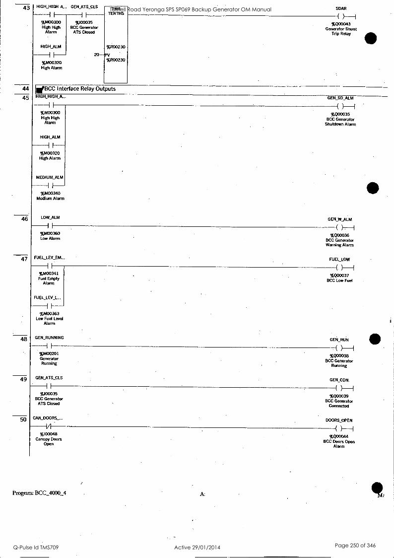
43
44
45
46
47
48
49
50
HIGH_HIGH A... GEN ATS CLS
I I
%M00300 High High
Alarm
HIGH_ALM
%M00320 High Alarm
%100035 BCC Generator
ATS Closed
TMR TENTHS
%R00230
20 -PV %R00230
SDAR
%Q00043 Generator Shunt
Trip Relay
WBCC Interface Relay Outputs
GEN_SD_ALM
( %M00300 %Q00035 High High BCC Generator
Alarm Shutdown Alarm
HIGH_ALM
%M00320 High Alarm
MEDIUM_ALM
%M00340 Medium Alarm
LOW_ALM
%M00360 Low Alarm
FUELLEV EM..
%M00341 Fuel Empty
Alarm
FUEL_LEV_L...
%M00363 Low Fuel Level
Alarm
GEN_W_ALM
%Q00036 BCC Generator Warning Alarm
FUEL_LOW
%Q00037 BCC Low Fuel
GEN_RUNNING GEN_RUN
( %M00201 %Q00038 Generator
BCC Generator Running Running
GEN_ATS_CLS
%I00035 BCC Generator
ATS Closed
CAN_DOORS_...
%100048 Canopy Doors
Open
GEN CON.
M00039 BCC Generator
Connected
Program: BCC_4000_4 A:
DOORS_OPEN
%Q00044 BCC Doors Open
Alarm
Tufnell Road Yeronga SPS SP069 Backup Generator OM Manual
Q-Pulse Id TMS709 Active 29/01/2014 Page 250 of 346

51
52
53
55
57
SEL_AUTO
I I
%I00001 Selector Switch
Auto
INILocal Control Panel Indicators
GEN_AUTO
H. %Q00045
Generator Auto Mode
SEL_AUTO
%100001 Selector Switch
Auto
LAMP_TEST_...
%100005 Lamp Test PB
SELTEST
%I00002 Selector Switch
Test
LAMP_TEST__.
I I
%100005 Lamp Test PB
SEL_MAN
I I
%100003 Selector Switch
Manual
LAMP_TEST__.
%100005 Lamp Test PB
REMOTE_STR
%M00103 Remote Start
LAMP_TEST
%100005 Lamp Test PB
AUTO_IND
%Q00001 Controls in Auto .
Indicator
TEST IND
%Q00002 Controls in Test
Indicator
MAINS_FAILED
%100033 BCC Mains
Failed
LAMP_TEST__. -I I-- w0000s
Lamp Test PB
Program: BCC_4000_4 A:
MANJ ND
%Q00003 Controls in
Manual Indicator
REM_STR_IND H %Q00004
Remote Start I ndicator
MAINS_AVAIL...
%Q00005 Mains Available
Indicator
Tufnell Road Yeronga SPS SP069 Backup Generator OM Manual
Q-Pulse Id TMS709 Active 29/01/2014 Page 251 of 346
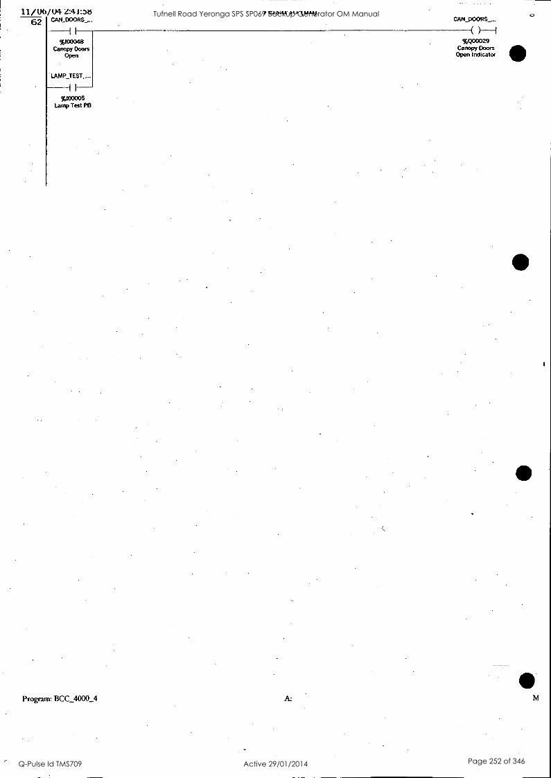
11/U6/U4 Z:41:N3 62 CAN_DOORS_...
%I00048 Canopy Doors
Open
LAMP TEST_...
%100005 Lamp Test P8
V C.LJ41: Lk) kL111)
Program: BCC_4000_4 A:
CAN_DOORS_...
%Q00029 Canopy Doors Open Indicator
Tufnell Road Yeronga SPS SP069 Backup Generator OM Manual
Q-Pulse Id TMS709 Active 29/01/2014 Page 252 of 346

1-
1
2
Er Presets Routine Move 1 to the Sequence Counter ALW ON
I I
%S00007 Always ON
410-ograrn: BCC_4000_4
MOVE INT
1
IN Q -SEQ CNT
%R00001 Sequence Counter
A:
Tufnell Road Yeronga SPS SP069 Backup Generator OM Manual
Q-Pulse Id TMS709 Active 29/01/2014 Page 253 of 346

1
2
3
4
5
WGenerator Modbus RTU Slave Interface 40001 - Generator Sequence Number ALW ON
I I
%S00007 Always ON
SEL AUTO-
%100001 Selector Switch
Auto
ALW ON
%S00007 Always ON
MOVE BOOL
48
IN
AUTO_IND-
%Q00001 Controls in Auto
Indicator
ALW ON
%S00007 Always ON
MOVE BOOL
48
IN
GEN_OFF-
%M00101 Generator OFF
ALW_ON
I
%S00007 Always ON
MOVE BOOL
16
IN
-MODBUS_INP...
%R00002 Modbus Digital
Inputs
-MODBUS_OUT...
%R00005 Modbus Digital
Outputs
-MODBUS STA...
%R00008 Modbus Status 1
GEN_RUNNING-
%M00201 Generator Running
MOVE BOOL
16
IN - MODBUS STA...
%R00009 Modbus Status .2
Program: BCC_4000_4 A: MOD]
Tufnell Road Yeronga SPS SP069 Backup Generator OM Manual
Q-Pulse Id TMS709 Active 29/01/2014 Page 254 of 346

6 ALW ON
II
%S00007 Always ON
HIGH_HIGH ALM - %M00300
High High Alarm
*gram BCC 4000_4
MOVE BOOL
100
IN -MODBUS ALA...
%R00010 Modbus Alarms
A: MOD]
Tufnell Road Yeronga SPS SP069 Backup Generator OM Manual
Q-Pulse Id TMS709 Active 29/01/2014 Page 255 of 346

Imp Generator OFF State SEL_AUTO SEL_TEST SEL_MAN
VI VI VI
V00001 %100002 %100003 Selector Switch Selector Switch Selector Switch
Auto Test Manual
GEN_OFF
1 ff---- %M00101
Generator OFF
1-
MOVE INT
IN -SEQ_CNT
%R00001 SeqUence Counter
TMR TENTHS
%R00100
25-pv cfc,R00100
GEN_OFF
%mom. Generator OFF
IWGenerator Automatic Start and Stop Logic MAINS_FAIL_S... MAINS_FAIL_S...
II V %M00117
Mains Fail Start
REMOTE_STR
%M00103 Remote Start
%M00104 Mains Failed
Stop
REMOTE_STR REMOTE STP
TEST STR
1.1
%M00106 Test Start
AUTO TEST
%M00102 Auto & Test Start / Stop
MAI NS_FAILED
1 1
%100033 BCC Mains
Failed
%M00103 %M00105 Remote Start . Remote Stop
TEST_STP
v1
%M00107 Test Stop
GEN_OFF HIGH_HIGH_A... HIGH ALM MEDIUM_ALM
V V V V %M00101 %M00300 %M00320 %M00340
Generator OFF High High Alarm High Alarm Medium Alarm
TMR TENTHS
%R00139
300- PV %R00139
TMR TENTHS
%R00103
5 - PV %R00103
AUTO_TEST S...
%M00102 Auto & Test Start / Stop
MA1NS_FAILS...
%M00117 Mains Fail Start
Tufnell Road Yeronga SPS SP069 Backup Generator OM Manual
Q-Pulse Id TMS709 Active 29/01/2014 Page 256 of 346

10
v1 %100033
BCC Mains Failed
SFJ_AUTO
I I
%00001 Selector Switch
Auto
SELAUTO
TMR TENTHS
%R00106
1200 -PV %R00106
96100036 %M00105 BCC Remote Remote Stop
Start
MARIS_ATS C... GEN_RUNNING
%M00382 %M00201 Mains ATS Generator
Failed to Close Running
REMOTE_STR
%100001 Selector Switch
Auto
SELJEST
%100002 Selector Switch
Test
%M00103 Remote Start
REM STP
%100037 BCC Remote
Stop
HIGH_HIGH_...
1 1- 96M00300 High High
Alarm
HIGH_ALM
I I
%M00320 High Alarm
MEDIUM_ALM
%M00340 Medium Alarm
TMR TENTHS
%R00112
5 -PV %R00112
MAINS_FAIL_S...
%M00104 Mains Failed
Stop
REMOTE_STR
%M00103 Remote Start
Program: BCC_4000_4
TMR TENTHS
%R00115
10 -PV %R00115
REMOTEE_
_S-STPJJ
%M00105 Remote Stop
TEST_STR
%M00106 Test Start
Tufnell Road Yeronga SPS SP069 Backup Generator OM Manual
Q-Pulse Id TMS709 Active 29/01/2014 Page 257 of 346

2-
11
12
13
14
15
16
17
SEL TEST
14
%100002 Selector Switch
Test
10 -
TMR TENTHS
%R00118
PV %R00118
TEST STP
%M00107 Test Stop
eGenerator Sequence 1 -- 2 Starting the Generator
GEN_RUN_OFF HIGH_H1GH_A... HIGH_ALM MEDIUM_ALM
VI 14 I/I %M00108 %M00300 %M00320 %M00340
Generator Run High High Alarm High Alarm Medium Alarm Off
SPD STP CRK
I
%100017 Crank Cutout
Relay
STEP_1
OFDT TENTHS
%R00121
150 -PV %R00121
SEL AUTO AUTO TESTS... STEP I
I I II II
%100001 %M00102 %M00001 Selector Switch Auto & Test Step Sequence
Auto Start / Stop No.1
SEL_TEST AUTO TEST ...
I I I.
%100002 %M00102 Selector Switch Auto & Test
Test Start / Stop
SEL MAN MAN STR_PB
I I II
%100003 %100008 Selector Switch Manaul Start PB
Manual
MOVE INT
IN - SEQCNT
%R00001 Sequence Counter
GEN_RUN_OFF
%M00108 Generator Run
Off
ENABLE_OFFL..
%M00001 %M00109 Step Sequence
Enable No.1 Generator to go
Oft ine
oGenerator. Sequence 2 -- 3 Generator Running at Rated Speed Generator Warmup Time
SEJ_AUTO GEN_RUNNING STEP 2 E
I
%100001 Selector Switch
Auto
SEL_TEST
II
%100002 Selector Switch
Test
I I II
%M00201 %M00002 Generator Step Sequence Running No.2
50
TMR TENTHS
%R00124
-PV %R00124
3-
MOVE INT
1
IN
Program: BCC...4000_4 A:
-SEQ_CNT
%R00001 Sequence Counter
Tufnell Road Yeronga SPS SP069 Backup Generator OM Manual
Q-Pulse Id TMS709 Active 29/01/2014 Page 258 of 346

LI / MI/ %PI 4::.71.1:JI
18 SELMAN GEN_RUNNING STEP 2_E
I I I I-- w00003 Tem00201 %M00002
Selector Switch Generator Step Sequence Manual Running No.2
19
20
21
22
23
50-
TMR TENTHS
%R00127
PV %R00127
V...1.041.1. av k L./.111
SELAUTO SPD_STP_CRK AUTO TEST S... STEP 2_E
I I Vl VI H-- 10100001
Selector Switch Auto
SELTEST
II
%100002 Selector Switch
Test
%100017 %M00102 %M00002 Crank Cutout Auto & Test Step Sequence
Relay Start / Stop No.2
1-_I
SELAUTO SPD_STP_CRK AUTO TEST S... STEP 2_E
I
%100001 Selector Switch
Auto
SELTEST
%100002 Selector Switch
Test
I I
%100017 %M00102 %M00002 - Crank Cutout Auto & Test Step Sequence
Relay Start / Stop No.2
SELMAN SPD_STP CRK MAN_STP_PB STEP_2_E
MOVE INT
1
N Q
9-
%100003 %l00017 %100009 %M00002 Selector Switch Crank Cutout Manual Stop PB Step Sequence
Manual Relay No.2
SELMAN SPD STP CRK MAN_STP_PB STEP_2_E
I I V1-
MOVE INT
1
IN
1-
%100003 %100017 %100009 %M00002 Selector Switch Crank Cutout Manual Stop PB Step Sequence
Manual Relay No.2
MOVE INT
1
IN
9-1
mfGenerator Sequence 3 -- 4 Generator Running at. Rated Speed Transfer to Generator ATS
Program: BCC_4000_4
MOVE INT
1
N Q
3-
MOVE INT
1
IN -SEQCNT
%R00001 Sequence Counter
- SEQ_CNT
'00001 Sequence Counter
-SEQ_CNT
%R00001 Sequence Counter
-SEQ_CNT
%R00001 Sequence Counter
-SEQ_CNT.
%R00001 Sequence Counter
A:
Tufnell Road Yeronga SPS SP069 Backup Generator OM Manual
Q-Pulse Id TMS709 Active 29/01/2014 Page 259 of 346

II 1/1 II. I 1- 1,M00201 %100034 %100035 %M00004 Generator BCC Mains ATE BCC Generator Step Sequence Running Closed ATS Closed No.4
5-
24
25
26
27
28
29
SEL_AUTO
-H %100001
Selector Switch Auto
SELTEST
GEN_RUNNING STEP 3
9000002 Selector Switch
Test
%M00201 %M00003 Generator Step Sequence Running No.3
4-
SELMAN GEN RUNNING MAN TRF_GE...
I II 96100003 %M00201 %100011 %M00003
Selector Switch Generator Manual Transfer Step Sequence Manual Running to Generator PB No.3
MOVE INT
1
IN Q
STEP_3
SEL_AUTO AUTO TEST_S... STEP 3
%100001 Selector Switch
Auto
SELTEST
it
1.100002 Selector Switch
Test
%M00102 %M00003 Auto & Test Step Sequence Start / Stop No.3
SELMAN MAN STP PB STEP 3
. II
9--
%100003 %100009 %M00003 Selector Switch Manual Stop PB Step Sequence
Manual No.3
MOVE INT
1
IN
9-
WGenerator Sequence 4 -- 5 Generator Running Online
MOVE INT
1
IN
-SEQ_CNT
96800001 Sequence Counter
MOVE INT
1.
4-SIN Q -5EQ_CNT
%R00001 Sequence Counter
-SEQ_CNT
%R00001 Sequence Counter
- SEQ_CNT
%R00001 Sequence Counter
SEL_AUTO GEN_RUNNING MAINS_ATS C._ GEN_TS CLS STEP _4
I I
%100001 Selector Switch
Auto
SELTEST
I I
%100002 Selector Switch
Test
Program: BCC_4000_4
MOVE INT
1
IN
A:
-SEQ_CNT
%R00001 Sequence Counter
Tufnell Road Yeronga SPS SP069 Backup Generator OM Manual
Q-Pulse Id TMS709 Active 29/01/2014 Page 260 of 346
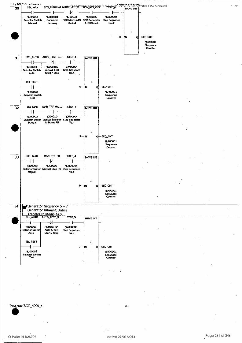
11 / UV/ (Pt I.,:..n/3-01
30 SELMAN GEN_RUNNING MAINS ATS_C... GEN ATS CLS
I IA i I 1I ---- '000003 %M00201 %100034 000035 %M00004
Selector Switch Generator BCC Mains ATS BCC Generator Step Sequence Manual Running Closed ATS Closed No.4'
31
32
33
34
t.lO4a 19.."
STEP 4
SELAUTO
I I
000001 Selector Switch
Auto
SEL TEST
II
%100002 Selector Switch
Test
AUTO TEST S... STEP_4
I I
0400102 %M00004 Auto & Test Step Sequence Start / Stop No.4
SEL MAN MAN TRF MAI... STEP 4
II II II
9
%100003 %100010 %M00004 Selector Switch Manual Transfer Step Sequence
Manual to Mains PB No.4
SELMAN MAN_STP_PB STEP 4
II 1/1 II
MOVE INT
1
IN
3-
%100003 %100009 %M00004 Selector Switch Manual Stop PB Step Sequence
Manual No.4
9
ofGenerator Sequence 5 -- 7 Generator Running Online Transfer to Mains ATS
SELAUTO AUTO TEST S... STEP_5
I I
%100001 Selector Switch
Auto
SEL TEST
II
%l00002 Selector Switch
Test
Program: BCC_4000_4
V II
%M00102 %M00005 Auto & Test Step Sequence Start / Stop No.5
MOVE INT
1
IN
MOVE INT
1
IN
MOVE INT
1
7-IN Q - SEQ_CNT
5
-SEQ_CNT
%R00001 Sequence Counter
-SEQ_CNT
%R00001 Sequence Counter
-SEQ_CNT
%R00001 Sequence Counter
MOVE INT
1
'IN -SEQ_CNT
%R00001 Sequence Counter
%R00001 Sequence Counter
A:
Tufnell Road Yeronga SPS SP069 Backup Generator OM Manual
Q-Pulse Id TMS709 Active 29/01/2014 Page 261 of 346

36
37
38
39
40
41
42
43
SEL_MAN MAN TRF_MAI... STEP_5
I I
%100003 %100010 %M00005 Selector Switch Manual Transfer Step Sequence
Manual to Mains PB No.5
SEL MAN MAN_STP PB STEP 5
MOVE INT
1
7 -IN Q-SEQ_CNT
%R00001 Sequence Counter
%100003 %100009 %M00005 Selector Switch Manual Stop PB Step Sequence
Manual No.5
7
MOVE INT
SEQ_CNT
%R00001 Sequence Counter
ENABLE_OFFL...
(0-1 %M00109
Enable Generator to go
Offline
WGenerator Sequence 7 -- 9 Generator Running Mains ATS Closed
MA1NS_ATS C... GEN_ATS CLS ENABLE_OFFL.. STEP 7
II Vl VI II- %,100034 %100035 %M00109 %M00007
BCC Mains ATS BCC Generator Enable Step Sequence Closed ATS Closed Generator to go No.7
Offline
9-
"'Generator Sequence 7 -- 3 Generator Running Mains ATS Closed Return to Step 3
MAINS ATS_C... GEN_ATS CLS ENABLE_OFFL...
MOVE INT
1
IN SEQ_CNT
%R00001 Sequence
. Counter
STEP_?
I I VI l I I I-- %100034 %100035 %M00109 %M00007
BCC Mains ATS BCC Generator Enable Step Sequence Closed ATS Closed Generator to go No.7
Offline
MOVE INT
1
3-1N Q- SEQ_CNT
%R00001 Sequence Counter
ENABLE OFFL..
(2)-1 %M00109
Enable Generator to go
Offline
Generator Sequence 9 -- 1
Generator Cool Down SELAUTO STEP 9
I I
%100001 Selector Switch
Auto
SELTEST
I I
%100002 Selector Switch
Test
%M00009 Step Sequence
No.9
TMR TENTHS
%R00130
3000 -PV %R00130
MOVE INT
1
1 -IN -SEQ_CNT
%R00001 Sequence Counter
Program: BCC_4000_4 A:
Tufnell Road Yeronga SPS SP069 Backup Generator OM Manual
Q-Pulse Id TMS709 Active 29/01/2014 Page 262 of 346

44
45
46
47
48
49
50
51
52
53
SEL_MAN I LI' 9 TMR TENTHS
.
%R00133
%R00133
MOVE INT
1
Q-SEQ_CNT
-
%/200031 Sequence Counter
I I I
%100003 %M00009 Selector Switch Step Sequence
Manua! No.9
10 -PV 1 -IN
WGenerator Sequence 9 - 2 Generator Restart
SEL AUTO AUTO TEST S... STEP 9
I -I I i
TMR TENTHS
%R00136
%R00136
MOVE INT
1
IN Q-SEQ_CNT
-
. %R00001 Sequence Counter
I
96100001 Selector Switch
Auto
SEL_TEST
I I
%M00102 %M00009 Auto & Test Step Sequence Start / Stop No.9
10 2 -,PV %100002
Selector Switch Test
iiGenerator High High Alarm Generator Shut Down
HIGH_HIGH_A... HH_ALM_OS1
t)----1 %M00300 %M00110
High High Alarm High High Alarm One Shot
HH ALM_OS1
I
MOVE INT
%R00001 Sequence Counter
I
%M00110 High High Alarm
One Shot
1-IN 1
Q-SEQ_CNT
Generator High Alarm Generator Not Running Move to Stop Mode, Step 1
HIGH_ALM SPO_STP_CRK ' H_ALM_OS1
I VI (1)--1 %M00320 %100017
%M00111 High Alarm Crank Cutout High Alarm One Relay Shot
HALM 0S1
II
MOVE INT
Q
-
-SEQ_CNT
%R00001 Sequence Counter
%M00111 High Alarm One
Shot
1 -IN
WGenerator High Alarm .
Generator Running, Move to Cool Down Mode, Step 9
Program: BCC_4000_4 A:
Tufnell Road Yeronga SPS SP069 Backup Generator OM Manual
Q-Pulse Id TMS709 Active 29/01/2014 Page 263 of 346

55
56
57
58
59
60
61
62
63
HIGH_ALM SPD STP CRK
%M00320 96100017 High Alarm Crank Cutout
Relay
H_ALM_OS2
%M00112 High Alarm One
Shot
MOVE INT
1
N Q
H__ALM_OS2
%M00112 High Alarm One
Shot
-SEQ_CNT
%R00001 Sequence Counter
ilenerator Medium Alarm le&nerator Not Running. Move to Stop Mode. Step 1
MEDIUM_ALM SPD STP_CRK
II V1
%M00340 %100017 Medium Alarm Crank Cutout
Relay
M AUYI OS1
iI
%M00113 Medium Alarm
One Shot
1-
MOVE INT
IN Q -SEQ_CNT
%R00001 Sequence Counter
M_ALILOS1
%M00113 Medium Alarm
One Shot
EpGenerator Medium Alarm Generator Running. Move to Transfer to Mains ATS. Step 7
MEDIUM ALM SPD_STP CRK
I I
%M00340 %100017 Medium Alarm Crank Cutout
Relay
M_ALM 0S2
II
%M00114 Medium Alarm
One Shot
7-
MOVE INT
1
IN -SEQ_CNT
%R00001 Sequence Counter
M_ALM_OS2
%M00114 Medium Alarm
One Shot
WMains ATS Fail To Close Alarm Generator Not Running. Move to Generator Stopped. Step 1
GEN_RUNNING MAINSATS_C... M ATS_ALM_..
11-1 %M00201 96M00382 %M00115 Generator Mains ATS Mains ATS Running Failed to Close Alarm One Shot
Alarm
Program: BCC_4000_4 A:
Tufnell Road Yeronga SPS SP069 Backup Generator OM Manual
Q-Pulse Id TMS709 Active 29/01/2014 Page 264 of 346

MATS ALM_...
%M00115 Mains ATS
Alarm One Shot
1-1
64
65
66
67
68
69
MOVE INT
1
N Q -SEQ_CNT
%R00001 Sequence Counter
'Mains ATS Fail To Close Alarm Generator Running. Move to Transfer to Generator ATS. Step 4
GEN_RUNN1NG MAINS ATS C... AUTO TEST S... M_ATS_ALM_...
%M00201 %M00382 %M00102 96M00116 Generator Mains ATS Auto & Test Mains ATS Running Failed to Close Start / Stop
Alarm One Shot Alarm
M_ATS_ALM_...
1---- 96M00116 Mains ATS
Alarm One Shot
4--
MOVE INT
1
IN -SEQCNT
%R00001 Sequence Counter
EIGenerator Sequence Counter is Out of Range. Reset to Step 1
ALW_ON LT INT
I I
%S00007 Always ON
sEpstrr -IN' %R00001 Sequence Counter
ALW ON
II
%S00007 Always ON
1 -1N2
EQ INT
SEQ_CNT-IN1
%R00001 Sequence Counter
6 - I N2
MOVE INT
1
1 - IN
MOVE INT
1
1 - IN
- SEQCNT
%R00001 Sequence Counter
-SEQ_CNT
%R00001 Sequence Counter
Program: BCC_4000_4 A: Sl
Tufnell Road Yeronga SPS SP069 Backup Generator OM Manual
Q-Pulse Id TMS709 Active 29/01/2014 Page 265 of 346

71
72
ALW ON
I I
%S00007 Always ON
EQ INT
SEQ_CNT-IN1
I.1200001 Sequence Counter
ALW ON
I I
%S00007 Always ON
8 -1N2
GT INT
SEQ_CNT-IN1
%R00001 Sequence Counter
8-1142
Program: BCC_4000_4
MOVE INT
1
1-IN
MOVE INT
1
1 -IN
SEQ_CNT
%R00001 Sequence .
Counter
- SEQ_CNT
%R00001 Sequence Counter
A:
Tufnell Road Yeronga SPS SP069 Backup Generator OM Manual
Q-Pulse Id TMS709 Active 29/01/2014 Page 266 of 346

1 I Generator High High Alarms
2
3
EM STP ALM
%M00301 Emergency Stop Alarm
MEN _ALM
%M00302 MEN Alarm
OIL P SD ALM
%M00303 Low Oil
Pressure -
Shutdown Alarm
ENG T SD_A...
%M00304 High Engine
Temperature Shutdown
Alarm RAD_WATER__
%M00305 Low Radiator Water Level
Alarm
SPD OVER_A...
%M00306 Over Speed
Alarm
HIGH HIGH A...
%M00300 High High Alarm
WGenerator High Alarms
4 I SPD_UNDER_...
%M00321 Under Speed
Alarm
VOLTS_UNDE...
%M00322 Alternator
Voltage Under Alarm
VOLTS_OVER...
%M00323 Alternator
Voltage Over Alarm
GEN_CB_TRI...
%M00324 Generator CB
Tripped Alarm
ALT_TEMP A...
5
%M00325 Alternator High
Temperature Alarm
HIGH_ALM
%M00320 High Alarm
Generator Medium Alarms
Program: BCC_4000_4 A: ALA
Tufnell Road Yeronga SPS SP069 Backup Generator OM Manual
Q-Pulse Id TMS709 Active 29/01/2014 Page 267 of 346

IL / %/V/ kr+ L.:J4-tOLAJ
6
7
FUELJ.EV_EM... V CLJ41.
%M00341 Fuel Empty
Alarm
FAIL_TO STR..
%M00342 Fail to Start
Alarm
MAINS_ATS_...
II
%M00381 Mains ATS
Failed to Open Alarm
GEN_ATS_CL..
II
%M00384 Generator ATS Failed to Close
Alarm
MEDIUM_ALM
%M00340 Medium Alarm
"6'
Generator Low Alarms
Program: BCC_4000_4 A:
Tufnell Road Yeronga SPS SP069 Backup Generator OM Manual
Q-Pulse Id TMS709 Active 29/01/2014 Page 268 of 346

9
10
O1L_P W ALM LOW_ALM
%M00360 Low Alarm
%M00361 Low Oil
Pressure Warning Alarm
ENG T WALM
%M00362 High Engine Temperature
Warning Alarm
FUELLEV L..
%M00363 Low Fuel Level
Alarm
BAT CHG AC...
%M00364 Battery Charg
AC Alarm
BAT CONT L..
%M00365_ Control Battery
Charger Low Voltage Alarm
BAT STR_LO...
%M00366 Start Battery Charger Low
Voltage Alarm
MA1NS_ATS_....
%M00382 Mains ATS
Failed to Close Alarm
GEN ATS_OP...
%M00383 Generator ATS Failed to Open
Alarm
Generator Emergency Stop Alarm EM_STOP_PB
%100004 Emergency Stop
PB
EM_STP_ALM ALM_RESET_...
%M00301 %100006 Emergency Stop Alarm Reset PB
Alarm
Program: BCC_4000_4 A:
EM_STP_ALM
%M00301 Emergency Stop
Alarm
Tufnell Road Yeronga SPS SP069 Backup Generator OM Manual
Q-Pulse Id TMS709 Active 29/01/2014 Page 269 of 346

11 EM_STP_ALM
12
13
14
15
16
17
18
So-% EM_STOP_IND
I I
%M00301 Emergency Stop Alarm
LAMP_TEST_-.
I
)---1 '
%Q00010 Emergency Stop
Indicator
411 F
%100005 Lamp Test PB
EfGenerator MEN Alarm MEN_FLT
MEN_ALM
%100024 MEN Fault Relay
MEN_ALM ALM_RESET__.
( )----1 %M00302 MEN Alarm
I V %M00302 %100006
MEN Alarm Alarm Reset PB
MEN_ALM MEN_FLT IND
I
%M00302 MEN Alarm
LAMP TEST__
( )----I %Q00011 MEN Fault Indicator
II
%100005 Lamp Test PB
spenerator Low Oil Pressure Shut Down Alarm OIL_P LOW SO OIL_P_DLY
OIL P_SO_ALM
I I I I
%l00041 %M00207 tow Oil Pressure Oil Pressure
Shutdown Alarm Delay
OIL_P_SD_ALM ALM_RESET ...
( )----1 %M00303
Low Oil Pressure Shutdown Alarm
I VI %M00303 %100006
Low Oil Pressure Alarm Reset P8 Shutdown Alarm
OIL_P_SD ALM OIL_P_LOW_S...
I I
%M00303 Low Oil
Pressure Shutdown
Alarm LAMP_TEST__.
I I
( )----I %Q00012
Low Oil Pressure Shutdown Indicator
%100005 Lamp Test PB
*Generator High Engine Temperature Shut Down Alarm
Program: BCC_4000_4
Tufnell Road Yeronga SPS SP069 Backup Generator OM Manual
Q-Pulse Id TMS709 Active 29/01/2014 Page 270 of 346

19
20
21
22
23
24
25
ENG T_HI_SD STR_UP_DLY
II II
%100043 %M00208 High Engine Startup Alarm Temperature Delay
Shutdown
ENG T_SO_ALM ALM_RESET_...
Tem00304 %100006 High Engine Alarm Reset PB Temperature
Shutdown Alarm
ENG_T_SD ALM
ENG_T SD_ALM
%M00304 High Engine Temperature
Shutdown Alarm
ENG_T_HI_SD...
%M00304 %Q00014 High Engine High Engine
Temperature Temperature Shutdown Shutdown
Alarm Indicator LAMP TEST
%100005 Lamp Test PB
ufGenerator Low Radiator Water Level Alarm RAD WATER__
%100045 Low Radiator Water Level
TMR TENTHS
%R00300
50 -,PV %R00300
RAD WATER__
%M00315 Radiator Water Level Low Delay
RAD_WATER_... RAD_WATER_...
%M00315 Radiator Water Level Low Delay
RAD WATER_... ALM_RESET_...
IA ol00305 %100006
Low Radiator Alarm Reset PB Water Level
Alarm
RAD_WATER_...
II
%M00305 Low Radiator Water Level
Alarm
LAMP TEST__
II
%I00005 Lamp Test PB
%M00305 Low Radiator Water Level
Alarm
RAD WATER__
() %Q00016
Low Radiator Water Level
Indicator
WGenerator Over Speed Alarm
Program: BCC_4000_4 A:
Tufnell Road Yeronga SPS SP069 Backup Generator OM Manual
Q-Pulse Id TMS709 Active 29/01/2014 Page 271 of 346
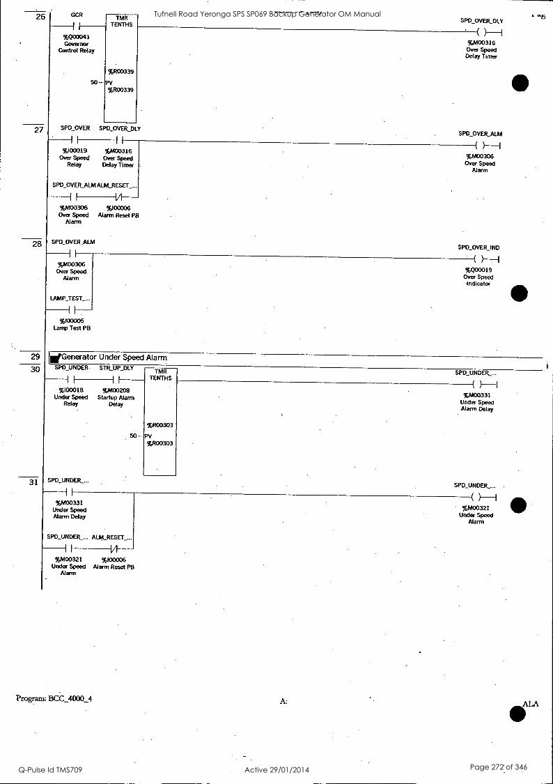
26
27
28
29
30
31
GCR
%Q00041 Governor
Control Relay
TMR TENTHS
%R00339
50 --'PV %R00339
SPD OVER SPD OVER_DLY
11 iF
%l00019 %M00316 Over Speed Over Speed
Relay Delay Timer
SPO OVER ALM ALM_RESET_...
V %M00306 %100006
Over Speed Alarm Reset PB Alarm
SPD OVER_ALM
%M00306 Over Speed.
Alarm
LAMP TEST__
iJ
%100005 Lamp Test PB
SPD OVER_DLY
%M00316 Over Speed Delay Timer
SPD_OVER_ALM
%M00306 Over Speed
Alarm
SPD OVER_IND
%Q00019 Over Speed
Indicator
dGenerator Under Speed Alarm SPO UNDER. STR_UP DLY
%100018 %M00208 Under Speed Startup Alarm
Relay Delay
SPD_UNDER__.
TMR TENTHS
%R00303
50 - PV %R00303
SPD_UNDER_...
(
%M00331 Under Speed Alarm Delay
SPD_UNDER_...
%M00331 Under Speed Alarm Delay
SPD_UNOER_... ALM_RESET__.
V %M00321 %I00006
Under Speed Alarm Reset PB Alarm
Program: BCC_4000_4 A:
%M00321 Under Speed
Alarm
Tufnell Road Yeronga SPS SP069 Backup Generator OM Manual
Q-Pulse Id TMS709 Active 29/01/2014 Page 272 of 346

32
33
34
35
36
37
SPO UNDER__
II
%N100321 Under Speed
Alarm
LAMP TEST__
%100005 Lamp Test PB
--0 SPD_UNDER_I...
( -H %Q00020
Under Speed Indicator
*Generator Under Voltage Alarm VOLTS UNDER STR UP_OLY
%100020 %M00208 Under Voltage Startup Alarm
Relay Delay
VOLTS_UNDE..
F
%M00332 Under Voltage Alarm Delay
TMR TENTHS
%R00306
5O -PV %R00306
VOLTS_UNDE...
( %M00332
Under Voltage Alarm Delay
VOLTS_UNDE.. ALM_RESET_...
1 IA %M00322 %100006 Alternator Alarm Reset PB
Voltage Under Alarm
VOLTS_UNDE...
%M00322 Alternator
Voltage Under Alarm
VOLTS_UNDE... VOLTS_UNDE...
%M00322 Alternator
Voltage Under Alarm
LAMP_TEST
if
%100005 Lamp Test PB
%Q00022 Alternator
Voltage Under Indicator
iiGenerator Over Voltage Alarm VOLTS OVER STR_UP_DLY
II II
%100021 %M00208 Over Voltage Startup Alarm
Relay Delay
TMR TENTHS
%R00309
50 -PV 9GRO0309
VOLTS OVER__
(
%M00333 Over Voltage Alarm Delay
Tufnell Road Yeronga SPS SP069 Backup Generator OM Manual
Q-Pulse Id TMS709 Active 29/01/2014 Page 273 of 346

39
40
41
42
43
44
45
VOLTS_OVER_...
II
%M00333 Over Voltage Alarm Delay
VOLTS OVER ... ALM_RESET_...
H V %M00323 %100006 Alternator Alarm Reset PB
Voltage Over Alarm
VOLTS_OVER.....
II
%M00323 Alternator
Voltage Over Alarm
LAMP TEST__
%100005 Lamp Test PB
VOLTS OVER--.
%M00323 Alternator
Voltage Over Alarm
VOLTS_OVER_...
%Q00023 Alternator
Voltage Over Indicator
WGenerator CB Tripped Alarm GEN_CB TRIP GEN_CB_TRIP...
%100023 Generator CB
Tripped
GEN CB_TRIP... ALM_RESET_...
II
%M00324 %100006 Generator CB Alarm Reset PB Tripped Alarm
GEN_CB TRIP..
II
%M00324 Generator CB Tripped Alarm
LAMP TEST__
If
%l00005 Lamp Test PB
%M00324 Generator CB
Tripped Alarm
GEN_CB_TRIP...
%Q00025 Generator CB
Tripped Indicator
WGenerator High Alternator Temperature Alarm ALT TEMP STR_UP_DLY ALT_TEMP_ALM
%100022 %M00208 Alternator High Startup Alarm
Temperature Delay Relay
ALT TEMP_ALM ALM_RESET_...
I
%M00325 %100006 Alternator High Alarm Reset PB
Temperature Alarm
Program: BCC_4000_4 A:
%M00325 Alternator High
Temperature Alarm
Tufnell Road Yeronga SPS SP069 Backup Generator OM Manual
Q-Pulse Id TMS709 Active 29/01/2014 Page 274 of 346

46
47
48
49
50
51
S
ALT TEMP_ALM ALT TEMP_IND
%M00325 Alternator High Temperature
Alarm
LAMP_TEST_...
I I
%100005 Lamp Test PB
%Q00024 Alternator. High Temperature
Indicator
IWGenerator Fuel Level Empty Alarm FUEL_LEV EM...
II
%,100047 Fuel Empty
FUEL_LEV EM...
I I
TMR TENTHS
%1200312
50 -PV %R00312
%M00351 Fuel Level Empty
Alarm Delay
FUEL_LEV EM... ALM_RESET_...
II
%M00341 %100006 Fuel Empty Alarm Reset PB
Alarm
FUEL_LEV_EM...
%M00351 Fuel Level'Empty
Alarm Delay
FUELLEV EM...
%M00341 Fuel Empty
Alarm
FUEL_LEV EM... FUEL_LEV EM...
%M00341 Fuel Empty
Alarm
LAMP TEST
If
%100005 Lamp Test PB
%Q00017 Fuel Empty Indicator
WGenerator Fail To Start Alarm FA1L_STR_CNT
II
%M00204 Failed to Start
Counter
FAIL_TO_STR... ALM_RESET_...
%M00342 %100006 Fail to Start Alarm Reset PB
Alarm
FAIL_TO_STR_...
%M00342 Fail to Start
Alarm
Tufnell Road Yeronga SPS SP069 Backup Generator OM Manual
Q-Pulse Id TMS709 Active 29/01/2014 Page 275 of 346

53
54
55
56
57
58
59
60
FAIL_TO_STR_... FAIL_TO_STR__.
I I
%M00342 Fail to Start
Alarm
LAMP TEST ...
1 /-1 %Q00021
Fail to Start Indicator
1 1
%100005 Lamp Test PB
WGenerator Low Oil Pressure Warning Alarm OIL_P_LOW W . OIL_P_DLY OIL_P_W_ALM
0
I 1 1
%100042 %M00207 Low Oil Pressure Oil Pressure
Warning Alarm Delay
OIL_P W ALM ALM_RESET_...
)--1 %M00361
Low Oil Pressure Warning Alarm
OIL_P_LOW W...
)---1
I 14
%M00361 %100006 Low Oil Pressure Alarm Reset PS Warning Alarm
OIL_P_W_ALM
%M00361 Low Oil
Pressure Warning Alarm
LAMP_TEST_...
%Q00013 Low Oil Pressure
Warning Indicator
I I
%I00005 Lamp Test PB
ErGenerator High Engine Temperature Warning Alarm ENG T HI _W STR_UP_DLY ENG_T_W_ALM
, %100044 vioozoa High Engine Startup Alarm
Temperature Delay Warning
ENG_T W_ALM ALM_RESET ...
' '
)---I 9w00362
High Engine Temperature
Warning Alarm
ENG T_HI W I...
I VI %M00362. %100006
High Engine Alarm Reset PB Temperature
Warning Alarm
ENG T_W_ALM
I I
%M00362 High Engine
Temperature Warning Alarm
LAMP TESL...
)---1 %Q00015
High Engine Temperature
Warning Indicator
I
%100005 Lamp Test PB
WGenerator Fuel Level Low Alarm
Program: BCC_4000_4 A:
Tufnell Road Yeronga SPS SP069 Backup Generator OM Manual
Q-Pulse Id TMS709 Active 29/01/2014 Page 276 of 346

61
62
63
64
65
66
FUELLEV LOW
9000046 Low Fuel Level
FlJEL_LEV LO...
TMR TENTHS
%1200315
50 -PV %R00315
FUEL_LEV_LO...
%M00373 Fuel Level Low Alarm Delay
%M00373 Fuel Level Low Alarm Delay
FUEL_LEV_LO... ALM_RESET_...
%M00363 96100006 Low Fuel Level Alarm Reset PB
Alarm
FUEL_LEV_LO...
II
%M00363 Low Fuel Level
Alarm
LAMP TEST ...
II
%l00005 Lamp Test PB
FUEL_LEV_LO...
%M00363 Low Fuel Level
Alarm
FUEL_LEV LO...
%Q00018 Low Fuel Level
Indicator
EGenerator Battery Charger AC Fail Alarm BAT CHG_AC
I I
%l00025 Battery Charger
AC Relay
BAT CHG_AC__.
I I
TMR TENTHS
%R00318
1200 - pv %R00318
BAT_CHG_AC_...
(
%M00374 Battery Charger AC Failure Delay
BAT CHG_AC_...
%M00374 Battery Charger AC Failure Delay
BAT_CHG_AC_... ALM_RESET_...
H V1
%M00364 %100006 Battery Charger Alarm Reset PB
AC Alarm
BCC 4000_4
(
%M00364 Battery Charger
AC Alarm
A: ALP
Tufnell Road Yeronga SPS SP069 Backup Generator OM Manual
Q-Pulse Id TMS709 Active 29/01/2014 Page 277 of 346

67
68
69
70
71
72
73
BAT_CHG_AC BAT_CHG_AC_...
%M00364 %Q00026 Battery Charger Battery Charger
AC Alarm AC Indicator
LAMP TEST_...
%l00005 Lamp Test PB
*Generator Control Battery Low Voltage Alarm BAT CONT LO...
%l00026 Control Battery
Charger Low Voltage
TMR TENTHS
%R00321
300- PV %R00321
BAT CONT_LO...
(
%M00375 Control Battery
Low Voltage Delay
BAT CONT LO... BAT_CONT_LO...
%M00375 Control Battery
Low Voltage Delay
BAT_CONT 10...ALM_RESET_...
%M00365 %100006 Control Battery Alarm Reset PB
Charger Low Voltage Alarm
BAT CONT LO...
%M00365 Control Battery
Charger Low Voltage Alarm
LAMP TEST ...
%100005 Lamp Test PB
( ) I
%M00365 Control Battery
Charger Low Voltage Alarm
BAT_CONT LO...
*Generator Start Battery Low Voltage Alarm
%Q00027 Control Battery
Charger Low Voltage
Indicator
BAT STR_LO...
I .
%100027 Start Battery Charger Low
Voltage
TMR TENTHS
%R00324
600 -PV %R00324
BAT_STR_LO...
( ) I
%M00376 Start Battery Low Voltage
Delay
Tufnell Road Yeronga SPS SP069 Backup Generator OM Manual
Q-Pulse Id TMS709 Active 29/01/2014 Page 278 of 346

75
76
77
78
79
82
BAT_STR_LO... BAT_STR_LO...
I I
%M00376 Start Battery Low Voltage
Delay
BAT_STR_LO... ALM_RESET_...
Vi
\ 1-1 9;M00366
Start Battery Charger Low
Voltage Alarm
BAT_STR_LO...
H--I
H %M00366 %100006
Start Battery Alarm Reset PB
Charger Low Voltage Alarm
BAT STR_LO...
* I
%M00366 Start Battery
. Charger Low Voltage Alarm
LAMP TEST_...
%Q00028 Start Battery Charger Low
Voltage .
Indicator
II
%100005 Lamp Test PB
(Mains ATS Fail to Open Alarm MA1NS_ATS 0...GEN_ATS CIS... MAINS_ATS_C... GEN_RUNNING TMR
TENTHS
%R00327
%R00327
.MAINS_TS_O...
( }-I I/I I I I I I I
%Q00033 %Q00034 %100034 W4400201 BCC Mains ATS BCC Generator BCC Mains ATS Generator Open Command ATS Close Closed Running
Command
MAINS_ATS_O... ALM_RESET PB
100 -PV
%M00381 Mains ATS
Failed to Open Alarm
H VI %M00381 %100006 Mains ATS Alarm Reset PB
Failed to Open Alarm
WMains ATS Fail to Close Alarm MAINS_ATS_O... GEN_ATS_CLS...
IA %Q00034
BCC Generator . ATS Close
Command
ALM_RESET PB
VI %100006
Alarm Reset PB
MAINS_ATS C... MAINS_FAILED TMR TENTHS
%R00330
PV %R00330
MAINS_ATS_C...
( )---I I
%Q00033 BCC Mains ATS Open Command
MAINS_ATS_C...
IA IA %100034 %100033
BCC Mains ATS BCC Mains Closed Failed
100 -
%M00382 Mains ATS
Failed to Close Alarm
I I
%M00382 Mains ATS
Failed to Close Alarm
NeGenerator ATS Fail to Open Alarm GEN_ATS CLS... MAINS_ATS_O... GEN_ATS_CLS MAINS_FAILED TMR
TENTHS
%R00333
%R00333
GEN_ATS_OP...
( Y-I I/1 I I I I IA %Q00034 %Q00033 %100035 %100033
BCC Generator BCC Mains ATS BCC Generator BCC Mains ATS Close Open Command ATS Closed Failed Command
GEN_ATS_OP... ALM_RESET PB
100-PV
%M00383 Generator ATS Failed to Open
Alarm
IA %M00383 %100006
Generator ATS Alarm Reset PB Failed to Open
Alarm
WGenerator ATS Fail to Close Alarm
BCC_4000_4 A:
Tufnell Road Yeronga SPS SP069 Backup Generator OM Manual
Q-Pulse Id TMS709 Active 29/01/2014 Page 279 of 346

83 GEN_ATS CLS... MAINS_ATS 0... GEN_ATS_CLS GEN_RUNNING
I -I I VI I I
%Q00034 %Q00033 %100035 %M00201 BCC Generator BCC Mains ATS BCC Generator Generator
ATS Close Open Command ATS Closed Running Command
GEN_ATS_CLS... ALM_RESET PB
VI %M00384 %l00006
Generator ATS Alarm Reset PB Failed to Close
Alarm
TMR TENTHS
%R00336
100 --PV %R00336
GEN ATS_CLS...
( %M00384
Generator ATS Failed to Close
Alarm
Tufnell Road Yeronga SPS SP069 Backup Generator OM Manual
Q-Pulse Id TMS709 Active 29/01/2014 Page 280 of 346

2
4
5
6
7
9
10
11
13
14
*Audible Alarm Control Logic NEW_ALM
II
%M00400 New Alarm
MR
%Q00042 Audible Alarm
Relay
*Mutes the New Audible Alarm AU&MUTE_PB
I I
%100007 Alarm Mute PB
NEW_ALM
%mom New Alarm
*Sets the New Alarm Bit EM_STP ALM
I I
%M00301 Emergency Stop
Alarm
%M00401 NEW_ALM
I I
%M00401 %M00400 New Alarm
MEN_ALM %M00402
1)-1 %M00302 %M00402
MEN Alarm
%M00402 NEWALM
(s)- -I %M00402 %M00400
New Alarm
OIL P SD_ALM
%M00303 Low Oil Pressure Shutdown Alarm
%M00403
II
%M00403
%M00403
(0-1 %M00403
ENG_T_SD_ALM
II
NEW_ALM
%M00400 New Alarm
%M00304 High Engine Temperature
Shutdown Alarm
%M00404
%M00404
RAD_WATER_...
II
%M00305 Low Radiator Water Level
Alarm
%M00404
Temoo4o4
NEW_ALM
%M00400 New Alarm
Parn: BCC_4000_4
%M00405
(T)-1 %M00405
A: AUD_.
Tufnell Road Yeronga SPS SP069 Backup Generator OM Manual
Q-Pulse Id TMS709 Active 29/01/2014 Page 281 of 346

)15 %M00405
%M00405
16
17
18
19
20
21
22
23
24
25
26
SPD_OVER_ALM
Ii
%M00306 Over Speed
Alarm
%M00406
%M00406
SPD UNDER_...
%M00321 Under Speed
Alarm
%M00421
II
%M00421
VOLTS_UNDE...
%M00322 Alternator
Voltage Under Alarm
%M00422
%M00422
VOLTS OVER__
%M00323 Alternator
Voltage Over Alarm
%M00423
I I
%M00423
GEN CB TRIP._
%M00324 Generator CB Tripped Alarm
%M00424
%M00424
ALT_TEMP ALM
%M00325 Alternator High
Temperature Alarm
%M00400 New Alarm
%M00406
%M00406
NEW_ALM .
(S)-I %,M00400 New Alarm
%M00421
%M00421
NEW_ALM
sY-1 %M00400 New Alarm
%M00422
(1') %M00422
NEW_ALM
(S
%M00400 New Alarm
%M00423
(1)-1 %M00423
NEW_ALM
(S) I
%M00400 New Alarm
%M00424
%M00424
NEW_ALM
(s) I
%M00400 New Alarm
Program: BCC_4000_4 A:
%M00425
'07-1 %M00425
AUD_.
Tufnell Road Yeronga SPS SP069 Backup Generator OM Manual
Q-Pulse Id TMS709 Active 29/01/2014 Page 282 of 346

27
29
30
31
32
33
35
36
37
38
9%00425
I
. .
NO
%M00425
FUEL_LEV_Eht...
I
reM New
%NI
%M00341 Fuel Empty
Mann
%M00441
%M
NEV
%M00441
FAIL_TO_STR ...
001 New
%,-A
I
%M00342 Fail to Start
Alarm
%M00442
%,M
NEV
%M00442 -
/
OIL, W_ALM
/
%tv1 . New
%M
%M00361 Low Oil Pressure Warning Alarm
%M00461
041
NEV
%M00461
ENO T W_ALM
I
TrAt New
%PA
%M00362 High Engine Temperature
Warning Alarm
%M00462
(
%MI
NEY
%M00462
FUEL_LEV LO...
I
(
%MI New
%Ml
.
%M0036.3 Low Fuel Level
Alarm
%M00463
I
(
%M,
NEV
%M00463
BAT_CHG_AC_...
(
%MI New
%MI
,
%M00364 Battery Charger
AC Alarm
(
%MI
BCC_4000_4 A:
_ALM
00400 Alarm
_ALM
Alarm
00442
11--/ 00442
_ALM
00400 Alarm
_ALM
s)--1
Alarm
00462
1)-1 2
ALM
0O Alarm
00463
3
_ALM
00400
Mann
Tufnell Road Yeronga SPS SP069 Backup Generator OM Manual
Q-Pulse Id TMS709 Active 29/01/2014 Page 283 of 346

39
40
41
42
43
44
45
46
47
48
49
50
%M00464
%M00464
BAT CONT_LO...
%M00365 Control Battery
Charger Low Voltage Alarm
%M00465
I
%M00465
BAT_STR_10...
I
%M00366 Start Battery Charger Low
Voltage Alarm
%M00466
%M00466
MAINS_ATS_O...
%M00381 Mains ATS
Failed to Open Alarm
%M00481
%M00481
MAINS ATS_C...
%M00382 Mains ATS
Failed to Close Alarm
%M00482
NEW ALM
(S)-I %M00400 New Alarm
%M00465
1)-1 %M00465
NEW_ALM
%M00400 New Alarm
%M00466
%M00466
NEW_ALM
%M00400 New Alarm
%M00481
%M00481
NEW ALM
%M00400 New Alarm
%M00482
(11-1 %M00482
%M00482
GEN_ATS_OP...
%M00383 Generator ATS Failed to Open
Alarm
Temootta3
%M00483
GEN ATS_CLS...
NEW_ALM
%M00400 New Alarm
%M00483
0)-H %M00483
NEW_ALM
%M00400 New Alarm
%M00484
1s)-I %M00384
Generator ATS %M00484
Failed to Close Alarm
Program: BCC_4000_4 A:
Tufnell Road Yeronga SPS SP069 Backup Generator OM Manual
Q-Pulse Id TMS709 Active 29/01/2014 Page 284 of 346

BCC_4000 _4
NEW ALM
cf0M00400 New Alarm
A: AUDJ
Tufnell Road Yeronga SPS SP069 Backup Generator OM Manual
Q-Pulse Id TMS709 Active 29/01/2014 Page 285 of 346

NTB Design
Folder Name BCC_4000_2 Nickname C4000_2 Location C: \Program Files\GE Fanuc Automation \VersaPro
\Project\BCC_4000_2 Created 27-Jun-03, 16:36:03 Modified 03-Jul-03, 18:02:02 Description BCC, Standby Generator, 4000
Tufnell Road Yeronga SPS SP069 Backup Generator OM Manual
Q-Pulse Id TMS709 Active 29/01/2014 Page 286 of 346

03-Jul-03 18:02:05 NTB Design Versa Pro (tm) Page: 2
Block Name- AUD_ALM.blk Description- Control Logic for the Audiable Alarm Logic. Block Type- Ladder
Program: BCC_4000_2 C: \Program Files \ GE Fanuc Automation \ VersaPro \ Project \BCC_4000_2 AUD_ALM.blk
Tufnell Road Yeronga SPS SP069 Backup Generator OM Manual
Q-Pulse Id TMS709 Active 29/01/2014 Page 287 of 346

034 1
2
3
4
5
10
11
13
14
15
NTB Design VersaPro tm Pace: 3 Audible Alarm Control Logic .
NEW ALM AAR
Y-I I
%MOO= New Alms
%000042 Audble Alarm
Relay
dMutes the New Audible Alarm
ALMMITIEPB NEW_ALM
( 10-1 %103007
New Alarm Alarm Mute PB
E.74Sets the New Alarm Bit ,1=-5 ...............
EM_S1P_ALM
%M00301 Emergency Stop
Alarm
11M00401
%M03401
NEW_ALM
%M00401
MEN_ALM
s
%M00400 New Alarm
%M00302 MEN Alarm
%M00402
%M00402
OIL_P_SD_ALM
%M004132
11-1 %M03402
NEW_ALM
%M00400 New Alarm
%M00303 Low Oil Pressure Shutdown Alarm
%M00403
%M00403
%M00403
(1') I
%M00403
NEW_ALM
%M00400 New Alarm
ENG_TSD_ALM %M00404
%M00304 High Engine Temperature
Shutdown Alarm
11 I
%M00404 NEW_ALM
(s) %MOO=
New Alarm
RAD_WATER_LOW %M00405 _ALM
(T) 96M00305 %M00405
Low Radiator Water Level Alarm
%M00405 NEW_ALM
%moms S
%M00400 New Alarm
SPD_OVER_ALM %M00406
%M00306 %M00406 Over Speed Alarm
Program: BCC_4000_2 C: \ Program Files \ GE Fanuc Automation \ VersaPro \ Project \ BCC_4000_2 AUD_ALM.blk
Tufnell Road Yeronga SPS SP069 Backup Generator OM Manual
Q-Pulse Id TMS709 Active 29/01/2014 Page 288 of 346

03-jul-03 18:02:05 17
18
19
20
21
22
23
24
25
26
27
28
29
30
NTB Design VersaPro %400406 NEI
I
SPD_UNDERALM
%h
Neu
%h
II %M00321
Under Speed Alarm
%.400421
1
1,,r,
NEI
II %MC0421
VOLTS_UNDER_AL M
I
%h Net,
%A
I
%403322 Alternator Voltage
Under Alarm
%M00422
%A
NEI
II %M03422
VOLTS_OVERJUM
i
%h
Net.
%A
%M00323 Alternator Voltage
Over Alarm
%M00423
%A
NEI
II %M00423
GEN_CB_IRIP_AL..
II
I
%h
Net,
%h
%M00324
Generator CB Tripped Alarm
%M00424
II
i
%h
NO
%M00424
ALT_TEMP_Allvt
II
I
%h
Net,
%h
%M00325 Alternator High Temperature
Alarm
%M00425
%h
ND
%M00425
FUELLEV_EMPlY_A EM
II
%h
Neu
%h
96M00341
Fuel Empty Alarm
%M00441
I
%h
NEI 1I
%M00441
FAIL_TO_STR_ALM
%h
Neu
%h
%M00342 Fail to Start Alarm
%h
Program: BCC_4000_2 C: \ Program Files \ GE Fanuc Automation \VersaPro \ Project \BCC_4000_2
) I
Alarm
1
00421
_ALM
S
Alarm
1)-1 400422
ALM
s)
Alarm
23
23
_ALM
S
Alarm
24
1') I
00424
_ALM
S
Alarm
25
-11-1 00425
_ALM
s)
Alarm
T) 1
ALM
S
Alarm
1") I
00442
Page: 4
A UD_ALM.blk
Tufnell Road Yeronga SPS SP069 Backup Generator OM Manual
Q-Pulse Id TMS709 Active 29/01/2014 Page 289 of 346

03-Jul-03 18:02:05 W00442
NT13 Design Versa Pro (tm) NEW_ALM
31
32
%M00442
011._P_W_ALM
1 1
( s ) H
%M00400 New Alarm
%MOW'
-11--] %M00361
Low 011 Pressure Warning Alarm
Wo00461
SMC0461
NEW_ALM 33
%M00451
ENG_T_W_ALM
I
(S) -I
%M00400 New Alarm
%M00462 34
2 High Engine Temperature
Warning Alarm
%MO:1462
II
(11-1 %M00462
NEW_ALM 35
%M00462
EL_LEV_LOW_AL M
I
( S ) %M00410
- New Alarm
%M00463
Low Fuel Level Alarm
%M00463
(1') I
%M00463
NEW_ALM 37
%M00463
BALCHG_AC_AL
S I
%MC0400 New Alarm
%M00464 38
%M00364
Battery Charger AC Alarm
%M00464
1s) i
%M00464
NEW_ALM 39
%M00464
T_CONT_LOW_ ALM
I
(s) I
%M1.400400
New Alarm
%M00465
(1) -I
%M00465
NEW_ALM
Control Battery Charger Low
Voltage Alarm
%MOMS
I
41
%M03465
BALIATSTR_LOW_V_A
(S) -I
%M00400 New Alarm
%M00466 42
%M00366 Start Battery Charger Low Voltage Alarm
%M00466
I) i %M03466
NEW_ALM 43
A
%M00466
NS_ATS_OPN_
II
( S )
%M00400 New Alarm
%M00481
(I) %MOWS I %M06381
Mains ATS Failed to Open A!'"
Program: BCC_4000_2 C: \ Program Files\ GE Fanuc Automation \VersaPro \ Project \BCC_4000_2
Page: 5
AUD_ALM.blk
Tufnell Road Yeronga SPS SP069 Backup Generator OM Manual
Q-Pulse Id TMS709 Active 29/01/2014 Page 290 of 346

03 -Ju 45
46
47
48
49
50
51
1-03 18:02:05 NTB Design Versa Pro (tm) %M00481 NP
I
%M00481
MAINSATSCLS_A LM
%h
Nes
%h
%M00382 Mains ATS Failed to Close Aksrm
%M00482
VS
NEI
%M00482
GEN_ATS_OPN_AL M
%h
Ne
IA
%M00383 Generator ATS
Failed to Open Alarm
%M00483
%h
NEI
%M00483
GEN_A1S_CLS_AL M
%h
Nen
%h
%M00384 Generator ATS Failed to Close
Alarm
%M00484
%h
NEI
%M00484 %h
NON
Program: BCC_4000_2 C: \ Program Files \ GE Fanuc Automation \ VersaPro \ Project \ BCC_4000_2
_ALM
S
Alarm
2
00492
_ALM
S
Alarm
T) I
00483
_ALM
s1-1 An
4
1) I
ALM
s)
00400 Alarm
Page: 6
AUD_ALM.blk
Tufnell Road Yeronga SPS SP069 Backup Generator OM Manual
Q-Pulse Id TMS709 Active 29/01/2014 Page 291 of 346

03-Jul-03 18:02:05
Program: BCC_4000_2
NTB Design Versa Pro (tm) Page: 7
Block Name. ALARM.blk Description. Control Logic for the Generator Alarms. Block Type. Ladder
C: \Program Files \ GE Fanuc Automation \ VcrsaPro \ Project\ BCC_4000_2 ALARM.blk
Tufnell Road Yeronga SPS SP069 Backup Generator OM Manual
Q-Pulse Id TMS709 Active 29/01/2014 Page 292 of 346

03-1u1-03 18:02:05
2
3
4
5
NTB Design VersaPro tm Pane: 8 dGenerator High High Alarms
EM_SIP_ALM HIGH_HIGH_ALM
III
I
%M00301 Emergency Stop
Alarm
MEN_ALM
( )-I Filth High Al Alarm
I
MEN Alarm
OIL_P_SD_ALM
I
Low OR Pressure Shutdown Alarm
ENG_TSD_AIM
I I
High Engine Temperature
Shutdown Alarm
RAD_WATER LO W_ALM
%M00305 Low Radator Water Level
Alarm
SPD_OVER_ALM
II %M03306
Over Speed Alarm
Generator High Alarms
SPD_UNDER_ALM HIGH_ALM
%M00321
Under Speed Alarm
VOLTS_UNDER_AL M
)-I High Alarm
II %M00322 Alternator
Voltage Under Alarm
VOLTS_OVER_AL M
%M00323
Alternator Voltage Over
Alarm
GEN_CB_MIP_AL M
II
%M00324 Generator CB Tripped Alarm
ALTTEMP_ALM
II %M00325
Alternator High Temperature
Alarm
Generator Medium Alarms
Program: BCC_4000_2 C: \Program Files \ GE Fanuc Automation \ VersaPro \ Project \ BCC_4000_2 ALARM.blk
Tufnell Road Yeronga SPS SP069 Backup Generator OM Manual
Q-Pulse Id TMS709 Active 29/01/2014 Page 293 of 346

03+11-03 18:02:05 6 r-LEv-EmPr"
I.M00341 Fuel Empty
FAIL_TO_STR_ALM
7
8
%MX1342
Fal to Stcrt
MAALS_AIS OPN ALM
%M003131
Mans ATS Failed to Open Alcorn
GEN_ATS_CLS_AL M
%M00384 Generator ATS
Faded to Close Alarm
NTB Design VersaPro (tin) Page: 9 MEDIUM AIM
%MOO= MecTrum Alarm
Generator Low Alarms
OIL_P_W_ALM
%M00361 410 Low Oil Pressure
Warning Alarm
ENG_T_W_ALM
%M00362 High Engine Temperature
Warning Alarm
FUEL LEV_LOW_ LM
%M00363 Low Fuel Level
Alarm
BAT_CHG_AC M
%M00364 Battery Charger
AC Alarm
BAT_CONT LOW V_ALM
%M00365 Control Battery Charger Low
Voltage Alarm
BAT_STR_LOW_V_ ALM
%M00366 Start Battery Charger Low
Voltage Norm
MA.INS_AlS CLS AIM
%M00382 Mains ATS Failed to Close Norm
GENATS_OPN_A LM
%M00383 Generator ATS
Failed to Open Norm
LOW_ALM
%M00360 Low Alarm
dGenerator Emergency Stop Alarm
Program: BCC_4000_2 C: \Program Files \ GE Fanuc Automation \ VersaPro \ Project \BCC_4000_2 ALARM.blk
Tufnell Road Yeronga SPS SP069 Backup Generator OM Manual
Q-Pulse Id TMS709 Active 29/01/2014 Page 294 of 346

03- Jul -03 18:02:05 10 EM STOP -PB
11
12
13
14
15
16
17
18
NTB Design Versa Pro (tm) EM_STP_ALM
Page: 10
-VI- %1001304
Emergency Stop PB
EM_STP_ALM ALM_RESET_PB
-1/1-
l /-1 %M130301
Emergency Stop Alarm
EM- STOP IND
%M00301 Emergency Stop
Alarm
EM_S1P_ALM
Alarm Reset PS
I
%M00301 Emergency Stop
Alarm
LAMPIESTPB
)---I %000010
Emergency Stop Indicator
%100005
Lamp Test PB
dtGenerator MEN Alarm
MEN FLT MEN_ALM
III %100024
MEN Fault Relay
MEN_ALM ALM_RESET PB
%100006
Alarm Reset PB
)-I MEN Alarm
MEN_FLT_IND
1----1A---- 961u100302
MEN Alarm
MEN_ALM
%M00302 MEN Alarm
LAMP_TEST_PB
( )---I %000011 MEN Fault Indicator
%100005
Lamp Test PB
Generator Low Oil Pressure Shut Down Alarm
011...P_LOW_SO OIL_PDLY OIL_P_SD_ALM
%I00041 %M00207
Low Oil Pressure Oil Pressure Shutdown Alarm Delay
OIL_P_SD_ALM ALM_RESET_PB
)---I unrnAni
Low Oil Pressure Shutdown Alarm
OIL_PLOWSD_IN D
1-----1/1- %Ir100903 %100006
Low Oil Pressure Alarm Reset PB
Shutdown Alarm
OIL_PSDALM
%M00303 Low Oil Pressure Shutdown Alarm
LAMP_TEST_PB
%600012 Low Oil Pressure
Shutdown Indicator
161300135
Lamp Test PB
Generator High Engine Temperature Shut Down Alarm
Program: BCC_4000_2 C: \Program Files \ GE Fanuc Automation \VersaPro \ Project \ BCC_4000_2 ALARNI.blk
Tufnell Road Yeronga SPS SP069 Backup Generator OM Manual
Q-Pulse Id TMS709 Active 29/01/2014 Page 295 of 346

03-Jul-03 18:02:05 19 ENG_T_HI_SD STR_UP_DLY
I I II %100043 %TA:0208
High Engine Startup Alarm Temperature
Shutdown Delay
ENG_T_SO_ALM ALM_RESET PB
20
21
22
23
24
%M00304 %100006
High Engine Alarm Reset PB
Temperature Shutdown Alarm
ENG_T_SD_ALM
NTB Design VersaPro (tm) Page: 11 ENG_TSDALM
%MC0304
High Engine Temperature
Shutdown Alarm
ENG_THlSDJNO
%MC0304
High Engine Temperature
Shutdown Alarm
LAMP TEST PB
II %1C0005
Lamp Test PB
) I
%000014
High Engine Temperature
Shutdown Indicator
Generator Low Radiator Water Level Alarm
RAD_WATERLOW
II %100045
Low Radiator Water Level
TMR TENTHS
50 - %R06300
RAD_WATERLOW DLV
RAD_WATER_LOW DLV
( ) 1
V./00315 Radiator Water Level Low Delay
RAD_WATER_LOW ALM
%.M00315 Radiator Water
Level Low Delay
RAD_WATER_LOW ALM_RESET_PB _ALM
H-1/1- %M0030.5 %103006
Low Radiator Alarm Reset PB
Water Level Alarm
RAD_WATER LOW ALM
%M033(15
Low Radiator Water Level Alarm
RAD_WATER_LOW IND
25
26
%M00305 Low Rodcrtor Water Level
Alarm
LAMP_TEST_PB
%103005
Lamp Test PB
%C00016 Low Radiator Water Level
Indicator
Generator Over Speed Alarm
GCR
%COMO Governor Control
Relay
TMR TENTHS
%R00339
50 -pv %R00339
SPD_OVER_DLY
Program: BCC_4000_2
(
%M00316 Over Speed Delay
rimer
C: \ Program Files \ GE Fanuc Automation \ VersaPro \ Project \BCC_4000_2 ALARM.blk
Tufnell Road Yeronga SPS SP069 Backup Generator OM Manual
Q-Pulse Id TMS709 Active 29/01/2014 Page 296 of 346

03-Jul-03 18:02:05 27 SPD_OVER SPO_OVERDLY
28
29
30
31
32
33
34
%WM %M00316 Over Speed Relay Over Speed
Delay Timer
SPD_OVER_ALM ALM_RESET_PB
SA00306 %100006
Over Speed Alarm Alarm Reset PB
SPD_OVERALM
NTB Design VersaPro (tm) SPD_OVER_ALM
) I
%M00306 Over Speed Alarm
%M00306 Over Speed
Alarm
LAMPTESTPB
%103005
Lamp Test PB
SPD_OVER_IND
) I
%600019 Over Speed Irdcotor
Page: 12
Generator Under Speed Alarm
SPD_UNDER STR_UP_DLV
1
%1001318 %M002013
Under Speed Startup Alarm Relay Delay
50-
IMP TENTHS
%P00303
PV %R00303
SPD_UNDER_DLY
SPD_UNDER_DLY
( ) I
%MC0331
Under Speed Alarm Delay
SPD_UNDER_ALM
%M00331 Under Speed Alarm Delay
SPO_UNDER_ALM ALM_RESET_PB
%M00321 %100006
Under Speed Alarm Reset PB
Alarm
SPD_UNDER_ALM
%M00321 Under Speed
Alarm
LAMPJEST_PB
II %100005
Lamp Test PB
%M00321 Under Speed
Alarm
SPD_UNDER_IND
%Q00020
Under Speed Indcator
dGenerator Under Voltage Alarm
VOLTS_UNDER STR_UPDLY
II IF %100020 91M0020B
Under Voltage Startup Alarm Relay Delay
TMR TENTHS
-PV %R013306
VOLTS UNDER_D...
Program: BCC_4000_2 C: \Program Files \ Fanuc Automation \VersaPro \Project \BCC_4000_2
) %M00332
Under Voltage Alarm Delay
ALARM.blk
Tufnell Road Yeronga SPS SP069 Backup Generator OM Manual
Q-Pulse Id TMS709 Active 29/01/2014 Page 297 of 346

03-Jul-03 18:02:05 35 VOLTS UNDER
36
37
38
39
40
41
42
%Iv100332
Under Voltage Alarm Delay
NTB Design VersaPro (tm) Page: 13 VOLTS_UNDER_AL M
VOLTS_UNDER_AL ALM_RESET_PEI M 1-14-
%M00322 %.0006 Alternator Voltage Alarm Reset PB
Under Alarm
VOLTS_UNDER_AL M
( %M03322
Alternator Voltage Under Alarm
VOLTS UNDER_IND
%M00322 Alternator
Voltage Under Alarm
LAMP TESL PB
%100005
Lamp Test PB
( )-1 %003322
Alternator Voltage tinder Indicator
orenerator Over Voltage Alarm
VOLTS_OVER STR_UP_DLY
I I II %100021 %/403208
Over Voltage Startup Alarm Relay Delay
VOLTS_OVER_DLY
TMR TENTHS
%R00309
50 -PV %RC0309
VOLTS_OVER_DLY
( ) I
%1103333
Over Voltage Alarm Delay
VOLTS_OVER_ALM
%M00333 Over Voltage Alarm Delay
VOLTS_OVER,ALM ALM_RESETPB
IIA %M00323 %100006
Alternator Voltage Alarm Reset PB
Over Alarm
VOLTS_OVER_ALM
%M00323 Alternator
Voltage Over Alarm
lAMP_TEST PB
( ) I
%M00323 Alternator Voltage
Over Alarm
VOLTS_OVER_IND
%100005
Lamp Test PB
( ) I
%6C0023 Alternator Voltage
Over Indicator
dGenerator CB Tripped Alarm
GEN_CB_TRIP
%100023 Generator CB
Tripped
GENSEURIP_AL_
GEN_CB 7RIRAL.. ALM_RESETya
I In
I VI %M00324 %100006
Generator CB Alarm Reset PB
Tripped Alarm
Program: BCC_4000_2
)
%M03324 Generator CB Tripped Alarm
C: \Program Files \GE Fanuc Automation \VersaPro \ Project \ BCC_4000_2 ALARM.blk
Tufnell Road Yeronga SPS SP069 Backup Generator OM Manual
Q-Pulse Id TMS709 Active 29/01/2014 Page 298 of 346

03-Jul-03 18:02:05 43 GEN_CB_TRIP_AL
44
45
46
47
48
49
50
51
NTB Design VersaPro (tin) GEN_CB_TRIP_IND
Page: 14
I I
%M00324 Generator CB Tripped Alarm
LAMP_TEST_PB
1 1 ---1 %903025
Generator CB Tripped Incficcrtor
%100305
Lump Test PB
gGenerator High Alternator Temperature Alarm
ALT TEMP STR_UP_DLY ALT_TEMP_ALM
1
%100022
Alternator Nigh Temperature Relay
ALT TEMP_ALM
I
%MOQ2o9
Startup Alarm Delay
ALM_RESET_PB
)--I %M00325
Alternator High Temperature
Alarm
I 1-14- %M00325
Alternator High Temperature
Alarm
ALT_EMP_ALM
Alarm Reset P13
ALT TEMP _IND
%M013325
Alternator High Temperature
Alarm
LAMP_TEST_PB
)--1 %000024
High Alternator H
Temperature Indicator
%PDX135
Lamp Test PB
Generator Fuel Level Empty Alarm
FUEL_LEV EMPTY TMR TENTHS
ILR03312
PV %R00312
FUEL_LEV_EMPTY_C LY
! I
%100047
Fuel Empty
5° -
( ) ] %M00351
Fuel Level Empty Alarm Delay
FUELLEV_EMPTY_C FUEL_LEV_EMP1Y_A LV LM
96M00351 Fuel Level Empty
Alarm Delay
FUEL_LEV_EMPTY_A ALM_RESET_PB LM
)-I ILM03341
Fuel Empty Alarm
1---1A--- %M03341
Fuel Empty Alarm Alarm Reset PB
FUEL_LEV_EMPTY_A FUELLEV_EMPTYJ LM ND
%M00341 Fuel Empty Alarm
LAMP_TEST_PB
)-I %900017 Fuel Empty Indicator
II %100005
Lamp Test PB
dGenerator Fail To Start Alarm
Program: BCC_4000_2 C: \ Program Files \ GE Fanuc Automation \ VcrsaPro\ Project\BCC_4000_2 ALARM.blk
Tufnell Road Yeronga SPS SP069 Backup Generator OM Manual
Q-Pulse Id TMS709 Active 29/01/2014 Page 299 of 346

03-Jul-03 18:02:05 52 FAIL_STR_CNT
53
54
55
56
57
58
59
NTB Design VersaPro (tin) FA/L_TO_STR_ALM
Page: 15
I
%MI:0204 Furled to Start FamCounter r
FAIL_TO STR ALM ALM_RESET_PI3
l 1 I
11.400342
Fag to Start Alarm
FAO. _TO STRJ,113
.
( )-I
96ANJ0342 %100006
Fail to Start Alarm Alarm Reset PB
FAIL_TO_STR_ALM
II
Fail to Start Atarm
LAMP TESL PB
ILQC0021 Fal to Start Indicator
Lamp Test PB
dGenerator Low Oil Pressure Warning Alarm
OIL_P_LOW_W OIL_P_DLY 011_P_W_ALM
)----I I
%IOO 42 %M00207
111 Low Oil Pressure 01 Pressure Warning Alarm Delay
OIL_P_W_ALM ALM_RESET_PB
%M00361
Low 00 Pressure Warning Alarm
OIL_P_LOWW_IN D
%M00361 Low Oil Pressure Alarm Reset PB
Warning Alarm
OIL_P_W_ALM
I
%M00361 Low Oil Pressure Warning Alarm
LAMP_TEST_PB
)-I %900013
Low Oil Pressure Warning Indicator
I
Lamp Test PB
dGenerator High Engine Temperature Warning Alarm
ENG_T_HI_W STR_UP_DLY ENG_T_W_ALM
F1 High Engine Temperature
Warning
ENGT_W_ALM
%M0020B Startup Alarm
Delay
ALM_RESET_PB
Alarm Reset PB
%M00362 High Engine Temperature
Warning Alarm
ENG_THIW_IND
1-1/1- %M03362
High Engine Temperature
Warning Alarm
ENG_T_W_ALM
I
%M00362 High Engine Temperature
Warning Alarm
LAMP_TEST_PB
( ) I
%Q00015 High Engine
Temperature Warning Indicator
---II Lamp Test PB
dGenerator Fuel Level Low Alarm
Program: BCC_4000_2 C: \ Program Files\ GE Fanuc Automation \ VersaPro \ Project \BCC_4000_2 ALARM.blk
Tufnell Road Yeronga SPS SP069 Backup Generator OM Manual
Q-Pulse Id TMS709 Active 29/01/2014 Page 300 of 346

03- Jul -03 18:02:05 61 FUEL LEV_LOW
62
63
64
65
66
67
68
I I
%130046
Low Fuel Level
FUEL_LEV_LOW_DL V
TMR TENTHS
%RC0315
50 -PV %R00315
NTB Design VersaPro (tm) FUEL_LEV_LOW_D1 Y
%M00373 Fuel Level Low Alarm Delay
FUELLEV_LOW_AL ALM_RESET_PB M
%M00363 94100006
Low Fuel Level Alarm Reset PB
Alarm
FUEL_LEV_LOW_AL
%M00363 Low Fuel Level
Alarm
LAMP_TES1 _P8
%100006 Lamp Test PB
( %M03373
Fuel Level Low Alarm Delay
FITELLEV_LOWAL M
%M01363 Low Fuel Level
Alarm
FUELJEV_LOW_IN D
%Q00018 Low Fuel Level
Indicator
Page: 16
Generator Battery Charger AC Fail Alarm
BAT_CHG_AC
%103025 Battery Charger
AC Relay
BAT_CHG_AC_DLY
TMR TENTHS
%R00318
600 -PV %R00318
BAT_CHG_AC_DLY
(
%M00374 Battery Charger AC Failure Delay
BAT_CHG_AC_AL M
%M00374 Battery Charger AC Failure Delay
BAT_CHG_AC_AL ALM_RESET_PB M
I VI 94M00364 %100006
Battery Charger Alarm Reset PB
AC Alarm
BAT
) I
%M00364 Battery Charger
AC Alarm
BAT_CHG_AC_IND
%M00364 Battery Charger
AC Alarm
LAMP_TEST_PB
%100005
Lamp Test PB
%000026 Battery Charger
AC Incicator
Generator Control Battery Low Voltage Alarm
Program: BCC_4000_2 C: \Program Files \GG Fanuc Automation\ VersaPro \ Project \BCC_4000_2 ALARM.blk
Tufnell Road Yeronga SPS SP069 Backup Generator OM Manual
Q-Pulse Id TMS709 Active 29/01/2014 Page 301 of 346

03- Jul -03 18:02:05 69 1,37T_CONT_LOW_
%100026
Control Battery Charger Low
Voltage
70
71
72
73
74
BATCONT LOW_ V DIY
TMR TEND*
%R00321
300 -PV %R00321
NTB Design VersaPro (tm) Page: 17 BAT_CONT_LOW V_DLY
( %MX1.375
Control Battery Low Voltage
Delay
BAT_CONT_LOW_ V_ALM
%M013375
Control Battery Low Voltage
Delay
BAT_CONT LOW_ ALM_RESET PB
V_ALM
%.M00365 %100006
Control Battery Alarm Reset PB
Charger Low Voltage Alarm
BAT_CONT_LOW_ V_ALM
%M011.365
Control Battery Charger Low
Voltage Alarm
BAT_CONT LOW VIND
%M00365 Control Battery Charger Low
Voltage Alarm
LAMP_TEST_PB
%MOOS
Lamp Test PB
( %Q00027
Control Battery Charger Low
Voltage Indicator
EgGenerator Start Battery Low Voltage Alarm
BAT_STR_LOW_V IMP TENTHS
%100027
Start Battery Charger Low
Voltage
BAT_STR_LOW_V_D LY
%1/00324
600-PV 9000324
BAT_STR_LOW_V_D LY
%M03376 Start Battery Low
Voltage Delay
BAT_STR_LOW_V,A LM
%M00376 Start Battery Low
Voltage Delay
75
76
BAT_STR_LOW_V_A ALM_RESET PB
IM
%M00366 %100006
Start Battery Alarm Reset PB
Charger Low Voltage Alarm
BAT_SIR_LOW_VA LM
%M00365 Start Battery Charger Low Voltage Alarm
LAMP TEST PB
%100005
Lamp Test PB
( %M0C1366
Start Battery Charger Low
Voltage Alarm
BAT_SIR_LOW_V_I ND
%000028 Start Battery Charger Low
Voltage Indicator
DiMains ATS Fail to Open Alarm
Program: BCC_4000_2 C: \Program Files \ GE Fanuc Automation \ VersaPro \ Project \BCC_4000_2 ALARM.blk
Tufnell Road Yeronga SPS SP069 Backup Generator OM Manual
Q-Pulse Id TMS709 Active 29/01/2014 Page 302 of 346

03-Jul-03 18:02:05
78
79
80
81
82
83
NTB Design VersaPro (tm) Page: 18 wur.,,,a_vrtv_ memajila_ut.., loCIN 211,1rilr." CMD
50 -pv
IMP TENTHS
%R00327
%R00327
nnwrio_ryla_vm_ ALM
I I I I I I
%000033 %100034 %M00201 BCC Mains ATS BCC Mains ATS Generator
Open Command Closed Running
MAINS_ATS_OPN_ ALM_RESET_PB ALM
( ) I
%M0338l Mains ATS Reed to Open Alarm
1-1/1 W00381 %100006
Mains ATS Fated Alarm Reset PB
to Open Alarm
Mains ATS Fail to Close Alarm
MAINS_ATS_OPN_ MAINS_ATS_CLS MAINS_FAILED CMD
1MR TENT HS
94800330
.
%R00330
MAINS ATS_CLS_A LM
W00033 %100334 %1011113
50_w
( )-I %M00382
Mains ATS Failed to Close Alarm
BCC Mains ATS BCC Mains ATS BCC Mains Failed Open Command Closed
MAINS_ATS CLS_A ALM_RESET_PB LM I-I/I
%M00382 %400006
Mains ATS Failed Alarm Reset PB
to Close Alarm
Generator ATS Fail to Open Alarm
D
GENATS_CLS_CM GEN_ATS_CLS MAINS_FAILED
V------1 TMR TENTHS
%R00333
%800333
GEN_ATS_OPN_AL
IHA-- %42400034 %100035 %100033
BCC Generator BCC Generator BCC Mains Failed ATS Close ATS Closed
Command
GEN_ATS_OPN_AL ALM_RESET_PB M
SO -pv
( %M00383
Generator ATS
Failed to Open Alarm
I 1 A %M00383 14400006
Generator ATS Alarm Reset PB
Failed to Open Alarm
EiGenerator ATS Fail to Close Alarm
GEN_AIS_CLS_CM GEN_ATS_CLS GENRtINNING D
-PV
IMP TENTHS
%R00336
%R00336
GEN_ATS_CLS_AL M
I A I
%900034 %400035 %M00201
BCC Generator BCC Generator Generator ATS Close ATS Closed Running
Command
GENATS_CLS_AL ALM_RESET_PB M
( )
%M00384 Generator ATS
Failed to Close Alarm
A %M00384 %100006
Generator ATS Alarm Reset PB
Fated to Close Alarm
Program: BCC_4000_2 C: \ Program Files \ GE Fanuc Automation \VersaPro \ Project \BCC_4000_2
r
ALARM.blk
Tufnell Road Yeronga SPS SP069 Backup Generator OM Manual
Q-Pulse Id TMS709 Active 29/01/2014 Page 303 of 346

03-Jul-03 18:02:05
Program: BCC_4000_2
NTB Design Versa Pro (trn) Page: 19
Block Name- SEQ.blk Description- Control Logic for the Generator Operation Sequences. Block Type- Ladder
C: \Program Files \ GE Fanuc Automation \VersaPro \ Project \ BCC_4000_2 SEQ.blk
Tufnell Road Yeronga SPS SP069 Backup Generator OM Manual
Q-Pulse Id TMS709 Active 29/01/2014 Page 304 of 346

03-Jul-03 18:02:05 NTB Design VersaPro (tm) Page: 20 aGenerator OFF State
SEL_AUTO
VI %COW]
Selector Switch Auto
GENOFF
%M00101 Generator OFF
SEL_TEST SEL MAN
9800002 16100003
Selector Switch Selector Switch Test Manual
MOVE INT
IN -SEOCNT
%1700001
Sequence Counter
1MR TENTHS
%R00100
25 -ipv %R00100
GEN_OFF
%M130101
Generator OFF
El/Generator Automatic Start and Stop Logic
MAINS_FAILED MAINS_FAIL STP
%100033 %M00104 BCC Mains Failed Mains Riled Stop
GF_N_OFF HIGH_HIGH_ALM FUGH_AUA
REMOTE_STR REMOTE_STR REMOTE_STP
%M00103 Remote Start
TEST_STR
%M00106 Test Start
AUTO_TEST_STR
iltiM00102 Auto & Test Start /
Stop
MAINS_FAILED
A %100033
BCC Mcins Fated
%M00103 %M00105 Remote Start Remote Stop
TEST_STP
A %M00107 Test Stop
MEDIUM_ALM
%M00101 %M00300 %M00320 %M00340 Generator OFF High High Alarm High Alarm Medium Atom
TMR TENTHS
%R00106
1200 -pv %R00106
SELAUTO REM_STR
%100001
Selector Switch Auto
%100036
BCC Remote Start
MAINS_ATS_CLS_A GEN RUNNING LM
TMR TENTHS
%R30103
- pv %R00103
AUTO_TEST_STR
( ) I
%M120102
Auto & Test Start / Stop
MAINS FAIL_STP
REMOTE_STP
VI %1N00106
Remote Stop
1MR TENTHS
%R00109
5 pv %R00109
%M00382 %M00201
Mcins ATS Failed Generator to Close Alarm Running
REMOTESTR
%M00103 Remote Start
( ) I
%M00104 Mains Fated Stop
Program: BCC_4000_2 C: \ Program Files \ GE Fanuc Automation \ VersaPro \ Project \BCC_4000_2
REMOTE_STR
%M00103 Remote Start
SEQ.blk
Tufnell Road Yeronga SPS SP069 Backup Generator OM Manual
Q-Pulse Id TMS709 Active 29/01/2014 Page 305 of 346

03+11-03 18:02:05 8 SELAUTO REM SIP
I I
%100001
Selector Switch
-
10
11
12
SELTEST
If %100002
Selector Switch Test
SELTEST
V %100002
Selector Switch Test'
1 I
ILICC037
BCC Remote Stop
N113 Design VersaPro (tm) Page: 21
HlGH_HIGH_ALM
II 11M30300
MO Am
H1GH_ALM
%5403320
High Alarm
MEDBIKALM
%1403340 Medium Alarm
IMR TENTHS
%R00112
5-w %I;00112
1MR TENTHS
%R130115
10 -PV %R00115
REMOTE-SIP
%.5100105
Renate Stop
IMR TENTHS
%1700118
10 -PV %R00118
TEST SIR
%M00106 Test Start
TEST STP
%M00107 Test Stop
rrOGenerator Sequence 1 -- 2 1=3 Starting the Generator
GENRUNOFF HIGH_HIGHALM HIGH_ALM MEDIUM_ALM
%M00108 96M00300 %M00320 %M00340
0 Generator Run Ott High High Alarm High Alarm Medium Alarm
13 SPD_STP_CRK
%100017
Crank Cutout Relay
OFDT TENTHS
%R00121
150 -pv %R00121
SEL_AUTO AUTOJEST_STR STEP_1
%100001 %M00102 Selector Switch Auto & Test Start
Auto / Stop
SELTEST AUTO_TEST_STR
%100002 %M00102 Selector Switch Auto & Test Start
Test / Stop
SELMAN MAN_STR_PB
%100003 %100008
Selector Switch Monad Start PB
Manual
%M00001
Step Sequence No.1
MOVE INT
2-IN SESD_CNT
%R00001
Sequence Counter
GEN_RUN_OFF
Program: BCC_4000_2 C: \Program Files \ GE Fanuc Automation \VersaPro \ Project \ BCC_4000_2
(
965100108
Generator Run Ott
SEQ.blk
Tufnell Road Yeronga SPS SP069 Backup Generator OM Manual
Q-Pulse Id TMS709 Active 29/01/2014 Page 306 of 346

9
MOVE INT
IN
MOVE INT
IN
MOVE INS
3-
MOVE INT
N
-SEC) CNT
SEQ_CNT
%R00001
Sequence Counter
SEO_CNT
%ROCCO]
Sequence Counter
1-- IN - SEO_CNT
9_
03-jul-03 18:02:05 14 sTEP-1
15
16
17
18
19
20
21
22
NTB Design VersaPro (tm) ENABLE_OFF1JNE
%M00001 Step Sequence
No.1
R) %MC0109
Enable Generator to go Offline
Page: 22
1E74:Generator Sequence 2 -- 3 '1=1 Generator Running at Rated Speed
Generator Warmup Time GENRUNNING SEL_AUTO
%100001
Selector Switch Auto
SEL_TEST
STEP_2_E
%M00201 WI00002 Generator Step Sequence
Running No.2
50-1
%100002
Selector Switch Test
SEL_MAN GEN_RUNN1NG STEP_2_E
II II II %100003 %M00201 %M00002
Selector Switch Generator Step Sequence Manual Running No.2
50
1MR TENTHS
16R00124
pv %R00124
TMR TENTHS
%R00127
PV %R00127
3-
MOVE PIT
PI
SEL_AUTO SAD_STP_CRK AUTO_TEST_STR STEP_2_E
%100001
Selector Switch Auto
SEL_TEST
%100002
Selector Switch Test
SEL_AUTO
%100001
Selector Switch Auto
SEL_TEST
%100002
Selector Switch Test
SEL_MAN
%100003
Selector Switch Manual
A %100017 %M00102 %M00032
Crank Cutout Auto & Test Start / Step Sequence Relay Stop No.2
SPD_STP_CRK AUTO_TEST_STR STEP_2_E
%100017 %M00102 %M00002 Crank Cutout Auto & Test Start / Step Sequence
Relay Stop No.2
SPO_STP_CRK MAN_STP_PB STEP_2_E
A IA II %100017 %100009 %M00502
Crank Cutout Manual Stop PB Step Sequence Relay No.2
SEL_MAN SPO_S1P_CRK MAN_STP_PB STEP2_E
%1000133 %100317 %100009 %/400002 Selector Switch Crank Cutout Manual Stop PB Step Sequence
Manual Relay No.2
MOVE INT
IN
%R00001
Sequence Counter
- SEQ CNT
%R00001
Sequence Counter
%R00031 Sequence
Counter
-SEQ_CNT
%R00001
Sequence Counter
EOGenerator Sequence 3 -- 4 1=3 Generator Running at Rated Speed
Transfer to Generator ATS
Program: BCC_4000_2 C: \Program Files \ GE Fanuc Automation \ VersaPro \ Project \BCC_4000_2 SEQ.blk
Tufnell Road Yeronga SPS SP069 Backup Generator OM Manual
Q-Pulse Id TMS709 Active 29/01/2014 Page 307 of 346

W30001 Sequence
Counter
4_
03-Jul-03 18:02:05 NTB Design Versa Pro (tm) Page: 23 23 sELAUTO GEN_RUNN1NG STEP_3
I I
WC031 Selector Switch
Auto
SEILIIEST
24
25
W0002 Selector Switch
Test
I
W00201 96M0:003
Generator Step Sequence Running No.3
SELMAN GEN_RUNNING MAN_TRF_GEN_PB STEP _3
SEC/ CNT
W0003 %,M00201 %130011 %M00003
Selector Switch Generator Manual Transfer to Step Sequence Manual Running Generator PB No.3
SELAUTO AUTO_TEST_STR STEP 3
26
27
28
%100002
Selector Switch Test
%mown %M00003 Auto & Test Slat / Step Sequence
Stop No.3
SELMAN MAN SIP_PB STEP_3
MOVE INT
MOVE RR
9-IN o- SEQ_CNT
%100003 Irt03009 %M00003 Selector Svrtch Manual Slop PB Step Sequence
Manual No.3
%R00001
Sequence Counter
SEO_CNT
%R00001
Sequence Counter
SEQCNT
%R00001
Sequence Counter
rE4Generator Sequence 4 -- 5 I=A Generator Running Online
SELAUTO GEN_RUNNING MAINS_ATS_CLS GEN_ATS_CLS STEP4
29
A II II W00201 %100034 %100035 %M00004
Generator BCC Mains ATS BCC Generator Step Sequence Running Closed ATS Closed No.4
%100002
Selector Switch Test
SELMAN GEN_RUNNING MAINS_ATS_CLS GENATS_CLS STEP4
MOVE INT
5-IN Q-SEQ_CNT
%100003 %M00201 %100034 %100035 %5.403004
Selector Switch Generator BCC Mains ATS BCC Generator Step Sequence Manual Running Closed ATS Closed No.4
Program: BCC_4000_2
96800001
Sequence Counter
MOVE INT
5- SEOC NT
96800001
Sequence Counter
C: \Program Files\ GE Fanuc Automation \VersaPro \ Project \BCC_4000_2 SEQ.blk
Tufnell Road Yeronga SPS SP069 Backup Generator OM Manual
Q-Pulse Id TMS709 Active 29/01/2014 Page 308 of 346

%11130001
Sequence Counter
ENABLE_OFFUNE
Q.--SEQ_CNT
7-
03-Jul-03 18:02:05 30 SELAUTO AUTO_TEST_STR STEP 4
31
32
33
34
35
36
37
I I
%100001
Selector Switch Auto
SELTEST
I I-
%100002
Selector Switch Test
%M00102 %M00004 Auto & Test Start / Step Sequence
Stop No.4
SELMAN MAN_TRF_MAINS STEP_4 PB
II II %100003 %100010 %M00004
Selector Switch Manual Transfer to Step Sequence Manucd Mains PB No.4
SELMAN MAN_STP_PB STEP_4
%100003 %100009 %M00004 Selector Switch Manud Stop PB Step Sequence
Manual No.4
MOVE INT
NTB Design VersaPro (tm)
SE0 CNT
%R.00331
Sequence Counter
SECLCNT
4800001 Sequence
Counter
Q-SEOCNT
%R00001 Sequence
Counter
Page: 24
is0Generator Sequence 5 -- 7 Generator Running Online Transfer to Mains ATS
SEL_AUTO AUTO_TEST_STR
%100001
Selector Switch Auto
SEL_TEST
%100002
Selector Switch Test
A
STEP_5
%M00102 %MOWS Auto & Test Start / Step Sequence
Stop No.5
SELMAN MAN_TRF_MAINS STEP_5 PB
MOVE INS
7 -IN Q-SEQ_CNT
%100003 91100010 %M00005 Selector Switch Manual Transfer to Step Sequence
Manual Mains PB No.5
SELMAN MAN STP_PB STEP_5
MOVE INT
7 -IN
%100033 %100009 %M00005 Selector Switch Manual Stop PB Step Sequence
Manual No.5
MOVE INT
IN
%R00001 Sequence Counter
- SEO_CNT
%R00001 Sequence Counter
( s )--I %M00109
Enable Generator to go Offline
rEOGenerator Sequence 7 -- 9 L= 0 Generator Running
Mains ATS Closed
Program: BCC_4000_2 C: \Program Files \ GE Fanuc Automation \VersaPro \ Project \BCC_4000_2 SEQ.blk
Tufnell Road Yeronga SPS SP069 Backup Generator OM Manual
Q-Pulse Id TMS709 Active 29/01/2014 Page 309 of 346

03+11-03 18:02:05 NTB Design VersaPro (tin) Page: 25 38 IVIIVI.,_"10_,I.J VCI1J, I J,I.J. trw.ii.c_vniunre .1C.r_f
MOVE INT
1
Q Vt-Q CNT
%ROIX131
Sequence Counter
I
%100034 %100035 %M00109 %M0007 BCC Mains ATS BCC Generator Enable Generator Step Sequence
Closed MS Closed to go °Trine No.7
9
39 a-4Generator Sequence 7 -- 3 1=3 Generator Running
Mains ATS Closed Return to Step 3
40 MAINS_ATS_CLS GEN_ATS_CtS ENABLE_OFFUNE STEP_7 MOVE INT
1
Q,--
ENABLE_OFTLINE
)--i I 1-1/1-1 I I I
96100034 %103315 %A430109 %M00007
BCC Mains ATS BCC Generator Enable Generator Step Sequence Closed ATS Closed to go Offline No.7
3_14
( R
%M00109 Enable Generator
to go Offline
SEO_CNT
%R03001
Sequence Counter
41 I_ Generator Sequence 9 -- 1
Generator Cool Down SELAUTO STEP_9
TMR TENTHS
%800130
%800130
MOVE INT
1
o
_
-SEQ_CNT
%ROOM Sequence
Counter
I
1400001 Selector Switch
Auto
SELTEST
I
%M00009 Step Sequence
No.9
3000 1-IN I
-PV %100002
Selector Switch Test
43 SELMAN STEP_9 TMR TENTHS MOVE INT
I I I
%100003 %M00009 Selector Switch Step Sequence
Manual No.9
%R00133
10-PV %R00133
1-IN
1
Q,-
-
SEQ_CNT
V/00001 Sequence
Counter
.40E-4Generator Sequence 9 -- 2 l'=3 Generator Restart
45 SELAUTO AUTO_TEST_STR STEP 9 IMP TENTHS
%800136
%800136
MOVE INT
1
Q -SEOCNT
%800001 Sequence
Counter
I I
%100001
Selector Switch Auto
SELTEST
I-- %M00102 %M00309
Auto & Test Start / Step Sequence Stop No.9
3000 1 -IN
I -PV %100002
Selector Switch Test
46 ffeGenerator High High Alarm izzo Generator Shut Down
47 HIGH_HIGH_ALM
II %M00300
High High Alarm
HH_ALM_OS1
Program: BCC_4000_2
%M00110 High High Alarm
One Shot
C: \Program Files \ GE Fanuc Automation \ VersaPro \ Project \ BCC_4000_2 SEQ.blk
Tufnell Road Yeronga SPS SP069 Backup Generator OM Manual
Q-Pulse Id TMS709 Active 29/01/2014 Page 310 of 346

03191-03 18:02:05 48
49
50
51
52
53
54
55
56
57
58
59
NTB Design VersaPro (tin) Page: 26 rin_Auvi_,.
---1 MOVE INT
1
N Q-SEOSNT
_
%P130001
Sequence Counter
%M00110 High High Alarm
One Shot
1 -
FOGenerator High Alarm L=9 Generator Not Running, Move to Stop Mode, Step 1
HIGH_A1M SPD_STP_CRK
1030017
Crank Cutout Relay
H_ALM_OS1
(T-I %M00111
High Alarm One Shot
1-1/1 %M00320
High Alarm
H_ALM051 MOVE INT
1
Q - SEQC NT
%P00001
Sequence Counter
%M00111 High Alarm One
Shot
1 -IN
rEOGenerator High Alarm 1=3 Generator Running, Move to Cool Down Mode, Step 9
HIGH_ALM SPDSTP_CRK H_ALM_OS2
(1')-I %M00112
High Alarm One Shot
%M00320 High Alone
HALM_OS2
%100017
Crank Cutout Relay
MOVE INT
1
Q-SEQ_CNT
%R00001
Sequence Counter
II %M00112
High Alarm One Shot
9-IN
IEOGenerator Medium Alarm 1=a Generator Not Running, Move to Stop Mode, Step 1
MEDIUMALM SPID_STPCRK M_ALM_OS1 Aik VP
1---IA (1)-1 .%M00340 %100017 %M03113
Medium Alarm Crank Cutout Medium Alarm Relay One Shot
M_ALM_OS1 MOVE INS
II %M00113
Medium Alarm One Shot
1-IN
1
o-
-
SEO_CNT
%R00001
Sequence Counter
Tsar Generator Medium Alarm 1--1. Generator Running, Move to Transfer to Mains ATS, Step 7
MEDIUM_ALM SPD_STP_CRK
%M00340 %100017
Medum Alarm Crank Cutout Relay
Program: BCC_4000_2 C: \Program Files\ GE Fanuc Automation \ VersaPro \Project \BCC_4000_2
M_ALM_OS2
%M03114 Medum Alarm
One Shot
SEQ.blk
Tufnell Road Yeronga SPS SP069 Backup Generator OM Manual
Q-Pulse Id TMS709 Active 29/01/2014 Page 311 of 346

03-Jul-03 18:02:05 NTB Design VersaPro (tm) Page: 27 IVI_MLIVI_LAZ
MOVE INT
I
%M00114 Medium Alarm
One Shot
1
7 IN . SE0 CNT
%R00031
Sequence Counter
61 (E0Mains ATS FM To Close Alarm 1=5 Generator Not Running, Move to Generator Stopped, Step 1
62 GEN_RUNNING MAINS_ATS_CLS,A 1.M
M_ATS_ALM_O51
(11-1 %M00201 %/J003732 %M00115
Generator Mans MS Failed Mains ATS Alam Running to Close Alarm One Shot
63 M_ATS_ALM_061 MOVE INT
%M00115 Mains ATS Alarm
One Shot
1
IN - ci- SEQ_CNT - - - - - %R0031
Sequence Counter
is4Mains ATS Fail To Close Alarm 1=5 Generator Running, Move to Transfer to Generator ATS, Step 4
65 GEN_RUNNING MAINS_ATS_CLS_A LM
AUTO_TEST_STR M_ATS_MM_OS2
I I I I (11---1 %M03201 %M00382 %M00102 %M00116
Generator Mains ATS Failed Auto & Test Start / Mains ATS Alarm Running to Close Nam Stop One Shot
66 M-ATS-AIIII°S2 MOVE INT
%M00116 Mains ATS Alarm
One Shot
1
4 -IN Q -SEO_CNT
%1/00001
Sequence Counter
67 FEOGenerator Sequence Counter is Out of Range. 1=' Reset to Step 1
ALW_O N 1. 7INT
%S00007
Always ON
MOVE INT
MO-CM -IN1 Q - %R00001
Sequence Counter .
I
1 -IN2 1-IN Q - SEQCNT
%ROCCO]
Sequence Counter
Program: BCC_4000_2 C: \Program Files \ GE Fanuc Automation \ VersaPro \ Project \ BCC_4000_2 SEQ.blk
Tufnell Road Yeronga SPS SP069 Backup Generator OM Manual
Q-Pulse Id TMS709 Active 29/01/2014 Page 312 of 346

03-Jul-03 18:02:05 69 mw-c"
70
71
1400007 Always ON
SEQCNT
%R03001
Sequence Counter
ALW_ON
%920027
Always ON
6-
NI
IN2
EQ INS
NTB Design VersaPro (tm) Page: 28
EQ NT
SEQCNT -IN1 %R00001
Sequence Counter
ALW_ON
%S00007 Always ON
8 -1N2
MOVE INT
1 -IN o_SEQ_CNT
%R00001 Sequence
Counter
SEQ_CNT_
%R00001
Sequence Counter
9_
Ni I
IN2
GT INT
MOVE INT
1 -N - SEO_C NT
MOVE NT
1 -N
%R00001
Sequence Counter
SEQ_CNT
%R00001
Sequence Counter
Program: BCC_4000_2 C: \ Program Files \ GE Fanuc AutomitionWersaPro \ Project \BCC_4000_2 SEQ.blk
Tufnell Road Yeronga SPS SP069 Backup Generator OM Manual
Q-Pulse Id TMS709 Active 29/01/2014 Page 313 of 346

03-Jul-03 -18:02:05
Program: BCC_4000_2
NTB Design Versa Pro (tm) Page: 29
Block Name. MAIN.blk Description. Control Logic for the Generator Sequence Steps. Block Type. Ladder
C: \ Program Files \ GE Fanuc Automation \ VersaPro \ Project \ BCC_4000_2 MAIN.blk
Tufnell Road Yeronga SPS SP069 Backup Generator OM Manual
Q-Pulse Id TMS709 Active 29/01/2014 Page 314 of 346

03-Jul-03 18:02:05
2
3
4
5
6
7
8
9
NTB Design VersaPro trn Page: 30 /-647Generator Sequence No.1 1=3 Generator Stopped
ALW_ON E9 1M
0
III STEP.)
( )-I
I
.1.500007
Agri N
SEO_CNT -iNi %R00001
Sequence Counter
1_1N2
%N100001
Step Sequence No.1
iseGenerator Sequence No.2 1=3 Generator Starting
ALW_ON DID INT
I
%S00007
Always ON
SEO_CNT
STEP_2_E
-iNii
%R00001
Sequence Counter
2 -
O
IN2
( i )-I 41111 %M00002
Step Sequence No.2
ALWON GE INT
I
%S00007
Always ON
SEO_CNT
STEP_2_GE
-NI %R00001
Sequence Counter
2- iNg
( ) %M00022
Step Sequence No.2 GE
Generator Running Logic
GCR SPD_UNDER GEN_RUNNING
I
%000041 Governor Contro
Relay
VI %100018
Under Speed Relay
VOLTS UNDER
-1/1- %100020
Under Voltage Relay
( ) 1
%M00201
Generator Running
dGenerator Starter Motor and Governor Logic
STEP_2_E SPD_STP_CRK FAIL_STR_TM CRICCUTOUT SMR
A %M03002 1.100017 %M00202 %M00205 %COCOA°
Step Sequence Crank Cutout Fated to Start lime Generator Crank Starter Motor No.2 Relay Cutout Relay
Program: BCC_4000_2 C: \Program Files\ GE Fanuc Automation \VersaPro \ Project \BCC_4000_2 MAIN.blk
Tufnell Road Yeronga SPS SP069 Backup Generator OM Manual
Q-Pulse Id TMS709 Active 29/01/2014 Page 315 of 346

03 Jul -03 18:02:05 10 STEP_2_GE HIGH_HIGH_XM
it H W00022 %M00.31:0
Step Sequence High High Alarm No.2 GE
11
12
13
14
15
NTB Design VersaPro (tm) GCR
( )-1 %000E141
Governor Control Relay
Page: 31
Et/Generator Fail To Start Timers and Counters
STEP_2_E SPD_STPCRK FAIL_STR_DLY IMR MIDIS
%M03002 %M00203 Step Sequence Crank Cutout Fated to Start
No.2 Relay Pulse Delay
FAIL_STR TM
I I
9TNI30202
Fated to Start Trine
FAlL_STR_TM
TMR TENTHS
PV - %R00203
103 - pv
FAIL_STR_TM
%M100202
Failed to Start lime
FAIL_STR_DLY
--I 1-- %M00202
Fated to Start Erne
STEP2_E
%MOON Step Sequence
No.2
STEP_2_E
UPCTR
9TR00206
%R00206
3 -par
%M00002
Step Sequence No.2
16 STEP_2 GE
( %M02203
Failed to Start Pulse Delay
FAIT_STR_CNT
%M03204 Failed to Start
Counter
FAR,_STR_TM CRK_CHIOUT GCR SPID_STP_CRK 1MR TENTHS
( ) 1
%000041 %100017 9TM00202 %M00205
Governor Control Crank Cutout Failed to Start Time Generator Crank Relay Relay Cutout
CRK_CLROUT
10 - %R00209
pv
%R00209 %M00205
Generator Crank Cutout
CRK_CUTOUT STEP_1 ENB_S1R_DLY
--I 1 1 1 I/1 %MO= %M00205 %M00001
Step Sequence Generator Crank Step Sequence No.2 GE Cutout No.1
ENB_STR_DLY
1 1
%MaY206 Enable Start Delay
tor Alarms
Program: BCC_4000_2 C: \Program Files \ GE Fanuc Automation \VersaPro \ Project \BCC_4000_2
%M00206 Enable Start Delay
tor Alarms
MAIN.blk
Tufnell Road Yeronga SPS SP069 Backup Generator OM Manual
Q-Pulse Id TMS709 Active 29/01/2014 Page 316 of 346

03-Jul-03 18:02:05
18
19
20
21
22
23
24
25
NTB Design VersaPro (tm) Page: 32 GIO_JI It_VI. I'
%R00212
pv %R00212
.._,_,J.,
)
III
I
%M00206 Enable Start Delay
for Alarms
100_
ENB_STR_DLY
( I
VA00207 oil Pressure Alarm
Delay
STR_UP_DLY
( )--I rEt,ms
%R00215
pv %R00215
%M00206 Enable Start Delay
for Alarms
303-
%M00208 Startup Alarm
Delay
FOGenerator Sequence No.3 '1=3 Generator Running
ALW_ON EQ INT
Q
IN2
STEP_3
%S00007 Always ON
SEQ_CNT -INI %R00001
Sequence Counter
3 -
( ) I
%M00003 Step Sequence
No.3
rEOGenerator Sequence No.4 1=3 Transfer to Generator ATS
ALW_ON EQ INS
o
STEP_4
III
III
%S00007
Always ON
SEQ_CNT -INI %R00001
Sequence Counter
4 -1N2
STEPA
20 -PV
( ) 1
%M00004 Step Sequence
No.4
M_ATS_OPN _1
MAINS_AB-CIS
VI %100034
BCC Mains ATS
Closed
%M00004 Step Sequence
No.4
STEPA
() I
%M00209 Mains ATS Open
Command
G_ATS_CLS _1 TMR TENTHS
%R00218
%R00218
I
%M00004 Step Sequence
No.4
( %M00210
Generator ATS Close Command
Generator 1=3 Generator
Sequence No.5 Running Online
Program: BCC_4000_2 C: \Program Files\ GE Fanuc Automation \ VersaPro \ Project \BCC_4000_2 MAIN.blk
Tufnell Road Yeronga SPS SP069 Backup Generator OM Manual
Q-Pulse Id TMS709 Active 29/01/2014 Page 317 of 346

03-Jul-03 18:02:05 26 "-c"
27
28
29
%S00307
Always ON
NTB Design VersaPro (tm) Page: 33
S1EP_5
%MC03115
Step Sequence No.5
FeGenerator Sequence No.7 Transfer to Mains ATS
ALWON
96500007
Always ON
sEO_CNT - NI
%1200001
Sequence Counter
7 - N2
E0 INT
STEP _I
STEP _7
%M00007
Step Sequence No.7
G_ATS_OPN_l
965100037
Step Sequence No.7
STEP _9
%M00009 Step Sequence
No.9
STEP _1
%M00001 Step Sequence
No.1
STEP2E
%M00032 Step Sequence
No.2
S1EP_3
%M00303 Step Sequence
No.3
Program: BCC_4000_2 C: \Program Files\ GE Fanuc Automation \VersaPro \Project \BCC_4000_2
%M00211
Generator ATS Open Command
MAIN.blk
Tufnell Road Yeronga SPS SP069 Backup Generator OM Manual
Q-Pulse Id TMS709 Active 29/01/2014 Page 318 of 346

03-Jul-03 18:02:05 30
31
32
33
34
35
36
Program: BCC_4000_2
NTB Design VersaPro (tm) Page: 34 aicr_i '''''''s"-"'''' TMR TENTHS
%520221
9500221
W00307 Step Sequence
No.7
STEP _9
%00035 BCC Generator
ASS Closed
-PV
%M03212 Mains ATS Close
Command
III I I
90400:09 Step Sequence
No.9
STEP_1
I [ %M00001
Step Sequence No.I
STEP_2_E
I I
ILM00032 Step Sequence
No.2
STEP_3
I
%M00003 Step Sequence
No.3
is,thyr Generator Sequence No.9 1=3 Generator Offline
Generator Cool Down ALW_ON
EQ INT
NI 9
N2
STEP _9
)
I I
%S00007 Always ON
SEQ_CNT - %R00001
Sequence Counter
9 -
( I
%M00009 Step Sequence
No.9
dMains ATS Control Logic
M_ATS_OPN_l M_ATS_CLSJ MAINS_ATS_OPN_ CMD
)-I -I I
%M00209
Mains ATS Open Command
MAINS_ATS_OPN: CMD
IA %M00212
Mains ATS Close Command
%000033 BCC Mains ATS
Open Command
I I-- %C00033
BCC Mains ASS
Open Command
MATSCLS_ENB
I/I %M00213
Mains AM Close Enable
GEN_ATSCLS imp TENTHS
M_ATS_C1S_ENB
HA-- %1001335
BCC Generator ATS Closed
300 -PV
%R00224
%R00224
( ) I
%M00213 Wins ASS Close
Enable
III
Generator ATS Control Logic
C: \Program Files \ GE Fanuc Automation \VersaPro \ Project \ BCC_4000_2 MAIN.blk
Tufnell Road Yeronga SPS SP069 Backup Generator OM Manual
Q-Pulse Id TMS709 Active 29/01/2014 Page 319 of 346

03-Jul-03 18:02:05 37 G_AlS_CLS _1 G_ATS_CLS_ENB
-HI II US00210 %M03214
Generates MS Generator ATS
close Command Close Enable
38
39
40
GEN_ATS CLS_CM
%1300034
BCC Generator ATS Close Command
MAINS_ATS CLS
%10d334
BCC Mains MS Closed
TMR TENTHS
%R00227
300 -Fry %R00227
G_ATS_OPN_l
V %M00211
Generator ATS
Open Command
NTB Design VersaPro (tm) Page: 35 GEN_ATS_CLS_CM D
() W00034
BCC Generator ATS Close
Convnand
GAISCLS_ENB
( %M00214
Generator ATS
Close Enable
Generator CB Shunt Trip Control Logic
HIGH_HIGH_ALM GEN_ATS_CIS
%M00300 Igh High Moms
41
42
HIGH_MM
%M011320
High /Jam
%100035
BCC Generator ATS Closed
TMR TENTHS
%R00230
20 -PV %R00230
SDAR
( %Q00043
Generator Shunt Trip Relay
07BCC Interface Relay Outputs
HIGH_HIGH_ALM
%M00300 High High Alarm
HIGH_ALM
%M00320 High Alarm
MEDIUM_AlM
0-1 %M00340
Medium Alarm
LOW ALM 43
44
45
%M00360 Low Alarm
GEN_SO_ALM
( ) I
166:00035
BCC Generator Shutdown Alarm
GEN_W_ALM
FUEL_LEV_EMPTV A
LM
) I
%000036 BCC Generator Warning Alarm
FUEL_LOW
%M00341
Fuel Empty Alarm
FUELLEV_LOW_A LM
%M00363
Low Fuel Level Alarm
GEN_RUNNING
%M00201 Generator
Running
Program: BCC_4000_2 C: \ Program Files \ GE Fanuc Automation \ VersaPro \ Project \ BCC_4000_2
%000037 BCC Low Fuel
GEN_RUN
)
%Q0003/3
BCC Generator Running
MAIN.blk
Tufnell Road Yeronga SPS SP069 Backup Generator OM Manual
Q-Pulse Id TMS709 Active 29/01/2014 Page 320 of 346

03-Jul-03 18:02:05 46 GEN_ATS_CLS
%(10035
BCC Generator ATS Closed
47
48
49
50
51
52
NTB Design Versa Pro (tin) Page: 36 GEN_CON
) I
%000339 BCC Generator
Connected
,-!!Local Control Panel Indicators
SELAUTO
%/00001
Selector Switch Auto
LAMP_TEST_PB
%100005
Lamp Test PB
SEL_IEST
AUTO IND
%C03001 Controls in Auto
Indcator
%100002
Selector Switch Test
LAMP_TEST_PB
%IC0005
Lamp Test PB
SELMAN
TEST_IND
%000002 Controls in Test
Incficator
MAN IND
%100003
Selector Switch Manual
LAMP_TEST_PB
%100005
Lamp Test PB
REMOTE_STR
%M00103 Remote Start
LAMP_TEST_PB
%I00035 Lamp Test PB
MAINS_FAILED
%100033
BCC More kill
LAMPJEST_PB
%100005
Lamp Test PB
%000003 Controls In Manual
Indicator
REM_STR_IND
%Q00004 Remote Start
Indicator
MAINS_AVAIL_IND
Program: BCC_4000_2 C: \Program 17ilcs\ GE Fanuc Automation \VersaPro \ Project\ BCC_4000_2
) I
%WOODS
Mains Available Incficator
MAIN.blk
Tufnell Road Yeronga SPS SP069 Backup Generator OM Manual
Q-Pulse Id TMS709 Active 29/01/2014 Page 321 of 346

03-1u1-03 18:02:05 5 MAINS_ATS_CLS MALNS_ATS_OPN_ MAINS_ATS_CLS_A
AIM LM
MAINS_ATS_OPN_ T IS ALM
%1001334 %M00381 9X013382 BCC Mains A1S Mans ATS Fooled Mains ATS Failed
Closed to Open Alarm to Close Aiarn
55
56
%M00381 %500005 Mains ATS Failed 1 Second Tuner to Open Alum Contact
MAINS_ATS_CLS_A T_1S
LM
%M03382 %500005 Mains ATS Failed 1 Second Timer to Close Alarm Contact
LAMP_TEST_PB
%100005
Lorna Test PB
GEN_RUNNING STEP_9
ti- %M00201 %M00009
Generator Step Sequence Running No.9
LAMP_TEST_PB
%100005 %S03005
Lamp Test PB 1 Second Timer Contact
GEN_ATS_CLS GEN_ATS_OPN_AL GEN_ATS_CLS_AL M M
NTB Design VersaPro (tin) Page: 37 MALNSCON_IND
)
%000306 Mains Connected
Indicator
GEN_RUN_IND
) I
%000007 Generator
Running Indicator
GEN_CON_IND
%100035 %M00383 %M00384 BCC Generator Generator ATS Generator ATS
ATS Closed Failed to Open Failed to Close Alarm Alarm
GEN_ATSOPN_AL T_1S
M
%M00383 %S00005 Generator ATS 1 Second Timer Failed to Open Contact
Alarm
GEN_ATS_CIS_AL T_1S
M
'0400384 %S00005
Generator ATS 1 Second Timer Fated to Close Contact
Alarm
LAMP_TEST_PB
%100005
Lamp Test PB
MAINS_FAILED
%00333 BCC Mains Failed
LAMP_TEST_PB
%100005
Lamp Test PB
I
%603008 Generator Connected Indicated
MAINS_FAILED_I...
Program: BCC_4000_2
)
%600009 Mains Failed
Indicator
C: \ Program Files \ GE Fanuc Automation \VersaPro \ Project \ BCC_4000_2 MAIN.blk
Tufnell Road Yeronga SPS SP069 Backup Generator OM Manual
Q-Pulse Id TMS709 Active 29/01/2014 Page 322 of 346

03- Jul -03 18:02:05 57 AN_DOORSOPE
N
7.1000413
Canopy Doors Open
LAMP_TEST_PB
%100005
Lcrnp Test PB
NTB Design Versa Pro (tm) Page: 38 CAN_DOORSOPE NIND
Program: BCC_4000_2 C: \Program Files \ GE Fanuc Automation \ VersaPro \ Project \BCC_4000_2
( %000029
Canopy Doors Open Incicator
MAIN.blk
Tufnell Road Yeronga SPS SP069 Backup Generator OM Manual
Q-Pulse Id TMS709 Active 29/01/2014 Page 323 of 346

03-Jul-03 18:02:05 NTB Design Versa Pro (tm) . Page: 39
Block Name. _MAIN.blk Description. Control Logic for the Call for Sub Routines. Block Type. Ladder
Program: BCC_4000_2 C: \ Program Files\ GE Fanuc Automation \VersaPro \ Project \BCC_4000_2
Tufnell Road Yeronga SPS SP069 Backup Generator OM Manual
Q-Pulse Id TMS709 Active 29/01/2014 Page 324 of 346

03-Jul-03 18:02:05 1
2
3
4
5
6
7
NTB Design Versa Pro (tm) Page: 40 fs-AWritten for EPAC. 1=3 Project: Brisbane City Council, Standby Generator Program.
FST_SCN
%S00001
Set to 1 when the current sweep is
the first sweep
SEQ
ICALLI
MAIN
ICALLI
ALARM
ICALLI
AUD_ALM
CALL!
MODBUS
ICALU
PRESETS
CA
Program: BCC_4000_2 C: \Program Files \ GE Fanuc Automation \VersaPro \ Project \ BCC_4000_2 ' _MAIN.blk
Tufnell Road Yeronga SPS SP069 Backup Generator OM Manual
Q-Pulse Id TMS709 Active 29/01/2014 Page 325 of 346

03-Jul-03 18:02:05
Program: BCC_4000_2
NTB Design Versa Pro (tm) Page: 41
Block Name. PRESETS.blk Description. Control Logic Generator Presets. Block Type. Ladder.
C: \ Program Files \ GE Fanuc Automation \ VersaPro \ Project \BCC_4000_2 PRESETS.blk
Tufnell Road Yeronga SPS SP069 Backup Generator OM Manual
Q-Pulse Id TMS709 Active 29/01/2014 Page 326 of 346

1-
03- u1-03 18:02:05 1
2
NTB Design VersaPro (tm) Page: 42 (Presets Routine
1=' Move 1 to the Sequence Counter ALW_ON
%S00007 Always ON
MOVE INT
1
IN -SEQ_CNT
%R00001 Sequence Counter
Program: BCC_4000_2 C: \ Program Files \ GE Fanuc Automation \ VersaPro \ Project \BCC_4000_2 PRESETS.blk
Tufnell Road Yeronga SPS SP069 Backup Generator OM Manual
Q-Pulse Id TMS709 Active 29/01/2014 Page 327 of 346

03-Jul-03 18:02:05
Program: BCC_4000_2
NTB Design Versa Pro (tm) Page: 43
C: \Program Files \GE Fanuc Automation \ VersaPro \ Project \ BCC_4000_2 PRES ETS.blk
Tufnell Road Yeronga SPS SP069 Backup Generator OM Manual
Q-Pulse Id TMS709 Active 29/01/2014 Page 328 of 346

03-Jul-03 18:02:05 NTB Design Versa Pro (tm)
Program: BCC_4000_2
Block Name. MODBUS.blk Description. Control Logic for the Modbus RTU Communications Data. Block Type. Ladder
Page: 44
C: \ Program Files \ GE Fanuc Automation \ VersaPro \ Project \ BCC_4000_2 MODBUS.blk
Tufnell Road Yeronga SPS SP069 Backup Generator OM Manual
Q-Pulse Id TMS709 Active 29/01/2014 Page 329 of 346

03-Jul-03 18:02:05 1
2
3
4
NTB Design Versa Pro (tm) Page: 45 F4Generator Modbus RTU Slave Interface
40001 - Generator Sequence Number ALW_ON
%S00007 Always ON
MOVE BOOL
48
SEL_AUTO-IN Q-MODBUS_INPUTS
%l00001 Selector Switch
Auto
ALW_ON
. %S00007 Always ON
MOVE BOOL
48
%R00002 Modbus Digital
Inputs
AUTO_IND-IN Q-MODBUS_OUTPUTS
%Q00001 Controls in Auto
Indicator
ALW_ON
%S00007 Always ON
MOVE BOOL
16
%R00005 Modbus Digital
Outputs
%M00101 %R00008
Q-MODBUS_STATUS...
%R00008 Generator OFF Modbus Status 1
5 ALW_ON
%S00007 Always ON
MOVE BOOL
16
GEN_RUNNING-IN Q- MODBUS_STATUS...
%M00201 Generator Running
%R00009 Modbus Status 2
Program: BCC_4000_2 C: \Program Files \GE Fanuc Automation \ VcrsaPro \Project\BCC_4000_2 MODBUS.blk
Tufnell Road Yeronga SPS SP069 Backup Generator OM Manual
Q-Pulse Id TMS709 Active 29/01/2014 Page 330 of 346

03- Jul -03 18:02:05 6 ALW_ON
%S00007 Always ON
HIGH_HIGH_ALM-
%M00300 High High Alarm
MOVE BOOL
100
IN
NTB Design Versa Pro (tm) Page: 46
-MODBUS_ALARMS
%R00010 Modbus Alarms
Program: BCC_4000_2 C: \Program Files\ GE Fanuc Automation \ VersaPro \Project \BCC_4000_2 MODBUS.blk
Tufnell Road Yeronga SPS SP069 Backup Generator OM Manual
Q-Pulse Id TMS709 Active 29/01/2014 Page 331 of 346

03-Jul-03 18:02:05 NTB Design Versa Pro (tm) Page: 47
GLOBAL VARIABLES
Name Type Len Address Description Stored Val Scope Ret Ovr Ext SE TO BIT 1 %I00001 Selector Switch Auto Globa SEWEST BIT 1 %100002 Selector Switch Test Globa SEL_MAN BIT 1 %100003 Selector Switch Manual Globa EM_STOP_PB BIT 1 %100004 Emergency Stop PB Globa LAMP_TEST_PB BIT 1 %100005 Lamp Test PB Globa ALM_RESET_PB BIT 1 %I00006 Alarm Reset PB Globa ALM_MUTE_PB BIT 1 %I00007 Alarm Mute PB Globa MAN_STR_PB BIT 1 %I00008 Manaul Start PB Globa MAN_STP_PB BIT 1 %100009 Manual Stop PB Globa MAN_TRF_MAINS_PB BIT 1 %100010 Manual Transfer to Mains PB Globa MAN_TRF_GEN_PB BIT 1 %100011 Manual Transfer to Generator Globa
PB SPD_STP_CRK BIT 1 %100017 Crank Cutout Relay Globa SPD_UNDER BIT 1 %100018 Under Speed Relay Globa SPD_OVER BIT 1 %100019 Over Speed Relay Globa VOLTS_UNDER BIT 1 %100020 Under Voltage Relay Globa VOLTS_OVER BIT 1 %100021 Over Voltage Relay Globa ALT_TEMP BIT 1 %100022 Alternator High Temperature Globa
Relay GEN_CB_TRIP BIT 1 %100023 Generator CB Tripped Globa MEN_FLT BIT 1 %100024 MEN Fault Relay Globa BAT_CHG_AC BIT 1 %100025 Battery Charger AC Relay Globa BAT_CONT_LOW_V BIT 1 %100026 Control Battery Charger Low Globa
Voltage BATR_LOW_V BIT 1 %100027 Start Battery Charger Low Globa
Voltage MAINS_FAILED BIT 1 %100033 BCC Mains Failed Globa MAINS_ATS_CLS BIT 1 %100034 BCC Mains ATS Closed Globa GEN_ATS_CLS BIT 1 %100035 BCC Generator ATS Closed Globa REM_STR BIT 1 %100036 BCC Remote Start Globa REM_STP BIT 1 %100037 BCC Remote Stop Globa OIL_P_LOW_SD BIT 1 %100041 Low Oil Pressure Shutdown Globa OI L_P_LOW_W BIT 1 %I00042 Low Oil Pressure Warning Globa ENG_T_HI_SD BIT 1 %100043 High Engine Temperature Globa
Shutdown ENG_T_H1_W BIT 1 %100044 High Engine Temperature Globa
Warning RAD_WATER_LOW BIT 1 %100045 Low Radiator Water Level Globa FUEL_LEV_LOW BIT 1 %I00046 Low Fuel Level Globa FUEL_LEV_EMPTY BIT 1 %100047 Fuel Empty Globa CAN_DOORS_OPEN BIT 1 %I00048 Canopy Doors Open Globa STEP_1 BIT 1 %M00001 Step Sequence No.1 Globa STEP_2_E BIT 1 %M00002 Step Sequence No.2 Globa STEP_3 BIT 1 %M00003 Step Sequence No.3 Globa STEP_4 BIT 1 %M00004 Step Sequence No.4 Globa STEP_5 BIT 1 %M00005 Step Sequence No.5 Globa STEP_6 BIT 1 %M00006 Step Sequence No.6 Globa
BIT 1 %M00007 Step Sequence No.7 Globa S 8 BIT 1 %M00008 Step Sequence No.8 Globa STEP_9 BIT 1 %M00009 Step Sequence No.9 Globa STEP_2_GE BIT 1 %M00022 Step Sequence No.2 GE Globa GEN_OFF BIT 1 %M00101 Generator OFF Globa AUTO_TEST_STR BIT 1 %M00102 Auto Jest Start / Stop Globa REMOTE_STR BIT 1 %M00103 Remote Start Globa MAINS_FAILSTP BIT 1 %M00104 Mains Failed Stop Globa REMOTE_STP BIT 1 %M00105 Remote Stop Globa TEST_STR BIT 1 %M00106 Test Start Globa TEST_STP BIT 1 %M00107 Test Stop Globa GEN_RUN_OFF BIT 1 %M00108 Generator Run Off Globa ENABLE_OFFLINE BIT 1 %M00109 Enable Generator to go Globa
Offline HH_ALM_OS1 BIT 1 %M00110 High High Alarm One Shot Globa H_ALM_OS1 BIT 1 %M00111 High Alarm One Shot Globa H_ALM_OS2 BIT 1 %M00112 High Alarm One Shot Globa M_ALM_OS1 BIT 1 %M00113 Medium Alarm One Shot Globa M_ALM_OS2 BIT 1 %M00114 Medium Alarm One Shot Globa M_ATS_ALM_OS1 BIT 1 %M00115 Mains ATS Alarm One Shot Globa M_ATS_ALM_OS2 BIT 1 %M00116 Mains ATS Alarm One Shot Globa GEN_RUNNING BIT 1 %M00201 Generator Running Globa FAIL_STR_TM BIT 1 %M00202 Failed to Start Time Globa FA TR_DLY BIT 1 %M00203 Failed to Start Pulse Delay Globa FA R_CNT BIT 1 %M00204 Failed to Start Counter Globa CRK_CUTOUT BIT 1 %M00205 Generator Crank Cutout Globa ENB_STR_DLY BIT 1 %M00206 Enable Start Delay for Alarms Globa OI L_P_DLY BIT 1 %M00207 Oil Pressure Alarm Delay Globa STR_UP_DLY BIT 1 %M00208 Startup Alarm Delay Globa
Program: BCC_4000_2 C: \Program Files\ GE Fanuc Automation \ VersaPro \ Project \BCC_4000_2
Tufnell Road Yeronga SPS SP069 Backup Generator OM Manual
Q-Pulse Id TMS709 Active 29/01/2014 Page 332 of 346

03-Jul-03 18:02:05 NTB Design VersaPro (tm)
GLOBAL VARIABLES
Name Type Len Address Description Stored Val Scope Ret M_ATS_OPN_1 BIT 1 %M00209 Mains ATS Open Command Globa G_ATS_CLS_1 BIT 1 %M00210 Generator ATS Close Globa
Command G_ATS_OPN_1 BIT 1 %M00211 Generator ATS Open Globa
Command M_ATS_CLS_1 BIT 1 %M00212 Mains ATS Close Command Globa M_ATS_CLS_ENB BIT 1 %M00213 Mains ATS Close Enable Globa G_ATS_CLS_ENB BIT 1 %M00214 Generator ATS Close Enable Globa HIGH_HIGH_ALM BIT 1 %M00300 High High Alarm Globa EM_STP_ALM BIT 1 %M00301 Emergency Stop Alarm Globa MEN_ALM BIT 1 %M00302 MEN Alarm Globa OIL_P_SD_ALM BIT 1 %M00303 Low Oil Pressure Shutdown Globa
Alarm ENG_T_SD_ALM BIT 1 %M00304 High Engine Temperature 'Globa
Shutdown Alarm RAD_WATER_LOW_ALM BIT 1 %M00305 Low Radiator Water Level Globa
Alarm SPD_OVER_ALM BIT 1 %M00306 Over Speed Alarm Globa RAD_WATER_LOW_DLY BIT 1 %M00315 Radiator Water Level Low Globa
Delay SPD_OVER_DLY BIT 1 %M00316 Over Speed Delay Timer Globa HIGH_ALM BIT 1 %M00320 High Alarm Globa SPD UNDER ALM BIT 1 %M00321 Under Speed Alarm Globa VOLTS_UNDER_ALM BIT 1 %M00322 Alternator Voltage Under Globa
Alarm VOLTS_OVER_ALM BIT 1 %M00323 Alternator Voltage Over Globa
Alarm GEN_CB_TRIP_ALM BIT 1 %M00324 Generator CB Tripped Alarm Globa ALT_TEMP_ALM BIT 1 %M00325 Alternator High Temperature Globa
Alarm SPD_UNDER_DLY BIT 1 %M00331 Under Speed Alarm Delay Globa VOLTS_UNDER_DLY BIT 1 %M00332 Under Voltage Alarm Delay Globa VOLTS_OVER_DLY BIT 1 %M00333 Over Voltage Alarm Delay Globa MEDIUM_ALM BIT 1 %M00340 Medium Alarm Globa FUEL_LEV_EMPTY_ALM BIT 1 %M00341 Fuel Empty Alarm Globa FAIL_TO_STR_ALM BIT 1 %M00342 Fail to Start Alarm Globa FUEL_LEV_EMPTY_DLY BIT 1 %M00351 Fuel Level Empty Alarm Globa
Delay LOW_ALM BIT 1 %M00360 Low Alarm Globa OIL_P_W_ALM BIT 1 %M00361 Low Oil Pressure Warning Globa
Alarm ENG_T_W_ALM BIT 1 %M00362 High Engine Temperature Globa
Warning Alarm FUEL_LEV_LOW_ALM BIT 1 %M00363 Low Fuel Level Alarm Globa BAT_CHG AC ALM BIT 1 %M00364 Battery Charger AC Alarm Globa BAT_CONT_LOW_V_ALM BIT 1 %M00365 Control Battery Charger Low Globa
Voltage Alarm BAT_STR_LOW_V_ALM BIT 1 %M00366 Start Battery Charger Low Globa
Voltage Alarm FUEL_LEV_LOW_DLY BIT 1 %M00373 Fuel Level Low Alarm Delay Globa BAT_CHG_AC_DLY BIT 1 %M00374 Battery Charger AC Failure Globa
Delay BAT_CONT_LOW_V_DLY BIT 1 %M00375 Control Battery Low Voltage Globa
Delay BAT_STR_LOW_V_DLY BIT 1 %M00376 Start Battery Low Voltage Globa
Delay MAINS_ATS_OPN_ALM BIT 1 %M00381 Mains ATS Failed to Open Globa
Alarm MAINS_ATS_CLS_ALM BIT 1 %M00382 Mains ATS Failed to Close Globa
Alarm G EN_ATS_OPN_ALM BIT 1 %M00383 Generator ATS Failed to Globa
Open Alarm GEN_ATS_CLS_ALM BIT 1 %M00384 Generator ATS Failed to Globa
Close Alarm NEW_ALM %M00401 %M00402
BIT BIT BIT
1
1
1
%M00400 %M00401 %M00402
New Alarm **No Description** **No Description**
Globa Globa Globa
%M00403 %M00404 %M00405
BIT BIT BIT
1
1
1
%M00403 %M00404 %M00405
-No Description** **No Description** **No Description**
Globa Globa Globa
%M00406 %M00421 %M00422 %M00423 %M00424 %M00425
BIT BIT BIT BIT BIT BIT
1
1
1
1
1
1
%M00406 %M00421 %M00422 %M00423 %M00424 %M00425
**No Description" **No Description** **No Description** **No Description** **No Description** **No Description**
Globa Globa Globa Globa Globa Globa
R
Program: BCC_4000_2 C: \Program Files\ GE Fanuc Automation \VersaPro \ Project\BCC_4000_2
Page: 48
Ovr Ext
Tufnell Road Yeronga SPS SP069 Backup Generator OM Manual
Q-Pulse Id TMS709 Active 29/01/2014 Page 333 of 346

03-Jul-03 18:02:05 NTB Design VersaPro (tm)
GLOBAL VARIABLES
Page: 49
Name %KM41 %IW42 %M00461
Type BIT BIT BIT
Len Address Description Stored Val 1 %M00441 **No Description** 1 %M00442 **No Description ** 1 %M00461 * *No Description**
Scope Globa Globa Globa
Ret R R R
Ovr Ext
%M00462 %M00463 %M00464 %M00465 %M00466
BIT BIT BIT BIT BIT
1 %M00462 **No Description *` 1 %M00463 * *No Description** 1 %M00464 **No Description** 1 %M00465 **No Description** 1 %M00466 * *No Description**
Globa Globa Globa Globa Globa
%M00481 %M00482 %M00483
BIT BIT BIT
1 %M00481 -No Description** 1 %M00482 **No Description** 1 %M00483 **No Description**
Globa Globa Globa
R R
%M00484 BIT 1 %M00484 -No Description** Globa R
AUTO_IND BIT 1 %000001 Controls in Auto Indicator Globa TEST_IND BIT 1 %000002 Controls in Test Indicator Globa MAN_IND BIT 1 %000003 Controls in Manual Indicator Globa REM_STR_IND BIT 1 %000004 Remote Start Indicator Globa MAINS_AVAIL_IND BIT 1 %000005 Mains Available Indicator Globa MAINS_CON _IND BIT 1 %Q00006 Mains Connected Indicator Globa GEN_RUN_IND BIT 1 %Q00007 Generator Running Indicator Globa GEN_CON_IND BIT 1 %000008 Generator Connected Globa
Indicated MAINS_FAILED_IND BIT 1 %Q00009 Mains Failed Indicator Globa EM_STOP_IND BIT 1 %000010 Emergency Stop Indicator Globa ME FLT_IND BIT 1 %000011 MEN Fault Indicator Globa 01 LOW_SD_IND BIT 1 %000012 Low Oil Pressure Shutdown Globa
Indicator OIL_P_LOW_W_IND BIT 1 %000013 Low Oil Pressure Warning Globa
Indicator ENG_T_HI_SDIND BIT 1 %Q00014 High Engine Temperature Globa
Shutdown Indicator ENG_T_HI_W_IND BIT 1 %Q00015 High Engine Temperature Globa
Warning Indicator RAD_WATER_LOW_IND BIT 1 %000016 Low Radiator Water Level Globa
Indicator FUELLEV_EMPTY_IND BIT 1 %000017 Fuel Empty Indicator Globa FUEL_LEV_LOW_IND BIT 1 %000018 Low Fuel Level Indicator Globa SPD_OVER_IND BIT 1 %000019 Over Speed Indicator Globa SPD_UNDER_IND BIT 1 %Q00020 Under Speed Indicator Globa FAIL_TO_STR_IND BIT 1 %Q00021 Fail to Start Indicator Globa VOLTS_UNDER_IND BIT 1 %Q00022 Alternator Voltage Under Globa
Indicator VOLTS_OVER_IND BIT 1 %Q00023 Alternator Voltage Over Globa
Indicator ALT_TEMP_IND BIT 1 %Q00024 Alternator High Temperature Globa
Indicator GEN_CB_TRIP_IND BIT 1 %Q00025 Generator CB Tripped Globa
Indicator BAAIIIHG_AC_IND BIT 1 %Q00026 Battery Charger AC Indicator Globa BA ONT_LOW_V_IND BIT 1 %Q00027 Control Battery Charger Low Globa
Voltage Indicator BAT_STR_LOW_V_IND BIT 1 %000028 Start Battery Charger Low Globa
Voltage Indicator CAN_DOORS_OPEN_IND BIT 1 %Q00029 Canopy Doors Open Indicator Globa MAINS_ATS_OPN_CMD BIT 1 %Q00033 BCC Mains ATS Open Globa
Command GEN_ATS_CLS_CMD BIT 1 %000034 BCC Generator ATS Close Globa
Command GEN_SD_ALM BIT 1 %000035 BCC Generator Shutdown Globa
Alarm GEN_W_ALM BIT 1 %000036 BCC Generator Warning Globa
Alarm FUEL_LOW BIT 1 %000037 BCC Low Fuel Globa GEN_RUN BIT 1 %000038 BCC Generator Running Globa GEN_CON BIT 1 %Q00039 BCC Generator Connected Globa SMR BIT 1 %000040 Starter Motor Relay Globa GCR BIT 1 %Q00041 Governor Control Relay Globa AAR BIT 1 %000042 Audible Alarm Relay Globa SDAR BIT 1 %000043 Generator Shunt Trip Relay Globa SEQ_CNT WORD 1 %R00001 Sequence Counter Globa MODBUS_INPUTS WORD 1 %R00002 Modbus Digital Inputs Globa R
M S_OUTPUTS WORD 1 %R00005 Modbus Digital Outputs Globa R MGRIIIPUS_STATUS_1 WORD 1 %R00008 Modbus Status 1 Globa R
MODBUS_STATUS_2 WORD 1 %R00009 Modbus Status 2 Globa R
MODBUS_ALARMS WORD 1 %R00010 Modbus Alarms Globa R
%R00100 %R00103
WORD WORD
3 %R00100 **No Description 3 %R00103 **No Description**
Globa Globa
R
R
Program: BCC_4000_2 C: \ Program Files \ GE 17anuc Automation \ VersaPro \ Project \BCC_4000_2
Tufnell Road Yeronga SPS SP069 Backup Generator OM Manual
Q-Pulse Id TMS709 Active 29/01/2014 Page 334 of 346

03-Jul-03 18:02:05 NTB Design Versa Pro (tm)
GLOBAL VARIABLES
Name Type Len Address Description Stored Val Scope Ret %R00106 WORD 3 %R00106 **No Description** Globa R %R00109 WORD 3 %R00109 **No Description** Globa R %R00112 WORD 3 %R00112 **No Description** Globa R %R00115 WORD 3 %R00115 No Description** Globa R %R00118 WORD 3 %R00118 **No Description** Globa R %R00121 WORD 3 %R00121 **No Description** Globa R %R00124 WORD 3 %R00124 **No Description** Globa R %R00127 WORD 3 %R00127 **No Description** Globa R %R00130 WORD 3 %R00130 -No Description** Globa R %R00200 WORD 3 %R00200 **No Description** Globa R %R00203 WORD 3 %R00203 **No Description- Globa R %R00206 WORD 3 %R00206 -No Description** Globa R %R00209 WORD 3 %R00209 **No Description** Globa R %R00212 WORD 3 %R0021'2 **No Description** Globa R %R00215 WORD 3 %R00215 **No Description** Globa R %R00218 WORD 3 %R00218 **No Description** Globa R %R00221 WORD 3 %R00221 **No Description** Globa R %R00224 WORD 3 %R00224 **No Description** Globa R %R00227 WORD 3 %R00227 **No Description** Globa R %R00230 WORD 3 %R00230 **No Description** Globa R %R00300 WORD 3 %R00300 **No Description- Globa R %R00303 WORD 3 %R00303 **No Description** Globa R %R00306 WORD. 3 %R00306 **No Description** Globa R %R00309 WORD 3 %R00309 **No Description** Globa R
%R00312 WORD 3 %R00312 **No Description** Globa R %R00315 WORD 3 %R00315 **No Description** Globa R %R00318 WORD 3 %R00318 **No Description** Globa R %R00321 WORD 3 %R00321 **No Description** Globa R %R00324 WORD 3 %R00324 **No Description** Globa R %R00327 WORD 3 %R00327 -No Description** Globa R %R00330 WORD 3 %R00330 **No Description** Globa R %R00333 WORD 3 %R00333 **No Description** Globa R %R00336 WORD 3 %R00336 **No Description** Globa R %R00339 WORD 3 %R00339 **No Description** Globa R FST_SCN BIT 1 %S00001 Set to 1 when the current Globa R
sweep is the first sweep LST_SCAN BIT 1 %S00002 Reset from 1 to 0 when the Globa R
current sweep is the last sweep
T_10MS BIT 1 %S00003 0.01 Second Timer Contact Global R T_100MS BIT 1 %S00004 0.1 Second Timer Contact Global R T_1 S BIT 1 %S00005 1 Second Timer Contact Global R T_1M BIT 1 %S00006 1 Minute Timer Contact Global R ALW_ON BIT 1 %S00007 Always ON Global R ALW_OFF BIT 1 %S00008 Always OFF Global R PLC_BAT BIT 1 %S00014 Set to indicate a bad battery Global R
in the CPU %R00133 WORD 3 %R00133 **No Description** Global R %R00136 WORD 3 %R00136 **No Description** Global R
Program: BCC_4000_2 C: \Program Files \ GE Fanuc Automation \ VersaPro \ Project \ BCC_4000_2
Page: 50
Ovr Ext
III
Tufnell Road Yeronga SPS SP069 Backup Generator OM Manual
Q-Pulse Id TMS709 Active 29/01/2014 Page 335 of 346

03-Jul-03 18:02:05
Program: BCC_4000_2
NTB Design Versa Pro (tin)
GLOBAL SUMMARY OF HIGHEST USED REFERENCE ADDRESSES
MEMORY AREA Analog Input (%Al) Analog Output (%AQ) Input (%1) Output (%Q) Internal Memory (%M) Register (%R) Genius Global (%G) Genius Global (%GA) Genius Global (%GB) Genius Global (%GC) Genius Global (%GD) Genius Global (%GE) Temporary (%T) System (%S) System (%SA) System (%SB) System (%SC) Program (%P)
ADDRESS None Used None Used %100048 %Q00048 %M00484 %R00341 None Used None Used None Used None Used None Used None Used None Used %S00007 None Used None Used None Used None Used
C: \Program Files \ GE Fanuc Automation \VersaPro \ Project \BCC_4000_2
Page: 51 Tufnell Road Yeronga SPS SP069 Backup Generator OM Manual
Q-Pulse Id TMS709 Active 29/01/2014 Page 336 of 346

03-Jul-03 18:02:05 NTB Design Versa Pro (nn)
Table of Content:
Block: AUD_ALM.blk Properties 2 Logic 3
Block: ALARM.blk Properties 7 Logic 8
Block: SEQ.blk Properties 19 Logic 20
Block: MAIN.blk Properties 29 Logic 30
Block: _MAIN.blk Properties 39 Logic 40
Block: PR ESETS.blk Properties 41 Logic mg42
Block: MODBUS.blk Properties 44 Logic 45
Variable Declarations Table 47 Summary of Highest Used Reference Addresses 51
Program: BCC_4000_2 C: \ Program Files \ GE Fanuc Automation \ VersaPro \ Project \BCC_4000_2
Tufnell Road Yeronga SPS SP069 Backup Generator OM Manual
Q-Pulse Id TMS709 Active 29/01/2014 Page 337 of 346

7_2,
1,11
,111
1111
,0
_gir
m
".
him
m
Mgr
MG
M- 11
1111
.' .7
46;;:
mum
11
1 III
IDIII
I
'011
1.11
1111
1111
1.11
1,7=
ii ,i,
I 11
1111
.11
SID
E
ELE
VA
TIO
N
NE
=
. r---
F .c
-41
- -
-1- -
. E
il
II 1
iii.
i 0 I -
_.
'
El
I 0
I
ID
.I.L
I L
I Li
ngaz
_ imni
...
_.
0
900
1.00
ALT
ER
NA
TO
R
EN
D
ELE
VA
TIO
N
AP
PR
OV
ED
FO
R
CO
NS
TR
UC
TIO
N
LEG
EN
D
ITE
M
DE
SC
RIP
TIO
N
1 E
NG
INE
D
EU
TZ
JO
HN
D
EE
RE
60
81A
2 A
LTE
RN
AT
OR
S
TA
MF
OR
D
HC
434C
3 C
ON
TR
OL
SW
ITC
HB
OA
RD
4 R
AD
IAT
OR
5 A
/V
MO
UN
TS
16
O
FF
)
6 E
NG
INE
D
RIP
T
RA
Y
ST
AR
TIN
G
BA
TT
ER
Y
1382
1
8 E
XH
AU
ST
S
ILE
NC
ER
9 E
XH
AU
ST
P
IPE
F
LEX
IBLE
07
5 10
F
UE
L T
AN
K
BA
SE
F
RA
ME
10
00
L
11
(ME
CH
AN
ICA
L)
12
FU
EL
FIL
L P
OIN
T
(IN
SID
E
EN
CLO
SU
RE
)
13
AC
OU
ST
IC
EN
CLO
SU
RE
170
dhA
(5
) 7m
)
14
SID
E
AC
CE
SS
D
OO
RS
(2
O
FF
)
15
AIR
IN
LET
G
RIL
L
16
SW
ITC
HB
OA
RD
A
CC
ES
S
DO
OR
S
17
AC
OU
ST
IC
SP
LIT
TE
R
18
AIR
O
UT
LET
G
RIL
L
19
CA
BLE
E
NT
RY
Z
ON
E
20
AN
CH
OR
P
OIN
T
21
LIF
TIN
G
PO
INT
S
22
TR
AN
SP
OR
T
SK
ID
23
FU
EL
TA
NK
D
RA
IN
(LO
CK
AB
LE)
24
OIL
D
RA
IN
(LO
CK
AB
LE)
25
RA
DIA
TO
R
DR
AIN
H
OS
E
26
CA
TC
HM
EN
T
TR
AY
D
RA
IN
27
CO
NT
RO
L B
AT
TE
RIE
S
(2x1
2 V
OLT
)
28
BA
TT
ER
Y
CH
AR
GIN
G
SO
LAR
P
AN
EL
29
DR
AIN
P
OIN
T
LOC
KA
BLE
C
OV
ER
30
INS
EC
T
SC
RE
EN
31
OU
TP
UT
&
C
ON
TR
OL
SO
CK
ET
S
T.B
.A.
NO
TE
EN
CLO
SU
RE
C
OLO
UR
M
IST
G
RE
EN
BA
SE
T
AN
K
CO
LOU
R
: M
IST
G
RE
EN
SK
ID
BA
SE
C
OLO
UR
:
MIS
T
GR
EE
N
r-
Ris
enr
ol is
he
pent
el E
L P
ro f
orw
ent
Of
is
fend
ed .f
he
t4
wee
ant
ed
Poz
en o
f N
i do
med
em
s re
f fm
rty
pelis
ses
to b
ad, m
g*, a
(pi
ii vid
e rr
iprf
ate
earli
mlo
n he
eked
ooh
s de
w th
e&
Sel
i pr
evia
lo
he gi
rded
eif
h fo
rth
milb
risat
im
kriti
e sg
md
h n
dlia
d S
L P
ow q
uell
0 2.
6.03
IS
SU
E
FO
R
CO
NS
TR
UC
TIO
N
A
2.5.
03
AP
PR
OV
AL
ISS
UE
Re,
. \
Dat
e e ,,,
.,,
IT
V0r
° A
men
dmen
t
Div
isio
n of
S
outh
side
E
ngin
eerin
g 47
P
RO
PR
IET
AR
Y
ST
. T
ING
ALP
A
BR
ISB
AN
E,
OLD
. 41
73
fp E
aum
e P
hone
: 10
7)
3890
17
44
Fac
sim
ile:
107)
33
90
4631
/Clie
nt
BR
ISB
AN
E
WA
TE
R
CT
itle
SP
069
PR
OG
RE
SS
R
OA
D
AR
RA
NG
EM
EN
T
P")
"'SE
WA
GE
P
UM
P
ST
AT
ION
B
AC
KU
P
GE
NS
ET
S
Dra
fter
551
Dra
ft C
heck
R
evie
wed
P
roje
ct
Man
ager
A
ppro
ved
Pro
ject
D
irect
or
Sca
le
No
in
set
mr,
No.
S
E
Job
No
S.E
. D
raw
ing
No.
1429
1-01
2 A
MD
T
0 D
esig
ned
3SL
Des
ign
Rev
iew
E
ngin
eer's
Ref
. N
o C
lient
R
ef
No.
30
140-
02/0
3
Tufnell Road Yeronga SPS SP069 Backup Generator OM Manual
Q-Pulse Id TMS709 Active 29/01/2014 Page 338 of 346

CB7/11
GAC GOVERNOR
CONTROL
UNIT
A
C137/:12
0 1.8.03 AS BUILT
ACTUATOR
MAGNETIC
PICK-UP
c '
EQUIPMENT DATA SHEET REV No:
o
PROJECT No:
14291-605 DATE: -..\
1.08.03
TITLE: BCC BRISBANE WATER
PUMP STATION BACKUP GENSET GAC GOVERNOR CONTROLS
REF: PREPARED
BY: HJR / RSL
CHECKED
B
APPROVED FOR ISSUE
JP
SCALE:
1.1
J
Tufnell Road Yeronga SPS SP069 Backup Generator OM Manual
Q-Pulse Id TMS709 Active 29/01/2014 Page 339 of 346
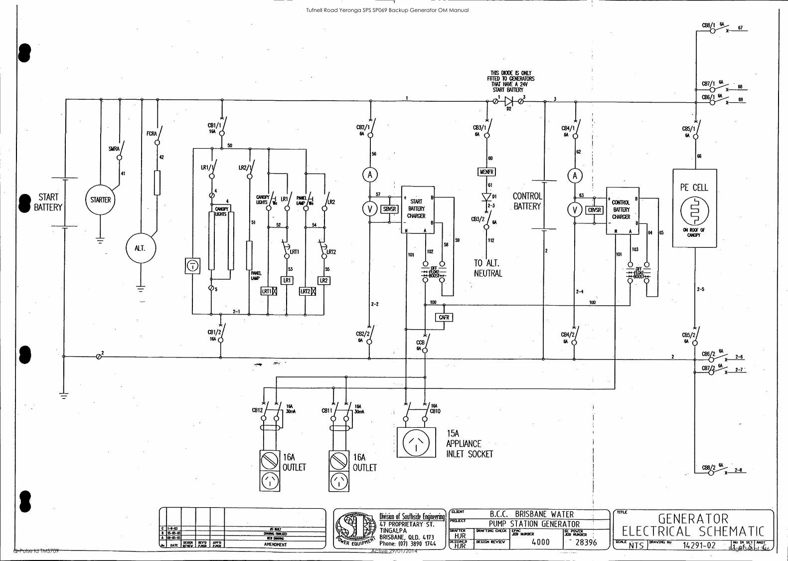
START
IP BATTERY STARTER
41
ALT.
42
LR1/
4
5
51
2-1
LR1/VW We
LRT1
LR1
16A CB2 2
64
2-2
START
BATTERY
CHARGER
101 102
0
1
THIS DIODE IS ONLY
liml) TO GENERATORS
THAT HAVE A 24V START BATTERY
033/2
112
TO ALT.
NEUTRAL
CONTROL
BATTERY
CB4/1 6A
2-4
100
CONTROL
BATTERY
CHARGER
CCB
C84/2 6A
103
64
01
L
65
Gas / 67
C137n
cevi
6A 16A CB12
1
3OrrA CM 1 30mA
1
C 1-4-03 AS till B IS-05-03 CROW MOM A 05-05-43 NCI DRIII6
Ntl. OES031
1,14_T_-11154211 REVD
_PAM APPD MGR_ AMENDMENT l
1 6A
OUTLET
Division of Southside Engineering
47 PROPRIETARY ST. TINGALPA BRISBANE, QLD. 4173 Phone: (07) 3890 1744
15A
APPLIANCE
INLET SOCKET
ta.na4T B.C.C. BRISBANE WATER
, PROJECT
PUMP STATION GENERATOR DRAFTER DRAFTING CHECK PopuisER
4000
SE MIER JOD NUMBER
- 28396 / DESIGNED
HJR DESIGN REvEy
- 2-6
2 =2
CB8614 2-8
GENERATOR ELECTRICAL SCHEMATIC
wALE NTS IDRAviNGN° 14291-02 Ir:11TIA"'C
Tufnell Road Yeronga SPS SP069 Backup Generator OM Manual
Q-Pulse Id TMS709 Active 29/01/2014 Page 340 of 346

74
0- SPEED SWITCH
LSS USS OSS
71
06 07
72
TACHOMETER
MAGNO1C
PICK-UP
I smRA1 I Fula I
VOLTAGE
REGULATOR
ELECTRONIC
GOVERNOR
SEE SHEET 5
SHUNT
TRIP PLC
CPU
C 1+03 IS RE 15-05-03 MANG FtPlEED
A 08-05-03 KW Often
DATE DESIGN REVEli _
REY9 PAGR AMENDMENT
o_o_c_r-n
1133-001
103-002
103-003
EMERGE/Cr STOP 103-004
!Air TEST
AM RESET 03-006
NMI UM 103-407
RAWL START 103-008
ANNUAL STOP 03-801
MAN TRANSFER TO VANS 103-802
14N IRINSfER TO GEN 03-803
CRANK CUTOUT
UNDER SPEED
OVER SPEED
UNDER VOLTS
OVER VOLTS
ALT. FOCH TOP.
NEN FAULT
104-P01
104-002
104403
104-004
KM-005
104-007
103
6
7
9
10
11
12
13
14
15
16
17
04-A08
CHARGER AC FARED 104-801
CONTROL BAIT. LOW VOLTS 104402
GEN CB 1RPPED
UM BAIL lOW VtTS 04-803
104
7
9
10
11
12
13
14
15
16
17
MANS FARED
----Crgt-Q)25 26 LOW Ot PRESS ROL 05-802
o_cy--6-t_027 ICH ENG 10I' SDOWN 05-803
105401
WINS ITS CLOSED 105-A02
cat An CLOSED 05403
ROOM START 05-004
REIKRE STOP
LOW OIL PRESS MOWN 05-801
offi-t28 MI ENG 1E1 WARN. 05404
LOW RAW Mil 05-805
rua
31 FUEL WIT
CANOPY DOORS OPEN
105
7
9
10
11
12
13
14
15
16
17
2-8
Division of Southside Engineering
47 PROPRIETARY ST. TINGALPA BRISBANE, QUO. 4173 Phone: 4071 3890 1744
/CLIENT B.C.C. BRISBANE WATER
PROJECT PUMP STATION GENERATOR
DRAFTER DRAFTING
aICK BUER 4000
SE O B
POWER JR NUMBER
- 28396 i DESIGNED
HJR DESIGN REVIEV
TITLE GENERATOR ELECTRICAL SCHEMATIC
SCALE NTS 1DRAviNG*3
14291-02 T'DT
Tufnell Road Yeronga SPS SP069 Backup Generator OM Manual
Q-Pulse Id TMS709 Active 29/01/2014 Page 341 of 346

1,6, 1,16
2
Q07 3
4
8
9
10
12
13
14
15
17
18
19
Q07-081 CONTROLS IN AUTO
(107402 CONTROLS IN lEST
007 -403 CORMS IN MANUAL
Q07404 ROVE START
007-105 MNNS PWLBLE
007-006 WINS CONNECTED
007407 GOMM RUNIC
c07-408 GENERATOR CONECTED
007-801 MAINS FAILED
Rd
Q07-W2 EMERGENCY STOP
Q37-1303 MEN FNJLT
007-804 LOW OIL PRES. StOWN
007-805 LOW OIL PRESS. TURNING
Q07-806 HIGH ENGINE TEMP. SUNN
007-807 HIGH Doc TEMP. am 007 -806 LOW RADIATOR LEVEL
1,6,11,16
3
Q08 4
10
12
13
14
15
17
18
19
20
008481 FUEL any
008 -102 FUEL LOW
OVERSPEED
009-404 UNTERSPEED
008-801 GENERATOR OVERLOAD
008-802 WAGER IC SUPPLY FARED
006 -803 CONTROL BATTERY LOW WILTS
008-1304 START BATTERY LOW VOLTS
008-605 CAMPY DOORS OPEN
81
1,6,11,16
2
3
Q09 4
9
10
12
13
14
17
18
19
20
C8 ALIX
SWITCH
009 -101
CLOSES WHEN
IS OFF OR
TRIPPED
0.5A 18
Q39-182 0.5A 19
Q09-0.03
009-104
009-105
Q09-086
C09-047
009-008 STARTER MOTOR RELAY
039-831 GOVERNOR CONTR0. REIM
009-1302 AUDIBLE NAM RELAY
GCR
Q09-1303 91UTDOWN AIM RELAY
MR
009-804
SEAR
0.5A 20 =a) 0.5A 21
C=3.2) 0.5A 22 =0 0.5A 23 Cfb OA 24
0-5A 41
0.5A 42
0.5A 43
Q09-935
NOT FITTED 1011E GOIRATORS
PLC
OUTPUTS
12
17
27 PIN
STATION
PLUG
2 O
3
(3) 4
(3)
(3) 5 6
(3)7 0)8
20
o)22
021
23
PLC
INPUTS
SHEET 2
2-8
13
17
14
17
015 17
016
017 17
N
E I0415-04 V PIN RIC MAE CCONIDAIS 10E ONCE" 10 1111:11 SE Ilti 0 01-00-03 AS Dill C 73-07-03 EOM MADE /MS IDE AWED
8 1545-03 OWING muse A 08-C6-03 KM MOD
N4 . DATE CESKX PAMPA
REND .__PJAIR
*MD AMENDMENT
Division of Southside Engineering
47 PROPRIETARY ST. TINGALPA BRISBANE, QLD. 4173 Phone: (07) 3890 1744
/CLIENT B.C.C. BRISBANE WATER
PRELECT PUMP STATION GENERATOR
DRAFTER
RJR DRAFTING CHECK EPAC
JIB WAGER
4000
SE ROVER AID MOTHER
- 28396 ) DESIGNED DESIGN REVEV
C1DSE MAINS ATS
CLOSE GEN ATS
GEN SHUTDOWN ALARM
GEN WARNING ALARM
LOW FUEL
GENERATOR RUNNING
GENERATOR CONNECTED
GEN CANOPY DOORS OPEN
GENERATOR IN AUTO
GENERATOR C8 OFF/TRIPPED
GENERATOR CONTROLS CONNECTED
GENERATOR CONTROLS CONNECTED
PHASE FALURE
1 MAINS ON UNE
GEN ON UNE
1
REMOTE START
REMOTE STOP
24V NEGATIVE SUPPLY
MLE GENERATOR ELECTRICAL SCHEMATIC
SCALE DRAVING No 14291-02 IT (DASEI Atel
Tufnell Road Yeronga SPS SP069 Backup Generator OM Manual
Q-Pulse Id TMS709 Active 29/01/2014 Page 342 of 346

U
433 VOLTS V
3 PHASE
50 HERTZ
ALTRNATOR
0
0
W
N
GENERATOR OUTPUT
CIRCUIT BREAKER
0( o/x 0(
R
W
B
N
E°
PLC
MODBUS
RS485
WEER COWAN
LEW PULSE CONTROL UNIT
RTIED 10 DEUTZ 912 DIES ONLT
( REFER 10 SHEET 5 )
09 e 13. . 7
D25 PLUG
5 1 9
D9 PLUG
38
104
106
104A
107
A+ ELECTREX FLASH
ET 485 S
POWER METER
109
110
111
AVSR 108
109
110
111
0101%1 1111 1111 THERMSTORS
1443 IS WU 15-0-43 EOM RIPUSED
011-115-03 113I
DATE DESIGN ARM
_ PAGR AMENDMENT
ATSR
* NOT FITTED TO
ALL ALTERNATORS 111
Division of Southside Engineering
47 PROPRIETARY ST. TINGALPA BRISBANE, QLD. 4173 Phone: (07) 3890 1744
AF1 3
6A
/wort B.C.C. BRISBANE WATER
PCT PUMP STATION GENERATOR
DRAFTER
DRAFTD"Hcar S2CHUNIER
4000
LE RIVER JIB MAGER
- 28396 _}
riliCT DESIGN REVIEV
LOAD
(TITLE
ELECTRICAL SCHEMATIC
sc'ALx NTS I DRAVING No 14291-02 PI: ,
Tufnell Road Yeronga SPS SP069 Backup Generator OM Manual
Q-Pulse Id TMS709 Active 29/01/2014 Page 343 of 346

Of)
CB7/1
GCR,c
68
82
GAC GOVERNOR,
CONTROL
UNIT.
E A
CB7/2
2-7
On PM
ACTUATOR
MAGNETIC
PICK-UP
Division of Southside Engineering
47 PROPRIETARY ST. TINGALPA BRISBANE, QLD. 4173 Phone: (07) 3890 1744
/
C 1-9-03 AS BUILT
B 15-05-03 DRAWING FINALISED
A 08-05-03 NEW DRAWING
q,,Io DATE DESIGN REVIEW
REVD P.MGR AMENDMENT /
BLit"' B.C.C. BRISBANE WATER PROJECT
PUMP STATION GENERATOR DRAFTER
HJR DRAFTING CHECK EPAC
JOB NUMBER
4000
SE POWER JOB NUMBER
28396 i DESIGNED
HJR DESIGN REVIEW
(-TITLE
GAC GOVERNOR CC\TROLS
SCALE
NTS DRAWING No 14291-02 No IN SET
5 of 5 AMDT
c,/
Tufnell Road Yeronga SPS SP069 Backup Generator OM Manual
Q-Pulse Id TMS709 Active 29/01/2014 Page 344 of 346

CB7/1
68
GCfg
82
TO ELECTREX
FLASH METER
(SHEET 4)
104A
FROM RED PHASE
CURRENT TRANSFORMER
(SHEET 4)
104
BARBER COLMAN
LOAD PULSE CONTROL
4 5
13
BARBER COLMAN
GOVERNOR
CONTROL UNIT
12 1 2 5 4 3
10
11
CB7/2
2-7
032 033
ACTUATOR
MAGNETIC
PICK-UP
Division of Southside Engineering
47 PROPRIETARY ST. TINGALPA BRISBANE, GILD. 4173 Phone: (07) 3890 1744
0 1-9-03 AS BUILT
C 14-06-03 LOAD PULSE CONTROL UNif WAS ADDED
B 15-05-03 DRAWING FINALISED
A 08-05-03 NEW DRAWING
..'41) DATE DESIGN REVIEW
REVD R.MGR AMENDMENT .1
' l.LICII I
B.L.C. BRISBANE WA1 ER PROJECT
PUMP STATION GENERATOR DRAFTER
HJR DRAFTING CHECK EPAC
JOB NUMBER SE POWER JOB NUMBER
28396 DESIGNED
HJR DESIGN REVIEW 4000
CMLE
BARBER COLvA\ GOVER\OR CO\TROLS
SCALE
N T S DRAWING No
14291-02 No IN SET
5 of 5._
AMDT
Di
Tufnell Road Yeronga SPS SP069 Backup Generator OM Manual
Q-Pulse Id TMS709 Active 29/01/2014 Page 345 of 346

O.
CB7/1
GCR
RADIATOR
LEVEL
INTERPOSING
RELAY
TO SHEET
2 of 5
44 I 105-B05
2-8
29
68 83
8
83
RUN /DIAGNOSE
PROGRAM SWITCH 84
GOVERNOR
FAULT
2-7
PLUG
M'
X1
DEUTZ EvR
GOVERNOR
CONTROL UNIT
14 1
17 15
PLUG
105-B01
105-B03
DIAGNOSTIC PLUG
2-7
25
0 27
SHEET 2 of 5
0
REFER TO DEUTZ
MANUAL FOR DETAILS
CB7/2
ENGINE (MOTOR) ANCILLARIES
Division of Southside Engineering
47 PROPRIETARY ST. TINGALPA BRISBANE, 0.LD. 4173 Phone: (07) 3890 1744
/..
D 1-9-03 AS BUILT
C 15-08-03 RADIATOR LEVEL INTERPOSING REIM WAS ADDED
B 15-05-03 DRAWING FlNALJSED
A 08-05-03 NEW DRAWING
..? DATE DESIGN REVIEW
REVD P.MGR AMENDMENT
.1
L.L.ACII I
B.L.L. BRISBANE WA I ER PROJECT
PUMP STATION GENERATOR DRAFTER
HJR DRAFTING CHECK EPAC
JOB NUMBER SE POWER JOB NUMBER
28396 ../
DESIGNED
HJR DESIGN REVIEW 4000
'TITLE
DEUTZ
GOVER\OR CO EV R
TROLS SCALE
N T S DRAWING No 14291-02 No IN SET
4 of 5 mu
D
Tufnell Road Yeronga SPS SP069 Backup Generator OM Manual
Q-Pulse Id TMS709 Active 29/01/2014 Page 346 of 346