turner 2nd year - transparencies
TRANSCRIPT

Turner 2nd Year − Transparencies


Table of ContentsTurner 2nd Year − Transparencies..................................................................................................................1
MEASUREMENT OF TAPER ANGLE USING SINEBAR......................................................................1TAPER CALCULATION USING SINEBAR............................................................................................2TURRET LATHE (PARTS AND FUNCTION).........................................................................................3TURRET AND CAPSTAN LATHE (COMPARISON)..............................................................................4TURRET LATHE TOOL SETUP (EXTERNAL TURNING).....................................................................5TURRET LATHE (EXTERNAL TURNING SEQUENCE)........................................................................6SELF OPENING DIE−HEAD (WORKING PRINCIPLE).........................................................................7BAR FEEDING MECHANISM (FUNCTION)..........................................................................................8TURRET LATHE TOOL SETUP (INTERNAL TURNING)......................................................................9TURRET LATHE (INTERNAL TURNING SEQUENCE).......................................................................11AIR−OPERATED CHUCK (WORKING PRINCIPLE)...........................................................................12COLLET − DRAW−IN−TYPE (WORKING PRINCIPLE)......................................................................13COLLET − PUSH OUT TYPE (WORKING PRINCIPLE)......................................................................14COLLET − DEAD LENGTH TYPE (WORKING PRINCIPLE)...............................................................15COPY TURNING ATTACHMENT (WORKING PRINCIPLE)................................................................15LEADING AND FOLLOWING ANGLES (SQUARE THREADING TOOL)............................................16LEADING AND FOLLOWING ANGLES (ASSIGNMENT)....................................................................17TAPER TURNING ATTACHMENT − YOKE TYPE (PRINCIPLE)........................................................18TAPER TURNING ATTACHMENT − TELESCOPIC TYPE.................................................................19DOUBLE START THREAD (CATCH PLATE METHOD)......................................................................20DOUBLE START THREAD (DIVIDING THE GEAR METHOD)...........................................................21DOUBLE START THREAD (GRADUATED COLLAR METHOD)........................................................22THREAD CUTTING BY HALF ANGLE METHOD (PRINCIPLE)..........................................................23
i

ii

Turner 2nd Year − Transparencies
CENTRAL INSTRUCTIONALMEDIA INSTITUTE, MADRAS
ANINDO − GERMAN PROJECT
Directorate General of Employment & Training, Ministry of Labour, Govt. of India
Developed byCENTRAL INSTITUTIONAL MEDIA INSTITUTE
in collaboration with DEUTSCHE GESELLSCHAFT FEUR TECHNISCHE ZUSAMMENARBEIT (GTZ)Germany
P.O. Box 3142, 76, GST Road, Guindy, Madras − 600 032. Phone: 234 5256, 234 5257, Fax: (0091−44) 2342791
MEASUREMENT OF TAPER ANGLE USING SINEBAR
TR 01 02 10 01 95
To calculate the angle of taper formed on a round rod, the job (1) is placed on sine bar (2). One end of thesine bar (i.e. smaller dia. end on job) is lifted up and slip gauges (3) are placed in between sine bar roller andthe surface plate. The top surface of the taper portion should be brought to perfect horizontal line by placingadditional slip gauges, and testing with dial test indicator (4). A right angled triangle is formed, with the slipgauge height as opposite side (B) and the length of sine bar as hypotenuse (A). By applying thetrigonometrical ratio formula,
, we get sine ? value in degrees i.e. the included angle of the tapered job.
1

TAPER CALCULATION USING SINEBAR
TR 01 02 10 02 95
1.
Therefore B = 68.404.
2.
Therefore ? = 23°34’ 41”
3.
Therefore B = 84.524
4.
Therefore ? = 30°
2

TURRET LATHE (PARTS AND FUNCTION)
TR 01 12 02 01 95
1. Head stock Speed changing gears and spindle are housed in the head stock.
2. Spindle Collets and chucks are mounted on the spindle for work holding.
3. Square tool post Four different tools can be set at a time.
4. Rear tool post Parting−off tool can be set in this tool post in inverted position.
5. Turret head The turret head has six faces and can hold six different tools.
6. Main bed Carriage and the turret head slide, over the bed.
7. Handwheel for the longitudinalmotion of turret
Moves the turret head along the bed.
8. Cross slide hand wheel Moves the cross slide to give depth of cut.
9. Carriage hand wheel Moves the carriage along the bed.
10. Feed drive for turret Knob for turret automatic feed.
11. Feed drive for cross slide Knob for cross−slide automatic feed.
3

12. Feed gear box This will have a number of gears and provide different feed rates forlongitudinal and crosswise movements.
13. Spindle speed Different spindle speeds can be obtained by rotating the selector todifferent positions.
TURRET AND CAPSTAN LATHE (COMPARISON)
TR 01 12 02 02 95
TURRET LATHE
CAPSTAN LATHE
1. Both the lathes are used for mass production work.
2. Turret lathe is a heavy duty machine and Capstan lathe is a light duty machine.
3. In a turret lathe the turret head (1) is directly mounted on the main bed (2).
4. In a capstan lathe the turret head (1) is mounted on an additional slide (4).
5. In a turret lathe the turret head (1) can be moved over the main bed (2) from one end to the other end.
6. In a capstan lathe, the turret head (1) can be moved over the additional slide (4) within its limitations.
4

TURRET LATHE TOOL SETUP (EXTERNAL TURNING)
TR 01 12 02 03 95
TOOLING SEQUENCE
1. Bar stop2. Step turning3. Centre drilling4. Taper (Form turning)5. Shoulder facing
Note: To be discussed along with the
TransparenciesNo. TR 01 12 02 04 95TR 01 12 02 05 95
Work centre is supported during machining steps
4 5 6
OPERATIONS ON THE COMPONENT
A Parting−offB O.D. TurningC Form turningD Thread cuttingE ChamferingF Facing
5

G Facing
TURRET LATHE (EXTERNAL TURNING SEQUENCE)
TR 01 12 02 04 95
1. Bar stop2. Step turning3. Centre drilling4. Centre support and forming taper5. Centre support and shoulder facing
TR 01 12 02 05 95
6

6. Centre support and O.D. turning7. Chamfering8. Threading9. Parting off10. Forming end
SELF OPENING DIE−HEAD (WORKING PRINCIPLE)
TR 01 12 02 06 95
7

After setting the required size of chasers (1) in the die head (2), it is initially fed to the work by the operator.Then it is feeds itself along the work and follows with the turret (3). The turret stopper is set slightly short ofthe thread length.
When the turret movement is stopped by its stopper, the die head (2) continues to move forward under selffeeding action.
When there is no further movement for the die head, an inside trip triggers off, the detent pin (4) goes intoaction, the closing handle (5) falls to the side and the die opens. The die head is taken out without stoppingthe machine.
Note: The chasers are numbered as 1,2,3 and 4.
BAR FEEDING MECHANISM (FUNCTION)
TR 01 12 02 07 95
8
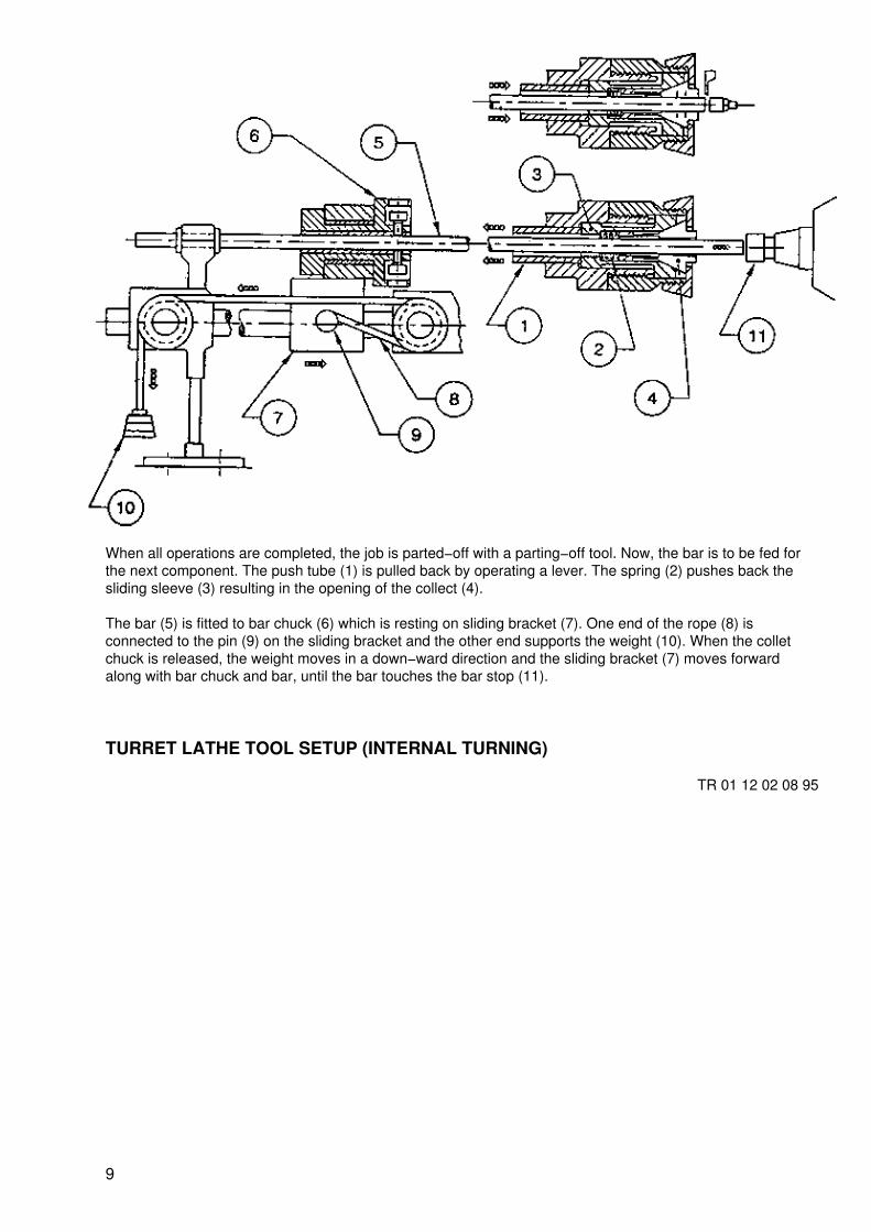
When all operations are completed, the job is parted−off with a parting−off tool. Now, the bar is to be fed forthe next component. The push tube (1) is pulled back by operating a lever. The spring (2) pushes back thesliding sleeve (3) resulting in the opening of the collect (4).
The bar (5) is fitted to bar chuck (6) which is resting on sliding bracket (7). One end of the rope (8) isconnected to the pin (9) on the sliding bracket and the other end supports the weight (10). When the colletchuck is released, the weight moves in a down−ward direction and the sliding bracket (7) moves forwardalong with bar chuck and bar, until the bar touches the bar stop (11).
TURRET LATHE TOOL SETUP (INTERNAL TURNING)
TR 01 12 02 08 95
9

TOOLING SEQUENCE
1 Facing 5 Counterboring
2 O.D. Turning 6 Recessing
3 Spotting (drill) 7 Threading(Tap)
4 Drilling 8 Parting−off
Note: To be discussed along with the
TransparenciesNo. TR 01 12 02 09 95TR 01 12 02 10 95
OPERATIONS ON THE COMPONENT
A FacingB O.D. TurningC DrillingD BoringE RecessingF ThreadingG Parting−off
10

TURRET LATHE (INTERNAL TURNING SEQUENCE)
TR 01 12 02 09 95
1. Bar stop2. Facing3. O.D. Turning4. Start drill (spotting)5. Drilling
TR 01 12 02 10 95
11

6. Counter boring7. Recessing8. Threading with tap9. Parting−off
AIR−OPERATED CHUCK (WORKING PRINCIPLE)
TR 01 13 01 03 95
12
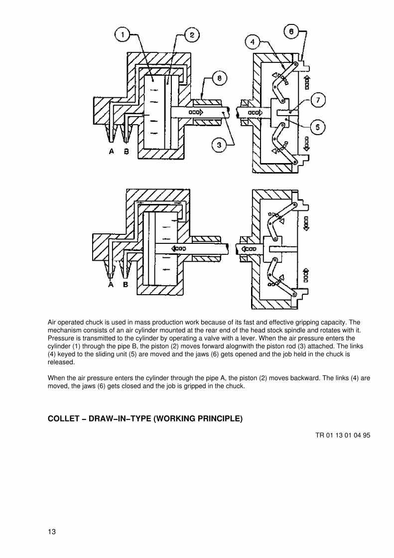
Air operated chuck is used in mass production work because of its fast and effective gripping capacity. Themechanism consists of an air cylinder mounted at the rear end of the head stock spindle and rotates with it.Pressure is transmitted to the cylinder by operating a valve with a lever. When the air pressure enters thecylinder (1) through the pipe B, the piston (2) moves forward alognwith the piston rod (3) attached. The links(4) keyed to the sliding unit (5) are moved and the jaws (6) gets opened and the job held in the chuck isreleased.
When the air pressure enters the cylinder through the pipe A, the piston (2) moves backward. The links (4) aremoved, the jaws (6) gets closed and the job is gripped in the chuck.
COLLET − DRAW−IN−TYPE (WORKING PRINCIPLE)
TR 01 13 01 04 95
13
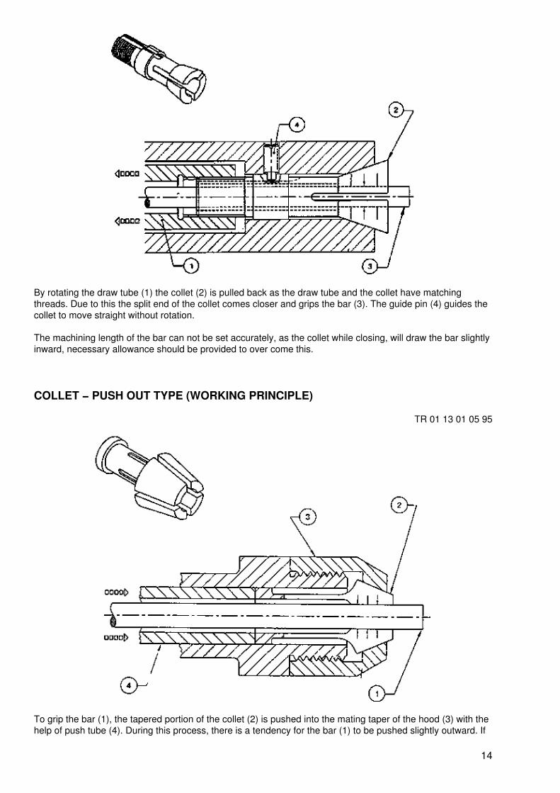
By rotating the draw tube (1) the collet (2) is pulled back as the draw tube and the collet have matchingthreads. Due to this the split end of the collet comes closer and grips the bar (3). The guide pin (4) guides thecollet to move straight without rotation.
The machining length of the bar can not be set accurately, as the collet while closing, will draw the bar slightlyinward, necessary allowance should be provided to over come this.
COLLET − PUSH OUT TYPE (WORKING PRINCIPLE)
TR 01 13 01 05 95
To grip the bar (1), the tapered portion of the collet (2) is pushed into the mating taper of the hood (3) with thehelp of push tube (4). During this process, there is a tendency for the bar (1) to be pushed slightly outward. If
14

the bar is fed against a bar stop fitted on the turret head, it will ensure accurate setting of the length formachining.
COLLET − DEAD LENGTH TYPE (WORKING PRINCIPLE)
TR 01 13 01 06 95
This collet can accurately position the bar to the required length. When the push tube (1) pushes the slidingsleeve (2) forward towards the taper portion of the collet (3), the split end comes closer and grips the bar (4).The shoulder stop of the hood (5) will not allow any end movement for the collet (3) as well as the bar (4).
COPY TURNING ATTACHMENT (WORKING PRINCIPLE)
TR 01 13 01 03 95
15

PRINCIPLE
The copying attachment is functioning with the help of hydraulic system. The cutting tool (1 a) and the stylus(2) are connected to an angle shaped piece which is linked to a hydraulic system. The movement of the stylusis guided by the profile of a template(3).
FUNCTION
On the lathe the job (4) is held between centres. A master piece (5) of the job to be produced is heldseparately parallel to the job axis. The cutting tool (1 b) is held up−side down in the rear tool post which islinked to a stylus (2).
When the automatic feed is engaged, the stylus (2) moves from tail stock to head stock with a forwardpressure. The movement of the stylus (2) is guided by the profile of the master piece (5).
LEADING AND FOLLOWING ANGLES (SQUARE THREADING TOOL)
TR 01 14 02 01 95
16
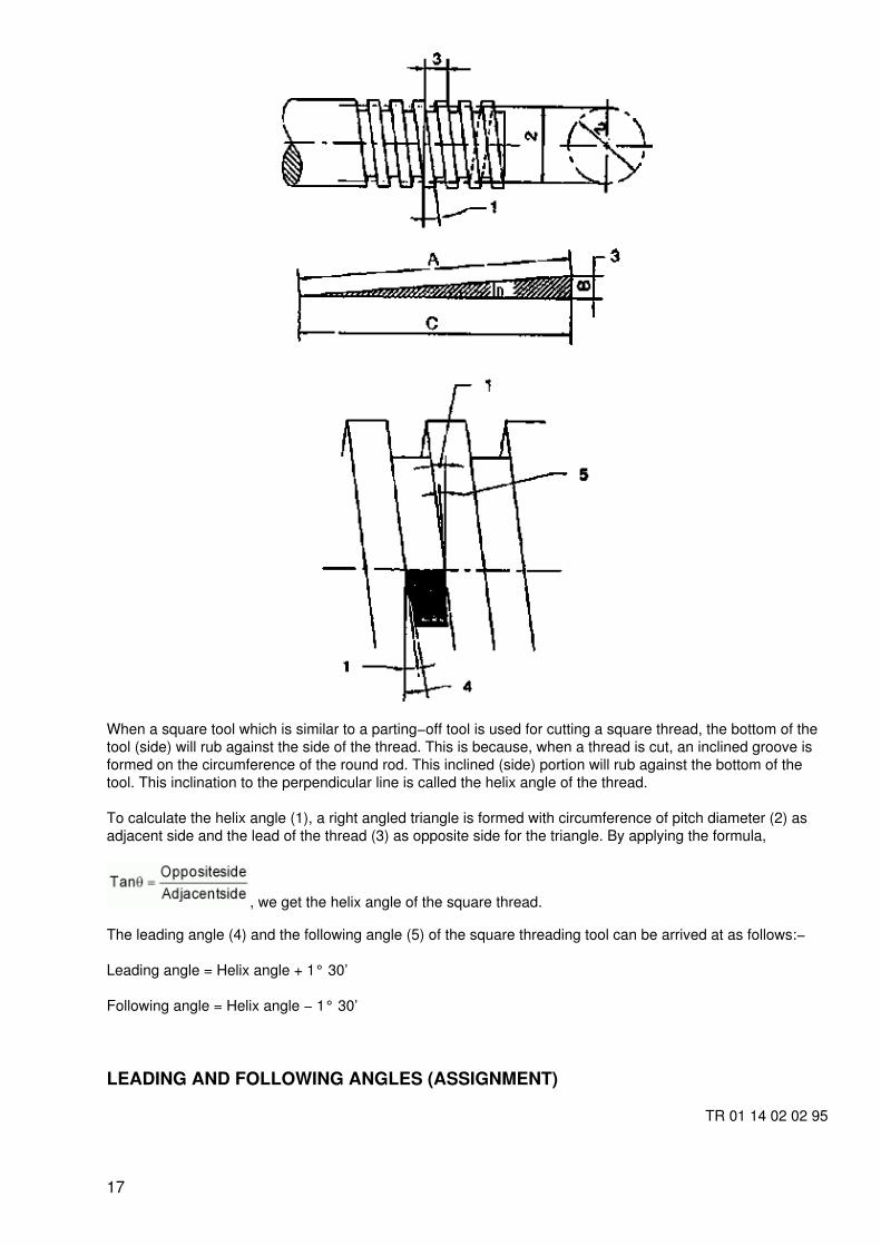
When a square tool which is similar to a parting−off tool is used for cutting a square thread, the bottom of thetool (side) will rub against the side of the thread. This is because, when a thread is cut, an inclined groove isformed on the circumference of the round rod. This inclined (side) portion will rub against the bottom of thetool. This inclination to the perpendicular line is called the helix angle of the thread.
To calculate the helix angle (1), a right angled triangle is formed with circumference of pitch diameter (2) asadjacent side and the lead of the thread (3) as opposite side for the triangle. By applying the formula,
, we get the helix angle of the square thread.
The leading angle (4) and the following angle (5) of the square threading tool can be arrived at as follows:−
Leading angle = Helix angle + 1° 30’
Following angle = Helix angle − 1° 30’
LEADING AND FOLLOWING ANGLES (ASSIGNMENT)
TR 01 14 02 02 95
17

Helix angle = 4°2’Leading angle = 4°2’ + 1°30’ = 5°32’Following angle = 4°2’−1°30’ = 2°32’
Helix angle = 4°2’Leading angle = 4°2’ + 1°30’ = 5°32’Following angle = 4°2’−1°30’ = 2°32’
Helix angle = 3°18’Leading angle = 3°18’ + 1°30’ = 4°48’Following angle = 3° 18’−1°30’ = 1 °48’
Helix angle = 3°15’Leading angle = 3°15’ + 1°30’ = 4°45’Following angle = 3°15’ − 1°30’ = 1°45’
TAPER TURNING ATTACHMENT − YOKE TYPE (PRINCIPLE)
TR 01 15 03 04 95
18

In the normal working condition the cross slide (1) is moved forward and backward with the rotation of a screwrod (2) which is linked to a box nut (3). The guide bar (4) is set to an angle equal to the angle of taper on job(5). The taper attachment is centrally located to cover the length of taper on job. The screw (6) is removed tode−link the box nut. The cross−slide is linked to the taper attachment by tightening the binding screw handle(7). When the machine is started with automatic feed on, the tool (10) will move in an inclined direction equalto the angle set on guide bar (4). The compound rest (8) is tilted perpendicular to the job axis to give depth ofcut.
TAPER TURNING ATTACHMENT − TELESCOPIC TYPE
TR 01 15 03 05 95
19

The screw rod (1) is linked to cross slide (2) through a box nut (3) and screw (4). One end of the cross slide isconnected to the taper attachment with a binding screw (5) and the other end the cross slide handle isassembled with a spline (6 & 7 − hole and shaft). The guide bar (8) is set to an angle equal to the angle oftaper on job (9). The taper attachment is centrally located to cover the length of taper on job.
After locking the cross slide to the taper attachment, the machine is switched on to give automatic feed. Thetool will move in an inclined direction equal to the angle set on guide bar (8). In this case, there is no need toremove the screw (4) and de−link the box nut, because, for the movement of the cross slide screw rod andhandle are assembled with a spline construction (6 & 7) one end of the screw rod is connected to the guidebar assembly. Depth of cut can be given by the cross slide.
DOUBLE START THREAD (CATCH PLATE METHOD)
TR 01 15 04 01 95
20

A catch plate (1) with two slots in the opposite sides (180° apart) is mounted on the lathe. Job (2) is heldbetween centres accommodating the tail of the carrier (3) in slot No.1. Calculate the lead of the thread and cutthe 1st start to the required depth.
Stop the machine and remove the job along with the dog carrier. Re−set the job accommodating the tail of thecarrier in slot No.2. Now, the tool will come exactly in the middle of the two grooves. Cut the 2nd start of thethread.
Note: The two slots formed on the catch plate in the opposite sides (180° apart) are marked as 1 and 2.
DOUBLE START THREAD (DIVIDING THE GEAR METHOD)
TR 01 15 04 02 95
21

The gear train should be such that the gear teeth in the driver gear (1) must be divisible by two. Calculate thelead of the thread and cut the 1st start to the required depth. Then stop the lathe. Open the rear guard. Markthe driver gear (1) teeth into two so that there are equal number of teeth on either sides. One at the bottomwhere driver gear (1) meshes with intermediate gear (2). The other is exactly on the opposite side.
Make another chalk mark between two gears where intermediate gear (2) and lead screw gear (driven) (3)meshes.
Remove the intermediate gear (2) and rotate the driver gear (1) exactly half turn. While doing this the job alsorotates half turn. Re−fix the intermediate gear so that the chalk marks matches. Now, the tool (4) will comeexactly in the middle of the two grooves of the 1st thread.
DOUBLE START THREAD (GRADUATED COLLAR METHOD)
TR 01 15 04 03 95
22

Calculate the lead of the thread. Arrange gear train and cut the 1st start of the thread to the required depth.Stop the machine and move the compound slide (1) forward to the half the lead of the thread. For this, usegraduated collar of the compound rest. Now, the tool will come exactly in the middle of the two grooves of the1st thread. Cut the 2nd start.
THREAD CUTTING BY HALF ANGLE METHOD (PRINCIPLE)
TR 01 15 04 04 95
23
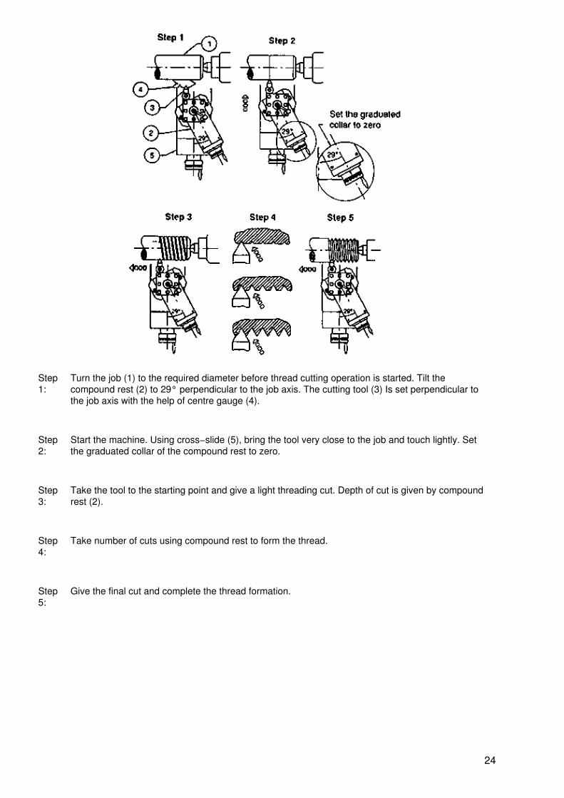
Step1:
Turn the job (1) to the required diameter before thread cutting operation is started. Tilt thecompound rest (2) to 29° perpendicular to the job axis. The cutting tool (3) Is set perpendicular tothe job axis with the help of centre gauge (4).
Step2:
Start the machine. Using cross−slide (5), bring the tool very close to the job and touch lightly. Setthe graduated collar of the compound rest to zero.
Step3:
Take the tool to the starting point and give a light threading cut. Depth of cut is given by compoundrest (2).
Step4:
Take number of cuts using compound rest to form the thread.
Step5:
Give the final cut and complete the thread formation.
24