twn · twn ventilo-convecteurs fan coil units ventiloconvettore ventilo-convectores...
TRANSCRIPT
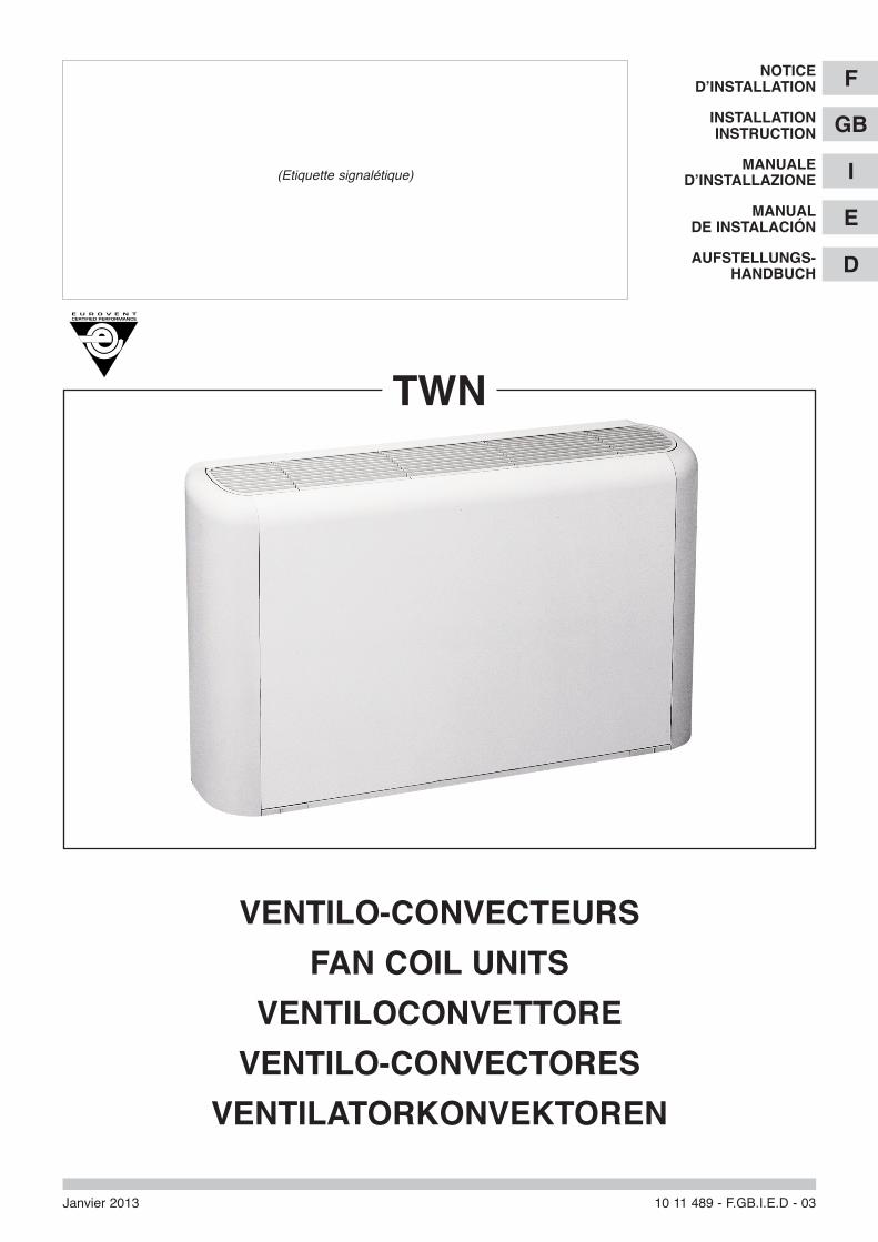
tWN
VeNtiLo-coNVecteURs
faN coiL UNits
VeNtiLocoNVettoRe
VeNtiLo-coNVectoRes
VeNtiLatoRKoNVeKtoReN
Janvier 2013 10 11 489 - F.GB.I.E.D - 03
(Etiquette signalétique)
f
gb
i
e
d
Notice d’iNstaLLatioN
iNstaLLatioN iNstRUctioN
MaNUaLe d’iNstaLLaZioNe
MaNUaL de iNstaLacióN
aUfsteLLUNgs-haNdbUch
GB
2
CONTENTS
1 - General . . . . . . . . . . . . . . . . . . . . . . . . . . . . . . . . . . . . . . . . . . . . .22 - Installation . . . . . . . . . . . . . . . . . . . . . . . . . . . . . . . . . . . . . . . . . . .33 - Connections . . . . . . . . . . . . . . . . . . . . . . . . . . . . . . . . . . . . . . . . . .54 - Starting . . . . . . . . . . . . . . . . . . . . . . . . . . . . . . . . . . . . . . . . . . . . .115 - Maintenance instructions . . . . . . . . . . . . . . . . . . . . . . . . . . . . . . .126 - Internal wiring diagram . . . . . . . . . . . . . . . . . . . . . . . . . . . . . . . . .12
1 - GENERAL
1.1 - FOREWORD• The equipment must be installed, started-up and maintained by authorised and qualified personnel, in accordance with local
rules and professional standards.
• Non-compliance with these rules, or the undertaking of product modification without prior approval by TECHNIBEL, will leadto suspension of the guarantee.
1.2 - GENERAL SUPPLY CONDITIONS• Generally speaking, the material is transported at the consignee's risk.
• The consignee must immediately provide the carrier with written reserves if he finds any damage caused during transport.
• Do not place objects on the unit.
1.3 - STORAGE• The fan coil unit should remain in its original packaging prior to installation: minimum storage temperature: -20° C.
1.4 - vOLTAGE• Before any operation, check that the voltage and frequency on the appliance rating plate correspond with those of the mains
supply.
1.5 - CHECKS BEFORE INSTALLATION• The evacuation of condensates is carried out by gravity.
• To ensure the removal of condensate by gravity, the appliance must be assembled horizontally or slightly tilted towards theoutlet side (see paragraph 3.3).
• The fan speed switches can only be connected to a single appliance.
• All the motors supplied have been tested in the factory. Incorrect connection at the place of assembly may damage themotor.
• For the installation and operation of accessories, refer to the technical documentation furnished with the accessories andthe TWN technical manual.
1.6 - DESCRIPTION OF APPLIANCES• See Technical Instructions.
1.7 - USE OF EqUIPMENT• This equipment is intented for the air-conditioning of premises and to provide comfort for the personnel.
MARKING
This product marked conforms to the essential requirements of the Directives:
- Low voltage no. 2006/95/EC.
- Electromagnetic Compatibility no. 2004/108/EC.
This appliance is not designed to be used by people (including children) whose physical, sensoryor mental capacities are impaired, or who lack experience or knowledge, unless they are supervisedor have received instructions on how to use the appliance by a person who is responsible for theirsafety. Children must be supervised to ensure that they do not play with the appliance or itsaccessories.
IMPORTANT
GB
3
1.8 - PRECAUTIONS• Hydraulic circuit:
- Minimum water inlet temperature: 5°C.- Maximum water inlet temperature:
• main battery: 60°C,• additional battery: 90°C.
Note: For reasons relating to comfort (homogeneity of the air temperature in the room), not exceeding a water inlettemperature of 55°C in the main batter is recommended.
- Maximum operating pressure: 10 bar.
• Ambient air:- Minimum air recirculation temperature: 5°C,- Maximum air recirculation temperature: 32°C.
Important: During installation shut-down, in case of connection to an outside air vent or in case of ambient temperaturenear 0°C, there is a risk that the hoses may freeze. Envisage draining the hydraulic circuit.
1.9 - MODELS• 21 models (broken down into 7 models horizontal and vertical units with housing or built-in units without housing):
- 2-tube or 4-tube versions (with additional battery),- 2-tube Cooling + 2 wires (with electric heater element), except model 11.
2 - INSTALLATION
2.1 - PRELIMINARY CHECKS• As accessories are not factory-installed, we recommended to mount
them on before the unit is installed. Refer to the corresponding technicalmanuals.
• The standard hydraulic connection is located on the left-hand side (facingthe unit, vertical installation).
The connection may be changed on site. To make the necessarymodifications, proceed as follows:
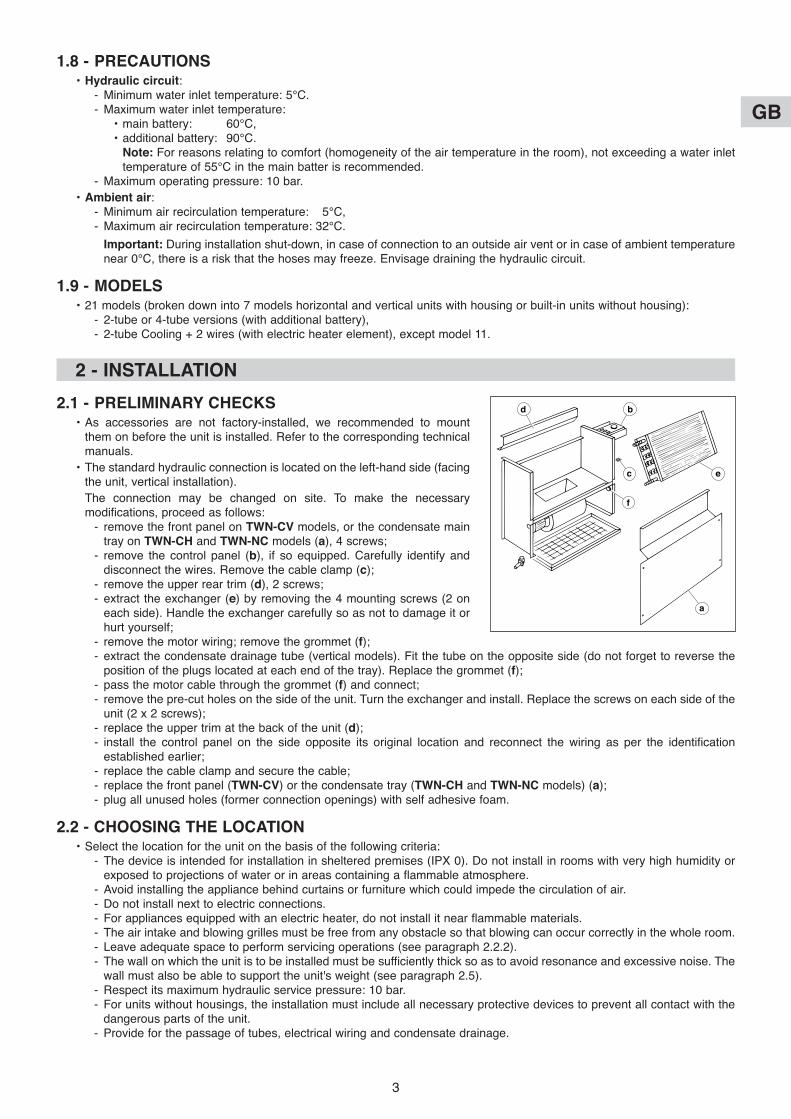
- remove the front panel on TWN-Cv models, or the condensate maintray on TWN-CH and TWN-NC models (a), 4 screws;
- remove the control panel (b), if so equipped. Carefully identify anddisconnect the wires. Remove the cable clamp (c);
- remove the upper rear trim (d), 2 screws;- extract the exchanger (e) by removing the 4 mounting screws (2 on
each side). Handle the exchanger carefully so as not to damage it orhurt yourself;
- remove the motor wiring; remove the grommet (f);- extract the condensate drainage tube (vertical models). Fit the tube on the opposite side (do not forget to reverse the
position of the plugs located at each end of the tray). Replace the grommet (f);- pass the motor cable through the grommet (f) and connect;- remove the pre-cut holes on the side of the unit. Turn the exchanger and install. Replace the screws on each side of the
unit (2 x 2 screws);- replace the upper trim at the back of the unit (d);- install the control panel on the side opposite its original location and reconnect the wiring as per the identification
established earlier;- replace the cable clamp and secure the cable;- replace the front panel (TWN-Cv) or the condensate tray (TWN-CH and TWN-NC models) (a);- plug all unused holes (former connection openings) with self adhesive foam.
2.2 - CHOOSING THE LOCATION• Select the location for the unit on the basis of the following criteria:
- The device is intended for installation in sheltered premises (IPX 0). Do not install in rooms with very high humidity orexposed to projections of water or in areas containing a flammable atmosphere.
- Avoid installing the appliance behind curtains or furniture which could impede the circulation of air.- Do not install next to electric connections.- For appliances equipped with an electric heater, do not install it near flammable materials.- The air intake and blowing grilles must be free from any obstacle so that blowing can occur correctly in the whole room.- Leave adequate space to perform servicing operations (see paragraph 2.2.2).- The wall on which the unit is to be installed must be sufficiently thick so as to avoid resonance and excessive noise. The
wall must also be able to support the unit's weight (see paragraph 2.5).- Respect its maximum hydraulic service pressure: 10 bar.- For units without housings, the installation must include all necessary protective devices to prevent all contact with the
dangerous parts of the unit.- Provide for the passage of tubes, electrical wiring and condensate drainage.
b
c
a
e
d
f
GB
4
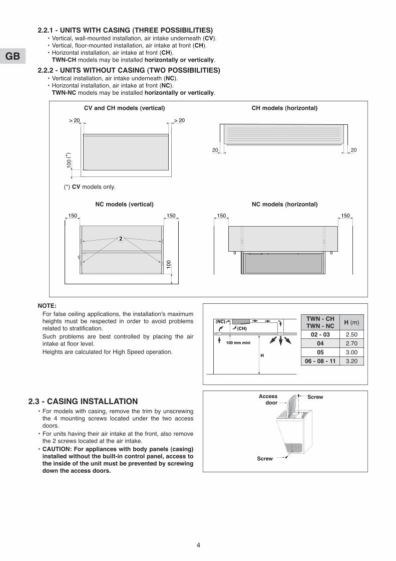
2.2.1 - UNITS WITH CASING (THREE POSSIBILITIES)• Vertical, wall-mounted installation, air intake underneath (Cv).• Vertical, floor-mounted installation, air intake at front (CH).• Horizontal installation, air intake at front (CH).
TWN-CH models may be installed horizontally or vertically.
2.2.2 - UNITS WITHOUT CASING (TWO POSSIBILITIES)• Vertical installation, air intake underneath (NC).• Horizontal installation, air intake at front (NC).
TWN-NC models may be installed horizontally or vertically.
��������
����
����������
(*)
100
> 20> 20
Cv and CH models (vertical)
�����������
�����
2
150 150
100
NC models (vertical)
����
����
150 150
NC models (horizontal)
��������������
���
���
2020
CH models (horizontal)
(*) Cv models only.
NOTE:
For false ceiling applications, the installation's maximumheights must be respected in order to avoid problemsrelated to stratification.
Such problems are best controlled by placing the airintake at floor level.
Heights are calculated for High Speed operation.
2.3 - CASING INSTALLATION• For models with casing, remove the trim by unscrewing
the 4 mounting screws located under the two accessdoors.
• For units having their air intake at the front, also removethe 2 screws located at the air intake.
• CAUTION: For appliances with body panels (casing)installed without the built-in control panel, access tothe inside of the unit must be prevented by screwingdown the access doors.
������������������
H
100 mm mini
(NC)
(CH)
TWN - CHTWN - NC
H (m)
02 - 03 2.50
04 2.70
05 3.00
06 - 08 - 11 3.20
ScrewAccessdoor
Screw
GB
5
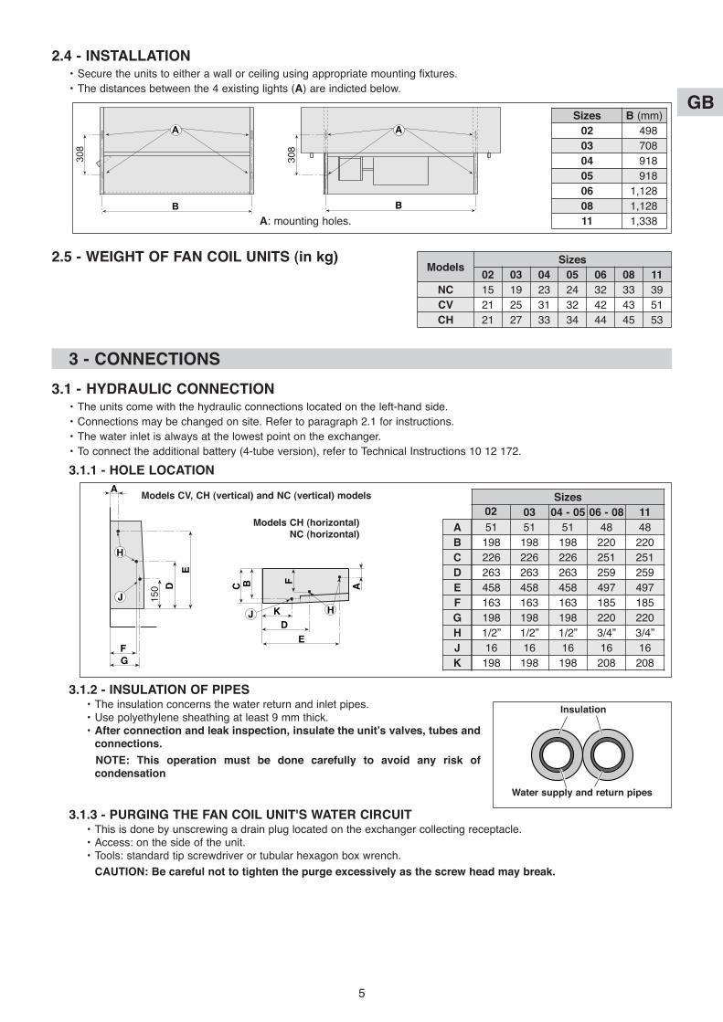
2.4 - INSTALLATION• Secure the units to either a wall or ceiling using appropriate mounting fixtures.
• The distances between the 4 existing lights (A) are indicted below.
2.5 - WEIGHT OF FAN COIL UNITS (in kg)
308
A
B
308
A
B
A: mounting holes.
Sizes B (mm)
02 498
03 708
04 918
05 918
06 1,128
08 1,128
11 1,338
ModelsSizes
02 03 04 05 06 08 11
NC 15 19 23 24 32 33 39
Cv 21 25 31 32 42 43 51
CH 21 27 33 34 44 45 53
3 - CONNECTIONS
3.1 - HYDRAULIC CONNECTION• The units come with the hydraulic connections located on the left-hand side.
• Connections may be changed on site. Refer to paragraph 2.1 for instructions.
• The water inlet is always at the lowest point on the exchanger.
• To connect the additional battery (4-tube version), refer to Technical Instructions 10 12 172.
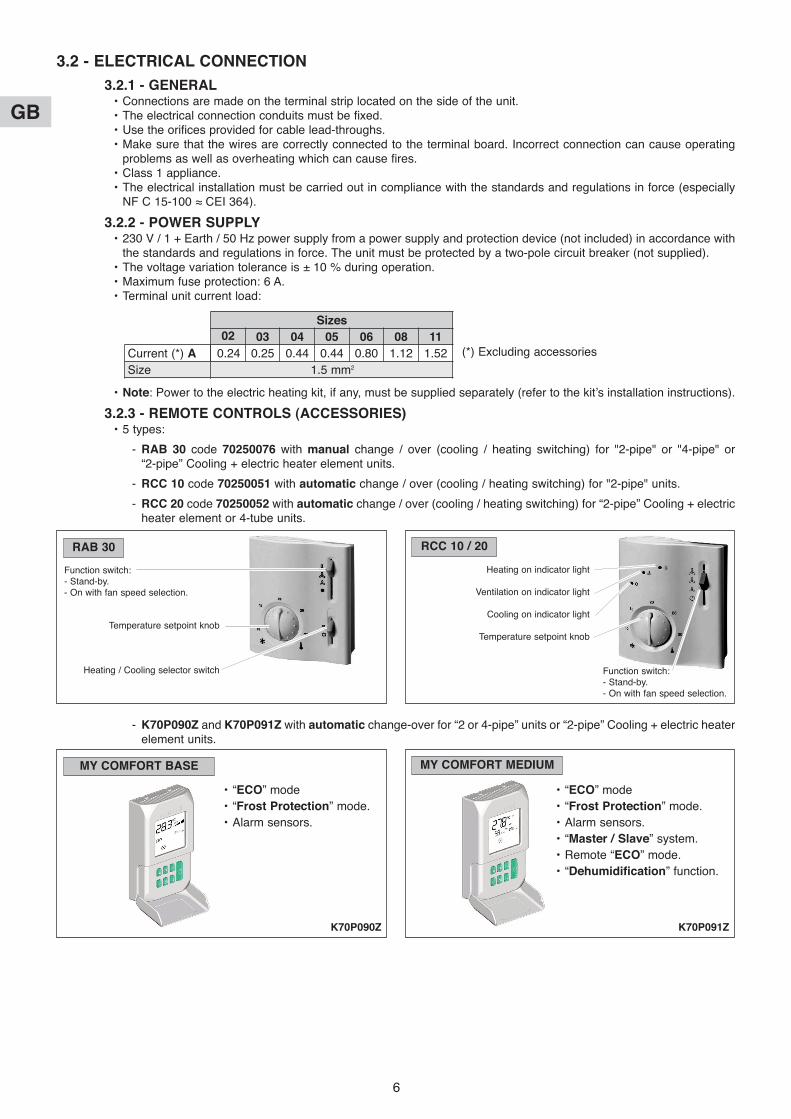
3.1.1 - HOLE LOCATION
3.1.2 - INSULATION OF PIPES• The insulation concerns the water return and inlet pipes.• Use polyethylene sheathing at least 9 mm thick.• After connection and leak inspection, insulate the unit’s valves, tubes and
connections.
NOTE: This operation must be done carefully to avoid any risk ofcondensation
3.1.3 - PURGING THE FAN COIL UNIT'S WATER CIRCUIT• This is done by unscrewing a drain plug located on the exchanger collecting receptacle.• Access: on the side of the unit.• Tools: standard tip screwdriver or tubular hexagon box wrench.
CAUTION: Be careful not to tighten the purge excessively as the screw head may break.
������������
150
A
H
D
E
F
G
J
���
C B A
F
K
DJ H
E
Models Cv, CH (vertical) and NC (vertical) models
Models CH (horizontal)NC (horizontal)
Sizes
02 03 04 - 05 06 - 08 11
51 51 51 48 48
198 198 198 220 220
226 226 226 251 251
263 263 263 259 259
458 458 458 497 497
163 163 163 185 185
198 198 198 220 220
1/2” 1/2” 1/2” 3/4” 3/4”
16 16 16 16 16
198 198 198 208 208
A
B
C
D
E
F
G
H
J
K
Insulation
Water supply and return pipes
GB
6
3.2 - ELECTRICAL CONNECTION
3.2.1 - GENERAL• Connections are made on the terminal strip located on the side of the unit.• The electrical connection conduits must be fixed.• Use the orifices provided for cable lead-throughs.• Make sure that the wires are correctly connected to the terminal board. Incorrect connection can cause operating
problems as well as overheating which can cause fires.• Class 1 appliance.• The electrical installation must be carried out in compliance with the standards and regulations in force (especially
NF C 15-100 ≈ CEI 364).
3.2.2 - POWER SUPPLY• 230 V / 1 + Earth / 50 Hz power supply from a power supply and protection device (not included) in accordance with
the standards and regulations in force. The unit must be protected by a two-pole circuit breaker (not supplied).• The voltage variation tolerance is ± 10 % during operation.• Maximum fuse protection: 6 A.• Terminal unit current load:
(*) Excluding accessories
• Note: Power to the electric heating kit, if any, must be supplied separately (refer to the kit’s installation instructions).
3.2.3 - REMOTE CONTROLS (ACCESSORIES)• 5 types:
- RAB 30 code 70250076 with manual change / over (cooling / heating switching) for "2-pipe" or "4-pipe" or “2-pipe” Cooling + electric heater element units.
- RCC 10 code 70250051 with automatic change / over (cooling / heating switching) for "2-pipe" units.
- RCC 20 code 70250052 with automatic change / over (cooling / heating switching) for “2-pipe” Cooling + electricheater element or 4-tube units.
- K70P090Z and K70P091Z with automatic change-over for “2 or 4-pipe” units or “2-pipe” Cooling + electric heaterelement units.
Sizes
02 03 04 05 06 08 11
0.24 0.25 0.44 0.44 0.80 1.12 1.52
1.5 mm2
Current (*) A
Size
RAB 30 RCC 10 / 20
Function switch:- Stand-by.- On with fan speed selection.
Heating on indicator light
Ventilation on indicator light
Cooling on indicator light
Temperature setpoint knob
Function switch:- Stand-by.- On with fan speed selection.
Temperature setpoint knob
Heating / Cooling selector switch
MY COMFORT BASE MY COMFORT MEDIUM
• “ECO” mode
• “Frost Protection” mode.
• Alarm sensors.
• “ECO” mode
• “Frost Protection” mode.
• Alarm sensors.
• “Master / Slave” system.
• Remote “ECO” mode.
• “Dehumidification” function.
K70P090Z K70P091Z

GB
7
A - Assembly / Installation• See the main characteristics in the Technical Instructions corresponding to the TWN (No. 10 12 172).• Consult the "Installation instructions" supplied with the control.• The unit is connected using 0.75mm2 cable (minimum) (1.5mm2 max.).
The cables used must comply with the insulation requirements for the voltage used (230 V). This information relatesabove all to the sensor input of the automatic control connected to the 230 V supply.
• The temperature adjustment range can be limited using the mechanical limit stops located on the control knob of RABand RCC control units.
• Wall mounting.• Secure the unit at a height of approximately 1.5 m from the floor in a location representative of normal convection
currents, while avoiding:- wall which are poorly insulated or liable to vibrate,- the proximity of parasitic heat sources (sunshine, heating appliances, lamps, fireplaces, televisions, etc.),- currents of air from doors or windows,- sheltered locations such as shelves or behind curtains,- near electrical outlets.
• For the K70P090Z and K70P091Z control, refer to the corresponding technical instructions.• For manual control 70250076, check and modify as required the ventilation selection jumper connection SR depending
on the appliance (see below).• For "RCC" type controls (70250051 and 70250052), check and modify as required the settings on DIP switches 1 to 8
(located inside the control) depending on the application (refer to the indications below and the controller’s technicalmanuals).
B - Connections with manual remote control RAB 30 - code 70250076• For "2-pipe" or "4-pipe" (or “2-pipe” Cooling + electric heater element) TWN.• Manual selection of the operating mode (heating or cooling).• Control by action on the 230 V "On/Off" valve and/or on ventilation.
TWN
70250076
N
UL
Y1
4
GV
MV
PVQ1
Q2
Q3
8
9
10
SR2
SR1
SR
Auto
Y2
TWN
70250076
N
UL
SR2
SR1
SR
Y2
Y1
4
GV
MV
PVQ1
Q2
Q3
8
9
10
Auto
TWN 2-pipe - Control on a valve TWN 2-pipe - Control on ventilation
Power supply 230 V / 1 / 50 Hz Power supply 230 V / 1 / 50 Hz
Position of the SR bridge located inside the controller:- on SR1 = Permanent ventilation.- on SR2 (Auto) = Ventilation actuated with the valve.
TWN
70250076
N
UL
Y2
Y1
4
GV
MV
PVQ1
Q2
Q3
8
9
10
SR2
SR1
SR
Auto
+
TWN 4-pipe Control on valves
Power supply230 V / 1 / 50 Hz
Position of the SR bridge located inside the controller:- on SR1 = Permanent ventilation.- on SR2 (Auto) = Ventilation actuated with the valves.
Position of the SR bridge located inside the controller on SR2 (Auto)
Heating valve
Cooling valve
TWN
70250076
N
UL
Y2
Y1
4
HS
MS
LSQ1
Q2
Q3
8
9
10
SR2
SR1
SR
Auto
TWN 2-pipe CoolingControl on valve and electric heating element
Power supply230 V / 1 / 50 Hz
Position of the SR bridge located inside the controller:- on SR1 = Permanent ventilation.- on SR2 (Auto) = Ventilation actuated with the valve and
electric heating element.
Electric heating element
Cooling valve
GB
8
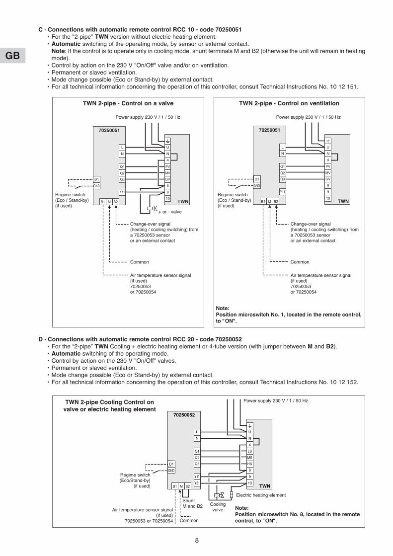
C - Connections with automatic remote control RCC 10 - code 70250051• For the "2-pipe" TWN version without electric heating element.• Automatic switching of the operating mode, by sensor or external contact.
Note: If the control is to operate only in cooling mode, shunt terminals M and B2 (otherwise the unit will remain in heatingmode).
• Control by action on the 230 V "On/Off" valve and/or on ventilation.• Permanent or slaved ventilation.• Mode change possible (Eco or Stand-by) by external contact.• For all technical information concerning the operation of this controller, consult Technical Instructions No. 10 12 151.
D - Connections with automatic remote control RCC 20 - code 70250052• For the “2-pipe” TWN Cooling + electric heating element or 4-tube version (with jumper between M and B2).• Automatic switching of the operating mode.• Control by action on the 230 V "On/Off" valves.• Permanent or slaved ventilation.• Mode change possible (Eco or Stand-by) by external contact.• For all technical information concerning the operation of this controller, consult Technical Instructions No. 10 12 152.
TWN
70250051
N
UL
N
Y11
4
GV
MV
PVQ1
Q2
Q3
8
9
10M B2B1
D1
GND
TWN
70250051
N
UL
N
Y11
4
GV
MV
PVQ1
Q2
Q3
8
9
10M B2B1
D1
GND
TWN 2-pipe - Control on a valve TWN 2-pipe - Control on ventilation
Power supply 230 V / 1 / 50 Hz Power supply 230 V / 1 / 50 Hz
Note:Position microswitch No. 1, located in the remote control,to "ON".
Regime switch(Eco / Stand-by)(if used)
Regime switch(Eco / Stand-by)(if used)
Change-over signal(heating / cooling switching) froma 70250053 sensoror an external contact
Common
Air temperature sensor signal (if used) 70250053or 70250054
Change-over signal(heating / cooling switching) froma 70250053 sensoror an external contact
Common
Air temperature sensor signal (if used) 70250053or 70250054
+ or - valve
TWN
70250052
N
UL
N
Y11
Y21
4
HS
MS
LSQ1
Q2
Q3
8
9
10M B2B1
D1
GND
TWN 2-pipe Cooling Control onvalve or electric heating element
Power supply 230 V / 1 / 50 Hz
Regime switch(Eco/Stand-by)
(if used)
Air temperature sensor signal (if used)
70250053 or 70250054 Common
Coolingvalve
ShuntM and B2
Electric heating element
Note:Position microswitch No. 8, located in the remotecontrol, to "ON".
GB
9
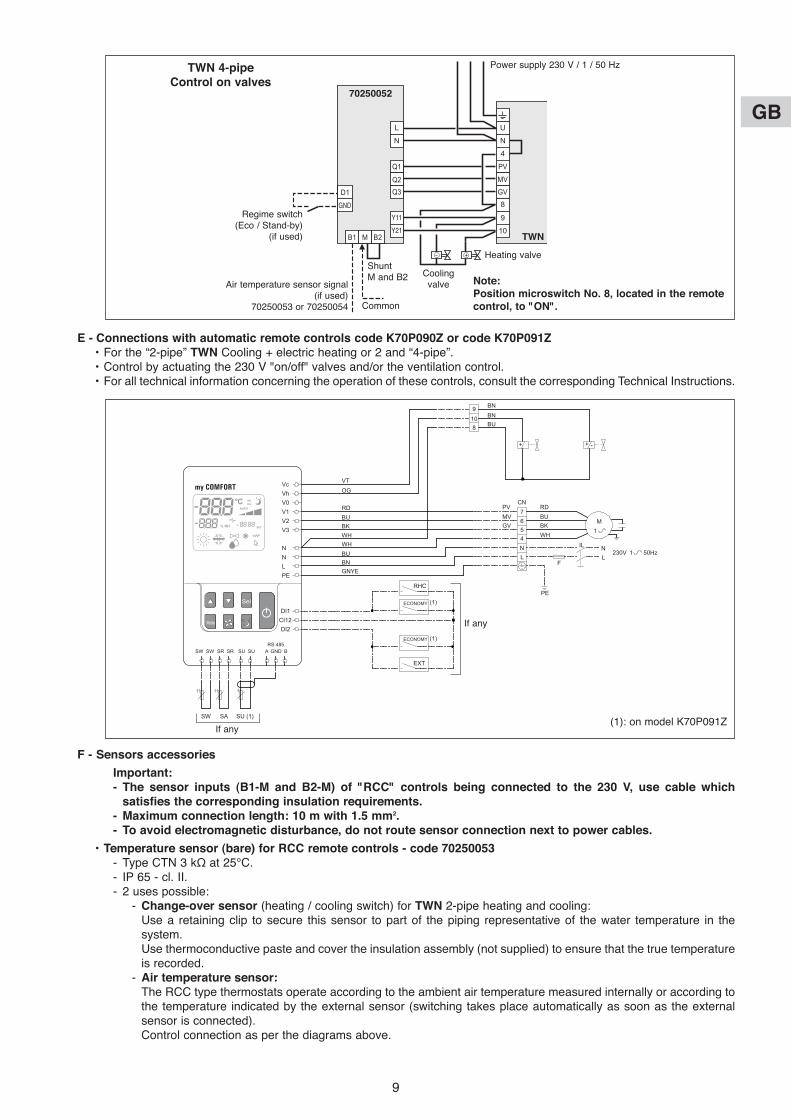
TWN
70250052
N
UL
N
Y11
Y21
4
GV
MV
PVQ1
Q2
Q3
8
9
10M B2B1
D1
GND
+
TWN 4-pipeControl on valves
Power supply 230 V / 1 / 50 Hz
Regime switch(Eco / Stand-by)
(if used)
Air temperature sensor signal (if used)
70250053 or 70250054 Common
Coolingvalve
ShuntM and B2
Heating valve
Note:Position microswitch No. 8, located in the remotecontrol, to "ON".
E - Connections with automatic remote controls code K70P090Z or code K70P091Z• For the “2-pipe” TWN Cooling + electric heating or 2 and “4-pipe”.• Control by actuating the 230 V "on/off" valves and/or the ventilation control.• For all technical information concerning the operation of these controls, consult the corresponding Technical Instructions.
F - Sensors accessories
Important:- The sensor inputs (B1-M and B2-M) of "RCC" controls being connected to the 230 v, use cable which
satisfies the corresponding insulation requirements.- Maximum connection length: 10 m with 1.5 mm2.- To avoid electromagnetic disturbance, do not route sensor connection next to power cables.
• Temperature sensor (bare) for RCC remote controls - code 70250053- Type CTN 3 kΩ at 25°C.- IP 65 - cl. II.- 2 uses possible:
- Change-over sensor (heating / cooling switch) for TWN 2-pipe heating and cooling:Use a retaining clip to secure this sensor to part of the piping representative of the water temperature in thesystem.Use thermoconductive paste and cover the insulation assembly (not supplied) to ensure that the true temperatureis recorded.
- Air temperature sensor:The RCC type thermostats operate according to the ambient air temperature measured internally or according tothe temperature indicated by the external sensor (switching takes place automatically as soon as the externalsensor is connected).Control connection as per the diagrams above.
Vc VTOG
RDBUBKWHWHBU
EXT
RHC
ECONOMY
ECONOMY
BNGNYE
BU
RDCN7
9108
654NL
N230V 1
1M
50HzL
F
PE
IL
BUBK
PVMVGV
WH
BNBN
+ +
VhV0V1V2V3
N
DI1
SW SW SR
SW SA
SR SU
SU (1)
(1)
(1)
SU A GNDRS 485
B
CI12DI2
NLPE
-
(1): on model K70P091ZIf any
If any
GB
10
Caution:- If an air recirculation sensor is installed in the unit, the fan must operate on a permanent basis (valve is
mandatory).
• Air temperature sensor in box for RCC remote controls - code 70250054- Type CTN 3 kΩ at 25°C.- IP 30 - cl. II.
- Air temperature sensor:The RCC type thermostats operate according to the ambient air temperature measured internally or according tothe temperature indicated by the external sensor (switching takes place automatically as soon as the externalsensor is connected).Control connection as per the diagrams above.
• Air / water temperature sensor for K70P090Z and K70P091Z - code K70P093Z- Type CTN 10 kΩ at 25°C. - Range -25°C to 100°C.
• Humidity sensor for K70P091Z control only - code K70P094Z- Resistance type.- Range 20 to 90 % RH.
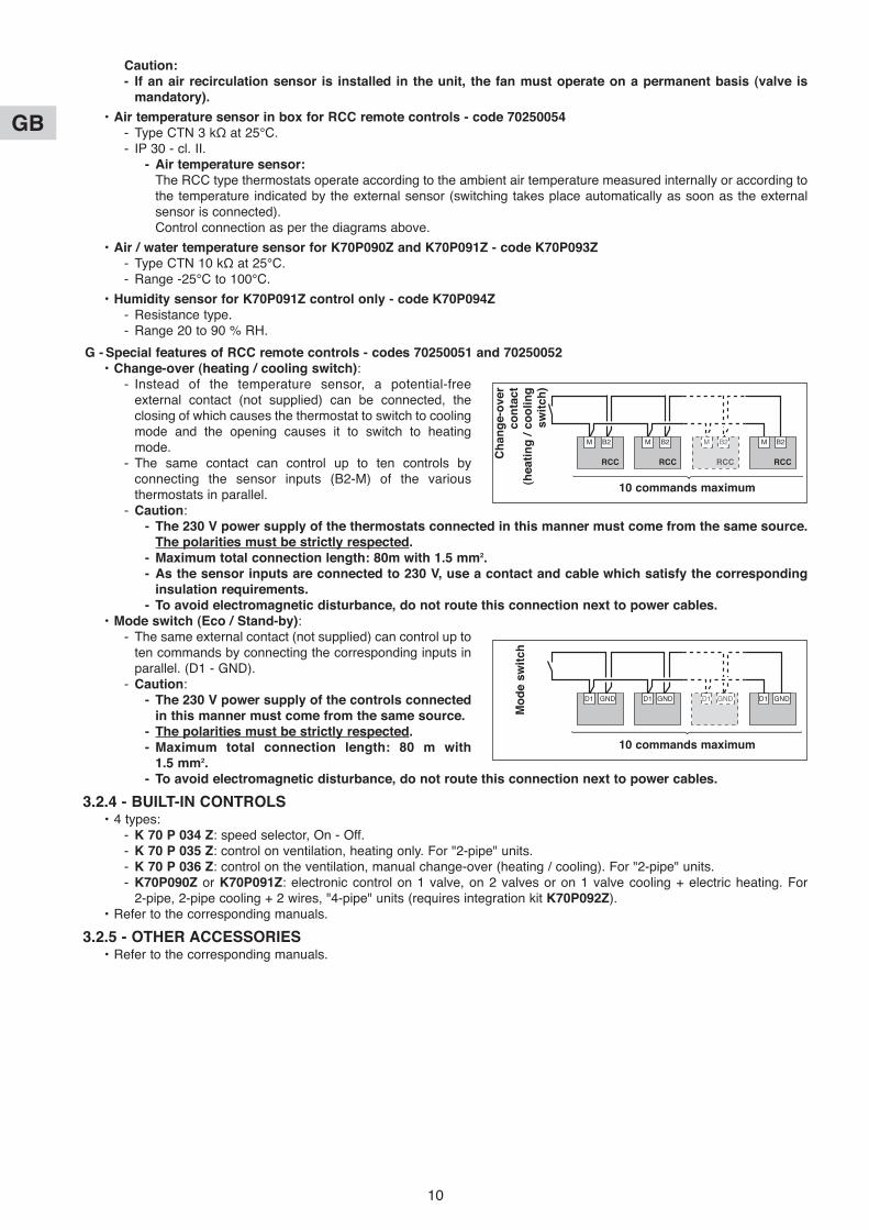
G - Special features of RCC remote controls - codes 70250051 and 70250052• Change-over (heating / cooling switch):
- Instead of the temperature sensor, a potential-freeexternal contact (not supplied) can be connected, theclosing of which causes the thermostat to switch to coolingmode and the opening causes it to switch to heatingmode.
- The same contact can control up to ten controls byconnecting the sensor inputs (B2-M) of the variousthermostats in parallel.
- Caution:- The 230 v power supply of the thermostats connected in this manner must come from the same source.
The polarities must be strictly respected.- Maximum total connection length: 80m with 1.5 mm2.- As the sensor inputs are connected to 230 v, use a contact and cable which satisfy the corresponding
insulation requirements.- To avoid electromagnetic disturbance, do not route this connection next to power cables.
• Mode switch (Eco / Stand-by):- The same external contact (not supplied) can control up to
ten commands by connecting the corresponding inputs inparallel. (D1 - GND).
- Caution:- The 230 v power supply of the controls connected
in this manner must come from the same source.- The polarities must be strictly respected.- Maximum total connection length: 80 m with
1.5 mm2.- To avoid electromagnetic disturbance, do not route this connection next to power cables.
3.2.4 - BUILT-IN CONTROLS• 4 types:
- K 70 P 034 Z: speed selector, On - Off.- K 70 P 035 Z: control on ventilation, heating only. For "2-pipe" units.- K 70 P 036 Z: control on the ventilation, manual change-over (heating / cooling). For "2-pipe" units.- K70P090Z or K70P091Z: electronic control on 1 valve, on 2 valves or on 1 valve cooling + electric heating. For
2-pipe, 2-pipe cooling + 2 wires, "4-pipe" units (requires integration kit K70P092Z). • Refer to the corresponding manuals.
3.2.5 - OTHER ACCESSORIES• Refer to the corresponding manuals.
RCC
M B2
RCC
M B2
RCC
M B2
RCC
M B2
10 commands maximumC
han
ge-o
ver
co
nta
ct
(heati
ng
/ c
oo
lin
gsw
itch
)
D1 GND D1 GND D1 GNDD1 GND
10 commands maximum
Mo
de s
wit
ch
GB
11
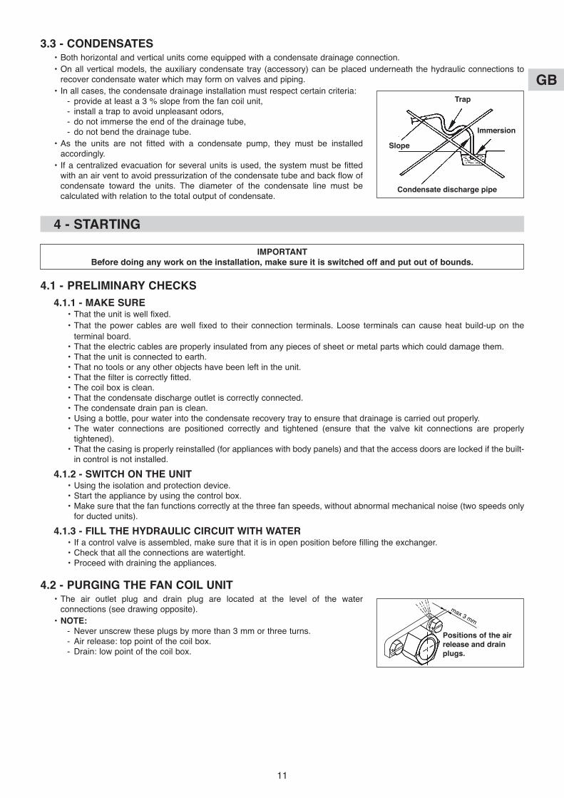
3.3 - CONDENSATES• Both horizontal and vertical units come equipped with a condensate drainage connection.
• On all vertical models, the auxiliary condensate tray (accessory) can be placed underneath the hydraulic connections torecover condensate water which may form on valves and piping.
• In all cases, the condensate drainage installation must respect certain criteria:- provide at least a 3 % slope from the fan coil unit,- install a trap to avoid unpleasant odors,- do not immerse the end of the drainage tube,- do not bend the drainage tube.
• As the units are not fitted with a condensate pump, they must be installedaccordingly.
• If a centralized evacuation for several units is used, the system must be fittedwith an air vent to avoid pressurization of the condensate tube and back flow ofcondensate toward the units. The diameter of the condensate line must becalculated with relation to the total output of condensate.
Trap
Slope
Condensate discharge pipe
Immersion
4 - STARTING
4.1 - PRELIMINARY CHECKS
4.1.1 - MAKE SURE• That the unit is well fixed.
• That the power cables are well fixed to their connection terminals. Loose terminals can cause heat build-up on the
terminal board.• That the electric cables are properly insulated from any pieces of sheet or metal parts which could damage them.• That the unit is connected to earth.• That no tools or any other objects have been left in the unit.• That the filter is correctly fitted.• The coil box is clean.• That the condensate discharge outlet is correctly connected.• The condensate drain pan is clean.• Using a bottle, pour water into the condensate recovery tray to ensure that drainage is carried out properly.• The water connections are positioned correctly and tightened (ensure that the valve kit connections are properly
tightened).• That the casing is properly reinstalled (for appliances with body panels) and that the access doors are locked if the built-
in control is not installed.
4.1.2 - SWITCH ON THE UNIT• Using the isolation and protection device.• Start the appliance by using the control box.• Make sure that the fan functions correctly at the three fan speeds, without abnormal mechanical noise (two speeds only
for ducted units).
4.1.3 - FILL THE HYDRAULIC CIRCUIT WITH WATER• If a control valve is assembled, make sure that it is in open position before filling the exchanger.• Check that all the connections are watertight.• Proceed with draining the appliances.
4.2 - PURGING THE FAN COIL UNIT• The air outlet plug and drain plug are located at the level of the water
connections (see drawing opposite).
• NOTE:- Never unscrew these plugs by more than 3 mm or three turns.- Air release: top point of the coil box.- Drain: low point of the coil box.
IMPORTANTBefore doing any work on the installation, make sure it is switched off and put out of bounds.
max 3 mm
Positions of the airrelease and drainplugs.

GB
12
6 - INTERNAL WIRING DIAGRAM
SYMBOLS OF COMPONENTS
C CapacitorM Motor
COLOURS OF THE WIRES
B BlueN BlackR RedW White
U
N
PV
MV
GV
8
9
10
N
B
R
W
C
M
4
5 - MAINTENANCE INSTRUCTIONS
GENERAL MAINTENANCEAll equipment must be properly maintained in order to provide optimum performance over time. Faulty maintenance can result inthe cancellation of the product guaranty. Depending on the products, maintenance operations consist in the cleaning of filters (air,water), internal and external exchangers, casings, and the cleaning and protection of condensate tanks. Treating odours and thedisinfection of room surfaces and volumes also contributes to the cleanliness of the air breathed by users.
• Cleaning:
- Never use solvents or powerful chemical products.
- Do not use excessively hot water to clean the unit (risk of burns).
• Check the condition of the appliance regularly and clean the coil as well as thecondensate drain pan.
Both sides of the coil must be cleaned, by using a vacuum cleaner with a rubber endpiece and by taking care not to damage the surfaces of the coil.
Periods between maintenance operations depend on local conditions and must bedefined according to case.
• Check that the condensate tank and line are clean and that the line is unobstructed.
• Check the cleanliness of the electric box and that the wires are well connected intheir terminals.
• The motor bearings are self-lubricating and therefore must not be greased.
• The filters are reusable and must be cleaned regularly with warm water (once amonth). Corrosive cleaning agents are not to be used to clean filters.
It is recommended that the filter be replaced with a new filter once a year.
A clogged filter decreases the appliance’s efficiency increases motor noiseand the windings could even break due to overheating.
• To extract the filter, proceed as shown in the drawing opposite.
NC
Cv
CH
GB
13
F
GB
D
I
E

F
GB
D
I
E
REMARQUE : Ce symbole et ce système de recyclage s'appliquent uniquement aux pays del’UE. Ils ne s'appliquent pas aux pays des autres régions du monde.
NOTE: This symbol mark and recycle system are applied only to EU countries and not appliedto the countries in the other area of the world.
NOTA : Questo simbolo e il sistema di riciclaggio sono validi soltanto per i paesi dell’UnioneEuropea e non sono validi per i paesi nel resto del mondo.
NOTA : Este símbolo y el sistema de reciclaje solamente son para países de la UE y no son aplicables a países de otras áreas del mundo.
HINWEIS : Dieses Symbol und Recycle-System gelten nur für Länder der Europäischen Union,nicht für andere Länder der Welt.
F
GB
I
E
D
Votre produit est conçu et fabriqué avec des matériels et des composants de qualité supérieure qui peuvent être recyclés etréutilisés.En fin de vie, il doit être éliminé séparément des ordures ménagères.Nous vous prions donc de confier cet équipement à votre centre local de collecte/recyclage.Dans l’Union Européenne, il existe des systèmes sélectifs de collecte pour les produits électriques et électroniques usagés.Aidez-nous à conserver l’environnement dans lequel nous vivons !Les appareils contiennent fréquemment des matières qui, si elles sont traitées ou éliminées de manière inapropriées, peuvents’avérer potentiellement dangereuses pour la santé humaine et pour l’environnement.Cependant, ces matières sont nécessaires au bon fonctionnement de votre appareil ou de votre machine. Pour cette raison, ilvous est demandé de ne pas vous débarrasser de votre appareil ou machine usagé avec vos ordures ménagères.
Your product is designed and manufactured with high quality materials and components which can be recycled and reused.At end of livetime, it should be eliminated separately from your household waste.Please dispose of this equipment at your local community waste collection/recycling centre.In the European Union there are separate collection systems for used electrical and electronic products.Please help us to conserve the environment we live in!Some equipments contain substances that are considered dangerous to the environment and human health if they are disposed of carelessly.These substances, however, are required for your apparatus or machine to work properly. For this reason, it is requested thatit not be disposed of with other household waste at the end of its service life.
Il vostro prodotto è stato costruito da materiali e componenti di alta qualità, che sono riutilizzabili o riciclabili.Alla fine della sua vita utile deve essere smaltito separatamente dai rifiuti domestici.Vi preghiamo di smaltire questo apparecchio in un centro di raccolta differenziata locale.Nell'Unione Europea esistono sistemi di raccolta differenziata per prodotti elettrici ed elettronici.Aiutateci a conservare l'ambiente in cui viviamo!Gli apparecchi contengono spesso dei materiali che, se trattati od eliminati in modo non adeguato, possono dimostrarsi potenzialmente pericolosi per la salute umana e per l'ambiente.Tuttavia, questi materiali sono necessari per il corretto funzionamento del vostro apparecchio o della vostra macchina. Per que-sto motivo, si richiede di non eliminare il proprio apparecchio o macchina usata assieme ai rifiuti domestici comuni.
Los productos están diseñados y fabricados con materiales y componentes de alta calidad, que pueden ser reciclados y reutilizados.Al final de su ciclo de vida, no se debe desechar con el resto de residuos domésticos. Por favor, deposite su viejo “aparato” enel punto de recogida de residuos o contacte con su administración local.En la Unión Europea existen sistemas de recogida específicos para residuos de aparatos eléctricos y electrónicos.Por favor, ayúdenos a conservar el medio ambiente!Los aparatos a menudo contienen materiales que, si son tratados o eliminados de forma inadecuada, pueden convertirse enpotencialmente peligrosos para la salud humana y para el medio ambiente.No obstante, estos materiales son necesarios para el buen funcionamiento de su máquina. Por esta razón, le rogamos encarecidamente que al final de la vida útil de su aparato, no lo tire junto con la basura doméstica, sino que lo recicle adecuadamente.
Ihr Produkt wurde entworfen und hergestellt mit qualitativ hochwertigen Materialien und Komponenten, die recycelt und wiederverwendet werden können.Am Ende ihrer Nutzungsdauer muss er getrennt vom Hausmüll eliminier werden sollen.Bitte entsorgen Sie dieses Gerät bei Ihrer örtlichen kommunalen Sammelstelle oder im Recycling Centre.In der Europäischen Union gibt es unterschiedliche Sammelsysteme für Elektrik- und Elektronikgeräte.Helfen Sie uns bitte, die Umwelt zu erhalten, in der wir leben!Die Geräte enthalten häufig Bestandteile aus bestimmten Werkstoffen, die bei einer nicht ordnungsgemäßen Behandlung oderEntsorgung eine Belastung für die menschliche Gesundheit und Umwelt darstellen.Diese Werkstoffe sind jedoch für die korrekte Funktionsweise Ihres Gerätes oder Maschine notwendig. Daher bitten wir Sie,Ihr(e) ausgediente(s) Gerät/Maschine nicht in den Hausmüll zu geben.
F
GB
I
E
D
F
GB
D
I
E
Par souci d'amélioration constante, nos produits peuvent être modifiés sans préavis.Due to our policy of continuous development, our products are liable to modification without notice.
Per garantire un costante miglioramento dei nostri prodotti, ci riserviamo di modificarli senza preaviso.En el interés de mejoras constantes, nuestros productos pueden modificarse sin aviso prévio.
Unsere Produkte werden laufend verbessert und können ohne Vorankündigung abgeändert werden.
R.D. 28 Reyrieux BP 131 01601 Trévoux CEDEX FranceTél. 04 74 00 92 92 - Fax 04 74 00 42 00Tel. 33 4 74 00 92 92 - Fax 33 4 74 00 42 00R.C.S. Bourg-en-Bresse B 759 200 728