two-mode hybrid mode - chevrolet · introduction your hybrid pickup is designed to be more fuel...
TRANSCRIPT

2010 Chevrolet Silverado and GMC Sierra Two-mode Hybrid M
In Brief . . . . . . . . . . . . . . . . . . . . . . . . . . . . . . . . . . . . . . . . . . . . 1-1Initial Drive Information . . . . . . . . . . . . . . . . . . . . . . . . . . . 1-2Hybrid Features . . . . . . . . . . . . . . . . . . . . . . . . . . . . . . . . . . 1-2
Seats and Restraint System . . . . . . . . . . . . . . . . . . . . . . 2-1Rear Seats . . . . . . . . . . . . . . . . . . . . . . . . . . . . . . . . . . . . . . . 2-2Restraint System Check . . . . . . . . . . . . . . . . . . . . . . . . . . 2-2
Features and Controls . . . . . . . . . . . . . . . . . . . . . . . . . . . . 3-1Storage Areas . . . . . . . . . . . . . . . . . . . . . . . . . . . . . . . . . . . . 3-2Starting and Operating Your Vehicle . . . . . . . . . . . . . 3-14
Instrument Panel . . . . . . . . . . . . . . . . . . . . . . . . . . . . . . . . . 4-1Climate Controls . . . . . . . . . . . . . . . . . . . . . . . . . . . . . . . . . . 4-2Warning Lights, Gages, and Indicators . . . . . . . . . . . 4-3Driver Information Center (DIC) . . . . . . . . . . . . . . . . . 4-11Audio System(s) . . . . . . . . . . . . . . . . . . . . . . . . . . . . . . . . 4-13
Driving Your Vehicle . . . . . . . . . . . . . . . . . . . . . . . . . . . . . . 5-1Your Driving, the Road, and the Vehicle . . . . . . . . . . 5-2Towing . . . . . . . . . . . . . . . . . . . . . . . . . . . . . . . . . . . . . . . . . . . 5-2
Service and Appearance Care . . . . . . . . . . . . . . . . . . . 6-1Service . . . . . . . . . . . . . . . . . . . . . . . . . . . . . . . . . . . . . . . . . . . 6-2Checking Things Under the Hood . . . . . . . . . . . . . . . . 6-3Electrical System . . . . . . . . . . . . . . . . . . . . . . . . . . . . . . . . 6-23Appearance Care . . . . . . . . . . . . . . . . . . . . . . . . . . . . . . . 6-25Capacities and Specifications . . . . . . . . . . . . . . . . . . . 6-26
Maintenance Schedule . . . . . . . . . . . . . . . . . . . . . . . . . . . 7-1Maintenance Schedule . . . . . . . . . . . . . . . . . . . . . . . . . . . 7-2
Index . . . . . . . . . . . . . . . . . . . . . . . . . . . . . . . . . . . . i-1
GENERAL MOTORS, GM and the GM Emblem,CHEVROLET, the CHEVROLET Emblem, GMC, theGMC Emblem, and the names SILVERADO andSIERRA are registered trademarks of General Motors.
This manual describes features that may or may notbe on your specific vehicle either because they areoptions that you did not purchase or due to changessubsequent to the printing of this owner manual. Pleaserefer to the purchase documentation relating to yourspecific vehicle to confirm each of the features foundon your vehicle. For vehicles first sold in Canada,substitute the name “General Motors of CanadaLimited” for Pontiac Motor Division wherever itappears in this manual.
Keep this manual in the vehicle for quick reference.
Canadian Owners
Propriétaires CanadiensA French language copy of this manual can be obtainedfrom your dealer/retailer or from:
On peut obtenir un exemplaire de ce guide en françaisauprès du concessionnaire ou à l'adresse suivante:
Helm, IncorporatedP.O. Box 07130Detroit, MI 48207
1-800-551-4123
Numéro de poste 6438 de langue française
www.helminc.com
ii
Litho in U.S.A.Part No. 25855011 A First Printing ©2009 General Motors. All Rights Reserved.
IntroductionYour hybrid pickup is designed to be more fuel efficientthan the standard pickup, which results in reducedcarbon dioxide emissions.
Using this SupplementThis supplement contains information specific to thehybrid components of the vehicle. It does not explaineverything you need to know about the vehicle. Readthis supplement along with the owner manual to learnabout the vehicle's features and controls.
IndexA good place to look for what you need is the Index inback of this supplement. It is an alphabetical list of whatis in the supplement, and the page number where youwill find it.
iii

2 NOTES
iv

Section 1 In Brief
Initial Drive Information . . . . . . . . . . . . . . . . . . . . . . . . . . . 1-2Transmission . . . . . . . . . . . . . . . . . . . . . . . . . . . . . . . . . . . . 1-2
Hybrid Features . . . . . . . . . . . . . . . . . . . . . . . . . . . . . . . . . . . . 1-2Hybrid Safety Information . . . . . . . . . . . . . . . . . . . . . . 1-2Fuel Economy Gage . . . . . . . . . . . . . . . . . . . . . . . . . . . . 1-3Automatic Engine Start/Stop Feature . . . . . . . . . . . . 1-3
Regenerative Braking . . . . . . . . . . . . . . . . . . . . . . . . . . . 1-4Battery . . . . . . . . . . . . . . . . . . . . . . . . . . . . . . . . . . . . . . . . . . 1-4Service . . . . . . . . . . . . . . . . . . . . . . . . . . . . . . . . . . . . . . . . . 1-4
1-1

Initial Drive Information
Transmission
Range Selection Mode
The Range Selection Mode switch is located on theshift lever. To enable the Range Selection feature, movethe column shift lever to the M (Manual) position. Thecurrent range will appear next to the M. This is thehighest attainable range with all lower gears accessible.As an example, when 3 (Third) gear is selected, 1 (First)through 3 (Third) gears are available.
Press the plus/minus buttons, located on thesteering column shift lever, to select the desired rangeof gears for current driving conditions. See AutomaticTransmission Operation in the owner manual.
Cruise control can be used while the vehicle is in RangeSelection Mode.
Hybrid Features
Hybrid Safety InformationThis vehicle has a standard 12-volt battery and ahigh-voltage hybrid battery. Only a trained servicetechnician with the proper knowledge and tools shouldinspect, test, or replace the hybrid battery. See yourdealer/retailer if the hybrid battery needs service.
The 12-volt battery cables, in the engine compartment,are clearly labeled. In emergency situations, firstresponders can cut those cables to disable thehigh-voltage hybrid battery system.
1-2

Fuel Economy Gage
United States Canada
This gage indicates fuel efficiency. To obtain the bestfuel efficiency, operate the vehicle so that the indicatoris in the high efficiency band.
Modifying both braking and acceleration behavior tokeep the indicator in the center of the gage will resultin the best system efficiency and fuel economy.
See Fuel Economy Gage on page 4‑5.
Automatic Engine Start/Stop FeatureStart the engine as you would any other engine. See“Starting the Engine” in the owner manual for moreinformation on starting. The hybrid system providesvery quiet engine starting. If pulling a trailer with trailerbrakes, see Towing a Trailer on page 5‑2 for moreinformation.
Auto StopThe vehicle has an Auto Stop feature. After asuccessful engine start, the engine may turn offand operate in the Auto Stop mode.
Keep your foot firmly on the brake pedal until you areready for the vehicle to move.
Engine OFF and AUTO STOP modes are indicated onthe tachometer display. When the tachometer needleindicates OFF, the engine is not running and will remainoff until the ignition key is placed in the START positionor a remote vehicle start is performed. When thetachometer needle indicates AUTO STOP, the hybridsystem is on, the engine is not running, but may AutoStart at any time without notice. See Tachometer onpage 4‑4 for more information.
A chime will sound if the driver door is opened while inAuto Stop as a reminder that the ignition switch is not inthe LOCK/OFF position. Always turn the ignition switchto LOCK/OFF and remove the key from the ignitionswitch when exiting the vehicle.
1-3

Auto StartThe vehicle also has an Auto Start feature. The enginewill remain off while in Auto Stop mode until vehicleconditions require the engine to run. The near-instantstarting of the engine from Auto Stop mode is calledAuto Start.
EV ModeThe vehicle also has an EV mode which uses onlythe electric motor to move the vehicle. With lightacceleration, the vehicle will drive in EV mode. EVmode is unavailable when the vehicle is out of fuel.
See Starting the Vehicle in the Two‐Mode Hybridsupplement to the owner manual.
Regenerative BrakingRegenerative braking enables the electric drive motor tooperate as a generator when coasting or braking.Energy from the moving vehicle recharges the hybridbattery.
The hydraulic disc brakes work with the regenerativebraking to insure effective braking.
The braking system is computer controlled and blendsthe regenerative braking with the conventional hydraulicdisc brakes to meet any requirements for deceleration.Because the controller applies the hydraulic brakesthrough its high pressure accumulator, you may
occasionally hear the motor driven pump when itrecharges the system. This is normal. In the event of acontroller problem, the brake pedal may be harder topush and the stopping distance may be longer.
See Regenerative Braking, Warning Lights, Gages, andIndicators and Driver Information Center (DIC) in theowner manual.
BatteryThis vehicle has a standard 12-volt battery and ahigh-voltage hybrid battery. When a new standard12-volt battery is needed, see your dealer/retailer forone that has the replacement number shown on theoriginal battery's label.
Only a trained service technician with the properknowledge and tools should inspect, test, or replace thehybrid battery. See your dealer/retailer if the hybridbattery needs service. See Battery on page 6‑17.
ServiceNever try to do your own service on hybrid components.You can be injured and the vehicle can be damaged ifyou try to do your own service work. Service and repairof these hybrid components should only be performedby a trained service technician with the properknowledge and tools. See Doing Your Own ServiceWork on page 6‑2.
1-4

Section 2 Seats and Restraint System
Rear Seats . . . . . . . . . . . . . . . . . . . . . . . . . . . . . . . . . . . . . . . . . 2-2Rear Seat Operation (Hybrid Full Bench) . . . . . . . 2-2
Restraint System Check . . . . . . . . . . . . . . . . . . . . . . . . . . . 2-2Replacing Restraint System Parts Aftera Crash . . . . . . . . . . . . . . . . . . . . . . . . . . . . . . . . . . . . . . . 2-2
2-1

Rear Seats
Rear Seat Operation (Hybrid FullBench)
Folding Rear SeatNotice: Folding a rear seat with the safety beltsstill fastened may cause damage to the seat or thesafety belts. Always unbuckle the safety belts andreturn them to their normal stowed position beforefolding a rear seat.
Make sure that nothing is on the seat.
To fold the seat, slowly pull the seat cushion up.
To return the seat to the normal seating position, slowlypull the seat cushion down.
{ WARNING:
A safety belt that is improperly routed, notproperly attached, or twisted will not provide theprotection needed in a crash. The person wearingthe belt could be seriously injured. After raisingthe rear seatback, always check to be sure thatthe safety belts are properly routed and attached,and are not twisted.
Restraint System Check
Replacing Restraint System PartsAfter a CrashIf an airbag inflates or the vehicle has been in a crash,the vehicle's sensing system may command theautomatic hybrid battery disconnect to open. Thebattery will disconnect. The hybrid battery will be off andthe vehicle will not start. The airbag readiness light and/or SERVICE HYBRID SYSTEM warning message maycome on in the driver information center. See “AirbagReadiness Light” in the owner manual and DriverInformation Center (DIC) on page 4‑11 for moreinformation.
To operate the vehicle, the automatic hybrid batterydisconnect must be serviced by a qualified servicetechnician and sensing system parts will need to bereplaced. Have the vehicle serviced right away.
2-2

Section 3 Features and Controls
Storage Areas . . . . . . . . . . . . . . . . . . . . . . . . . . . . . . . . . . . . . . 3-2Tonneau Cover (Hard Tonneau) . . . . . . . . . . . . . . . . . 3-2Tonneau Cover (Soft Tonneau) . . . . . . . . . . . . . . . . . . 3-7
Starting and Operating Your Vehicle . . . . . . . . . . . . 3-14Starting the Vehicle . . . . . . . . . . . . . . . . . . . . . . . . . . . . 3-14Automatic Transmission Operation . . . . . . . . . . . . . 3-16Engine Coolant Heater . . . . . . . . . . . . . . . . . . . . . . . . . 3-19Regenerative Braking . . . . . . . . . . . . . . . . . . . . . . . . . . 3-21Running the Vehicle While Parked . . . . . . . . . . . . . 3-21
3-1

Storage Areas
Tonneau Cover (Hard Tonneau)
Installing the Cover
{ CAUTION:
An improperly stored cargo cover could be thrownabout the vehicle during a collision or suddenmaneuver. Someone could be injured. If the coveris removed, always store it in the proper storagelocation. After positioning the cargo cover back onthe vehicle, always be sure that it is securelyreattached by properly securing the straps andlatches.
1. Position the tonneau cover onto the top of thepickup box with the locator tabs positioned intothe front stake pockets.
2. Align the front edge of the cover with the frontedge of the bed rail so that it is centered on eachside of the truck bed.
3. Lower the front clamp from its storage position.
3-2
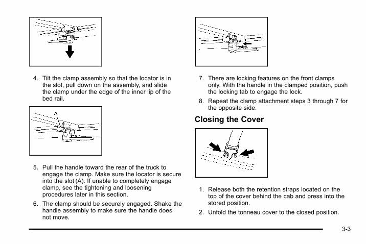
4. Tilt the clamp assembly so that the locator is inthe slot, pull down on the assembly, and slidethe clamp under the edge of the inner lip of thebed rail.
5. Pull the handle toward the rear of the truck toengage the clamp. Make sure the locator is secureinto the slot (A). If unable to completely engageclamp, see the tightening and looseningprocedures later in this section.
6. The clamp should be securely engaged. Shake thehandle assembly to make sure the handle doesnot move.
7. There are locking features on the front clampsonly. With the handle in the clamped position, pushthe locking tab to engage the lock.
8. Repeat the clamp attachment steps 3 through 7 forthe opposite side.
Closing the Cover
1. Release both the retention straps located on thetop of the cover behind the cab and press into thestored position.
2. Unfold the tonneau cover to the closed position.
3-3

3. Lower the rear set of clamp assemblies from thestored position.
4. Tilt the clamp assembly so that the locator is inthe slot, pull down on the assembly, and slidethe clamp under the edge of the inner lip on thebed rail.
5. Pull the handle toward the rear of the truck toengage the clamp. Make sure the locator issecured into the slot (A). If unable to completelyengage clamp, see the tightening and looseningprocedures later in this section.
6. The clamp should be securely engaged. Shake thehandle assembly to make sure the handle doesnot move.
7. Repeat the clamp attachment steps 3 through 6 forthe opposite side.
8. Close the endgate.
Opening the Tonneau Cover1. Turn both of the rear handles inward to release
compression.
2. Pull the clamp down and turn the assemblies todisengage them from the lip of the pickup box.
3. Open the cover to expose the handles.
4. Align the clamp assembly bolt (A) with theretention feature (B).
5. Turn the handle assembly and clamp assemblybolt sideways (A) into the slot of the retentionfeature (B).
3-4

6. The handle should lie flat on the panel with thehandles facing inward. Press firmly to secure.
This step must be done before stowing the cover.
7. Fold the cover forward.
8. Remove the retaining strap from the bow. Connectthe retention buckle ends. One end is located onthe front of the tonneau cover behind the cab andthe other end is on the tonneau cover
9. Pull on each strap to make sure both buckles areattached.
Removing the Tonneau Cover1. Open the cover by following the procedure
described previously, under “Opening theTonneau Cover”.
2. Disengage the locking tabs, located on the fronthandles, by pulling them rearward.
3. Turn the handles inward to release.
4. Pull the clamp down and turn the assembly todisengage it from the lip of the truck box.
5. Turn the cover to expose the handles.
3-5

6. Align the clamp assembly bolt (A), with theretention feature (B).
7. Turn the handle assembly sideways by tilting theassembly bolt (A) into the slot of the retentionfeature (B).
8. The handle should lie flat on the panel with thehandles facing inward. Press firmly to secure.
9. Remove the tonneau cover from the vehicle.
Tightening the Clamp1. Push the handle forward to release it from the
clamped position.
2. Disengage the clamp from the inner edge of thebed rail and slide the assembly inward.
3. Adjust the clamp height on the bolt by turning theentire clamp assembly counter-clockwise.
4. Attach the clamps as indicated in steps 4 and 5 ofInstalling the Cover.
Loosening the Clamp1. Return the handle to the fully disengaged position.
2. Disengage the clamp from the inner edge of thebed rail and slide the assembly inward.
3. Adjust the clamp height by turning the entire clampassembly clockwise.
4. Reattach the clamps as indicated in steps 4 and 5of Installing the Cover.
3-6

Tonneau Cover (Soft Tonneau)
Side Rail
{ WARNING:
An improperly stored cargo cover could be thrownabout the vehicle during a collision or suddenmaneuver. Someone could be injured. If the coveris removed, always store it in the proper storagelocation. After positioning the cargo cover back onthe vehicle, always be sure that it is securelyreattached by properly securing the straps andlatches.
Installation
1. The adjuster screw endof each side rail shouldpoint in the direction ofthe cab.
2. Place each side rail on top of the truck box.
3. Align the front edge of the side rail with the frontinside edge of pickup box.
3-7
Clamp
Installation
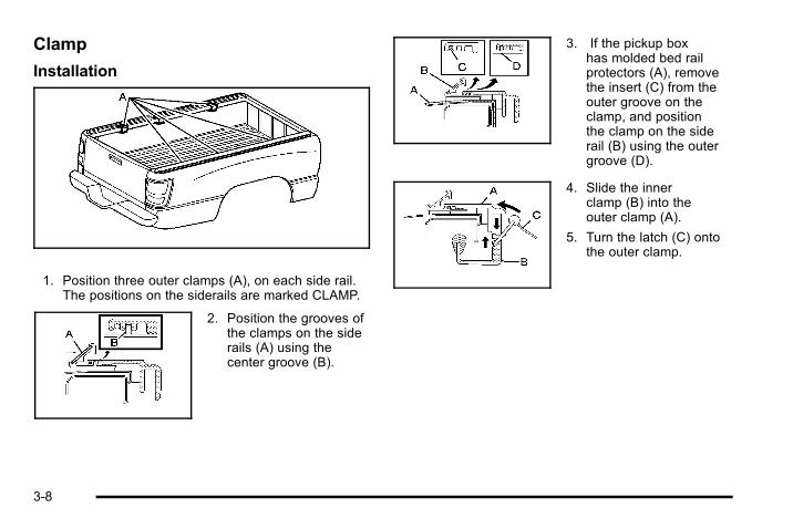
1. Position three outer clamps (A), on each side rail.The positions on the siderails are marked CLAMP.
2. Position the grooves ofthe clamps on the siderails (A) using thecenter groove (B).
3. If the pickup boxhas molded bed railprotectors (A), removethe insert (C) from theouter groove on theclamp, and positionthe clamp on the siderail (B) using the outergroove (D).
4. Slide the innerclamp (B) into theouter clamp (A).
5. Turn the latch (C) ontothe outer clamp.
3-8
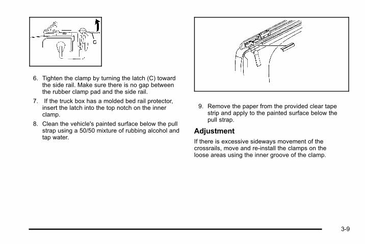
6. Tighten the clamp by turning the latch (C) towardthe side rail. Make sure there is no gap betweenthe rubber clamp pad and the side rail.
7. If the truck box has a molded bed rail protector,insert the latch into the top notch on the innerclamp.
8. Clean the vehicle's painted surface below the pullstrap using a 50/50 mixture of rubbing alcohol andtap water.
9. Remove the paper from the provided clear tapestrip and apply to the painted surface below thepull strap.
AdjustmentIf there is excessive sideways movement of thecrossrails, move and re-install the clamps on theloose areas using the inner groove of the clamp.
3-9

Cover
Installation
1. Place the cover assembly into the front pivotmounts firmly against the adjustment screws.
2. Verify the gap between the adjuster screws andpivot mounts is 3/16 in. Adjust if needed.
3-10
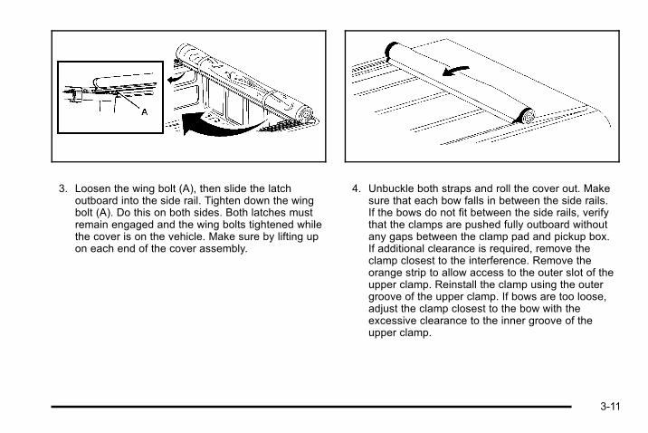
3. Loosen the wing bolt (A), then slide the latchoutboard into the side rail. Tighten down the wingbolt (A). Do this on both sides. Both latches mustremain engaged and the wing bolts tightened whilethe cover is on the vehicle. Make sure by lifting upon each end of the cover assembly.
4. Unbuckle both straps and roll the cover out. Makesure that each bow falls in between the side rails.If the bows do not fit between the side rails, verifythat the clamps are pushed fully outboard withoutany gaps between the clamp pad and pickup box.If additional clearance is required, remove theclamp closest to the interference. Remove theorange strip to allow access to the outer slot of theupper clamp. Reinstall the clamp using the outergroove of the upper clamp. If bows are too loose,adjust the clamp closest to the bow with theexcessive clearance to the inner groove of theupper clamp.
3-11
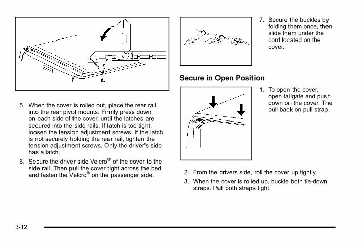
5. When the cover is rolled out, place the rear railinto the rear pivot mounts. Firmly press downon each side of the cover, until the latches aresecured into the side rails. If latch is too tight,loosen the tension adjustment screws. If the latchis not securely holding the rear rail, tighten thetension adjustment screws. Only the driver's sidehas a latch.
6. Secure the driver side Velcro® of the cover to theside rail. Then pull the cover tight across the bedand fasten the Velcro® on the passenger side.
7. Secure the buckles byfolding them once, thenslide them under thecord located on thecover.
Secure in Open Position
1. To open the cover,open tailgate and pushdown on the cover. Thepull back on pull strap.
2. From the drivers side, roll the cover up tightly.
3. When the cover is rolled up, buckle both tie-downstraps. Pull both straps tight.
3-12

Removal
1. Secure the cover (A)into the open position.
2. Loosen wing bolts (B)on both driver andpassenger side of frontrail, then slide latchesinboard until releasedfrom the side rail.
3. Pick the coverassembly up onthe driver side andpull the wholeassembly off thetruck box.
Adjustment
1. If the cover is tooloose, turn thetensioning screwclockwise to tighten thetension of the vinyl.This makes it harder tooperate the rearrelease latch. Thetensioning screws arelocated on each siderail. Use the provided1/4 inch key to turn thetensioning screws.
2. Adjust the screws on both sides to the sametension.
3-13

Starting and Operating YourVehicle
Starting the Vehicle
{ WARNING:
Exiting the vehicle, without first shifting intoP (Park), may cause the vehicle to move, andyou or others can be seriously injured. Becausethe vehicle has the Automatic Engine Start/Stopfeature, the vehicle’s engine might seem to beshut off when you come to a complete stop.However, once the brake pedal is released, thevehicle can move. The vehicle’s engine can alsorestart at any time.
Shift to P (Park) and turn the ignition to LOCK/OFF, before exiting the vehicle.
Start the engine as you would any other engine. See“Starting the Engine” in the owner manual for moreinformation on starting. If pulling a trailer with trailerbrakes, see Towing a Trailer on page 5‑2 for moreinformation.
Auto StopThe vehicle has an Auto Stop feature. After asuccessful engine start, the engine may turn off andoperate in the Auto Stop mode. Some of the vehicleconditions that allow the engine to stop running andenter the Auto Stop mode are:. Ignition switch is in the ON/RUN position.. The hood is closed.. The gear selector is in P (Park), R (Reverse),
N (Neutral) or D (Drive).. The hybrid battery is at an acceptable state of
charge.. The hybrid battery voltage, temperature or power
limits are not exceeded. In very hot conditions,Auto Stop may be unavailable until the hybridbattery has cooled.
. The engine is at operating temperature.
. The vehicle may enter Auto Stop after a remotevehicle start.
If you are on an incline, the hybrid drive motor can helpkeep the vehicle from rolling backwards, even if theengine is in Auto Stop.
With your foot off the brake and the vehicle on levelground, the hybrid drive motor may cause the vehicle toroll slowly forward, even when the engine is inAuto Stop.
3-14
Keep your foot firmly on the brake pedal until you areready for the vehicle to move.
Engine OFF and AUTO STOP modes are indicated onthe tachometer display. When the tachometer needleindicates OFF, the engine is not running and will remainoff until the ignition key is placed in the START positionor a remote vehicle start is performed. When thetachometer needle indicates AUTO STOP, the hybridsystem is on, the engine is not running, but may AutoStart at any time without notice. See Tachometer onpage 4‑4 for more information.
A chime will sound if the driver door is opened while inAuto Stop as a reminder that the ignition switch is not inthe LOCK/OFF position. Always turn the ignition switchto LOCK/OFF and remove the key from the ignitionswitch when exiting the vehicle.
Auto StartThe vehicle also has an Auto Start feature. The enginewill remain off while in Auto Stop mode until vehicleconditions require the engine to run. The near-instantstarting of the engine from Auto Stop mode is calledAuto Start. Some of the vehicle conditions that maycause the engine to Auto Start are:. The hood is opened.. The gear selector is in M (Manual Mode).. The hybrid battery state of charge is too low.
. The hybrid battery voltage, temperature or powerlimits are exceeded.
. A remote vehicle start has been requested.
. The engine is not at operating temperature.
. Acceleration demands require the use of theengine.
EV ModeThe vehicle also has an Electric Vehicle (EV) modewhich uses only the electric motor to move the vehicle.With light acceleration, the vehicle will drive in EVmode. EV mode is unavailable when the vehicle isout of fuel.
If increased acceleration is required, or the vehiclereaches approximately 40 km/h (30 mph), the enginewill start automatically. The engine shuts off at speedsbelow 40 km/h (25 mph) unless the transmission is inM (Manual Mode) or Auto Stop is disabled.
During heavy acceleration, both the engine andhybrid electric motors supply power. A sensationsimilar to a transmission gear change can be feltas the transmission changes modes. Engine RPMmay remain above 4,000 RPM for a longer periodduring hard acceleration.
3-15

Automatic Transmission OperationThe vehicle has an electronic shift position indicatorwithin the instrument panel cluster.
There are several different positions for the shift lever.
See “Range Selection Mode” later in this section.
P (Park) : This position locks the rear wheels. It is thebest position to use when you start the engine becausethe vehicle cannot move easily.
When parked on a hill, especially when the vehicle hasa heavy load, you may notice an increase in the effort toshift out of P (Park). See “Shifting Into P (Park)” in theIndex of vehicle's owner manual for more information.
{ WARNING:
It is dangerous to get out of the vehicle if the shiftlever is not fully in P (Park) with the parking brakefirmly set. The vehicle can roll.
Do not leave the vehicle when the engine isrunning unless you have to. If you have left theengine running, the vehicle can move suddenly.You or others could be injured. To be sure thevehicle will not move, even when you are on fairlylevel ground, always set the parking brake andmove the shift lever to P (Park). See Shifting IntoPark in the Owner Manual. If you are pulling atrailer, see Towing a Trailer on page 5‑2.
3-16

{ WARNING:
If you have Four-Wheel Drive, the vehicle willbe free to roll— even if the shift lever is inP (Park)— if the transfer case is in Neutral. So,be sure the transfer case is in a drive gear,Two-Wheel Drive High or Four-Wheel Drive Highor Four-Wheel Drive Low— not in Neutral. See“Shifting Into Park” in the Owner Manual.
R (Reverse) : Use this gear to back up.
Notice: Shifting to R (Reverse) while the vehicle ismoving forward could damage the transmission.The repairs would not be covered by the vehiclewarranty. Shift to R (Reverse) only after the vehicleis stopped.
To rock the vehicle back and forth to get out of snow,ice, or sand without damaging the transmission, see “IfYour Vehicle is Stuck in Sand, Mud, Ice, or Snow” in theIndex of the vehicle's owner manual.
N (Neutral) : In this position, the engine andtransmission are not connected with the wheels.To restart the engine when the vehicle is alreadymoving, use N (Neutral) only.
{ WARNING:
Shifting into a drive gear while the engine isrunning at high speed is dangerous. Unless yourfoot is firmly on the brake pedal, the vehicle couldmove very rapidly. You could lose control and hitpeople or objects. Do not shift into a drive gearwhile the engine is running at high speed.
Notice: Shifting out of P (Park) or N (Neutral) withthe engine running at high speed may damage thetransmission. The repairs would not be covered bythe vehicle warranty. Be sure the engine is notrunning at high speed when shifting the vehicle.
D (Drive) : This position is for normal driving. It providesthe best fuel economy. If you need more power forpassing, and you are:. Going less than about 35 mph (55 km/h), push the
accelerator pedal about halfway down.. Going about 35 mph (55 km/h) or more, push the
accelerator all the way down.
D (Drive) or M (Manual Mode) can be used whentowing a trailer, carrying a heavy load, driving onsteep hills, or for off-road driving. You may want toshift the transmission to a lower gear selection if thetransmission shifts too often.
3-17

Downshifting the transmission in slippery roadconditions could result in skidding. See “Skidding”under “Loss of Control” in the owner manual formore information.
When temperatures are very cold, the transmission'sgear shifting may be delayed, providing more stableshifts until the engine warms up. Shifts may be morenoticeable with a cold transmission. This difference inshifting is normal.
M (Manual Mode) : This position lets drivers selectthe range of gears appropriate for current drivingconditions. If the vehicle has this feature, see “RangeSelection Mode” later in this section.
Notice: Spinning the tires or holding the vehicle inone place on a hill using only the accelerator pedalmay damage the transmission. The repair will not becovered by the vehicle warranty. If you are stuck, donot spin the tires. When stopping on a hill, use thebrakes to hold the vehicle in place.
The vehicle has a shift stabilization feature thatadjusts the transmission shifting to the current drivingconditions to reduce rapid upshifts and downshifts.If the shift stabilization feature determines that a currentvehicle speed cannot be maintained, the transmissiondoes not upshift. In some cases, this may appear to bea delayed shift, however the transmission is operatingnormally.
Range Selection Mode
The Range Selection Mode controls the vehicle'stransmission.
To use this feature:
1. Move the shift lever to the M (Manual Mode).
2. Press the plus/minus button to upshift or downshiftselecting the desired range of gears.
A number displays next to the M, indicating the currentgear that has been selected. The number displayed inthe gear indicator is the highest gear that can be used.
3-18

The vehicle can automatically shift to lower gears asit adjusts to driving conditions. When 3 (Third) isselected, 1 (First) through 3 (Third) gears areautomatically shifted by the vehicle, but 4 (Fourth)cannot be used until it is selected.
The Range Selection Mode controls the vehicle andengine speed while driving down a hill or towing atrailer, by allowing you to select a desired rangeof gears.
When you move the shift lever into M, the transmissionwill default to M4. In this gear range, effective enginebraking occurs at speeds above 45 mph (72 km/h).
Pushing the minus (−) button on the shift lever reducesthe gear range.
In the M3 gear range, effective engine braking occurs atspeeds above 35 mph (56 km/h).
In the M2 gear range, effective engine braking occurs atspeeds above 25 mph (40 km/h).
In the M1 gear range, effective engine braking occurs atspeeds above 10 mph (16 km/h).
When operating in M (Manual Mode), Auto Stop isdisabled. For better vehicle efficiency, operate thevehicle in D (Drive) not M (Manual Mode).
Cruise control can be used while using the RangeSelection Mode.
Engine Coolant HeaterThe engine coolant heater can provide easier startingand better fuel economy during engine warm-up in coldweather conditions at or below −18°C (0°F). Vehicleswith an engine heater should be plugged in at leastfour hours before starting. An internal thermostat inthe plug-end of the cord may exist which will preventengine coolant heater operation at temperaturesabove −18°C (0°F).
3-19
To Use the Engine Coolant Heater1. Turn off the engine.
2. Open the hood and unwrap the electrical cord. Thecord is secured to a wiring harness between theengine and the Hybrid Auxiliary Underhood FuseBlock with a clip. Carefully remove the wire tiewhich secures the electrical cord. Do not cut theelectrical cord.
3. Plug the cord into a normal, grounded 110-volt ACoutlet.
{ WARNING:
Plugging the cord into an ungrounded outlet couldcause an electrical shock. Also, the wrong kind ofextension cord could overheat and cause a fire.You could be seriously injured. Plug the cord intoa properly grounded three-prong 110-volt ACoutlet. If the cord will not reach, use a heavy-dutythree-prong extension cord rated for at least15 amps.
4. Before starting the engine, be sure to unplug andstore the cord as it was before to keep it away frommoving engine parts. If you do not, it could bedamaged.
The length of time the heater should remain plugged independs on several factors. Ask a dealer/retailer in thearea where you will be parking the vehicle for the bestadvice on this.
3-20

Regenerative BrakingRegenerative braking is a hybrid technology thatenables the electric drive motor to operate as agenerator when coasting or braking. Energy from themoving vehicle recharges the hybrid battery.
The hydraulic disc brakes work with the regenerativebraking to insure effective braking, such as when a highbraking demand is requested.
The braking system is computer controlled and blendsthe regenerative braking with the conventional hydraulicdisc brakes to meet any requirements for deceleration.The controller interprets the braking request and usesregenerative braking, conventional hydraulic braking ora combination of both as necessary. Because thecontroller applies the hydraulic brakes through its highpressure accumulator, you may occasionally hear themotor driven pump when it recharges the system. Thisis normal.
In the event of a controller problem, the brake pedalmay be harder to push and the stopping distance maybe longer.
Running the Vehicle While ParkedIt is better not to park with the engine running. But if youever have to, here are some things to know.
{ WARNING:
Exiting the vehicle, without first shifting intoP (Park), may cause the vehicle to move, and youor others can be seriously injured. Because thevehicle has the Automatic Engine Start/Stopfeature, the vehicle’s engine might seem to beshut off when you come to a complete stop.However, once the brake pedal is released, thevehicle can move. The vehicle’s engine can alsorestart at any time.
Shift to P (Park) and turn the ignition to LOCK/OFF, before exiting the vehicle.
Follow the proper steps to be sure the vehicle will notmove. See “Shifting Into Park” in the owner manual formore information.
If pulling a trailer, see Towing a Trailer on page 5‑2 formore information.
3-21

2 NOTES
3-22
Section 4 Instrument Panel
Climate Controls . . . . . . . . . . . . . . . . . . . . . . . . . . . . . . . . . . . 4-2
Warning Lights, Gages, and Indicators . . . . . . . . . . . 4-3Instrument Panel Cluster . . . . . . . . . . . . . . . . . . . . . . . . 4-3Tachometer . . . . . . . . . . . . . . . . . . . . . . . . . . . . . . . . . . . . . 4-4Charging System Light . . . . . . . . . . . . . . . . . . . . . . . . . . 4-4Fuel Economy Gage . . . . . . . . . . . . . . . . . . . . . . . . . . . . 4-5Brake System Warning Light . . . . . . . . . . . . . . . . . . . . 4-5Antilock Brake System (ABS) Warning Light . . . . 4-7StabiliTrak® Indicator Light . . . . . . . . . . . . . . . . . . . . . . 4-7
Engine Coolant Temperature Gage . . . . . . . . . . . . . 4-8Oil Pressure Gage . . . . . . . . . . . . . . . . . . . . . . . . . . . . . . 4-8Oil Pressure Light . . . . . . . . . . . . . . . . . . . . . . . . . . . . . . . 4-9Fuel Gage . . . . . . . . . . . . . . . . . . . . . . . . . . . . . . . . . . . . . 4-10
Driver Information Center (DIC) . . . . . . . . . . . . . . . . . . 4-11DIC Warnings and Messages . . . . . . . . . . . . . . . . . . 4-11
Audio System(s) . . . . . . . . . . . . . . . . . . . . . . . . . . . . . . . . . . 4-13Navigation/Radio System . . . . . . . . . . . . . . . . . . . . . . 4-13
4-1

Climate ControlsFor more information on the vehicle's climate controlsystem, see “Climate Control System” in the ownermanual.
Electric Air Conditioning CompressorThis hybrid vehicle has a electrically powered airconditioning compressor. This allows for continuous airconditioning operation and passenger comfort, evenwhile the hybrid engine cycles on and off.
When operating the climate control system, select theAUTO mode and the desired temperature setting. Theclimate control system automatically adjusts the fanspeed and airflow direction. The climate control systemcontinues to adjust the climate control settings chosenfor best use of electrical power.
At mild temperatures, select a warmer air conditionertemperature or turn the air conditioner off to getmaximum fuel economy. Continuous air conditioner usecan cause the vehicle to Auto Start more frequently.During hot weather, driving with the windows closed andthe air conditioner set to Auto mode, will result in betterHybrid system performance.
Some noise may be heard occasionally from thecompressor, especially when air conditioning use ishigh and the engine has turned off.
4-2

Warning Lights, Gages, and Indicators
Instrument Panel Cluster
United States version shown, Canada similar
4-3
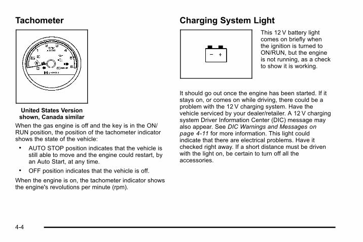
Tachometer
United States Versionshown, Canada similar
When the gas engine is off and the key is in the ON/RUN position, the position of the tachometer indicatorshows the state of the vehicle:. AUTO STOP position indicates that the vehicle is
still able to move and the engine could restart, byan Auto Start, at any time.
. OFF position indicates that the vehicle is off.
When the engine is on, the tachometer indicator showsthe engine's revolutions per minute (rpm).
Charging System LightThis 12 V battery lightcomes on briefly whenthe ignition is turned toON/RUN, but the engineis not running, as a checkto show it is working.
It should go out once the engine has been started. If itstays on, or comes on while driving, there could be aproblem with the 12 V charging system. Have thevehicle serviced by your dealer/retailer. A 12 V chargingsystem Driver Information Center (DIC) message mayalso appear. See DIC Warnings and Messages onpage 4‑11 for more information. This light couldindicate that there are electrical problems. Have itchecked right away. If a short distance must be drivenwith the light on, be certain to turn off all theaccessories.
4-4

Fuel Economy Gage
United States Canada
This gage shows displays how efficiently the vehicle isbeing driven.
There are three zones on the drive efficiency gage.
Green Zone : Fuel efficient driving behavior makes theindicator display in the green zone on the gage.
White Zones : Decreased fuel efficiency drivingbehavior makes the indicator display in the two whitezones. The indicator in the white zone on the left side ofthe gage indicates decreased fuel efficiency with a largeamount of decelerations. The indicator in the white zoneon the right side of the gage indicates decreased fuelefficiency with a large amount of accelerations.
Brake System Warning LightWith the ignition in ON/RUN, the brake system warninglight comes on when the parking brake is set. If thevehicle is driven with the parking brake engaged, achime sounds when the vehicle speed is greater than5 mph (8 km/h).
The vehicle's hydraulic brake system is divided intotwo parts. If one part is not working, the other part canstill work and stop the vehicle. For good braking,though, both parts need to be working well.
If the warning light comes on and a chime sounds therecould be a brake problem. Have the brake systeminspected right away.
4-5

This light also comes on due to low brake fluid. See theowner manual for more information.
United States Canada
This light should come on briefly when the ignition keyis turned to ON/RUN. If it does not come on then, haveit fixed so it will be ready to warn if there is a problem.
{ WARNING:
The brake system might not be working properly ifthe brake system warning light is on. Driving withthe brake system warning light on can lead to acrash. If the light is still on after the vehicle hasbeen pulled off the road and carefully stopped,have the vehicle towed for service.
If the light comes on while driving, pull off the road andstop carefully. The pedal might be harder to push or cango closer to the floor. It may take longer to stop. If thelight does not go out, have the vehicle towed forservice. See Towing Your Vehicle on page 5‑2.
4-6
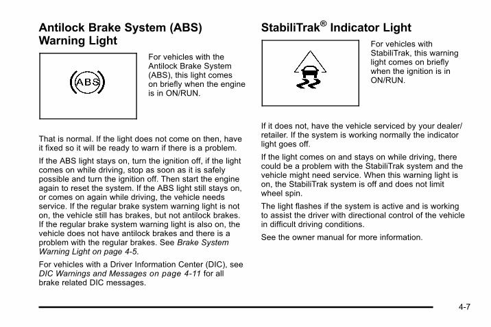
Antilock Brake System (ABS)Warning Light
For vehicles with theAntilock Brake System(ABS), this light comeson briefly when the engineis in ON/RUN.
That is normal. If the light does not come on then, haveit fixed so it will be ready to warn if there is a problem.
If the ABS light stays on, turn the ignition off, if the lightcomes on while driving, stop as soon as it is safelypossible and turn the ignition off. Then start the engineagain to reset the system. If the ABS light still stays on,or comes on again while driving, the vehicle needsservice. If the regular brake system warning light is noton, the vehicle still has brakes, but not antilock brakes.If the regular brake system warning light is also on, thevehicle does not have antilock brakes and there is aproblem with the regular brakes. See Brake SystemWarning Light on page 4‑5.
For vehicles with a Driver Information Center (DIC), seeDIC Warnings and Messages on page 4‑11 for allbrake related DIC messages.
StabiliTrak® Indicator LightFor vehicles withStabiliTrak, this warninglight comes on brieflywhen the ignition is inON/RUN.
If it does not, have the vehicle serviced by your dealer/retailer. If the system is working normally the indicatorlight goes off.
If the light comes on and stays on while driving, therecould be a problem with the StabiliTrak system and thevehicle might need service. When this warning light ison, the StabiliTrak system is off and does not limitwheel spin.
The light flashes if the system is active and is workingto assist the driver with directional control of the vehiclein difficult driving conditions.
See the owner manual for more information.
4-7

Engine Coolant Temperature Gage
United States Canada
This gage shows the engine coolant temperature.
It also provides an indicator of how hard the vehicle isworking. During a majority of the operation, the gagereads 210°F (100°C) or less. If a load is being pulledor going up hills, it is normal for the temperature tofluctuate and go over the 235°F (113°C) mark. However,if the gage reaches the 260°F (125°C) mark, it indicatesthat the cooling system is working beyond its capacity.
Oil Pressure Gage
United States Canada
The oil pressure gage shows the engine oil pressurein psi (pounds per square inch) when the engine isrunning. Canadian vehicles indicate pressure inkPa (kilopascals).
Oil pressure should be 29 to 80 psi (200 to 550 kPa).In certain situations, such as long extended idles onhot days, it could read as low as 15 psi (105 kPa) andstill be considered normal.
A reading in the low pressure zone may be causedby a dangerously low oil level or some other problemcausing low oil pressure. Check the oil as soon aspossible.
4-8

{ WARNING:
Do not keep driving if the oil pressure is low. Theengine can become so hot that it catches fire.Someone could be burned. Check the oil as soonas possible and have the vehicle serviced.
Notice: Lack of proper engine oil maintenancecan damage the engine. The repairs would not becovered by the vehicle warranty. Always follow themaintenance schedule in this manual for changingengine oil.
AUTO STOPWhen the engine goes into Automatic Engine Stop, theoil pressure gage drops to zero when the tachometeris at the AUTO STOP position. This is normal and oilpressure returns to the normal operating range oncethe engine starts.
See Starting the Vehicle on page 3‑14 for moreinformation.
AUTO STOP displays in the Driver Information Center(DIC) when the vehicle speed is zero. See DICWarnings and Messages on page 4‑11 for moreinformation.
Oil Pressure Light
{ WARNING:
Do not keep driving if the oil pressure is low. Theengine can become so hot that it catches fire.Someone could be burned. Check the oil as soonas possible and have the vehicle serviced.
Notice: Lack of proper engine oil maintenancecan damage the engine. The repairs would not becovered by the vehicle warranty. Always follow themaintenance schedule in this manual for changingengine oil.
This light comes on brieflyas a check it works, whenthe ignition is in ON/RUN.If it does not, have thevehicle serviced.
4-9
If the light comes on and stays on, it means that oil isnot flowing through the engine properly. The vehiclecould be low on oil and might have some other systemproblem.
During an AUTO STOP there is zero oil pressure, butthis light will not come on.
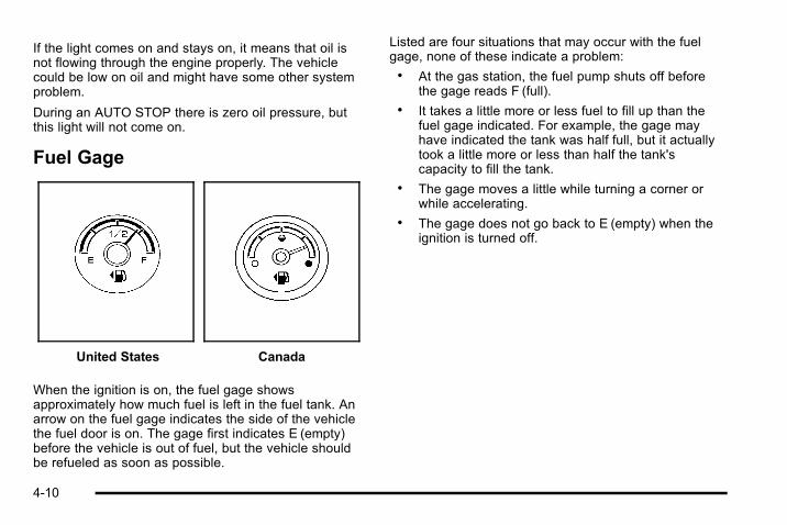
Fuel Gage
United States Canada
When the ignition is on, the fuel gage showsapproximately how much fuel is left in the fuel tank. Anarrow on the fuel gage indicates the side of the vehiclethe fuel door is on. The gage first indicates E (empty)before the vehicle is out of fuel, but the vehicle shouldbe refueled as soon as possible.
Listed are four situations that may occur with the fuelgage, none of these indicate a problem:. At the gas station, the fuel pump shuts off before
the gage reads F (full).. It takes a little more or less fuel to fill up than the
fuel gage indicated. For example, the gage mayhave indicated the tank was half full, but it actuallytook a little more or less than half the tank'scapacity to fill the tank.
. The gage moves a little while turning a corner orwhile accelerating.
. The gage does not go back to E (empty) when theignition is turned off.
4-10

Driver Information Center (DIC)Trip/Fuel Menu ItemsPress the trip/fuel button to display the Trip/Fuel Menuitems. For more items see “DIC Operation andDisplays” in the owner manual.
BATTERY VOLTAGEThis display shows the current battery voltage. If thevoltage is in the normal range, the value will display. Forexample, the display may read BATTERY VOLTAGE13.2 VOLTS. If the voltage is high or low, the display willread HIGH or LOW. Your vehicle's charging systemregulates voltage based on the state of the battery.The battery voltage may fluctuate when viewing thisinformation on the DIC. This is normal. See “ChargingSystem Light” in the owner manual for more information.If there is a problem with the battery charging system,the DIC will display a message. See DIC Warnings andMessages on page 4‑11.
INST ECON (Instantaneous Economy)This display normally shows instantaneous fueleconomy. When the vehicle is in Auto Stop modeAUTO STOP or INST ECON = 99 MPG (l/00km)will be displayed. See Starting the Vehicle onpage 3‑14 for more information.
DIC Warnings and MessagesWarning messages are displayed on the DIC to notifythe driver that the status of the vehicle has changedand that some action may be needed by the driver tocorrect the condition. If there is more than one messagethat needs to be displayed they will appear one afteranother.
Some messages may not require immediate action, butyou can press any of the DIC buttons on the instrumentpanel or the trip odometer reset stem to acknowledgethat you received the messages and to clear them fromthe display.
Some messages cannot be cleared from the DICdisplay because they are more urgent. Thesemessages require action before they can be cleared.You should take any messages that appear on thedisplay seriously and remember that clearing themessages will only make the messages disappear,not correct the problem.
For information on other DIC messages, see “DICWarnings and Messages” in the owner manual Index.
4-11

HOOD OPENIf the hood is not fully closed or there is a problem withthe hood switch, this message will be displayed. Closethe hood to clear the message. If the HOOD OPENmessage continues to be displayed after verifying thehood is closed, you should have the hood switchserviced. Failure to service the hood switch properlycan result in an Auto Start condition.
Auto Stops will be disabled when this message isdisplayed. If the vehicle is in auto stop mode when thismessage appears, the engine will instantly start.
OIL PRESSURE LOW STOP ENGINEIf engine oil pressure is low, this message will bedisplayed on the DIC. Stop the vehicle as soon assafely possible and do not operate it until the cause ofthe low oil pressure has been corrected. Check your oillevel as soon as possible and have your vehicleserviced. See “Engine Oil” in the owner manual Index.
SERVICE BATTERY CHARGINGSYSTEMIf the 12V battery system faults or fails this message willappear on the DIC. The battery/charging system lightwill appear in the instrument panel cluster. See “Battery
Warning Light” in the owner manual Index. Driving withthis message on could drain the battery. Have theelectrical system checked as soon as possible.
SERVICE BRAKE SYSTEMThis message will be displayed if there is a problemwith the brake system. You will still be able to brake, butit will be noticeably more difficult. Pull off the road to asafe location and have your vehicle towed to thenearest dealer/retailer for service. See “Brakes,” “BrakeSystem Warning Light,” and “ABS Brake SystemWarning Light” in the owner manual Index.
SERVICE HYBRID SYSTEMIf this message is displayed on the DIC, the vehicle maycontinue to operate, but you need to have it serviced assoon as possible.
SERVICE POWER STEERINGThis message displays if a problem has been detectedwith the electric power steering. Have your vehicleserviced by your dealer/retailer immediately.
4-12

Audio System(s)
Navigation/Radio SystemFor vehicles with a navigation radio system, see theNavigation System manual for more information.
To view the hybrid screen, press the MENU button onthe radio. The hybrid screen displays when entering theConfiguration Menu.
The display shows:. Auto Stop. Battery Charging. Engine Idle. 2‐Wheel and 4‐Wheel Drive Modes for:
‐ Engine Power
‐ Battery Power
‐ Hybrid Power
4-13

2 NOTES
4-14

Section 5 Driving Your Vehicle
Your Driving, the Road, and the Vehicle . . . . . . . . . . 5-2Electric Power Steering . . . . . . . . . . . . . . . . . . . . . . . . . 5-2
Towing . . . . . . . . . . . . . . . . . . . . . . . . . . . . . . . . . . . . . . . . . . . . . 5-2Towing Your Vehicle . . . . . . . . . . . . . . . . . . . . . . . . . . . . 5-2Towing a Trailer . . . . . . . . . . . . . . . . . . . . . . . . . . . . . . . . . 5-2
5-1

Your Driving, the Road, and theVehicle
Electric Power SteeringThis vehicle has On-Demand Electric-Assist PowerSteering instead of conventional full-time hydraulicpower steering. It uses electricity supplied by the samebattery which is re-charged by the regenerative brakingsystem.
Because the system is On-Demand Electric-Assist,energy is used only when the steering wheel is turned,or when the steering gear is used to help isolate theforces of rough roads. This system does not use powersteering fluid, making it maintenance-free.
Towing
Towing Your VehicleConsult your dealer/retailer or a professional towingservice if the disabled vehicle needs to be towed.
Towing a TrailerFor more information, see “Towing a Trailer” in theowner manual Index.
Weight of the TrailerHow heavy can a trailer safely be?
It depends on how the rig is used. For example,speed, altitude, road grades, outside temperature andhow much the vehicle is used to pull a trailer are allimportant. It can depend on any special equipment onthe vehicle, and the amount of tongue weight thevehicle can carry.
Maximum trailer weight is calculated assuming only thedriver is in the tow vehicle and it has all the requiredtrailering equipment. The weight of additional optionalequipment, passengers and cargo in the tow vehiclemust be subtracted from the maximum trailer weight.
Use the following charts to determine how much thevehicle can weigh, based upon the vehicle model andoptions.
5-2

Vehicle Axle Ratio Maximum Trailer Weight GCWR*
2WD 6.0 L V8 3.08 6,100 lbs (2 767 kg) 12,000 lbs (5 443 kg)
4WD 6.0 L V8 3.08 5,900 lbs (2 676 kg) 12,000 lbs (5 443 kg)
*The Gross Combination Weight Rating (GCWR) is the total allowable weight of the completely loaded vehicle andtrailer including any passengers, cargo, equipment and conversions. The GCWR for the vehicle should not beexceeded.
Trailer BrakesIf a trailer is being towed that has trailer brakes and thetrailer brakes are manually applied while driving slowerthan 25 mph (40 km/h), the vehicle may go into autostop mode even if the brakes are not being pressed.Using the trailer brake system manually can make thehybrid vehicle perform as if the brake pedal in thevehicle is being pressed. The trailer brake operation
check will still work. If the trailer brakes are manuallyapplied for an extended period of time, the SERVICEBRAKE SYSTEM DIC message comes on. Themessage goes off after the trailer brakes have beenreleased. No other action is necessary. For moreinformation, see “Trailer Brakes” in the Index of thevehicle's owner manual.
5-3

2 NOTES
5-4

Section 6 Service and Appearance Care
Service . . . . . . . . . . . . . . . . . . . . . . . . . . . . . . . . . . . . . . . . . . . . . 6-2Doing Your Own Service Work . . . . . . . . . . . . . . . . . . 6-2
Checking Things Under the Hood . . . . . . . . . . . . . . . . . 6-3High Voltage Devices and Wiring . . . . . . . . . . . . . . . 6-3Engine Compartment Overview . . . . . . . . . . . . . . . . . 6-4Automatic Transmission Fluid . . . . . . . . . . . . . . . . . . . 6-5Drive Motor/Generator Control Module (DMCM)Coolant Surge Tank Pressure Cap . . . . . . . . . . . . 6-8
Drive Motor/Generator Control Module (DMCM)Cooling System . . . . . . . . . . . . . . . . . . . . . . . . . . . . . . . 6-9
Power Steering Fluid . . . . . . . . . . . . . . . . . . . . . . . . . . 6-13
Brakes . . . . . . . . . . . . . . . . . . . . . . . . . . . . . . . . . . . . . . . . . 6-13Battery . . . . . . . . . . . . . . . . . . . . . . . . . . . . . . . . . . . . . . . . . 6-17Jump Starting . . . . . . . . . . . . . . . . . . . . . . . . . . . . . . . . . . 6-18
Electrical System . . . . . . . . . . . . . . . . . . . . . . . . . . . . . . . . . 6-23High Voltage Devices and Wiring . . . . . . . . . . . . . . 6-23Fuses and Circuit Breakers . . . . . . . . . . . . . . . . . . . . 6-24Underhood Fuse Block . . . . . . . . . . . . . . . . . . . . . . . . 6-24
Appearance Care . . . . . . . . . . . . . . . . . . . . . . . . . . . . . . . . . 6-25Vehicle Care/Appearance Materials . . . . . . . . . . . . 6-25
Capacities and Specifications . . . . . . . . . . . . . . . . . . . 6-26
6-1

Service
Doing Your Own Service Work
{ WARNING:
Never try to do your own service on hybridcomponents. You can be injured and the vehiclecan be damaged if you try to do your own servicework. Service and repair of these hybridcomponents should only be performed by atrained service technician with the properknowledge and tools.
{ WARNING:
You can be injured and the vehicle could bedamaged if you try to do service work on a vehiclewithout knowing enough about it.
. Be sure you have sufficient knowledge,experience, the proper replacement parts,and tools before attempting any vehiclemaintenance task.
. Be sure to use the proper nuts, bolts, andother fasteners. English and metric fastenerscan be easily confused.If the wrong fasteners are used, parts canlater break or fall off. You could be hurt.
6-2

If doing some of your own service work, use the properservice manual. It tells you much more about how toservice the vehicle than this manual can. To order theproper service manual, see “Service PublicationsOrdering Information” in the owner manual.
This vehicle has an airbag system. Before attemptingto do your own service work, see “Servicing YourAirbag‐Equipped Vehicle” in the owner manual.
Keep a record with all parts receipts and list the mileageand the date of any service work performed. See“Maintenance Record” in the owner manual.
Checking Things Underthe Hood
High Voltage Devices and Wiring
{ WARNING:
Exposure to high voltage can cause shock, burns,and even death. The high voltage systems in yourvehicle can only be serviced by technicians withspecial training.
High voltage devices are identified by labels. Donot remove, open, take apart, or modify thesedevices. High voltage cable or wiring has orangecovering. Do not probe, tamper with, cut,or modify high voltage cable or wiring.
6-3

Engine Compartment OverviewWhen you open the hood on your vehicle, you will see:
6-4
A. See “Engine Air Cleaner/Filter” in the ownermanual.
B. Drive Motor/Generator Control Module (DMCM).See Drive Motor/Generator Control Module(DMCM) Cooling System on page 6‑9.
C. Engine Oil Dipstick. See “Engine Oil” in the ownermanual.
D. Automatic Transmission Fluid Dipstick. SeeAutomatic Transmission Fluid on page 6‑5.
E. Brake Fluid Reservoir. See Brakes on page 6‑13.
F. See “Underhood Fuse Block” in the owner manual.
G. See “Windshield Washer Fluid” in the ownermanual.
H. Hybrid Auxiliary Fuse Block. See Underhood FuseBlock on page 6‑24.
I. DMCM Coolant Surge Tank Pressure Cap. SeeDrive Motor/Generator Control Module (DMCM)Coolant Surge Tank Pressure Cap on page 6‑8.
J. See “Coolant Surge Tank Pressure Cap” in theowner manual.
K. Engine Oil Fill Cap. See “Engine Oil” in the ownermanual.
Automatic Transmission Fluid
When to Check and Change AutomaticTransmission FluidIt is usually not necessary to check the transmissionfluid level. The only reason for fluid loss is atransmission leak or overheating the transmission.If you suspect a small leak, then use the followingchecking procedures to check the fluid level. However,if there is a large leak, then it may be necessary to havethe vehicle towed to a dealer/retailer service departmentand have it repaired before driving the vehicle further.
Notice: Use of the incorrect automatic transmissionfluid may damage the vehicle, and the damages maynot be covered by the vehicle's warranty. Alwaysuse the automatic transmission fluid listed inRecommended Fluids and Lubricants on page 7‑2.
Change the fluid and filter at the intervals listed in theMaintenance Schedule. See Scheduled Maintenance inthe owner manual. Be sure to use the transmission fluidlisted in Recommended Fluids and Lubricants onpage 7‑2 .
6-5

How to Check Automatic TransmissionFluidNotice: Too much or too little fluid can damage yourtransmission. Too much can mean that some of thefluid could come out and fall on hot engine parts orexhaust system parts, starting a fire. Too little fluidcould cause the transmission to overheat. Be sureto get an accurate reading if you check yourtransmission fluid.
Before checking the fluid level, prepare the vehicle asfollows:
1. Start the engine and park the vehicle on a levelsurface. Keep the engine running.
2. Apply the parking brake and place the shift lever inP (Park).
3. With your foot on the brake pedal, move the shiftlever through each gear range, pausing for aboutthree seconds in each range. Then, move the shiftlever back to P (Park).
4. Allow the engine to idle (500 – 800 RPM) for atleast one minute. Slowly release the brake pedal.
5. Keep the engine running and press the Trip/Fuelbutton or trip odometer reset stem until TRANSTEMP (Transmission Temperature) displays on theDriver Information Center (DIC).
6. Using the TRANS TEMP reading, determine andperform the appropriate check procedure. If theTRANS TEMP reading is not within the requiredtemperature ranges, allow the vehicle to cool,or operate the vehicle until the appropriatetransmission fluid temperature is reached.
Cold Check ProcedureUse this procedure only as a reference to determine ifthe transmission has enough fluid to be operated safelyuntil a hot check procedure can be made. The hotcheck procedure is the most accurate method to checkthe fluid level. Perform the hot check procedure at thefirst opportunity. Use this cold check procedure to checkfluid level when the transmission temperature isbetween 24°C and 34°C (75°F and 93°F).
1. Locate thetransmission dipstick atthe rear of the enginecompartment, on thepassenger side of thevehicle.
See Engine Compartment Overview on page 6‑4for more information.
2. Pull out the dipstick and wipe it with a clean rag orpaper towel.
6-6

3. Install the dipstick by pushing it back in all the way,wait three seconds, and then pull it back out again.
4. Check both sides of the dipstick and read the lowerlevel. Repeat the check procedure to verify thereading.
5. If the fluid level is below the COLD check band,add only enough fluid as necessary to bring thelevel into the COLD band. It does not take muchfluid, generally less than 0.5 Liter (1 Pint). Do notoverfill.
6. Perform a hot check at the first opportunity afterthe transmission reaches a normal operatingtemperature between 60°C and 75°C (140°Fand 167°F).
7. If the fluid level is in the acceptable range, pushthe dipstick back in all the way.
Hot Check ProcedureUse this procedure to check the transmission fluid levelwhen the transmission fluid temperature is between60°C and 75°C (140°F and 167°F).
The hot check is the most accurate method to check thefluid level. The hot check should be performed at thefirst opportunity in order to verify the cold check. Thefluid level rises as fluid temperature increases, so it isimportant to ensure the transmission temperature iswithin range.
1. Locate thetransmission dipstick atthe rear of the enginecompartment, on thepassenger side of thevehicle.
See Engine Compartment Overview on page 6‑4for more information.
2. Pull out the dipstick and wipe it with a clean rag orpaper towel.
3. Install the dipstick by pushing it back in all the way,wait three seconds, and then pull it back out again.
4. Check both sides of the dipstick and read the lowerlevel. Repeat the check procedure to verify thereading.
6-7

5. Safe operating level is within the HOT cross hatchband on the dipstick. If the fluid level is not withinthe HOT band, and the transmission temperatureis between 60°C and 75°C (140°F and 167°F), addor drain fluid as necessary to bring the level intothe HOT band. If the fluid level is low, add onlyenough fluid to bring the level into the HOT band.It does not take much fluid, generally less than0.5 Liter (1 Pint). Do not overfill.
6. If the fluid level is in the acceptable range, pushthe dipstick back in all the way.
Consistency of ReadingsAlways check the fluid level at least twice usingthe procedure described previously. Consistency(repeatable readings) is important to maintainingproper fluid level. If readings are still inconsistent,contact your dealer/retailer.
Drive Motor/Generator ControlModule (DMCM) Coolant Surge TankPressure Cap
See Engine CompartmentOverview on page 6‑4for more information onlocation.
6-8

The Drive Motor/Generator Control Module (DMCM)coolant surge tank pressure cap must be fully installedon the hybrid coolant surge tank.
Notice: If the pressure cap is not tightly installed,coolant loss and possible damage to the DriveMotor/Generator Control Module (DMCM) may occur.Be sure the cap is properly and tightly secured.
Drive Motor/Generator ControlModule (DMCM) Cooling SystemIn addition to the regular cooling system, the vehiclealso has a cooling system for the DMCM system. Thissystem is serviced differently than the vehicle's maincooling system. The DMCM cooling system includes theDMCM coolant surge tank, DMCM surge tank pressurecap, DMCM cooling pumps, hybrid cooling radiator andthe Drive Motor/Generator Control Module (DMCM).The DMCM cooling system uses a 50/50 pre-mixedDEX-COOL™ coolant and deionized water available atyour dealer/retailer. See “Engine Coolant” and “CoolingSystem” in the owner manual for more information.
When you decide it is safe to lift the hood, here is whatyou will see:
A. Drive Motor/GeneratorControl Module (DMCM)
B. Engine Coolant SurgeTank Pressure Cap
C. DMCM Coolant SurgeTank/Engine CoolantSurge Tank
D. DMCM CoolingHoses (Out of View)
E. DMCM CoolantTank Pressure Cap
6-9

If the coolant inside the DMCM coolant surge tank isboiling, do not do anything else until it cools down.
The coolant level should be at or above the FULLCOLD mark with the vehicle parked on a level surface.If it is not, there might be a leak at the DMCM coolercore, DMCM pressure cap, DMCM cooler hoses,DMCM cooling pump or somewhere else in the DMCMcooling system.
Notice: Running the engine when there is a leak inthe hybrid cooling system can cause the hybridcooling system to lose all coolant and can damagethe system. Get any leak fixed before you drive thevehicle or run the engine.
How to Add Coolant to the DMCMCoolant Surge Tank
If no problem has been found yet, check to see ifcoolant is visible in the DMCM coolant surge tank.If coolant is visible, add pre‐mixed DEX-COOL™coolant, available at your dealer/retailer, at the DMCMcoolant surge tank, but be sure the DMCM coolingsystem, including the DMCM coolant surge tankpressure cap, is cool before you do it. Use theprocedure following.
6-10

{ WARNING:
Steam and scalding liquids from a hot coolingsystem can blow out and burn you badly. They areunder pressure, and if you turn the coolant surgetank pressure cap— even a little— they can comeout at high speed. Never turn the cap when thecooling system, including the coolant surge tankpressure cap, is hot. Wait for the cooling systemand coolant surge tank pressure cap to cool if youever have to turn the pressure cap.
Notice: Using coolant other than a pre‐mixedDEX-COOL, available at your dealer/retailer, maydamage your vehicle. Any repairs would not becovered by your warranty. Always use a pre‐mixedDEX-COOL (silicate-free) coolant in your vehicle.
{ WARNING:
You can be burned if you spill coolant on hotengine parts. Coolant contains ethylene glycoland it will burn if the engine parts are hot enough.Do not spill coolant on a hot engine.
If the DMCM coolant is empty , the vehicle must beserviced by your dealer and a special fill proceduremust be followed.
Notice: Attempting to fill the DMCM cooling surgetank yourself when the fluid level is empty candamage your vehicle. Your vehicle must beserviced.
1. Park the vehicle on a level surface and turn thevehicle off. Remove the DMCM coolant surge tankpressure cap when the DMCM cooling system,including the DMCM coolant surge tank pressurecap and DMCM cooling hoses, are no longer hot.
6-11
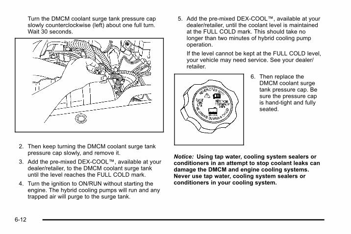
Turn the DMCM coolant surge tank pressure capslowly counterclockwise (left) about one full turn.Wait 30 seconds.
2. Then keep turning the DMCM coolant surge tankpressure cap slowly, and remove it.
3. Add the pre‐mixed DEX‐COOL™, available at yourdealer/retailer, to the DMCM coolant surge tankuntil the level reaches the FULL COLD mark.
4. Turn the ignition to ON/RUN without starting theengine. The hybrid cooling pumps will run and anytrapped air will purge to the surge tank.
5. Add the pre‐mixed DEX‐COOL™, available at yourdealer/retailer, until the coolant level is maintainedat the FULL COLD mark. This should take nolonger than two minutes of hybrid cooling pumpoperation.
If the level cannot be kept at the FULL COLD level,your vehicle may need service. See your dealer/retailer.
6. Then replace theDMCM coolant surgetank pressure cap. Besure the pressure capis hand-tight and fullyseated.
Notice: Using tap water, cooling system sealers orconditioners in an attempt to stop coolant leaks candamage the DMCM and engine cooling systems.Never use tap water, cooling system sealers orconditioners in your cooling system.
6-12
Power Steering FluidThe vehicle has electric power steering and does notuse power steering fluid.
Brakes
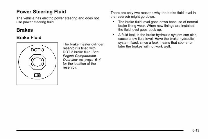
Brake FluidThe brake master cylinderreservoir is filled withDOT 3 brake fluid. SeeEngine CompartmentOverview on page 6‑4for the location of thereservoir.
There are only two reasons why the brake fluid level inthe reservoir might go down:. The brake fluid level goes down because of normal
brake lining wear. When new linings are installed,the fluid level goes back up.
. A fluid leak in the brake hydraulic system can alsocause a low fluid level. Have the brake hydraulicsystem fixed, since a leak means that sooner orlater the brakes will not work well.
6-13
Do not top off the brake fluid. Adding fluid does notcorrect a leak. If fluid is added when the linings areworn, there will be too much fluid when new brakelinings are installed. Add or remove brake fluid, asnecessary, only when work is done on the brakehydraulic system.
{ WARNING:
If too much brake fluid is added, it can spill on theengine and burn, if the engine is hot enough. Youor others could be burned, and the vehicle couldbe damaged. Add brake fluid only when work isdone on the brake hydraulic system. See“Checking Brake Fluid” in this section.
When the brake fluid falls to a low level, the brakewarning light comes on. See “Brake System WarningLight” in the owner manual.
Refer to the Maintenance Schedule to determine whento check the brake fluid. See “Scheduled Maintenance”in the owner manual.
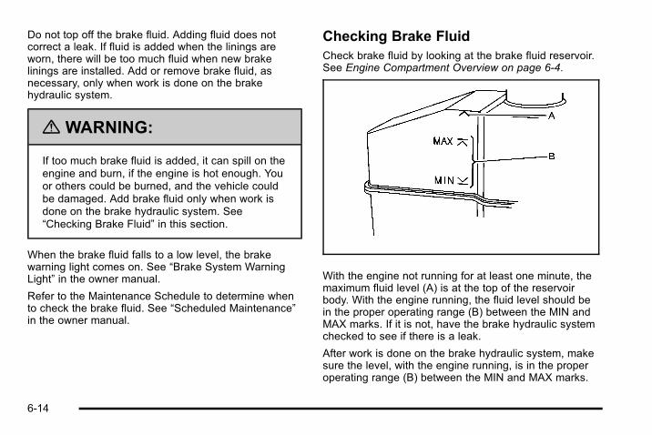
Checking Brake FluidCheck brake fluid by looking at the brake fluid reservoir.See Engine Compartment Overview on page 6‑4.
With the engine not running for at least one minute, themaximum fluid level (A) is at the top of the reservoirbody. With the engine running, the fluid level should bein the proper operating range (B) between the MIN andMAX marks. If it is not, have the brake hydraulic systemchecked to see if there is a leak.
After work is done on the brake hydraulic system, makesure the level, with the engine running, is in the properoperating range (B) between the MIN and MAX marks.
6-14

What to AddUse only new DOT 3 brake fluid from a sealedcontainer. See “Recommended Fluids and Lubricants”in the owner manual.
Always clean the brake fluid reservoir cap and the areaaround the cap before removing it. This helps keep dirtfrom entering the reservoir.
{ WARNING:
With the wrong kind of fluid in the brake hydraulicsystem, the brakes might not work well. This couldcause a crash. Always use the proper brake fluid.
Notice:. Using the wrong fluid can badly damage
brake hydraulic system parts. For example,just a few drops of mineral-based oil, suchas engine oil, in the brake hydraulic systemcan damage brake hydraulic system parts sobadly that they will have to be replaced. Donot let someone put in the wrong kind offluid.
. If brake fluid is spilled on the vehicle'spainted surfaces, the paint finish can bedamaged. Be careful not to spill brakefluid on the vehicle. If you do, wash it offimmediately. See “Washing Your Vehicle”in the owner manual.
6-15

Brake WearThis vehicle has disc brakes. Disc brake pads havebuilt-in wear indicators that make a high-pitchedwarning sound when the brake pads are worn and newpads are needed. The sound can come and go or beheard all the time the vehicle is moving, except whenapplying the brake pedal firmly.
{ WARNING:
The brake wear warning sound means that soonthe brakes will not work well. That could lead toan accident. When the brake wear warning soundis heard, have the vehicle serviced.
Notice: Continuing to drive with worn-out brakepads could result in costly brake repair.
Some driving conditions or climates can cause a brakesqueal when the brakes are first applied or lightlyapplied. This does not mean something is wrong withthe brakes.
Properly torqued wheel nuts are necessary to helpprevent brake pulsation. When tires are rotated, inspectbrake pads for wear and evenly tighten wheel nuts inthe proper sequence to torque specifications in“Capacities and Specifications” in the owner manual.
Brake linings should always be replaced as completeaxle sets.
Brake Pedal TravelSee your dealer/retailer if the brake pedal does notreturn to normal height, or if there is a rapid increase inpedal travel. This could be a sign that brake servicemight be required.
Brake AdjustmentEvery time the brakes are applied, the disc brakesadjust for wear.
6-16
Replacing Brake System PartsThe braking system on a vehicle is complex. Its manyparts have to be of top quality and work well together ifthe vehicle is to have really good braking. The vehiclewas designed and tested with top-quality brake parts.When parts of the braking system are replaced — forexample, when the brake linings wear down and newones are installed — be sure to get new approvedreplacement parts. If this is not done, the brakes mightnot work properly. For example, if someone puts inbrake linings that are wrong for the vehicle, the balancebetween the front and rear brakes can change — for theworse. The braking performance expected can changein many other ways if the wrong replacement brakeparts are installed.
BatteryThis vehicle has a standard 12‐volt battery and ahigh‐voltage hybrid battery.
Refer to the replacement number on the original batterylabel when a new standard 12‐volt battery is needed.
Only a trained service technician with the properknowledge and tools should inspect, test, or replacethe hybrid battery. See your dealer/retailer if the hybridbattery needs service. The dealer/retailer hasinformation on how to recycle the hybrid battery.There is also information available athttp://www.recyclemybattery.com.
If an airbag inflates or the vehicle has been in a crash,the vehicle's sensing system might command theautomatic hybrid battery disconnect to open. SeeReplacing Restraint System Parts After a Crash onpage 2‑2 for more information .
{ DANGER:
Battery posts, terminals, and related accessoriescontain lead and lead compounds, chemicalsknown to the State of California to cause cancerand reproductive harm. Wash hands afterhandling.
6-17
Vehicle Storage
{ WARNING:
Batteries have acid that can burn you and gasthat can explode. You can be badly hurt if you arenot careful. See Jump Starting on page 6‑18 fortips on working around a battery withoutgetting hurt.
Infrequent Usage: Remove the 12‐volt battery black,negative (−) cable from the battery to keep the batteryfrom running down.
Extended Storage: Remove the 12‐volt battery black,negative (−) cable from the battery or use a batterytrickle charger.
Remember to reconnect the battery when ready to drivethe vehicle.
Jump Starting
{ WARNING:
Personal injury, death, or damage to the vehiclecan result if you try jump starting or using abattery charger on the high voltage hybrid battery.Use only the 12-volt battery for jump starting andcharging.
If the vehicle's 12‐volt battery has run down, you maywant to use another vehicle and some jumper cables tostart your vehicle. Use the following steps to do it safely.
{ WARNING:
Batteries can hurt you. They can be dangerousbecause:. They contain acid that can burn you.
. They contain gas that can explode or ignite.
. They contain enough electricity to burn you.
If you do not follow these steps exactly, some orall of these things can hurt you.
6-18
Notice: Ignoring these steps could result in costlydamage to the vehicle that would not be covered bythe warranty.
Trying to start the vehicle by pushing or pulling itwill not work, and it could damage the vehicle.
1. Check the other vehicle. It must have a 12‐voltbattery with a negative ground system.
Notice: If the other vehicle's system is not a 12-voltsystem with a negative ground, both vehicles canbe damaged. Only use vehicles with 12-volt systemswith negative grounds to jump start your vehicle.
2. Get the vehicles close enough so the jumpercables can reach, but be sure the vehicles are nottouching each other. It could cause a groundconnection you do not want. You would not be ableto start your vehicle, and the bad grounding coulddamage the electrical systems.
To avoid the possibility of the vehicles rolling, setthe parking brake firmly on both vehicles involvedin the jump start procedure. Put the automatictransmission in P (Park) or a manual transmission
in N (Neutral) before setting the parking brake.If you have a four-wheel-drive vehicle, be sure thetransfer case is in a drive gear, not in N (Neutral).
Notice: If you leave the radio or other accessorieson during the jump starting procedure, they couldbe damaged. The repairs would not be covered bythe warranty. Always turn off the radio and otheraccessories when jump starting the vehicle.
3. Turn off the ignition on both vehicles. Unplugunnecessary accessories plugged into thecigarette lighter or the accessory power outlets.Turn off the radio and all the lamps that are notneeded.
This avoids sparks and helps save both batteries.It could save the radio!
4. Open the hood on the other vehicle and locate thepositive (+) and negative (−) terminal locations onthat vehicle.
6-19

The positive (+) connection is located under a redplastic cover at the positive battery post. Touncover the remote positive (+) terminal, open thered plastic cover.
5. The remote negative (−) is a solid engine ground.
{ WARNING:
An electric fan can start up even when the engineis not running and can injure you. Keep hands,clothing and tools away from any underhoodelectric fan.
{ WARNING:
Using an open flame near a battery can causebattery gas to explode. People have been hurtdoing this, and some have been blinded. Use aflashlight if you need more light.
Be sure the battery has enough water. You do notneed to add water to the battery installed in yournew vehicle. But if a battery has filler caps, besure the right amount of fluid is there. If it is low,add water to take care of that first. If you do not,explosive gas could be present.
Battery fluid contains acid that can burn you. Donot get it on you. If you accidentally get it in youreyes or on your skin, flush the place with waterand get medical help immediately.
6-20

{ WARNING:
Fans or other moving engine parts can injure youbadly. Keep your hands away from moving partsonce the engine is running.
6. Check that the jumper cables do not have loose ormissing insulation. If they do, you could get ashock. The vehicles could be damaged too.
Before you connect the cables, here are somebasic things you should know. Positive (+) goes topositive (+) or to a remote positive (+) terminal ifthe vehicle has one. Negative (−) will go to aheavy, unpainted metal engine part or a solidengine ground.
Do not connect positive (+) to negative (−) or youwill get a short that would damage the battery andmaybe other parts too. Do not connect thenegative (−) cable to the negative (−) terminal onthe dead battery because this can cause sparks.
7. Connect the red positive (+) cable to thepositive (+) terminal of the vehicle with the deadbattery. Use a remote positive (+) if the vehiclehas one.
8. Do not let the other end touch metal. Connect it tothe positive (+) terminal of the good battery. Use aremote positive (+) if the vehicle has one.
9. Now connect the black negative (−) cable to thenegative (−) terminal of the good battery. Use aremote negative (−) if the vehicle has one.
Do not let the other end touch anything until thenext step. The other end of the negative (−) cabledoes not go to the dead battery. It goes to a heavy,unpainted metal engine part or to the remotenegative (−) terminal on the vehicle with the deadbattery.
6-21

10. Connect the other end of the negative (−) cable tothe remote negative (−) terminal, on the vehiclewith the dead battery.
11. Now start the vehicle with the good battery and runthe engine for a while.
12. Try to start the vehicle that had the dead battery.If it will not start after a few tries, it probably needsservice.
Notice: If the jumper cables are connected orremoved in the wrong order, electrical shorting mayoccur and damage the vehicle. The repairs wouldnot be covered by the vehicle warranty. Alwaysconnect and remove the jumper cables in thecorrect order, making sure that the cables do nottouch each other or other metal.
Jumper Cable Removal
A. Heavy, Unpainted Metal Engine Part or RemoteNegative (−) Terminal
B. Good Battery or Remote Positive (+) and RemoteNegative (−) Terminals
C. Dead Battery or Remote Positive (+) Terminal
6-22

To disconnect the jumper cables from both vehicles:
1. Disconnect the black negative (−) cable from thevehicle that had the bad battery.
2. Disconnect the black negative (−) cable from thevehicle with the good battery.
3. Disconnect the red positive (+) cable from thevehicle with the good battery.
4. Disconnect the red positive (+) cable from the othervehicle.
5. Return the remote positive (+) terminal cover to itsoriginal position.
Electrical System
High Voltage Devices and Wiring
{ WARNING:
Exposure to high voltage can cause shock, burns,and even death. The high voltage systems in yourvehicle can only be serviced by technicians withspecial training.
High voltage devices are identified by labels. Donot remove, open, take apart, or modify thesedevices. High voltage cable or wiring has orangecovering. Do not probe, tamper with, cut,or modify high voltage cable or wiring.
6-23

Fuses and Circuit BreakersThe wiring circuits in the vehicle are protected fromshort circuits by a combination of fuses, circuit breakersand fusible thermal links. This greatly reduces thechance of fires caused by electrical problems.
Be sure you replace a bad fuse with a new one of theidentical size and rating.
If you ever have a problem on the road and do not havea spare fuse, you can borrow one that has thesame amperage. Just pick some feature of the vehiclethat you can get along without, like the radio or cigarettelighter, and use its fuse, if it is the correct amperage.Replace it as soon as you can.
The vehicle also has a special fuse in the battery boxfor the 300-volt batteries. If this fuse has failed andneeds to be replaced, the vehicle will be disabled andyou will need to have the vehicle repaired by yourdealer/retailer. Do not attempt to self-service this fuse.
Underhood Fuse Block
Hybrid Auxiliary Underhood Fuse BlockThe hybrid underhood fuse block is located in theengine compartment near the front of the vehicle. Liftthe cover for access to the fuse/relay block. See EngineCompartment Overview on page 6‑4 for more
information on its location. For more information on themain underhood fuse block, see “Underhood FuseBlock” in the owner manual.
Fuses Usage
1 ACPO (SUV Only)
2 BECM FAN
3 ACCM
4 CAB HTR PMP
5 EMPTY
6 COOL PUMP
7 EPS
6-24

Fuses Usage
8Drive Motor/Generator Control
Module 1
9Drive Motor/Generator Control
Module 2
10 BECM
J‐Case Usage
FAN 1 Cooling Fan 1
TRANS PUMPAuxiliary Transmission
Fluid Pump
FAN 2 Cooling Fan 2
CAB HTR PMP Cab Heater Pump
Relays Usage
FAN LOW Cooling Fan Low Speed Relay
FAN MID 1 Cooling Fan Mid 1
FAN HI Cooling Fan High Speed Relay
FAN MID 2 Cooling Fan Mid 2
FAN CNTRL Cooling Fan Control
Appearance Care
Vehicle Care/Appearance MaterialsWhen scraping the windshield glass to remove ice andsnow, stay clear of the hybrid decal.
To have the hybrid decals removed from the vehicle,please see your dealer/retailer.
6-25

Capacities and Specifications
ApplicationCapacities
English Metric
Automatic Transmission* (Pan Removal and FilterReplacement)
11.5 qt 10.9 L
Cooling System
Drive Motor Generator Control Module Cooling System 2.9 qt 2.7 L
6.0L V8 Engine Cooling System 17.2 qt 16.3 L
Fuel Tank 26.0 gal 98.4 L
*See Automatic Transmission Fluid on page 6 ‑5 for information on checking fluid level.
All capacities are approximate. Recheck fluid level after filling.
Engine SpecificationsEngine VIN Code Transmission Spark Plug Gap
6.0LV8 J Automatic 0.040 in (1.02 mm)
6-26
Section 7 Maintenance Schedule
Maintenance Schedule . . . . . . . . . . . . . . . . . . . . . . . . . . . . 7-2Recommended Fluids and Lubricants . . . . . . . . . . . 7-2Engine Drive Belt Routing . . . . . . . . . . . . . . . . . . . . . . . 7-2
7-1

Maintenance Schedule
Recommended Fluids andLubricantsFluids identified below are specific to the hybrid vehicleand can be obtained from your dealer/retailer. See theowner manual for the other fluids and lubricantsrecommended for the vehicle.
Usage Fluid/Lubricant
Drive Motor/Generator
Control Module(DMCM) Cooling
System
Always use the pre-mixed50/50 mixture of de‐ionized water andDEX-COOL® (silicate-free) coolantavailable at your dealer/retailer. SeeDrive Motor/Generator Control Module(DMCM) Cooling System onpage 6 ‑9 .
Engine Drive Belt Routing
7-2
AAntilock Brake System (ABS)Warning Light . . . . . . . . . . . . . . . . . . . . . . . . . . . . . . . . . . . . . . 4-7
Audio System(s)Navigation/Radio System . . . . . . . . . . . . . . . . . . . . . . . . . 4-13
Automatic Transmission, Fluid . . . . . . . . . . . . . . . . . . . . . . .6-5
BBattery . . . . . . . . . . . . . . . . . . . . . . . . . . . . . . . . . . . . . . . . . . . . 6-17Belt Routing, Engine . . . . . . . . . . . . . . . . . . . . . . . . . . . . . . . . .7-2Brakes . . . . . . . . . . . . . . . . . . . . . . . . . . . . . . . . . . . . . . . . . . . . . 6-13Regenerative Braking . . . . . . . . . . . . . . . . . . . . . . . . . . . . . 3-21System Warning Light . . . . . . . . . . . . . . . . . . . . . . . . . . . . . 4-5
CCanadian Owners . . . . . . . . . . . . . . . . . . . . . . . . . . . . . . . . . . . . . iiCapacities and Specifications . . . . . . . . . . . . . . . . . . . . . . 6-26Charging System Light . . . . . . . . . . . . . . . . . . . . . . . . . . . . . .4-4Climate Controls . . . . . . . . . . . . . . . . . . . . . . . . . . . . . . . . . . . . .4-2CoolantEngine Temperature Gage . . . . . . . . . . . . . . . . . . . . . . . . . 4-8
Coolant Surge Tank Pressure Cap, (DMCM) . . . . . . . . .6-8Cooling System, (DMCM) . . . . . . . . . . . . . . . . . . . . . . . . . . . .6-9CoversTonneau . . . . . . . . . . . . . . . . . . . . . . . . . . . . . . . . . . . . . . 3-2, 3-7
DDrive Motor/Generator Control Module (DMCM)Coolant Surge Tank Pressure Cap . . . . . . . . . . . . . . . . .6-8
Drive Motor/Generator Control Module (DMCM)Cooling System . . . . . . . . . . . . . . . . . . . . . . . . . . . . . . . . . . . .6-9
Driver Information Center (DIC) . . . . . . . . . . . . . . . . . . . . 4-11Warnings and Messages . . . . . . . . . . . . . . . . . . . . . . . . . 4-11
EEngineCompartment Overview . . . . . . . . . . . . . . . . . . . . . . . . . . . . 6-4Coolant Temperature Gage . . . . . . . . . . . . . . . . . . . . . . . . 4-8Drive Belt Routing . . . . . . . . . . . . . . . . . . . . . . . . . . . . . . . . . 7-2
Engine Coolant Heater . . . . . . . . . . . . . . . . . . . . . . . . . . . . 3-19
FFluidPower Steering . . . . . . . . . . . . . . . . . . . . . . . . . . . . . . . . . . . 6-13
FuelGage . . . . . . . . . . . . . . . . . . . . . . . . . . . . . . . . . . . . . . . . . . . . . 4-10
Fuel Economy Gage . . . . . . . . . . . . . . . . . . . . . . . . . . . . . . . . .4-5
i - 1
GGagesEngine Coolant Temperature . . . . . . . . . . . . . . . . . . . . . . 4-8Fuel . . . . . . . . . . . . . . . . . . . . . . . . . . . . . . . . . . . . . . . . . . . . . . 4-10Fuel Economy . . . . . . . . . . . . . . . . . . . . . . . . . . . . . . . . . . . . . 4-5Oil Pressure . . . . . . . . . . . . . . . . . . . . . . . . . . . . . . . . . . . . . . . 4-8Tachometer . . . . . . . . . . . . . . . . . . . . . . . . . . . . . . . . . . . . . . . . 4-4
HHigh Voltage Devices and Wiring . . . . . . . . . . . . . . . . . . . .6-3
IInstrument Panel Cluster . . . . . . . . . . . . . . . . . . . . . . . . . . . .4-3Introduction . . . . . . . . . . . . . . . . . . . . . . . . . . . . . . . . . . . . . . . . . . . iii
JJump Starting . . . . . . . . . . . . . . . . . . . . . . . . . . . . . . . . . . . . . . 6-18
LLightsAntilock Brake System (ABS) Warning . . . . . . . . . . . . . 4-7Brake System Warning . . . . . . . . . . . . . . . . . . . . . . . . . . . . 4-5Charging System . . . . . . . . . . . . . . . . . . . . . . . . . . . . . . . . . . 4-4Oil Pressure . . . . . . . . . . . . . . . . . . . . . . . . . . . . . . . . . . . . . . . 4-9StabiliTrak® Indicator . . . . . . . . . . . . . . . . . . . . . . . . . . . . . . 4-7
MMaintenance ScheduleRecommended Fluids and Lubricants . . . . . . . . . . . . . 7-2
Manual, How to Use . . . . . . . . . . . . . . . . . . . . . . . . . . . . . . . . . . iii
i - 2
NNavigation/Radio System . . . . . . . . . . . . . . . . . . . . . . . . . . 4-13
OOilPressure Light . . . . . . . . . . . . . . . . . . . . . . . . . . . . . . . . . . . . . 4-9
Oil Pressure Gage . . . . . . . . . . . . . . . . . . . . . . . . . . . . . . . . . . .4-8Owners, Canadian . . . . . . . . . . . . . . . . . . . . . . . . . . . . . . . . . . . . . ii
PPowerSteering Fluid . . . . . . . . . . . . . . . . . . . . . . . . . . . . . . . . . . . . . 6-13
RRadiosNavigation/Radio System . . . . . . . . . . . . . . . . . . . . . . . . . 4-13
Rear Seat Operation . . . . . . . . . . . . . . . . . . . . . . . . . . . . . . . . .2-2Recommended Fluids and Lubricants . . . . . . . . . . . . . . .7-2
Regenerative Braking . . . . . . . . . . . . . . . . . . . . . . . . . . . . . . 3-21Restraint System CheckReplacing Restraint System PartsAfter a Crash . . . . . . . . . . . . . . . . . . . . . . . . . . . . . . . . . . . . 2-2
Running the Vehicle While Parked . . . . . . . . . . . . . . . . . 3-21
SSeatsRear Seat Operation . . . . . . . . . . . . . . . . . . . . . . . . . . . . . . . 2-2
ServiceDoing Your Own Work . . . . . . . . . . . . . . . . . . . . . . . . . . . . . 6-2
Specifications and Capacities . . . . . . . . . . . . . . . . . . . . . . 6-26StabiliTrak® Indicator Light . . . . . . . . . . . . . . . . . . . . . . . . . .4-7Starting Your Vehicle . . . . . . . . . . . . . . . . . . . . . . . . . . . . . . 3-14SteeringFluid, Power . . . . . . . . . . . . . . . . . . . . . . . . . . . . . . . . . . . . . . 6-13
i - 3
TTachometer . . . . . . . . . . . . . . . . . . . . . . . . . . . . . . . . . . . . . . . . . .4-4Tonneau Cover . . . . . . . . . . . . . . . . . . . . . . . . . . . . . . . . . 3-2, 3-7TowingTowing Your Vehicle . . . . . . . . . . . . . . . . . . . . . . . . . . . . . . . 5-2Trailer . . . . . . . . . . . . . . . . . . . . . . . . . . . . . . . . . . . . . . . . . . . . . 5-2
Transmission, Automatic Fluid . . . . . . . . . . . . . . . . . . . . . . .6-5
VVehicleRunning While Parked . . . . . . . . . . . . . . . . . . . . . . . . . . . . 3-21
Voltage Devices, and Wiring . . . . . . . . . . . . . . . . . . . . . . . . .6-3
WWiring, High Voltage Devices . . . . . . . . . . . . . . . . . . . . . . . .6-3
i - 4