two new integrated actuators - harmonic drive
TRANSCRIPT

Two New Integrated Actuators
RSF-5B Supermini Actuator and RSA-8A Mini Actuator with
Integrated Servo Drives
The Servo Drive
is Inside!
NEW!
RSA-8A IDT
RSF-5B IDT

RSF-5
2
The compact RSF-5B and RSA-8A mini actuators with zero backlash Harmonic Drive® gears have high torque density with exceptional accuracy and repeatability. The actuators feature an integrated servo drive utilizing CANopen® communication. This evolutionary product eliminates the need for an external drive and greatly simplifies cabling while retaining high-positional accuracy and torsional stiffness in a compact housing.
Since it communicates via CANopen, only 4 conductors are needed: CANH, CANL, +24VDC, 0VDC. A single-turn 14bit (16384 cpr) absolute encoder has been integrated.
■ Features • Actuator + Integrated Servo Drive utilizing CANopen® communication conforming to
DS402 and DS301• 24VDC Nominal +7 to +30VDC Supply Voltage Range • Single Axis BLDC Motor Controller/Drive with CAN & TTL-UART Interface• Field Oriented Control• Single Cable with only 4 conductors needed: CANH, CANL, +24VDC, 0VDC • Zero Backlash• Replaceable Flex-rated Cable Assembly• 14bit (16384 cpr) resolution motor encoder• Control Modes Including Torque, Velocity, and Position Control, CSP, CSV, CST• Harmonic Drive HDL Software - for initial tuning, commissioning, and analysis• Homing modes include: single-ended, double-ended, double-ended with 16bit autoscale
hardstop homing or teachable positionOptions:• Flex-rated extension cables with sealed connectors
Mini Actuator with Integrated Servo Drive
+Standard Mini Actuator RSF-5B Mini Actuator WITH DriveFull Size Servo Drive

3
RSA-8
1 Model RSF Supermini Series RSA Mini Series
2 Size 5 8
3 Design Version B A
4 Gear Ratio 30, 50, 100
5 Encoder Type and Resolution IDT14b - Integrated Drive14bit resolution absolute encoder on motor input
6 Output Blank - Shaft OutputF - Flange Output
7 Cable Exit OptionsPT1 - Rear exit cable PT5 - Front exit cable
PT1 - Rear exit cable PT2 - Right exit cablePT3 - Left exit cable PT5 - Front exit cable
8 Special Specification Blank – Standard ProductSP ____ – Special Specification Code
■ Ordering Code (Mini Actuator with Integrated Drive)
1 2 3 4 5 6 7 8
- - - - -RSA 8 PT1 SPA 50 IDT14b
■ Mini Actuators with Integrated Servo Drives
L (ZZ)
SHIELD
LEADS
■ Optional Extension Cable 3 Lengths Available (ZZ): 3m (03), 5m (05), 10m (10)
Description
CBL-DZZ-L004-N
Integrated Servo Drive: CANopen 24VDC
(+7 to 30VDC) 14bit Absolute Encoder
Output: Flange
Output: Flange
CSF-5-2XH Harmonic Drive® Gearhead
CSF-8-1U-CC Harmonic Drive® Gearhead
LEMO® Connector
PT5 Front Exit Cable
LEMO® Connector
RSA-8A with Flange OutputRSF-5B with Shaft Output
PT2 Right Exit Cable
4
RSF-5
�
RatioItem
RSF-5B
30 50 100
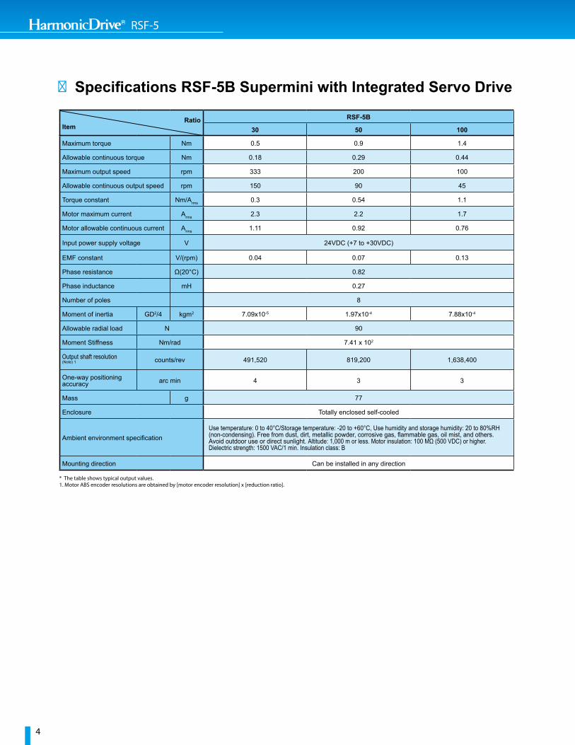
Maximum torque Nm 0.5 0.9 1.4
Allowable continuous torque Nm 0.18 0.29 0.44
Maximum output speed rpm 333 200 100
Allowable continuous output speed rpm 150 90 45
Torque constant Nm/Arms 0.3 0.54 1.1
Motor maximum current Arms 2.3 2.2 1.7
Motor allowable continuous current Arms 1.11 0.92 0.76
Input power supply voltage V 24VDC (+7 to +30VDC)
EMF constant V/(rpm) 0.04 0.07 0.13
Phase resistance Ω(20°C) 0.82
Phase inductance mH 0.27
Number of poles 8
Moment of inertia GD2/4 kgm2 7.09x10⁻⁵ 1.97x10⁻⁴ 7.88x10⁻⁴
Allowable radial load N 90
Moment Stiffness Nm/rad 7.41 x 10²
Output shaft resolution(Note) 1 counts/rev 491,520 819,200 1,638,400
One-way positioning accuracy arc min 4 3 3
Mass g 77
Enclosure Totally enclosed self-cooled
Ambient environment specificationUse temperature: 0 to 40°C/Storage temperature: -20 to +60°C, Use humidity and storage humidity: 20 to 80%RH(non-condensing). Free from dust, dirt, metallic powder, corrosive gas, flammable gas, oil mist, and others. Avoid outdoor use or direct sunlight. Altitude: 1,000 m or less. Motor insulation: 100 MΩ (500 VDC) or higher. Dielectric strength: 1500 VAC/1 min. Insulation class: B
Mounting direction Can be installed in any direction
* The table shows typical output values.1. Motor ABS encoder resolutions are obtained by [motor encoder resolution] x [reduction ratio].

5
RSA-8
■ Specifications RSA-8A Mini with Integrated Servo Drive
RatioItem
RSA-8A
30 50 100
Maximum torque Nm 1.8 3.3 4.8
Allowable continuous torque Nm 0.7 1.2 2.0
Maximum output speed rpm 283.3 170.0 85.0
Allowable continuous output speed rpm 116.7 70.0 35.0
Torque constant Nm/Arms 0.7 1.2 2.0
Motor maximum current Arms 4.0 4.0 3.5
Motor allowable continuous current Arms 2.05 2.0 1.7
Input power supply voltage V 24VDC (+7 to +30VDC)
EMF constant V/(rpm) 0.051 0.085 0.170
Phase resistance Ω(20°C) 0.8
Phase inductance mH 0.285
Number of poles 14
Moment of inertia GD2/4 kgm2 7.74x10⁻⁴ 2.15x10⁻³ 8.60x10⁻³
Allowable moment load Nm 3.46
Moment Stiffness Nm/rad 2.76 x 10³
Output shaft resolution(Note) 1 counts/rev 491,520 819,200 1,638,400
One-way positioning accuracy arc min 2 2 2
Mass g 200 (190 with F option)
Enclosure Totally enclosed self-cooled
Ambient environment specificationUse temperature: 0 to 40°C/Storage temperature: -20 to +60°C, Use humidity and storage humidity: 20 to 80%RH Free from dust, dirt, metallic powder, corrosive gas, flammable gas, oil mist, and others. Avoid outdoor use or direct sunlight. Altitude: 1,000 m or less. Motor insulation: 100 MΩ (500 VDC) or higher. Dielectric strength: 1500 VAC/1 min. Insulation class: B
Mounting direction Can be installed in any direction
* The table shows typical output values.1. Motor ABS encoder resolutions are obtained by [motor encoder resolution] x [reduction ratio].

6
RSF-5
■ RSF-5B Supermini Outline Dimensions
Cable housing dimensions and mounting dimensions are the same for both PT options. ■ RSF-5B Exit OptionsKey• PT1 Pigtail cable, rear
exit (opposite output)
• PT5 Pigtail cable, front exit
PT1 Rear Exit PT5 Front Exit
PT5 front exit cable
[mm]
THIS DRAWING CONTAINS VALUABLE CONFIDENTIAL AND PROPRIETARY TRADE SECRET INFORMATION OF HARMONIC DRIVE LLC. COPYING, DISCLOSING, ORUSING THIS INFORMATION WITHOUT THE EXPRESS WRITTEN AUTHORIZATIONOF HARMONIC DRIVE LLCIS PROHIBITED
PROPRIETARY AND CONFIDENTIAL
MATERIAL: REVDWG. NO.
DSIZE
TITLE:
34519FSCM
HARMONIC DRIVE LLC247 LYNNFIELD STREETPEABODY MASS 01960-4905www.harmonicdrive.net
ISSUE DATE
CONTRACT NO.
SUBMITTED
SIMILAR TO
BLANK - SHAFT OUTPUT F - FLANGE OUTPUT
PART DESCRIPTION
PTRSF-5B-XXX-IDT14b-
RATIO:3050
CABLE CONFIGURATION: PT1 - REAR
100
PT5 - FRONT
25
25
4.6
3X M2X0.4
9.8
3
2X 2.3
22 ±0.5 6
1
2
4
3
CANopen STATUS LED 8.
10.4
9
NOTES:
INTEGRATED ACTUATOR WITH WITH 24VDC (7VDC-28VDC) SUPPLY, ENCODER RESOLUTION: 14 BIT AT 1.INPUT (14 BIT*RATIO AT OUTPUT)
DESIGN AND/OR HANDLING MUST BE IN COMPLIANCE WITH TECHNICAL INFORMATION FOUND IN THE 2.HD RSF-SUPERMINI CATALOG
DIMENSIONS SHOWN IN MILLIMETERS3.
WEIGHT WITHOUT CABLE ASSEMBLY: 55 1g4.
ACTUATOR P/N 79-05XXXIDT14__PT 5. XXX IS THE RATIO WITH 030 FOR 30:1, 050 FOR 50:1, 100 FOR 100:1, __ IS BLANK FOR SHAFT OUTPUT, F FOR FLANGE OUTPUT PT IS THE CABLE CONFIGURATION, PT1 FOR REAR OR PT5 FOR FRONT
REPLACEMENT CABLE ASEMBLY PART NUMBERS:6. CONFIGURATION 1 AND 3, PT1 - 7318290 CONFIGURATION 2 AND 4, PT5 - 7318291
CUSTOMER CAD FILE:7. CONFIGURATION 1: U2-19050 CONFIGURATION 3: U2-19052 CONFIGURATION 2: U2-19051 CONFIGURATION 4: U2-19053
TYPICAL FOR ALL CONFIGURATIONS8.
REVISIONS
REV ECA NO. BY CHKD APPD DATE
91/9/7YRANIMILERPGAJ1
9102/32/7GAJ2
9102/6/11GAJ3
A 19-0986 JAG SNB BPC 1/8/2020
B 20-0436 JAG JP BPC 7/8/2020
C 20-0960 JAG AIZ BPC 11/19/2020
CONFIGURATION 2: FLANGE OUTPUT WITH PT5 FRONT FACING CABLES
CONFIGURATION 3: SHAFT OUTPUT WITH PT1 REAR FACING CABLES
CONFIGURATION 4: SHAFT OUTPUT WITH PT5 FRONT FACING CABLES
POWER AND COMMUNICATION CONNECTOR
LEMO PHL.0T.304.CYCC50
PIN SIGNAL
1 +24VDC
2 CANH
3 CANL
4 0VDC
35.8
1.7
13.8
+0
12.7
00.008
20
18.5
-20.5 h7
5.5
0.5
14.9
0.021
0-20.5 h7 0.021
13
2
0.3
5H6
200 + 350
JAG
WEIGHT: 55gSCALE: 2:1
DN PDR QUALITY
bcoyne 02/03/2021
7377849 REV B MARKETING BROCHURE DIMEN
CHECKER
SHEET 1 OF 1
SNB
MFG. ENG.
DRAFTSMAN
PT
B
THB INSTALLATION DRAWINGRSF-5B-XXX-IDT14b-
MAT'L ENG DESIGN ENG
1
E
F
E
D
C
B
AA
B
C
D
12345678
8 7 6 5 4 3 2
F
13.8 0.3 0.5
20
CONFIGURATION 1: FLANGE OUTPUT WITH PT1 REAR FACING CABLES
3
9.8
6
3X M2X0.4 2X 2.3
0.3 13.8 200 0
+35 0.5
20
6
6
2
0
20
0.3 0.5
9
13
5.5
35.8 12.7
13.8
5 h6 -
18.5
0.008
10
14.9 200 0
+ 35
22 ±0.5
200 0+35
38
9.5
PT5 front exit cable
SHAFT OUTPUTPT1 rear exit cable
FLANGE OUTPUTPT1 rear exit cable

7
RSA-8
■ RSA-8A Mini Outline Dimensions
THIS DOCUMENT WAS CREATED IN ACCORDANCE WITH ASME Y14.5-2018. THIS DRAWING CONTAINS
VALUABLE CONFIDENTIAL AND PROPRIETARY TRADE SECRET INFORMATION OF HARMONIC DRIVE LLC. COPYING, DISCLOSING, ORUSING THIS INFORMATION WITHOUT THE EXPRESS WRITTEN AUTHORIZATIONOF HARMONIC DRIVE LLCIS PROHIBITED.
REVSIMILAR TO
42 DUNHAM RIDGEBEVERLY MA 01915-1844www.harmonicdrive.net
CAGE CODE
34519
PROPRIETARY AND CONFIDENTIAL
TITLE:
SIZE
DDWG. NO.
THIRD ANGLE
DIMENSIONS ARE IN MILLIMETERS UNLESS OTHERWISE SPECIFIED.
35
35
NOTES:
INTEGRATED ACTUATOR WITH WITH 24VDC (7VDC-28VDC) SUPPLY, ENCODER1.
THERE IS NO RELATION BETWEEN M3 HOLES AND "D" CUT ON SHAFT
3. DIMENSIONS SHOWN ARE IN MILLIMETERS
4. DESIGN AND/OR HANDLING MUST BE IN COMPLIANCE WITH TECHNICAL INFORMATION FOUND IN THE HD CATALOG
5. WEIGHT WITHOUT CABLE ASSEMBLY 194g
6. CUSTOMER CAD MODELS CONFIGURATION 1: CONFIGURATION 2: PT1 - U2-19058 PT1 - U2-19054 PT2 - U2-19059 PT2 - U2-19055 PT3 - U2-19060 PT3 - U2-19056 PT5 - U2-19061 PT5 - U2-19057
7. RECOMMENDED MATING CABLE ORDERED SEPARATELY. PART NUMBER 7318232-ZZ WITH -ZZ BEING THE LENGTH IN METERS. STANDARD OPTIONS ARE -03, -05,AND -10 WITH CUSTOM LENGTHS AVAILABLE IN 1 METER INCREMENTS
2.
REVISIONS
REV ECA NO. CHANGE BY CHKD APPD DATE
91/9/7GAJ1
2
CHG CONNECTOR FROM FGL TO
PHL9102/32/7GAJ
9102/11/11GAJETADPU3
A 19-0982 RELEASE JAG SNB BPC 12/20/19
0202/31/3CABNSGAJ0410-02B
0202/82/5CPBBNSGAJ1130-02C
D 20-0968 ADD LED JAG AIZ BPC 12/10/2020
CONFIGURATION 1: SHAFT OUTPUTSHOWN WITH PT5 FRONT FACING CABLES
CONFIGURATION 2: FLANGE OUTPUTSHOWN WITH PT5 FRONT FACING CABLES
OPTIONAL PT (PIGTAIL) CABLE CONFIGURATIONS
MATING VIEW
POWER AND COMMUNICATION CONNECTOR LEMO PHL.0T.304.CYCK55
PIN SIGNAL
1 +24VDC
2 CANH
3 CANL
4 0VDC
CABLE CONFIGURATION: PT1 - REAR PT2 - RIGHT PT3 - LEFT PT5 - FRONT
RATIO:3050
100
PART DESCRIPTION
RSA-8A-XXX-IDT14b- PM
BLANK - SHAFT OUTPUT F - FLANGE OUTPUT
CONFIGURATION NUMBER PART NUMBERS AND APPROPRIATE MARKINGS
HDLLC P/N RATIO OUTPUT TYPE
XXX
1 114-08030IDT14bPT 30 SHAFT
1 114-08050IDT14bPT 50 SHAFT
1 114-08100IDT14bPT 100 SHAFT
2 114-08030IDT14bFPT 30 FLANGE
2 114-08050IDT14bFPT 50 FLANGE
2 114-08100IDT14bFPT 100 FLANGE
62X M3X0.5
8
15.5
40
44X M3X0.5 -6H
30.7±0.5
CHECKER
12/18/2019QUALITYJAG
JAG 07/09/2019
SCALE: 2:1
7377853NS 12/19/2019
PT
SHEET 1 OF 1
MFG. ENG.PDR 12/19/2019
MAT'L ENG.THB 12/19/2019
SNB 12/18/2019 INSTALLATION DRAWINGRSA-8A-XXX-IDT14b-DESIGN ENG.
DRAFTER
D
2
1
A A
B B
C C
D D
E E
F F
8
8
7
7
6
6
5
5
4
4
3
3
2
1
2.5 0.5
20
0.021
18
-00.009
76.5
9 h6
20 56.5±0.5
30±0.5
10.2
0
5.1
29 h7 -
26
30±0.5
2 26
4
40
4X M3X0.5 -6H
2X M3X0.5 6
15.5
30.7±0.5
+0.0150
5.1
56.5±0.5
30±0.5 20
2.2
0.5
9 H7
0.5 X 45.00°
10.2
2.5
29 h7 -00.021
26
30±0.5
2 26
PT3PT2
PT1
PT5 (PREFERRED)
23
1
KEY LOCATIONS
4
CANopen STATUS LED
15
13.5
CANopen STATUS LED
15
13.5
9.5
38
200 + 350
SHAFT OUTPUTPT5 front exit cable
Cable housing dimensions and mounting dimensions are the same for all PT options. ■ RSA-8A Exit OptionsKey• PT1 Pigtail cable, rear
exit (opposite output)
• PT2 Pigtail cable, right exit (of output side)
• PT3 Pigtail cable, left exit (of output side)
• PT5 Pigtail cable, front exit
PT1 Rear Exit PT2 Right Exit PT3 Left Exit PT5 Front Exit
THIS DOCUMENT WAS CREATED IN ACCORDANCE WITH ASME Y14.5-2018. THIS DRAWING CONTAINS
VALUABLE CONFIDENTIAL AND PROPRIETARY TRADE SECRET INFORMATION OF HARMONIC DRIVE LLC. COPYING, DISCLOSING, ORUSING THIS INFORMATION WITHOUT THE EXPRESS WRITTEN AUTHORIZATIONOF HARMONIC DRIVE LLCIS PROHIBITED.
REVSIMILAR TO
42 DUNHAM RIDGEBEVERLY MA 01915-1844www.harmonicdrive.net
CAGE CODE
34519
PROPRIETARY AND CONFIDENTIAL
TITLE:
SIZE
DDWG. NO.
THIRD ANGLE
DIMENSIONS ARE IN MILLIMETERS UNLESS OTHERWISE SPECIFIED.
35
35
NOTES:
INTEGRATED ACTUATOR WITH WITH 24VDC (7VDC-28VDC) SUPPLY, ENCODER1.
THERE IS NO RELATION BETWEEN M3 HOLES AND "D" CUT ON SHAFT
3. DIMENSIONS SHOWN ARE IN MILLIMETERS
4. DESIGN AND/OR HANDLING MUST BE IN COMPLIANCE WITH TECHNICAL INFORMATION FOUND IN THE HD CATALOG
5. WEIGHT WITHOUT CABLE ASSEMBLY 194g
6. CUSTOMER CAD MODELS CONFIGURATION 1: CONFIGURATION 2: PT1 - U2-19058 PT1 - U2-19054 PT2 - U2-19059 PT2 - U2-19055 PT3 - U2-19060 PT3 - U2-19056 PT5 - U2-19061 PT5 - U2-19057
7. RECOMMENDED MATING CABLE ORDERED SEPARATELY. PART NUMBER 7318232-ZZ WITH -ZZ BEING THE LENGTH IN METERS. STANDARD OPTIONS ARE -03, -05,AND -10 WITH CUSTOM LENGTHS AVAILABLE IN 1 METER INCREMENTS
2.
REVISIONS
REV ECA NO. CHANGE BY CHKD APPD DATE
91/9/7GAJ1
2
CHG CONNECTOR FROM FGL TO
PHL9102/32/7GAJ
9102/11/11GAJETADPU3
A 19-0982 RELEASE JAG SNB BPC 12/20/19
0202/31/3CABNSGAJ0410-02B
0202/82/5CPBBNSGAJ1130-02C
D 20-0968 ADD LED JAG AIZ BPC 12/10/2020
CONFIGURATION 1: SHAFT OUTPUTSHOWN WITH PT5 FRONT FACING CABLES
CONFIGURATION 2: FLANGE OUTPUTSHOWN WITH PT5 FRONT FACING CABLES
OPTIONAL PT (PIGTAIL) CABLE CONFIGURATIONS
MATING VIEW
POWER AND COMMUNICATION CONNECTOR LEMO PHL.0T.304.CYCK55
PIN SIGNAL
1 +24VDC
2 CANH
3 CANL
4 0VDC
CABLE CONFIGURATION: PT1 - REAR PT2 - RIGHT PT3 - LEFT PT5 - FRONT
RATIO:3050
100
PART DESCRIPTION
RSA-8A-XXX-IDT14b- PM
BLANK - SHAFT OUTPUT F - FLANGE OUTPUT
CONFIGURATION NUMBER PART NUMBERS AND APPROPRIATE MARKINGS
HDLLC P/N RATIO OUTPUT TYPE
XXX
1 114-08030IDT14bPT 30 SHAFT
1 114-08050IDT14bPT 50 SHAFT
1 114-08100IDT14bPT 100 SHAFT
2 114-08030IDT14bFPT 30 FLANGE
2 114-08050IDT14bFPT 50 FLANGE
2 114-08100IDT14bFPT 100 FLANGE
62X M3X0.5
8
15.5
40
44X M3X0.5 -6H
30.7±0.5
CHECKER
12/18/2019QUALITYJAG
JAG 07/09/2019
SCALE: 2:1
7377853NS 12/19/2019
PT
SHEET 1 OF 1
MFG. ENG.PDR 12/19/2019
MAT'L ENG.THB 12/19/2019
SNB 12/18/2019 INSTALLATION DRAWINGRSA-8A-XXX-IDT14b-DESIGN ENG.
DRAFTER
D
2
1
A A
B B
C C
D D
E E
F F
8
8
7
7
6
6
5
5
4
4
3
3
2
1
2.5 0.5
20
0.021
18
-00.009
76.5
9 h6
20 56.5±0.5
30±0.5
10.2
0
5.1
29 h7 -
26
30±0.5
2 26
4
40
4X M3X0.5 -6H
2X M3X0.5 6
15.5
30.7±0.5
+0.0150
5.1
56.5±0.5
30±0.5 20
2.2
0.5
9 H7
0.5 X 45.00°
10.2
2.5
29 h7 -00.021
26
30±0.5
2 26
PT3PT2
PT1
PT5 (PREFERRED)
23
1
KEY LOCATIONS
4
CANopen STATUS LED
15
13.5
CANopen STATUS LED
15
13.5
9.5
38
200 + 350
FLANGE OUTPUTPT5 front exit cable
[mm]

RSF-5
8
■ Operating Range
■ RSF-5B-30
0.3
0.2
0.4
0.5
0.6
0.0
0.1
0 50 100 150 200 250 300 350
■ RSF-5B-50
0.2
0.4
0.6
1.0
0.8
0.00 50 100 150 200 250
■ RSF-5B-100
1.5
0.0
0.3
0.9
0.6
1.2
0 20 40 60 80 100 120
Rotational Speed [rpm]
Torq
ue [N
m]
Aluminum heatsink: 150×150×3(mm)
Rotational Speed [rpm]
Torq
ue [N
m]
Aluminum heatsink: 150×150×3(mm)
Rotational Speed [rpm]
Torq
ue [N
m]
Aluminum heatsink: 150×150×3(mm)
Acceleration/ deceleration motion range
Acceleration/ deceleration motion range
Acceleration/ deceleration motion range
Acceleration/ deceleration motion range
Acceleration/ deceleration motion range
Acceleration/ deceleration motion range
Continuous motion rangeContinuous motion range
Continuous motion rangeContinuous motion range
Continuous motion rangeContinuous motion range
50% duty motion range
50% duty motion range
50% duty motion range
50% duty motion range
50% duty motion range
50% duty motion range
24V
24V
24V
The graphs show the operating range for RSF-5 and RSA-8 Mini Series actuators with an integrated drive.
■ Continuous Motion Range The range allows continuous operation of the actuator.
■ 50% Duty Motion Range This range indicates the torque/speed where 50% duty cycle operation is permitted (the ratio of operating time and delay time is 50:50).
■ Motion Range During Acceleration and Deceleration This range indicates the torque/speed which the actuator can be operated momentarily. The range allows instantaneous operation such as during acceleration and deceleration.
The continuous and 50% duty motion ranges shown on each graph are measured when the actuator is mounted to an aluminum heatsink as specified.
0 50 100 150 200 250 300Rotational Speed [rpm]
Torq
ue [N
m]
■ RSA-8A-30Aluminum heatsink: 150×150×6(mm)
0.6
0.4
0.8
1
1.2
1.41.6
1.8
2
0
0.2
0 50 100 150 200Rotational Speed [rpm]
Torq
ue [N
m]
■ RSA-8A-50Aluminum heatsink: 150×150×6(mm)
1
1.5
2
2.5
3
3.5
0
0.5
Acceleration/ deceleration motion range
Acceleration/ deceleration motion range
Continuous motion rangeContinuous motion range
50% duty motion range
50% duty motion range
0 20 40 60 80 100Rotational Speed [rpm]
Torq
ue [N
m]
■ RSA-8A-100Aluminum heatsink: 150×150×6(mm)
2
3
4
5
6
0
1
Acceleration/ deceleration motion range
Acceleration/ deceleration motion range
Continuous motion rangeContinuous motion range
50% duty motion range
50% duty motion range
Acceleration/ deceleration motion range
Acceleration/ deceleration motion range
Continuous motion rangeContinuous motion range
50% duty motion range
50% duty motion range
24V
24V
24V

9
RSA-8
Size
Pitch Circle Offset Basic Rated Load Allowable moment
loadMoment stiffness
Allowable radial load
Allowable axial loaddp R Basic dynamic rated load Basic static rated load
mm mm ×102 N ×102 N Nm Nm/rad N N
5 13.5 4.85 9.14 7.63 0.89 7.41×10² 90 2708 20.5 7.3 21.6 19.0 3.46 2.76×10³ 200 630
■ One-Way Positional Accuracy
■ Output Bearing Specifications
The one-way positioning accuracy is defined as the maximum positional difference between the commanded position and the actual stop position when a series of positioning moves are performed in the same rotation direction. (Refer to JIS B-6201-1987).
The RSF Supermini actuator incorporates a Harmonic Drive® gear which inherently has high-rotational position accuracy. Because of the gearing's high ratio, any rotational error at the input (i.e. motor shaft position error or motor feedback error) is reduced by a factor of the ratio (1/ratio) and typically becomes negligible at the output. Therefore most of the error is represented by the transmission error of the Harmonic Drive gear itself.
Commanded stop position
Actual stop position
Positioning error
Datum position
Size
Item
RSF-5B RSA-8A
30 50 100 30 50 100
One-Way Positional Accuracy
arc min 4 3 3 2 2 2
rad 1.20×10⁻³ 0.87×10⁻³ 0.87×10⁻³ 5.82 x 10⁻⁴ 5.82 x 10⁻⁴ 5.82 x 10⁻⁴
One-Way Positioning Accuracy
* The value of the moment stiffness is the average value.

RSF-5
10
■ HDL-IDE 3.0 Software:
Velocity Mode Position Mode
Torque ModeBode Plot and Settings
Features• Torque Mode and Graph• Velocity Mode and Graph• Position Mode and Graph• Homing Mode • Limit Switch • Current Position • Hardstop Homing• Step Response• Bode Plot• Parameter List• Virtual Mode (shown)
HDL-IDE 3.0 software provides the ability to setup or commission the RSF-5B and RSA-8A Integrated actuator without connecting to a CANopen master controller. A single actuator can connect to a personal computer or laptop with a CAN communication converter, a termination resistor and a power supply. All 256 parameters, including the tuning parameters and 256 general user variables can be set and stored to be recognized by the CANopen master controller operating the specific application. The following are some of the features included in HDL-IDE 3.0 software:

11
RSA-8
■ Actuators with an Integrated Servo Drive An integrated actuator from Harmonic Drive eliminates the need for a separate servo drive to be connected to the system. RSF-5B-IDT and RSA-8A-IDT join the new Integrated Actuator product category, along with 3 models of FHA-IDT, sizes 8, 11 and 14.
• Mitigates cable management concerns• No encoder cables connected to the servo drive and therefore
no wire harnesses or cable tracks and associated electrical noise concerns
• Reduction in number of potential failures with less connections• Simplifies the control hardware saving cabinet space• Eliminate the need for a separate drive• Matched motor and drive for optimal performance and simple
system integration• Lower complete solution cost with less cabling and installation
time
The functionality of a full size servo drive is seamlessly integrated into a mini actuator from Harmonic Drive.
The Servo Drive is Inside!
FHA-C Mini Actuator with Servo Drive

Rev 20210830
■ All efforts have been made to ensure that the information in this catalog is complete and accurate. However, Harmonic Drive LLC is not liable for any errors, omissions or inaccuracies in the reported data. Harmonic Drive LLC reserves the right to change the product specifications, for any reason, without prior notice. © 2021 Harmonic Drive. All rights reserved.
Harmonic Drive LLCBoston US Headquarters42 Dunham Ridge Beverly, MA 01915978.532.1800 www.HarmonicDrive.net
New York Sales Office100 Motor Parkway, Suite 116Hauppauge, NY 11788
California Sales Office333 W. San Carlos Street, Suite 1070San Jose, CA 95110
Chicago Sales Office137 N. Oak Park Ave., Suite 410Oak Park, IL 60301
Group CompaniesHarmonic Drive Systems, Inc. 6-25-3 Minami-Ohi, Shinagawa-ku Tokyo 141-0013, JapanHarmonic Drive SEHoenbergstrasse, 14, D-65555Limburg/Lahn Germany
Harmonic Drive is a registered trademark of Harmonic Drive LLC. CANopen is a registered trademark of CAN in Automation. LEMO is a registered trademark of INTERLEMO HOLD-INGS.