two part assembly
TRANSCRIPT

BETA CAE Systems S.A.
Tutorial 2
TWO PART ASSEMBLY
FROM IGES TO
NASTRAN FE-MODEL
Table of Contents
2.1. Introduction .................................................................................................................................2
2.1.2. Prerequisites .......................................................................................................................2
2.1.3. Problem description.............................................................................................................2
2.1.4. Data files .............................................................................................................................2
2.2. Read the CAD data .....................................................................................................................3
2.3. Merge the parts to form the assembly.........................................................................................6
2.4. Clean-up the geometry................................................................................................................9
2.5. Prepare the geometry for meshing............................................................................................15
2.6. Create compatible flanges using Linked Faces ........................................................................23
2.7. Create mesh dependant connections .......................................................................................29
2.8. Mesh the assembly ...................................................................................................................34
2.9. Examine the quality of the mesh...............................................................................................40
2.10. Create mesh independent connections ..................................................................................43
2.11. Define loads and constraints...................................................................................................46
2.12. Define the HEADER................................................................................................................52
2.13. Output the NASTRAN FE-model.............................................................................................56
2.14. Conclusion ..............................................................................................................................57

TWO PART ASSEMBLY - From IGES to NASTRAN FE-Model
BETA CAE Systems S.A. Tutorial 2 - 2 ANSA v.12.0.1 Tutorials
2.1. Introduction
This tutorial presents in detail all the steps taken to model a two-part T-junction, starting from importing the CAD data of the parts into ANSA, to NASTRAN FE-model output. The steps described in this tutorial include:
• Reading the IGES files of each part separately and saving in ANSA format.
• Opening a new empty ANSA database and merging the two parts to form the assembly.
• Managing the assembly using the Part Manager.
• Cleaning up geometry, removing small holes and other details.
• Offsetting to the middle skin.
• Creating linked flanges for compatible mesh.
• Creating connection points from existing positions and new ones.
• Manage connection points and create mesh dependant spot weld connections
• Mesh the parts with an element length of 20 mm
• Check mesh for penetration and quality
• Create mesh independent spot weld connections
• Define loads and constraints for two different subcases
• Create the NASTRAN header
• Output the NASTRAN file.
2.1.2. Prerequisites
Reading the 4 pages of section Intro.2.1. Getting Started of this Guide, as well as performing Tutorial 1, is recommended in order to obtain a familiarization with the ANSA interface and terminology. Some basic knowledge of the NASTRAN solver is also suggested.
2.1.3. Problem description
The case consists of the assembly shown below. It consists of two metal sheet parts with the given specifications:
PartA module ID: 100 PID: 10 sheet t=0.8mm MID: 1 steel
PartB module ID: 200 PID: 20 sheet t=1.2mm MID: 1 steel
Loads 50 N at each node axial force 25 N at each node shear force
Constraints No xyz translation at one end No yz translation at the other end
The two different loadings are applied in separate Subcases. The constraints are the same for both Subcases.
2.1.4. Data files
The files required for this tutorial are located in the directory tutorial_files/02-shell_assy.
They are two IGES files named partA.igs and partB.igs . The result can be found for
reference in the file assembly.ansa .
loads
constraints

TWO PART ASSEMBLY - From IGES to NASTRAN FE-Model
BETA CAE Systems S.A. Tutorial 2 - 3 ANSA v.12.0.1 Tutorials
2.2. Read the CAD data
Start ANSA.
By default you are in the TOPO menu.
Before reading any CAD data into ANSA you can specify some settings concerning the application of Topology, and the Resolution, that is the appearance of geometrical entities on the screen. These settings should correspond to the dimensions, level of detail and tolerances of the CAD file to be input.
By default, the Topology (the connectivity of adjacent Faces) is performed during CAD file opening (this depends on the flag button under SETTINGS> ACTIV.TOPO in the main
pull-down menu at the top). As a result when you read the IGES files later on, the topology will be performed. De-activate Geom CleanUp.
Note that the automatic topology is performed according to the tolerance settings that are specified in SETTINGS>TOLERANCES. Make sure to specify appropriate tolerance
values before reading a CAD file, to avoid collapsed Faces (large tolerances), or gaps (very small tolerances). In this example activate the SETTINGS> TOLERANCES function, select middle tolerance settings (Nodes 0.05, Curves 0.2) and press OK.
Also note that the appearance of geometrical details depends on the Resolution settings
under RESOLUTION in the main pull-down menu. Activate the function, press OK in the Warning window, and the Resolution Definition window appears. In this case, as the parts will be meshed with an element length of 20 mm, enter 20 for CONS resolution. For 3D Curves specify a smaller resolution (2) to view small geometrical features in more detail. Press OK to close the window. (Ensure also that you have the default distance distortion of 20% in
the MESH>PERIMETERs>DISTOR function).
Now read in the IGES data from FILE>OPEN. The File Manager window appears. Specify a filter (*igs in this
case), navigate and select the IGES file partA.igs.
Press OK to read the CAD data.
SETTINGS
ACTIV. TOPO
RESOLUTION
SETTINGS
TOLERANCES

TWO PART ASSEMBLY - From IGES to NASTRAN FE-Model
BETA CAE Systems S.A. Tutorial 2 - 4 ANSA v.12.0.1 Tutorials
Before saving in ANSA format, ensure that the part has correct module ID, PID and MID assigned to it.
Press the PR.LIST button (bottom center location).
The Properties window appears.
One property exists with ID=1. Select it from the list with the left mouse button and it becomes marked in black. Press EDIT to open the Property card and modify its specifications.
Place the mouse cursor in the respective fields and type in: Property name: sheet t=0.8mm
PID: 10 T, (thickness): 0.8 At the end press the OK button.
Press the ESC key to exit from the Properties List window.
Press the M.LIST button (just below the PR.LIST
button), to open the Materials window. Select with the left mouse button the
"Default MAT1 Material" with
ID=1 and press EDIT.
PR.LIST
M.LIST
Esc

TWO PART ASSEMBLY - From IGES to NASTRAN FE-Model
BETA CAE Systems S.A. Tutorial 2 - 5 ANSA v.12.0.1 Tutorials
The Material card appears. Place the cursor in the respective field and type in
the required name ("steel") and
values
(E, ρ, ν etc.).
Press OK to confirm and close the card.
Press the ESC key to exit from the Materials List window.
Finally, press the PARTS button, to open the Part
Manager. One part exists with the name of the CAD file that was read. Right-click on the thumbnail of the part and select Edit.
Specify the name and ID and confirm with OK.
Press the ESC key to exit from the Part Manager.
Note that all this information could have been automatically passed to the ANSA database from the IGES file, provided that the use of the ANSA_TRANSL had been implemented (see User’s Guide).
Now you can save in ANSA format.
Select FILE>SAVE AS to save the part in ANSA database. Use the File Manager to select a path and a name. Make sure to type in the extension .ansa in the
filename.
Repeat the same procedure for the IGES file partB.igs . Open the IGES file from FILE>OPEN.
Open the Property List window, EDIT the Property and specify PID=20 with name "sheet
t=1.2mm" and thickness 1.2. Open the Materials List, EDIT the Material and specify MID=1 with
name "steel". Finally Open the Part Manager and Edit the Part, specifying name "partB", and
Module ID 200, and save it in ANSA format as partB.ansa from FILE>SAVE AS.
Note that for multiple CAD files you can use the FILE>AUTO command, where you can select more than one CAD files and let ANSA perform the translation and save them as ANSA databases with their initial name and with the .ansa extension.
PARTS
Edit
Esc

TWO PART ASSEMBLY - From IGES to NASTRAN FE-Model
BETA CAE Systems S.A. Tutorial 2 - 6 ANSA v.12.0.1 Tutorials
2.3. Merge the parts to form the assembly
Open a new empty ANSA database from FILE>NEW.
Then select FILE>MERGE to merge the two previously saved ANSA databases in one, and create the assembly.
Select from the File Manager the ANSA databases to be merged.
In the Merge Parameters window that appears, de-activate the Offset flag of MIDs. The two databases have different PIDs (10 and 20) so there is no need for offset, but both have an MID of 1 which represents the same material. By de-activating the MID offset flag, the MID of the two databases will be merged into a single one as required. Press OK.
Activate SHADOW mode to view the assembly.
By default you are in ENT mode so the Faces should
appear as shown gray or yellow depending on their orientation.
Remember that the visibility of different entities is controlled by the respective flag. Activate CURVEs and POINTs.
By deactivating the FACEs flag you can observe clearly the 3D Curves and 3D Points, which are there to help you recognize small geometrical features (remember the smaller resolution setting for Curves).
SHADOW
ENT..
NEW
FILE

TWO PART ASSEMBLY - From IGES to NASTRAN FE-Model
BETA CAE Systems S.A. Tutorial 2 - 7 ANSA v.12.0.1 Tutorials
You can check the Properties and Materials that participate in this database.
Open the Part Manager.
There is one empty “Untitled” part, present by default in the new empty database that you have created, and two Groups, one for each ANSA database that was merged, and named after it. Groups, indicated by the folder symbol at the top left corner of the thumbnails, contain Parts in them.
To view the contents of a Group right-click on the thumbnail of a Group and select Open.
(Note that the Current Part window also appears, displaying the Untitled part as Current by default) A new window opens displaying the contents of the selected Group. As expected there is one Part named
"partA". Right-click on the Part and select Edit to
view its name and Module ID.
Keeping the Shift key pressed select with the left mouse button the two Groups. The Selected
Groups are marked in a black box. Release the Shift key, press right click and select Ungroup from the popup menu.
Confirm by pressing OK.
PR. LIST
M. LIST
PARTS
Open
Edit
Shift
Ungroup

TWO PART ASSEMBLY - From IGES to NASTRAN FE-Model
BETA CAE Systems S.A. Tutorial 2 - 8 ANSA v.12.0.1 Tutorials
Open the Part Manager again.
Note that the two Parts (A and B) have been placed at the top level of the Part Manager and the Groups are now empty.
Right-click on "PartA" and select
Current. Now you can delete the empty Parts and Groups by pressing on CLEAR.
Finally, press ARRANGE to line up all the Part thumbnails.
Note that you cannot remove an empty Part if it is marked as Current, that is why
"partA" was set as Current.
Press the ESC key to exit from the Part Manager.
Note that you can press the AB button of the Part Manager to sort the Parts in an alphabetical order if
they are not.
You can now save the assembly in ANSA format, in which you can work. Select FILE>SAVE AS and assign the filename assembly.ansa.
Note that: The current Part name appears at the top of the display and the filename appears at the bottom left.
PARTS
Current
A
B
Esc

TWO PART ASSEMBLY - From IGES to NASTRAN FE-Model
BETA CAE Systems S.A. Tutorial 2 - 9 ANSA v.12.0.1 Tutorials
2.4. Clean-up the geometry
This step consists of the identification and repair of problematic topology region of the model. Note that for a complicated assembly with many parts, this step would probably have been performed separately in the ANSA database of each part.
Switch to PID view mode to view the Parts with their PID color and distinguish them easily.
Note that colors may be different, as they are randomly selected. You can modify the PID colors from the Property List, by selecting a property, clicking on EDIT, and pressing ColorEdit in the Property card that appears.
However, in this case you will use the functionality of the Part Manager to isolate a Part, and work
on one at a time. Start working on "PartA".
Open the Part Manager.
Right-click on the thumbnail of partA and select Lock. The Part becomes highlighted in yellow.
Press the ESC key to exit from the Part Manager.
From now on, when you activate the ALL function of the FOCUS
group of commands only this part will appear, and not the whole assembly.
Lock
PARTS
ALL
Esc
TWO PART ASSEMBLY - From IGES to NASTRAN FE-Model
BETA CAE Systems S.A. Tutorial 2 - 10 ANSA v.12.0.1 Tutorials
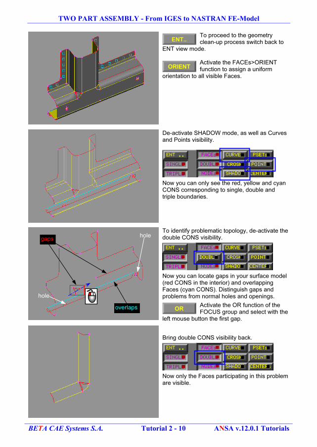
To proceed to the geometry clean-up process switch back to
ENT view mode.
Activate the FACEs>ORIENT function to assign a uniform
orientation to all visible Faces.
De-activate SHADOW mode, as well as Curves and Points visibility.
Now you can only see the red, yellow and cyan CONS corresponding to single, double and triple boundaries.
To identify problematic topology, de-activate the double CONS visibility.
Now you can locate gaps in your surface model (red CONS in the interior) and overlapping Faces (cyan CONS). Distinguish gaps and problems from normal holes and openings.
Activate the OR function of the FOCUS group and select with the
left mouse button the first gap.
Bring double CONS visibility back.
Now only the Faces participating in this problem are visible.
ORIENT
ENT..
gaps
overlaps OR
hole
hole
TWO PART ASSEMBLY - From IGES to NASTRAN FE-Model
BETA CAE Systems S.A. Tutorial 2 - 11 ANSA v.12.0.1 Tutorials
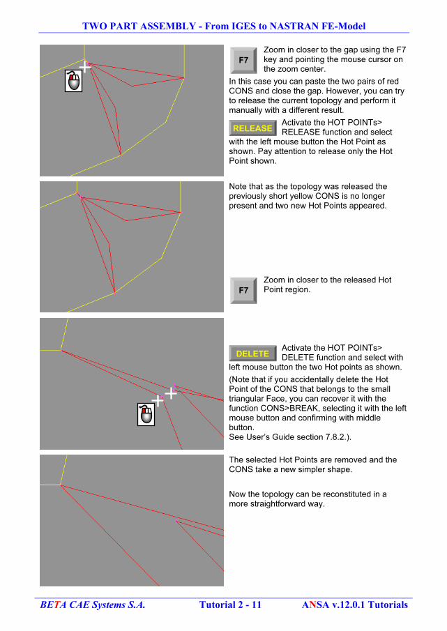
Zoom in closer to the gap using the F7 key and pointing the mouse cursor on the zoom center.
In this case you can paste the two pairs of red CONS and close the gap. However, you can try to release the current topology and perform it manually with a different result.
Activate the HOT POINTs> RELEASE function and select
with the left mouse button the Hot Point as shown. Pay attention to release only the Hot Point shown.
Note that as the topology was released the previously short yellow CONS is no longer present and two new Hot Points appeared.
Zoom in closer to the released Hot Point region.
Activate the HOT POINTs> DELETE function and select with
left mouse button the two Hot points as shown.
(Note that if you accidentally delete the Hot Point of the CONS that belongs to the small triangular Face, you can recover it with the function CONS>BREAK, selecting it with the left mouse button and confirming with middle button. See User’s Guide section 7.8.2.).
The selected Hot Points are removed and the CONS take a new simpler shape.
Now the topology can be reconstituted in a more straightforward way.
RELEASE
F7
DELETE
F7

TWO PART ASSEMBLY - From IGES to NASTRAN FE-Model
BETA CAE Systems S.A. Tutorial 2 - 12 ANSA v.12.0.1 Tutorials
Activate the CONS>PASTE function and select with the left
mouse button the CONS to be pasted.
Note the order of CONS selection. The first selected CONS is moved to match the second.
Note also that as the gap is relatively large and exceeds the current Tolerance settings a warning message appears. In this case confirm the operation by pressing OK.
Similarly paste the other pair of CONS together.
Now both CONS are yellow implying that the gap has been closed.
Press on the ALL function of the FOCUS group to bring all the
Faces of the Locked Part back.
Press the F10 key to zoom all in the standard isometric view.
Now you can move to the next problematic region.
Perform an OR selection to isolate the gap on the right.
Press the F9 key to zoom automatically to the current visible entities.
Paste the two red CONS together to close the gap.
PASTE
PASTE
ALL
OR
PASTE
1
2
2
F9
1 2
F10

TWO PART ASSEMBLY - From IGES to NASTRAN FE-Model
BETA CAE Systems S.A. Tutorial 2 - 13 ANSA v.12.0.1 Tutorials
Press on the ALL function of the FOCUS group to bring all the
Faces of the Locked Part back.
Press the F10 key to zoom all in the standard isometric view.
De-activate double CONS visibility
Zoom in closer to the cyan (triple) CONS region.
Activate crosshatch visibility.
You can see that in this region there are two overlapping Faces in the fillet region.
Use the SURFs>INFO function and select with the left mouse
button each Face from its crosshatch. You can thus obtain a preview of its Surface.
This Face has a planar Surface description.
Use the same function to inquire about the other Face.
This Face has a curved surface description and is more appropriate for the fillet.
ALL
F7
INFO
INFO
crosshatches
F10

TWO PART ASSEMBLY - From IGES to NASTRAN FE-Model
BETA CAE Systems S.A. Tutorial 2 - 14 ANSA v.12.0.1 Tutorials
Use the FACEs>DELETE function to delete the planar Face.
Select with the left mouse button its crosshatch. The Face is deleted and the cyan line disappears.
(Note that if you select a Face from one of its CONS, instead of its crosshatch, then a confirmation window opens and the Face to be deleted is previewed.)
Press the F10 key to zoom all to the standard isometric view and de-activate the crosshatch visibility.
The part seems now clean, without any gaps or overlapping Faces.
To perform the final check, activate double CONS visibility and SHADOW mode.
Note that the orientation, gray (positive) and yellow (negative), of the Faces can be altered using the MESH>MACROs>INVERT function, according to your preference.
Activate the UCHECKED function of the FOCUS group. This
function leaves only the Faces that failed the Shadow operation visible (unchecked).
No Faces remain visible, hence the part is clean.
Press ALL to recover the view of all the part.
Save the database from FILE>SAVE.
F10
UCHECKED
ALL
DELETE

TWO PART ASSEMBLY - From IGES to NASTRAN FE-Model
BETA CAE Systems S.A. Tutorial 2 - 15 ANSA v.12.0.1 Tutorials
2.5. Prepare the geometry for meshing
In this stage you will identify holes and openings and remove them, as they are too small to be included in your mesh model. You will also treat flanges and fillets. Finally you will offset the Faces to the middle skin so that the mesh will be generated there.
Notice that in this part there are two openings (detail view in blue boxes). With the Curves visibility on you can observe in more detail the shape of the openings. Remember that we have specified a smaller resolution for Curves (2mm) than for CONS (20mm).
In case you do not have Curves in your ANSA database to help you in the identification of such details, you can increase the resolution of the CONS at selected regions using the FINE function, located in the Geometry group. This group of functions is located at the bottom center of the ANSA GUI.
Activate the FINE function and left click on a CONS. Each left click
increases the resolution by a factor of 2.
Be aware that altering the resolution of a CONS in such a way has a direct effect on the local element length of the respective Perimeter Segment in the MESH menu.
To decrease the resolution use right-click.
To automatically identify and remove the holes present in the
part use the CONS>FILL HOL function. The Fill Hole Parameters window appears:
Specify a diameter of 10mm and press the Select button.
ANSA identifies all holes with diameter less than 10 and highlights them. Press OK to proceed with the removal of the identified hole.
FINE
FILL HOL

TWO PART ASSEMBLY - From IGES to NASTRAN FE-Model
BETA CAE Systems S.A. Tutorial 2 - 16 ANSA v.12.0.1 Tutorials
While still in the CONS>FILL HOL function, select with the left mouse button the internal perimeter shown.
The selected perimeter is highlighted. Press OK to proceed with the removal of the selected perimeter. Finally, press OK again or ESC to exit the function.
Next focus on the shape of the flanges. Notice how the corners of the lower flange of the part are rounded. To obtain a better mesh quality, these corners should preferably be sharp.
Activate the HOT POINTs> INSERT function and insert a Hot
Point with the left mouse button near the middle of the free CONS of the flange.
Next, zoom close to one such corner of the part.
Activate the FACEs>FLANGE [CORNER] function. Select AUTO mode in the Radius Definition window. Left-click
on the red free CONS on the curved region.
CORNER
FLANGE
INSERT
TWO PART ASSEMBLY - From IGES to NASTRAN FE-Model
BETA CAE Systems S.A. Tutorial 2 - 17 ANSA v.12.0.1 Tutorials
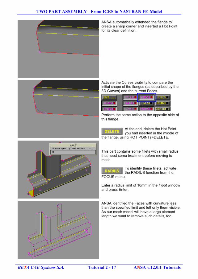
ANSA automatically extended the flange to create a sharp corner and inserted a Hot Point for its clear definition.
Activate the Curves visibility to compare the initial shape of the flanges (as described by the 3D Curves) and the current Faces.
Perform the same action to the opposite side of this flange.
At the end, delete the Hot Point you had inserted in the middle of
the flange, using HOT POINTs>DELETE.
This part contains some fillets with small radius that need some treatment before moving to mesh.
To identify these fillets, activate the RADIUS function from the
FOCUS menu. Enter a radius limit of 10mm in the Input window and press Enter.
ANSA identified the Faces with curvature less than the specified limit and left only them visible. As our mesh model will have a large element length we want to remove such details, too.
RADIUS
DELETE

TWO PART ASSEMBLY - From IGES to NASTRAN FE-Model
BETA CAE Systems S.A. Tutorial 2 - 18 ANSA v.12.0.1 Tutorials
De-activate Curves visibility.
Press ALL form the FOCUS menu to bring all the part back.
Use the FACEs>DACH [DIVIDE FACE] function to split the fillets in half.
Activate the function and select the fillet with the left mouse button from its free end (red CONS).
The fillet Face is highlighted and the Divide Parameters window opens. Activate the Join Macros flag so that after splitting of the fillet along its length the adjacent parallel CONS are joined and the split fillet is shared between the two adjacent large Macro Areas. Press OK.
Note that the fillet is split in half and a new yellow CONS appears along the middle. The two adjacent yellow CONS are now colored in brown as they are joined. Switch to MESH menu to view the correspondence.
Use the DACH [DIVIDE FACE] function on all small fillets at the other two flanges (top and bottom).
DIVIDE FACE
DACH
joined CONS
ALL
MESH >
MESH >

TWO PART ASSEMBLY - From IGES to NASTRAN FE-Model
BETA CAE Systems S.A. Tutorial 2 - 19 ANSA v.12.0.1 Tutorials
The final step consists of offsetting the Faces to the middle skin. In this case the geometry description is given as the interior side of the metal sheet. Hence the Faces should be offset outwards by a distance equal to half of the sheet thickness.
Use the FACES>OFFSET [LINK] function to perform this operation swiftly. The OFFSET [LINK] option does not create new Faces, but “virtually” offsets the current ones. As a result the action is fast and no topological problems arise as a result of bad initial geometry description.
Activate the function and select with the left mouse button the Faces to be offset.
Press middle mouse button to confirm selections.
The Input window and an indicative offset direction vector appear. Note that the positive (gray side) of the Faces is the default offset direction. Type in the factor 0.5 and press Enter. This implies that the Faces will be offset by half of their thickness. Note that the thickness has already been specified in the respective PID card, as 0.8mm. Alternatively you could specify an absolute offset distance by typing the ~ symbol in advance.
The Faces are automatically offset. To check the result activate the Curves visibility flag.
As the OFFSET [LINK] function can only be applied on Faces, the 3D Curves are located at the original position.
Zoom in close to the top flange.
LINK
OFFSET
direction vector
F7

TWO PART ASSEMBLY - From IGES to NASTRAN FE-Model
BETA CAE Systems S.A. Tutorial 2 - 20 ANSA v.12.0.1 Tutorials
Activate the SURFs>INFO function and select a Face with
the left mouse button. Its Surface is displayed as a cyan net. You can observe that the Surface has not been relocated by the OFFSET function. Instead only the Face has been moved.
Use the MEASURE function from the main pull down menu to
measure the distance between the initial location (defined by the Curves) and the new one (defined by the CONS). Select with the left mouse button the two Hot Points shown and press middle mouse button. The distance reported in the Text Window at the bottom is 0.4mm, as expected half of the thickness.
Having completed all the
necessary tasks with "partA",
open the Part Manager. Right click on "partA"
and select the Unlock option from the popup
menu. Then right-click on "partB" and select
Lock. "PartB" now becomes highlighted in
yellow in the Part Manager.
Press the ESC key to exit from the Part Manager.
Now press ALL from the FOCUS group of commands and only the
entities that belong to "partB" become visible.
You can now perform the same tasks on
"partB". In this case less work is needed, as
there are no flanges or fillets that require any treatment.
Lock
Unlock
INFO
MEASURE
PARTS
ALL
Esc

TWO PART ASSEMBLY - From IGES to NASTRAN FE-Model
BETA CAE Systems S.A. Tutorial 2 - 21 ANSA v.12.0.1 Tutorials
Begin with the removal of small holes using the CONS>FILL HOL
function. Enter a diameter of 10mm, press the Select button to detect automatically the holes and OK to close them.
Use the MEASURE function again to measure the diameter of
the opening at the top of the part. A value of 21.4mm is reported in the Text Window at the bottom. Keep this hole, as it is quite large to be removed.
Finally offset the Faces to the middle skin. Note here that again we have as basic geometry description the interior side of the metal sheet and so the Face should be offset outwards
(away from "partA") by half of its thickness.
Activate the FACEs>OFFSET [LINK] function and select with left mouse button the Face to be offset. Confirm
with middle mouse button. Note that the default offset direction vector is not pointing to the desired direction. In this case specify a negative offset factor, -0.5, in the Input window.
Zoom in close to a corner and measure the distance between
the Curves and the Faces, using the MEASURE function. The reported distance is 0.6, half of the part’s thickness.
FILL HOL
MEASURE
LINK
OFFSET
MEASURE

TWO PART ASSEMBLY - From IGES to NASTRAN FE-Model
BETA CAE Systems S.A. Tutorial 2 - 22 ANSA v.12.0.1 Tutorials
Having also completed "partB",
open the Part Manager and unlock the Part, selecting Unlock with the right mouse button.
Press the ESC key to exit from the Part Manager.
Switch to PID mode.
Press ALL from the FOCUS group and F10 key to view all the
assembly.
Zoom in close to a flange region, and use the MEASURE function
to measure the distance of the flanges. The reported distance is 1.0mm, confirming the correct positioning of the Parts according to:
0.12
2.18.0
2
21=
+=
+=
ttd
Save the database from FILE>SAVE.
Unlock
PARTS
MEASURE
ALL
Esc

TWO PART ASSEMBLY - From IGES to NASTRAN FE-Model
BETA CAE Systems S.A. Tutorial 2 - 23 ANSA v.12.0.1 Tutorials
2.6. Create compatible flanges using Linked Faces
In this step you will create compatible flanges so that later they obtain identical mesh and are located at a certain distance apart according to their thickness. This can be efficiently achieved using the concept of Linked geometry in ANSA. First, however, you need to identify the regions of potential flanges. These are usually Faces that are located close to one another.
Activate the FLANGEs [GEOM] function from the FOCUS group. Specify a search distance of 2mm in the
Input window that appears.
ANSA searches among the visible Faces and isolates those that are located closer than the specified distance.
Only some Faces of "partA" are left visible,
and all the "partB", which of course consists
of a single Face.
Rotating the view you can see that there are no
corresponding flange Faces on "partB".
Hence you must shape corresponding flanges in
"partB", so that you will delete one set and
replace it with links.
GEOM
FLANGEs

TWO PART ASSEMBLY - From IGES to NASTRAN FE-Model
BETA CAE Systems S.A. Tutorial 2 - 24 ANSA v.12.0.1 Tutorials
Since you need to perform some geometry operations switch to ENT mode and de-activate Shadow, so that you can distinguish the entities.
You will project the boundaries of the flanges of
"partA" on "partB", so that the latter is cut in
the same shape.
Activate the CONS> PROJECT [NORMAL] function and select the yellow
CONS of "partA". De-
select with right mouse button if required and confirm selections with middle mouse button.
Select with the left mouse button the Face of
"partB" and press middle mouse button.
The projection is made and new cuts are
created on "partB".
Now you can delete one of the two sets of flanges. Switch to PID shadow mode, to better distinguish the different Parts and delete the
flanges of "partA".
NORMAL
PROJECT

TWO PART ASSEMBLY - From IGES to NASTRAN FE-Model
BETA CAE Systems S.A. Tutorial 2 - 25 ANSA v.12.0.1 Tutorials
Activate the DELETE function located in the Geometry group of
functions. Note that this function can be used to delete different type of entities (3D Points, Curves, Faces etc.). It can also be used to select sequentially many entities without the Confirm Delete preview window to appear at each selection, in contrast to the FACEs> DELETE function, thus allowing faster deletion of selected Faces. Select the Faces to be deleted with the left mouse button. De-select with right mouse button if needed.
Pressing middle mouse button confirms selections and a Warning window appears. Press OK to proceed with the deletion of the Faces. Note that deleted Faces can be recovered using the FACEs>UNDELETE function.
Now you can create the linked flanges. Zoom close to one such region.
Activate the FACEs>LINK [CREATE] function and select with the left mouse button the master Face.
The Face becomes highlighted. Press middle mouse button.
DELETE
CREATE
LINK
TWO PART ASSEMBLY - From IGES to NASTRAN FE-Model
BETA CAE Systems S.A. Tutorial 2 - 26 ANSA v.12.0.1 Tutorials
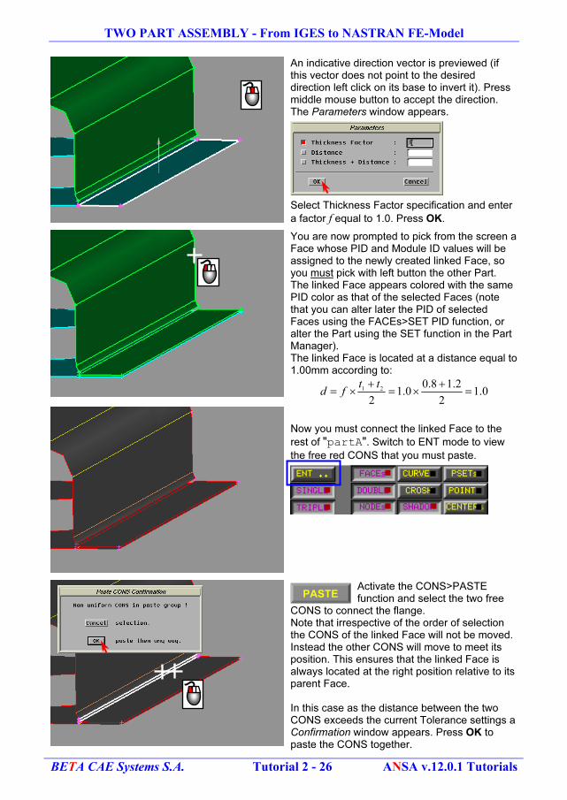
An indicative direction vector is previewed (if this vector does not point to the desired direction left click on its base to invert it). Press middle mouse button to accept the direction. The Parameters window appears.
Select Thickness Factor specification and enter
a factor f equal to 1.0. Press OK.
You are now prompted to pick from the screen a Face whose PID and Module ID values will be assigned to the newly created linked Face, so you must pick with left button the other Part. The linked Face appears colored with the same PID color as that of the selected Faces (note that you can alter later the PID of selected Faces using the FACEs>SET PID function, or alter the Part using the SET function in the Part Manager). The linked Face is located at a distance equal to 1.00mm according to:
0.12
2.18.00.1
2
21=
+×=
+×=
ttfd
Now you must connect the linked Face to the
rest of "partA". Switch to ENT mode to view
the free red CONS that you must paste.
Activate the CONS>PASTE function and select the two free
CONS to connect the flange. Note that irrespective of the order of selection the CONS of the linked Face will not be moved. Instead the other CONS will move to meet its position. This ensures that the linked Face is always located at the right position relative to its parent Face. In this case as the distance between the two CONS exceeds the current Tolerance settings a Confirmation window appears. Press OK to paste the CONS together.
PASTE

TWO PART ASSEMBLY - From IGES to NASTRAN FE-Model
BETA CAE Systems S.A. Tutorial 2 - 27 ANSA v.12.0.1 Tutorials
Note that the small fillet has been stretched to meet the linked flange. Create similar linked Faces in the other two flanges of the assembly and connect them. Be careful in the selection of red CONS so that the two parts are not pasted together.
Switch to PID mode and press the F10 key.
Note that the thickness factor specification method if at any later stage of the analysis the thickness of a part is altered in the respective PID card, the Faces are automatically relocated to a new position in order to satisfy the FACEs>OFFSET [LINK] Faces manipulation described in section 2.5 and the FACEs>LINK [CREATE].
The FLANGEs [LINK] function of the FOCUS group allows the identification of linked Faces. Activate the function
and only the linked Faces (parent and child) are left visible.
You can alter the link distance specification using the FACEs>LINK [EDIT] function. Activate the function
and select the Faces with the left mouse button. Confirm with middle mouse button. Change the thickness factor value to 1.1 and press OK.
EDIT
LINK
LINK
FLANGEs

TWO PART ASSEMBLY - From IGES to NASTRAN FE-Model
BETA CAE Systems S.A. Tutorial 2 - 28 ANSA v.12.0.1 Tutorials
The flanges are relocated and their distance is now:
1.12
2.18.01.1 =
+×=d
Use the MEASURE function to examine it.
Save the database from FILE>SAVE.
MEASURE
TWO PART ASSEMBLY - From IGES to NASTRAN FE-Model
BETA CAE Systems S.A. Tutorial 2 - 29 ANSA v.12.0.1 Tutorials
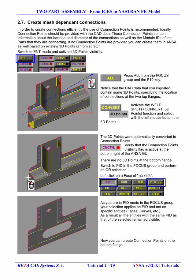
2.7. Create mesh dependant connections
In order to create connections efficiently the use of Connection Points is recommended. Ideally Connection Points should be provided with the CAD data. These Connection Points contain information about the location and diameter of the connections as well as the Module IDs of the Parts that they are connecting. If no Connection Points are provided you can create them in ANSA as well based on existing 3D Points or from scratch.
Switch to ENT mode and activate 3D Points visibility.
Press ALL from the FOCUS group and the F10 key.
Notice that the CAD data that you imported contain some 3D Points, specifying the location of connections at the two top flanges.
Activate the WELD SPOTs>CONVERT [3D Points] function and select with the left mouse button the
3D Points.
The 3D Points were automatically converted to Connection Points.
Verify that the Connection Points visibility flag is active at the
bottom right of the ANSA GUI.
There are no 3D Points at the bottom flange.
Switch to PID in the FOCUS group and perform an OR selection.
Left click on a Face of "partB".
As you are in PID mode in the FOCUS group your selection applies on PID and not on specific entities (Faces, Curves, etc.). As a result all the entities with the same PID as that of the selected remained visible. Now you can create Connection Points on the bottom flange.
ALL
3D Points
CONVERT
CNCTN.

TWO PART ASSEMBLY - From IGES to NASTRAN FE-Model
BETA CAE Systems S.A. Tutorial 2 - 30 ANSA v.12.0.1 Tutorials
Activate the WELD SPOTs>DEF.CNCT [AUTO] function. Select with the left mouse button the flange on
which you want to create Connection Points. Confirm with middle mouse button. The Definition Parameters window appears.
Select the distance definition mode and input a value of 30mm. Press OK. Nine new Connection Points were created according to the input settings.
Press ALL to bring both Parts back.
De-activate the shadow mode.
You can see all the Connection Points, 17 at the top two flanges and 9 at the bottom one.
Activate the WELD SPOTs>REALIZE function.
Select with the left mouse button all the Connection Points.
Selected Connection Points become highlighted. Pressing middle mouse button confirms the selections and opens the Connection Manager. (Note that when activating the REALIZE function, the Connections Selection Assistant window opens automatically. Ignore this window, as it is useful for more advanced and complicated applications).
AUTO
DEF.CNCT
ALL
REALIZE

TWO PART ASSEMBLY - From IGES to NASTRAN FE-Model
BETA CAE Systems S.A. Tutorial 2 - 31 ANSA v.12.0.1 Tutorials
The Connection Manager window hosts a lot of useful information such as:
-The number, Module ID and name of Parts involved in the selected Connection points -The number of selected Connection points -A list of each Connection Point with details about its diameter, the Module IDs of the Parts that it connects (four columns) and its Status and Error Class
- Functions to manage and realize the Connection points
- Functions to create connection elements for the selected Connection Points
As expected there are 26 Connection Points. Scroll in the list and observe that the first 17
Connection Points refer to "partA" with Module ID 100 and the remaining 9 refer to "partB" with
Module ID 200. This means that the information of the Connection Points is incomplete. Normally, for a connection between two parts, a Connection Point should have two Module IDs, one for each
connected Part. The 17 Connection Points contain information about "partA" (module ID 100)
only as they were created from 3Dpoints that initially belonged to that Part. On the other side the 9
Connection points contained information about "partB" (module ID 200) as they were defined on
a Face that belonged to that Part.
Press Edit. Five empty fields appear where you can input manually the connection diameter and up to four Module IDs to be assigned to the selected Connection points. You can perform this operation automatically, pressing the Auto button.
The Auto Edit Parameters window appears. Here you specify the search distance within which ANSA will search and identify Faces that belong to Parts close enough to be considered for connection. Press OK.
The information of the 26 Connection Points has been updated. Two Parts with the Module IDs 100 and 200 participate in each connection as presented in the list. Press the OK button at the bottom of the window to close the Connection Manager.
Now you can proceed with the realization of the connection elements. At this stage you will only connect the two top flanges. For the bottom one you will create mesh independent connections after meshing.

TWO PART ASSEMBLY - From IGES to NASTRAN FE-Model
BETA CAE Systems S.A. Tutorial 2 - 32 ANSA v.12.0.1 Tutorials
Activate the WELD SPOTs>REALIZE function.
Select with the left mouse button the Connection Points of the two top flanges, as shown. Confirm with middle mouse button.
The Connection Manager window appears. Seventeen Connection Points have been selected. Now will assign a diameter for these connections. Press the Edit button. The five empty fields appear. Enter a diameter of 3.0mm in the first field and press Finish.
The list is updated and the value 3.0 appears in all Connection Points. Now you must project the Connection Points on the Faces. Press the Project button.
The Projection Parameters window appears. Specify a maximum projection distance of 2 mm, activate the Project WELD SPOT on Perimeter, in order to align the mesh of the flanges. Press OK.
The projection is successful. All Connection Points are reported as Projected in the Status column.
Now you must select the type of connection element to be created. Select a CBAR from the FE Repr. list.
REALIZE

TWO PART ASSEMBLY - From IGES to NASTRAN FE-Model
BETA CAE Systems S.A. Tutorial 2 - 33 ANSA v.12.0.1 Tutorials
Notice how the bottom section of the Connection Manager changes, to accommodate the specification parameters of the CBAR elements.
The status of the Use Thickness to Diameter Map flag has no effect, as the diameter of the connections has been defined explicitly.
Activate the PA and PB flags 4 to disconnect the x-rotational degree of freedom at the ends of the CBAR elements.
Press Apply to create the CBAR elements.
Note that the keyword CBAR appears in the Error Class column for all selected Connection Points. Press OK at the bottom of the window to close the Connection Manager.
De-activate the CNCTN. Connection Points visibility and ensure that SPOTs and FE-Mod. visibility flags are active.
You can see the blue CBAR elements connected to the Faces through Connecting Spots, the yellow circles with a cross. If you zoom close you can also see the local coordinate system of the elements with the x-axis along the length of the element.
Press OK to close the PBAR card and the ESC key to close the Properties List window.
Open the Properties window. A new Property with ID 9 has been
created for the CBAR elements. Select it and press EDIT. The PBAR property card opens where the fields A, I1, I2 and J have been automatically filled for the corresponding diameter of 3 mm.
The mesh dependant connections have been created. Save the database from FILE>SAVE.
PR.LIST
TWO PART ASSEMBLY - From IGES to NASTRAN FE-Model
BETA CAE Systems S.A. Tutorial 2 - 34 ANSA v.12.0.1 Tutorials
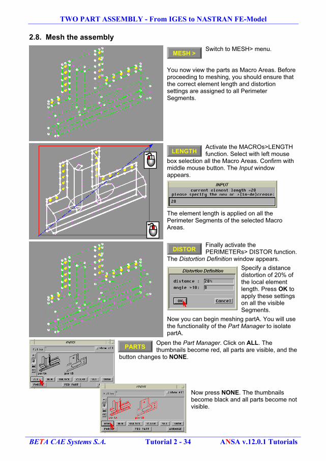
2.8. Mesh the assembly
Switch to MESH> menu.
You now view the parts as Macro Areas. Before proceeding to meshing, you should ensure that the correct element length and distortion settings are assigned to all Perimeter Segments.
Activate the MACROs>LENGTH function. Select with left mouse
box selection all the Macro Areas. Confirm with middle mouse button. The Input window appears.
The element length is applied on all the Perimeter Segments of the selected Macro Areas.
Finally activate the PERIMETERs> DISTOR function.
The Distortion Definition window appears.
Specify a distance distortion of 20% of the local element length. Press OK to apply these settings on all the visible Segments.
Now you can begin meshing partA. You will use the functionality of the Part Manager to isolate partA.
Open the Part Manager. Click on ALL. The thumbnails become red, all parts are visible, and the
button changes to NONE.
Now press NONE. The thumbnails become black and all parts become not visible.
MESH >
LENGTH
DISTOR
PARTS

TWO PART ASSEMBLY - From IGES to NASTRAN FE-Model
BETA CAE Systems S.A. Tutorial 2 - 35 ANSA v.12.0.1 Tutorials
Finally, left click on the thumbnail of
"partA". It
becomes red again and the part appears on the screen.
Press the LOCK flag to lock your selection.
Activate the SHELL MESH>SPOT-ME [Visible] function to mesh all visible Macro Areas with the Spot
Mesh algorithm. All Macro Areas are meshed as reported in the Text Window. The number of generated elements is displayed on the bottom left of the screen.
Activate Shadow mode and rotate the part to view it from
many angles.
Zoom out and view the other sides of the part.
The bottom flange has only one row of elements.
Switch to ENT selection mode in the FOCUS group and isolate with OR the flange.
Activate the PERIMETERs>NUMBER function
and select with the left mouse button the Perimeter Segment shown. The Input window appears where the current nodal number is displayed. Specify a new number of 1 and press Enter.
NUMBER
Visible
SPOT-ME
SHADOW

TWO PART ASSEMBLY - From IGES to NASTRAN FE-Model
BETA CAE Systems S.A. Tutorial 2 - 36 ANSA v.12.0.1 Tutorials
One Perimeter Node has been assigned to the Segment, and as a result the mesh of the Macro has been erased. Note that the Segment is now colored in red to show that its nodal number has been explicitly defined. While still in the NUMBER function select the other end of the flange with the right mouse button.
One Perimeter Node is assigned to that Segment, too.
Activate the SHELL MESH>REMESH [Select] function to mesh selected Macro Areas with the last
applied algorithm, in this case the Spot Mesh algorithm. Select with the left mouse button and confirm with the middle mouse button.
The Macro Area is meshed with two rows of quad elements.
Select
RE-MESH

TWO PART ASSEMBLY - From IGES to NASTRAN FE-Model
BETA CAE Systems S.A. Tutorial 2 - 37 ANSA v.12.0.1 Tutorials
Press ALL from the FOCUS group.
Note that only "partA" becomes visible as you
have previously Locked these entities. The number of visible shell elements is displayed on the left of the screen.
Press INVERT from the FOCUS
group. Now "partB" becomes
visible.
Note that the linked flanges are already meshed with the same mesh. You only need to mesh the remaining. You can help in the generation of a good quality mesh by placing some Hot Points at specific location to align and orient the mesh.
Prepare the internal perimeters for meshing. Activate the HOT
POINTS>DELETE function and select with the left mouse button the Hot Points shown.
Now assign a new nodal number on the internal perimeter of the
top hole. Activate PERIMETERs>NUMBER function and select the Segment.
Current nodal number is five. Input a value of 3, so that the hole becomes square shaped and fits with the quad mesh better. Press Enter.
ALL
INVERT
DELETE
NUMBER

TWO PART ASSEMBLY - From IGES to NASTRAN FE-Model
BETA CAE Systems S.A. Tutorial 2 - 38 ANSA v.12.0.1 Tutorials
The hole is now square but it is still not aligned with the mesh of the nearby flanges.
Use the PERIMETERs>SLIDE function. Select with left mouse
button the Hot Point.
Slide the Hot Point along the perimeter by moving the mouse cursor. Left click again to fix the Hot Point to its new position.
Activate the same function again and select the single Hot Point of the other internal perimeter. Slide it and lock it at a new position exactly on top of a Perimeter Node of the bottom flange.
Activate the HOT POINTs>PROJECT function and
select a Hot Point from the nearby Perimeter Segments. The Hot Point becomes highlighted. Left click on the Perimeter Segment of the hole. The selected Hot Point is projected on the Segment a new Hot point is created at that location.
SLIDE
PROJECT

TWO PART ASSEMBLY - From IGES to NASTRAN FE-Model
BETA CAE Systems S.A. Tutorial 2 - 39 ANSA v.12.0.1 Tutorials
Use the same function to project two more Hot Points on the perimeter of the hole as shown.
Now the Macro is ready for meshing.
Activate the SHELL MESH> SPOT MESH [Visible] function. Note that this option does not affect already
meshed Macro Areas.
The mesh is generated. The number of visible elements is reported on the left side of the screen.
De-activate the LOCK flag from the FOCUS group and press ALL to make all the entities visible.
Save the database from FILE>SAVE.
Visible
SPOT-ME

TWO PART ASSEMBLY - From IGES to NASTRAN FE-Model
BETA CAE Systems S.A. Tutorial 2 - 40 ANSA v.12.0.1 Tutorials
2.9. Examine the quality of the mesh
In this stage you will examine the mesh for defects and shell element quality. First check involves the identification of Macro Areas that were not meshed.
Activate the UNMESHED function from the FOCUS group.
Only the FE-model entities, the connection elements, remain visible, indicating that there are no unmeshed Macros.
Press ALL to bring all entities back.
Activate the BOUNDS view mode. De-activate temporarily PERIM, HOT PNT and WIRE flags.
In this mode only the free edges of visible shell elements are displayed in red. You can thus identify if there are openings. In this case red lines are located only at the boundaries of the parts and at their internal perimeters, indicating that the mesh is OK.
Activate the Presentation Parameters window by pressing the F11 key. In this window you specify the
calculation method and threshold values for various quality criteria. Keep the default settings and activate the flags for the criteria Aspect, Skewness and Warping. Press OK at the bottom of the window to accept the settings and close. De-activate the Middle Point Dev and Align. flags at the bottom.
To perform the quality check switch to HIDDEN view mode by activating the respective flag (activate back PERIM and HOT PNT).
Elements that violate the specified quality criteria are colored according to the legend on the right. The number of visible violating elements is shown on the left, under OFF.
UNMESHED
ALL
F11

TWO PART ASSEMBLY - From IGES to NASTRAN FE-Model
BETA CAE Systems S.A. Tutorial 2 - 41 ANSA v.12.0.1 Tutorials
To locate these elements (if they can not be easily identified) press
the EXTREME function of the FOCUS group.
Only the Macro Areas that contain elements that are violating quality criteria remain visible. In this case there are two elements suffering from Warping.
Note that the FE-model CBAR elements also remain visible. To remove them from the view
de-activate the FE-Model flag button.
Isolate one Macro Area with an OR selection in ENT mode.
Zoom in closer.
Press NEIGHB from the FOCUS group to bring neighboring Macro Areas to view, in order to better understand the local shape of the mesh.
Rotate the part to see in which directions the element is warped so as to fix it (the normal vectors showing the warping angle are displayed here in blue for visualization purposes).
EXTREME

TWO PART ASSEMBLY - From IGES to NASTRAN FE-Model
BETA CAE Systems S.A. Tutorial 2 - 42 ANSA v.12.0.1 Tutorials
Activate the GRIDs> MV SURF [SINGLE] function to move a Perimeter Node along the Perimeter Segment, thus
reducing the warp of the element. Select with the left mouse button the node to be moved. Start moving the node. The motion takes place along the Perimeter Segment, thus on the underlying CAD surface. During the motion the participating elements are highlighted and their quality is continuously monitored and colored accordingly. As soon as the blue color disappears the element is fixed.
Press the left mouse button to lock the node at its new position.
Press ALL to bring all the Macro Areas back and the EXTREME again to keep only the Macro with the other warped quad element.
Perform the same quality improvement to the other element.
Having corrected the two elements, press ALL again to bring all the parts back.
While still in HIDDEN mode, the legend does not display any OFF elements. This implies that the mesh is OK.
The final check of the mesh consists of penetration check. Activate the ELEMENTs>PENETR. [Initial Penetration] function to check for interpenetrating shell elements. Press OK in the Warning window that appears to proceed with the check. At the
end of the check the message “No penetration found” appears in the Text Window. Proceed with the check for thickness penetration.
Activate the ELEMENTs>PENETR. [Property thickness] function to check for thickness penetration.
The Input window appears. Input a factor of 1 and press enter. The check is performed and the message “No penetration found” appears again. This
is expected as all the flanges are linked with a thickness factor of 1.1.
Save the database from FILE>SAVE.
SINGLE
MV SURF
INITIAL PENETRATION
PENETR.
PROPERTY THICKNESS
PENETR.
TWO PART ASSEMBLY - From IGES to NASTRAN FE-Model
BETA CAE Systems S.A. Tutorial 2 - 43 ANSA v.12.0.1 Tutorials
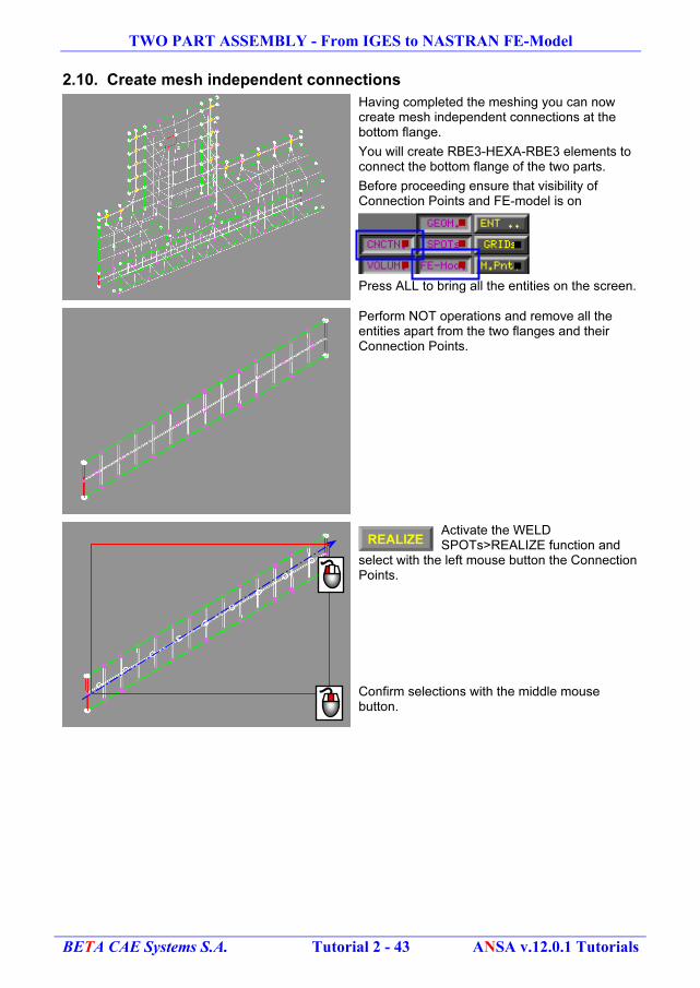
2.10. Create mesh independent connections
Having completed the meshing you can now create mesh independent connections at the bottom flange.
You will create RBE3-HEXA-RBE3 elements to connect the bottom flange of the two parts.
Before proceeding ensure that visibility of Connection Points and FE-model is on
Press ALL to bring all the entities on the screen.
Perform NOT operations and remove all the entities apart from the two flanges and their Connection Points.
Activate the WELD SPOTs>REALIZE function and
select with the left mouse button the Connection Points.
Confirm selections with the middle mouse button.
REALIZE

TWO PART ASSEMBLY - From IGES to NASTRAN FE-Model
BETA CAE Systems S.A. Tutorial 2 - 44 ANSA v.12.0.1 Tutorials
The Connection Manager appears. Nine Connection Points have been selected,
connecting "partA" with "partB".
Now you can assign a diameter value for the selected Connection Points.
Press the Edit button.
The five fields appear. Enter a value of 5.0 mm in the first filed and press Finish.
The fields close and the list is updated with the diameter value in the first column for all the Connection Points.
Then select the RBE3-HEXA-RBE3 option from the FE Repr. pop up menu.
Then bottom section of the Connection Manager changes to accommodate the option for this type of elements.
Press the Apply button to create the connections.
The elements are generated successfully as reported in the two last columns of the Connection Manager.
Press OK to exit.

TWO PART ASSEMBLY - From IGES to NASTRAN FE-Model
BETA CAE Systems S.A. Tutorial 2 - 45 ANSA v.12.0.1 Tutorials
The RBE3-HEXA-RBE3 elements are visible. Note the yellow Connecting Spots that connect the Shell Geometry Mesh with the FE-Model entities, the RBE3 elements.
To view clearer the connecting elements switch to PID and SHADOW view mode and remove from the view (NOT operation) one of the two flanges.
Open the Properties window. A new Property with ID 8 has been
created for the CHEXA elements. You can select it and press EDIT to modify the contents of the PSOLID card.
Press ALL to make all the entities visible.
You can de-activate the visibility of Perimeter Segments and Hot Points in order to view the model without them.
The legend reports the number of the visible shell and solid elements
Save the database from FILE>SAVE.
PR.LIST
ALL

TWO PART ASSEMBLY - From IGES to NASTRAN FE-Model
BETA CAE Systems S.A. Tutorial 2 - 46 ANSA v.12.0.1 Tutorials
2.11. Define loads and constraints
Having completed the mesh model and the connections you can proceed with the application of loads and constraints. Switch to DECK> menu and select NASTRAN.
(For clarity we have switched to SHADOW and ENT display mode and activated PERIM and HOTPNT flags.)
You will create one Set of SPC1 and two different Load Sets. One Load Set will consist of axial tensile FORCES on the top member and the other will be shear FORCES. The two Sets of FORCES will be solved as two different Subcases in NASTRAN. The SPC1 Set, will be common in both Subcases.
Press the F12 key to open the Deck Parameters window. You can control the visibility of specific FE-model by activating the relative flag.
As you will create SPC1 and FORCE entities, activate the relative flags (which are not active by default), so that you can see them when defining them.
Press the Apply button to confirm and exit.
Now you can begin the actual application of the constraints on your model.
Rotate your model to a view that allows easy selection of nodes.
Activate the SPCs>SPC1 [Node] function and select with left mouse button the nodes that you want to apply
SPC1s on.
F12
Node
SPC1

TWO PART ASSEMBLY - From IGES to NASTRAN FE-Model
BETA CAE Systems S.A. Tutorial 2 - 47 ANSA v.12.0.1 Tutorials
The selected nodes are highlighted. You can remove nodes from the selection with the right mouse button if required. Press middle mouse button to confirm.
The SPC1 entity card appears. Type 123 in the C field to restrict the three translational DoFs. Note that the SID field (Set ID) has the value 1 by default, which means that the SPC1s will be put to the SPC Set 1.
Press OK to accept.
The created SPC1s appear in blue color in ENT mode, with three branches indicating the restriction in the three degrees of freedom.
If you are in PID view mode they will appear colored according to the Set that they belong to.
Note that yellow Connecting Spots have been defined at the nodes where Geometry shell mesh is connected to FE-model entities (SPC1s in this case).
Move on the other end of the part, and activate again the SPCs>SPC1 [Node] function. Select the nodes and press
middle mouse button.
Again the SPC1 card opens. Input 23 in the C field, to constrain the translational DoFs in the global y and z-axes. Again the SID field has the value 1. These SPC1s will also be put to the same SPC Set 1.
Press OK to confirm and close the card.
The SPC1 entities appear in blue color with two branches in the Y and Z global coordinate system directions.
Node
SPC1

TWO PART ASSEMBLY - From IGES to NASTRAN FE-Model
BETA CAE Systems S.A. Tutorial 2 - 48 ANSA v.12.0.1 Tutorials
Activate the B.C. SETs>SPC function. The SPC Sets List
window appears. There is one "Anonymous
SPC Set" with ID=1 which was generated
automatically by ANSA during the SPC1s creation. Select it with the left mouse button and
it becomes marked in black. Press the EDIT button. The SPC
Set card opens.
Change the name to "Constraints Set",
keep the SID=1 and press OK.
The list is updated, and the "Constraints
Set" with ID=1 appears.
Press the ESC key to exit from the SPC Sets List window.
You have created the SPC1s and the SPC Set. Proceed with the definition of the Loads and their Sets.
Move to the top end of the part to apply FORCES.
Activate the LOADs>FORCES [Node] function and select with left mouse button the nodes on
which you want to apply the loads to.
SPC
Esc
Node
FORCES

TWO PART ASSEMBLY - From IGES to NASTRAN FE-Model
BETA CAE Systems S.A. Tutorial 2 - 49 ANSA v.12.0.1 Tutorials
The selected nodes are highlighted. Confirm with middle mouse button. The Force-Moment card opens. Input 50 in the F field and 1 in the N3 (indicating the direction vector in the global positive Z-axis). Keep the default value of 1 in the SID field.
Press OK in the Force-Moment card to confirm and exit.
The Force vectors are displayed in yellow color in ENT mode. If you are in PID view mode they will appear colored according to the Set that they belong to.
Activate the LOADs>FORCES [Node] function again, select the same nodes and confirm with middle mouse button. A new Force-Moment card opens. Input 25 in the F field, and 1 in the N1 field, indicating the direction in the positive global X-axis. Type in the value 2 in the SID field so that these Forces are put in a different Load Set.
Press OK to confirm and close the Force-Moment card. New Force entities are created and displayed.

TWO PART ASSEMBLY - From IGES to NASTRAN FE-Model
BETA CAE Systems S.A. Tutorial 2 - 50 ANSA v.12.0.1 Tutorials
Press the F11 key to open the Presentation Parameters window. At the bottom of this window activate the LABELS: Loads flag.
Press the OK button to confirm and exit.
Now the magnitude of the Forces is displayed on the screen.
Activate the B.C. SETs>LOAD function. The Load Sets List
window appears. There are two "Anonymous
Load Set" with IDs 1 and 2 that were
generated automatically by ANSA during the FORCEs creation. Select them with the left mouse button and they become marked in black. Press the EDIT button.
The first Load Set card with SID=1 opens.
Change the name to "Axial Load" and
press OK.
The second Load Set card with SID=2 opens.
Change the name to "Shear Load" and
press OK.
The Load Sets List window now contains the two Load Sets that you have defined.
Press the ESC key to exit from the Load Sets List window.
All SPC and Loads have been applied.
LOAD
Esc
F11

TWO PART ASSEMBLY - From IGES to NASTRAN FE-Model
BETA CAE Systems S.A. Tutorial 2 - 51 ANSA v.12.0.1 Tutorials
Press F10 to zoom all in the standard isometric view.
Note that if you switch to PID display mode the SPC1s and the FORCEs are colored according to the Set that they belong to.
Save the database from FILE>SAVE.
F10
TWO PART ASSEMBLY - From IGES to NASTRAN FE-Model
BETA CAE Systems S.A. Tutorial 2 - 52 ANSA v.12.0.1 Tutorials
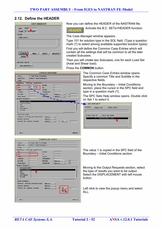
2.12. Define the HEADER
Now you can define the HEADER of the NASTRAN file.
Activate the B.C. SETs>HEADER function.
The Case Manager window appears.
Type 101 for solution type in the SOL field. (Type a question mark (?) to select among available supported solution types)
First you will define the Common Case Entries which will contain all the settings that will be common to all the later created Subcases.
Then you will create two Subcases, one for each Load Set (Axial and Shear load).
Press the COMMON button.
The Common Case Entries window opens. Specify a common Title and Subtitle in the respective fields.
Moving to the Boundary – Initial Conditions section, place the cursor in the SPC field and type in a question mark (?).
The SPC Sets Help window opens. Double click on Set 1 to select it.
The value 1 is copied in the SPC field of the Boundary – Initial Conditions section. Moving to the Output Requests section, select the type of results you want to be output. Select the DISPLACEMENT with left mouse button. Left click to view the popup menu and select ALL.
HEADER
?

TWO PART ASSEMBLY - From IGES to NASTRAN FE-Model
BETA CAE Systems S.A. Tutorial 2 - 53 ANSA v.12.0.1 Tutorials
(note DISPLACEMENT=ALL has been updated).
Next select FORCE. Again select ALL.
Scroll down in the list and perform the same for SPCFORCES, STRAIN and STRESS. (Note that =ALL appears to all the types of results that you have selected) Finally press OK to confirm and exit the Common Case Entries card.
Back to the Case Manager window, press NEW to create the first Subcase, which will contain the axial loading Force Set.

TWO PART ASSEMBLY - From IGES to NASTRAN FE-Model
BETA CAE Systems S.A. Tutorial 2 - 54 ANSA v.12.0.1 Tutorials
A new Subcase window opens.
Enter the Subcase number and title in the respective fields.
Moving to the Boundary – Initial Conditions section, place the cursor in the LOAD field and type in a question mark.
The Load Sets Help window opens. Double click on Set 1 to select it. You do not have to specify anything in the Output Requests sections as this was performed in the Common Case Entries card. Press OK to confirm and exit the Subcase window.
Note that Subcase 1 is displayed in the list. Press NEW again to create a second Subcase.
A new Subcase window opens.
Enter the Subcase number and title in the respective fields. Moving to the Boundary – Initial Conditions section, place the cursor in the LOAD field and type in a question mark.
The Load Sets Help window opens. Double click on Set 2 to select it. You do not have to specify anything in the Output Requests sections as this was performed in the Common Case Entries card. Press OK to confirm and exit the Subcase window.
?
?

TWO PART ASSEMBLY - From IGES to NASTRAN FE-Model
BETA CAE Systems S.A. Tutorial 2 - 55 ANSA v.12.0.1 Tutorials
Back to the Case Manager window, the two Subcases are listed. Press the Parameters button
The Parameters window opens. Scroll down in the list and click on PARAM, POST. Then select the value –1 from the popup menu. Press UPDATE to assign the selected flag to the parameter.
Press the ESC key to exit from the Parameters window.
Returning to the Case Manager window, select with the left mouse button the two Subcases. They become marked in black. (Note that only selected Subcases will be output in the NASTRAN file.)
Press the ESC key to exit the Case Manager window.
Save the database from FILE>SAVE.
Esc
Esc

TWO PART ASSEMBLY - From IGES to NASTRAN FE-Model
BETA CAE Systems S.A. Tutorial 2 - 56 ANSA v.12.0.1 Tutorials
2.13. Output the NASTRAN FE-model
The last step in this tutorial consists of outputting the NASTRAN file.
Select FILE>OUTPUT>NASTRAN.
The File Manager window opens where you can navigate and type the filename of the NASTRAN output file
Type in the name assembly.nas and
press OK.
The Output Parameters window appears. Select ALL from the popup menu, so that all entries in the database are output. Press OK to proceed with the output process.
The NASTRAN Deck Parameters window appears, providing you with a preview of the HEADER. (Here you can modify the HEADER if you want). Press OK to accept the HEADER file and complete the NASTRAN output. Save the database from FILE>SAVE, and close ANSA from FILE>QUIT.

TWO PART ASSEMBLY - From IGES to NASTRAN FE-Model
BETA CAE Systems S.A. Tutorial 2 - 57 ANSA v.12.0.1 Tutorials
2.14. Conclusion
In this tutorial you have followed all the basic steps to create a FE-model for NASTRAN. Not all capabilities were demonstrated. Refer also to ANSA v12.x User’s Guide and to the On-Line Help for the functionality of ANSA and detailed description of functions and procedures.

TWO PART ASSEMBLY - From IGES to NASTRAN FE-Model
BETA CAE Systems S.A. Tutorial 2 - 58 ANSA v.12.0.1 Tutorials