type cvx and cvx-1 synchro-verifier relays for class 1e ... · i.l. 41-682.11 type cvx and cvx-1...
TRANSCRIPT


I.L. 41-682.11 Type CVX and CVX-1 Synchro-Verifier Relays
2
Figure 1. CVX-1 Relay Front View, Out of Case
POTENTIOMETER (R3)CIRCLE ADJUST
RESTRAINTELECTROMAGNET
TIME DIAL
Figure 2. CVX-1 Relay Rear View, Out of Case.
OPERATINGELECTROMAGNET
TELEPHONERELAY (T2)
ADJUSTABLERESISTOR (R4)BALANCE ADJUST
TELEPHONERELAY (T1)
VOLTAGE SENSINGTELEPHONE RELAYS(V1 & V2)

41-682.11
3
to avoid the possibility of pumping when closing intoa fault.
2.0 CONSTRUCTION AND OPERATION
The type CVX relay consists of an operating element(rear) and a restraining element (front) mounted on acommon disc, a circle adjust potentiometer (R3), anda balance adjust resistor (R4). The relay also hastelephone relays (T1 & T2) in the time delay circuit tooverride any possible contact chatter during a seis-mic event. See Figures 1 and 2.
The CVX-1 Relay in addition to the componentsnoted above, has two telephone type ac voltagesensing relays (V1 & V2). See Figures 1 and 2.
2.1 OPERATING ELEMENT
The operating unit consists of an “E” type laminatedelectromagnet with two main coils on the center leg,a lag coil on the left leg, and a lag coil on the rightleg. A resistor is connected across the shading coil.
When the relay is energized with two voltages, a fluxis produced that is proportional to the sum of theapplied voltages. This flux divides and returnsthrough the outer legs of the electromagnet. The lagcoil on the left leg causes the flux in that leg to lag themain pole flux. The out of phase fluxes thus pro-duced in the disc gap causes a contact closingtorque. The resistor connected across the lag coil ofthe electromagnet provides adjustment for differentoperating circles of the relay.
2.2 RESTRAINING ELEMENT
The restraining element consists of an “E” type lami-nated electromagnet with two main coils on its centerleg and a lag coil on its left leg. A flux proportional tothe difference of the applied voltages to the relay isproduced. This flux divides and returns through theouter legs of the electromagnet. The lag coil causesthe flux through the leg to lag the main pole flux. Theout-of-phase fluxes thus produced in the disc gapcauses a contact opening torque.
2.3 TIME DELAY CIRCUIT
The time delay circuit consists of two dc telephonetype relays. This intentional time delay circuit appliesto the CVX(-1) contact opening only, and is designed
to override any possible contact chatter during aseismic event.
2.4 AC TELEPHONE RELAYS (V1 & V2), CVX-1 ONLY
The telephone operating relay units are fast operat-ing types energized by the application of an ac volt-age. In these relays, an electromagnet energized byac voltage, attracts a right angle armature whichoperates a set of contacts.
2.5 CVX OPERATION WITH EXTERNAL VOLT-AGE RELAYS
The connections shown in Figure 6 using externaltype SG voltages relays will provide the followingoperation:
1. Close the breaker when the bus is live and theline is dead, through the 59B make contact and27L break contact
2. Close the breaker when the line is live and thebus is dead, through the 59L make contact and27B break contact.
3. Close the breaker when the line and bus areboth live and when their respective voltages areapproximately normal, equal in phase, and ofthe same frequency, through the CVX contact.
It is recommended that the number of reclosures belimited by using either a single or a multi-shot reclos-ing relay in conjunction with the CVX and SG relays.
2.6 CVX-1 OPERATION
In the CVX-1, the internal V1 and V2 perform thefunctions of external 59B and 27L relays respectively.
The connections shown in Figure 7 using the typeCVX-1 relay will provide the following operation:
1. Close the breaker when the bus is live and theline is dead, through the V1 make contact andV2 break contact.
2. Close the breaker when the line is alive and thebus is dead, through the V2 make contact andV1 break contact.
3. Close the breaker when the line and bus areboth live and their respective voltages are

I.L. 41-682.11 Type CVX and CVX-1 Synchro-Verifier Relays
4
approximately normal, equal, in phase, and ofthe same frequency through the CVX -1 contact.
It is recommended that the number of reclosures belimited by using either a single or a multi-shot reclos-ing relay in conjunction with the CVX1 relay.
3.0 CHARACTERISTICS
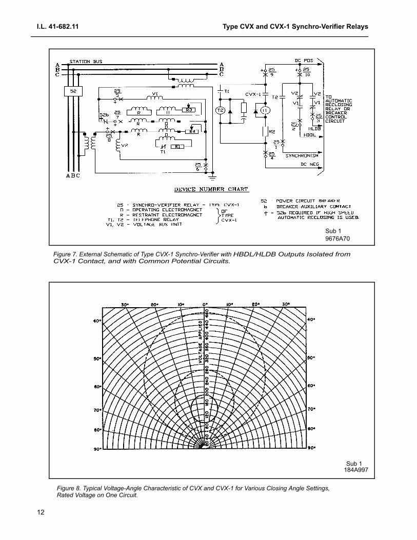
The type CVX and CVX-1 relays can be adjusted foroperating circles from 40° to 60° as shown in Figure8. The relay is typically calibrated for the 40° circle asshipped from the factory. These circles apply whenone side has rated voltage. The relay operates if theother voltages falls within the appropriate circle.
The operating time of the relay is shown in Figure 9.These time curves are obtained from the #11 timedial setting when the applied voltages are equal torated voltage, in phase and of the same frequency.Shorter operating times can be obtained at differenttime dial settings as shown in Figure 10.
Figure 11 shows the maximum slip frequency forwhich operation of the CVX element can occur. Themaximum slip frequency is a function of the circleand time dial settings. This characteristic is of inter-est in estimating the worst case angular difference atthe instant of breaker closure, for cases where thetwo systems are slipping slowly.
Figure 12 shows typical CVX reset times for 20°, 40°and 60° circle settings. Note: Class 1E Relaysshould be set at 40° or higher.
3.1 BURDEN
The burden imposed on each potential source by theCVX relay, with rated voltage applied to both circuitsof the relay is as follows:
The burden of the CVX relay with rated voltage
applied to one circuit is as follows:
For the CVX-1 relay, additional burden of each tele-phone relay at 120 Volts is as follows:
Volt Amperes ................................................ 10.62Power Factor ..................................................... 0.64
4.0 RELAY SETTINGS
As shipped from the factory the relays are calibratedfor a 40 degree circle. Other operating circles from40° to 60° can be obtained by adjusting the left handpotentiometer (front view) in the relay. The procedureis described under Circles Other than 40 Degrees, inSection 7.7.
Set the time dial so that the relay will not operatewhen the systems are swinging too fast. The #11time dial is recommended when the 60° circle settingis used. A setting of #4 time dial or higher is recom-mended with the 40° circle. If a longer delay isdesired, a higher time dial setting may be used.
To evaluate the effect of time dial and circle settingson the worst-case phase-angle difference betweenthe two systems at the instant of breaker closure,refer to Figure 9. For example, assume a 40° circleand #4 time dial setting. Also assume that the sys-tems are slipping at a frequency of 0.048 hertz, Fig-ure 11 shows the maximum slip for which the relaywill operate. This means that the relay contactsclosed just as the one voltage vector moves out ofthe circle.
This would mean that the system would be 40°out-of-phase at the instant that the breaker close cir-cuit is energized. The phase angle at the instant ofbreaker closure is:
φ = 40° + 0.048 x 360TB = 40° + 17.3TB
where TB = breaker closing time in seconds.
60 Hertz 50 Hertz
Volt Amperes 15.4 23.3
Power factor 0.422 0.309
Watts 6.5 7.2
60 Hertz 50 Hertz
Volt Amperes 15.4 23.3
Power factor 0.422 0.309
Watts 6.5 7.2

41-682.11
5
Let TB = 0.5 Seconds
Then 40° + 17.3 x 0.5 = 48.6°
5.0 INSTALLATION
The relays should be mounted on switchboard pan-els or their equivalent in a location free from dirt,moisture, excessive vibration, and heat. Mount therelay vertically by means of the four mounting holeson the flanges for the semi-flush type FT case. Themounting screws may be utilized for grounding therelay. External toothed washers are provided for usein the locations shown on the outline and drilling planto facilitate making a good electrical connectionbetween the relay case, its mounting screws and therelay panel. Ground Wires should be affixed to themounting screws as required for poorly grounded orinsulating panels. Other electrical connections maybe made directly to the terminals by means of screwsfor steel panel mounting.
For detail information on the FT case refer to Instruc-tion leaflet 41-076 for semi-flush mounting.
6.0 ADJUSTMENTS AND MAINTE-NANCE
NOTE: The proper adjustments to insure correctoperation of this relay have been made at the fac-tory. Upon receipt of the relay, no customeradjustments, other than those covered under“Settings” should be required.
6.1 ACCEPTANCE CHECK
The following check is recommended to insure thatthe relay is in proper working order:
6.1.1 Disk Unit Contacts (Time Dial)
The index mark on the movement frame will coincidewith the “0” mark on the time dial when the stationarycontact has been moved through approximatelyone-half of its normal deflection. Therefore, with thestationary contact resting against the backstop, theindex mark is offset to the right of the “0” mark byapproximately 0.020". The placement of the varioustime dial positions in line with the index mark will giveoperating times as shown on the time curve.
6.1.2 Operating Circle
Connect the CVX relay per the test diagram, Figure15. CVX-1 relays should be connected in a similarmanner to correspond with the wiring of the particularstyle CVX-1 using Figure 16. The contacts shouldjust close under the following condition:
When V1 and V2 are equal to rated voltage and theirphase difference is between 38° and 42° (either lead-ing or lagging), verify that the contacts should justopen within the make angle plus approximately 4°.
6.1.3 Time Curve
With the time dial set at position 11, the contactshould close in 6 ±1 seconds when V1 and V2, equalto rated voltage at zero phase angle, are applied.
6.1.4 Time Delay Circuit (T1, T2)
With test connections made according to Figures 15and 16, open the D.P.S.T. swtich. The timer startshould be set on contacts (make) and the timer stopshould be on volts (fall). The drop out time of T1 &T2 should be between 300 to 450 msec.
6.1.5 Telephone Relays (V1 & V2), CVX-1 Only
Apply ac voltage to each telephone relay circuit. Thetelephone relay should pickup when 95 volts ac isapplied.
6.2 ROUTINE MAINTENANCE
All relays should be inspected periodically and thetime of operation should be checked at least onceevery two years or at such other time intervals asmay be dictated by experience to be suitable to theparticular application.
All contacts should be periodically cleaned. A contactburnisher Style #182A836H01 is recommended forthis purpose. The use of abrasive materials for clean-ing contacts is not recommended, because of thedanger of embedding small particles in the face ofthe soft silver contact and thus impairing the contact.
7.0 CALIBRATION
Use the following procedure for calibrating the relay ifthe relay has been taken apart, received repairs, or

I.L. 41-682.11 Type CVX and CVX-1 Synchro-Verifier Relays
6
the adjustments have been disturbed. This proce-dure should not be used until it is apparent that therelay is not in the proper working order (See Accep-tance Check).
7.1 CONTACTS
For Disc Unit Contacts see section 6.1.1
7.2 PRELIMINARY ADJUSTMENTS
Remove the permanent magnet from the relay andset the time dial on the #11 position. Next unwind thespring for zero tension on the #11 position. This canbest be noticed by unwinding the spring until the con-tact will not move when the time dial is moved a smalldistance beyond the #11 position.
The spring convolutions may touch during this opera-tion and the outer convolutions may hit other sur-faces of the relay. This interference should bedisregarded because its effect on the final calibrationwill be negligible. The reason for unwinding thespring is that the amount of tension on the resetspring affects the diameter of the circle. Hence thespring tension has to be removed initially so that onlythe left hand potentiometer (R3) will affect the oper-ating circle.
7.3 SPURIOUS TORQUE ADJUSTMENTS
a) With the relay set as per the preliminary adjust-ments, open both lag coil circuits of the rear elec-tromagnet This can be done by opening thescrew connection on both the lag coils of the rearelectromagnet.
b) Connect the relay to test circuit of Figure 15 forCVX, or Figure 16 for CVX-1, and then applyrated voltage at zero phase angle on both cir-cuits. All voltage settings are to be within 1/4Volts.
7.4 CENTERING CIRCLE
a) De-energize the relay and close the left lag coilcircuit front view of the rear electromagnet andset the left hand potentiometer (R3) at approxi-mately one-third of its resistance.
b) Adjust the phase shifter on the lagging directionuntil the contacts just close with V1 and V2 equalto rated voltage. Note the angle at which the con-tacts just close.
c) Adjust the phase shifter in the leading directionuntil the contacts just close with V1 and V2 equalto rated voltage. If the latter angle is not within ±1degree of the former angle, adjust R4, the topright hand resistor (rear view) until the twoangles are within ±1 degree of each other.
7.5 SPRING ADJUSTMENT
a) Adjust R3, the left potentiometer (front view)such that the moving contact just leaves andreturns to the backstop of the time dial at the #11position between 30° and 31° for CVX andbetween 35° and 36° for CVX-1 with rated volt-age on both sides (leading or lagging: increasingthe resistor decreases the angle).
b) Change the angle to 40° and adjust the resetspring until the contacts just make.
c) Rotate the phase shifter to move V2 through zerophase angle where the contacts just make. Thecontacts should just close at an angle of 40° ± 2°with V1 and V2 equal to rated voltage.
d) With V1 equal to rated voltage, the contactsshould just close when V2 is increased to 60V±2.5V in phase with V1. If necessary, readjustspring slightly to obtain this condition. The relayis now calibrated for a 40° circle. Spring convolu-tions must not touch after this adjustment.
e) Reconnect the right lag coil of the rear electro-magnet and adjust R3, the left hand potentiome-ter (front view) to achieve the 40° degree circle(where the contacts just close at an angle of 40°± 2°).
7.6 TIME CURVE
Install the permanent magnet on the relay. Adjust thepermanent magnet keeper until the operating time ofthe relay from the #11 time dial position is ±6 sec-onds with V1 and V2 equal to rated voltage at zerophase angle.
7.7 CIRCLES OTHER THAN 40 DEGREES
This adjustment should not be done until the aboveadjustments for a 40° circle has been completed.
If another circle other than 40° is desired, adjust R3,the left hand potentiometer (front view) to obtain thedesired circle. For example, if a 50 degree circle is
41-682.11
7
desired, adjust R3 until the contacts just close withV1 and V2 equal to rated voltage at 50° phase angle.It may be necessary to readjust R4, the right handresistor (rear view) to position the desired circle sym-metrically about the zero degree line. See “CenteringCircle” (section 6.4) for procedure. The time for the
operation will be as shown in the time curves of Fig-ure 10.
8.0 RENEWAL PARTS
Repair work can be done most satisfactorily at thefactory. However, interchangeable parts can be fur-nished to the customers who are equipped for doingrepair work. When ordering parts, always give thecomplete nameplate data.
I.L. 41-682.11 Type CVX and CVX-1 Synchro-Verifier Relays
8
LIST OF FIGURES
Figure 1 CVX-1 Relay Front View, Out of Case ...............................................................................Pg.2
Figure 2 CVX-1 Relay Rear View, Out of Case ................................................................................Pg.2
Figure 3 Internal Schematic Type CVX Synchro-Verifier Relay with Isolated PotentialCircuits, in Type FT-21Case - 9676A63 ............................................................................Pg.9
Figure 4 Internal Schematic Type CVX-1 Synchro-Verifier with HBDL/HLDB Outputs Isolated from CVX-1 Contact. Common Potential Circuits, in Type FT-21Case - 9676A30 ..............................................................................................................Pg.10
Figure 5 External Schematic of Type CVX Synchro-Verifier Relay,in type FT-21 Case - 9676A69 ........................................................................................Pg.11
Figure 6 External Schematic of Type CVX Synchro-Verifier Relay,in type FT-21 Case, with External Voltage Relays - 9676A78 .........................................Pg.11
Figure 7 External Schematic of the Type CVX-1 Synchro-Verifier Relay,in Type FT-21 Case - 9676A70 .......................................................................................Pg.12
Figure 8 Curve, Typical Voltage Angle characteristics - 184A997 .................................................Pg.12
Figure 9 Curve, Typical Time Phase Angle Curves - 184A998 .....................................................Pg.13
Figure 10 Curve, Operating Time Variations - 184A999 .................................................................Pg.14
Figure 11 Curve, Maximim Slip Frequency Cuves - 185A123 .........................................................Pg.15
Figure 12 Curve, Typical Reset TImes - 619595 .............................................................................Pg.16
Figure 13 Curve, V1 Voltage for Different Operating Circles - 471191 .............................................Pg.17
Figure 14 Curve, Operating Times from #11 Time Dial Setting - 471192 .......................................Pg.17
Figure 15 Test Diagram for CVX Relay - 1507B43 ..........................................................................Pg.18
Figure 16 Test Diagram Type CVX-1 Relay - 1507B44 ...................................................................Pg.19
Figure 17 Outline and Drilling Plan for FT-21 Case - 3519A66 ......................................................Pg.20

41-682.11
9
Sub 1 9676A63
Figure 3. Internal Schematic CVX Synchro-Verifier Relay with Isolated Potential Circuits.

I.L. 41-682.11 Type CVX and CVX-1 Synchro-Verifier Relays
10
Sub 19676A30
Figure 4. Internal Schematic Type CVX-1 Synchro-Verifier Relay in Type FT-21 Case with HBDL/HLDB Outputs Isolated from CVX-1 Contact, and with Common Potential Circuits.

41-682.11
11
Figure 5. External Schematic of Type CVX Synchro-Verifier Relay with Isolated Potential Circuits.
Sub 19676A69
Figure 6. External Schematic of Type CVX Synchro-Verifier Relay with Isolated Potential Circuits and External
Sub 19676A78
Voltage Relays.
I.L. 41-682.11 Type CVX and CVX-1 Synchro-Verifier Relays
12
Sub 19676A70
Figure 7. External Schematic of Type CVX-1 Synchro-Verifier with HBDL/HLDB Outputs Isolated from CVX-1 Contact, and with Common Potential Circuits.
184A997Sub 1
Figure 8. Typical Voltage-Angle Characteristic of CVX and CVX-1 for Various Closing Angle Settings, Rated Voltage on One Circuit.

41-682.11
13
Sub1184A998
Figure 9. Typical Time Phase Angle Curves of CVX and CVX-1 Relays. Rated Voltage on Both Circuits.Number 11 Time Dial Setting.

I.L. 41-682.11 Type CVX and CVX-1 Synchro-Verifier Relays
14
Sub 2184A999
Figure 10. Operating Time Variations with Changes in Time Dial Settings. Rated In-Phase Voltage on Both Circuits,20, 40, and 60 degree Circle.

41-682.11
15
Figure 11. Approximate Maximum Slip Frequency for which Operation Occurs. Rated Voltage Both Sides.
Sub 1185A123

I.L. 41-682.11 Type CVX and CVX-1 Synchro-Verifier Relays
16
Figure12. Typical CVX, CVX-1 Reset Times. Return of Contact to Backstop Position with one Voltage at Rated
TYPI
CA
L C
VX R
ESET
TIM
E
Voltage and the Other Suddenly Reduced from Rated in Phase to Zero Voltage.
Sub 1185A123

41-682.11
17
Figure13. V1 Voltage for Different Operating Circles,V2 is Equal to Rated Voltage at Zero Phase Angle.
Figure14. Operating Times from the #11 TimeDial Position, set for Different Operating Circles.V1 and V2 areEqual to Rated Voltage at ZeroPhase Angle.
Sub 1471191
Sub 1471192

I.L. 41-682.11 Type CVX and CVX-1 Synchro-Verifier Relays
18
+-
Figure 15. Test Diagram for CVX Synchro- Verifier Relay with Isolated Potential Circuits
Sub
1
1507
B43

41-682.11
19
Figure 16. Test Diagram for Relay Type CVX-1 Synchro-Verifier with Common Potential Circuits.
Sub
115
07B4
4
