type: p9680 combined overcurrent and earth fault … · p9680-1-a 111 total metering solution sdn...
TRANSCRIPT

P9680-1-A 1111 012376
Type: P9680Type: P9680Type: P9680Type: P9680 Combined Overcurrent and Earth Fault RelayCombined Overcurrent and Earth Fault RelayCombined Overcurrent and Earth Fault RelayCombined Overcurrent and Earth Fault Relay
� True R.M.S. measurements
� Low Set and High Set tripping thresholds for both Overcurrent and Earth Fault detection
� 6 selectable IDMT (Inverse Definite Minimum Time) characteristic curves
� Adjustable DT (Definitive Time)
� Three phase over current and earth fault detection
� Measurement and live display of individual phase and earth fault currents
� Pre-defined selectable CT ratio’s (5:5….5000:5)
� Microprocessor based (self checking) with non-volatile memory
� “Ecosmart” Energy efficient power supply design
� Rear mounted pluggable connectors for supply, relay contacts and current inputs
• OPERATION & OVERVIEW
The P9680 (from the P9600 series family of IDMT/DT relays) is a microprocessor based relay
designed to monitor and detect Overcurrent on individual phases and non-directional Earth
faults (by measurement of the neutral current) in 3-phase applications. Typically the P9680 is
wired in conjunction with external current transformers of the feeder to be protected.
A clear backlit LCD provides all the key information that the user requires for both operation
and the setting up. Setting is achieved in a few simple steps and requires no previous
knowledge of product operation.
Normal operation provides the user with actual live individual phase currents and earth fault
current all on one screen. The actual phase current represents that of the current passing
through the primary side of the externally connected CT’s. This is achieved by the setting of
the ratio for the CT.
Programming mode allows the user to assign the operation mode for both internal relays.
They can be individually assigned to Overcurrent, Earth fault or a combination of both. They
can also be configured for Auto or Manual resetting. Relay 2 has the added option of being
allowed to energise at the start or end of a time out period. If assigned to energise at the start,
the Relay can be used to operate a buzzer or lamp giving early warning before a system
actually shuts down.
Low-set and High-set thresholds can be programmed for both Overcurrent and Earth fault
detection. The time current characteristic of the low-set units are selectable between Normal
Inverse curve 3/10, Normal Inverse curve 1.3/10, Long Time Inverse curve, Very Inverse
curve, Extremely Inverse curve, Extremely Inverse 0.65 curve and Definite Time. High-set
units are the Definitive Time type. Instantaneous tripping is possible by setting the time to
minimum.
Two simple Summary screens are displayed once the programming is complete. The same
screens can also be displayed by presses of the “RESET” button. This allows the user to
access key information with the tamperproof transparent cover closed and sealed.
A Test mode is provided (also accessible with the tamperproof transparent cover closed) to
confirm the correct operation of the internal relays. The relays will energise when the “TEST”
button is pressed and de-energise when the button is released (AUTO Reset) or when the
“RESET” button is pressed (MAN Reset).
• FUNCTION OVERVIEW
Programming mode.
Programmable parameters
User settings summary mode
1 Summary screens are split into two with one screen showing Overcurrent settings and the
other showing Earth fault settings. 2 Displaying of the Summary screens during normal operation is achieved via subsequent
presses of the “RESET” button. See Section 8. QUICK VIEW OF USER SETTINGS
for further information.
• PRESENTATION
1. LCD (Liquid Crystal Display) for user information 5. “MODE” button*
2. “RESET” button 6. Parameter increment button*
3. “TEST” button 7. Parameter decrement button*
4. “Power supply” green LED indication 8. “Trip status” red LED indication
* accessible only when the front cover is open
�
�
� �
�
� �
START
TOROID RATIO
Set ratio of externally
connected toroids
NETWORK
FREQUENCY
Set for 50 or 60Hz
connected toroids
RELAY 1 SETTING Assign monitoring function
and set reset mode method
RELAY 2 SETTING Assign monitoring function,
relay activation and reset
mode methods
OVERCURRENT
SETTING Set Low-set and High-set
tripping parameters
EARTH FAULT
CURRENT SETTING Set Low-set and High-set
tripping parameters
SUMMARY1
List all parameter and
function settings
START
Display live individual
phase currents and
earth fault current
SUMMARY1 2
List all parameter and
function settings
Dims:
W x H. 96 x 96mm (front)
W x H. 89.5 x 89.5mm (main body)
L. 100mm
IL1 0.00A IL2 0.00A IL3 0.00A
IO 0.00A
�
Total Metering Solution Sdn Bhd Tel:+603-51220029 Fax:+603-51220079 Http://www.tms.com.my E-Mail:[email protected]
P9680-1-A 2222 012376
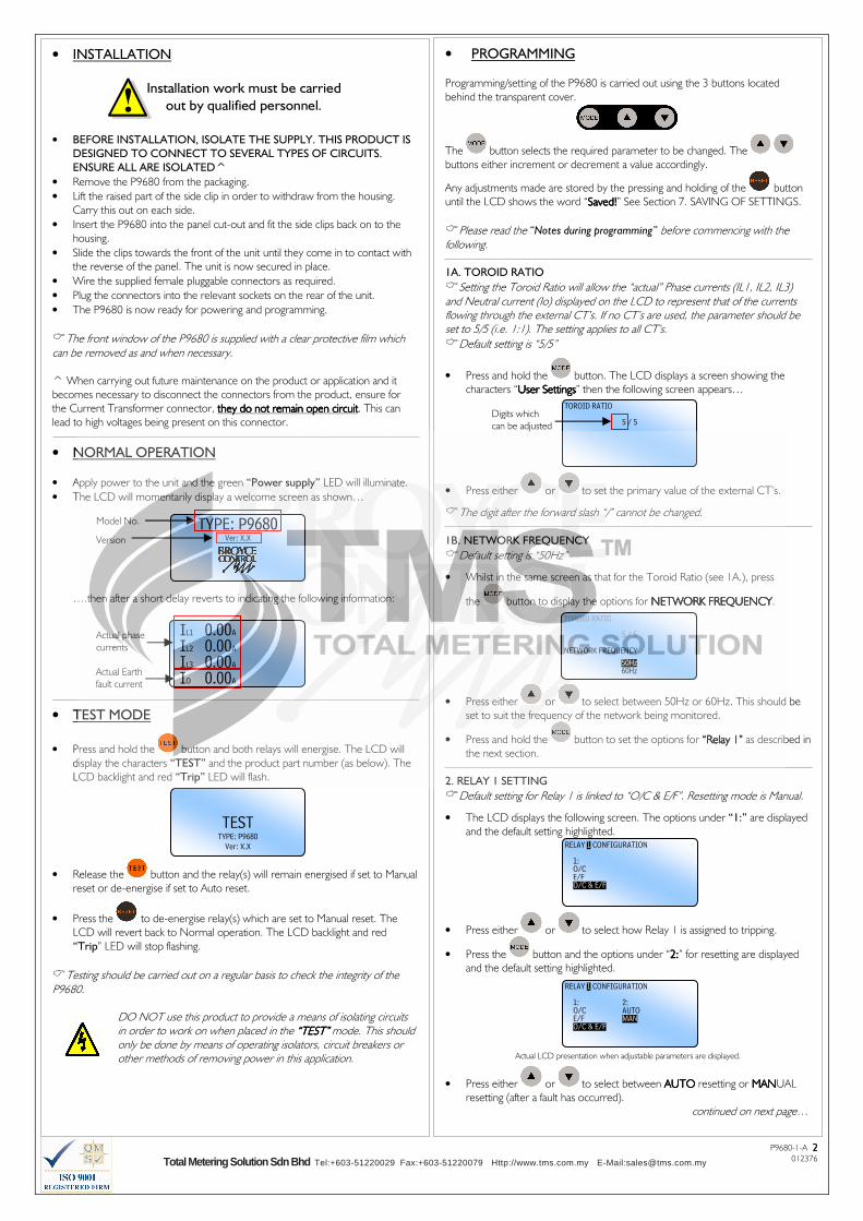
• PROGRAMMING
Programming/setting of the P9680 is carried out using the 3 buttons located
behind the transparent cover.
The button selects the required parameter to be changed. The
buttons either increment or decrement a value accordingly.
Any adjustments made are stored by the pressing and holding of the button
until the LCD shows the word “Saved!Saved!Saved!Saved!” See Section 7. SAVING OF SETTINGS.
�Please read the “Notes during programming” before commencing with the following.
1A. TOROID RATIO
�Setting the Toroid Ratio will allow the “actual” Phase currents (IL1, IL2, IL3) and Neutral current (Io) displayed on the LCD to represent that of the currents flowing through the external CT’s. If no CT’s are used, the parameter should be set to 5/5 (i.e. 1:1). The setting applies to all CT’s.
�Default setting is “5/5”
• Press and hold the button. The LCD displays a screen showing the
characters “User SettingsUser SettingsUser SettingsUser Settings” then the following screen appears…
• Press either or to set the primary value of the external CT’s.
�The digit after the forward slash “/” cannot be changed. 1B. NETWORK FREQUENCY
�Default setting is “50Hz”
• Whilst in the same screen as that for the Toroid Ratio (see 1A.), press
the button to display the options for NETWORK FREQUENCYNETWORK FREQUENCYNETWORK FREQUENCYNETWORK FREQUENCY.
• Press either or to select between 50Hz or 60Hz. This should be
set to suit the frequency of the network being monitored.
• Press and hold the button to set the options for “Relay 1” “Relay 1” “Relay 1” “Relay 1” as described in
the next section.
2. RELAY 1 SETTING
�Default setting for Relay 1 is linked to “O/C & E/F”. Resetting mode is Manual.
• The LCD displays the following screen. The options under “1:” are displayed
and the default setting highlighted.
• Press either or to select how Relay 1 is assigned to tripping.
• Press the button and the options under “2:2:2:2:” for resetting are displayed
and the default setting highlighted.
Actual LCD presentation when adjustable parameters are displayed.
• Press either or to select between AUTOAUTOAUTOAUTO resetting or MANMANMANMANUAL
resetting (after a fault has occurred).
continued on next page…
• INSTALLATION
• BEFORE INSTALLATION, ISOLATE THE SUPPLY. THIS PRODUCT IS
DESIGNED TO CONNECT TO SEVERAL TYPES OF CIRCUITS.
ENSURE ALL ARE ISOLATED^
• Remove the P9680 from the packaging.
• Lift the raised part of the side clip in order to withdraw from the housing.
Carry this out on each side.
• Insert the P9680 into the panel cut-out and fit the side clips back on to the
housing.
• Slide the clips towards the front of the unit until they come in to contact with
the reverse of the panel. The unit is now secured in place.
• Wire the supplied female pluggable connectors as required.
• Plug the connectors into the relevant sockets on the rear of the unit.
• The P9680 is now ready for powering and programming.
�The front window of the P9680 is supplied with a clear protective film which can be removed as and when necessary.
^ When carrying out future maintenance on the product or application and it
becomes necessary to disconnect the connectors from the product, ensure for
the Current Transformer connector, they do not remain open circuitthey do not remain open circuitthey do not remain open circuitthey do not remain open circuit. This can
lead to high voltages being present on this connector.
• NORMAL OPERATION
• Apply power to the unit and the green “Power supply” LED will illuminate.
• The LCD will momentarily display a welcome screen as shown…
….then after a short delay reverts to indicating the following information:
• TEST MODE
• Press and hold the button and both relays will energise. The LCD will
display the characters “TEST” and the product part number (as below). The
LCD backlight and red “Trip” LED will flash.
• Release the button and the relay(s) will remain energised if set to Manual
reset or de-energise if set to Auto reset.
• Press the to de-energise relay(s) which are set to Manual reset. The
LCD will revert back to Normal operation. The LCD backlight and red
“Trip” LED will stop flashing.
�Testing should be carried out on a regular basis to check the integrity of the P9680.
DO NOT use this product to provide a means of isolating circuits in order to work on when placed in the “TEST”“TEST”“TEST”“TEST” mode. This should only be done by means of operating isolators, circuit breakers or other methods of removing power in this application.
IL1 0.00A IL2 0.00A IL3 0.00A
IO 0.00A
Installation work must be carried
out by qualified personnel.
Actual phase
currents
Actual Earth
fault current
TEST TYPE: P9680
Ver: X.X
TOROID RATIO
5 / 5
RELAY 1 CONFIGURATION 1: O/C E/F O/C & E/F
Digits which
can be adjusted
TYPE: P9680 Ver: X.X
Model No.
Version
TOROID RATIO
5 / 5
NETWORK FREQUENCY
50Hz 60Hz
RELAY 1 CONFIGURATION 1: 2: O/C AUTO E/F MAN O/C & E/F
Total Metering Solution Sdn Bhd Tel:+603-51220029 Fax:+603-51220079 Http://www.tms.com.my E-Mail:[email protected]

P9680-1-A 3333 012376
6. OVERCURRENT & EARTH FAULT SUMMARY
�It is not possible to edit settings when these screens are displayed.
• Following the setting of “Earth Fault”, the LCD displays the “Overcurrent
Summary” screen showing a summary of the settings made during
programming. All settings are displayed. The selected CT ratio, Network
Frequency and Relay operation (following a Reset) information is also
displayed.
• Press and hold the button to display the
“Earth Fault Summary” screen.
7. SAVING OF SETTINGS
• If after viewing the Summary screens the settings are correct, press and hold
the button until the word “Saved.”“Saved.”“Saved.”“Saved.” appears. Any new settings are now
stored.
• The screen will revert back to Normal operation.
8. QUICK VIEW OF USER SETTINGS
�It is not possible to edit settings when these screens are displayed.
�This feature can also be activated with the front window closed!
• Press and hold the button to display the initial power up screen.
• Press the same button again to display the “Last Tripped Information” screen
(refer to the next section for further information on this feature).
• Press again to display the “Overcurrent Summary” screen.
• Press again to display the “Earth Fault Summary” screen.
• Press again to display the contact details for Broyce Control.
• Press again to revert back to Normal operation.
9. LAST TRIPPED INFORMATION
�This information is held in memory even if power is removed. If a new trip event occurs, this information will be overwritten.
This feature allows the user to view the key information relating to the last trip
condition. It is accessed as described in Section 8 above.
It highlights the cause of the trip (i.e. which phase for example), the level of
current at the time the trip occurred; the triggering method (Low-set or High-set)
and which relays were activated. An example is shown below.
Notes during programming
�If during programming it is necessary to abort, press the button briefly.
�Pressing and holding either or for >1sec. will increment or decrement the new value at a quicker rate.
�Stepping through each User Setting screen is performed by pressing and
holding the button until the desired screen is displayed.
Short presses of the button will allow further editable settings to be changed within a specific screen.
�If the user remains in a setting or summary screen where no adjustments or button presses are made within a certain period, the screen will revert back to Normal operation. Additionally, any settings that have been made but not stored will not be saved.
�”O/C” refers to Overcurrent and “E/F” refers to Earth fault.
• PROGRAMMING (continued)
• Press and hold the button to set the options for “Relay 2” Relay 2” Relay 2” Relay 2” as described in
the next section.
3. RELAY 2 SETTING
�Default setting for Relay 2 is linked to “O/C & E/F” and energising at the end of the time out period. Resetting mode is Auto.
• Setting of “Relay 2” is carried out in a similar manner as “Relay 1”, however it
is necessary to assign the relay to either energise at the start (S) or end (E) of
the time out period.
Actual LCD presentation when adjustable parameters are displayed.
• Press and hold the button to set the options for “OVERCURRENT” “OVERCURRENT” “OVERCURRENT” “OVERCURRENT” as
described in the next section.
4. OVERCURRENT SETTING
�The description for the Curves is abbreviated when displayed on the screen. Refer to “IDMT Characteristic Curves” for further explanation.
�Default settings for Overcurrent are shown in the last LCD screen example in this section.
• Settings for Overcurrent are displayed in turn following subsequent presses of
the button. The Low-set trip current (I>) is displayed first.
• Press either or to change the current.
• Press the button to select the remaining settings and use the and
buttons to change them.
Actual LCD presentation when adjustable parameters are displayed.
Screen example above also shows the default settings for OVERCURRENT.
• Press and hold the button to set the options for “EARTH FAULT” “EARTH FAULT” “EARTH FAULT” “EARTH FAULT” as
described in the next section.
�If the Curve in selection “2:” is set to Definite Time, then selection “3:” will display “3: t>” and the required delay can then be set.
�If High-set is set to Disable in selection “4:”, then I>> or t>> cannot be adjusted.
5. EARTH FAULT SETTING
�Default settings for Earth Fault are shown in the LCD screen example in this section.
• Settings for Earth Fault are carried out in the same manner as described for
Overcurrent.
Screen example showing the default settings for EARTH FAULT.
• Press and hold the button to see a summary of the “OVERCURRENT“OVERCURRENT“OVERCURRENT“OVERCURRENT””””
then “EARTH FAULT”“EARTH FAULT”“EARTH FAULT”“EARTH FAULT” settings as described in the next section.
�If the Curve in selection “2:” is set to Definite Time, then selection “3:” will display “3: to>” and the required delay can then be set.
�If High-set is set to Disable in selection “4:”, then Io>> or to>> cannot be adjusted.
O/C SETTING Low set 1: I> 5.00A
O/C SUMMARY I> 5.00A NI 3/10 k> 0.1 I>>50.00A t>>0.05s R1 = MAN R2 = AUTO (E) CT=5:5, FREQ=50Hz
E/F SUMMARY Io> 2.00A NI 3/10 ko> 0.1 Io>>10.00A to>>0.05s R1 = MAN R2 = AUTO (E) CT=5:5, FREQ=50Hz
RELAY 2 CONFIGURATION 1: 2: O/C AUTO (E) E/F MAN (E) O/C & E/F AUTO (S) MAN (S)
O/C SETTING Low Set: 1: I> 5.00A 2: Curve NI 3/10 3: k> 0.1 High Set: 4: I>> 50.00A 5: t>> 0.05s
E/F SETTING Low Set: 1: Io> 2.00A 2: Curve NI 3/10 3: k> 0.1 High Set: 4: Io>> 10.00A 5: to>> 0.05s
IL1 20.70A I>> IL2 89.00A R1 R2
IL3 27.50A IO 0.00A
Phase which
caused the
trip to occur
(i.e. L2)
Level of
current on
other inputs
at time of trip
Level which
was triggered
(i.e. High-set)
Relays that
were
activated at
trip
The letter in brackets refers to
whether Relay 2 has been set
to trigger at the start or end of
the time out period.
(E) = EEEEnd of time out
(S) = SSSStart of time out
Either abbreviation can appear
after the word MAN or AUTO
See Section 3. RELAY 2 SETTING
Total Metering Solution Sdn Bhd Tel:+603-51220029 Fax:+603-51220079 Http://www.tms.com.my E-Mail:[email protected]

P9680-1-A 4444 012376
• TRIPPING MODES
1. OVERCURRENT
• A fault which develops on a phase will be indicated by an increase in current
reading on the LCD. When the level of current exceeds the Low-set setting,
the phase at fault will be highlighted by the digits flashing.
• The LCD backlight will flash.
• Relay 2 will energise if assigned to Overcurrent and set to energise at the start
of the time out period (See Section 3. RELAY 2 SETTING).
• The characters “I>” will display to indicate the Low-set has been triggered.
• If the current continues to increase above the High-set setting, the characters
“I>” will change and display “I>>” to indicate the High-set has been
triggered.
• When the unit finally trips, the digits of the phase at fault will stop flashing and
remain highlighted. This allows the user to see which phase was at fault and
caused the unit to trip.
• The red “Tripped”“Tripped”“Tripped”“Tripped” LED will also flash.
• The relays which energised are also displayed on the screen after tripping.
• Press to reset and return the unit back to normal operation (assuming
the fault has been cleared). The LCD reverts back to displaying the normal
system currents and the red “Tripped”“Tripped”“Tripped”“Tripped” LED stops flashing.
�If either relay is set for Auto resetting, then they would have de-energised after the fault had cleared. The corresponding relay ident (i.e. R1 and/or R2) on the display would also disappear. Pressing the “RESET”“RESET”“RESET”“RESET” button will only clear the LCD. If either relay is set for Manual resetting, then pressing the “RESET”“RESET”“RESET”“RESET” button will de-energise the relay(s) and clear the LCD.
In the event of an Overcurrent condition, the basic sequence of events is
shown below.
�Assuming High-set trip is enabled.
IL1 20.70A I> IL2 40.00A
IL3 27.50A IO 0.00A
Phase with fault
2. EARTH FAULT
• When an Earth fault occurs causing a flow in current through the Neutral, an
increase in current reading on the LCD will occur. When the level of current
exceeds the Low-set setting, the reading will be highlighted by the digits
flashing.
• The LCD backlight will flash.
• Relay 2 will energise if assigned to Earth fault and set to energise at the start of
the time out period (See Section 3. RELAY 2 SETTING).
• The characters “Io>” will display to indicate the Low-set has been triggered.
• If the current continues to increase above the High-set setting, the characters
“Io>” will change and display “Io>>” to indicate the High-set has been
triggered.
• When the unit finally trips, the digits will stop flashing and remain highlighted.
This allows the user to see what caused the unit to trip.
• The red “Tripped”“Tripped”“Tripped”“Tripped” LED will also flash.
• The relays which energised are also displayed on the screen after tripping.
• Press to reset and return the unit back to normal operation (assuming
the fault has been cleared). The LCD reverts back to displaying the normal
system currents and the red “Tripped”“Tripped”“Tripped”“Tripped” LED stops flashing.
� If either relay is set for Auto resetting, then they would have de-energised after the fault had cleared. The corresponding relay ident (i.e. R1 and/or R2) on the display would also disappear. Pressing the “RESET”“RESET”“RESET”“RESET” button will only clear the LCD. If either relay is set for Manual resetting, then pressing the “RESET”“RESET”“RESET”“RESET” button will de-energise the relay(s) and clear the LCD. In the event of an Earth fault condition, the basic sequence of events is shown
below.
�Assuming High-set trip is enabled.
IL1 20.70A I>> IL2 89.00A R1 R2
IL3 27.50A IO 0.00A
IL1 0.00A IL2 0.00A IL3 0.00A Io>
IO 1.00A
IL1 0.00A IL2 0.00A
IL3 0.00A Io>>
IO 8.00A R1
Low-set
triggered
High-set
triggered
Relay(s) which
energised on
tripping
Low-set
triggered
High-set
triggered
Relay(s) which
energised on
tripping
Earth fault
current
OVERCURRENT
fault occurs
Low-set I>
triggered
Run IDMT or DT
delay t>
Run DT delay
t>>
High-set
I>>
triggered?
N
Y
TRIP!
Delay
t>
complete?
N
Y
Delay
t>>
complete?
N
Y
START
EARTH FAULT
occurs
Low-set Io>
triggered
Run IDMT or DT
delay to>
Run DT delay
to>>
High-set
Io>>
triggered?
N
Y
TRIP!
Delay
to>
complete?
N
Y
Delay
to>>
complete?
N
Y
START
Total Metering Solution Sdn Bhd Tel:+603-51220029 Fax:+603-51220079 Http://www.tms.com.my E-Mail:[email protected]
P9680-1-A 5555 012376
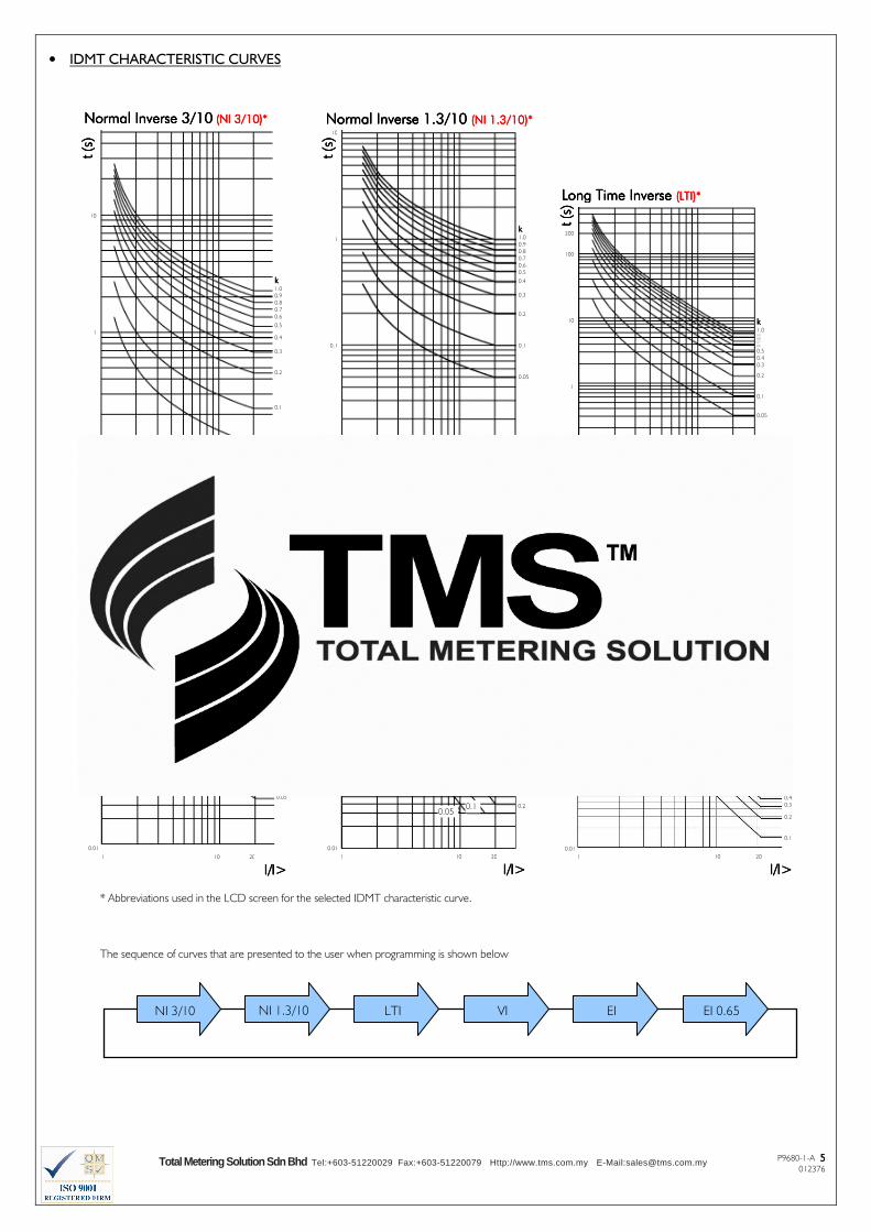
• IDMT CHARACTERISTIC CURVES
* Abbreviations used in the LCD screen for the selected IDMT characteristic curve.
The sequence of curves that are presented to the user when programming is shown below
kkkk 1.0
0.9
0.8
0.7
0.6
0.5
0.4
0.3
0.2
0.1
0.05
Normal Inverse 1.3/10 Normal Inverse 1.3/10 Normal Inverse 1.3/10 Normal Inverse 1.3/10 (NI 1.3/10)*(NI 1.3/10)*(NI 1.3/10)*(NI 1.3/10)*
1 10 20
I/I>I/I>I/I>I/I>
kkkk 1.0
0.9
0.8
0.7
0.6
0.5
0.4
0.3
0.2
0.1
0.05
t t t t (s)
(s)
(s)
(s) 10
1
0.1
0.01
t t t t (s)
(s)
(s)
(s)
Normal Inverse 3/10Normal Inverse 3/10Normal Inverse 3/10Normal Inverse 3/10 (NI 3/10)*(NI 3/10)*(NI 3/10)*(NI 3/10)*
t t t t (s)
(s)
(s)
(s)
kkkk 1.0
0.9
0.8
0.7
0.6
0.5
0.4
0.3
0.2
0.1
0.05
10
1
0.1
1 10 20
I/I>I/I>I/I>I/I>
Long Time Inverse Long Time Inverse Long Time Inverse Long Time Inverse (LTI)*(LTI)*(LTI)*(LTI)*
.
200
100
10
1
0.1
kkkk 1.0 0.9
0.8
0.7
0.6
0.5
0.4
0.3
0.2
0.1
0.05
t t t t (s)
(s)
(s)
(s)
1 10 20
I/I>I/I>I/I>I/I>
Very Inverse Very Inverse Very Inverse Very Inverse (VI)*(VI)*(VI)*(VI)*
1 10 20
I/I>I/I>I/I>I/I>
kkkk 1.0 0.9
0.8
0.7
0.6
0.5
0.4
0.3
0.2
0.1
0.05
10
1
0.1
0.01
t t t t (s)
(s)
(s)
(s)
Extremely Inverse Extremely Inverse Extremely Inverse Extremely Inverse (EI)*(EI)*(EI)*(EI)*
kkkk 0.9 0.8
0.7
0.6
0.5
0.4
0.3
0.2
100
10
1
0.1
0.01
t t t t (s)
(s)
(s)
(s)
1.0
0
0.1 0.05
1 10 20
I/I>I/I>I/I>I/I>
Extremely Inverse Extremely Inverse Extremely Inverse Extremely Inverse (EI 0.65)*(EI 0.65)*(EI 0.65)*(EI 0.65)*
kkkk
0.9
0.8
0.7
0.6
0.5
0.4
0.3
0.2
0.1
1 10 20
I/I>I/I>I/I>I/I>
1000
100
10
1
0.1
0.01
1.0
0
NI 3/10
NI 1.3/10
LTI
EI
EI 0.65
VI
t t t t (s)
(s)
(s)
(s)
Total Metering Solution Sdn Bhd Tel:+603-51220029 Fax:+603-51220079 Http://www.tms.com.my E-Mail:[email protected]

P9680-1-A 6666 012376
Electrical life: ≥ 150,000 ops at rated load
Dielectric voltage: 2kV AC (rms) IEC 60947-1
Rated impulse
withstand voltage: 4kV (1.2 / 50µS) IEC 60664
Max. DC Load Breaking Capacity Electrical Endurance
Housing: Flame retardant Lexan
Protection: IP55 / IP20 (rear)
Weight: ≈ 600g
Mounting: Panel mounting. Cut-out = 91 x 91mm (± 0.5mm)
Max. panel thickness: 12mm
Terminal type: UL94 V-0 rated pluggable and re-wireable female
connectors comprising:
2-way (Power supply 1, 2)
6-way (Relay contacts 3….8)
8-way (Phase current and neutral inputs 9….16) Terminal conductor size: 0.05 - 2.5mm2 (30 - 12AWG)
Recommended tightening
torque: 4.4in lb (0.5Nm)
Wire stripping length: 0.24 – 0.30in (6 – 7.5mm)
Approvals: Conforms to IEC. CE and and RoHS Compliant.
EMC: Immunity: EN/IEC 61000-6-2
Emissions: EN/IEC 61000-6-4
Generic: IEC 60255-26 (EMC), IEC 255-3, IEC
60255-151
( ) Bold digits in brackets refer to terminal numbers on the rear of the unit.
Options:
The P9600 range also includes individual Overcurrent or Earth fault relays
available with either IDMT or DT characteristics. Please refer to separate data
sheets.
• TECHNICAL SPECIFICATION
Supply voltage Un (1, 2): 85 – 265VAC/85 - 370VDC
18 – 57VAC/18 – 75VDC
(Voltage range should be specified at time of ordering) Rated frequency: 50/60Hz (AC Supplies)
Isolation: Over voltage cat. III
Rated impulse
withstand voltage: 4kV (1.2 / 50µS) IEC 60664
Power consumption: 3W max.
Rated current input In: 5A (directly connected)
Rated frequency: 50/60Hz
Burden: <0.4VA @ In
Overload: 4 x In (continuous)
External CT’s (9……16): Class P recommended. (with 5A secondary)
Maximum CT primary
current rating: 5000A
Overcurrent settings:
Low-set trip (I>): 0.50 – 10.00A (10 – 200%)
Low-set time multiplier (k>): 0.05 – 1.00
Low-set definite time (t>): 0.05 – 100s
High-set trip (I>>): 0.5 – 100A (10 – 2000%) or disable
High-set definite time (t>>): 0.05 – 2.5s
Earth fault settings:
Low-set trip (Io>): 0.10 – 5.00A (2 – 100%)
Low-set time multiplier (ko>): 0.05 – 1.00
Low-set definite time (to>): 0.05 – 100s
High-set trip (Io>>): 0.10 – 50.00A (2 – 1000%) or disable
High-set definite time (to>>): 0.05 – 2.5s
Pick up value: +2% of trip setting
Accuracy:
Protection thresholds: ± 5%
Time delay (DT): ± 5% (with a minimum of 50mS)
Time delay (IDMT): ± 5% (with a minimum of 50mS and I > 1.2 x
set-trip)
Actual phase current: ± 1% of rated current In
Actual Earth fault current: ± 1% of rated current In
Display update time: <1 sec.
Repeat accuracy: ± 0.5% @ constant conditions
Ambient temperature: -10 to +60°C
Relative humidity: +95%
Output:
(RL1 - 3, 4, 5): 1 x SPDT relay
(RL2 - 6, 7, 8): 1 x SPDT relay
Output rating: AC1 250V 8A (2000VA)
AC15 250V 5A (1250VA)
DC1 25V 8A (200W)
• CONNECTION DIAGRAM
L1
L2
L3
N
A1 A2
RL1 RL2
Aux.
1 2 3 4 5 6 7
9
8
10 11 12 1314 1615
IL1 IL2 IL3 IN
• DIMENSIONS
96
96
MADE IN U.K.
10 100
89.596
Front view Side view
All dimensions are in mm.
Total Metering Solution Sdn Bhd Tel:+603-51220029 Fax:+603-51220079 Http://www.tms.com.my E-Mail:[email protected]