type rf emi/rfi filters - mte corporation
TRANSCRIPT
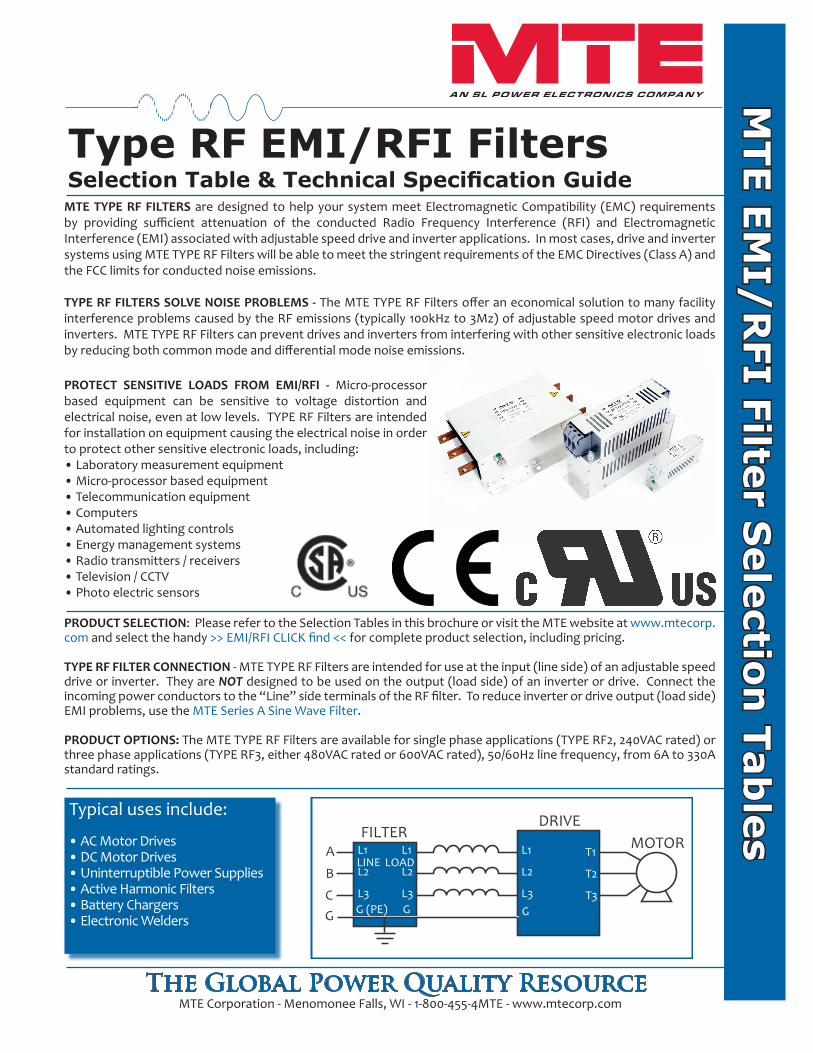
PROTECT SENSITIVE LOADS FROM EMI/RFI - Micro-processor based equipment can be sensitive to voltage distortion and electrical noise, even at low levels. TYPE RF Filters are intended for installation on equipment causing the electrical noise in order to protect other sensitive electronic loads, including:• Laboratory measurement equipment• Micro-processor based equipment• Telecommunication equipment• Computers• Automated lighting controls• Energy management systems• Radio transmitters / receivers• Television / CCTV• Photo electric sensors
Type RF EMI/RFI FiltersSelection Table & Technical Specification Guide
MTE E
MI/
RFI F
ilter S
ele
ction
Tab
les
MTE Corporation - Menomonee Falls, WI - 1-800-455-4MTE - www.mtecorp.com
Typical uses include:
• AC Motor Drives • DC Motor Drives • Uninterruptible Power Supplies • Active Harmonic Filters • Battery Chargers • Electronic Welders
PRODUCT SELECTION: Please refer to the Selection Tables in this brochure or visit the MTE website at www.mtecorp.com and select the handy >> EMI/RFI CLICK find << for complete product selection, including pricing.
TYPE RF FILTER CONNECTION - MTE TYPE RF Filters are intended for use at the input (line side) of an adjustable speed drive or inverter. They are NOT designed to be used on the output (load side) of an inverter or drive. Connect the incoming power conductors to the “Line” side terminals of the RF filter. To reduce inverter or drive output (load side) EMI problems, use the MTE Series A Sine Wave Filter.
PRODUCT OPTIONS: The MTE TYPE RF Filters are available for single phase applications (TYPE RF2, 240VAC rated) or three phase applications (TYPE RF3, either 480VAC rated or 600VAC rated), 50/60Hz line frequency, from 6A to 330A standard ratings.
The Global Power Quality Resource
FILTERDRIVE
A
B
CG
L1
L2
L3G
T1
T2
T3
L1
L2
L3G
L1
L2
L3G (PE)
LINE LOAD
MOTOR
MTE TYPE RF FILTERS are designed to help your system meet Electromagnetic Compatibility (EMC) requirements by providing sufficient attenuation of the conducted Radio Frequency Interference (RFI) and Electromagnetic Interference (EMI) associated with adjustable speed drive and inverter applications. In most cases, drive and inverter systems using MTE TYPE RF Filters will be able to meet the stringent requirements of the EMC Directives (Class A) and the FCC limits for conducted noise emissions.
TYPE RF FILTERS SOLVE NOISE PROBLEMS - The MTE TYPE RF Filters offer an economical solution to many facility interference problems caused by the RF emissions (typically 100kHz to 3Mz) of adjustable speed motor drives and inverters. MTE TYPE RF Filters can prevent drives and inverters from interfering with other sensitive electronic loads by reducing both common mode and differential mode noise emissions.
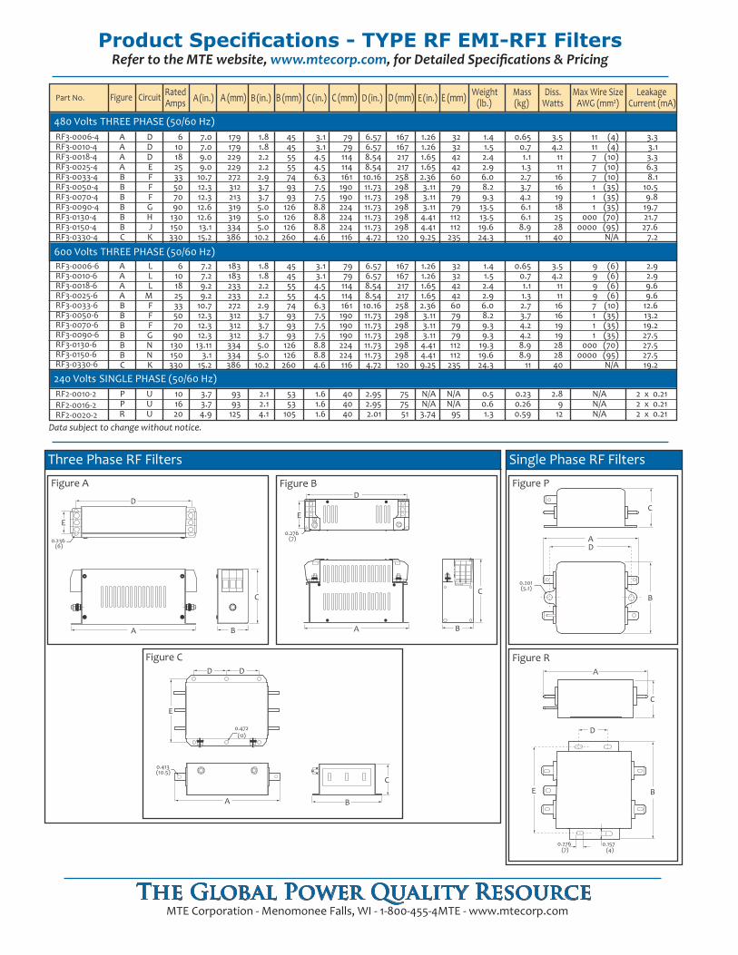
Product Specifications - TYPE RF EMI-RFI FiltersRefer to the MTE website, www.mtecorp.com, for Detailed Specifications & Pricing
Data subject to change without notice.
RF2-0010-2RF2-0016-2RF2-0020-2
240 Volts SINGLE PHASE (50/60 Hz)
RF3-0006-4RF3-0010-4RF3-0018-4RF3-0025-4RF3-0033-4RF3-0050-4RF3-0070-4RF3-0090-4RF3-0130-4RF3-0150-4RF3-0330-4
RF3-0006-6RF3-0010-6RF3-0018-6RF3-0025-6RF3-0033-6RF3-0050-6RF3-0070-6RF3-0090-6RF3-0130-6RF3-0150-6RF3-0330-6
Rated A (in.) A (mm) B (in.) B (mm) C (in.) C (mm) D (in.) D (mm) E (in.) E (mm) Weight Mass Diss. Max Wire Size LeakagePart No. Figure Amps (lb.) (kg) Watts AWG (mm²) Current (mA)
480 Volts THREE PHASE (50/60 Hz)
600 Volts THREE PHASE (50/60 Hz)
Circuit
610182533507090
130150330
7.07.09.09.0
10.712.312.312.612.613.115.2
179179229229272312213319319334386
1.81.82.22.22.93.73.75.05.05.0
10.2
45455555749393
126126126260
3.13.14.54.56.37.57.58.88.88.84.6
6.576.578.548.54
10.1611.7311.7311.7311.7311.734.72
167167217217
258298298298298298120
1.261.261.651.652.363.113.113.11
4.414.419.25
3232424260797979112112
235
1.41.52.42.96.08.29.3
13.513.519.624.3
0.650.71.11.32.73.74.26.16.18.9
11
3.54.2
111116161918252840
11 (4)11 (4)7 (10)7 (10)7 (10)1 (35)1 (35)1 (35)
000 (70)0000 (95)
N/A
3.33.13.36.38.1
10.59.8
19.721.727.6
7.2
7979114114161190190224224224116
AAAABBBBBBC
DDDEFFFGHJK
610182533507090
130150330
7.27.29.29.2
10.712.312.312.3
13.113.1
15.2
183183233233272312312312334334386
1.81.82.22.22.93.73.73.75.05.0
10.2
4545555574939393
126126260
3.13.14.54.56.37.57.57.58.88.84.6
6.576.578.548.54
10.1611.7311.7311.7311.7311.734.72
167167217217
258298298298298298120
1.261.261.651.652.363.113.113.11
4.414.419.25
3232424260797979112112
235
1.41.52.42.96.08.29.39.3
19.319.624.3
0.650.71.11.32.73.74.24.28.98.9
11
3.54.2
111116161919282840
9 (6)9 (6)9 (6)9 (6)7 (10)1 (35)1 (35)1 (35)
000 (70)0000 (95)
N/A
2.92.99.69.6
12.613.219.227.527.527.519.2
7979114114161190190190224224116
AAAABBBBBBC
LLL
MFFFGNNK
101620
3.73.74.9
9393
125
2.12.14.1
5353
105
1.61.61.6
2.952.952.01
757551
N/AN/A3.74
N/AN/A
95
0.50.61.3
0.230.260.59
2.89
12
N/AN/AN/A
2 x 0.212 x 0.212 x 0.21
404040
PPR
UUU
0.413(10.5)
B
C
E
D D
0.472(12)
A
Figure C
Three Phase RF Filters
E
D
A
0.236(6)
B
C
Figure A
E
D
A
0.276(7)
B
C
Figure B
0.201(5.1)
C
DA
B
Figure P
Single Phase RF Filters
0.276(7)
C
D
A
B
0.157(4)
E
Figure R
MTE Corporation - Menomonee Falls, WI - 1-800-455-4MTE - www.mtecorp.comThe Global Power Quality Resource
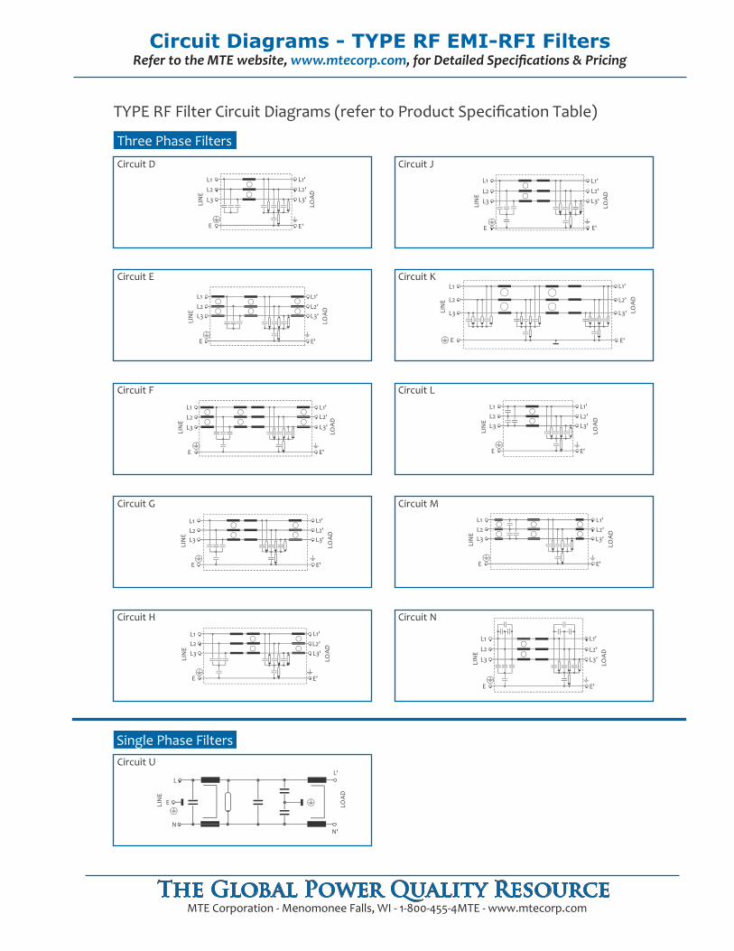
Circuit Diagrams - TYPE RF EMI-RFI FiltersRefer to the MTE website, www.mtecorp.com, for Detailed Specifications & Pricing
MTE Corporation - Menomonee Falls, WI - 1-800-455-4MTE - www.mtecorp.comThe Global Power Quality Resource
ENIL
DA
OL
L1
L2L3
E E'
L1'L2'L3'
ENIL
DA
OL
L1L2L3
E E'
L1'L2'L3'
Circuit D
Three Phase Filters
ENIL
DA
OL
L1L2L3
L1'L2'L3'
E E'
Circuit E
Circuit F
ENIL
DA
OL
L1L2L3
E E'
L1'L2'L3'
ENIL
DA
OL
L1L2L3
E E'
L1'L2'L3'
Circuit H
Circuit J
Circuit K
ENIL
DA
OL
L1L2L3
E E'
L1'L2'L3'
ENIL
DA
OL
L1
L2
L3
E E'
L1'
L2'
L3'
Circuit L
ENIL
DA
OL
L1L2L3
E E'
L1'L2'L3'
Circuit M
ENIL
DA
OL
L1
L2
L3
E E'
L1'
L2'L3'
Circuit N
ENIL
DA
OL
L1L2L3
E E'
L1'L2'L3'
Circuit G
ENIL
DA
OL
L
N
L'
E
N'
Single Phase FiltersCircuit U
TYPE RF Filter Circuit Diagrams (refer to Product Specification Table)
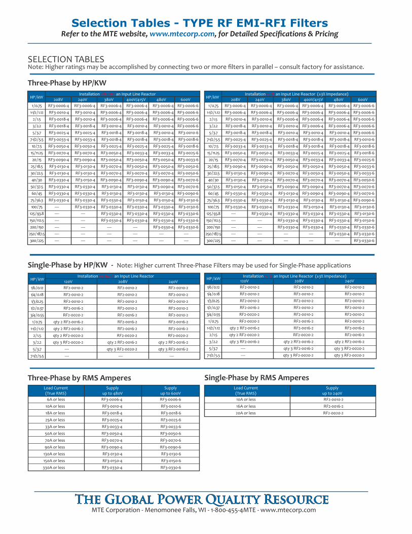
Selection Tables - TYPE RF EMI-RFI FiltersRefer to the MTE website, www.mtecorp.com, for Detailed Specifications & Pricing
MTE Corporation - Menomonee Falls, WI - 1-800-455-4MTE - www.mtecorp.comThe Global Power Quality Resource
Single-Phase by RMS Amperes
Three-Phase by HP/KW
SELECTION TABLES Note: Higher ratings may be accomplished by connecting two or more filters in parallel – consult factory for assistance.
Single-Phase by HP/KW - Note: Higher current Three-Phase Filters may be used for Single-Phase applications
Three-Phase by RMS Amperes
208V 240V 380V 400V/415V 480V 600V
Installation without an Input Line Reactor120V 208V 240V
RF3-0006-4
RF3-0010-4
RF3-0018-4
RF3-0025-4
RF3-0033-4
RF3-0050-4
RF3-0070-4
RF3-0090-4
RF3-0130-4
RF3-0150-4
RF3-0330-4
RF3-0006-6
RF3-0010-6
RF3-0018-6
RF3-0025-6
RF3-0033-6
RF3-0050-6
RF3-0070-6
RF3-0090-6
RF3-0130-6
RF3-0150-6
RF3-0330-6
6A or less
10A or less
18A or less
25A or less
33A or less
50A or less
70A or less
90A or less
130A or less
150A or less
330A or less
Load Current(True RMS)
Supplyup to 480V
Supplyup to 600V
RF2-0010-2
RF2-0016-2
RF2-0020-2
10A or less
16A or less
20A or less
Load Current(True RMS)
Supplyup to 240V
1/6 / 0.12
1/4 / 0.18
1/3 /0.25
1/2 / 0.37
3/4 / 0.55
1 / 0.75
1-1/2 / 1.12
2 / 1.5
3 / 2.2
5 / 3.7
7-1/2 / 5.5
RF2-0010-2
RF2-0010-2
RF2-0010-2
RF2-0016-2
RF2-0020-2
qty 2 RF2-0016-2
qty 2 RF2-0016-2
qty 2 RF2-0020-2
qty 3 RF2-0020-2
----
----
RF2-0010-2
RF2-0010-2
RF2-0010-2
RF2-0010-2
RF2-0016-2
RF2-0016-2
RF2-0016-2
RF2-0020-2
qty 2 RF2-0016-2
qty 3 RF2-0020-2
----
RF2-0010-2
RF2-0010-2
RF2-0010-2
RF2-0010-2
RF2-0010-2
RF2-0016-2
RF2-0016-2
RF2-0020-2
qty 2 RF2-0016-2
qty 3 RF2-0016-2
----
HP / kW 120V 208V 240V1/6 / 0.12
1/4 / 0.18
1/3 /0.25
1/2 / 0.37
3/4 / 0.55
1 / 0.75
1-1/2 / 1.12
2 / 1.5
3 / 2.2
5 / 3.7
7-1/2 / 5.5
RF2-0010-2
RF2-0010-2
RF2-0010-2
RF2-0016-2
RF2-0020-2
RF2-0020-2
qty 2 RF2-0016-2
qty 2 RF2-0020-2
qty 3 RF2-0016-2
----
----
RF2-0010-2
RF2-0010-2
RF2-0010-2
RF2-0010-2
RF2-0010-2
RF2-0016-2
RF2-0016-2
RF2-0020-2
qty 2 RF2-0016-2
qty 3 RF2-0016-2
qty 3 RF2-0020-2
RF2-0010-2
RF2-0010-2
RF2-0010-2
RF2-0010-2
RF2-0010-2
RF2-0010-2
RF2-0016-2
RF2-0016-2
qty 2 RF2-0016-2
qty 3 RF2-0020-2
qty 3 RF2-0020-2
HP / kW
1 / 0.75
1-1/2 / 1.12
2 / 1.5
3 / 2.2
5 / 3.7
7-1/2 / 5.5
10 / 7.5
15 / 11.25
20 / 15
25 / 18.5
30 / 22.5
40 / 30
50 / 37.5
60 / 45
75 / 56.3
100 / 75
125 / 93.8
150 / 112.5
200 / 150
250 / 187.5
300 / 225
HP / kW
RF3-0006-4
RF3-0010-4
RF3-0018-4
RF3-0018-4
RF3-0025-4
RF3-0033-4
RF3-0050-4
RF3-0070-4
RF3-0090-4
RF3-0130-4
RF3-0130-4
RF3-0330-4
RF3-0330-4
RF3-0330-4
RF3-0330-4
----
----
----
----
----
----
Installation without an Input Line Reactor
RF3-0006-4
RF3-0010-4
RF3-0010-4
RF3-0018-4
RF3-0025-4
RF3-0033-4
RF3-0050-4
RF3-0070-4
RF3-0090-4
RF3-0130-4
RF3-0130-4
RF3-0150-4
RF3-0330-4
RF3-0330-4
RF3-0330-4
RF3-0330-4
----
----
----
----
----
RF3-0006-4
RF3-0006-4
RF3-0006-4
RF3-0010-4
RF3-0018-4
RF3-0018-4
RF3-0025-4
RF3-0050-4
RF3-0050-4
RF3-0070-4
RF3-0070-4
RF3-0090-4
RF3-0130-4
RF3-0130-4
RF3-0330-4
RF3-0330-4
RF3-0330-4
RF3-0330-4
----
----
----
RF3-0006-4
RF3-0006-4
RF3-0006-4
RF3-0010-4
RF3-0018-4
RF3-0018-4
RF3-0025-4
RF3-0033-4
RF3-0050-4
RF3-0050-4
RF3-0070-4
RF3-0090-4
RF3-0130-4
RF3-0130-4
RF3-0150-4
RF3-0330-4
RF3-0330-4
RF3-0330-4
----
----
----
RF3-0006-4
RF3-0006-4
RF3-0006-4
RF3-0010-4
RF3-0010-4
RF3-0018-4
RF3-0025-4
RF3-0033-4
RF3-0050-4
RF3-0050-4
RF3-0070-4
RF3-0090-4
RF3-0090-4
RF3-0130-4
RF3-0150-4
RF3-0330-4
RF3-0330-4
RF3-0330-4
RF3-0330-4
----
----
RF3-0006-6
RF3-0006-6
RF3-0006-6
RF3-0006-6
RF3-0010-6
RF3-0018-6
RF3-0018-6
RF3-0025-6
RF3-0033-6
RF3-0050-6
RF3-0050-6
RF3-0070-6
RF3-0070-6
RF3-0090-6
RF3-0130-6
RF3-0130-6
RF3-0330-6
RF3-0330-6
RF3-0330-6
----
----
Installation with an Input Line Reactor (≥3% Impedance)
Installation with an Input Line Reactor (≥3% Impedance)208V 240V 380V 400V/415V 480V 600V
1 / 0.75
1-1/2 / 1.12
2 / 1.5
3 / 2.2
5 / 3.7
7-1/2 / 5.5
10 / 7.5
15 / 11.25
20 / 15
25 / 18.5
30 / 22.5
40 / 30
50 / 37.5
60 / 45
75 / 56.3
100 / 75
125 / 93.8
150 / 112.5
200 / 150
250 / 187.5
300 / 225
RF3-0006-4
RF3-0006-4
RF3-0010-4
RF3-0018-4
RF3-0018-4
RF3-0025-4
RF3-0033-4
RF3-0050-4
RF3-0070-4
RF3-0090-4
RF3-0130-4
RF3-0130-4
RF3-0150-4
RF3-0330-4
RF3-0330-4
RF3-0330-4
----
----
----
----
----
RF3-0006-4
RF3-0006-4
RF3-0010-4
RF3-0010-4
RF3-0018-4
RF3-0025-4
RF3-0033-4
RF3-0050-4
RF3-0070-4
RF3-0090-4
RF3-0090-4
RF3-0130-4
RF3-0150-4
RF3-0330-4
RF3-0330-4
RF3-0330-4
RF3-0330-4
----
----
----
----
RF3-0006-4
RF3-0006-4
RF3-0006-4
RF3-0010-4
RF3-0010-4
RF3-0018-4
RF3-0018-4
RF3-0033-4
RF3-0050-4
RF3-0050-4
RF3-0070-4
RF3-0070-4
RF3-0090-4
RF3-0130-4
RF3-0130-4
RF3-0330-4
RF3-0330-4
RF3-0330-4
RF3-0330-4
----
----
RF3-0006-4
RF3-0006-4
RF3-0006-4
RF3-0006-4
RF3-0010-4
RF3-0018-4
RF3-0018-4
RF3-0025-4
RF3-0033-4
RF3-0050-4
RF3-0050-4
RF3-0070-4
RF3-0090-4
RF3-0090-4
RF3-0130-4
RF3-0150-4
RF3-0330-4
RF3-0330-4
RF3-0330-4
----
----
RF3-0006-4
RF3-0006-4
RF3-0006-4
RF3-0006-4
RF3-0010-4
RF3-0018-4
RF3-0018-4
RF3-0025-4
RF3-0033-4
RF3-0050-4
RF3-0050-4
RF3-0070-4
RF3-0070-4
RF3-0090-4
RF3-0130-4
RF3-0130-4
RF3-0330-4
RF3-0330-4
RF3-0330-4
RF3-0330-4
----
RF3-0006-6
RF3-0006-6
RF3-0006-6
RF3-0006-6
RF3-0006-6
RF3-0010-6
RF3-0018-6
RF3-0018-6
RF3-0025-6
RF3-0033-6
RF3-0033-6
RF3-0050-6
RF3-0070-6
RF3-0070-6
RF3-0090-6
RF3-0130-6
RF3-0130-6
RF3-0150-6
RF3-0330-6
RF3-0330-6
RF3-0330-6
HP / kW
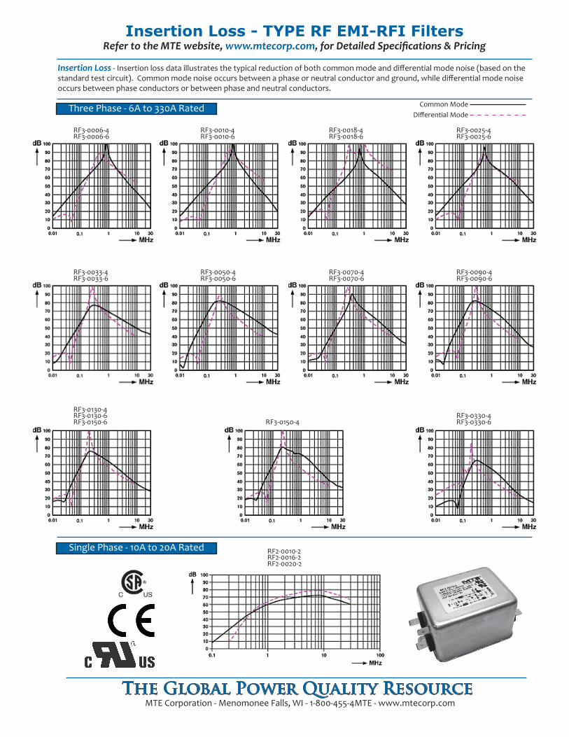
Insertion Loss - TYPE RF EMI-RFI FiltersRefer to the MTE website, www.mtecorp.com, for Detailed Specifications & Pricing
MTE Corporation - Menomonee Falls, WI - 1-800-455-4MTE - www.mtecorp.comThe Global Power Quality Resource
RF2-0010-2RF2-0016-2RF2-0020-2
RF3-0025-4RF3-0025-6
RF3-0018-4RF3-0018-6
RF3-0010-4RF3-0010-6
RF3-0150-4RF3-0330-4RF3-0330-6
RF3-0090-4RF3-0090-6
RF3-0070-4RF3-0070-6
RF3-0050-4RF3-0050-6
RF3-0033-4RF3-0033-6
RF3-0006-4RF3-0006-6
RF3-0130-6RF3-0150-6
RF3-0130-4
Three Phase - 6A to 330A Rated
Single Phase - 10A to 20A Rated
Insertion Loss - Insertion loss data illustrates the typical reduction of both common mode and differential mode noise (based on the standard test circuit). Common mode noise occurs between a phase or neutral conductor and ground, while differential mode noise occurs between phase conductors or between phase and neutral conductors.
Common ModeDifferential Mode
World HeadquartersN83 W13330 Leon RoadMenomonee FallsWisconsin 53051Toll Free 1-800-455-4MTEPhone: (262) 253-8200Fax: (262) 253-8222
For Technical Support: [email protected] Sales Support: [email protected]
Visit us on the Web at:www.mtecorp.comForm 1180-1-09
© 2009 MTE CorporationAll Rights Reserved
®
The Global Power Quality Resource
Touch Safe ConstructionIn compliance with international safety standards, and in conformance with the CE Low Voltage Directive, MTE TYPE RF Filters are supplied as standard with touch safe terminations on all units rated 150 Amps and below. Units rated higher than 150 Amps provide tab terminals for customer addition of wiring devices.
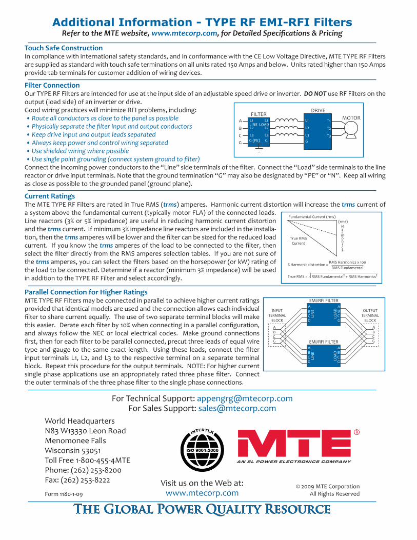
EMI/RFI FILTERABCG
ABCG
LIN
E
LOA
D
ABCG
ABCG
EMI/RFI FILTERABCG
ABCG
OUTPUTTERMINAL
BLOCK
LIN
E
LOA
DINPUTTERMINAL
BLOCK
Parallel Connection for Higher RatingsMTE TYPE RF Filters may be connected in parallel to achieve higher current ratings provided that identical models are used and the connection allows each individual filter to share current equally. The use of two separate terminal blocks will make this easier. Derate each filter by 10% when connecting in a parallel configuration, and always follow the NEC or local electrical codes. Make ground connections first, then for each filter to be parallel connected, precut three leads of equal wire type and gauge to the same exact length. Using these leads, connect the filter input terminals L1, L2, and L3 to the respective terminal on a separate terminal block. Repeat this procedure for the output terminals. NOTE: For higher current single phase applications use an appropriately rated three phase filter. Connect the outer terminals of the three phase filter to the single phase connections.
Filter ConnectionOur TYPE RF Filters are intended for use at the input side of an adjustable speed drive or inverter. DO NOT use RF Filters on the output (load side) of an inverter or drive.Good wiring practices will minimize RFI problems, including: • Route all conductors as close to the panel as possible • Physically separate the filter input and output conductors • Keep drive input and output leads separated • Always keep power and control wiring separated • Use shielded wiring where possible • Use single point grounding (connect system ground to filter)Connect the incoming power conductors to the “Line” side terminals of the filter. Connect the “Load” side terminals to the line reactor or drive input terminals. Note that the ground termination “G” may also be designated by “PE” or “N”. Keep all wiring as close as possible to the grounded panel (ground plane).
FILTERDRIVE
A
B
CG
L1
L2
L3G
T1
T2
T3
L1
L2
L3G
L1
L2
L3G (PE)
LINE LOAD
MOTOR
Current RatingsThe MTE TYPE RF Filters are rated in True RMS (trms) amperes. Harmonic current distortion will increase the trms current of a system above the fundamental current (typically motor FLA) of the connected loads. Line reactors (3% or 5% impedance) are useful in reducing harmonic current distortion and the trms current. If minimum 3% impedance line reactors are included in the installa-tion, then the trms amperes will be lower and the filter can be sized for the reduced load current. If you know the trms amperes of the load to be connected to the filter, then select the filter directly from the RMS amperes selection tables. If you are not sure of the trms amperes, you can select the filters based on the horsepower (or kW) rating of the load to be connected. Determine if a reactor (minimum 3% impedance) will be used in addition to the TYPE RF Filter and select accordingly.
Fundamental Current (rms)(rms)
Harmonics
True RMSCurrent
True RMS = RMS Fundamental² + RMS Harmonics²
RMS Harmonics x 100RMS Fundamental
% Harmonic distortion =
Additional Information - TYPE RF EMI-RFI FiltersRefer to the MTE website, www.mtecorp.com, for Detailed Specifications & Pricing