type w3 compass control - wascomat.net · type w3... compass control installation manual. before...
TRANSCRIPT

Wascomat provides efficient washers, dryers, flatwork ironers and wetcleaning systems in a size and model for every laundry and wetcleaning need!
516-371-4400
DOC. NO. 438.9037-39/10 EDITION 2011.08.22
EX618co – EX675co, SU620cc/co – SU677cc/co,
W620cc – W677cc Type W3...
Compass Control
InstallatIon manual

Before ordering parts, refer to the Wascomat spare parts manual (also available on www.wascomat.com) to determine the part number(s) for the item(s) you need.
For quick service, please have the following information available:
1. Part Number of the item(s) you need.2. Model of the machine.3. Serial number of the machine.4. Electrical data for the machine: – 120 or 208-240 Volt? – Single or three phase? – 50 or 60 Cycle?
To insure parts order accuracy, only fax or emailparts orders are accepted:
– Fax: 516-371-4029 – email: [email protected]
For service information, first contact your local authorized Wascomat dealer.
Wascomat technical support can assist you or your technician to diagnose and repair your laundry machines over the phone. Please call from the location where the machines are installed (we suggest you use a cellular or cordless phone), and have the following information available:
1. Model of the machine.2. Serial number of the machine.3. Electrical data for the machine: – 120 or 208-240 Volt? – Single or three phase? – 50 or 60 Cycle?4. An accurate description of the malfunction.
Wascomat customer supportWhether you need spare parts or technical advice to guide you to the source of a
malfunction, our nationwide network of authorized dealers are able and ready to serve your needs, or call the Wascomat Customer service Hotlines listed below.
For PArTS, SErViCE ANd TEChNiCAl ASSiSTANCE CAll your loCAl WASCoMAT dEAlEr
spare parts technical support
Warranty claimsWascomat’s technical support staff will honor valid manufacturer’s parts warranty claims providing your Wascomat
machines are registered for warranty coverage upon installation. If they are not registered, you can validate your warranty claim by providing information about when and where you purchased the Wascomat machine(s), the model and
serial number(s). additional warranty proof may also be required.
461 Doughty Blvd., Inwood, n.Y. 11096-0338 | sales and administration – tel: 516-371-4400 • Fax: 516-371-4204 • e-mail: [email protected]
spare Parts – tel: 516-371-2000 • Fax: 516-371-4029 • e-mail: [email protected] | technical support – tel: 516-371-0700 • Fax: 516-371-4029
En mexico: llame gratis a este numero 001-800-010-1010
516-371-2000 516-371-0700
to expedite parts order shipment, please use your credit card.We accept: american Express, mastercard, Visa, Discover, Diner’s Club.
3Safety
WARNING: ALL OPERATING AND MAINTENANCE PROCEDURES SHOWN ON THE NEXT PAGE OF THIS MANUAL MUST BE FOLLOWED DAILY FOR PROPER OPERATION OF YOUR MACHINE.
PLEASE ENTER THE FOLLOWING INFORMATION AS IT APPEARS ON THE MACHINE(S) DATA PLATE(S).
MAKE CERTAIN TO KEEP THIS MANUAL IN A SECURE PLACE FOR FUTURE REFERENCE.
MACHINE TYPE OR MODEL
MACHINE SERIAL NUMBER(S)
ELECTRICAL CHARACTERISTICS: _________ VOLTS, ________ PHASE, ________ HZ.
SAFETY AND WARNINGS SIGNSReplace If Missing Or Illegible
One or more of these signs must be affixed on each machine as indica-ted, when not included as part of the front instruction panel.
LOCATED ON THE OPERATING INSTRUCTION SIGN OF THE MACHINE:
CAUTION1. Do not attempt to open door unitl "Door unlocked" indicator is lit.
2. Machine must not be used by children.
3. Do not use flammable liquids in this machine.
MACHINE MUST NOT BE USED BY CHILDREN
ATTENTION1. Ne pas tenter d'ouvrir la porte avant que l'indicateur « Porte déverrouillée » ne soit allumé.
2. La machine ne doit pas être utilisée par des enfants.
3. Ne pas utiliser de liquides inflammables dans cette machine.
LA MACHINE NE DOIT PAS ÊTRE UTILISÉE PAR DES ENFANTS
PRECAUCION1. No intente abrir la puerta hasta que la luz indicadora este encendida.
2. La maquina no debe ser operado por ninos.
3. No use liquidos inflamable en la lavadora.
LAS MÁQUINAS NO DEBEN SER USADAS POR NIÑOS
FR
ES
4
IMPORTANT SAFETY INSTRUCTIONS
IMPORTANTES MESURES DE SECURITE
WARNING -
To reduce the risk of fire, electric shock, or injury to persons when using your appliance, including the following:
AVERTISSEMENT -
Pour réduire les risques d’incendie, de choc électrique ou de blessure quand, l’appareil est utilisé, prendre les précautions élémentaires et :
1. Read all instructions before using the appliance.
Lire toutes les instructions avant d’utiliser l’appareil.
2. This machine must be securely bolted to an uncovered concrete floor.
Cette machine doit être solidement fixée sur un sol en béton sans revêtement.
3. This machine MUST be serviced and operated in compliance with manufacturers instructions.
CHECK DOOR LOCKS EVERY DAY FOR PROPER OPERATION TO PREVENT INJURY OR DAMAGE.
IF THE DOOR LOCK FAILS TO OPERATE PROPERLY, PLACE THE MACHINE OUT OF ORDER UNTIL THE PROBLEM IS CORRECTED.
IL FAUT QUE cette appareil soit entretenue et actionnée conformement aux instructions du fabriquant.
CONTROLEZ LA SERRURE DE PORTE TOUS LES JOURS AFIN DE EVITER DES DOMMAGES OU DES RIS-QUES PERSONNELLES, SI LA SERRURE DE PORTE NE FONCTIONNE PAS, IL FAUT METTRE LA MACHINE HORS SERVICE JUSQU’Á LE PROBLEME SOIT CORRIGÉ.
4. Do not wash articles that have been previously cleaned in, washed in, soaked in, or spotted with gasoline, drycleaning solvents, or other flammable or explosive substances, as they give off vapors that could ignite or explode.
Ne pas laver des articles qui ont été nettoyés ou lavés avec de I’essence, des solvants pour nettoyage à sec ou d’autres substances inflammables ou explosives, ou que I’on a fait tremper dans ces produits. Ces sub-stances dégagent des vapeurs qui peuvent s’enflammer ou exploser.
5. Do not add gasoline, dry-cleaning solvents, or other flammable or explosive substances to the wash water. These substances give off vapours that could ignite or explode.
Ne pas ajouter d’essence, de solvants pour nettoyage à sec ou d’autres substances inflammables ou explosi-ves à I’eau de lavage. Ces substances dégagent des vapeurs qui peuvent s’enflammer ou exploser.
6. Under certain conditions, hydrogen gas may be produced in a hot-water system that has not been used for 2 weeks or more. HYDROGEN GAS IS EXPLOSIVE. If the hot-water system has not been used for such a period, before using a washing machine, turn on all hot-water faucets and let the water flow from each for several minutes. This will release any accumulated hydrogen gas. As the gas is flammable, do not smoke or use an open flame during thes time.
De I’hydrogène peut étre produit dans un système à eau chaude qui n’a pas été utilisé depuis deux semai-nes ou plus. L’HYDROGÈNE EST EXPLOSIF. Si le système à eau chaude n’a pas été utilisé depuis un cer-tain temps, ouvrir tous les robinets d’eau chaude et laisser I’eau couler pendant plusieurs minutes avant d’utiliser une laveuse, I’hydrogène accumulé, le cas échéant, s’échappera. L’hydrogène étant inflammable, ne pas fumer ou utiliser un appareil à flamme nue pendant que I’eau coule.
7. Do not allow children to play on or in the appliance. Close supervision of children is necessary when the app-liance is used near children.
Ne pas permettre aux enfants de jouer sur ou dans I’appareil. Surveiller ètriotement les enfants lorsqu’ils se trouvent prés de I’appareil qui fonctionne.
8. Before the appliance is removed from service or discarded, remove the door.
Avant de mettre I’appareil hors service ou de jeter, retirer la porte.
9. Do not reach into the appliance if the tub is moving.
Ne pas mettre la main dans I’appareil lorsque la cuve bougent.
Safety
5Safety
10. Do not install or store this appliance where it will be exposed to the weather. Ne pas installer ou placer cet appareil dans un endroit où il sera exposé aux intempéries.
11. Do not tamper with controls.
Ne pas trafiquer les commandes.
12. Do not repair or replace any part of the appliance or attempt any servicing unless specifically recommended in the user-maintenance instructions or in published user-repair instructions that you understand and have the skills to carry out.
Ne pas réparer ou remplacer les pièces de I’appareil ou procéder à I’entretien de celui-ci sauf si les instruc-tions visant I’entretien et les réparations qui doivent étre effectués par I’utilisateur le spécifient, si vous comprenez bien ces instructions et si vous possédez les connaissances nécessaires.
13. Changing of fuses inside the washing machine may only be carried out by authorized personnel.
14. This machine MUST be connected to a dedicated electrical circuit to which no other lighting unit or general purpose receptacle is connected. Use copper conductior only.
Utiliser seulement des conducteurs en cuivre.
6 Safety
NOTICE TO: OWNERS, OPERATORS AND DEALERS
IMPROPER INSTALLATION AND INADEQUATE MAINTENANCE, POOR HOUSEKEEPING AND WILL FUL NEGLECT OR BYPASSING OF SAFETY DEVICES MAY RESULT IN SERIOUS ACCIDENTS OR INJURY. TO ASSURE THE SAFETY OF CUSTOMERS AND/OR OPE RATORS OF YOUR MACHINE, THE FOLLOWING MAINTENANCE CHECKS MUST BE PERFORMED ON A DAILY BASIS.
FR NOTICE À L’ATTENTION DES PROPRIÉTAIRES, UTILISATEURS ET REVENDEURS DE MACHINES
UNE INSTALLATION INCORRECTE ET UN ENTRETIEN INADÉQUAT, DE MÊME QUE LA NÉGLIGENCE OU LA NEUTRALISATION DÉLIBÉRÉES DES DISPOSITIFS DE SÉCURITÉ, PEUVENT ÊTRE CAUSES DE BLESSURES OU D’ACCIDENTS SÉRIEUX. POUR ASSURER LA SÉCURITÉ DES CLIENTS ET/OU DES UTILISATEURS DE VOTRE MACHINE, IL EST INDISPENSABLE DE PROCÉDER CHAQUE JOUR AUX CONTRÔLES DE ROUTINE CI-APRÈS.
ES AVISO PARA LOS PROPIETARIOS, USUARIOS Y REVENDEDORES DE LAS MÁQUINAS UNA MALA INSTALACIÓN Y UN MANTENIMIENTO POCO ADECUADO, ASÍ COMO UNA NEGLIGENCIA O
NEUTRALIZACIÓN DELIBERADA DE LOS DISPOSITIVOS DE SEGURIDAD PUEDEN CAUSAR LESIONES U ACCIDENTES GRAVES. PARA GARANTIZAR LA SEGURIDAD DE LOS CLIENTES Y/O USUARIOS DE SU MÁ-QUINA, RESULTA INDISPENSABLE EFECTUAR A DIARIO LAS SIGUIENTES COMPROBACIONES RUTINARIAS
1. Prior to operation of the machine, check to make certain that all operating instructions and warning signs are affixed to the machine and legible. Missing or illegible ones must be replaced immediately. Be sure you have spare signs and labels available at all times. These can be obtained from your dealer.
2. Check the door safety interlock, as follows:
(a) OPEN THE DOOR of the machine and attempt to start in the normal manner:
For coin-operated models, insert the proper coins to start the machine.
For manually operated models, place the ON-OFF switch in the ON position and press the Start switch.
THE MACHINE(S) MUST NOT START !
(b) CLOSE THE DOOR to start machine operation and, while it is operating, attempt to open the door without exerting extreme force on the door handle. The door should remain locked!
If the machine can start with the door open, or can continue to operate with the door unlocked, the door interlock is no longer operating properly. The machine must be placed out of order and the interlock immediately replaced. (See the door interlock section of the manual.)
3. DO NOT UNDER ANY CIRCUMSTANCES ATTEMPT TO BYPASS OR REWIRE ANY OF THE MACHI-NE SAFETY DEVICES AS THIS CAN RESULT IN SERIOUS ACCIDENTS.
4. Be sure to keep the machine(s) in proper working order: Follow all maintenance and safety pro-cedures. Further information regarding machine safety, service and parts can be obtained from your dealer.
All requests for assistance must include the model, serial number and electrical characteristics as they appear on the machine identification plate. Insert this information in the space provided on the previous page of this manual.
5. WARNING: DO NOT OPERATE MACHINE(S) WITH SAFETY DEVICES BYPASSED, REWIRED OR INOPERA-TIVE! DO NOT OPEN MACHINE DOOR UNTIL DRUM HAS STOPPED ROTATING!
FR AVERTISSEMENT: NE PAS FAIRE FONCTIONNER LA (LES) MACHINE(S) AVEC UN DISPOSITIF DE SÉCURITÉ NEUTRALISÉ, RECÂBLÉ OU NON OPÉRATIONNEL! NE PAS OUVRIR LA MACHINE TANT QUE LE TAMBOUR NE S’EST PAS IMMOBILISÉ!
ES ADVERTENCIA: NO USAR NINGUNA MÁQUINA SI SE HA NEUTRALIZADO EL DISPOSITIVO DE SEGURIDAD, SE HAN CAMBIADO LOS CABLES O SI NO FUNCIONA CORRECTAMENTE. NO ABRIR LA MÁQUINA HASTA QUE EL TAMBOR SE HAYA DETENIDO POR COMPLETO.

7
NOTICE TO INSTALLER
Improper installation of this machine:
•Maycauseseriousdamagetothemachine.•Mayresultinotherpropertydamage.•Maycausepersonalinjury.•Willvoidthemanufacturer'swarranty.
Improper fastening of this machine to its foundation, inferior foundation materials, an undersized founda-tion, the use of fabricated steel bases not provided by Wascomat or its approved supplier(s), the use of an improper type, number, or size of mounting bolts, or failure to use proper hardware on mounting bolts may result in damage to the machine that will not be covered by the manufacturer's warranty.
Use of a steel base beneath this machine DRAMATICALLY INCREASES the mechanical stress placed on the underlying concrete floor or foundation. This must be taken into consideration when employing a steel base to raise the height of the machine.
Increase the manufacturer's recommended floor or foundation thickness requirements by at least three inches (see installation manual) when using six-inch-high Wascomat steel bases to raise the machine's height.
The use of steel bases more than six inches in height is NOT recommended. If installation requires a base higher than six inches, contact Wascomat Technical Support at 516-371-0700 for advice.
Connection to line Voltage or over-current protection devices other than those specified on the data plate may result in severe damage to machine components, and will void the manufacturer's warranty.
Refer to complete installation instructions provided in manuals accompanying the machine.
Contact Wascomat Technical Support at 516-371-0700 with any questions BEFORE installing this machine. Damage resulting from inadequate installation materials or improper installation techni-ques will void the manufacturer's warranty.
Safety

9Contents
Contents
Safety precautions .................................................................................... 11Technical data ............................................................................................ 13Installation .................................................................................................. 21 Transportation and unpacking ............................................................. 21 Siting and floor ...................................................................................... 23 Mechanical installation .......................................................................... 24Installation W- and SU-model .................................................................... 25 Siting ..................................................................................................... 25 Floor ...................................................................................................... 25 Casting a plinth...................................................................................... 27 Installing the machine ............................................................................ 28 Water connections ................................................................................ 29 Drain connection ................................................................................... 31 Steam connection ................................................................................. 32 Connection of external liquid supplies .................................................. 33 Functions for I/O-cards ......................................................................... 36 Electrical installations ............................................................................ 44Function checks ......................................................................................... 51
The manufacturer reserves the right to make changes to design and com ponent specifications.


11Safety Precautions
All external equipment which is connected to the machine must be CE/EMC-approved and connected using an approved shielded cable.
Safety Precautions
The machine is only intended for water-wash use.
Do not allow minors to use the machine.
Do not hose down the machine with water.
The machine's door lock must under no circumstances be bypassed.
If the machine develops a fault, this must be reported to the person in charge as soon as possible. This is important both for your safety and that of others.
The machine is not intended to be used by people (including minors) with reduced physical or mental capacity or lack of experience and knowledge. Such people must be instructed in the use of the machine by a person who has responsibility for their safety. Minors must be supervised to ensure that they do not play with the machine.
In order to prevent damage to the electronics (and other parts) that may occur as the result of condensation, the machine should be placed in room temperature for 24 hours before being used for the first time.

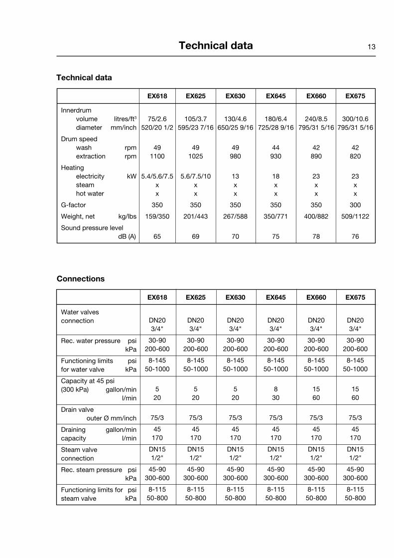
13Technical data
EX618 EX625 EX630 EX645 EX660 EX675
75/2.6 105/3.7 130/4.6 180/6.4 240/8.5 300/10.6 520/20 1/2 595/23 7/16 650/25 9/16 725/28 9/16 795/31 5/16 795/31 5/16
49 49 49 44 42 42 1100 1025 980 930 890 820
5.4/5.6/7.5 5.6/7.5/10 13 18 23 23 x x x x x x x x x x x x
350 350 350 350 350 300
159/350 201/443 267/588 350/771 400/882 509/1122
65 69 70 75 78 76
Connections
Technical data
Innerdrum volume litres/ft3 diameter mm/inch
Drum speed wash rpm extraction rpm
Heating electricity kW steam hot water
G-factor
Weight, net kg/lbs
Sound pressure level dB (A)
EX618 EX625 EX630 EX645 EX660 EX675
DN20 DN20 DN20 DN20 DN20 DN20 3/4" 3/4" 3/4" 3/4" 3/4" 3/4"
30-90 30-90 30-90 30-90 30-90 30-90 200-600 200-600 200-600 200-600 200-600 200-600
8-145 8-145 8-145 8-145 8-145 8-145 50-1000 50-1000 50-1000 50-1000 50-1000 50-1000
5 5 5 8 15 15 20 20 20 30 60 60
75/3 75/3 75/3 75/3 75/3 75/3
45 45 45 45 45 45 170 170 170 170 170 170
DN15 DN15 DN15 DN15 DN15 DN15 1/2" 1/2" 1/2" 1/2" 1/2" 1/2"
45-90 45-90 45-90 45-90 45-90 45-90 300-600 300-600 300-600 300-600 300-600 300-600
8-115 8-115 8-115 8-115 8-115 8-115 50-800 50-800 50-800 50-800 50-800 50-800
Water valves connection
Rec. water pressure psi kPa
Functioning limits psi for water valve kPa
Capacity at 45 psi (300 kPa) gallon/min l/min
Drain valve outer Ø mm/inch
Draining gallon/min capacity l/min
Steam valve connection
Rec. steam pressure psi kPa
Functioning limits for psi steam valve kPa
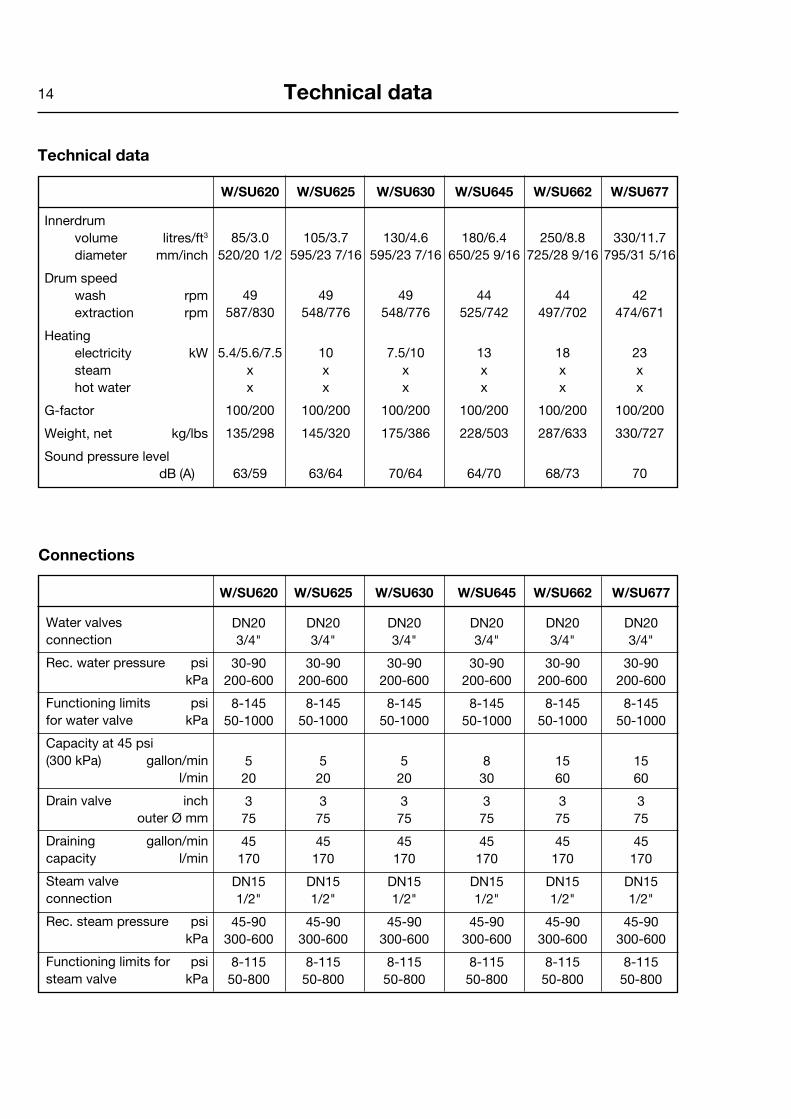
14 Technical data
W/SU620 W/SU625 W/SU630 W/SU645 W/SU662 W/SU677
85/3.0 105/3.7 130/4.6 180/6.4 250/8.8 330/11.7 520/20 1/2 595/23 7/16 595/23 7/16 650/25 9/16 725/28 9/16 795/31 5/16
49 49 49 44 44 42 587/830 548/776 548/776 525/742 497/702 474/671
5.4/5.6/7.5 10 7.5/10 13 18 23 x x x x x x x x x x x x
100/200 100/200 100/200 100/200 100/200 100/200
135/298 145/320 175/386 228/503 287/633 330/727
63/59 63/64 70/64 64/70 68/73 70
W/SU620 W/SU625 W/SU630 W/SU645 W/SU662 W/SU677
DN20 DN20 DN20 DN20 DN20 DN20 3/4" 3/4" 3/4" 3/4" 3/4" 3/4"
30-90 30-90 30-90 30-90 30-90 30-90 200-600 200-600 200-600 200-600 200-600 200-600
8-145 8-145 8-145 8-145 8-145 8-145 50-1000 50-1000 50-1000 50-1000 50-1000 50-1000
5 5 5 8 15 15 20 20 20 30 60 60
3 3 3 3 3 3 75 75 75 75 75 75
45 45 45 45 45 45 170 170 170 170 170 170
DN15 DN15 DN15 DN15 DN15 DN15 1/2" 1/2" 1/2" 1/2" 1/2" 1/2"
45-90 45-90 45-90 45-90 45-90 45-90 300-600 300-600 300-600 300-600 300-600 300-600
8-115 8-115 8-115 8-115 8-115 8-115 50-800 50-800 50-800 50-800 50-800 50-800
Water valves connection
Rec. water pressure psi kPa
Functioning limits psi for water valve kPa
Capacity at 45 psi (300 kPa) gallon/min l/min
Drain valve inch outer Ø mm
Draining gallon/min capacity l/min
Steam valve connection
Rec. steam pressure psi kPa
Functioning limits for psi steam valve kPa
Connections
Technical data
Innerdrum volume litres/ft3 diameter mm/inch
Drum speed wash rpm extraction rpm
Heating electricity kW steam hot water
G-factor
Weight, net kg/lbs
Sound pressure level dB (A)

15Technical data
A B C D E F G H I K L M N O P R S
EX618 720 690 1115 355 720 825 45 1030 220 1010 135 910 830 360 100 240 –
EX625 830 705 1200 365 740 910 45 1115 220 1095 135 995 910 415 100 295 –
EX630 910 785 1325 435 825 1035 125 1245 215 1225 300 1125 – – 100 305 455
EX645 970 870 1410 470 945 1120 115 1330 230 1290 315 1205 370 410 100 335 485
EX660 1020 915 1445 500 955 1155 100 1360 215 1320 300 1240 350 360 100 360 510
EX675 1020 1060 1445 500 1135 1155 100 1360 215 1320 300 380 – – 100 360 330
EX618, EX625, EX630
EX645, EX660, EX675
Rear sideFront Right side
Rear sideFront Right side
1 Electrical connection 2 Cold water 3 Hot water 4 Hard water (option) 5 Steam connection 6 Drain 7 Liquid detergent supply 8 Control panel 9 Soap box 10 Door opening, EX618: ø 310 mm/12 3/16", EX625: ø 365 mm/14 3/8", EX630: ø 395 mm/15 9/16", EX645, EX660, EX675: ø 435 mm/17 1/8"
A
89
10
C
D
5281 B
B
E
6
5282 B
K
NM
R
P
6
F
5
1
O
G
I
L
3
2
74
5283 B
A9
10
8
D
C
5377 A5379 A
B
E
6
G
S L
M
I
5
1
F
6
P
R
KH
5378 A
7
3
22

16 Technical data
EX618, EX625, EX630
EX645, EX660, EX675
in inch A B C D E F G H I K
EX618 28 3/8 27 3/16 43 7/8 14 28 3/8 32 1/2 1 3/4 40 9/16 8 11/16 39 3/4
EX625 32 11/16 27 3/4 47 1/4 14 3/8 29 1/8 35 13/16 1 3/4 43 7/8 8 11/16 43 5/16
EX630 35 13/16 30 7/8 52 3/16 17 1/8 32 1/2 40 3/4 4 15/16 49 8 7/16 48 1/4
EX645 38 3/16 34 1/4 55 1/2 18 1/2 37 3/16 44 1/8 4 1/2 52 3/8 9 1/16 50 13/16
EX660 40 3/16 36 56 7/8 19 11/16 37 5/8 45 1/2 3 15/16 53 9/16 8 7/16 51 15/16
EX675 40 3/16 41 3/4 56 7/8 19 11/16 44 11/16 45 1/2 3 5/16 53 9/16 8 7/16 51 15/16
in inch L M N O P R S
EX618 5 5/16 35 13/16 32 11/16 14 3/16 3 5/16 9 7/16 –
EX625 5 5/16 39 3/16 35 13/16 16 5/16 3 5/16 11 5/8 –
EX630 11 13/16 44 5/16 – – 3 5/16 12 17 15/16
EX645 12 3/8 47 7/16 14 9/16 16 1/8 3 5/16 13 3/16 19 1/8
EX660 11 13/16 48 13/16 13 3/4 14 15/16 3 5/16 14 3/16 20 1/16
EX675 12 3/16 14 15/16 – – 3 15/16 14 3/16 13
Rear sideFront Right side
Rear sideFront Right side
A
89
10
C
D
5281 B
B
E
6
5282 B
K
NM
R
P
6
F
5
1
O
G
I
L
3
2
74
5283 B
A9
10
8
D
C
5377 A5379 A
B
E
6
G
S L
M
I
5
1
F
6
P
R
KH
5378 A
7
3
22

17Technical data
1 Electrical connection 2 Cold water 3 Hot water 4 Steam connection 5 Drain 6 Liquid detergent supply 7 Control panel 8 Soap box 9 Water reuse 10 Door opening, W/SU620: ø 310 mm/12 3/16", W/SU625, SU630: ø 365 mm/14 3/8", W630, SU645: ø 395 mm/15 9/16", W645, W/SU662, W/SU677: ø 435 mm/17 1/8"
W/SU620-630
Rear side
Right sideFront Rear side
W/SU645-677
in mm A B C D E F G H I K L M N O P R
W/SU620 660 730 1115 355 765 825 45 1030 215 1010 130 830 385 – 100 225
W/SU625 720 705 1200 365 740 910 45 1115 215 1095 130 910 420 – 100 235
W/SU630 720 790 1200 365 825 910 45 1115 215 1095 130 910 420 – 100 235
W645 750 880 1333 435 915 1035 45 1245 130 1225 210 1040 325 295 100 225
SU645 750 880 1333 435 915 1035 45 1245 130 1225 210 1040 325 295 100 225
W662 830 955 1410 470 990 1120 45 1330 160 1290 245 1125 325 325 100 265
SU662 830 955 1410 470 990 1120 45 1330 160 1290 245 1125 325 325 100 265
W677 910 1040 1445 500 1075 1155 45 1365 160 1325 245 1155 280 325 100 210
8 7
C
D
A
10
5281
B
E
5
5282
N
G
I
F
L
R
P
H
MK
5
4
1
3
2
6
5283
9
M
P
F
K
I
L
G
R
H
O
N
4
1
5
3
2 9
6
5459

18
W/SU620-630
Rear side
Right sideFront Rear side
W/SU645-677
Technical data
in inch A B C D E F G H I K
W/SU620 26 28 3/4 43 7/8 14 30 1/8 32 1/2 1 3/4 40 9/16 8 7/16 39 3/4
W/SU625 28 3/8 27 3/4 47 1/4 14 3/8 29 1/8 35 13/16 1 3/4 40 7/8 8 7/16 43 1/8
W/SU630 28 3/8 31 1/8 47 1/4 14 3/8 32 1/2 35 13/16 1 3/4 40 7/8 8 7/16 43 1/8
W645 29 1/2 34 5/8 52 1/2 17 1/8 36 40 3/4 1 3/4 49 5 1/8 48 1/4
SU645 29 1/2 32 11/16 52 1/2 14 3/8 36 40 3/4 1 3/4 49 5 1/8 48 1/4
W662 32 11/16 37 5/8 55 1/2 19 1/2 39 44 1/8 1 3/4 52 3/8 6 5/16 50 13/16
SU662 32 11/16 37 5/8 55 1/2 17 1/8 39 44 1/8 1 3/4 52 3/8 6 5/16 50 13/16
W677 35 13/16 40 15/16 56 7/8 19 11/16 42 5/16 45 1/2 1 3/4 53 3/4 6 5/16 52 3/16
in inch L M N O P R
W/SU620 5 1/8 32 11/16 15 3/16 – 3 15/16 8 7/8
W/SU625 5 1/8 35 13/16 19 9/16 – 3 15/16 9 1/4
W/SU630 5 1/8 35 13/16 16 9/16 – 3 15/16 9 1/4
W645 8 1/4 40 15/16 12 13/16 11 5/8 3 15/16 8 7/8
SU645 8 1/4 40 15/16 12 13/16 11 5/8 3 15/16 8 7/8
W662 9 5/8 44 5/16 12 13/16 12 13/16 3 15/16 10 7/16
SU662 9 5/8 44 5/16 12 13/16 12 13/16 3 15/16 10 7/16
W677 9 5/8 45 1/2 11 12 13/16 3 15/16 8 1/4
8 7
C
D
A
10
5281
B
E
5
5282
N
G
I
F
L
R
P
H
MK
5
4
1
3
2
6
5283
9
M
P
F
K
I
L
G
R
H
O
N
4
1
5
3
2 9
6
5459

19Technical data
EX618 EX625 EX630 EX645 EX660 EX675
18.3 17.1 16.3 15.5 14.8 13.7
417±110 560±112 703±114 944±221 1158±221 1387±292 1.9±0.5 2.5±0.5 3.1±0.5 4.2±1.0 5.2±1.0 6.2±1.3
Frequency of the dynamic force Hz
Floor load at lbs forcemax extraction kN
Frequency of the dynamic force Hz
Floor load at lbs forcemax extraction kN
9.3/13.8 9.1/12.9 9.1/12.9 8.8/12.4 8.3/11.7 7.9/11.2
382±697/ 427±562/ 540±697/ 652±877/ 854±1102/ 1034±1259/ 382±585 427±674 517±854 674±1079 854±1326 967±1551
1.7 ± 3.1/ 1.9 ± 2.5/ 2.4 ± 3.1/ 2.9 ± 3.9/ 3.8 ± 4.9/ 4.6 ± 5.6/ 1.7 ± 2.6 1.9 ± 3.0 2.3 ± 3.8 3.0 ± 4.8 3.8 ± 5.9 4.3 ± 6.9
W620/ W625/ W630/ W645/ W662/ W677/ SU620 SU625 SU630 SU645 SU662 SU677


21Installation
5325
1
5326
2
Installation
Transportation and unpacking, EX618, EX625
The machine is delivered complete with expan-der bolts etc. packed inside the machine in the drum.
The machine is delivered bolted onto the trans-port pallet and packed in a crate or box.
• Removepackingfromthemachine.
• Removefrontandrearpanel.Removethe bolts between the machine and pallet.
• Mountfrontandrearpanel.
• Mountthefeet.
• Placethemachineonitsfinalposition.
• Levelthemachinewiththefeetofthe machine.
The machine also comes with transport safety devices (four plate angles between the frame and the drum).
In order to remove the safety devices:
• Unpackthemachine.
• Removefrontandrearpanel.
• Removebothfrontmetalangels.
• Removebothrearmetalangels.
NOTE! Once the shipping safety devices have been removed, handle the machine carefully to avoid damage to the suspension components.
1
2

22
5340
3
6445
4
5341
5
Transportation and unpacking, EX630, EX645, EX660, EX675
The machine is delivered complete with expan-der bolts etc. packed inside the machine in the drum.
The machine is delivered bolted onto the trans-port pallet and packed in a crate or box.
• Removepackingfromthemachine.
• Removefrontandrearpanel.Removethe bolts between the machine and pallet.
• Mountfrontandrearpanel.
• Mountthefeet.
NOTE!Regarding EX675 note the positioning of the two front feet.
• Placethemachineonitsfinalposition.
• Levelthemachinewiththefeetofthe machine.
Themachinealsocomeswithtransportsafetydevices(twoplateanglesbetweenthesupportand the drum).
Inordertoremovethesafetydevices:
• Unpackthemachine.
• Removethetwosidepanels.
• Removethetwotransportsecurities.
NOTE! Once the shipping safety devices have been removed, handle the machine carefully to av-oid damage to the suspension components.
3
5
4
Installation
23Installation
5327
6
2"20"
50 mm500 mm
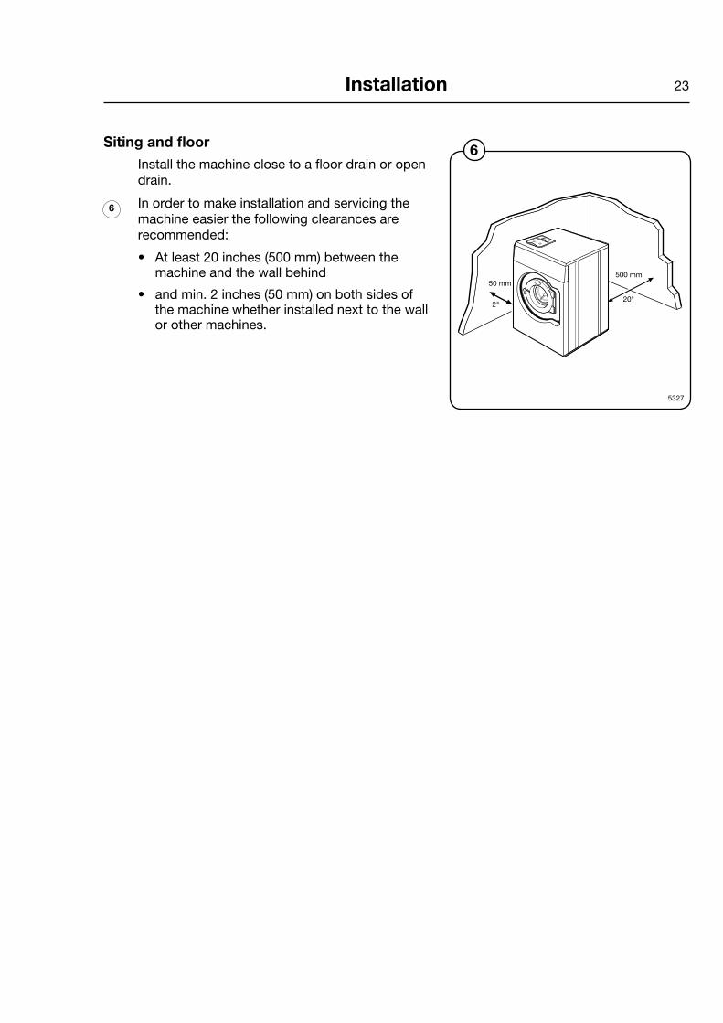
Siting and floor
Install the machine close to a floor drain or open drain.
In order to make installation and servicing the ma chine easier the following clearances are recommended:
• Atleast20inches(500mm)betweenthemachine and the wall behind
• andmin.2inches(50mm)onbothsidesofthe machine whether installed next to the wall or other machines.
6

24 Installation
C A
D
G
F E
B
HFRONT
5358
7Mechanical installation
• Markanddrill2holes(ø8mm/5/16")about40mm/19/16"deep(EX618-625)andø10mm/3/8"and50mm/2"deep(EX630-660)inthepositions.
=positionoffeet
=drillingpointsforexpanderbolts
• Themachinemustbeliftedinitsbaseframe.
• Placethemachineoverthetwodrilledholesonthefoundation.
• Checkthatthemachineisinlevel,bothside-to-sideandfronttoback.Adjustwiththefeet.
It is of utmost importance that the machine level, from side to side as well as front to rear. If the machine is not properly leveled, it may result in out-of-balance without a real out of balance in the drum.
• Mounttheexpanderboltsintheholesdril-ledinthefloor.Fitthewashersandnuts,andtightenwell.
7
ininch A B C D E F G H
EX618 191/2 181/8 45/16 51/8 143/4 611/16 19/16 315/16
EX625 225/8 185/16 51/8 51/2 1715/16 75/16 13/8 33/4
EX630 25 195/16 55/16 67/8 201/4 711/16 23/8 45/16
EX645 281/8 217/16 415/16 81/16 237/16 75/16 23/8 41/2
EX660 311/8 243/16 41/2 71/16 263/8 67/8 23/8 41/2
EX675 357/16 295/8 23/8 71/16 263/8 67/8 23/8 43/4
inmm A B C D E F G H
EX618 495 460 110 130 375 170 40 100
EX625 575 465 130 140 455 185 35 95
EX630 635 490 135 175 515 195 60 110
EX645 715 545 125 205 595 185 60 115
EX660 790 615 115 180 670 175 60 115
EX675 900 755 60 180 670 175 60 120

25Installation
8
5327
Installation W- and SU-modelLeave the machine on the tran s port pallet until it can be placed in the final, pre pared position.
Siting
Install the machine close to a floor drain or open drain. In order to make installation and servicing the machine easier the following clearances are recommended:
• Atleast20inches(500mm)betweenthemachine and the wall behind.
• Minimum1inch(25mm)tonextmachineifmore than one machine is installed on a foun-dation.
Floor
In this type of machine, the drum is attached di-rectly to the frame. As a result the floor under the machine must be stable enough to absorb the dy namic forces generated during spin cycles. For that reason, the mounting bolts must be cast into the floor material itself.
The machine must be securely fastened to a suitable foundation using M16 (5/8 inch) th-readed rod, flat washers and lock nuts or lock washers. Failure to properly secure the machine to its foundation, or securing the machine to an inadequate foundation, will result in severe vibra-tion, damage to the machine, and will void the manufacturer´s warranty.
When fixing the machine to an existing cement floor, it must be at least 8 inches (200 mm) thick.
The floor must be able to withstand the loads in-dicated in the table.
If it isn’t possible to cast the bolts into the floor, an alternative might be to use so-called chemical anchors. Your local dealer can provide the infor-ma tion you need.
IMPORTANT NOTE:The use of chemical anchors and/or the use of a fabricated steel mounting base DOES NOT re-duse the thickness requirement for the underly-ing concrete floor. The floor MUST BE AT LEAST 8 INCHES (200 MM) THICK, or a new concrete foundation MUST be poured.
8

26 Installation
in mm A B C D E F G H I
W620 725 660 495 445 115 665 – – –
W625 700 720 575 385 120 695 – – –
W630 785 720 575 495 120 760 – – –
W645 875 750 635 570 120 855 – – –
W662 950 830 715 635 125 955 – – –
W677 1035 910 790 695 135 1050 810 10 95
SU620 725 660 495 445 115 665 495 0 75
SU625 700 720 575 385 120 695 595 10 80
SU630 785 720 575 495 120 760 595 10 80
SU645 875 750 635 570 120 855 655 10 85
SU662 950 830 715 635 125 955 735 10 85
SU677 1035 910 790 695 135 1050 810 10 95
6099
9Model SU and W/E677
NOTE! For above models, two expander bolts must also be fitted to the front section of the mach-ine. If not, large vibrations in the machine cabinett may occur.
• Drilltwoholes(1)ø10mm/3/8"and40mm/ 19/16"deep.
• Afterthemachinehasbeenplacedovertheotherfourbolts,placethetwospacerwash-ersoverthetwoholes.Theyshallbeplacedbetweenthemachineandfoundation.
• Mounttheexpanderboltsinthedrilledholes.Fitthewashersandnuts,andtightenwell.
ininch A B C D E F G H I
W620 28 9/16 26 19 1/2 17 1/2 4 1/2 26 3/16 – – –
W625 27 7/8 28 3/8 22 3/4 15 3/16 4 3/4 27 13/32 – – –
W630 30 7/8 28 3/8 22 5/8 19 1/2 4 3/4 29 15/16 – – –
W645 34 7/16 29 1/2 25 22 7/16 4 3/4 33 11/16 – – –
W662 37 3/8 32 11/16 28 1/8 25 4 15/16 37 5/8 – – –
W677 40 3/4 35 13/16 31 1/8 27 3/8 5 5/16 41 5/16 31 7/8 13/32 3 3/4
SU620 28 9/16 26 19 1/2 17 1/2 4 1/2 26 3/16 19 1/2 0 2 15/16
SU625 27 7/8 28 3/8 22 3/4 15 3/16 4 3/4 27 13/32 23 7/16 13/32 3 1/8
SU630 30 7/8 28 3/8 22 5/8 19 1/2 4 3/4 29 15/16 23 7/16 13/32 3 1/8
SU645 34 7/16 29 1/2 25 22 7/16 4 3/4 33 11/16 25 13/16 13/32 3 3/8
SU662 37 3/8 32 11/16 28 1/8 25 4 15/16 37 5/8 28 15/16 13/32 3 3/8
SU677 40 3/4 35 13/16 31 1/8 27 3/8 5 5/16 41 5/16 31 7/8 13/32 3 3/4
9
B
A
CG
=1
=
EH
1
I
DF
27
150-200 mm
40 mm
125
Installation
5462
0899A
11
10Casting a plinth
A foundation should be used where the existing floor is less than 8 inches (200 mm) thick or in order to ensure that the machine is securely an-chored and will not vibrate excessively.
The foundation must be at least 8 inches (200 mm) thick.
Proceed as follows:
• Breakuptheexistingfloortoadepthofapprox.5inches(125mm)andcheckthatthesidesoftheholearetaperedoutwardsothatthe longest side at the bottom measures 5 inches(125mm)morethanatthetop.
• Maketheformsforthefoundation.
• Moistentheholewellandapplycementtothesides and bottom.
• Anumberofmountingboltsmustbeset into the concrete of the foundation. Theboltsneedtoproject111/2inches(40mm) out of the base. Pour the con crete into thepreparedbasemoldandmakesurethatthe surface is level.
• Theconcreteshouldbelefttosetforatleasttwo days before mounting the machine on the foundation.
• Mountingboltlocationsareshownwithrespecttotheoutersurfaceofthemachin'sfrontpanel.Ifthefrontpanelistobesetbackfrom the front of the foundation, add the set-back distance to dimension "E".
10
11

28 Installation
13
12
5463
5464
Installing the machine To install the machine:
• Removethetransportpackaging
• Removethefrontpanel.
• Removethemachinefromthetransportpalletand locate it on the bolts. Always lift the ma ch ine by the chassis, never by the door or door handle.
• Checkthatthemachineislevelandsteadyat all four corner mounting points. Adjust the level by using stain less or galvanized steel washers or shims be tween the machine and the floor. The wash ers must be of a size to cover the support sur face.
• Fitthewashersandself-lockingnutssuppliedwith the machine and tighten securely.
• Totightenthenutswerecommendtousea rachet wrench, especially in the right rear corner.
During the first several weeks of use, check and tighten the nuts (as necessary) frequently. Conti-nue to check them periodically, thereafter.
IMPORTANT NOTE:Failure to closely follow the instructions provided in this manual may result in severe damage to the machine, and the risk of personal injury. The manufacturer is not responsible for damage or injury resulting from improper installation.
12
13
14
5951, 5952
14

29Installation
Water connections
All inlet connections to the machine are to be fitted with manual shut-off valves and filters, to facilitate installation and servicing.
Water pipes and hoses should be flushed clean before installation. After installation, hoses should hang in gentle arcs.
Hoses are to be of an approved type and grade, to comply with national regulations.
The machine may have between one and four DN 20 (R 3/4") water con-nectors. All connectors present on the machine must be connected to the water supply, or the machine may not function properly. The table shows the possible connection options, which will depend on the model of the machine.
All water connectors must be connected up, otherwise the wash pro-gram will not function correctly.
The water pressure data is as follows:
• min: 15PSI(100kPa)
• max: 90PSI(600kPa)
• recommended: 30-90PSI(200-600kPa)

30 Installation
2
1
2 1
3
16
5339
15
5328
W/SU620, W/SU625 W/SU630, EX618, EX625, EX630
W/SU645, W/SU662, W/SU677, EX645, EX660 EX675
Water type Water connection
1 2 3
cold and hot cold hot
cold and hot cold hot cold*/ hot
* For detergent container.
Extra water valve which can be used for hard water if soft water is connected to 1.
This valve can also be used for water reuse from tank.
If pump is used, it is only a water connection without valve.
15
16

31Installation
5330
17
17
Drain connection Connect a 3 inch O.D. (75 mm) pipe or rubber
hose to the machine’s drain pipe, ensuring a downward flow from the machine. Avoid sharp bends which may prevent proper draining.
The washer may drain in to a drainage through or into a closed drain system. In either case, be sure to comply with all applicable national and local plumbing code provisions.

32 Installation
”HEAT”
A
B
18
6600
20
6601
19
5862
22
6604
21
6602
Steam connection
Inlet pipes connected to the machine must be equipped with a manual shut-off valve to facili-tate installation and servicing.
The connection hose must be of type ISO/1307-1983 or equivalent. Connection size at filter: DN 15 (BSP 1/2").
Steam pressure required:
• minimum:7psi(50kPa)
• maximum:115psi(800kPa)
• rec. pressure: 600 kPa (6 kp/cm2)
• Remove top cover (A).
• Remove casing (B).
• Mountthearticulatednippletothesteamvalve.
• Mountthesteamvalveonthemachine.
• Mountnipple,strainerandelbow.Notethedirection of the strainer. Mount steam hose to the elbow. Check that there are no sharp angles or bends on the connected steam hose.
• Mountthehosewithwiresbetweensteamvalve and machine. Connect wires in the steam valve. Connect ground cable to the terminal ground connection.
Connect the ”HEAT” cable connector to the ”HEAT” terminal on the I/O board.
18
19
20
21
22
33Installation
A
B
1 2
3
4
1
2
3
4
57
6
9
23
6598
6572
24
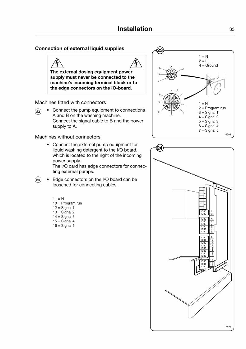
Connection of external liquid supplies
The external dosing equipment power supply must never be connected to the machine’s incoming terminal block or to the edge connectors on the IO-board.
Machines fitted with connectors
• ConnectthepumpequipmenttoconnectionsAandBonthewashingmachine. ConnectthesignalcabletoBandthepowersupplytoA.
Machineswithoutconnectors
• ConnecttheexternalpumpequipmentforliquidwashingdetergenttotheI/Oboard,whichislocatedtotherightoftheincomingpowersupply. TheI/Ocardhasedgeconnectorsforconnec-tingexternalpumps.
• EdgeconnectorsontheI/Oboardcanbeloosenedforconnectingcables.
23
24
1 = N 2 = L 4=Ground
1 = N 2=Programrun 3=Signal1 4=Signal2 5=Signal3 6=Signal4 7=Signal5
11 = N 18=Programrun 12=Signal1 13=Signal2 14=Signal3 15=Signal4 16=Signal5

34 Installation
��
������
���������������
������
26
6236
Outputs
• Connectexternalpowersupply(e.g.24VDC)for pumps to 9 and 10. If an internal power supply (from the washing machine) is being used, it can be taken from 1 (N) and connec-ted to 9 and from 2 (L) and connected to 10. Max load on the outputs 0.5 A.
• Signalsforpumps1-5areconnectedto12-16where connector 12 Washing detergent signal 1 13 Washing detergent signal 2 14 Washing detergent signal 3 15 Washing detergent signal 4 16 Washing detergent signal 5
Inputs
• Thesignallevelcanbe5-24VDC/ACor100-240VAC.For5-24V,thesignalreferenceisconnectedto3andfor100-240Vto4.Poten-tials on the inputs cannot be mixed. NB! The I/O board will be damaged if the vol-tageonconnection3istoohigh,>24V.
25
25
����
�������������
�
�
���
6634, 6635
26

35Installation
��������������
�����
��
�
�
�������������
�����������
�������������� �����
�
6265
29
28
6577
27
6266
24V
230V
• Connection 7. If this is connected, an error message will be displayed indicating that one of the chemical tanks is empty. The washing program will continue, however. The figure shows an example of engaging a normal open contact.
• Connect the liquid dosing hoses to any of the connections marked A.
28
29
• Connection8maybeconnectedifthewashingprogramistopause,e.g.whilewashingdetergent is being dosed. Thefigureshowsanexampleofengaginga24Vpausesignal. The washing program will pause for as long as the pause signal remains activated (high).
27
A
A

36 Installation
Functions for I/O -cards
The electrical schematic can have one of the following: 22A, 22B, 22C, 22D, 22E, 22F or 22G.
� �
�����
���
����
� �
����
����
������
��
� � �
�������
���
���
� � � � � �
���
���
���
� � � �
���
���
�� �
� �
�� �� ��
����������
�� �
� � � � � �
������
���
�����
����
�
�� �� ��
����
����
���
����
���
�����
����
�
� �� ��
������
���
��
� � �
���
���
����
����
����������������� ��
��������� ������ ���
�����
�
����
����
����
���
�� �������������������
����
���
� ��
����
���
���
����
���
���
������
�
�����
����
����
���������������������
���
���
������������������������������������������
������������������������������������������
����
���
���
�������������������� ����
�����
�
����
���
���
��������������
���
���
������������������������������������������
��������������������������������������������������� �������
� � � � �
6606
22A
• Thesignalreceivedfromexternalslotmetersmustbeapulse. In order to count down prices, the signal initiating the programming procedure must be active (high).

37Installation
�����
����
�����
����
�����
�
���������������
���
�����
����
�
��������������
����
����
����
�
���������
��������
���
���
���
���������
��������
��
��������������������
�����������
���������������
���������������
����
����
���
��
���
��
��
��
�����
��
����
�
���
���� �������
���
����
����
����
������
��
����
�
���
���
���
���
��
���
�����
����
�
����
�����
����
���
�
���
����
����
���
���
� � � � � � �
� � � � � �
������
����
� �
� ��
�������
���
����
����
�
����
�
����
�
����
�
����
�
� � � � �
�� �� �� �� �� �
���
���
� � �
� �� ��
������
���
����
��
�����
����
����
�
����
�
����
�
����
�
����
�
�����������������������
��������������
�
��
���
���
22B
6316
• Tostartthemachinefromacentralpaymentsystem,thepaymentsystemmust transmit a start pulse to the machine. Door lock activates on positive flank and program starts on negative flank of start pulse. The start pulse can beeither230Vor24V.Inordertoreceiveafeedbacksignaloncethemachinehasstarted,230Vor24Vmustbeconnectedtoconnection19.Thefeedbacksignal on connection 18 remains active (high) during the entire wash program.

38 Installation
���������������
����
����
����
����
����
�
���������������
��
����
����
�
����
����
����
�
���������������
�������������������
� ���������
����
����
��
���
�����
�
��������������
���
����
�����
���
��
����
����
������
��
����
�
���
���
����
���
���
����
�
����
�����
���
���
�
���
����
����
���
���
����
����
�
����
�
����
�
�����
������
�����
� �
�����
���
����
� �
�
�������
���
����
� � � �
� � � � ��
����
���
����
� �
�� �� �
������
���
����
� � � �
�� � ��
����
�
����
����
�
����
����
�
�� �� ��
������
���
����
� �
���
����
�����
���
��
����
�
������������������������������������� �
��
���
���
22C
6313
• Thecentralpaymentorbookingsystemshalltransmitanactive(high)signaltothe washing machine once permission has been granted to start the machine. The signal must remain active (high) until the machine starts. A feedback signal will be present on connection 18 and remain active (high) whilst the machine door is closed but the wash program has not started. The feedback signal is poweredby230Vor24Vfromconnection19.

39Installation
����
����
����
�
����������������������
���
����
����
����
�
����
�
����
����
�
���������
����������������������
����������������������
����
����
�
���������
���
����
�����
���
�
� ���
��
� � � � �
� � � �
�������
� �
����
����
�����
��
����
�
��
�����
����
���
�
���
����
����
���
���
�����
����
�
����
����
�
���
����
� �
�������
��
�
� �
�������
���
���
� � � � �
� � �
��
��
�
��
�
� ���
� ���
���
�
���
�
���
�
���
�
���
�
� �
������
���
���
� �
���
���
����
�
���
��
������������������������������������� �
��
���
���
22D
6314
• Thefigureshowsstandardfunctionaddressingformachineswiththe3L41program package.
• Bymaintaininganactivated(high)signalonconnection5("Pricered"),theprice of the wash program can be reduced. This function has a number of uses, including providing reductions during a specific period of the day. Whilst the signal remains active (high), the price of the wash program is reduced by the percentage entered in the price programming menu.
40 Installation
22E
6315
�����
���
����
�������
����
����
������
��
����
�
���
���
����
�� �
�����
��
���
�
��
����
����
���
��
�����
����
� �
� �
� � � � � �
���
����
� � � � � �
� ��
����
���
����
� �
�������
���
����
�� �� �� �� �� ��
�� �
�
�� �
�
�� �
�
�� �
�
�� �
�
� � � � � �
�� �� ��
������
���
����
� � �
����
�
���
�����
�
��
�
��
�
��
�
��
�
��
�
��
�
����������������������������������� �
�
���
���
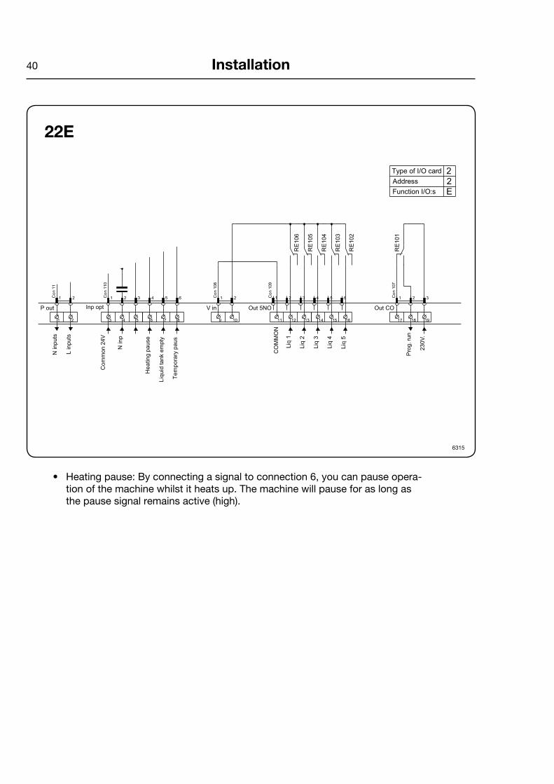
• Heatingpause:Byconnectingasignaltoconnection6,youcanpauseopera-tion of the machine whilst it heats up. The machine will pause for as long as the pause signal remains active (high).

41Installation
22FCo
n 11
1
1 2 Con 110 1 2 3 4 5 6 Con
108
1 2 Con
109
1 2 3 4 5 6
RE10
6
RE10
5
RE10
4
RE10
3
RE10
2
Con 107 1 2 3
RE10
1
Address
Inp
Con
115
Function I/O:s
PTD
5
Type of I/O card
+5V
Start permitted
Central booking / paymentEBS / PCB / Camping
230V
0V
+24V
24V
Start permitted
Central booking / paymentEBS / PCB / Camping
Neu
tral
Line Co
m. 2
4V(-)
Com
. 100
-240
V
Bloc
king
of s
tart
Hea
ting
paus
e
Liq.
det
. em
pty
Tem
pora
ry p
ause
Com
mon
out
puts
Pow
er fo
r out
puts
Com
mon
Liqu
id d
et. s
ign
1
Liqu
id d
et. s
ign
2
Liqu
id d
et. s
ign
3
Liqu
id d
et. s
ign
4
Liqu
id d
et. s
ign
5
Prog
ram
run
NC
Prog
ram
run
NO
22F
Com
. 24V
(-)
Start permittedCentral paymentPlexa Compact
Status machine
M1 M1 S1 S1
Com
.
Com
.
Inpu
t 1
Inpu
t 2
Inpu
t 3
Inpu
t 4
Out
put 1
Out
put 2
Out
put 3
Out
put 4
Out
put 5
Out
put 6
NC
Out
put 6
NO
6944
• Thecentralpaymentorbookingsystemshalltransmitanactive(high)signaltothe washing machine once permission has been granted to start the machine. The signal must remain active (high) until the machine starts. A feedback signal will be present on connection 18 and remain active (high) whilst the wash programisrunning.Thefeedbacksignalispoweredby230Vfromconnection 19orexternal24V.
42
���
����
� �
����
���
����
���
����
��
���
���
� � � � � �
���
���
����
�����
����
�����
���
������
����
����
����
����
���
��
����
������
��
���
��
� �
���
���
������
����
��
���
�����
�����
����
���
���
� � � � � �
���
���
����
����
�����
����
�
���
���
������
�����
����
�
���
���
������
�����
����
�
���
���
������
�����
����
�
���
���
������
�����
����
�
���
�
���
���
� � �
���
�����
����
���
�
���
�����
����
���
�����
�����
�������
���
���
����
��������������
���������������
��
���
� ��
� � � � � � � � � �� �� �� �� �� �� �� � ��
Installation
22G
6637
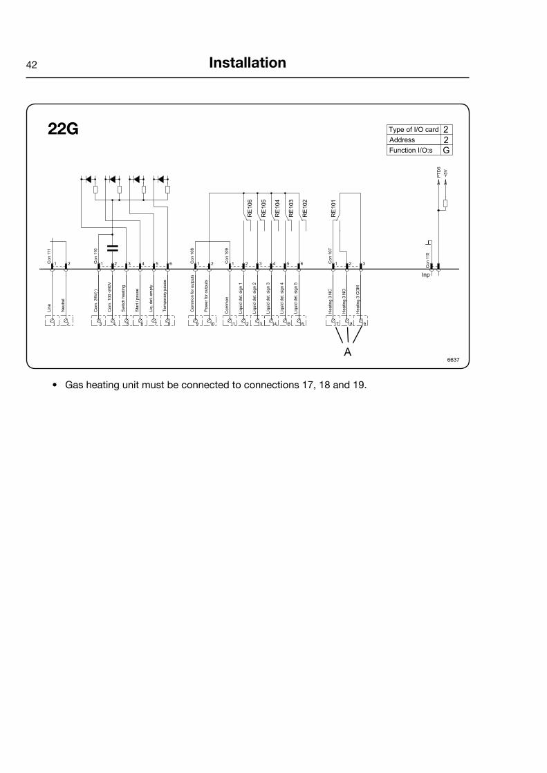
• Gas heating unit must be connected to connections 17, 18 and 19.
A

43
Machines with type 3 I/O
• By maintaining an activated (high) signal on connection 3 (”Price red”), the price of the wash program can be reduced. This function has a number of uses, including providing reductions during a specific period of the day. Whilst the signal remains activated (high), the price of the wash program is reduced by the percentage entered in the price pro-gramming menu.
6636
�
���
�
�����
�
���
�
����
�
���
� �� � � �� � � �
������� ���� ��� � �
���
����
�����
����
����
�����
����
������
�
�����
����
����
���
Installation
44 Installation
Electrical installation
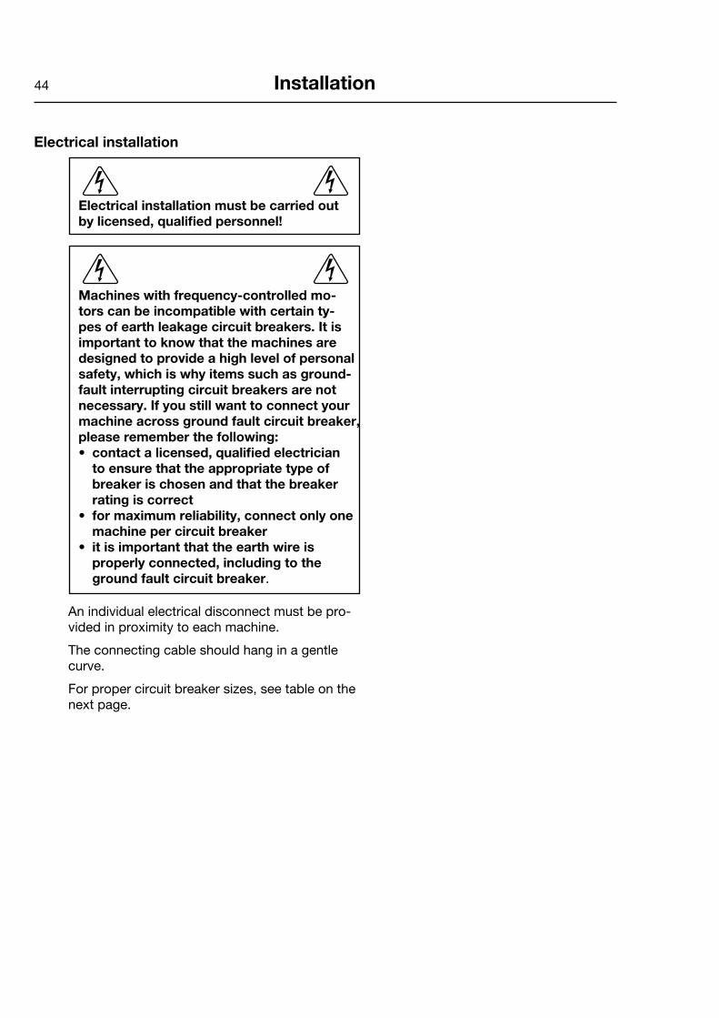
Electrical installation must be carried out by licensed, qualified personnel!
Machines with frequency-controlled mo-tors can be incompatible with certain ty-pes of earth leakage circuit breakers. It is important to know that the machines are designed to provide a high level of personal safety, which is why items such as ground-fault interrupting circuit breakers are not necessary. If you still want to connect your machine across ground fault circuit breaker, please remember the following:• contact a licensed, qualified electrician to ensure that the appropriate type of breaker is chosen and that the breaker rating is correct• for maximum reliability, connect only one machine per circuit breaker• it is important that the earth wire is properly connected, including to the ground fault circuit breaker.
An individual electrical disconnect must be pro-vided in proximity to each machine.
The connecting cable should hang in a gentle curve.
For proper circuit breaker sizes, see table on the next page.

45
Single-phase connection:
Connect the earth and other two wires as shown in example ”1AC” in the figure.
For the W645 and W662, special circuit breaker considerations must be made. The following gui-delines will assist you in selecting an appropriate circuit breaker.
W645: Select a 25 Amp circuit breaker capable of main-taining at 60 Amperes for 8 seconds.
W662: Select a 30 Amp circuit breaker capable of main-taining at 70 Amperes for 7 seconds.
Three-phase connection:
Connect the earth and the three phases as shown in example ”3AC” in the figure.
When the installation is completed, check:
• thatthedrumisempty.
• thatthemachineoperatesbyturningonthemains switch, starting the machine and using RAPID ADVANCE to reach the spin cycle (see operations manual).
IMPORTANTWhen making power supply connections to machines rated 208-240V AC, do not connect any phase measuring in excess of 125 V AC (with respect to earth ground) to the L1 or L2 terminals on the connection block. So-called "stinger legs" must be connected to the "L3" terminal, which does not feed power to the control circuits of the machine.
On three-phase models (except SU677), check that the drum rotates in the direction indicated on the machine while in extrac-tion. If the direction is incorrect, reverse two of the power line phases to correct the rotation direction, while observing the note above.
31
Installation
30
30
31
6524
�� ��
1AC
�� �� ��
6525
3AC

46
Heating Voltage Total Fuse alternative alternative kW A
No heating or Steam heating El heating
EX618
100-120V1AC 1.1 15 208-240V1AC 1.1 15 220-230V3AC 7 20
Heating Voltage Total Fuse alternative alternative kW A
No heating or Steam heating El heating
EX625
208-240V1AC 1.3 15 100-120V1AC 1.3 15 208-240V3AC 9.2 30
Heating Voltage Total Fuse alternative alternative kW A
No heating or Steam heating El heating
EX630
208-240V1AC 1.7 15 100-120V1AC 1.7 15 208-240V1AC 12.5 60 208-240V3AC 11.8 35 440/480V3AC 13.5 20
Installation

47
Heating Voltage Total Fuse alternative alternative kW A
No heating or Steam heating
EX675
208-240 V 1 AC 2.1 15 100-120 V 1 AC 2.1 15
Heating Voltage Total Fuse alternative alternative kW A
No heating or Steam heating
Heating Voltage Total Fuse alternative alternative kW A
No heating or Steam heating El heating
EX645
100-120 V 1 AC 2.4 15 208-240 V 1 AC 2.4 15
EX660
100-120/208-240 V 1 AC 3.0 15 480 V 1 AC 2.6 15 208-240 V 3 AC 18.3 60
Installation
48 Installation
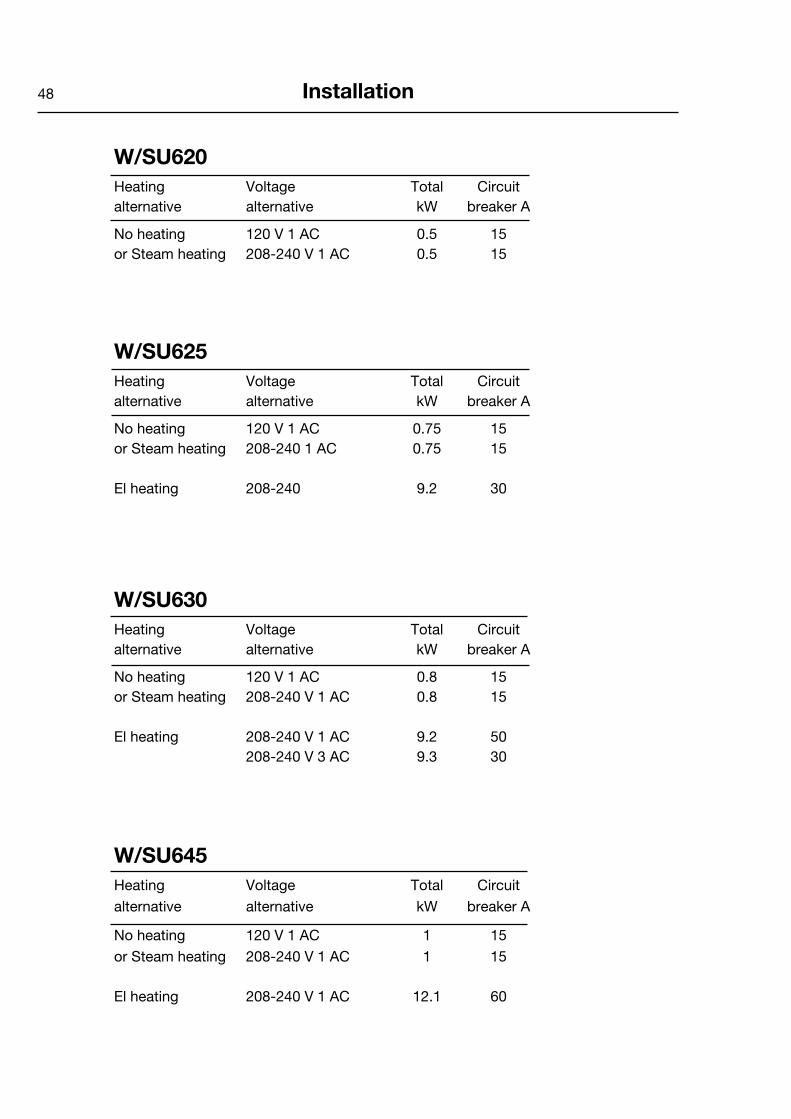
W/SU620Heating Voltage Total Circuit alternative alternative kW breaker A
Noheating 120V1AC 0.5 15 orSteamheating 208-240V1AC 0.5 15
W/SU625Heating Voltage Total Circuit alternative alternative kW breaker A
Noheating 120V1AC 0.75 15 or Steam heating 208-240 1 AC 0.75 15
El heating 208-240 9.2 30
W/SU630Heating Voltage Total Circuit alternative alternative kW breaker A
Noheating 120V1AC 0.8 15orSteamheating 208-240V1AC 0.8 15 Elheating 208-240V1AC 9.2 50 208-240V3AC 9.3 30
W/SU645Heating Voltage Total Circuit alternative alternative kW breaker A
No heating 120V1AC 1 15or Steam heating 208-240V1AC 1 15
Elheating 208-240V1AC 12.1 60
49Installation
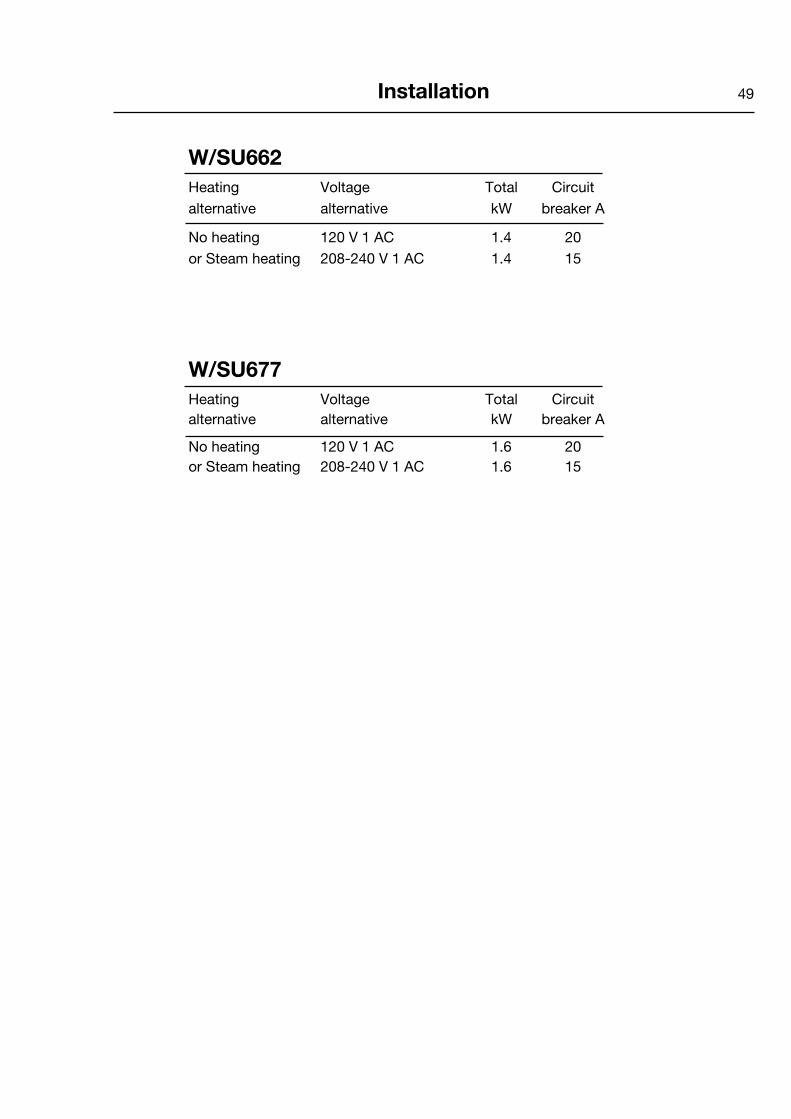
W/SU662Heating Voltage Total Circuit alternative alternative kW breaker A
No heating 120 V 1 AC 1.4 20 or Steam heating 208-240 V 1 AC 1.4 15
W/SU677Heating Voltage Total Circuit alternative alternative kW breaker A
No heating 120 V 1 AC 1.6 20 or Steam heating 208-240 V 1 AC 1.6 15


51
6217, 6179, 6204
1
6180
2
1
Function checks
Function checks
Compass Control
Perform the following checks once the machine is installed:
• Openthemanualwatervalves.
• Turnonthepowertothemachine.
• Putdetergentintocompartment2(Mainwash).
• Selecta"HOT"programwiththecontrolknob (1).
• Presstheknob.
Check:
• thatthedrumrotatesnormallyandthatthereare no unusual noises.
• thattherearenoleaksinwatersupply/drainconnections.
• thatwaterpassesthroughthedetergentcompartment and fabric conditioner compart-ment.
• thatthedoorcannotbeopenedduringapro-gram.
1
2
HOT


When reliable laundryand wetcleaningequipment is desired,the choice is Wascomat!The world’s oldest and leading manufacturer of commercial laundry equipment for coin laundries, hotels, motels, nursing homes and any other institutional laundry use, and the environmentally safe,wetcleaning “dual-use” systems for drycleaners.
WascomaT provides “peace of mind GuaranTee”Backed by a company that’s been in the laundry equipment business for over 100 years and has earned a reputation as the standard of quality worldwide, Wascomat dealers provide:– free survey of your laundry needs
– Laundry design and layout
– Quality laundry equipment in a size and model for every need
– installation, start-up and training
– Worldwide parts and service
– Best warranty in the business
– “Lease-a-Laundry Program”, which includes the laundry equipment installation and ongoing service
expand, modernize, reTooL or BuiLd a neW Laundry WiTh LoW-cosT financinG or LeasinG from WascomaT* With Wascomat/viking financing or leasing you can obtain and install durable, efficient, state-of-the-art Wascomat washers, dryers and non-polluting, environmentally-friendly wetcleaning equipment to meet all anti-pollution regulations.
for more information and to apply for financing or leasing, call viking financial services LLc 1-800-645-2209
* Fo
r q
ualifi
ed a
pp
lican
ts a
nd e
qui
pm
ent
only
.

Wascomat provides efficient, quality washers, dryers, flatwork ironers andnon-polluting wetcleaning equipment.
for parts & customer service You can depend onWascomat & its dealers
The Standard of Quality for Over 100 Years!
* For qualified applicants and equipment only.
Wascomat provides the best customer service With experienced WorldWide customer support, With an over 100-year track record.
Wascomat/ viking Financial services provides loW cost Financing and leasing* For your business groWth.
Front-load Washer modelsSolid and soft-mount, coin operated and commercial laundry washers in standard, high and ultra-high extract models. Designed for long life and efficient water and energy use. Available from 18 to 250 lb. capacities.
side-load Washer modelsPullman, Side-Load, Barrier and Clean Room washer models with high 300 to 350 G-Force extrac-tion, designed and built for long, trouble-free life and big water and energy savings. Available from 55 to 250 lb. capacities.
gas eFFicient dryer modelsCoin operated and commercial energy and gas efficient, user friendly TD dryer models with optional unique Wascomat Residual Moisture Control (RMC). Available in a size and model for every laundry need.
automatic FlatWork ironersA unique one-operator, fully automatic, labor saving, ironer that does it all: feeds, irons, folds, stacks and counts. Also available in fully and semi-automatic
models in a size and model for every laundry need.
Wascomat non-polluting Wetclean equipment The best alternative to Perc, uses water and complies with OSHA, EPA and all other environmental, anti-pollution regulations. Wascomat state-of-the-art wetclean technolo-gy eliminates all pollution concerns and provides the best wetcleaning and washing results. Available in asize and model for every wetcleaning need.
With the push of a button, the unique Wascomat “Dual-Use” Wetcleaner converts to an ideal laundry washer for washing shirts, comforters, drapes, all other washable garments and cleaner’s wash-dry-fold customer service.
for more information call Wascomat at 516-371-4400