u-control - meditech€¦ · in the worst case, ... • simultaneous connection of a patient to a...
TRANSCRIPT

MYOTRAC INFINITI U-CONTROL

MYOTRAC Infiniti™ U-Control User Guide 2

MYOTRAC Infiniti™ U-Control User Guide 3
The Manufacturer: Thought Technology Ltd. 2180 Belgrave Avenue Montreal, Quebec, Canada H4A 2L8
Product Name: MYOTRAC Infiniti System Product #: T9800 Device Name: MYOTRAC Infiniti Encoder Device #: SA9800

MYOTRAC Infiniti™ U-Control User Guide 4
• Type BF Equipment
• Internally powered equipment • Continuous operation
• Read Instruction Manual
• The pins of the connectors identified with the ESD warning symbol should not be touched unless ESB precautionary procedures are used.
CAUTION • US Federal Law restricts this device to sale by, or on order of, a physician or any other
practitioner licensed by the law of the state in which he or she practices to use or order the use of this device.
WARNING • Do not operate Active Sensors within 10 feet of an operating cellular phone, similar radio
transmitting device, other powerful radio interference producing sources such as arc welders, radio thermal treatment equipment, x-ray machines, or any other equipment that produces electrical sparks. Portable and mobile RF communication equipment can affect this equipment.
• With the MyoTrac Infiniti Encoder SA9800 use only with supplied power supply. GlobTek Part Number WR92B2500LF9P-Y-MED (WR95/WR93/WR97) or GS889
• The PC used with MYOTRAC Infiniti must be placed outside the patient/client environment (more than 3 meters or 10 feet) or the PC must comply with EN60601-1 (system safety).
• After use, the Batteries or the Battery pack must be disposed of in accordance with local, state and federal regulations and laws.
• After use, the Disposable Electrodes may be a biohazard. Handle, and when applicable, dispose of these materials in accordance with accepted medical practice and any applicable local, state and federal laws and regulations.
• Reusable electrodes present a potential risk of cross-infection especially when used on abraded skin, unless they are restricted to a single patient or sterilized between patients. If sterilizing electrodes, employ only gas sterilization.
• Radiated radio frequency electromagnetic fields can cause performance degradation in the MyoScan-Pro EMG sensor. In the worst case, an RF field strength of 22mV/M can cause an increase of 1μV in the signal reading from a MyoScan-Pro sensor. Be sure to keep in mind that a very relaxed muscle should provide an EMG reading of approximately 1-3μV.
• This device is capable of generating current densities exceeding 2mA r.m.s./cm² this may require special attention of the operator.
• Do not exceed 0.1watts/cm² with recommended electrodes, assuming a load of 500Ω. 1. St Cloud = Max 100mA 2. Femelex = Max 100mA
• Avoid accidental contact between connected but unused applied parts and other conductive parts including those connected to protective earth.
• Explosion Hazard; Do not use in the presence of a flammable anesthetic mixture with air, or with Oxygen or Nitrous Oxide.
• Not to be immersed in water. • Take care in arranging patient and sensor cables to avoid risk of patient entanglement or
strangulation. • The operator is responsible for ensuring the safety of any devices controlled or triggered by
Infiniti equipment or software, or by any software or hardware receiving data from Infiniti equipment. Infiniti equipment must not be configured or connected in such a way that failure in its data acquisition, processing or control functions can trigger patient feedback stimulus that poses an unacceptable level of risk.
• Use of any equipment in a biofeedback or stimulation context should be immediately terminated upon any sign of treatment-related distress or discomfort.
• Not to be connected to a patient undergoing MRI, Electro surgery or defibrillation. • Simultaneous connection of a patient to a high frequency surgical equipment may result in
burns at the site of the stimulator electrodes and possible damage to the stimulator.

MYOTRAC Infiniti™ U-Control User Guide 5
• Operations in close proximity (e.g. 1 m) to shortwave or microwave therapy equipment may produce instability in the stimulation output.
• The long-term effects of chronic electrical stimulation are unknown. • Stimulation should not be applied over the carotid sinus nerves, particularly in patients with
a known sensitivity to the carotid sinus reflex. • Stimulation should not be applied over the neck or mouth. Severe spasm of the laryngeal
and pharyngeal muscles may occur and the contractions may be strong enough to close the airway or cause difficulty in breathing.
• Patients with an implanted electronic device (for example a cardiac pacemaker) should not be subjected to stimulation unless specialist medical opinion has first been obtained.
• Stimulation should not be applied transthoracically in that the introduction of electrical current into the heart may cause cardiac arrhythmias.
• Stimulation should not be applied transcerebrally. • Stimulation should not be applied over swollen, infected, or inflamed areas or skin
eruptions, e.g., phlebitis, thrombophlebitis, varicose veins, etc. • Stimulation should not be applied over, or in proximity to, cancerous lesions. • Not for use with patients with undiagnosed pain conditions. • Only use the unit for which it was prescribed. • Do not immerse the unit in water or any other liquid substance. • Do not use if you have symptoms of bladder infection. • Do not use with diminished mental capacity or physical competence limiting the use of the
device. PRECAUTIONS • Safety of powered muscle stimulators for use during pregnancy has not been established. • Caution should be used for patients with suspected or diagnosed heart problems.
• Caution should be used for patients with suspected or diagnosed epilepsy. • Caution should be used in the presence of the following:
1. When there is a tendency to hemorrhage following acute trauma or fracture; 2. Following recent surgical procedures when muscle contraction may disrupt the
healing process; 3. Over the menstruating or pregnant uterus; and 4. Over areas of the skin which lack normal sensation.
• Some patients may experience skin irritation or hypersensitivity due to the electrical stimulation or electrical conductive medium. The irritation can usually be reduced by using an alternate conductive medium, or alternate electrode placement.
• Electrode placement and stimulation settings should be based on the guidance of the prescribing practitioner.
• Powered muscle stimulators should be kept out of the reach of children. • If damage is evident of the unit or accessories, discontinue use and contact your supplier
for further information on repair. • Powered muscle stimulators should be used only with the leads and electrodes
recommended for use by the manufacturer. • Portable powered muscle stimulators should not be used while driving, operating
machinery, or during any activity in which involuntary muscle contractions may put the user at undue risk of injury.
• The system should not be used adjacent to or stacked with other equipment, if used adjacent or stacked the unit should be observed to verify normal operation in the configuration in which it will be used.
• Use of accessories, transducers or cables other than those specified by Thought Technology ltd may result in increased emissions or decreased immunity of the equipment to electromagnetic energy.
• Always clean applicator after each use according to instructions
ATTENTION • Sensors and equipment damaged by static electricity are not covered under warranty. To
prevent static discharge from damaging the sensor and/or encoders, use anti-static mats or sprays in your working area. A humidifier may also be used to prevent static environments by conditioning hot, dry air. It is recommended that all staff involved with the unit receive an

MYOTRAC Infiniti™ U-Control User Guide 6
explanation of the ESD symbol and the precautions described above as a minimum. • Do not apply any electrode gel or equivalent directly on the sensor snaps. Always use
electrodes as a medium between the sensor and the client. • Not for diagnostic purposes, not defibrillator proof, not for critical patient monitoring. • To prevent voiding warranty by breaking connector pins, carefully align white guiding dot on
sensor plug with slot on sensor input. • Make sure to remove electrodes from sensor snaps immediately after use. • Do not plug third party sensors directly into instrument inputs. Plug only Thought
Technology Active Sensor cable connectors into instrument inputs. All electrodes and third party sensors must be connected to active sensors, either directly or through an adapter.
• Remove batteries when the device is not being used for an extended period of time. Please dispose of battery following local regulations.
ADVERSE REACTIONS Skin irritation and burns beneath the electrodes have been reported with the use of powered muscle
stimulators.
CONTRAINDICATIONS • Powered muscle stimulators should not be used on patients with cardiac demand
pacemakers. • Do Not use if you have colorectal cancer or lesions in the rectal area, symptoms of an active
urinary tract infections
INTENDED PURPOSE • Acute and ongoing treatment of stress, urge or mixed urinary incontinence and where the
following results may improve urinary control: Inhibition of the detruser muscle through reflexive mechanisms.
• Incontinence treatment for assessing EMG activity of the pelvic floor and accessory muscles such as the abdominal or gluteal muscles
• Powered muscle stimulators should only be used under medical supervision for adjunctive therapy for the treatment of medical diseases and conditions
NOTE • No preventative inspections required; maintenance must be performed by qualified personnel.
Factory re-calibration can be requested. • The supplier will make available, upon request, circuit diagrams, component parts lists and
description or other information required for the repair of product by qualified personnel. • The operator must be familiar with typical characteristics of signals acquired by this
equipment, and be able to detect anomalies in the acquired signal that could interfere with treatment effectiveness. Depending on the importance of signal integrity, it may be advisable to continuously monitor the raw signals, in time and/or frequency domain, while the device is being used for biofeedback or other purposes. If anomalies are observed on acquired signals, and if you suspect a problem with electromagnetic interference, contact Thought Technology for a technical note on identification and remediation.
• This product conforms to standards EN60601-1, EN60601-2-10 and EN60601-2-40; some encoder labeling may indicate superceded standards.
MAINTENANCE AND CALIBRATION • Wipe encoder with a clean cloth • Factory testing and calibration ensure equipment accuracy and frequency response. Contact
Thought Technology for factory re-calibration if necessary.
STORAGE • Store in its original case at up to 90% humidity / 30C°
TRANSPORTATION • Transport in its original case
Manual # SA9813 Rev 4

MYOTRAC Infiniti™ U-Control User Guide 7
Guidance and manufacturer’s declaration – electromagnetic immunity
The MYOTRAC Infiniti is intended for use in the electromagnetic environment specified below. The customer or the user of the MYOTRAC Infiniti should assure that it is used in such an environment, and that precautions regarding that environment are heeded.
Immunity test
IEC 60601 test level
Compliance level Electromagnetic environment – guidance
Electrostatic discharge (ESD) IEC 61000-4-2
±6 kV contact ±8 kV air
±6 kV contact ±8 kV air
Floors should be wood, concrete or ceramic tile. If floors are covered with synthetic material, the relative humidity should be at least 30 %.
Electrical fast transient/burst IEC 61000-4-4
±2 kV for power supply lines ±1 kV for input/output lines
±2 kV for power supply lines ±1 kV for input/output lines
Mains power quality should be that of a typical commercial or hospital environment.
Surge IEC 61000-4-5
±1 kV differential mode ±2 kV common mode
±1 kV differential mode ±2 kV common mode
Mains power quality should be that of a typical commercial or hospital environment.
Voltage dips, short interruptions and voltage variations on power supply input lines IEC 61000-4-11
<5 % UT
(>95 % dip in UT) for 0,5 cycle 40 % UT
(60 % dip in UT) for 5 cycles 70 % UT
(30 % dip in UT) for 25 cycles <5 % UT
(>95 % dip in UT) for 5 sec
<5 % UT
(>95 % dip in UT) for 0,5 cycle 40 % UT
(60 % dip in UT) for 5 cycles 70 % UT
(30 % dip in UT) for 25 cycles <5 % UT
(>95 % dip in UT) for 5 sec
Mains power quality should be that of a typical commercial or hospital environment. If the user of the Infiniti requires continued operation during power mains interruptions, it is recommended that the MYOTRAC Infiniti be powered from an uninterruptible power supply or a battery.
Power frequency (50/60 Hz) magnetic field IEC 61000-4-8
3 A/m
3 A/m
Power frequency magnetic fields should be at levels characteristic of a typical location in a typical commercial or hospital environment.
NOTE UT is the a.c. mains voltage prior to application of the test level.
MYOTRAC Infiniti™ U-Control User Guide 8
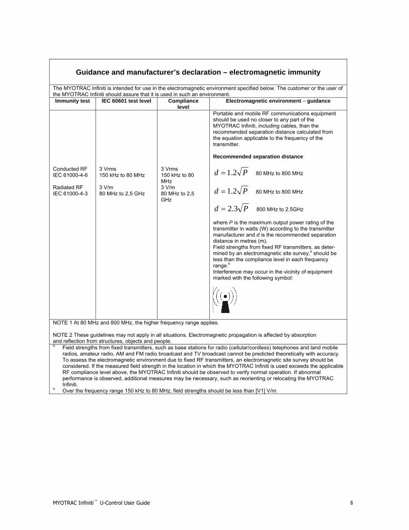
Guidance and manufacturer’s declaration – electromagnetic immunity
The MYOTRAC Infiniti is intended for use in the electromagnetic environment specified below. The customer or the user of the MYOTRAC Infiniti should assure that it is used in such an environment. Immunity test IEC 60601 test level Compliance
level Electromagnetic environment – guidance
Portable and mobile RF communications equipment should be used no closer to any part of the MYOTRAC Infiniti, including cables, than the recommended separation distance calculated from the equation applicable to the frequency of the transmitter. Recommended separation distance
Conducted RF IEC 61000-4-6
3 Vrms 150 kHz to 80 MHz
3 Vrms 150 kHz to 80 MHz
Pd 2.1= 80 MHz to 800 MHz
Radiated RF IEC 61000-4-3
3 V/m 80 MHz to 2,5 GHz
3 V/m 80 MHz to 2,5 GHz
Pd 2.1= 80 MHz to 800 MHz
Pd 3.2= 800 MHz to 2.5GHz
where P is the maximum output power rating of the transmitter in watts (W) according to the transmitter manufacturer and d is the recommended separation distance in metres (m). Field strengths from fixed RF transmitters, as deter-mined by an electromagnetic site survey,a should be less than the compliance level in each frequency range.b
Interference may occur in the vicinity of equipment marked with the following symbol:
NOTE 1 At 80 MHz and 800 MHz, the higher frequency range applies. NOTE 2 These guidelines may not apply in all situations. Electromagnetic propagation is affected by absorption and reflection from structures, objects and people. a Field strengths from fixed transmitters, such as base stations for radio (cellular/cordless) telephones and land mobile
radios, amateur radio, AM and FM radio broadcast and TV broadcast cannot be predicted theoretically with accuracy. To assess the electromagnetic environment due to fixed RF transmitters, an electromagnetic site survey should be considered. If the measured field strength in the location in which the MYOTRAC Infiniti is used exceeds the applicable RF compliance level above, the MYOTRAC Infiniti should be observed to verify normal operation. If abnormal performance is observed, additional measures may be necessary, such as reorienting or relocating the MYOTRAC Infiniti.
b Over the frequency range 150 kHz to 80 MHz, field strengths should be less than [V1] V/m.

MYOTRAC Infiniti™ U-Control User Guide 9
Recommended separation distances between portable and mobile RF communications equipment and the MYOTRAC Infiniti
The MYOTRAC Infiniti is intended for use in an electromagnetic environment in which radiated RF disturbances are controlled. The customer or the user of the MYOTRAC Infiniti can help prevent electromagnetic interference by maintaining a minimum distance between portable and mobile RF communications equipment (transmitters) and the MYOTRAC Infiniti as recommended below, according to the maximum output power of the communications equipment.
Separation distance according to frequency of transmitter Rated maximum output power of transmitter
W 150 kHz to 80 MHz 80 MHz to 800 MHz
800 MHz to 2,5 GHz
Pd 2.1= Pd 2.1= Pd 3.2=
0,01 0.12 0.12 0.23 0,1 0.38 0.38 0.73 1 1.2 1.2 2.3
10 3.8 3.8 7.3 100 12 12 23
For transmitters rated at a maximum output power not listed above, the recommended separation distance d in metres (m) can be estimated using the equation applicable to the frequency of the transmitter, where P is the maximum output power rating of the transmitter in watts (W) according to the transmitter manufacturer. NOTE 1 At 80 MHz and 800 MHz, the separation distance for the higher frequency range applies. NOTE 2 These guidelines may not apply in all situations. Electromagnetic propagation is affected by absorption and reflection from structures, objects and people.
Guidance and manufacturer’s declaration – electromagnetic emissions
The MYOTRAC Infiniti is intended for use in the electromagnetic environment specified below. The customer or the user of the MYOTRAC Infiniti should assure that it is used in such an environment. Emissions test Compliance Electromagnetic environment – guidance
RF emissions CISPR 11
Group 1 The MYOTRAC Infiniti uses RF energy only for its internal function. Therefore, its RF emissions are very low and are not likely to cause any interference in nearby electronic equipment.
RF emissions CISPR 11
Class B
Harmonic emissions IEC 61000-3-2
Not applicable
Voltage fluctuations/ flicker emissions IEC 61000-3-3
Not applicable
The MYOTRAC Infiniti is suitable for use in all establishments, including domestic establishments and those directly connected to the public low-voltage power supply network that supplies buildings used for domestic purposes.

MYOTRAC Infiniti™ U-Control User Guide 10
Table of Contents About This Guide......................................................................................................................................................................... 11 Chapter 1 ...................................................................................................................................................................................... 12
Introduction to your MYOTRAC INFINITI™ U-CONTROL Encoder ........................................................................................ 12 System Requirements .............................................................................................................................................................. 13 MYOTRAC INFINITI U-CONTROL Components ..................................................................................................................... 14 Connection to the Client ........................................................................................................................................................... 17 Connection to the PC ............................................................................................................................................................... 19 Screen Elements ...................................................................................................................................................................... 20 Thought Support....................................................................................................................................................................... 20 Settings Menu .......................................................................................................................................................................... 21
Chapter 2 ...................................................................................................................................................................................... 25 SEMG sessions on your MYOTRAC INFINITI™ U-CONTROL Encoder................................................................................. 25 Open SEMG Sessions ............................................................................................................................................................. 25 Script Sessions......................................................................................................................................................................... 27
Chapter 3 ...................................................................................................................................................................................... 28 STIM sessions on your MYOTRAC INFINITI™ U-CONTROL Encoder................................................................................... 28 Open STIM Session ................................................................................................................................................................. 30 Script Stim Sessions ................................................................................................................................................................ 32
Chapter 4 ...................................................................................................................................................................................... 34 EMG-Stim on your MYOTRAC INFINITI™ U-CONTROL Encoder.......................................................................................... 34
Chapter 5 ...................................................................................................................................................................................... 38 Data Management on your MYOTRAC INFINITI™ U-CONTROL Encoder............................................................................. 38 MYOTRAC INFINITI U-CONTROL Review.............................................................................................................................. 39
Chapter 6 ...................................................................................................................................................................................... 40 Display Options on your MYOTRAC INFINITI™ U-CONTROL Encoder ................................................................................. 40 Displays.................................................................................................................................................................................... 40
Chapter 7 ...................................................................................................................................................................................... 44 Flow on your MYOTRAC INFINITI™ U-CONTROL Encoder.................................................................................................. 44
Chapter 8 ...................................................................................................................................................................................... 45 Reference................................................................................................................................................................................. 45 Technical Support and Order Placing ...................................................................................................................................... 46 Technical Support .................................................................................................................................................................... 46 Product Numbers & Accessories.............................................................................................................................................. 47 Placing Orders.......................................................................................................................................................................... 48 Specifications ........................................................................................................................................................................... 49 MYOTRAC Infiniti Hardware Copyright Notice........................................................................................................................ 53

MYOTRAC Infiniti™ U-Control User Guide 11
About This Guide
Welcome to the MYOTRAC INFINITI™ U-CONTROL encoder. This guide is designed to help you get up and running quickly with your new encoder. It will describe the operation of the encoder, and how it interfaces to the host personal computer (PC). It walks you through: • Physical Operation of the encoder. • EMG, STIM and EMG-STIM sessions. • Data management. • Display options.
After you have become familiar with the key concepts of your new encoder, you can use the rest of this guide as a reference for less common tasks, and also as a source of information if you have problems operating it.

MYOTRAC Infiniti™ U-Control User Guide 12
Chapter 1
Introduction to your MYOTRAC INFINITI™ U-CONTROL Encoder
This chapter explains the physical interface with the MYOTRAC INFINITI U-CONTROL Encoder, how to use it for the first time, and how to transfer data to the host PC.
Getting to know your MYOTRAC INFINITI U-CONTROL Encoder
What is a MYOTRAC INFINITI U-CONTROL Encoder? The MYOTRAC INFINITI U-CONTROL is the cutting edge in handheld, dual channel Surface Electromyography (SEMG) combined with single channel Muscle Stimulation (STIM) for urinary incontinence. With it you will be able to deliver targeted and customized treatment directly to the client’s clinically relevant areas. The total integration of the two modalities of SEMG and STIM in a single device provides a third modality of treatment- SEMG-STIM, with features such as EMG-Triggered Stimulation and Alternating EMG and STIM. A simple first approach has been adopted in the design of the MYOTRAC INFINITI U-CONTROL to make it as easy and fast as possible to get the clinical results desired from this powerful device. Customizing the MYOTRAC INFINITI U-CONTROL to your clinical needs couldn’t be easier; all users input is directed through a series of intuitive and guided screens using touch screen technology. The partnership of the MYOTRAC INFINITI U-CONTROL with the BioGraph Infiniti PC software enhances yet further the power and flexibility of the MYOTRAC INFINITI U-CONTROL. This link enables you to transfer session data to the PC for further viewing, analysis and reporting, in real time or post session.

MYOTRAC Infiniti™ U-Control User Guide 13
System Requirements To install the BioGraph Infiniti software, your computer system must meet or exceed the following requirements.
Recommended Minimum • IBM PC compatible
(Intel/Pentium/Celeron family or AMD K6/Athlon/Duron family, CPU P4 speed 3 GHz or higher), Desktop or Laptop with two monitor capability
• Windows 2000/XP Professional or Home edition.
• 50 - 60 gigabytes hard disk space for video recording and processing. (The software needs 2.5 gigabytes to install and run on available hard drive space)
• Memory, 512 MB of RAM or more • CD ROM or DVD drive • SVGA graphic card (1024 x 768) or higher
resolution adapter & monitor • 32 bit Sound Blaster compatible sound
card & speakers • 1 to 4 USB ports, depending on the
desired number of MYOTRAC INFINITI U-CONTROL encoders
• Mouse or compatible pointing device • MS Word 97 or higher (for printing
purposes) • Compact Flash Reader (For use with
compact flash card only) • Webcam 30 frames per second (for video
purposes only) NOTE: When using certain more complex screens, you must adhere to the Recommended Computer Requirements. •
• IBM PC compatible (Intel/Pentium/Celeron family or AMD K6/Athlon/Duron family, CPU P3 speed 1.8 GHz), Desktop or Laptop
• Windows 2000/XP Professional or Home edition.
• 10 - 20 gigabytes hard disk space • (The software needs 2.5 gigabytes to
install and run on available hard drive space)
• Memory, 256 MB of RAM or more • CD ROM or DVD drive • SVGA graphic card (1024 x 768) or
higher resolution adapter & monitor • 16 Bit Sound Blaster compatible
sound card & speakers • 1 to 4 USB ports, depending on the
desired number of MYOTRAC INFINITI U-CONTROL encoders
• Mouse or compatible pointing device • Word 97 or higher (for printing
purposes) NOTE: For most recent computer requirements contact Thought Technology Ltd for MAR473
Update information
Periodically updates may become available for the BioGraph Infiniti software and for the MYOTRAC INFINITI U-CONTROL Hardware. Please contact your local distributor or visit our website www.thoughttechnology.com for further information on how to obtain updates.

MYOTRAC Infiniti™ U-Control User Guide 14
MYOTRAC INFINITI U-CONTROL Components
• Compact Flash for increased memory capacity and one method for transfer of data to the PC. • USB for real time transfer of data to the PC (clinical version only). • Touch screen enables graphically guided navigation through the software. • Rugged Ergonomic Case, easy to hold or attach to the subject and will withstand the rigors of
daily use. • Battery Charging jack for wall connection enables fast built-in battery charging. • Headphone Jack for stereo sound feedback (or use the built-in speaker). • Push button On/Off switch to prevent accidental switching. • 2 Channels of Surface EMG and 1 channel of stimulation through the same electrodes; saves
time and increases flexibility.

MYOTRAC Infiniti™ U-Control User Guide 15
Power
There are three basic methods to power the MyoTrac Infiniti U-Control unit: Inserting batteries into the battery compartment of the unit, plugging it into the wall using the supplied AC adapter, or plugging it into a powered up computer using a USB cable. The MyoTrac Infiniti U-Control is available with battery charging capabilities. It will work with four standard Alkaline AAA batteries available in all consumer electrical stores. It is also possible to run the unit on removable, externally rechargeable batteries. A rechargeable battery pack is supplied with the MyoTrac Infiniti and can be charged while still inside the unit. Note: When changing batteries it is recommended to plug the unit into external power, either USB or wall transformer so that data is not lost. Failure to supply external power will result in data and script loss. The battery compartment cover slides open by pushing up using the notch provided. Place four AAA batteries in the slots, observing the polarity as illustrated. Please note that a diagram of the correct battery polarity is embossed on the inside surface of the compartment. Alternatively it is possible to use a rechargeable battery pack (Thought Technology Part Number MI1028). This battery pack is plugged into the connector in the battery compartment marked BATT. The pack then fits into the normal battery area. Note: only use battery packs from Thought Technology or authorized representative, as use of other battery packs will damage the device. A wall mounted AC power adapter, supplied with the MyoTrac Infiniti U-Control, is used to connect the unit to an electrical outlet. This can be used in conjunction with the batteries or without. The unit can also be powered from the computer via the USB cable. The cable is connected to the unit on one side and on the other side to the USB port of the computer. This can be used in conjunction with the batteries or without.
Charging the Batteries
Note: exact power supply subject to change without notice.

MYOTRAC Infiniti™ U-Control User Guide 16
Internal Charger If your MYOTRAC INFINITI U-CONTROL was supplied with a wall mounted AC adapter it is possible to charge the battery pack while it is inserted in the device. Note: Only use Thought Technology Ltd supplied wall mounted chargers with this device. Failure to do so could result in potential injury. Use only GlobTek Part Number WR9אB2500LCP-Y-MED where 2 =א for North America, 3=א for Europe, 5=א for United Kingdom and 7=א for Australia with the exception of Japan where the part number is GS 889. To start the charging plug in either the wall mounted AC adaptor or the USB cable. A full charging cycle from fully empty to fully charged will take approximately 2hrs for AC adaptor and 5.5hrs for the USB cable. The unit can be used while plugged in to either power source. The charging cycle does not need to be completed in full; it can be stopped at anytime by removing the connector. When the unit is turned off while plugged into an external power source, the screen displays a battery symbol. Charging action is shown with an animation of the battery filling up. When the battery is fully charged, the symbol shows a full battery. If the unit is plugged into an external power source while it is turned off, it will start charging within one minute. The state of the battery charging is available by going to the power menu in the settings menu of the device. It indicates the current mode of power and whether the unit is currently charging the batteries. Note: The rechargeable batteries must be fully charged prior to initial use. In order for the batteries to reach full capacity it may be necessary to charge them several times (~2-8) after initial use.
Memory
Recorded data can be saved using three methods - choose the one which most closely matches your usage needs. To select saving method, select the Settings menu from the main menu, and tap on the Save icon. Note data can only be recorded from EMG sessions not from Stim sessions. • Internal Memory – Limited size, only the statistical summaries are recorded. Specifically, the
statistics for 13 open sessions or 9 training sessions (work/rest) or 6 assessment sessions (work/rest + fast-flick + endurance) can be recorded. Data can be lost if the batteries are removed from the unit for longer than a few minutes.
• Compact Flash Card – Most flexible method of data saving: save all the raw data for review on the encoder or for download to the PC. Available in most electronics stores in a range of memory sizes. Since all EMG data is recorded, the amount of data that is saved to the compact flash card depends on the size of the card:
64MB 1.75 hours 128MB 3.5 hours 256MB 7 hours 512MB 14 hours 1GB 27.5 hours 2GB 55.5 hours

MYOTRAC Infiniti™ U-Control User Guide 17
The encoder is delivered with a protective insert in the compact flash slot. To remove it, push the button next to the slot once to eject the card. The CF card can then be inserted; you will notice that the CF card can only be inserted one way into the encoder to protect from incorrect insertion. When inserted properly it will be flush with the encoder rear. Follow the procedure above to remove this card when no longer required, and re-insert the protective insert. CF cards require a CF card reader to transfer data to the PC. The CF cards and reader can be purchased from most computer stores. Before its first use in the encoder, a CF card requires PC formatting using the file manager, then format the card using the BioGraph Infiniti Main Application. Formatting and transferring CF data to the PC is covered in depth in the BioGraph Infiniti software manual.
• Real Time PC Transfer – Connect to the PC via the USB and save and display the data on the PC in real time. See the following section “Connection to the PC”.
Attention: Do not remove the CF card without first stopping recording. If the CF card is removed during recording, you will lose all the data for the current session.
Tapping
Like using a mouse on a computer screen the MYOTRAC INFINITI U-CONTROL allows you to use your finger or a stylus to tap the buttons directly on the screen. The first time you start your handheld unit, or if the power has been disconnected for a while, you will be guided through a set of welcome screens including calibration, time and date setting. The calibration aligns the internal circuitry of the encoder with its touch sensitive screen so that when you tap a button on the screen, the handheld unit can detect exactly which button is being pressed. It is recommended to use a stylus when calibrating the device as it will provide a more accurate calibration than using a finger. Note: Always use a finger or stylus for tapping the screen. Never use a pen, pencil or other marking or sharp object on the screen. Damage resulting from misuse of the screen is not covered by the warranty. The software is designed so that once the screen has been calibrated it is possible to use all the buttons with a finger. In many cases the touch sensitive area is greater than the graphical constraints of the button allowing for easier operation using a finger. As necessary wipe screen with a dry cloth to clean. Screen protectors are available from good stationary suppliers and are a good way to extending the life of your screen.
Connection to the Client Depending on the type of session you are going to record there are different ways to connect the two channels to the client. • EMG only – Either plug the extender cable into the device directly and connect to the client
with EMG or Stimulation electrodes, or plug them into the pre-amplifier and the pre-amplifier into the MYOTRAC INFINITI U-CONTROL.
• Stim only – Plug the extender cable into the device directly and connect to stimulation electrodes, selecting the appropriate size stim electrode for the treatment to be delivered.
• EMG-STIM – As the session contains a stimulation element follow the stim instructions, connecting only using the extender cable, ensure that you use stim electrodes not SEMG electrodes.
Attention: Do not use SEMG type electrodes for Stim or EMG-STIM Sessions.

MYOTRAC Infiniti™ U-Control User Guide 18
Attention: When you insert the extender cable (lead wire) into the electrode connector, MAKE SURE THAT NO BARE METAL OF THE PINS IS EXPOSED. Attention: When using stimulation ensure that the intensity is set below the maximum for the selected electrode size. This is assuming an electrode impedance of 500Ω or 1kΩ respectively. St Cloud Vaginal = Max 100mA / 74mA Femelex = Max 100mA Note: If an external pre-amplifier is connected to the device all stim settings are disabled to protect the circuitry of the amplifier.
When connecting a sensor or extender cables, be sure to properly line up the guiding dot on the top of the plug with the notch in the encoder's input socket. Forcing the plug into the jack in any other position may damage your equipment.
MYOTRAC Infiniti™ U-Control User Guide 19
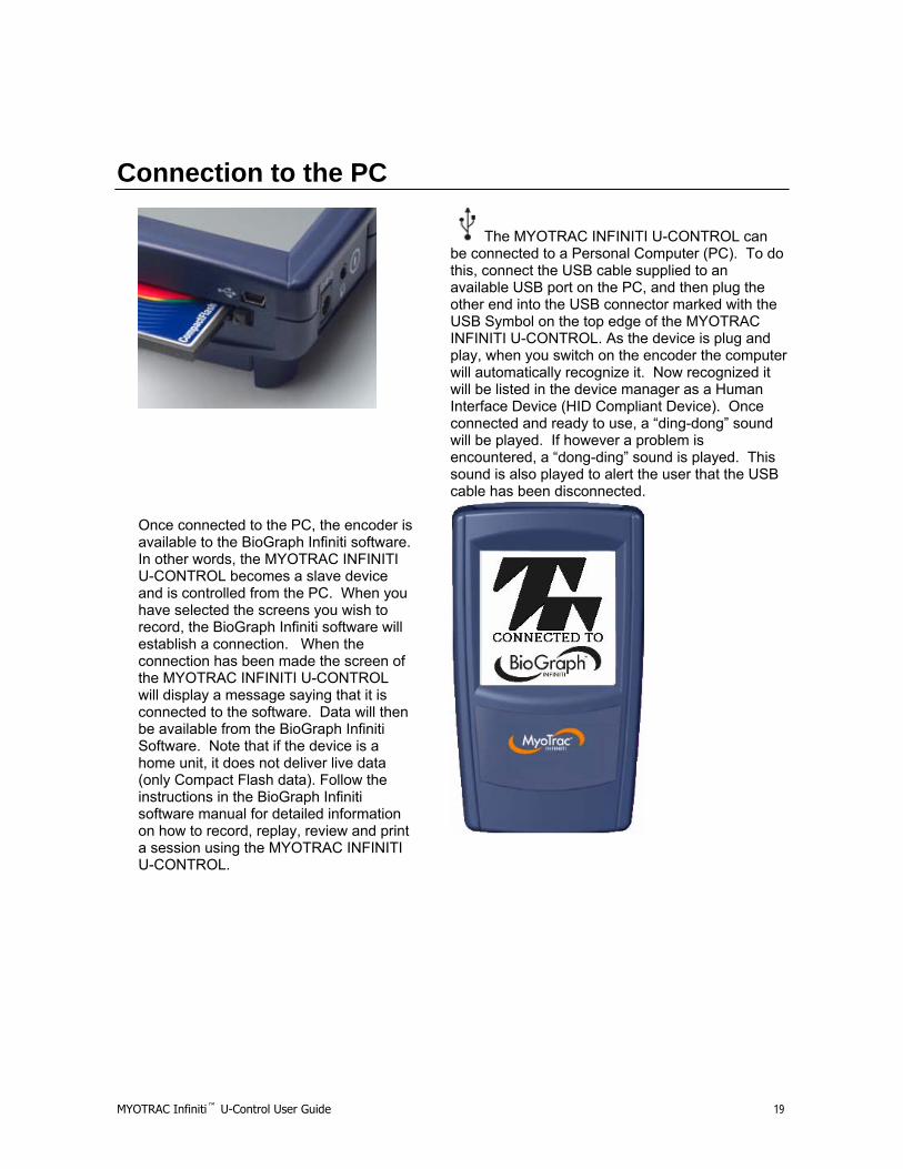
Connection to the PC
The MYOTRAC INFINITI U-CONTROL can be connected to a Personal Computer (PC). To do this, connect the USB cable supplied to an available USB port on the PC, and then plug the other end into the USB connector marked with the USB Symbol on the top edge of the MYOTRAC INFINITI U-CONTROL. As the device is plug and play, when you switch on the encoder the computer will automatically recognize it. Now recognized it will be listed in the device manager as a Human Interface Device (HID Compliant Device). Once connected and ready to use, a “ding-dong” sound will be played. If however a problem is encountered, a “dong-ding” sound is played. This sound is also played to alert the user that the USB cable has been disconnected.
Once connected to the PC, the encoder is available to the BioGraph Infiniti software. In other words, the MYOTRAC INFINITI U-CONTROL becomes a slave device and is controlled from the PC. When you have selected the screens you wish to record, the BioGraph Infiniti software will establish a connection. When the connection has been made the screen of the MYOTRAC INFINITI U-CONTROL will display a message saying that it is connected to the software. Data will then be available from the BioGraph Infiniti Software. Note that if the device is a home unit, it does not deliver live data (only Compact Flash data). Follow the instructions in the BioGraph Infiniti software manual for detailed information on how to record, replay, review and print a session using the MYOTRAC INFINITI U-CONTROL.

MYOTRAC Infiniti™ U-Control User Guide 20
Screen Elements Screens contain up to three element types: • Data displayed in a variety of methods such as line graphs, bar graphs, and digital displays. • Buttons to allow navigation and control of the software. • Thought Support help icon, available in the top left of every screen.
Thought Support Thought Support is a help feature that is available in every screen of the MYOTRAC INFINITI U-CONTROL. To access Thought Support tap the question mark in the top left corner of every screen. This will present you with screen specific assistance explaining the buttons and their functions. Clicking anywhere on the screen when the help is displayed will remove it and return you to the original screen. As a safety feature tapping the question mark during stim will terminate the session that is currently being recorded.

MYOTRAC Infiniti™ U-Control User Guide 21
Settings Menu The settings menu is accessible from the main menu and give you control over the global settings of the MYOTRAC INFINITI U-CONTROL.
Welcome Settings
If not performed when the unit was first switched on the calibration of the screen and the setting of the internal clock can be done from the Settings/Welcome menu. Follow the on screen instructions to make these settings.
Save
The device will automatically set the saving or transferring methods. This screen displays the selected method and gives you the ability to override the default selections. It favors Compact Flash Saving over Internal Memory. Information on the amount of memory used is also displayed in this menu.
Power
Using the power menu it is possible to view the current power settings including the battery level and charging state.
Lock
The lock feature enables you to lock the user interface, limiting the ability to change clinical parameters. This gives you the ability to control the prescribed treatment Script when giving the unit to a client. Using this menu it is possible to then set up the Script that you want to use. Once the Script is selected you set a four-digit pass code to lock the interface. To unlock enter the pass code again. If you inadvertently forget the pass code that you have set, enter 0911 and the encoder will unlock.

MYOTRAC Infiniti™ U-Control User Guide 22
Sound
The sound setting screens allow you to set up the types of sound feedback that the device provides. The three settings that can be modified are Volume, Mini-Pause, and Feedback.
Volume The top-most button (“Volume”) allows for general sound setup. From this screen, the touch sound (heard each time a button has been tapped) can be muted, voice-prompt (heard during scripted sessions) can be disabled and the general volume level can be controlled.

MYOTRAC Infiniti™ U-Control User Guide 23
Mini-Pause Mini-pause is used to monitor the behavior of a patient during regular activity hence enabling the reduction of muscle fatigue. The “Mini-Pause” button allows the user to set up parameters which will alert the user to relax their muscles during an Open SEMG session.
Feedback The “Feedback” button allows you to change the style of sound feedback for each of the two channels independently. The audio feedback corresponds to the EMG signal.
The currently selected feedback option is highlighted in black. You can choose from nine different sound modes:
• No Feedback
• Proportionally Increasing Above Threshold • The higher the EMG signal goes above the set
threshold, the quicker the tone of the audio feedback. • Used for muscle control.
• Proportionally Decreasing Above Threshold • The higher the EMG signal goes above the set
threshold, the slower the tone of the audio feedback. • Used for muscle control.
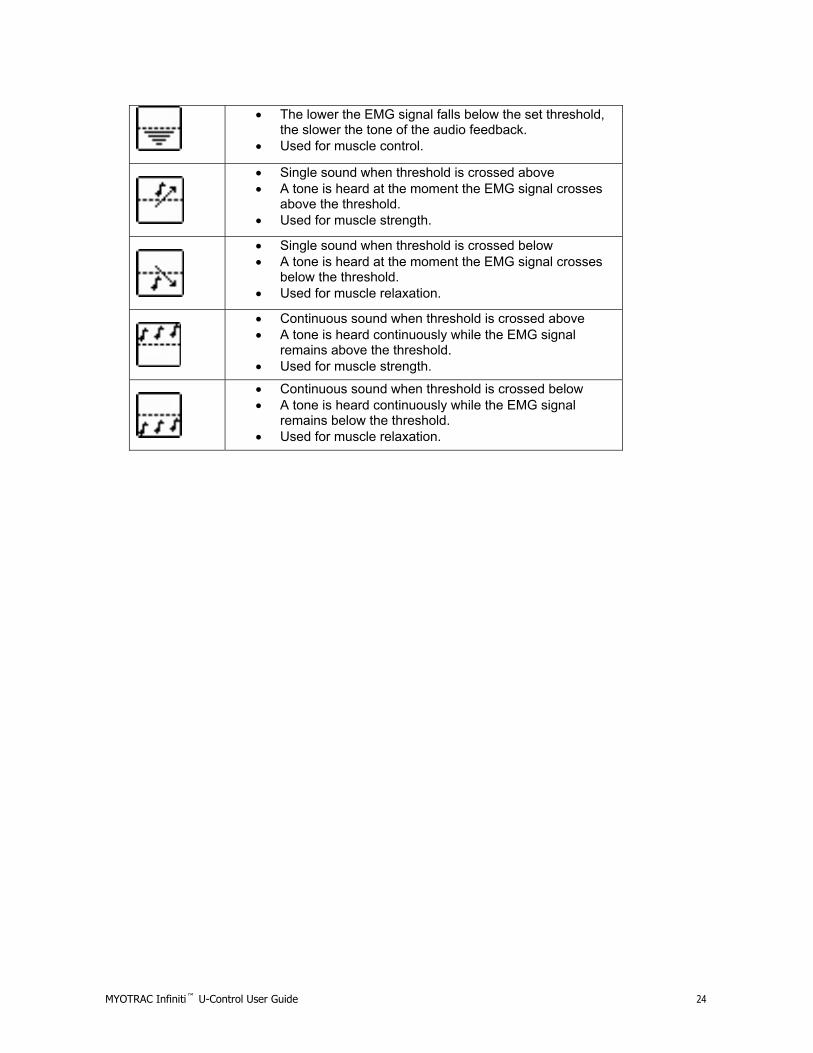
• Proportionally Increasing Below Threshold • The lower the EMG signal falls below the set threshold,
the quicker the tone of the audio feedback. • Used for muscle control.
• Proportionally Decreasing Below Threshold
MYOTRAC Infiniti™ U-Control User Guide 24
• The lower the EMG signal falls below the set threshold, the slower the tone of the audio feedback.
• Used for muscle control.
• Single sound when threshold is crossed above • A tone is heard at the moment the EMG signal crosses
above the threshold. • Used for muscle strength.
• Single sound when threshold is crossed below • A tone is heard at the moment the EMG signal crosses
below the threshold. • Used for muscle relaxation.
• Continuous sound when threshold is crossed above • A tone is heard continuously while the EMG signal
remains above the threshold. • Used for muscle strength.
• Continuous sound when threshold is crossed below • A tone is heard continuously while the EMG signal
remains below the threshold. • Used for muscle relaxation.

MYOTRAC Infiniti™ U-Control User Guide 25
Chapter 2
SEMG sessions on your MYOTRAC INFINITI™ U-CONTROL Encoder What is an SEMG session?
During a Surface Electromyography (SEMG) session, muscle activity is measured and can be recorded by sensing the electrical activity that occurs during muscle contraction and relaxation cycles. Surface Electromyography (SEMG) sessions can be recorded in two formats -Open Sessions or Script Sessions. Recorded data can be saved onto the internal memory of the MyoTrac Infiniti or onto a Compact Flash Card (CF) inserted into the MyoTrac Infiniti, or transferred in real time to the host PC. It is also possible to not save any data and just verify the signal. Open Sessions, also known as free-running sessions, can proceed for an unlimited duration of time without following any set protocols. Different display types (line graph, bar graph and digital display) can be selected to view and/or record the data. Script Sessions, also known as protocol sessions, run for a specified period of time. A script session includes a combination of work, rest, fast flick and/or endurance type exercises. The number of sets for each type and the respective duration has already been determined. The MyoTrac Infiniti has a number of predefined script sessions and furthermore allows for creation of customized script sessions.
Features of an SEMG session
Sound Options: During the free-running portion (before recording begins) of both Open and Script SEMG sessions, the sound options can be modified. Since the Mini-Pause alarm is only activated during an Open session, it is only modifiable during that session. The other sound options are Volume and Feedback. These options are discussed in detail in Chapter 1 -> Settings Menu -> Sound. Auto-Threshold: In a script SEMG session, the Auto-Threshold option is available. This allows for the system, as opposed to the clinician, to determine the threshold value. This means that during the first 3 activities of a session (i.e. work or fast-flick), the threshold that the patient is able to reach is automatically calculated and displayed. The patient must then continue to reach that target throughout the remainder of the session.
Open SEMG Sessions An Open Session can proceed for an unlimited duration of time without following any set protocols. When the user has finished recording the data or verifying the signal, they can simply stop the session by pressing the stop button, the next button, or the back button (depending on whether the session is being recorded or not). SEMG sessions can be viewed using one of three display modes; as visual signals in the line graph and the bar graph or as numeric data using the digital display mode.

MYOTRAC Infiniti™ U-Control User Guide 26
To start an Open SEMG session:
• Select New Open Session from the main menu. • Select Display type (line graph, bar graph or digital display). • Select Client to record this session for (if recording to On-Board Memory or Compact Flash
Card). • Press the Record button having verified the signal (if session is not being saved, then it is just
running). • When the session has been completed tap the Stop button and you will be returned to the
main menu.
MYOTRAC Infiniti™ U-Control User Guide 27
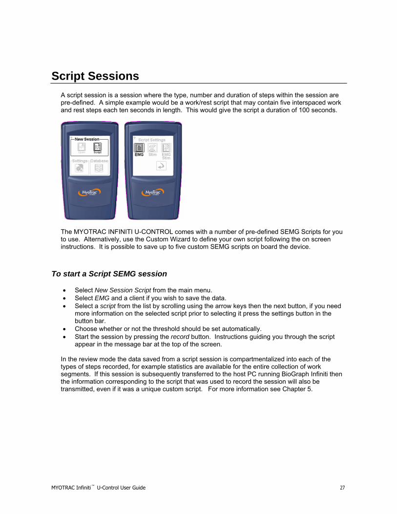
Script Sessions A script session is a session where the type, number and duration of steps within the session are pre-defined. A simple example would be a work/rest script that may contain five interspaced work and rest steps each ten seconds in length. This would give the script a duration of 100 seconds.
The MYOTRAC INFINITI U-CONTROL comes with a number of pre-defined SEMG Scripts for you to use. Alternatively, use the Custom Wizard to define your own script following the on screen instructions. It is possible to save up to five custom SEMG scripts on board the device.
To start a Script SEMG session
• Select New Session Script from the main menu. • Select EMG and a client if you wish to save the data. • Select a script from the list by scrolling using the arrow keys then the next button, if you need
more information on the selected script prior to selecting it press the settings button in the button bar.
• Choose whether or not the threshold should be set automatically. • Start the session by pressing the record button. Instructions guiding you through the script
appear in the message bar at the top of the screen. In the review mode the data saved from a script session is compartmentalized into each of the types of steps recorded, for example statistics are available for the entire collection of work segments. If this session is subsequently transferred to the host PC running BioGraph Infiniti then the information corresponding to the script that was used to record the session will also be transmitted, even if it was a unique custom script. For more information see Chapter 5.

MYOTRAC Infiniti™ U-Control User Guide 28
Chapter 3
STIM sessions on your MYOTRAC INFINITI™ U-CONTROL Encoder What is a Stim session?
A Neuromuscular Electrical Stimulation (NMES) session is used in order to stimulate muscle contraction. During a stim session an electrical impulse is delivered to targeted muscles via electrodes which cause the active motion in the muscles. Stimulation can be run in two formats: Open Sessions or Script Sessions. Data is not recorded during a stimulation session as no EMG is recorded.
Features of a Stim session
Below is a typical waveform for a stimulation pulse. There are a number of variables that can be controlled when running a stimulation session based on your clinical objectives. These can be manually adjusted or a pre-specified set can be selected by using a Script. • Pulse Rate - The rate at which a number of pulses are delivered (URGE, STRESS, MIXED). • Intensity – The intensity in mA that is delivered by each pulse. The maximum available
intensity is 100mA, determined with an input impedance of 500Ω. The maximum intensity that you could use is determined by the electrode size that you are using and may be less than 100mA.
• Ramp – The time it takes for the intensity of successive pulses to reach the preset maximum or back to zero from the start or the end of a series of pulses.
As can be seen from the diagram above of a single stimulation pulse the stim is balanced thus there is no DC component. This means that during stimulation session there is no residual build up of energy at the electrode site. One safety feature of the MYOTRAC INFINITI U-CONTROL is a “client detect”, that detects the connection of the electrodes to the user. If there is not a good electrical connection the unit will not permit the stim to start. Test this periodically by disconnecting the client cable and trying to

MYOTRAC Infiniti™ U-Control User Guide 29
increase the stim intensity. If no stim is felt when the stim is increased, stop use of the unit and contact technical support.
Stimulation for Incontinence Treatment
The MYOTRAC INFINITI U-CONTROL can be used to treat 3 different types of incontinence: stress incontinence, urge incontinence and mixed incontinence. Depending on the type of incontinence, the pulse rate will vary. When setting the current intensity for incontinence it should be noted that the increment step is 0.5mA and stimulation is only possible on one channel.

MYOTRAC Infiniti™ U-Control User Guide 30
Open STIM Session To start an Open Stim session:
• New Open Session from the main menu. • Select U-Stim. • Select the type incontinence to treat. • Confirm Settings to be used during this session by tapping the checkmark. • Start the Stim session: Increase the Stim intensity by using the arrows.
Attention: It is not possible to increase the intensity of the stimulation during the ramps or during the rest phases. It is however possible to decrease during the work or rest phases.

MYOTRAC Infiniti™ U-Control User Guide 31
Stim Settings
The Stim settings menu summarizes the settings for the stimulation session. In the Open Session mode there is a simple structure of work and rest segments to divide the Stim delivery with rest. The Ramp Time is the amount of time it takes the stimulation to ramp up to full intensity at the beginning of the work period and to ramp down at the end of the work period. The pulse rate is the frequency of the individual pulses that go to make up the total stimulation. The pulse width is the duration of each of these individual pulses. To make changes to any of these settings press the edit button on the bottom left of the screen.
Edit Wizard
The edit wizard guides you through each of the parameters that are available for change in the software - Work Rest durations, Ramp Up Time and Ramp Down Time. Once the changes have been made, review them in the Stim settings overview before continuing. Stim intensity is controlled from the stimulation screen.

MYOTRAC Infiniti™ U-Control User Guide 32
Stim Delivery Screen
The Stim delivery screen is the screen that displays the current intensity, maximum intensity and its control. Tap the Start button followed by the up arrows to incrementally control the current being delivered. Current can only be increased during the work period, not during the ramp up or down, or during rest. The current can be decreased during the work or rest, but not the ramps. The maximum current set for the work period is displayed for each channel in the diagram in the middle of the screen. The actual supplied current is shown as the larger numbers at the top of the control arrows. This supplied current reading will display the max mA during work, 0mA during rest and an increasing and deceasing value during the ramps. If you keep your finger on the control buttons it will continue to increase until it reaches the maximum of 100mA. If at anytime you wish to stop the session press the STOP button that covers the top portion of the screen. As a safety feature if the MYOTRAC INFINITI U-CONTROL detects the electrodes being removed while the unit is stimulating, it will automatically stop the Stim. The illustration of the stim cycle in the middle of the screen indicates along with the label at the top of the screen the period of the stim you are currently in. Displayed in the status bar of the stimulation screen is the number of sets done, for an open stimulation setting, or the number remaining for a scripted session.
Script Stim Sessions A script session is a session where the type, number and duration of steps within the session are pre-defined. A simple example would be a work/rest script that may contain five interspaced work and rest steps each ten seconds in length. This would give a script duration of 100 seconds. The work segment of the stim script will deliver stimulation at the preset pulse frequency and duration for a predetermined amount of time, at an intensity that you set.

MYOTRAC Infiniti™ U-Control User Guide 33
The MYOTRAC INFINITI U-CONTROL comes with a number of pre-defined stim scripts for you to use. Alternatively, use the Custom Wizard to define your own script following the on screen instructions. It is possible to save up to five custom Stim scripts on board the device.
To start a Script Stim session:
• Select New Session Script from the main menu. • Select Stim. • Select a Script from the list by scrolling using the arrow keys then the next button. If you need
more information on the selected Script prior to selecting it, press the settings button in the button bar.
• When a Script has been selected, you are taken to the stimulation screen where you start the session by pressing the start button. Instructions guiding you through the Script and a count down of the number of sets appear in the message bar at the top of the screen.
MYOTRAC Infiniti™ U-Control User Guide 34
Chapter 4
EMG-Stim on your MYOTRAC INFINITI™ U-CONTROL Encoder
EMG-Stim Sessions
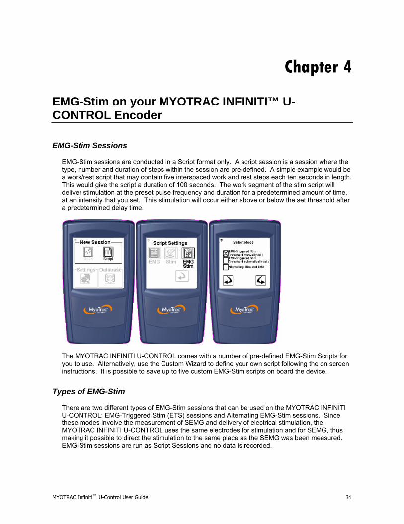
EMG-Stim sessions are conducted in a Script format only. A script session is a session where the type, number and duration of steps within the session are pre-defined. A simple example would be a work/rest script that may contain five interspaced work and rest steps each ten seconds in length. This would give the script a duration of 100 seconds. The work segment of the stim script will deliver stimulation at the preset pulse frequency and duration for a predetermined amount of time, at an intensity that you set. This stimulation will occur either above or below the set threshold after a predetermined delay time.
The MYOTRAC INFINITI U-CONTROL comes with a number of pre-defined EMG-Stim Scripts for you to use. Alternatively, use the Custom Wizard to define your own script following the on screen instructions. It is possible to save up to five custom EMG-Stim scripts on board the device.
Types of EMG-Stim
There are two different types of EMG-Stim sessions that can be used on the MYOTRAC INFINITI U-CONTROL: EMG-Triggered Stim (ETS) sessions and Alternating EMG-Stim sessions. Since these modes involve the measurement of SEMG and delivery of electrical stimulation, the MYOTRAC INFINITI U-CONTROL uses the same electrodes for stimulation and for SEMG, thus making it possible to direct the stimulation to the same place as the SEMG was been measured. EMG-Stim sessions are run as Script Sessions and no data is recorded.

MYOTRAC Infiniti™ U-Control User Guide 35
What is an EMG triggered Stim session?
An SEMG triggered Stim session is the combination of the two complementary modalities to form a third treatment possibility. The client’s own volitionally activated SEMG is used as a guide to determine when to automatically stimulate. This combination of passive and active rehabilitation elements could be considered as getting the best of both worlds.
Features of an EMG triggered Stim session
Trigger Modes: Depending on the context, stimulation can occur either when crossing above threshold or when the signal falls below the threshold. When the trigger is above threshold, it can be referred to as “reward” mode. When the target threshold has been reached, an electrical impulse is delivered to the patient in order to complete the contraction. This mode motivates the patient and involves them in the rehabilitation process. When the trigger is set to activate below threshold, it can be referred to as “assistance” mode. When the patient is unable to hold the contraction for a long enough duration using this mode will assist them in finishing the contraction. The trigger mode can be set when customizing a script session. In the case of a predefined script session the trigger mode is already selected and can be verified by checking the script information. Threshold Modes: This threshold can be set either by the user (manual) or by the system itself (automatic). Automatic threshold mode is different for trigger above threshold and trigger below threshold. When the stimulation is triggered below threshold, then during the first 3 activities of a session (i.e. work or fast-flick), the threshold that the patient is able to reach is automatically calculated and displayed. The patient must then continue to reach that target throughout the remainder of the session. When stimulation is triggered above the threshold then the threshold will be adjusted throughout the session.
Script Structure
SEMG triggered Stim sessions are conducted in a Script format. A Script takes the form of a number of work and rest steps. During a work step, the MYOTRAC INFINITI U-CONTROL will guide the client to activate the muscle being monitored. In addition to the signal displayed on the graph we can also see the trigger threshold defined at setup time. If during the work period the signal reaches the trigger threshold for a time greater than the pre-determined delay period, then the stimulation is triggered. This stimulation is delivered for the remainder of the work step. The rest step is just that, it is a period of time where the client rests following a period of activation of the muscle being monitored. During the rest period it is not possible to stimulate, and the threshold trigger is ignored. The illustration below shows a Script of 20 second work and rest steps, with a threshold set to 40uV and a delay of 5 seconds on a positive crossing trigger. It shows two work segments: one where the stimulation is not triggered, the other when it is.

MYOTRAC Infiniti™ U-Control User Guide 36
What is an Alternating EMG-Stim session?
An Alternating EMG-Stim session is a repeated sequence of Stim and EMG. It is not the same thing as an EMG triggered Stim session. In this mode the Stim occurs during the rest period and it is used in order to make the patient understand what the muscle contraction should feel like. During the work period, the patient will need to reproduce the contraction achieved during the previous stim session. This combination of stimulation and reiterative behavior can strengthen the muscles and help the patient relearn the natural reflexes.
Features of an Alternating EMG-Stim session
Threshold Mode: For Alternating EMG-Stim sessions, automatic threshold mode is used to determine the value of the threshold. This works in the same was as for script SEMG sessions. Auto-threshold mode allows for the system, as opposed to the clinician, to determine the threshold value. This means that during the first 3 activities of a session (i.e. work or fast-flick), the threshold that the patient is able to reach is automatically calculated and displayed. The patient must then continue to reach that target throughout the remainder of the session.
Script Structure
Alternating EMG-Stim sessions are conducted in a Script format. A Script takes the form of a number of work and rest steps. During a work step, the MYOTRAC INFINITI U-CONTROL will deliver an electrical impulse to the muscle being monitored. This stimulation will cause the muscle to contract. During the rest step, the patient will volitionally contract their muscle in a manner similar to what was felt when the electrical impulse was delivered during the previous work step. In this case the threshold acts solely as a target that the patient must reach. The illustration below shows a Script of 20 second work and rest steps, with a threshold set to 40uV. It shows three rest segments and two work segments: during each of the work segments, muscle contractions similar to the stim-induced ones occur.

MYOTRAC Infiniti™ U-Control User Guide 37
To run an EMG-Stim Script select:
• New Script Session from the main menu. • Select EMG-Stim • Select the the threshold mode
o EMG-Triggered Stim (threshold manually set) o EMG-Triggered Stim (threshold automatically set) o Alternating Stim and EMG
• Select Script by using the up, down and forward arrows. A number of pre-defined Scripts are available or you can design your own using the custom design Wizard, covered later in the chapter.
• Threshold Setting: Confirm or change the threshold that will be used to determine if the stimulation should be triggered.
• Set Stim Intensity: The intensity that is set here will be delivered if the correct criteria are met in the recording phase. Use the up and down arrows to set the intensity. When this is set move forward to the recording screen.
• Start the EMG Triggered Stim session: Start the Script driven session by tapping the record button. To stop the session tap this button again, or, during the Stim delivery, press the stop button.
MYOTRAC Infiniti™ U-Control User Guide 38
Chapter 5
Data Management on your MYOTRAC INFINITI™ U-CONTROL Encoder
This chapter explains how to manipulate the data that you have recorded to the MYOTRAC INFINITI U-CONTROL for a number of clients and how to interface this data with the BioGraph Infiniti on the host PC.
What is Data Management?
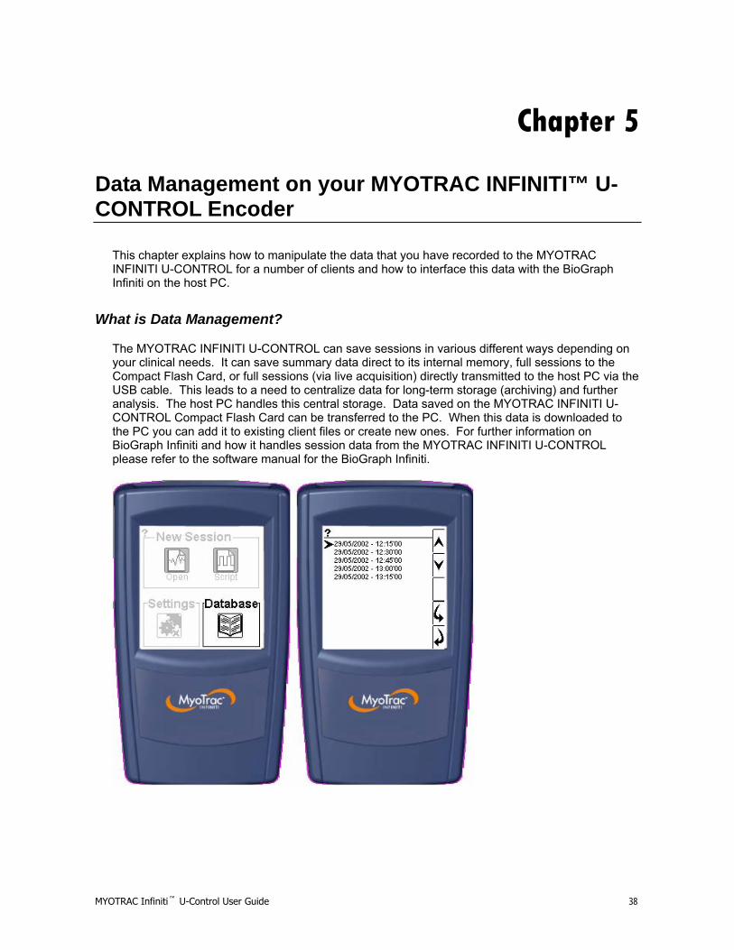
The MYOTRAC INFINITI U-CONTROL can save sessions in various different ways depending on your clinical needs. It can save summary data direct to its internal memory, full sessions to the Compact Flash Card, or full sessions (via live acquisition) directly transmitted to the host PC via the USB cable. This leads to a need to centralize data for long-term storage (archiving) and further analysis. The host PC handles this central storage. Data saved on the MYOTRAC INFINITI U-CONTROL Compact Flash Card can be transferred to the PC. When this data is downloaded to the PC you can add it to existing client files or create new ones. For further information on BioGraph Infiniti and how it handles session data from the MYOTRAC INFINITI U-CONTROL please refer to the software manual for the BioGraph Infiniti.

MYOTRAC Infiniti™ U-Control User Guide 39
MYOTRAC INFINITI U-CONTROL Review Data can also be reviewed on the MYOTRAC INFINITI U-CONTROL as a stand alone piece of equipment. It is possible to view the summary statistics or replay the session in either of the three display types. To access the data tap the Database button on the main menu. This will present you with the saved sessions listed in order of date. Use the up and down arrows to scroll between sessions. When you have selected the session that you are interested in, use the forward arrow to view it. Once you have selected the data session that you wish to manage you are presented with the summary screen. This screen gives you information on when the session was recorded and for which client. As you can see in the illustration below there are three choices. • Replay – When selecting to replay a session it gives you further information on the recorded
Script and asks if you wish to replay it in the same screen type or change between the line graph, or bar graph. This feature is only available if the session was saved to the compact flash card.
• Session Statistics – The session statistics comprise the whole session. If the session was recorded in a Script it breaks down the data into step type statistics (work, rest, flick and endurance).
• Internal Session Delete – This feature enables you to permanently remove sessions that have been recorded on the internal memory. The session saved to the CF card can only be removed by using the BioGraph Infiniti Software.
MYOTRAC Infiniti™ U-Control User Guide 40
Chapter 6
Display Options on your MYOTRAC INFINITI™ U-CONTROL Encoder
In this chapter we will take a closer look at each of the three major display types with which to view SEMG data.
Displays When recording an SEMG session, there are three types of data display available: Line Graph, Bar Graph, and Digital Display.
Line Graph
The line graph display is a good choice if the signal is time dependant, and a history of the signal is required. It is the most comprehensive of the display choices, showing in real time up to two signals on a single set of axis. Some of the key features of the line graph are the thresholds, gain and sweep controls.
Bar Graph
The bar graph display is designed to give a clear indication of the relative levels of each channel. It can also be used in ratio mode to give information on the interplay of the two channels.
Digital Display
The digital display consists of two pages of numerical information computed from the two channels. It is possible to change the automatic refreshing rate of the data displayed or to refresh manually.

MYOTRAC Infiniti™ U-Control User Guide 41
Line Graph
• Record/Stop – When you initially move into the line graph screen the trace will appear on the
screen to allow you to confirm electrode placements and signals. To start the recording, press on the circle. It will change to a square. To stop the recording press it once again. During the recording, the word REC will flash in the status bar at the top of the screen.
• Gain/Sweep – Expand or contract the X or Y axis scale to view the signal as the scale that you want. When you tap on the gain and sweep button a sub menu appears. Use the first button on the sub menu to select the Y or X axis to change. The second button on the sub menu puts change focus on either the top digit or the bottom digit of the axis selected. The + and – buttons increase or decrease the selected values.
• Threshold – The threshold settings allow you to set a threshold for feedback. When you tap on the threshold button you are presented with a sub menu. The first button on the sub menu is used to select a threshold for Channel (A) or (B). With either A or B selected, use the + and – buttons to move the position of the threshold up or down on the range. The button below depicts an eye either open or closed. This is used to show or hide the selected threshold.
• Line Display – This button enables you to select whether Channel A should be filled or unfilled. Here you can also decide to show or hide the signal for each of the channels.
• X and Y axis – Scales settings currently selected via the gain/sweep button. • Thought Support Help – Screen specific help. If you are not sure about the icons, this will
show you the way. • Ch A/B Legend – This is the legend for describing which line styles and displays the settings
from the line style button. • Thought Support Help – Screen specific help. If you are not sure about the icons, this will
help. • Sound Enabled – Use this button to disable the sound feedback being given in this screen.
Speaker symbol has a cross through it if the sound is disabled. Before the recording begins, this button is also used to modify the sound settings (volume, mini-pause, if available and audio feedback).
MYOTRAC Infiniti™ U-Control User Guide 42
Bar Graph
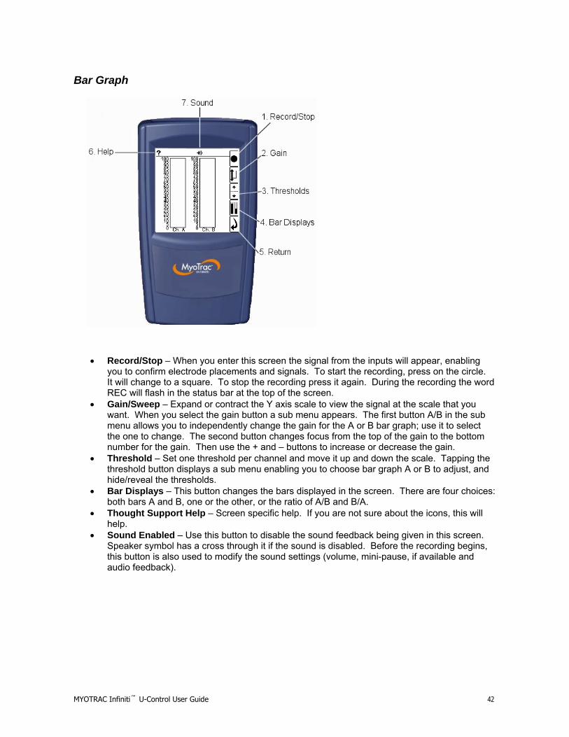
• Record/Stop – When you enter this screen the signal from the inputs will appear, enabling you to confirm electrode placements and signals. To start the recording, press on the circle. It will change to a square. To stop the recording press it again. During the recording the word REC will flash in the status bar at the top of the screen.
• Gain/Sweep – Expand or contract the Y axis scale to view the signal at the scale that you want. When you select the gain button a sub menu appears. The first button A/B in the sub menu allows you to independently change the gain for the A or B bar graph; use it to select the one to change. The second button changes focus from the top of the gain to the bottom number for the gain. Then use the + and – buttons to increase or decrease the gain.
• Threshold – Set one threshold per channel and move it up and down the scale. Tapping the threshold button displays a sub menu enabling you to choose bar graph A or B to adjust, and hide/reveal the thresholds.
• Bar Displays – This button changes the bars displayed in the screen. There are four choices: both bars A and B, one or the other, or the ratio of A/B and B/A.
• Thought Support Help – Screen specific help. If you are not sure about the icons, this will help.
• Sound Enabled – Use this button to disable the sound feedback being given in this screen. Speaker symbol has a cross through it if the sound is disabled. Before the recording begins, this button is also used to modify the sound settings (volume, mini-pause, if available and audio feedback).
MYOTRAC Infiniti™ U-Control User Guide 43
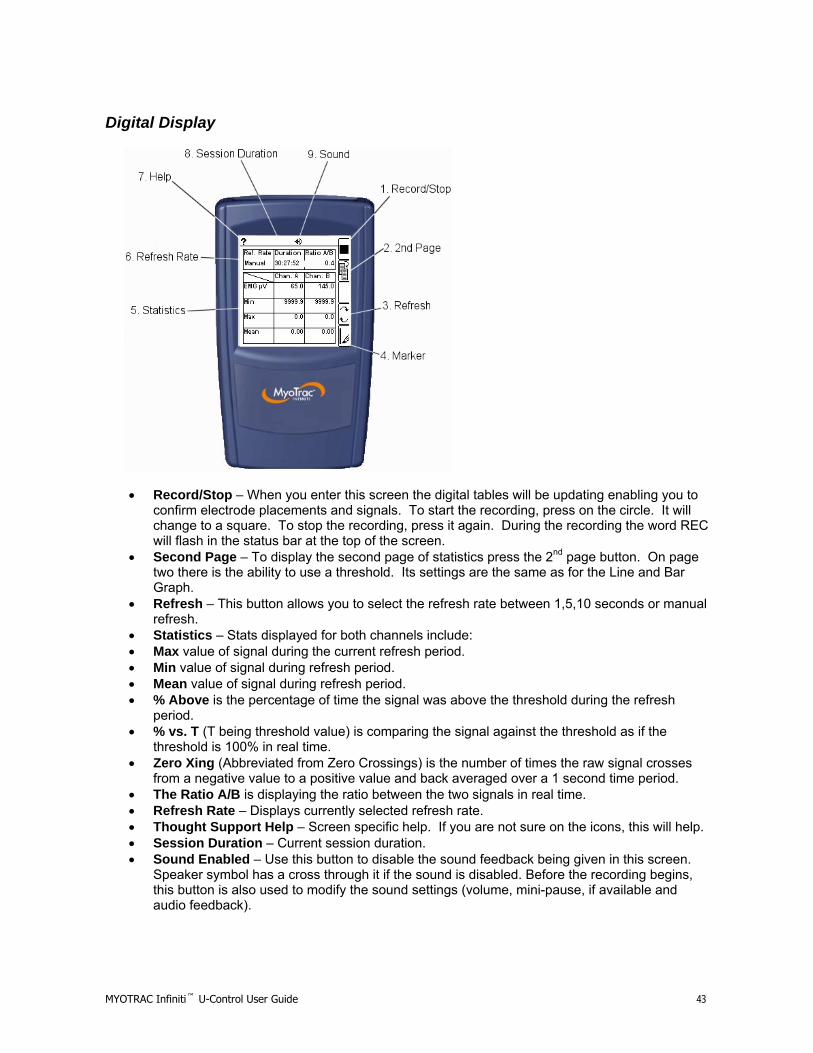
Digital Display
• Record/Stop – When you enter this screen the digital tables will be updating enabling you to
confirm electrode placements and signals. To start the recording, press on the circle. It will change to a square. To stop the recording, press it again. During the recording the word REC will flash in the status bar at the top of the screen.
• Second Page – To display the second page of statistics press the 2nd page button. On page two there is the ability to use a threshold. Its settings are the same as for the Line and Bar Graph.
• Refresh – This button allows you to select the refresh rate between 1,5,10 seconds or manual refresh.
• Statistics – Stats displayed for both channels include: • Max value of signal during the current refresh period. • Min value of signal during refresh period. • Mean value of signal during refresh period. • % Above is the percentage of time the signal was above the threshold during the refresh
period. • % vs. T (T being threshold value) is comparing the signal against the threshold as if the
threshold is 100% in real time. • Zero Xing (Abbreviated from Zero Crossings) is the number of times the raw signal crosses
from a negative value to a positive value and back averaged over a 1 second time period. • The Ratio A/B is displaying the ratio between the two signals in real time. • Refresh Rate – Displays currently selected refresh rate. • Thought Support Help – Screen specific help. If you are not sure on the icons, this will help. • Session Duration – Current session duration. • Sound Enabled – Use this button to disable the sound feedback being given in this screen.
Speaker symbol has a cross through it if the sound is disabled. Before the recording begins, this button is also used to modify the sound settings (volume, mini-pause, if available and audio feedback).

MYOTRAC Infiniti™ U-Control User Guide 44
Chapter 7
Flow on your MYOTRAC INFINITI™ U-CONTROL Encoder
New Open Session

MYOTRAC Infiniti™ U-Control User Guide 45
Chapter 8 Reference
Glossary of Terms, Abbreviations and Symbols
PC Personal Computer SEMG Surface Electromyography STIM Stimulation Stylus A blunt pointed object used to tap the screen. CF Compact Flash T Template A Channel A B Channel B REC Record -ve Negative +ve Positive Scripts Session A Script is a sequence of events in a pre-determined session duration. Open Session An open session is defined on the fly by the clinician. Its length is governed by
the Record and Stop buttons. Zero X-ing (Zero Crossings)
Then number of times the raw signal crosses from positive to negative or the reverse.
USB connector

MYOTRAC Infiniti™ U-Control User Guide 46
Technical Support and Order Placing Returning Equipment
Be sure to call for an authorization number (RA) before returning any equipment!
Send the unit(s) postage prepaid and insured, with proof of purchase to one of the addresses below. If you are shipping from outside Canada or the USA to Canada, mark the package ‘Goods to be repaired - Made in Canada’ to avoid unnecessary customs charges. All customs and duties charges will be billed to you if incurred by sending the unit to the wrong address. Provide a detailed description of the problem you are experiencing, and your telephone/fax number and email (see form on the last page of this manual). In the USA, ship insured to: Thought Technology Ltd. Cimetra Industrial Park 8396 Route 9 West Chazy, New York 12992-2718, USA In Canada and all other countries, contact your dealer or ship insured to: Thought Technology Ltd. 2180 Belgrave Avenue Montreal, Quebec Canada H4A 2L8
Technical Support For technical support please refer to the Thought Technology Ltd website at www.thoughttechnology.com for frequently asked questions. If your support issue is not covered please e-mail or telephone at the number below. (514) 489-8251 [email protected] Fax (514) 489 8255

MYOTRAC Infiniti™ U-Control User Guide 47
Product Numbers & Accessories MYOTRAC INFINITI U-CONTROL ENCODER & SENSORS
SA9570/ SA9571 ST CLOUD SENSOR SA9572 PHYSIOMED VAGINAL SENSOR SA9800 MYOTRAC INFINITI T6050 TTL INCONTINENCE SENSOR VAGINAL T6051 TTL INCONTINENCE SENSOR RECTALSA9305 EEG SENSOR T7900 BIOGRAPH INFINITI SOFTWARE
ACCESSORIES
MI0009-00 4 X AAA BATTERIES MI1028 BATTERY PACK MI1031 INFINITI CASE MI1050 Rechargeable Battery Pack SA3403 ELECTRODE EXTENDER CABLES (THREE PACK) SA5000-14 AQUASENSE SMALL ARM PROTECTOR SA5000-16 AQUASENSE MEDIUM ARM PROTECTOR SA5000-18 AQUASENSE LARGE ARM PROTECTOR SA5010-14 AQUASENSE SMALL LEG PROTECTOR SA5010-16 AQUASENSE MEDIUM LEG PROTECTOR SA5010-18 AQUASENSE LARGE LEG PROTECTOR SA7713 USB CABLE 1.8M SA9801 Sensor DIN Adaptor Cable SA9804/06/11 STIMULATION ELECTRODES SA9813 MYOTRAC INFINITI USER GUIDE T3402M TRIODE DISPOSABLE ADHESIVE ELECTRODES (X 100) T3404 SINGLE DISPOSABLE ELECTRODES (X 300) T3425 UNI-GEL ELECTRODES (X 100) T8720M SENSOR EXTENDER CABLE (PROTECTED PIN) T9385M SENSOR REPLACEMENT CABLE KIT
SA2306 HEADBAND EMG SA8740 DIN CABLES T3470 NU-PREP GEL T3450 10-20 PASTE

MYOTRAC Infiniti™ U-Control User Guide 48
Placing Orders
Outside USA Tel: (514) 489-8251 Fax: (514) 489-8255 In USA Toll-Free Tel: 1-800-361-3651 E-Mail: [email protected]

MYOTRAC Infiniti™ U-Control User Guide 49
Specifications
MyoScan EMG Sensor (SA9503M)
Size (Approx.) 37mm x 37mm x 12mm (1.45” x 1.45” x 0.45”)
Weight 15g (0.5 oz)
Input Impedance ≥1012Ω in parallel with 10pF
Input Range 0 – 2000μVRMS
Sensitivity <0.1μVRMS
CMRR >130dB
Channel Bandwidth 10Hz – 1kHz
Signal Output Range 0 – 1.0V RMS
Input / Output Gain 500
Supply Voltage 7.26V (± 0.02V)
Current Consumption 0.7mA (± 0.25mA)
Accuracy ±0.3μVRMS Plus ±4% of reading @25°C to 30°C,
MYOTRAC Infiniti Encoder (SA9800)
Size (approx.) 102mm x 152mm x 51mm (4” x 6” x 2”)
Weight (approx.) 330 g (11oz) with Batteries
Power Source 4AAA batteries, single use alkaline or Rechargeable battery pack 6V Medical Grade AC wall adaptor 5V USB
Battery Life, Alkaline cells (1200mAh) 3 – 4h typical
Battery Life, Battery Pack (700mAh) 3 – 4h typical
Low-battery warning Before shut down
ADC output 14bits
Encoder sample rate 2048 samples/second nominal
Encoder channel bandwidth (3dB) Internal EMG amplifier External Sensor Input
20 – 500Hz DC – 500Hz
Anti-aliasing Filter 4th order Butterworth -3dB at 500Hz
Alias rejection 24 dB typical
Gain accuracy ±0.5 %
Accuracy including external sensor ± 5 % +0.6μV RMS
STIM SETTINGS VALID BETWEEN 500Ω to 1kΩ load impedance.
Stimulation intensity 0mA – 100mA

MYOTRAC Infiniti™ U-Control User Guide 50
Stimulation Pulse Rate 12.5Hz, 20Hz, 50Hz
Pulse Width 200μs
Ramp Time ( Up and Down ) 0 – 10 sec
NOTE: MYOTRAC INFINITI and its sensors are sensitive electronic instruments and should be handled as such. Be especially careful to avoid both pulling on the electrode cable and getting moisture or electrode gel on the sensor snaps. If necessary, wipe the surface with a damp cloth or use a moistened Q-tip to remove gel from inside the sensor snaps. Wipe with a dry cloth.
MYOTRAC Infiniti™ U-Control User Guide 51
Warranty The MYOTRAC INFINITI system and all equipment including optional items are guaranteed to be free from defects in material and workmanship for 1 year from the date of purchase. In the unlikely event that repair is necessary, call Thought Technology Ltd. to receive a Return Authorization. Then send the unit back by a traceable method--Thought Technology will not be responsible for items not received. We will repair or replace your unit(s) free of charge. This warranty does not apply to damage incurred through accident, alteration, or abuse, nor to sensor damage created by static electricity, or to screen damage resulting from misuse. Do not use this equipment in dry, static area unless using an anti-static mat or anti-static spray on carpeted areas. IMPORTANT: Remove dead batteries promptly to prevent corrosion damage.
Optional Extended Warranty Please contact Thought Technology Ltd. for further details.

MYOTRAC Infiniti™ U-Control User Guide 52
Repair Return Form
Be sure to call for authorization before returning any equipment! Remove or copy this form and include it with the unit(s). Include copy of original invoice and return to the address in the Returning Equipment section.
Name
Company
Address
Phone No.
Fax No.
Date Purchased
From Whom
Model Name
Serial Number
Problem

MYOTRAC Infiniti™ U-Control User Guide 53
MYOTRAC Infiniti Hardware Copyright Notice
This hardware contains proprietary embedded software code, which is the property of Thought Technology Ltd.; it is provided under a license agreement containing restrictions on use and disclosure and is also protected by copyright law. Reverse engineering of the software or the resulting output data stream is prohibited. Due to continued product development the embedded software may change without notice. The information and intellectual property contained herein is confidential between Thought Technology Ltd. and the client and remains the exclusive property of Thought Technology Ltd. If you find any problems in the documentation, please report them to us in writing. Thought Technology Ltd. does not warrant that this document is error-free. No part of this publication may be reproduced, stored in a retrieval system, or transmitted in any form or by any means, electronic, mechanical, photocopying, and recording or otherwise without the prior written permission of Thought Technology Ltd. MYOTRAC-Infiniti™, BioGraph Infiniti™ are trademarks of Thought Technology Ltd. © Copyright Thought Technology 2005