u. s. department of the interior - bureau of reclamation · u. s. department of the interior bureau...
TRANSCRIPT

REC-ERC-84-21
February 1985
Engineering and Research Center
U. S. Department of the Interior Bureau of Reclamation

7-2090 (4-81) Bureau of Reclamation TECHNICAL RE
4. TITLE AND SUBTITLE
Applications Development of Concrete Polymer Materials- A Summary Report
7. AUTHOR(s)
Carl E. Selander
9. PERFORMING ORGANIZATION NAME AND ADDRESS
Bureau of Reclamation Engineering and Research Center Denver, CO 80225
12. SPONSORING AGENCY NAME AND ADDRESS
15. SUPPLEMENTARY NOTES
:runl SIANUAHU IliLt rAtit 3. RECIPIENT’S CATALOG NO.
5. REPORT DATE
February 1985 6. PERFORMING ORGANIZATION CODE
D-1510
6. PERFORMING ORGANIZATION REPORT NO.
REC-ERC-84-21
10. WORK UNIT NO.
11. CONTRACT OR GRANT NO.
3-PT-81-29540 13. TYPE OF REPORT AND PERIOD
COVERED
14. SPONSORING AGENCY CODE
DIBR
Microfiche and/or hard copy available at the Engineering and Research Center, Denver, Colorado
Editor: REC(c)
16. ABSTRACT
This report summarizes the work accomplished under PRESS Project No. DR-381, Appli- cations Development of Concrete Polymer Materials, from FY75 through FY83. Individual program studies are identified in the section entitled “Program Summary” under the fiscal year the work was undertaken. Many of the studies continued for a number of years. Several were performed at a single site. Each project is discussed in greater detail in the section entitled “Project Summaries.”
17. KEY WORDS AND DOCUMENT ANALYSIS
o. DESCRIPJORS-- acrylic polymer concretes/ epoxy mortar/ vinyl ester resin/ *polymer concrete/ “polymer-impregnated concrete/ “concrete polymer materials/ polymerization/ monomers/ concrete products/ concrete repair materials/ concrete paver/ polymer-impreg- nated asbestos cement/ polymer shotcrete/ methacrylic polymer concretes
b. IDEN JIFIERS-- Shadow Mountain Dam/ Madera Canal/ Grand Coulee Dam/ San Juan- Chama Project/ Azotea Tunnel/ Blanc0 Tunnel
c. COSAJI Field/Group13C COWRR: 1303.1 SRIM:
16. DISTRIBUTION STATEMENT 19. SECURITY CLASS 21. NO. OF PAGE
Available from the Notional Technical Information Service, Operations (THIS REPORT)
102 Division, 5285 Port Royal Road, Springfield, Virginia 22161. UNCLASSIFIED
20. SECURITY CLASS 22. PRICE
(Microfiche and/or hard copy available from NTIS) (THIS PAGE)
UNCLASSIFIED

REC-ERC-84-21
APPLICATIONS DEVELOPMENT OF CONCRETE POLYMER MATERIALS- A SUMMARY REPORT
by Carl E. Selander Prepared under Contract No. 3-PT-81-29540
February 1985
Concrete and Structural Branch Division of Research and Laboratory Services Engineering and Research Center Denver, Colorado
SI METRIC
UNITED STATES DEPARTMENT OF THE INTERIOR * BUREAU OF RECLAMATION

ACKNOWLEDGMENTS
Recognition is given to the three principal investigators involved in this study: in sequence, H. C. Riffle, M. C. Redmond, and W. G. Smoak; and to their immediate unit supervisors, W. C. Cowan, C. A. Nelson, and G. W. DePuy, respectively. The pro- gram was directed by C. E. Selander, the Head, Polymer Con- crete and Structural Section, from July 1974 through January 1983, and by G. W. DePuy (the Acting Head), from February through October 1983.
Recognition is also given to the staff of the Polymer Concrete and Structural Section and to others, too numerous to mention, who participated in the many field studies. Special recognition is given to F. E. Causey and D. 0 Arney, who were involved in every project in the program.
As the Nation’s principal conservation agency, the Department of the Interior has responsibility for most of our nationally owned public lands and natural resources. This includes fostering the wisest use of our land and water resources, protecting our fish and wildlife, preserv- ing the environmental and cultural values of our nationat parks and historical places, and providing for the enjoyment of life through out- door recreation. The Department assesses our energy and mineral resources and works to assure that their development is in the best interests of all our people. The Department also has a major respon- sibility for American Indian reservation communities and for people who live in Island Territories under U.S. Administration.
The research covered by this report was funded under the Bu- reau of Reclamation Program Related Engineering and Scientific Studies allocation No. DR-381, Applications Development of Concrete Polymer Materials.
1 I
The information contained in this report was developed for the Bureau of Reclamation; no warranty as to the accuracy, usefulness, or com- pleteness is expressed or implied.

q;"Q)
.~~eIJ;:
.g~~u..:uQ)
.""e0.:5~0~0)
~
I
.g~~Q)
...CQ
..J~~~Q.S~§~~.g~


CONTENTS
introduction . . . . . . . . . . . . . . . . . . . . . . . . . . . . . . . . . . . . . . . . . . . . . . . . . . . . . . . . . . . . . . . . . . . . . . . . . . . . . . . . . . . . . . . . . . . . . . . . . . . . . . . ,... . . . . . . . . . . . . . . . . . . . . . .
Conclusions . . . . . . . . . . . . . . . . . . . . . . . . . . . . . . . . . . . . . . . . . . . . . . . . . . . . . . . . . . . . . . . . . . . . . . . . . . . . . . . . . . . . . . . . . . . . . . . . . . . . . . . . . . . . . . . . . . . . . . . . ........
Program summary ....................................................................................................................... FY75 Program summary.. ......................................................................................................... FY75 transition quarter and FY76 program summary.. ................................................................ FY77 Program summary ........................................................................................................... FY 78 Program summary ........................................................................................................... FY 79 Program summary ........................................................................................................... FY80 Program summary ........................................................................................................... FY 8 1 Program summary ........................................................................................................... FY82 Program summary ........................................................................................................... FY83 Program summary ...........................................................................................................
Project Summaries ....................................................................................................................... CHO (constant head orifice) turnouts, FY75-FY83.. ..................................................................... Geothermal Well Test Facility field tests, FY75-76.. .................................................................... Shadow Mountain Dam, Colorado-Big Thompson Project field tests, FY74-FY83.. ........................ Shape study, FY77.. ................................................................................................................. San Juan-Chama Project field tests, FY75 transition quarter FY80.. ............................................. Madera Canal, Central Valley Project, FY76-FY83.. ..................................................................... Grand Coulee Dam, Columbia Basin Project, FY79-FY83 ............................................................. Demonstrations at various projects, FY79-FY83.. ....................................................................... Spring Creek Debris Dam, Trinity River Division, Central Valley project, FY80-FY81....................... DFC sidewalk overlay tests, FY77, FY79-FY82 .......................................................................... Oklahoma bridge overlay, FY 82-FY83 ........................................................................................ Roundrobin inspection of bridges, FY83 .....................................................................................
Bibliography . . . . . . . . . . . . . . . . . , . . . . . . . . . . . . . . . . . . . . . . . . . . . . . . . . . . . . . . . . . . . . . . . . . . . . . _. . . . . . . . . . . . . . . . . . . . . . . . . . . . . . . . . . . . . . . . . . . . . . . . . . . . . . . . 30
APPENDIXES
A - Polymer Impregnation of Constant Head Orifice Turnouts for Grand Coulee Dam, Columbia Basin Project ................................................................................................................................
B - Progress Report for FY75-76, Polymer Applications, DR-381 ..................................................
C - impregnation of Pipe for Geothermal Wells ............................................................................
D - Experimental Repair of Shadow Mountain Dam Spillway.. ........................................................
TABLES
Table Page
1 Allowable stresses and material properties for PIC CHO used in the Wahluke Branch Canal Laterals ....................................................................................
2 PC mix design data for test slabs at the Geothermal Well Test Facility ............................... 3 Core tests of polymer penetrations into the spillway floor at Shadow Mountain Dam ......... 4 Mix PC 285 - 7 percent VE mix with F-95 Ottawa sand, silica, and polymer powder.. ......... 5 Ratios (Y/x) of average compressive strengths at various shapes and sizes of polymer
concrete specimens .................................................................................................... 6 Composition of the polymer concrete used at Blanc0 Tunnel .............................................
Mix design data for experimental VE PC for Madera Canal drop structure ........................... Mix design data for the thin polymer overlay used at Grand Coulee Dam ............................
Page
1
1
4 4
ii 17 17
:: 25 27 28 29 30
33
49
63 81
4 6
14 15
18 20 21 25
V

Figure FIGURES
Page
7
! 10 11 12 13 14
15 16
17
18 19
E 22
23 24
25 26
27
28
Back and side view of assembled PIC CHO.. ..................................................................... Front (canal-side) view of assembled PIC CHO .................................................................. Installation of the PIC CHO in the Wahluke Branch Canal Laterals ....................................... Bypass No. 3 with PIC and PIAC test sections under construction ..................................... End of bypass No. 1 pipe discharging waste steam .......................................................... Schematic layout for experimental repairs on the floor of the
Shadow Mountain Dam spillway .................................................................................. Enclosure used for drying and for polymerization of impregnated monomer
in the surface impregnation process during the drying cycle.. ......................................... Application of the vinyl ester PC overlay on the concrete surface.. ..................................... Concrete paving machine finishing the VE PC overlay during the first field trial .................... Pattern cracking in the VE PC overlay examined by research and field personnel.. ............... Cleaning the concrete surface with commercial shot blast equipment.. ............................... The first enclosure, during the cooling cycle of the surface impregnation process ............... The second enclosure, with aluminum covers on the roofing ............................................. Deep holes in the surface were filled with VE PC and finished with a
vibrating screed prior to the overlay application ............................................................ The paving machine applying the VE PC overlay on the first pass ...................................... Acrylic PC was mixed in a conventional concrete mixer and placed,
screeded, and finished by hand troweling.. ................................................................... Field application of VE polymer shotcrete to baffle blocks at the
outlet of Atotea Tunnel.. ............................................................................................. Hand placing and finishing the VE PC at Blanc0 Tunnel ...................................................... The first field application of VE PC, made on the steep slope of a
drop structure on the Madera Canal ............................................................................. Trial application of low-viscosity VE polymer shotcrete ..................................................... Application of an acrylic PC on a drop structure of the Madera Canal.. ............................... The fully resurfaced floor of the Madera Canal drop structure,
before application of a smoothing top coat.. ................................................................. Screeding one of the trial PC materials placed at Grand Coulee Dam .................................. Roller application of the intermediate layer of the thin polymer overlay
to the primed roof of a restroom building at Grand Coulee Dam ..................................... Finishing an acrylic PC in the sluiceway at Milburn Diversion Dam ...................................... Application of epoxy concrete on the steep slope of
the spillway at Green Mountain Dam ............................................................................ Brush application of the prime layer of thin polymer overlay
to the stilling basin at Spring Creek Debris Dam.. .......................................................... A trial PC overlay being machine applied to a sidewalk at the DFC .....................................
9
10 10 12 12 13 13 14
16 16
17
19 20
21
‘2:
24 25
26 26
27
28 29
vi

This report summarizes the work accomplished un- der PRESS (Program Related Engineering and Sci- entific Studies) Project No. DR-381, entitled “Applications Development of Concrete Polymer Ma- terials.” The period of performance was from July 1974 through September 1983.
This study was established when it became apparent that large-scale field testing of concrete polymer materials’ was essential for their development for use in civil engineering structures. Before FY75, par- ticularly from 1970-l 974, field applications were made under other projects [ 11’.
Throughout the entire research and development per- iod, DR-381 was supported by other existing proj- ects. During the period covered by this report, FY75 through FY83, the principal cooperating projects were DR-256, Concrete Materials Systems Research (laboratory studies of concrete polymer materials); DR-380, Improved Repair Systems for Concrete (lab- oratory and field studies of materials other than con- crete polymer materials); and DR-85, OCCS (Open and Closed Conduit Systems). The OCCS project pro- vided support not only to E&R Center (Engineering and Research Center) personnel, but also to regional projects and offices for the performance of a variety of field studies.
When first established in July 1974, the purpose of Project No. DR-381 was defined as follows:
“To develop practical applications of concrete polymer materials in a variety of civil engineer- ing structures. This will demonstrate the ca- pabilities, advantages, etc., of these composites. The program will maintain conti- nuity in the development of these materials by moving from just laboratory studies to field ap- plication.” [2]
Throughout the program the purpose was refined, and in the latest document describing this study [3], the purpose was restated as follows:
“The purpose of this program is to develop, apply, and optimize concrete polymer materials in Bureau structures. This includes transfer and
’ Concrete polymer materials mentioned in this report include: PIC (polymer impregnated concrete), precast portland cement con- crete fully impregnated after hardening by a monomer system that is subsequently polymerized in situ; PC (polymer concrete), a mix- ture of aggregates and monomer or resin that is subsequently polymerized in place; and surface-impregnated concrete, precast or cast-in-place concrete partially impregnated to a finite depth with a monomer that subsequently polymerized in situ. * Numbers in brackets refer to entries in the bibliography.
adaptation of the technology from the labora- tory to the field, development of methods for field applications, and evaluation of methods and materials under field conditions. This pro- gram is directed specifically to meeting Bureau needs that cannot be met by other repair and maintenance materials.”
In a paper by De Puy and Selander [4], presented at the Second International Congress on Polymers in Concrete, problems in scaling up from laboratory procedures to field applications were briefly de- scribed. As stated in that paper, field conditions are always different than laboratory conditions, and these differences can provide unexpected and some- times unpleasant surprises. In addition, actual dura- bility and performance are difficult to predict from the results of standard laboratory tests. Although the relative performance of concrete polymer materials compared with other materials can be fairly well es- tablished in the laboratory, even this comparison can be different under different field conditions. In each case reported, the best materials and/or procedures from laboratory studies were selected for these ap- plication studies. The results are interesting.
Although this program was terminated at the end of FY83, the need to continue with field testing still exists. New problems are encountered in every in- stance although many of the materials and proce- dures are now operational. Efforts to improve the applications must be made.
At this writing, no new field tests are being planned; however, as project needs are identified considera- tion should be given for additional concrete polymer materials applications. Funding must now come from other related programs or project sources.
In this report the individual program studies are iden- tified in the section entitled “Program Summary,” under the fiscal year in which the work was under- taken. Many of these studies continued for a number of years. Several were performed at a single project site. Each project study is discussed in greater detail in the section entitled “Project Summaries.”
CONCLUSIONS
1. Even under the best circumstances, field condi- tions are always different from laboratory conditions; therefore, field testing is essential to the develop- ment of new materials for engineering applications. Implementation studies under this program illustrate this well.
2. The ultimate physical properties. and engineering properties of concrete polymer materials depend on the environmental conditions existing at the time of their fabrication and application. Therefore, modifi- cations to laboratory-developed formulations and

procedures may be required under particular field conditions. Field tests conducted under this program have resulted in modifications and changes optim- izing materials and procedures for some applications.
3. PIC (polymer-impregnated concrete) has dem- onstrated excellent performance in the situations tested under this program. However, the relatively high cost of producing PIC has deterred its wide- spread use. Nevertheless, PIC should be considered for applications where improved durability must be obtained, even at higher costs.
4. Surface impregnation improves the durability of exposed concrete subjected to severe freeze-thaw conditions or surface erosion. However, the pro- cessing technique may produce or aggravate crack- ing in the surface of the treated concrete. Cracking is not a serious problem when precast or unre- strained structures are treated. Surface impregnation is considered operational.
5. Serious problems have occurred in scaling up to field applications with PC (polymer concrete) mate- rials. Discoloration, surface degradation, shrinkage, warping, and cracking have all occurred. The most serious problem has been the occurrence of cracking in PC materials machine-applied to large areas. Equally harmful, but not as prevalent, has been the occurrence of shearing failures in substrate materials. These problems are less prevalent in small hand- applied PC repairs, and these are considered oper- ational.
6. Thin polymer overlays show promise as new con- struction materials for severe environments. These are new composites developed from a combination of polymer concrete and protective coating technol- ogies.
7. As a result of these studies, USBR (Bureau of Reclamation) project personnel and several construc- tion contractors have become experienced in hand- ling and applying concrete polymer materials. Alternative, competitive materials are now available for several applications.
PROGRAM SUMMARY
FY 75 Program Summary
During FY75, the following work was scheduled and accomplished [5]:
l Designs and fabrication of two PIC CHO (con- stant head orifice) turnouts: one for installation in the Columbia Basin Project, Washington, the other to be used as backup and later as a display specimen if not needed.
Fabrication of PIC and PIAC (polymer- impregnated asbestos cement) pipes and PC slabs for field testin in geothermal environ- ments at the East Mesa Test Site in California. Installation has begun.
Planning for initial field tests of concrete polymer materials and other materials in the spillway at Shadow Mountain Dam, Colorado-Big Thomp- son Project, Colorado.
FY75 Transition Quarter and FY76 Program Summary
From July 1, 1975, to September 30, 1976, the fol- lowing was accomplished [6]:
Installation of the PIC CHO on the Columbia Basin Project.
Completion of the installation of the PIC, PIAC, and PC specimens at the East Mesa geothermal test site.
Completion of the first field applications at Shadow Mountain Dam. Phase 1 included sur- face impregnation, a PC overlay, and three epoxy overlays. (Several coatings were also tested under another branch program.)
Support was provided for a PC field test at Mad- era Canal, Central Valley Project, California.
Support was provided for a PC shotcrete appli- cation at Azotea Tunnel, San Juan-Chama Proj- ect, New Mexico.
FY77 Program Summary
The major effort during this fiscal year was to com- plete an additional field test at Shadow Mountain Dam. A special shape study was also made. The work scheduled and accomplished was as follows m
. Completion of phase 1 tests at Shadow Moun- tain Dam.
l Shadow Mountain Dam, phase 2 - removal of the test materials from the first field test loca- tions and application of a machine-applied PC overlay.
l Laboratory testing of a variety of sizes and shapes of PC specimens and analysis of results.
FY78 Program Summary
During this fiscal year, a surface impregnation field test was accomplished. The FY78 program was as follows [8]:
2

Shadow Mountain Dam, phase 3 - surface im- pregnation of a portion of the spillway; this work was performed by contract.
(Unscheduled) The return of failed test pipes from the geothermal test site to the E&R Center for testing and analysis.
FY79 Program Summary
The FY79 program was as follows [9]:
l Inspection of the PC test materials at Madera Canal.
l Inspection of the PC shotcrete at Azotea Tunnel, and inspection of damage at Blanc0 Tunnel, San Juan-Chama Project, New Mexico, for potential PC materials trials.
l Trial applications of PC materials at Grand Coulee Dam, Columbia Basin Project, Washington, to prepare for a major field repair at that structure.
l Partial support of PC repairs at Arthur R. Bow- man Dam near Prineville, Oregon.
l Field trials of machine-applied PC overlays at the DFC.
FYBO Program Summary
The planned program was as follows [lo]:
l Shadow Moutain Dam, phase 4 - removal of the PC overlay applied in FY77 and machine appli- cation of an improved PC. The actual application was deferred to FY81 because of extended run- off in the spillway.
l Partial support for gate seal repairs at Blanc0 Tunnel.
. Application of a polymer shotcrete on a drop structure on the Madera Canal. This work was not accomplished because developmental work on the shotcrete was delayed by inclement weather in Denver.The canal was available only from November 1 to January 31, a period of only 3 months. Additional field trials were conducted in the spring at the DFC (Denver Federal Center), but a satisfactory polymer shotcrete was not developed for service in the Madera Canal. Al- ternative plans were made for a hand-applied PC overlay.
FY81 Program Summary
Substantial fieldwork was planned for this fiscal year, not only to complete the delayed tests at Shadow
Mountain Dam and Madera Canal, but also to address new problems that were identified. The planned FY81 program included the following [ 111:
Completion of phase 4 at Shadow Mountain Dam.
Application of a commercial acrylic PC overlay to a drop structure on the Madera Canal.
Application of a thin polymer overlay at Spring Creek Debris Dam, Central Valley Project, Cali- fornia.
Application of a commercial PC repair material on a gate sill at Dille Diversion Dam, Colorado- Big Thompson Project, Colorado.
FY82 Program Summary
Much of the work scheduled for FY82 was to review performance at a number of field test sites. In ad- dition, two new and different field needs were iden- tified and test materials installed. Participation in a bridge repair program in Oklahoma was also sched- uled. The program accomplished in FY82 was as fol- lows:
l Field inspections at Shadow Mountain Dam, Dille Diversion Dam, and Madera Canal.
l A PC repair in a sluiceway at Milburn Diversion Dam, PSMBP (Pick-Sloan Missouri Basin Proj- ect), Nebraska.
l A followup inspection at Milburn Diversion Dam.
l Observation of a machine-applied PC overlay to a bridge in Oklahoma. This program was spon- sored by FHWA (Federal Highway Administra- tion).
l PC repair of damaged concrete in Carter Lake Dam outlet, Colorado-Big Thompson Project, Colorado.
l (Unscheduled) Field trials of fiber-reinforced PC overlays at DFC.
Several other work items and inspections were planned, but were not accomplished because of un- availability of suitable test sites or test materials on structures that could not be taken out of service for inspection.
FY83 Program Summary
The FY83 PRESS programs were developed to in- clude phases so that progress could be reported sep- arately. Project No. DR-381 was scheduled to be
3

terminated as a separate title, at the end of the fiscal year. The program for FY83 included the following:
l Phase 1 - planning for and accomplishing repairs to the test PC overlay at Shadow Mountain Dam (phase 5 of the Shadow Mountain program).
l Phase 2 - new field tests: thin polymer overlay at Grand Coulee Dam Visitor Center; and joint repairs in the spillway at Green Mountain Dam, Colorado-Big Thompson Project, Colorado.
l Phase 3 - inspections of previous applications: including the drop structure at Madera Canal, the Oklahoma Bridge, a roundrobin inspection of bridges in the Northwest treated under an FHWA program, Grand Coulee Dam roadway, Dille Diversion Dam, Carter Lake Dam outlet, and the surface-impregnated area in the spillway at Shadow Mountain Dam.
l Preparation of a program summary report.
PROJECT SUMMARIES
Each of the project studies mentioned in the previous section “Program Summary” is discussed in greater detail in this section under a specific project title. In the few instances where several different studies are included under one project title, each is discussed separately.
CHO Turnouts, FY75-FY83
Early in 1974, negotiations were completed for the installation of a PIC turnout in the Wahluke Branch Canal Laterals, Block 253, Columbia Basin Project. The PIC CHO would replace a type 2 CHO turnout at station 175+35.0 of the WB44E lateral being con- structed under Specifications No. DC-7068. The contractor, Ball, Ball, and Brosamer, Inc., agreed to install the substitute PIC CHO as an extra work item under their contract, No. 14-06-D-7576. Design data are shown in table 1. The CHO was designed to be cast in sections and bolted together after impregnation. This type of fab- rication was necessary because the available im- pregnation facilities were not large enough to handle a full-size CHO in one piece.
Design drawings were provided, and two identical structures were precast. One was impregnated with a 60-40 styrene TMPTMA (trimethylolpropane tri- methacrylate) system, the other with MMA (methyl methacrylate). Two systems were used because nei- ther was available in sufficient quantity to process more than the components for one structure. The design drawings, the details of the polymer impreg- nations, and strength data are contained in appendix A.
Table 1. - Allowable stresses and material properties for PIC CHO used in the Wahluke Branch Canal Laterals.
Precast concrete - ultimate compressive strength
PIC properties
34.4 MPa
Modulus of elasticity 41.37 GPa Ultimate compressive strength 103.42 MPa Allowable modulus of rupture 8.97 MPa Allowable shear stress 6.89 Mpa
A back and side view of an assembled PIC CHO is shown on figure 1. A pipe stub was bonded into the circular hole in the headwall during installation.
A canal-side view is shown on figure 2. Note the thin sections of the structural components of the turnout. The high strength of PIC allowed these thin sections to be used, resulting in a relatively light structure. The components were assembled using a self-ad- hering, cold-applied, plastic sealing compound in pre- formed tape form (Federal Specification SS-S-02 10) and with stainless steel nuts and bolts, or bolts in embedded anchors [ 191. When the fasteners were tightened so that the sealing compound squeezed out slightly, a completely watertight structure was obtained.
The styrene-TMPTMA impregnated CHO turnout was crated and shipped to the project. The MMA- impregnated turnout was held as a standby in the event of damage during shipment and is now on dis- play in the test-machine area of building 56 at the E&R Center.
Installation of the CHO structure (fig. 3) was made on July 8, 1975, observed by an engineer from the Division of Research. Because of the light weight of the PIC unit, only a backhoe and slings were needed to set the structure in place.
Detailed documentation of the installation is no longer available in E&R Center files. However, there is a discussion of it in a memorandum report by H. C. Riffle, dated June 24, 1976 (see appendix B). The project forces and the contractor’s crew were pleased with the ease of installation. The CHO has been in service since shortly after installation and has been reported as trouble free. No visible distress or deterioration was found when it was examined in late 1983.
Geothermal Well Test Facility Field Tests, FY75- FY76
In 1974, extensive discussions were held with Lower Colorado Region and Washington, D.C. personnel re- garding the possibility of including test sections of PIC and PIAC pipes and PC ditch lining in the East
4

Figure 1. -Back and side view of assembled PIC CHO. Photo 801-D-80845
Figure 2. -Front (canal-side) view of assembled PIC CHO. Photo SO1-D-SOS46
5

Figure 3. -Installation of the PIC CHO in the Wahluke Branch Canal Lateral atstation 175+35.0 of the WB44E lateral. Photo 801-0-80847
Table 2. -PC mix design data for test slabs at the GeothermalWell Test Facility.
Aggregate Monomer (8% by mass)
Size Percent Component Percent
PanNo.100No.50No.30No.16No.8No. 4-9.5 mm9.5 mm-19 mm
17.05.78.79.05.45.4
19.529.3
60
40
1.5
1.0
0.5
StyreneTMPTMA
Benzoyl peroxideDimethyl analine
Silane
Mesa Test Site, Geothermal Well Test Facility, Holt-ville, California. The general plan was to install thetest pipe sections as bypasses in existing 100- and200-mm-diameter steel pipelines. The test sectionswould be removable for periodic inspections andtests. Replacement pipes would be provided. The PCditch lining would be constructed at slabs installedin the discharge ditch to the holding pond .
In FY75, commercially produced concrete and ACpipes (asbestos-cement) were procured for impreg-nation. The concrete pipes were 300-mm in diam-eter, class 12A50, and 1.92-m long. The AC pipeswere 200-mm in diameter, class AC45, and 0.99-mlong with 200-mm rubber-gasketed couplings. Thepipe sections were impregnated at the E&R Centerwith a 60-40 styrene- TMPTMA system. Previouswork with this system in high-temperature desaltingtests showed a compressive strength of about75.8 MPa at 177 °C. Complete details of the pipeimpregnations are presented in appendix C.
The PC slabs were also fabricated with a 60-40styrene- TMPTMA monomer system. These slabswere 0.57 m by 1.18 m by 63.5 mm thick and con-tained 19-mm-maximum-size aggregate. The mon-omer system accounted for 8 percent of their mass.The slabs were reinforced with 150- by 150-mm10 gauge steel welded wire fabric. Mix design dataare shown in table 2.
The design and specifications for the installationwere completed and issued by the Lower ColoradoRegional Office in March 1976 [ 12]. A contract wasissued to Jetco Petro Company, Logan, Utah, in May1976. The design scheme required three bypasses:No.1 with four sections of PIC pipe to carry steam,No.2 with four sections of PIC pipe to carry wastebrine from the desalting plant, and No.3 with foursections of PIC pipe and four sections of PIAC pipeto carry brine from the steam separator. In addition,the PC slabs were to be installed by project personnelin the ditch from the silencer to the holding pond.The installation of the pipes began in early June1976. Installation of bypass No.3 is shown onfigure 4.
Bypass No.1 showed thermal cracking shortly afterbeing put into service, but no water or steam es-caped through the cracks (see on fig. 5). Bypasses
In all, 26 PIC pipes with gaskets, 11 PIAC pipes with10 couplings and gaskets, and 13 PC slabs wereshipped to the test site in June 1975.
6
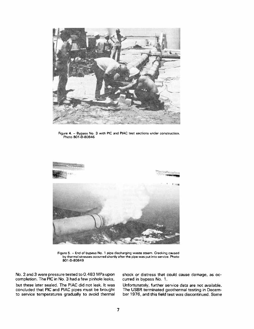
Figure 4. -Bypass No.3 with PIC and PIAC test sections under construction.Photo 801-0-80846
Figure 5. -End of bypass No.1 pipe discharging waste steam. Cracking causedby thermal stresses occurred shortly after the pipe was put into service. Photo801-D-80849
No.2 and 3 were pressure tested to 0.483 MPa uponcompletion. The PIC in No.3 had a few pinhole leaks,
but these later sealed. The PIAC did not leak. It wasconcluded that PIC and PIAC pipes must be broughtto service temperatures gradually to avoid thermal
shock or distress that could cause damage, as oc-curred in bypass No.1.
Unfortunately, further service data are not available.The USBR terminated geothermal testing in Decem-ber 1976, and this field test was discontinued. Some
7

further exposure was achieved when the facility was operated for a while by ERDA (Energy Research and Development Administration), but no observations were made nor data taken. The PIC pipes from by- pass No. 1 were returned to Denver in FY78, but nothing was done with them. Salt encrustations were evident in the cracking pattern so leakage must have occurred. The replacement pipes were given to BNL (Brookhaven National Laboratory) for testing under their geothermal program with DOE (Department of Energy).
Shadow Mountain Dam Field Tests, FY74-FY83
During the latter half of FY74, Division of Research personnel, LM (Lower Missouri) Region personnel, and Colorado-Big Thompson Project personnel en- gaged in discussions to develop a field test program in the spillway of Shadow Mountain Dam (see fron- tispiece). The concrete in the spillway was showing some degradation, and repairs were anticipated. The structure presented an ideal test site to evaluate the field performance of experimental repair materials.
In July of 1975, a multifaceted test program was developed, which included surface impregnation, a PC overlay, three epoxy overlays, and a series of coatings to be applied by the Applied Sciences Branch. The proposed experimental repair program was submitted to the LM Region in a letter dated August 4, 1975, and approval was given by a re- sponse dated August 11, 1975. The work was per- formed from August 13-22, 1975.
A 3.0- by 9.8-m area was sandblasted and treated by surface impregnation. The surface-impregnation treatment included drying at a surface temperature of 121 “C for 60 hours with a forced hot-air heating system, cooling for 60 hours, impregnation by grav- ity soaking for 9 hours with a 95-mass percent MMA and 5-mass percent TMPTMA monomer system, and thermal catalytic polmerization at 77 “C. The monomer application rate was approximately 7.3 kg/m*.
The PC overlay was placed on an area 2.1 by 6.1 m. About half of the area had been treated by surface impregnation. The PC was prepared by mixing a VE (vinyl ester) resin with a graded aggregate in the ratio of 8 parts aggregate to 1 part resin by mass. A VE resin bond coat was applied to the concrete surface just before the overlay application. The PC was mixed in a small mixer and applied by hand, using conven- tional concrete finishing trowels. The PC overlay av- eraged about 13 mm in thickness. The edges of the overlay were featheredged.
Epoxy mortar overlay No. 1 was a two-component, 100 percent solids, polyamide epoxy resin, which the
manufacturer claimed could be applied to damp con- crete at temperatures as low as 4 “C. The epoxy resin was mixed with a graded sand in a 1:6 epoxy-to- sand ratio. Epoxy mortar overlay No. 2 was prepared using another two-component, loo-percent solids, polyamide epoxy resin with manufacturer’s claims similar to the epoxy resin used in overlay No. 1, but supplied by a different manufacturer. The No. 2 mor- tar was prepared using a 1:6 epoxy-to-sand ratio. Epoxy mortar overlay No. 3 was prepared with a two- component, loo-percent solids, polysulfide epoxy resin meeting all requirements of Federal Specifica- tion MMM-B-350B for type II flexible epoxy resin ad- hesive binder. This resin was also mixed with a graded sand in a 1:6 epoxy resin-to-sand ratio. All of the epoxy overlays were applied by hand, as were the PC overlays.
A schematic layout of the experimental repairs on the floor of the spillway is shown on figure 6. Full details of the applications are documented in an in- terim report entitled “Experimental Repair of Shadow Mountain Dam Spillway” (appendix D). Included in this report are evaluations of performance after 1 month and after 9 months of service.
The enclosure used for drying and for polymerization of impregnated monomer in the surface impregnation process during the drying cycle is shown on figure 7. Application of the VE PC (vinyl ester polymer con- crete) overlay is shown on figure 8.
In addition to the l-month and g-month inspections and evaluations, the experimental repairs were in- spected after 13 months and 21 months of service and exposure.
Briefly, the results after 21 months were as follows:
a. The exposed surface-impregnated area ap- peared to be in good condition; further surface deterioration did not occur.
b. An area coated with only the VE resin showed no further deterioration from the slight erosion found after 1 year.
c. The VE PC appeared to be in good condition with some minor cracking and slight surface ero- sion evident.
d. The Federal specification type epoxy mortar, epoxy overlay No. 3, showed some random crack- ing, some softening that resulted in surface rip- pling, and some disbonding.
e. The two commercial epoxy mortar overlays showed surface deterioration, severe cracking, some softening in No. 2, and drumminess.
8

SURFACE IMPREGNATION
EPOXY OVERLAY APPLIED ON DAMP CONCRETE SURFACE
t I
EPOXY OVERLAY NO. 3
I Tl
EPOXY OVERLAY 1 NO.21 1 I 1 I I
EPOXY OVERLAY
+ P.C. OVERLAY
1 I
\
L -- i I I
COATINGS
I I
WATER FLOW
Figure 6. - Schematic layout for experimental repairs on the floor of the Shadow Mountain Dam spillway.
9
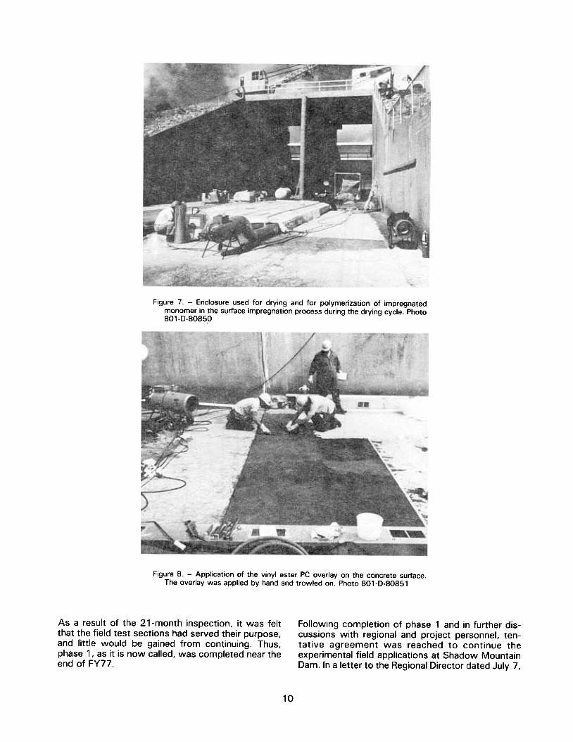
Figure 7. -Enclosure used for drying and for polymerization of impregnatedmonomer in the surface impregnation process during the drying cycle. Photo801-D-80850
Figure 8. -Application of the vinyl ester PC overlay on the concrete surface.The overlay was applied by hand and trowled on. Photo 801-D-80851
As a result of the 21-month inspection, it was feltthat the field test sections had served their purpose,and little would be gained from continuing. Thus,phase 1, as it is now called, was completed near theend of FY77.
Following completion of phase 1 and in further dis-cussions with regional and project personnel, ten-tative agreement was reached to continue theexperimental field applications at Shadow MountainDam. In a letter to the Regional Director dated July 7,
10

1977, continued field testing was proposed. Phase 2 would include removal of the test materials from phase 1, and placement of a machine-applied PC ov- erlay over most of the left side of the spillway. Phase 3 would be to surface impregnate the right half of the spillway floor by contract. Possible development of a polymer surface treatment for the spillway walls would be undertaken under the DR-256 program.
Laboratory preparations for the phase 2 program were completed under the DR-256 program, except for a trial application of the PC on a sidewalk at the DFC. Field preparations were made by project per- sonnel.
For phase 2, a Bidwell Model OF400 concrete paving machine was rented from the manufacturer. The USBR was committed to a field demonstration of a machine-applied overlay at one of its projects as part of its contribution to a cooperative program with FHWA for development of a VE PC overlay for bridge surfacing.
The phase 2 work at Shadow Mountain Dam was accomplished from July 18-22, 1977. During the re- moval of the four overlay test sections from phase 1, it was noted that in all cases the overlays were bonded better to the concrete treated by surface im- pregnation than to the sections overlayed on the non- treated concrete.
The machine-applied VE PC overlay was placed with the Bidwell concrete paver, which had been designed for placing a dense low-slump concrete (see fig. 9). The objective of this phase of the program was to demonstrate the feasibility of using a concrete paving machine to apply a PC overlay and to observe its performance under field exposure conditions. The concrete paver required no modifications to apply the PC overlay. The overlay was placed on an area of about 8 by 20 m, with a nominal thickness of 25 mm.
The VE PC was prepared by mixing 7.5 to 7.75 per- cent (by mass) VE resin with a dried graded concrete aggregate in 0.25-m3-capacity drum-type concrete mixers. The mix was moved from the mixers to the test area in wheelbarrows, ahead of the paving ma- chine. The machine spread and leveled the PC mix- ture and compacted and vibrated it in the finishing operations.
The day after placing, a system of fine cracks forming roughly circular patterns about 300 mm in diameter was observed in the PC overlay, (see fig. 10). In some areas, horizontal cracking occurred in the concrete just below the contact plane with the PC overlay, producing several delaminated areas. In other areas the PC overlay was intact and tightly bonded to the concrete. Both types of cracking were attributed to
the shrinkage of the polymer during polymerization.
The field test demonstrated the feasibility of using a concrete paving machine to apply the PC overlay, but also pointed out the need to control the shrinkage that occurs during the polymerization of the PC mix.
In 1978, the overlay was examined cursorily during the surface impregnation work and in more detail in September 1979. Further cracking had not devel- oped, but the inspections revealed progressive con- tinuation of delamination. Two areas of the overlay had been washed out. After these inspections ten- tative plans were made to remove the PC overlay and apply a new overlay when an improved PC was de- veloped. This was expected before the summer of 1981.
Phase 3 of the experimental work at Shadow Moun- tain Dam was scheduled for FY78. This phase was to demonstrate the surface impregnation process on a portion of the right side of the spillway floor; the work was to be performed by contract. The surface impregnation technique was developed by the USBR under a cooperative program with FHWA, which was interested in improving the durability of highway bridges. The USBR’s interest was in improving the durability of other pavements, particularly waterways on grade.
Contract Specifications 70-COO38 were issued on January 25, 1978 [13]. Contract No. 8-07-70- COO38 was awarded for $34,506 to Concrete Spe- cialties, Inc., of Fargo, North Dakota on April 21, 1978. On July 6, 1978, the notice to proceed was issued by the authorized representative of the Con- tracting Officer to start work on July 25, 1978-the date the operation of the spillway would be terminated for the 1978 season. Between award of the contract and notice to proceed, the contractor’s proposed procedures and specifications were re- viewed and modified or approved, and the work was started as soon as the spillway was available, on July 25.
The contractor’s plan was to divide the total area into five sections of equal length and to work on one or two sections at a time using two enclosures for the processing.
Cleaning was started with a small commercial metal- shot blaster, (see fig. 11). in lieu of sandblasting. However, this process was extremely slow and re- quired numerous passes to satisfactorily clean the surface. In addition, the contractor experienced fre- quent equipment breakdowns. Eventually, the origi- nal blaster was replaced with a new, larger machine that was more effective. The contractor’s principal reason for using the new machine was that it almost
11

Figure g. -Bidwell Model OF400 concrete paving machine finishing the VE PCoverlay during the first field trial. Photo 801-D-80852
Figure 10. -Pattern cracking the the VE PC overlay examined by research andfield personnel. Photo 801-0-80853
ture had to be held for 8 hours. One set of heaterswas used, alternating between the two enclosures.
The first enclosure is shown during the cooling cycleon figure 12. In this photograph the roof is partiallyremoved, and the infrared heaters are in place.
eliminated cleanup of sandblasting residue becauseit recycled the shot and vacuumed the dust. Onlyminor cleanup of residual shot was required.
The enclosures were prefabricated to span one-fifthof the total length to be treated. The sidewalls wereof frame and insulation construction, with steeltrusses to support the insulation roof. The heatersfor drying and polymerization were gas-fired infraredradiant tube heaters suspended about 1 m above thesurface. The system delivered approximately11.4 MJ per m2 of surface, raising the concrete tem-perature to 121 °C in about 4 hours. That tempera-
The cooling cycle was the most time-consuming partof the process. The specifications required coolinguntil the surface temperature reached 38 °C. Frequentlight showers complicated this matter, and the cool-ing took as long as 41 hours.
12

Figure 11. -Cleaning the concrete surface with commercial shot blast equipment.The result of the first pass is shown. As many as six passes were neededto get acceptable cleaning. Photo 801-D-80854
Figure 12. -The first enclosure, during the cooling cycle of the surface impreg-nation process. Photo 801-D-80855
August 25, 1978. In all, the job took about twice thetime originally estimated by the contractor, but sub-Stantially less than allowed by the contract.
The USBR's technical advisor was present on thejobsite from July 25 to August 8, 1978, to train thetwo project inspectors, to ensure compliance withspecifications, and to modify the requirements if nec-essary. Thereafter the technical advisor made spotvisits during the critical phases of the processing.Because this was the first contract for surface im-pregnation, numerous other persons interested in the
In an effort to maintain dryness, aluminum covers forthe insulation roof were fabricated, and during thenonheating cycles these were covered with polyeth-ylene. The aluminum covers on the second enclosureare shown on figure 13. The enclosures were partiallydisassembled during the cooling cycle to speed cool-ing.
The work proceeded through August 20, 1978,when the last of the five areas was completed. Allsections had bonded sand on the surface from thepolymerization cycles. Removal of this bonded sandand cleanup of the area were completed on
13

Figure 13. -The second enclosure, with aluminum covers on the roofing. Photo801-D-80856
process visited the jobsite throughout the period ofperformance. One significant trip was made by theDivision of Research Safety Engineer. He found thatpersonnel exposure did not exceed 24 p/m of MMA,well below the 100 p/m TLV (threshold limit volume).
Table 3. -Core tests of polymer penetrations into the spillwayfloor at Shadow Mountain Dam.
Area Location Polymer depthsmm
Comments
UpperMiddleLower
9.5-12.77.9- 9.59.5-12.7
2 Upper
Middle
15.9-19.012.7 dark band 1.6 mm
thick below
1.6-mm leached
surfaceLower 6.4- 9.5
3 UpperMiddle
Lower
7.9
9.5-12.7
4.8- 6.4 1.6-mm surface
leaching. light zoneto 22.2 m
Cores were taken from the five treated areas to checkon the effectiveness of the impregnations. Area No.5, the first area treated, was cored before the otherfour areas were impregnated. Polymer penetrationsranged from 12.7 to 15.9 mm. The results of thecoring from the other areas are presented in table 3.The cores were taken from the upper, middle, andlower sections of each area and were broken length-wise to show the polymer penetration. Area 5 wasthe first treated, area 2 the second, area 4 the third,area 1 the fourth, and area 3 the fifth, and last areatreated.
All cores showed unusually dark polymer penetra-tions, indicating high polymer concentrations in thetreated zones. The relatively shallow depths of pen-etration were expected, as previously experiencedwith slabs on grade. The specifications requirementfor a maximum 38 °C surface temperature at mon-omer application, rather than 38 °C at a depth of25 mm (the usual point of temperature measurementfor bridge decks), may have affected the penetrationand denseness of color in the treated zone.
4 UpperMiddle
Lower
6.4-12.79.5-12.76.4- 7.9
deterred. Annual inspections since have shown es-sentially no changes. Phase 3 at Shadow MountainDam is considered fully successful.
Plans for phase 4 were discussed early in FY79, butbecause of the reduced DR-381 budget for that year,no work at Shadow Mountain Dam was scheduled.The phase 4 program was developed in FY8O, butwas dependent on the development of an improvedVE PC in the DR-256 studies. Phase 4 would includeremoval of the PC overlay from the left side of the
The impregnated portion of the spillway was in-spected after exposure of 1 year and was found tobe sound and unchanged in appearance. No hollow-ness, delamination, or weak areas were detected.Surface raveling from freeze-thaw action had been
14

spillway, which was applied in FY77 and was show- ing substantial distress, followed by machine appli- cation of the improved VE PC overlay. At that time, the USBR had a Bidwell Model OF400 paving ma- chine with 3.7-m screeds, which was procured under a research-development program with FHWA and was to be used to apply the overlay.
During FYBO, three VE PC trial mixes were made us- ing different additives to reduce polymerization shrinkage. Although shrinkage was reduced, none of the mixes were satisfactory, as reported in the DR- 256 Annual Progress Report for FY80 [ 141. However, this did not seriously affect the phase 4 program because extensive runoff and spillway operations kept the spillway unavailable during FYBO. The work was rescheduled for FYBl when normal operations would make the spillway available from about late July to early October.
During FYBl under the DR-256 program, 33 addi- tional VE PC mixes were tested for reduced shrink- age, as reported in the FY81 Annual Progress Report [ 151. A low-shrinkage mix (PC 263), which contained 7-l/4 percent low-viscosity VE resin, fly ash, and a polymer powder, was selected for the application at Shadow Mountain Dam. However, when it was time to batch for the job, the fly ash and fine aggregate were not available in sufficient quantities. The mix was modified; F-95 Ottawa sand was substituted for fly ash. This modified mix (PC 285) had 0.15 percent shrinkage (compared with 0.14 percent for the orig- inal mix), about half the shrinkage of the PC applied in FY77. Mix design data are presented in table 4. Full details can be obtained from [15].
Arrangements were made in mid-l 98 1 with the Proj- ect Manager for the work to be undertaken during the fall. Before the arrival of a crew from the E&B Center, project personnel removed the old overlay
Table 4. - Mix PC 285 - 7-l/4 percent VE Mix with F-95 Ottawa sand, silica, and polymer powder.
Aggregated system
Size (mm) or materials Percent
Resin system (7-l/4 percent of total mass)
Material Percent
9.5 34.3 65 cps shell VE 97.2 2.36 15.5 CHP 1.5 1.18 12.0 CON 0.3 0.60 8.7 Silane 1.0 0.30 6.8 100.0 F95 Ottawa Sand 14.2 Silica flour 5.5 Pigment Polymer powder 3.0
100.0 Ti02 0.12 percent of aggregate mass
Carbon black 0.014 g/kg aggregate
with an airpowered jackhammer. Underlying deteri- orated concrete was removed with a scabbler and final cleaning was done by sandblasting. All equip- ment, materials, and supplies were delivered before September 1, 1981.
The actual application was made from September 1 to 16, 1981. The removal and cleaning operations produced a number of areas cut about 75-mm into the surface. These were repaired by filling with the VE PC and compacting and rough finishing with a gasoline engine-powered vibrating screed (see fig. 14). Approximately 35 percent of the surface was treated in this way. The patched areas were cured 4 to 5 days and lightly sandblasted just prior to the overlay application. The patches were sound, well bonded to the concrete substrate, and contained only a few small hairline cracks.
The VE PC overlay was applied in two passes with the Bidwell paver over a period of several days, (see fig. 15). Several problems were encountered includ- ing rain on the first day, difficulties in placing and finishing the PC, and premature polymerization of the bond coat and the PC. The overlay was sawcut after the material polymerized to form grooves on about l-m centers in an attempt to control cracking.
Because of the premature polymerization of the PC, a poorly finished and rough surface was produced. About a week after the machine application, a hand- troweled polymer mortar was applied to smooth the rough areas in the surface and at the ends of the overlay.
Approximately 2 weeks after completion of the ma- chine application, the overlay was closely inspected. The PC applied during the first pass, before the rain, was in the best condition. This area had been applied over a rubber modified VE primer coat and contained essentially no patched areas. The remainder of the first pass, applied over numerous patched areas, contained frequent cracks and drummy areas. The second pass, with the resin-rich PC mix, contained more cracks and drummy areas than the first. Be- cause these cracks were late in forming, it was thought that the coefficient of thermal expansion was the principal contributing factor. In only one instance did a crack follow a sawcut, otherwise they formed in a random pattern.
Cores were drilled through the PC overlay from areas that indicated disbonding or shearing by hammer tap- ping. The overlay was found firmly bonded to the concrete and indicated no failure or distress. The only horizontal cracks found in the cores were located 12 to 50 mm below the PC-concrete interface. Three of the five cores did not contain cracks. From such a small sampling, it was not possible to determine if
15

Figure 14. -Deep holes in the surface were filled with VE PC and finished witha vibrating screed prior to the overlay application. Photo SO1-D-SOS57
Figure 15. -The paving machine applying the VE PC overlay on the first pass.At this point all was going well. Photo 801-D-80858
the cracks existed prior to PC application or if the PCapplication caused the cracking. Previously, cracksof this nature had formed in the concrete immediatelybelow the PC-concrete interface.
hammer tapping, did not contain horizontal cracks as
expected.
This particular field test well illustrated the difficultiesin moving experimental materials from the laboratoryto the field. At this time, a satisfactory VE PC is notavailable for machine-applied overlays, and furtherdevelopmental work is not planned.
The mechanism for crack formation so deep in theconcrete has not been defined. It is also not under-stood why hollow-sounding areas, as determined by
16
Although the overlay is cracked and drummy, it haspresented no problems in the operation of the spill-way during 1982 or 1983. The most notable changeis that the cracking is more visible. The overlay waslast inspected on May 25, 1983. During that inspec-tion, plans were developed to remove a portion ofthe VE PC overlay and replace it with a commerciallyavailable acrylic PC that was being field tested atother sites. This would be phase 5 at Shadow Moun-tain Dm, the final work at that site scheduled underthe DR-381 program.
shotcretes under DR-326, Shotcrete for Tunnel Sup-
ports [ 16].
Polymer shotcretes had been developed, and a majorfield test planned for FY77. However, because com-parative data for polymer concretes had not beendeveloped, and information was not available in theliterature, a preliminary test program was scheduledunder DR-381 .Three or more specimens of 10 dif-ferent sizes and/or shapes were tested for com-pressive strength, and the data was documented byH. C. Riffle in a memorandum report [17]. The rela-tionships resulting from this preliminary study arepresented in table 5. Specimen sizes have been con-verted to metric for this table .
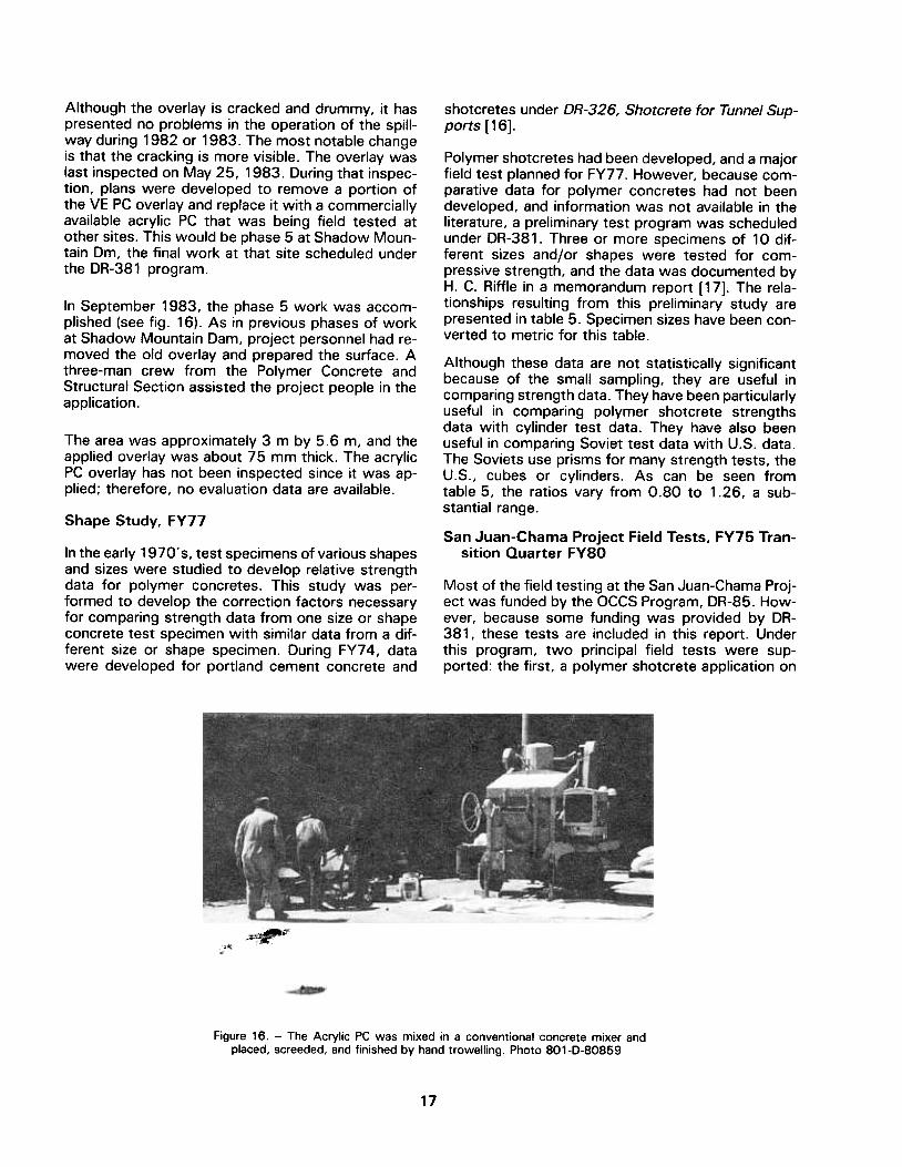
In September 1983. the phase 5 work was accom-plished (see fig. 16). As in previous phases of workat Shadow Mountain Dam, project personnel had re-moved the old overlay and prepared the surface. Athree-man crew from the Polymer Concrete andStructural Section assisted the project people in theapplication.
The area was approximately 3 m by 5.6 m, and theapplied overlay was about 75 mm thick. The acrylicPC overlay has not been inspected since it was ap-plied; therefore, no evaluation data are available.
Shape Study. FY77
Although these data are not statistically significantbecause of the small sampling, they are useful incomparing strength data. They have been particularlyuseful in comparing polymer shotcrete strengthsdata with cylinder test data. They have also beenuseful in comparing Soviet test data with U.S. data.The Soviets use prisms for many strength tests, theU.S., cubes or cylinders. As can be seen fromtable 5, the ratios vary from 0.80 to 1.26, a sub-stantial range .
San Juan-Chama Project Field Tests, FY75 Tran-sition Quarter FYSOIn the early 1970's, test specimens of various shapes
and sizes were studied to develop relative strengthdata for polymer concretes. This study was per-formed to develop the correction factors necessaryfor comparing strength data from one size or shapeconcrete test specimen with similar data from a dif-ferent size or shape specimen. During FY74, datawere developed for portland cement concrete and
Most of the field testing at the San Juan-Chama proj-ect was funded by the OCCS Program, DR-85. How-ever, because some funding was provided by DR-381 , these tests are included in this report. Underthis program, two principal field tests were sup-ported: the first, a polymer shotcrete application on
~
~
Figure 16. -The Acrylic PC was mixed in a conventional concrete mixer andplaced, screeded, and finished by hand trowelling. Photo 801-D-80859
17
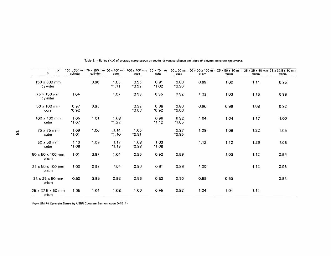
Table 5 - Ratios (V/x) of average compresslon strengths of various shapes and stzes of polymer concrete specimens
Y X 150x300mm75x150mm 50xlOOmm 100x100mm 75x75mm 5Ox50mm 50x50x100mm 25r50x50mm 25n25x50mm 25x37.5x50mm
cylinder cylinder
0.96
0.93
1 .Ol
1.06
1.09
0.97
0.97
0.86
1.01
core
1.03 ‘1.11
1.07
1.08 ‘1.22
.1.14 ‘1.10
1.17 ‘1.18
1.04
1.04
0.93
1.08
cube
0.95 ‘0.92
0.99
0.92 l O.83
1.05 l 0.91
1.08 ‘0.98
0.96
0.96
0.86
1.00
cube
0.91 l 1.02
0.95
0.88 l 0.92
0.96 ‘1.12
1.03 “1.08
0.92
0.91
0.82
0.95
cube
0.88 ‘0.96
0.92
0.86 ‘0.86
0.92 ‘1.05
0.97 l 0.95
0.89
0.89
0.80
0.93
prism
0.99
1.03
0.96
1.04
1.09
1.12
1.00
0.89
1.04
prism
1.00
1.03
0.96
1.04
1.09
1.12
1.00
0.90
1.04
prism
1.11
1.16
1.08
1.17
1.22
1.26
1.12
1.12
1.16
prism
0.95
0.99
0.92
1 .oo
1.05
1.08
0.96
0.96
0.86
150 x 300 mm cylinder
75 x 150 mm cylinder
50 x 100 mm core
100 x 100 mm cube
75 x 75 mm cube
50 x 50 mm cube
50x50x 100mm prism
25 x 50 x 100 mm prism
25 x 25 x 50 mm prism
25 x 37.5 x 50 mm
1.04
0.97 l 0.92
1.05 l 1.07
1.09 ‘1 .Ol
1.13 ‘1.08
1 .Ol
1.00
0.90
1.05 prism
‘From SM 74 Concrete Series by USER Concrete Secuon (code D- 15 11)
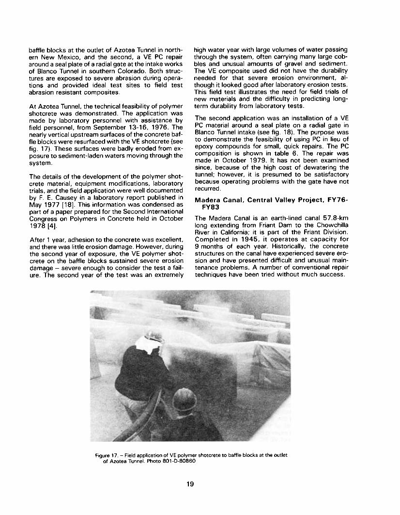
baffle blocks at the outlet of Azotea Tunnel in north-ern New Mexico, and the second, a VE PC repairaround a seal plate of a radial gate at the intake worksof Blanco Tunnel in southern Colorado. Both struc-tures are exposed to severe abrasion during opera-tions and provided ideal test sites to field testabrasion resistant composites.
At Azotea Tunnel. the technical feasibility of polymershotcrete was demonstrated. The application wasmade by laboratory personnel with assistance byfield personnel. from September 13-16. 1976. Thenearly vertical upstream surfaces of the concrete baf-fle blocks were resurfaced with the VE shotcrete (seefig. 17). These surfaces were badly eroded from ex-posure to sediment-Iaden waters moving through the
system.
The details of the development of the polymer shot-crete material, equipment modifications, laboratorytrials, and the field application were well documentedby F. E. Causey in a laboratory report published inMay 1977 [18]. This information was condensed aspart of a paper prepared for the Second InternationalCongress on Polymers in Concrete held in October1978 [4].
high water year with large volumes of water passingthrough the system, often carrying many large cob-bles and unusual amounts of gravel and sediment.The VE composite used did not have the durabilityneeded for that severe erosion environment, al-though it looked good after laboratory erosion tests.This field test illustrates the need for field trials ofnew materials and the difficulty in predicting long-term durability from laboratory tests.
The second application was an installation of a VEPC material around a seal plate on a radial gate inBlanco Tunnel intake (see fig. 18). The purpose wasto demonstrate the feasibility of using PC in lieu ofepoxy compounds for small, quick repairs. The PCcomposition is shown in table 6. The repair wasmade in October 1979. It has not been examinedsince, because of the high cost of dewatering thetunnel; however, it is presumed to be satisfactorybecause operating problems with the gate have notrecurred .
Madera Canal, Central Valley Project, FY76-FY83
The Madera Canal is an earth-Iined canal 57.8-kmlong extending from Friant Dam to the ChowchillaRiver in California; it is part of the Friant Division.Completed in 1945, it operates at capacity for9 months of each year. Historically, the concretestructures on the canal have experienced severe ero-sion and have presented difficult and unusual main-tenance problems. A number of conventional repairtechniques have been tried without much success.
After 1 year, adhesion to the concrete was excellent,and there was little erosion damage. However, duringthe second year of exposure, the VE polymer shot-crete on the baffle blocks sustained severe erosiondamage -severe enough to consider the test a fail-ure. The second year of the test was an extremely
Figure 17. -Field application of VE polymer shotcrete to baffle blocks at the outletof Azotea Tunnel. Photo BO1-D-BOB60
19
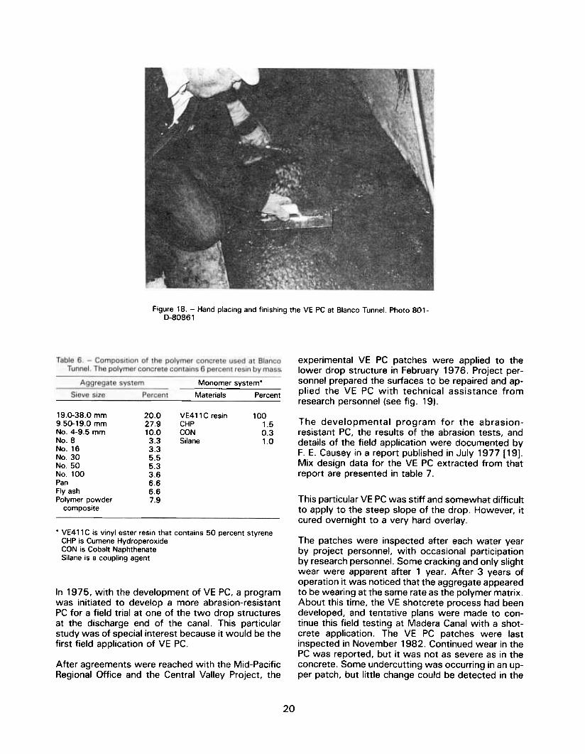
Figure 18. -Hand placing and finishing the YE PC at Blanco Tunnel. Photo 801-0-80861
experimental VE PC patches were applied to thelower drop structure in February 1976. Project per-sonnel prepared the surfaces to be repaired and ap-plied the VE PC with technical assistance fromresearch personnel (see fi9. 19).
Monomer system*
Materials Percent
20.027.910.03.33.35.55.33.66.66.67.9
VE411 C resinCHPCONSilane
100
1.5
0.3
1.0
The developmental program for the abrasion-resistant PC. the results of the abrasion tests. anddetails of the field application were documented byF. E. Causey in a report published in July 1977 [19].Mix design data for the VE PC extracted from thatreport are presented in table 7.
This particular VE PC was stiff and somewhat difficultto apply to the steep slope of the drop. However, itcured overnight to a very hard overlay.
19.0-38.0 mm9.50-19.0 mmNo. 4-9.5 mmNo.8No.16No.30No.50No.100PanFly ash
Polymer powdercomposite
.VE411 C is vinyl ester resin that contains 50 percent styreneCHP is Cumene HydroperoxideCON is Cobalt NaphthenateSilane is a coupling agent
The patches were inspected after each water yearby project personnel, with occasional participationby research personnel. Some cracking and only slightwear were apparent after 1 year. After 3 years ofoperation it was noticed that the aggregate appearedto be wearing at the same rate as the polymer matrix.About this time, the VE shotcrete process had beendeveloped, and tentative plans were made to con-tinue this field testing at Madera Canal with a shot-crete application. The VE PC patches were lastinspected in November 1982. Continued wear in thePC was reported, but it was not as severe as in theconcrete. Some undercutting was occurring in an up-per patch, but little change could be detected in the
In 1975, with the development of VE PC, a programwas initiated to develop a more abrasion-resistantPC for a field trial at one of the two drop structuresat the discharge end of the canal. This particularstudy was of special interest because it would be thefirst field application of VE PC.
After agreements were reached with the Mid-PacificRegional Office and the Central Valley Project, the
20

Figure 19. -The first field application of VE PC, made on the steep slope of adrop structure on the Madera Canal. Photo SO1-D-SOS62
Table 7. -Mix design data for experimental VE PC for Madera Canal drop structure.
Aggregate system
Aggregate size Percent Accumulated
retained, percent,-py mass b~s
Resin system(8 percent of total mass)
mm sieveMaterials Parts
O
25.7
18.6
14.2
8.8
6.2
3.5
11.5
11.5
025.744.358.567.373.577.088.5
100.0
100
1.5
0.750.5
Vinyl esterMethyl ethyl ketone
peroxideCobalt naphthenateSilane
9.54.752.361.180.60.30.15PanCement
3/8No.4No.8No.16No.30No.50No.100PanCement
satisfactory. Several modified mixes showed im-proved abrasion resistance in laboratory tests, andtrial applications at the DFC were scheduled. A low-viscosity resin was selected for the next outdoortrial. These tests were conducted on a vertical wallat the DFC. This particular low-viscosity resin did notmix well with the aggregate during the application.There was a high loss of fines causing a poor, non-uniform application (see fig. 20). The mixture alsohad a long polymerization time, which caused theapplied mixture to slough off the wall.
slope patch. Cracking that had been previously re-ported was seen, but additional cracking was notdetected. The VE PC patches were still hard and wellbonded. These patches have given some of the bestservice of any materials field tested under this pro-gram.In FY80, the application of a full floor of polymershotcrete in the second, or upper, drop structure onthe canal was planned. The technical feasibility of theapplication had been proven on the baffles at AzoteaTunnel, but the performance of the PC there was not
21

Figure 20. -Trial application of low-viscosity VE polymer shotcrete. The highloss of fines caused a poor, nonuniform application. Photo 801-0-80863
Several modifications were made to the mixture: thefines were reduced. the coarse aggregate was in-creased. and the catalyst was changed to shortenthe polymerization time. This resulted in a better ap-plication and quicker polymerization; however. it wasapparent that further developmental work wasneeded before the system would be operational. Thiswork was delayed because inclement weather sud-denly postponed outdoor trials. The outdoor trials atthe DFC could not be completed in time to accom-plish the field test at Madera Canal during FY80;therefore. the Madera field test was rescheduled forFY81.
In the interim, additional laboratory work was un-dertaken to improve the VE composite so that out-door trials could resume in the spring of 1980. As itturned out, none of the more abrasion-resistant PCmixtures could be applied satisfactorily with the shot-crete equipment. Further developmental work hasnot been undertaken, although the need still exists.
In 1979 and 1980, a number of commercial polymerconcretes were deve:oped and introduced into theconstruction market. Most of these products weretested by the USBR under the DR-256 program. Thetechnology for these products was based on earlywork with MMA polymer concretes by the USBR andothers. They generally are classed by the genericterms "acrylic" or "methacrylic" polymer concretes.
Most of these systems are quite fluid and easy tohandle, and some display performance comparableto the VE. With approval from the Central Valley Proj-ect, a field test of a particular commercial acrylic PCwas scheduled for FY81 .The commercial acrylic PCwas modified by the addition of fine aggregate sothat the mixture could be hand-applied to the steep34° slope without excessive slumping. This particularsystem could be applied by project personnel with-out shotcrete equipment.
A technique to apply the material was developed, inwhich the composite would be placed by hand insmall areas, in checkerboard fashion, starting at thebottom and working up. This technique was dem-onstrated at the DFC on a large test slab inclined atthe same slope as that of the actual structure.
The field application was accomplished from Decem-ber 15-19, 1980, by project personnel, with tech-nical assistance from an engineer from the Divisionof Research.
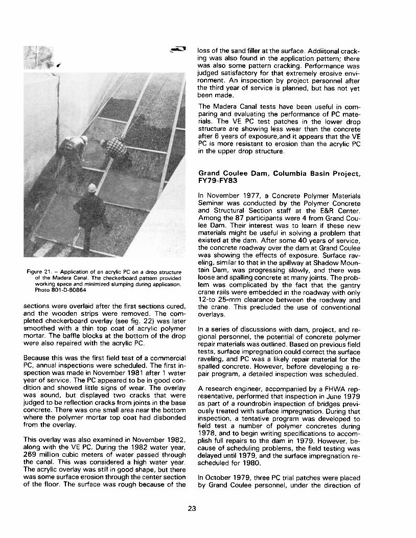
After the floor surfaces were cleaned by sandblast-ing, longitudinal and lateral wood strips were fas-tened to the concrete to block out the checkerboardpattern and to provide some support for the freshPC. The acrylic PC was troweled on alternate sec-tions of the surface by workmen supported by ropes(see fig. 21 ). The floor of the drop was overlaid withthe acrylic PC to a nominal depth of 50 mm. Alternate
22
~
,loss of the sand filler at the surface. Addiitonal crack-ing was also found in the application pattern; therewas also some pattern cracking. Performance wasjudged satisfactory for that extremely erosive envi-ronment. An inspection by project personnel afterthe third year of service is planned, but has not yetbeen made .
The Madera Canal tests have been useful in com-paring and evaluating the performance of PC mate-rials. The VE PC test patches in the lower dropstructure are showing less wear than the concreteafter 6 years of exposure,and it appears that the VEPC is more resistant to erosion than the acrylic PCin the upper drop structure.
Grand Coulee Dam, Columbia Basin Project,FY79-FY83
In November 1977, a Concrete Polymer MaterialsSeminar was conducted by the Polymer Concreteand Structural Section staff at the E&R Center.Among the 87 participants were 4 from Grand Cou-lee Dam. Their interest was to learn if these newmaterials might be useful in solving a problem thatexisted at the dam. After some 40 years of service,the concrete roadway over the dam at Grand Couleewas showing the effects of exposure. Surface rav-eling, similar to that in the spillway at Shadow Moun-tain Dam, was progressing slowly, and there wasloose and spalling concrete at many joints. The prob-lem was complicated by the fact that the gantrycrane rails were embedded in the roadway with only12-to 25-mm clearance between the roadway andthe crane. This precluded the use of conventionaloverlays.
Figure 21. -Application of an acrylic PC on a drop structureof the Madera Canal. The checkerboard pattern providedworking space and minimized slumping during application.Photo 801-D-80864
sections were overlaid after the first sections cured,and the wooden strips were removed. The com-pleted checkerboard overlay (see fig. 22) was latersmoothed with a thin top coat of acrylic polymermortar. The baffle blocks at the bottom of the dropwere also repaired with the acrylic PC.
In a series of discussions with dam, project, and re-gional personnel, the potential of concrete polymerrepair materials was outlined. Based on previous fieldtests, surface impregnation could correct the surfaceraveling, and PC was a likely repair material for thespalled concrete. However, before developing a re-pair program, a detailed inspection was scheduled.
Because this was the first field test of a commercialPC, annual inspections were scheduled. The first in-spection was made in November 1981 after 1 wateryear of service. The PC appeared to be in good con-dition and showed little signs of wear. The overlaywas sound, but displayed two cracks that werejudged to be reflection cracks from joints in the baseconcrete. There was one small area near the bottomwhere the polymer mortar top coat had disbondedfrom the overlay.
A research engineer, accompanied by a FHWA rep-resentative, performed that inspection in June 1979as part of a roundrobin inspection of bridges previ-ously treated with surface impregnation. During thatinspection, a tentative program was developed tofield test a number of polymer concretes during1978, and to begin writing specifications to accom-plish full repairs to the dam in 1979. However, be-cause of scheduling problems, the field testing wasdelayed until 1979, and the surface impregnation re-scheduled for 1980.
This overlay was also examined in November 1982,along with the VE PC. During the 1982 water year,269 million cubic meters of water passed throughthe canal. This was considered a high water year.The acrylic overlay was still in good shape, but therewas some surface erosion through the center sectionof the floor. The surface was rough because of the
In October 1979, three PC trial patches were placedby Grand Coulee personnel, under the direction of
23

"
Figure 22. -The fully resurfaced sloping floor of the Madera Canal drop structure.
before application of a smoothing top coat. Photo 801-D-80865
the responsible research engineer. The intent was toevaluate these PC materials under traffic until spec-ifications were needed, then to select the best ma-terial for the permanent repairs. During this tripdetailed plans were made to accomplish the per-manent repairs, and a tentative time schedule wasestablished. However, the schedule slipped to 1 982because of funding delays.
and presented at the 1983 Fall Convention of theAmerican Concrete Institute, Kansas City, Missouri,September 25-30, 1983 [21]. Further discussion isnot included in this report, except to say that at thiswriting, some distress is present in the PC repairs,and remedial measures are being considered.
A second program was undertaken at Grand CouleeDam in the fall of 1983. Three concrete roofs of therest room buildings of the new visitors' center facilityhad some surface faults. In addition, their appearancewas poor when viewed from other parts of the cen-ter. A thin polymer overlay had been developed in1980 for application at Spring Creek Debris Dam, andthis particular problem at Grand Coulee presented anideal site to further demonstrate the system.
Specific details of these field trials were documentedin a memorandum report by W. Glenn Smoak. datedJanuary 21 .1980. The application of one of the trialacrylic polymer concretes is shown on figure 23.
The details reported on site preparation, equipment,materials, and application techniques later served asa base for preparing the specifications. This consti-tuted the total effort in this particular program fundedby DR-381.
In September 1983. research personnel assistedproject personnel in the application of the thinpolymer overlay. Although service data are not avail-able yet. the tinted overlay produced an excellentuniform appearance. The mix design data from thereferenced travel report for the three-Iayer overlay arepresented in table 8.
The work did not end at this point, however. Withproject funding and technical assistance from thePolymer Concrete and Structural Section, specifica-tions for the repair of the roadway were preparedand issued as Solicitation No. 10-C0183 [20]. A con-tract was awarded by the project, under competitivebidding procedures, to Butler Sealants, Inc., of Se-attle, Washington. The repair program extendedfrom May to December 1982. The details of the re-pair program and the work accomplished were doc-umented by W. Glenn Smoak in a paper prepared for
The amounts listed in table 8 are sufficient to overlayapproximately 9.75 m2 with a total thickness of0.76 mm. The thin polymer overlay handles much likea 100-percent solids coating and can be applied byconventional coatings application techniques (seefig. 24).
24

dentate of the flip bucket. An area of approximately8.2 m2 was patched with an approximately 50-mmthickness of the PC. Because the flip bucket has notbeen dewatered since this repair, performance hasnot been evaluated .
The second demonstration was a repair of a gate sillat Dille Diversion Dam, Colorado-Big Thompson proj-ect, Colorado. In its sluiceway, flood conditions hadcaused abrasion of the concrete under and along theradial gate sill and wall plates. The damage, whichextended to depths as great as 150 mm, was deeperthan other damage repaired with PC. Three hundredpounds of commercial acrylic PC were used, withthree mixes developed for the different depths of re-pair. The more shallow areas of repair, those up-stream and those behind the base of the wallplates,were repaired with a mix extended with No.8 sand(2.36 mm). The sill plate and deeper downstreamrepairs, up to 150 mm, were made with a mix ex-tended with a blended aggregate sized from 2.36 to19.0 mm. The unaltered mix was used to bring therepair to grade and to featheredge to floor level. Therepairs only on the downstream side were inspectedin May 1983, and were found to be in good condition.There was no abrasion damage or disbonding tothese repairs although adjacent concrete showedcontinuing abrasion damage. Further repairs with thePC were planned by the project.
Figure 23. -Screeding one of the trial PC materials placed atGrand Coulee Dam. Photo 801-D-80866
Table 8. -Mix design data for the thin polymer overlay used atGrand Coulee Dam.
-
Intermediate and topping layersPrime layer
Vinyl ester resin 8.0 kgCumene 119 g
hydroperoxideCobalt naphthenate 23.8 g
The next demonstration was at Milburn DiversionDam, Middle Loup Division, Pick-Sloan Missouri BasinProgram, Nebraska. For about 15 years, its sluicewayhad experienced severe erosion damage in the chuteand on the baffle blocks and chute blocks. The irri-gation district planned conventional concrete repairsas a normal maintenance activity for the fall of 1981 .They also planned to field test two protective coat-ings and a PC overlay, all applied to the newly re-paired concrete. This provided an opportunity todemonstrate the PC overlay on relatively new con-crete.
40.8 93.8 9
Demonstrations at Various Projects, FY79-FY83
Beginning in late 1979, a series of field applicationswas made to demonstrate the performance of com-mercially available polymer concretes in actual re-pairs. The demonstrations provided realopportunities for small concrete repairs and affordedtraining opportunities for project personnel in the useof PC materials. In most cases, the DR-381 programfunded the procurement of the materials and assis-tance at the jobsite by technical experts from thelaboratory. The actual applications were generallymade by project or district personnel. Performanceof the materials were monitored by project and/orregional personnel. Further use of the materials wasleft at the option of these personnel.
In October 1981 .the selected commercial PC wasapplied by district personnel to the sloping portionof the sluiceway floor on the left chute. on one chuteblock. and on the face of one baffle block. The rightside of the sluiceway floor. which was the area ofgreatest wear. and the face of the baffle blocks hadbeen repaired first with concrete. These surfaces andthe original concrete on the left side of the floor andon the chute block were overlayed with the PC. Therepair nearing completion is shown on figure 25. Thecoatings work was done by Applied Sciences Branchpersonnel under another program .The first of these demonstrations was made at
Arthur R. Bowman Dam (formerly Prineville Dam),Crooked River Project, Oregon, in December 1979.A commercial acrylic PC was used to repair a dam-aged section of the spillway floor near the center
The repairs were examined about a week after ap-plication. The PC was tight. well bonded. hard. andfree of cracks. The overall appearance was excellent.
25
Vinyl ester resin 6.8 kgSilica flour 6.1 kgTiO2 (titanium dioxide) 0.7 kgCumene 204.2 g
hydroperoxideCobalt naphthenateCarbon black

.igure 24. -Roller application of the intermediate layer of the thin polymer overlayto the primed roof of a rest room building at Grand Coulee Dam. Photo 801-D-80867
Figure 25. -Placing an acrylic PC in the sluiceway at Milburn Diversion Dam.Photo 801-D-80867
A second inspection was made in June 1982 afterone season of sluicing. The PC overlay was found tobe sound, but abrading at a faster rate than expected.Maximum wear was measured at about 4.75 mm.Based on these results, several years of service werepredicted.
In February 1982, two repair systems were appliedto cavitation-damaged concrete in the outlet ofCarter Lake Dam, Colorado-Big Thompson Project,Colorado. One system was a commercial acrylic PC,the other was a commerciallow-modulus epoxy sys-tem' which the project was interested in testing.
26

Both systems were applied by project personnel withassistance by laboratory personnel: the PC on thefloor downstream of the right gate, and the epoxyon the floor and the wall downstream of the left gate .These repairs were inspected in May 1983 after 1year of operation. Both the PC and the epoxy werein good condition, and it was not possible to judgeif one had performed better than the other. Annualinspections are scheduled.
The patches were placed during two periods in June1983, by project personnel assisted by a three-mancrew from the laboratory. The acrylic PC and theepoxy-bonded concrete repairs were easily preparedand placed in the upper crack area. Some difficultieswere experienced with the mixing of the epoxy con-cretes because of their high viscosities and the lowambient temperature in the spillway. Their placementwas also difficult because of the steeper slope at thelower crack area (see fig. 26). Temporary forms wererequired to hold the epoxy concretes in place untilthey cured. These were plastic-covered plywoodsheets held in place by sandbags and buckets. As aresult. the surface finishes were somewhat poor .
In August 1980, responsibility for concrete repair re-search under PRESS Project DR-380 was transferredfrom the Concrete Section to the Polymer Concreteand Structural Section. Testing and evaluation ofepoxy compounds for the repair of concrete falls un-der this program. In June 1983, the South PlatteRiver Projects Office, Colorado-Big Thompson Proj-ect, Loveland, Colorado, requested assistance in re-pairing two transverse cracks in the spillway floor atGreen Mountain Dam, Colorado. The cracks, whichwere not at construction joints, had been repairedwith an epoxy material more than 10 years before .The repair material was disbonded and loose andcould have caused severe damage if removed duringa spill. High spillway flows expected to last for a longperiod of time were predicted for 1983. This pro-vided an opportunity to demonstrate and comparenew epoxy compounds with PC. Two commercialepoxy concretes and an acrylic PC were selected fora comparison with conventional epoxy-bonded con-crete. This was the final field demonstration sched-uled under the DR-381 program .
The repairs at Green Mountain Dam have not yet beenexamined. As expected, the 1983 spill was far9reater than normal; so the repairs were timely. Aninspection will be scheduled in the spring of 1984.A t that time the effects of the severe winter on thematerials will be evaluated.
Spring Creek Debris Dam, Trinity River Division,Central Valley Project, FYSO-FYS1
The work under DR-381 for Spring Creek DebrisDam, California, was unusual in that a special polymermaterial was developed to solve a unique problem.Specifications were issued by the Upper Missouri Re-gion to accomplish the program, but it is still uncom-pleted.
Spring Creek Debris Dam is on Spring Creek, a trib-utary of the Trinity River, in California. It is a smallembankment structure with an ungated chute spill-way and a concrete outlet works and stilling basin.The dam retains debris that would otherwise passto Spring Creek Powerplant. During the spring run-offs, low pH waters are produced from old mine tail-ings on the creek. and these produce extremelycorrosive environments in the channels, particularlyin the stilling basins, where these acidic waters re-main in pools for long periods of time.
In response to a regional request for a sealant, a thinpolymer overlay was developed using an adherent,chemically resistant VE resin, extended with inert fill-ers and pigments. Mix design data, sources of sup-ply, cost estimates, and specifications guideparagraphs were sent to the Regional Director by amemorandum dated May 12, 1980. The original mixdesign was similar to that shown in table 8, exceptthat about 10 percent more filler was used in theintermediate and topping layers.
Specifications No. 20-C0103(SF) were issued by theRegional Director on August 8, 1980 [22]. A contractwas awarded to Woolhethers Concrete company, alocal firm. Work began in Novmeber 1980, and tech-nical assistance was provided by an engineer from
Figure 26. -Application of epoxy concrete on the steep slopeof the spillway at Creek Mountain Dam. Photo 801-D-80868
27

shrinkage cracking, preparatory to phase 4 atShadow Mountain Dam. The application of one ofthe trial mixes is shown on figure 28. Grooves weretroweled over joints in the sidewalk in an attempt tocontrol the cracking that might occur. However,slight pattern cracking eventually occurred in all ofthese trials. The last two systems applied to the up-per sidewalk, the 8084+BA and Jhe 411 C-50 sys-tems, have not pattern cracked.
As mentioned previously, these overlay studies werepart of a joint study with FHWA to develop a ma-chine-applied VE PC for bridge decks and other pave-ments. Because the phase 4 overlay at ShadowMountain Dam was judged unsatisfactory, a VE PCmaterial was not available, and further mix designstudies were scheduled.
the laboratory. The contractor had considerable dif-ficulty in dewatering and cleaning the concrete. andsome delays were experienced. After a portion ofthe sloped section of the basin was cleaned. appli-cation of the prime layer began.(see fig. 27).
Before the priming could be completed and beforeany of the intermediate and topping layers could beapplied. seasonal rains stopped the work. At thiswriting. this work has not been rescheduled. Thus.the effectiveness of a thin polymer overlay in cor-rosive environments is still unknown. However.corrosion-resistance tests are being conducted in thelaboratory and at Grand Coulee Dam. but are not yetcomplete .
DFC Sidewalk Overlay Tests. FY77. FY79-FY82
Before each of the field trials of machine-applied PCoverlays. trial applications were made on portions ofparking lot sidewalks and concrete slabs at the DFCusing the Bidwell paver. Arrangements to use thesidewalks were made with the Buildings Manager.Public Buildings Service. General Services Adminis-tration. DFC.
In FY81 and FY82, these mix design studies wereundertaken under DR-256. Modifications that werestudied with two commercial VE resins included theuse of a commercial gap graded Clear Creek aggre-gate (laboratory standard aggregate), addition of asurfactant, and addition of fibrillar polypropylene fi-bers. Eight of these systems with various combina-tions of resin, aggregate, fibers, and surfactantswere hand applied to small sidewalk areas. Thesemixes were then adjusted for machine application,usually by increasing the total resin content. In thespring of 1982, these eight systems were machineapplied to a sidewalk at the DFC.
The first of these trials was made in 1977 beforephase 2 at Shadow Mountain Dam. Ironically, crack-ing did not appear in these trial overlays until afterthe first pass was applied at the dam. Ultimately, thecracking patterns in both of the overlays were similar .
Additionar trials were made in 1979, 1980, and1981, as new mixes were developed to reduce the
Figure 27. -Brush application of the prime layer of thin polymer overlay to thestilling basin at Spring Creek Debris Dam. Photo SOl-D-SOS69
28
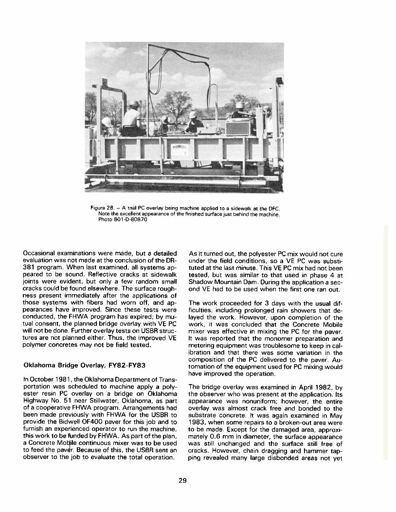
Figure 28. -A trial PC overlay being machine applied to a sidewalk at the DFC.Note the excellent appearance of the finished surface just behind the machine.Photo 801-D-80870
Occasional examinations were made, but a detailedevaluation was not made at the conclusion of the DR-381 program. When last examined, all systems ap-peared to be sound. Reflective cracks at sidewalkjoints were evident, but only a few random smallcracks could be found elsewhere. The surface rough-ness present immediately after the applications ofthose systems with fibers had worn off , and ap-pearances have improved. Since these tests wereconducted, the FHWA program has expired; by mu-tual consent, the planned bridge overlay with VE PCwill not be done. Further overlay tests on USBR struc-tures are not planned either. Thus, the improved VEpolymer concretes may not be field tested.
As it turned out, the polyester PC mix would not cureunder the field conditions, so a VE PC was substi-tuted at the last minute. This VE PC mix had not beentested, but was similar to that used in phase 4 atShadow Mountain Dam. During the application a sec-ond VE had to be used when the first one ran out.
The work proceeded for 3 days with the usual dif-ficulties. including prolonged rain showers that de-layed the work. However, upon completion of thework, it was concluded that the Concrete Mobilemixer was effective in mixing the PC for the paver.It was reported that the monomer preparation andmetering equipment was troublesome to keep in cal-ibration and that there was some variation in thecomposition of the PC delivered to the paver. Au-tomation of the equipment used for PC mixing wouldhave improved the operation.
Oklahoma Bridge Overlay, FY82-FY83
In October 1981. the Oklahoma Department of Trans-portation was scheduled to machine apply a poly-ester resin PC overlay on' a bridge on OklahomaHighway No.51 near Stillwater. Oklahoma. as partof a cooperative FHWA program. Arrangements hadbeen made previously with FHWA for the USBR toprovide the Bidwell OF400 paver for this job and tofurnish an experienced operator to run the machine.this work to be ~unded by FHWA. As part of the plan.a Concrete Mo ile continuous mixer was to be usedto feed the pav r. Because of this. the USBR sent anobserver to the job to evaluate the total operation.
The bridge overlay was examined in April 1982, bythe observer who was present at the application. Itsappearance was nonuniform; however, the entireoverlay was almost crack free and bonded to thesubstrate concrete. It was again examined in May1983, when some repairs to a broken-out area wereto be made. Except for the damaged area, approxi-mately 0.6 mm in diameter, the surface appearancewas still unchanged and the surface still free ofcracks. However, chain dragging and hammer tap-ping revealed many large disbonded areas not yet
29

broken out. As these were being removed additional disbonding occurred. The PC overlay was not tightly bonded and was easily removed with jackhammers and chipping hammers. The overlay broke cleanly from the surface. Some moisture was evident along the interface. This field trial was judged a total failure. Because this was a new bridge and the PC broke away cleanly from the deck, no further repairs were planned by the Oklahoma Department of Transpor- tation.
Roundrobin Inspection of Bridges, FYB3
During the performance of Project DR-381, the Polymer Concrete and Structural Section worked on several cooperative programs with other Govern- ment agencies. These were studies closely related to the DR-381 work, particularly those in cooperation with FHWA. From 1971-1974, laboratory studies were funded by FHWA, Office of Research, Materials Division, McLean, Virginia, for the USBR to develop the surface impregnation and polymerization proc- esses for concrete bridge decks (Contract No. 2-1- 12 14, dated December 7, 197 1). With development of the process, a second study was undertaken to implement the impregnation process by treating ac- tual highway bridges (Contract No. 6-3-0001, dated July 8, 1975): This contract extended to September 30, 1982, and all work was completed in May 1983, when the draft of the final report by W. Glenn Smoak was submitted to FHWA [23]. Throughout the implementation program, numerous bridges throughout the United States were treated through contracts with FHWA, with technical assis- tance by USBR research personnel.
In September 1983, three of these bridges were in- spected under the DR-381 program. This roundrobin inspection was scheduled in conjunction with the ap- plication of the thin polymer overlay at Grand Coulee Dam.
The first bridge was a small structure on State High- way No. 200 near Sand Point, Idaho, which had been impregnated in 1975. Its appearance had changed little; the typical pattern cracking was still visible and small quantities of polymer-bonded sand were still evident on the surface. Wheel wear paths were somewhat visible in the polymer-depleted zone at the surfce. Performance was judged to be satisfactory.
The second bridge was a precast, prestressed bulb- tee structure over the Santa Rosa Canal at Yakima, Washington, which was constructed in 1977. The roadway surfaces of its seven precast members were polymer impregnated at the precasting yard in Clackamas, Oregon, before shipment to the con- struction site. The bridge was found to be in excellent condition, almost unchanged since impregnation. No
cracks were found in the riding surface or from the underside. Freedom from cracks is the usual result in polymer-impregnated precast structures.
The third bridge was a two-lane concrete structure over Rattlesnake Creek on State Highway No. 36 near Redding, California. It was a newly constructed bridge when impregnated in late 1975. Unfortu- nately, a Caltrans contractor erringly installed a chip seal coat to the highway and bridge shortly before the inspection was made. The inspection was to be made before the seal coat was applied. Although the deck surface could not be examined, Caltrans per- sonnel reported that it was in excellent condition.
To fully evaluate the surface impregnation of the bridge decks, plans are being formulated to inspect and examine the other bridges treated under the im- pregnation program.
BIBLIOGRAPHY
[l] Selander, C. E., Development of Concrere Poly- mer Materials by the Bureau of Reclamation - A Summary Report, Bureau of Reclamation Report No. GR-1-75, Denver, Colo., June 1975.
[2] Program Review, WRPER (Water Resources Planning and Engineering Research), FY74 Ac- complishment, FY75 Program, Bureau of Recla- mation, Division of General Research, Denver, Colo. Research Project Statement, Project No. DR-381, p. 138, December 1974.
[3] Program Review, PRESS (Program Related En- gineering and Scientific Studies), FY82 Accom- plishments, FY83 Program, Bureau of Reclamation, Engineering and Research Center, Division of Research, Denver, Colo., Summary Project Statement, Project No. DR-381, pp. 97- 98, February 1983.
[4] De Puy, G. W., and Selander, C. E., “POLYMER CONCRETE - Trials and Tribulations,” Proceed- ings of the Second International Congress on Polymers in Concrete, College of Engineering, The University of Texas at Austin, Austin, Tex., pp. 461-482, October 25-27, 1978.
[5] Program Review, WRPER, FY75 Accomplish- menrs, FY76 Program, Bureau of Reclamation, Division of General Research, Denver, Colo., Re- search Project Statement, Project No. DR-381, p. 146, December 1975.
[6] Program Review, WRPER, FY76 Accomplish- ments, FY77 Program, Bureau of Reclamation,
30

Division of General Research, Denver, Colo., Re- search Project Statement, Project No. DR-381, p. 142, December 1976.
[ 71 Program Review, WRPER, FY77 Accomplish- ments, FY78 Program, Bureau of Reclamation, Division of General Research, Denver, Colo., Re- search Project Statement, Project No. DR-381, p. 138, March 1978.
[8] Program Review, WRPER, FY 78 Accomplish- men&, FY79 Program, Bureau of Reclamation, Division of Research, Denver, Colo., Research Project Statement, Project No. DR-381, p. 126, December 1979.
[9] Program Review, WRPER, FY79 Accomplish- menrs, FY80 Program, Water and Power Re- sources Service, Division of Research, Denver, Colo., Research Project Statement, Project No. DR-381, p. 130, February 1980.
[lo] Program Review, WRPER, FY80 Accomplish- ments, FY87 Program, Bureau of Reclamation, Division of Research, Denver, Colo., Research Project Statement, Project No. DR-381, p. 75, August 1981.
[ 111 Program Review, WRPER, FY8 7 Accomplish- menrs, FY82 Program, Bureau of Reclamation, Division of Research, Denver, Colorado; Re- search Project Statement, Project No. DR-381, page 67.
[ 121 Specifications No. 3OOC-392, Installing Polymer-Impregnated Pipe, East Mesa Test Site.
[ 131 Specificatiions No. 70-CO038, Surfce Impreg- nation of Spillway Floor, Shadow Mountain Dam, Colorado-Big Thompson Project.
[14] Causey, Fred E., Memorandum to Chief, Con- crete and Structural Branch; Subject: Concrete Polymer Materials Systems Research, DR-256 - Annual Progress Report FY80, October 31, 1980:
[ 151 Causey, Fred E., Principal Investigator Memo- randum to Chief, Concrete and Structural Branch; Subject: Engineering Materials Systems Re- search, DR-256 - Annual Progress Report FY81, October 28, 1981.
[16] Rutenbeck, Todd, unpublished data on GS-75 and SM-74 series strength tests, FY74.
[17] Riffle, H. C., Memorandum to Files; Subject: Study of Relationships of Size and Shape of Specimen to PC (Polymer Concrete) Strength (Part of DR-381 Polymer Applications Studies), January 28, 1977.
[ 181 Causey, F. E., Laborafory Investigation and Ex- perimental Field Application of Vinyl Esrer Poly- mer Shorcrere; Bureau of Reclamation, Report No. GR-6-77, Denver, Colo., May 1977.
[ 191 Causey, F. E., Vinyl Ester Polymer Concrere and Experimental Repair of Madera Canal Drop Srruc- rue, Bureau of Reclamation Report No. GR-7-77, Denver, Colo., July 1977.
[20] Solicitation No. lo-C0183, Polymer Impregna- tion of Roadway Surfaces, Grand Coulee Dam, Grand Coulee Project Office, Columbia Basin Project, Wash., 1982.
[21] Smoak, W. Glenn, “Polymer Impregnation and Polymer Concrete Repairs at Grand Coulee Dam,” a paper presented at the 1983 Fall Con- vention, American Concrete Institute, Kansas City, MO., September 25-30, 1983.
[22] Specifications No. 20-CO103(SF), Stilling Basin Rehabilitation, Spring Creek Debris Dam, Central Valley Project, Calif. August 8, 1980.
[23] Smoak, W. G., lmplemenrarion of Polymer Im- pregnation as a Bridge Deck Sealant, Bureau of Reclamation Report No. REC-ERC-84-11, Den- ver, Colo., 1984.
31


APPENDIX A
POLYMER IMPREGNATION OF CONSTANT HEAD ORIFICE TURNOUTS FOR GRAND COULEE DAM,
COLUMBIA BASIN PROJECT


UNITED STATES GOVERNMENT
Memorandum Memorandum Denver, Colorado
To : Head, Polymer Concrete and Structural Section DATE: June 12, 1975
FROM : Fred E. Causey, Chemical Engineer
SvBJe<rr: Polymer Impregnation of Constant Head Orifice Turnouts for Grand Coulee, Columbia Basin Project
Introduction
Two precast reinforced concrete constant head orifice turnout structures were designed for the Columbia Basin, Grand Coulee Irrigation System. Figures 1 through 8 show the design and assembled turnout. The structures were cast in the laboratory and impregnated in the Bureau’s facility. ‘IMo monomer systems were used to impregnate these two turnouts. These monomer systems were 60-40 styrene-TMP’IMA (trimethylol- propane trimethacrylate) and IMA (methyl methacrylate). The monomer systems were selected on the basis of availability of sufficient quantities for impregnation.
Impregnation
Two canal turnout structures consisting of 11 sections each and six 6-inch by 12-inch cylinders were impregnated with 60-40 styrene-l’?WlMA and MMA in five treatments. The large sections were loaded into the large drying oven with a 4,000-pound capacity forklift. The smaller sections were dried in the P-foot by P-foot by 6-foot capacity oven. All sections and 6x12’s were dried at 350° F and cooled to room temperature. The temperature was raised slowly as not to exceed 40’ F per hour in the heat cycle and thus oven control was so regulated that it took 8 hours to reach 350’ F. Specimens were cooled overnight.
The turnout sections are shown in table 1. After the specimens were weighed they were taken out to the impregnator on the forklift where they were loaded into the carrier with a crane. The one-piece stilling basin was impregnated in the vertical impregnator while the other sections were impregnated in the horizontal impregnator.
The vacuum pump was switched on and 23 inches of Hg (Denver mean 24.7 inches) were drawn. While the vacuum cycle was in progress, previous weighed drums of styrene and TMP’IMA for turnout NO. 1 and MM for turnout No. 2 catalyzed with one-half percent DA-79 (a-t-butylazo isobutyronitrile) were mixed by bubbling air through the monoier system. The weight mix ratio for thg styrene-T&fMA system was 60 percent styrene and 40 percent TMPTMA.
35
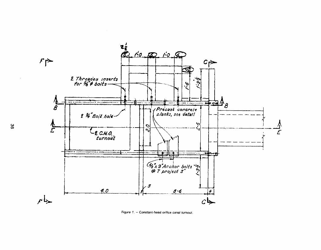
4 t A I
w&J t
36
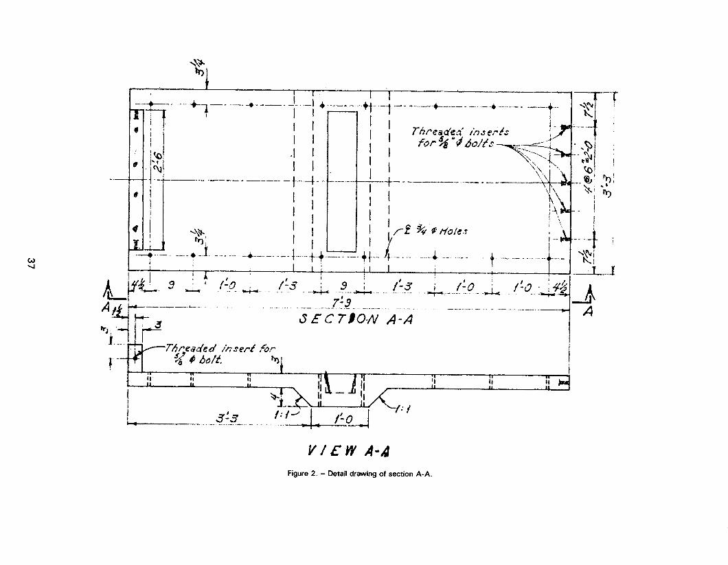
3
i I-+ + 1
--:
-r
37

g-8 uo!i3as $0 fiu!Me~p f!eiaa - ‘E amtj!j
sr-6r M3/A ___. -_ _. _ __ .._. ._ -.._ ._ . .._._ ,. _. _ ._. _ __-._. . . ._.. -._
---
i

+.,-v-s- _-_______... _ ___.__._._.-____._ -w&6 __... _- .- _.__ -_.I-- ______ -- _____._ I I ,-.--cG!-. P- L%
Figure 4. - Detail drawing of section C-C.
39

,
Figure 5. - Detail drawings of section D-D, and for bolt inserts and holes.
40

I--- *.I :;. -
, :- :’ . . t- ,.
-Y --’ -.
!
I
0 ,I w
. t ir-- --_.- .:: ..* 1 -5
41
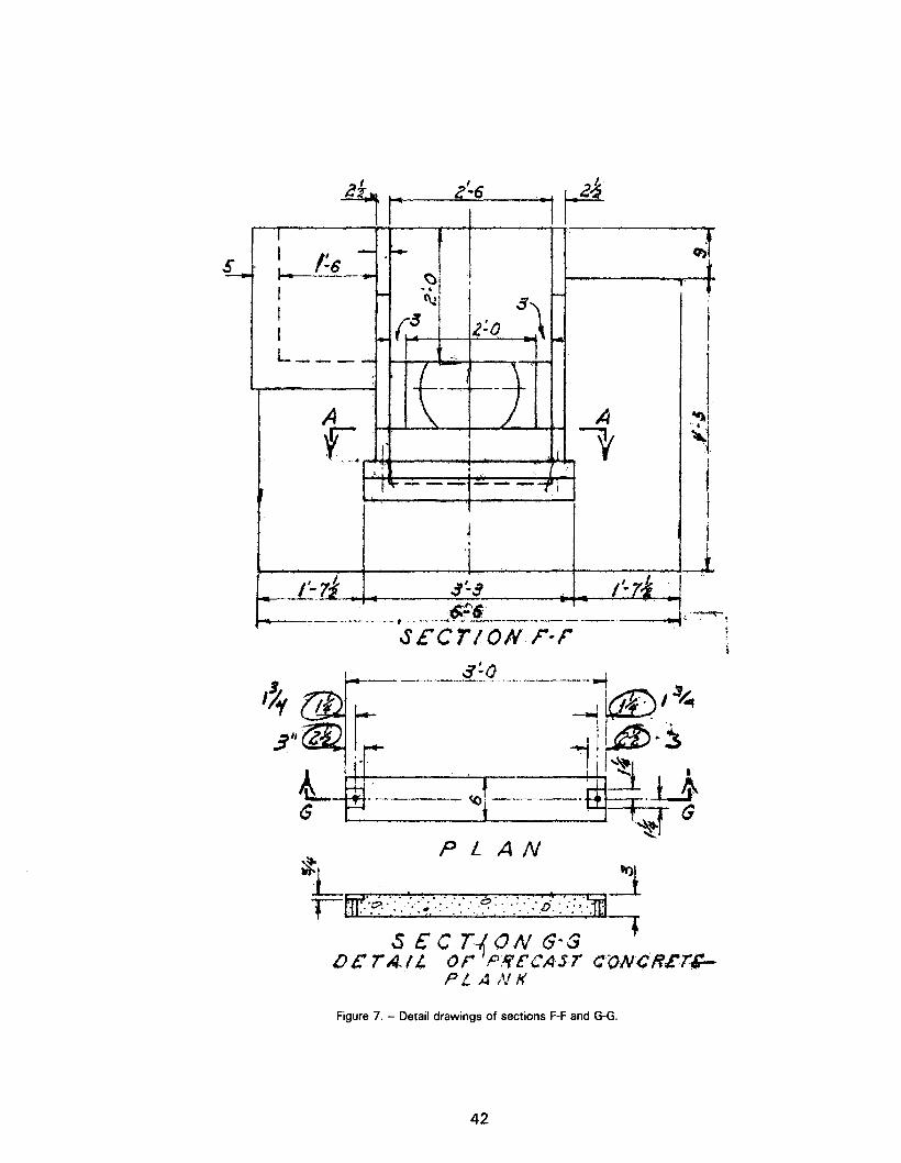
-
- ______ --.- _.._._ t __.- _---.-?-- - - --.- .-
SEC ?-/x3&V F-i-
t ~-~~~~~.~~.~~.‘~‘-‘~‘~~,~:~~.:~~.~~~-;:~~~
t
:.. *. . .T’.‘..‘._ . .,.‘. . . . . . I-
Figure 7. - Detail drawings of sections F-F and G-G.
42

Figure 8. -The assembled constant-head orifice canal turnout.
43

After the vacuum cycle was completed, the catalyzed monomer was drawn into the impregnator from the transfer tank by the 23 inches of vacuum. When the proper monomer level was reached, the valve to the impregnator was closed and monomer left in the line was transferred back into the transfer tank with compressed air. After the monomer transfer was completed, the vent valve was open to release the remaining vacuum. The impregnator was $hen slowly pressurized with compressed air to a pressure of 40 lb/i9 for horizontal impregnator with styrene-TklPTMA system and 50 lb/in with tqe MMA system. The vertical impregnator was pressurized to 40 lb/in for Bach impregnation. When pressure soak cycle was completed, the monomer was transferred back into the transfer tank.
Compressed air was blown through the impregnator and line to remove excess monomer before polymerization.
The monomer in the impregnated sections of the turnout was polymerized under water. Warm water was transferred from a large water heater into the impregnator-polymerization vessel using compressed air. Tempera- ture of the water brought in for each polymerization is given in table 1. The water around the turnout sections impregnated with 60-40 styrene-TMPTMA was raised to about 185’ F. Steam was used to heat this water and was shut off after this temperature was reached. The polymerization goes to completion in a couple hours. Turnout sec- tions impregnated with k&lA were done in similar manner with water temperature brought to 160° F. The water was drained the next morning, and compressed air was blown through to cool the specimens and to remove the last of the water. The turnout sections removed and weighed. Polymer loadings were calculated from the dried and impregnated weights. These data are shown in table 1.
Results
Polymer loading for the canal turnout sections ranged from 6 to 7 per- cent as was expected. The loading with styrene system was higher than the MMA system with styrene around 7 percent and MIA around 6 percent. Two 6x12’s impregnated with the styrene system were broken in compres- sion using celotex rathe than grinding. The average compressive strength was 8,325 lb/in . Similar impregnated 6x12’s with the styren? system and specimens which were ground gave an average of 17,590 lb/in Two 6x12’s impregnated with MMA were also tested using selotex and yielded an average compressive strength of 15,500 lb/in . The gsound specimens showed an average compressive strength of 19,800 lb/in . Complete compressive strength data are shown in table 2.
44

Table 1
WEIGHTS AND IMPREGNATION CYCLES
Test 1
Nine assorted pieces of a canal turnout section and two 6x12’s were dried 24 hours at 350’ F and cooled overnight, 8 hours were used to reach 350° F.
Impregnated with 60-40 styrene-TMPTMA L/ and one-half percent DA-79,&/ monomer temperature was about 40° F.
Cycle: 2 hours vacuum at 23 in Hg 3 hour pressure at 40 lb/in2
Polymerized under water overnight at 185’ F and 0 lb/in2
Spec. No. 31 6 x 12’s-
1 11.59 kg 12.45 kg 2 11.51 12.41
Turnout Large piece
Dry wt Imp wt
470.37 500.76 30.39 0.46
19.54 20.95 1.41 7.22 23.16 24.80 1.64 7.08 23.04 27.70 1.66 7.20
160.01 173.30 10.29 6.43 160.09 171.75 11.66 7.28
wt Poly
.86 kg
.90
% loading
7.42 7.82
Test 2
One stilling basin for turnout section was dried at 350’ F for 24 hours and cooled overnight, 8 hours was used to reach 350’ F.
Impregnated with 60-40 styrene-TMPTMA and one-half percent DA-79, monomer temperature was about 39’ F
Cycle : 2 hours vacuum at 23 in Hg 3 hours pressure at 40 lb/in2
Polymerized under water overnight at 175’ F.
45
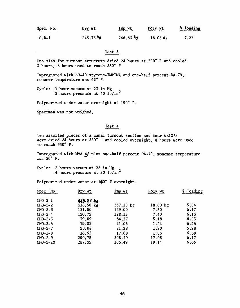
Spec. No. wt Dry
S.B-1 248.7&l
wt Imp Poly wt %
266.83 kg 18.08k9 7.27
Test 3
One slab for turnout structure dried 24 hours at 350° F and cooled 3'hours, 8 hours used to reach 350" F.
Impregnated with 60-40 styrene-'IMPTMA and one-half percent DA-79, monomer temperature was 45' F.
Cycle: 1 hour vacuum at 23 in Hg 2 hours pressure at 40 lb/in2
Polymerized under water overnight at 190" F.
Specimen was not weighed.
Test 4
Ten assorted pieces of a canal turnout section and four 6x12's were dried 24 hours at 350° F and cooled overnight, 8 hours were used to reach 350° F.
Impregnated with MMA 4/ plus one-half percent DA-79, monomer temperature Has 50° F.
Cycle: 2 hours vacuum at 23 in Hg 4 hours pressure at 50 lb/in2
Polymerized under water at 180" F overnight.
Spec. No. Dry wt Imp wt Poly wt % loading
CHO-2-1 CHO-2-2 CHO-2-3 CHO-2-4 CHO-2-5 CHO-2-6 CHO-2-7 CHO-2-8 CHO-2-9 CHO-2-10
mo* !$ 121:SO 120.75
79.09 19.82 20.08 16.62
290.75 287.35
337.10 kg 18.60 kg 5.84 129.00 7.50 6.17 128.15 7.40 6.13
84.27 5.18 6.55 21.06 1.24 6.26 21.28 1.20 5.98 17.68 1.06 6.38
308.70 17.95 6.17 306.49 19.14 6.66
46
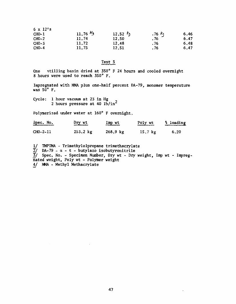
6 x 12's CHO-1 11.76 4 12.52 k'~ .76
11.74 12.50 ,76 3 6.46
CHO-2 6.47 CHO-3 11.72 12.48 .76 6.48 CHO-4 11.75 12.51 .76 6.47
Test 5
One stilling basin dried at 350' F 24 hours and cooled overnight 8 hours were used to reach 350' F.
Impregnated with MMA plus one-half percent DA-79, monomer temperature was 50' F.
Cycle: 1 hour vacuum at 23 in Hg 2 hours pressure at 40 lb/in2
Polymerized under water at 160' F overnight.
Spec. No. wt Dry wt Imp wt Poly % loading
CHO-Z-11 253.2 kg 268.9 kg 15.7 kg 6.20
l/ lMPl?4A - Trimethylolpropane trimethacrylate T/ DA-79-c-t - butylazo isobutyronitrile z/ Spec. No. - Specimen Number, Dry wt - Dry weight, Imp wt - Impreg- nated weight, Poly wt - Polymer weight &/ FJwA - Methyl Methacrylate
47

Table 2
COMPRESSIVE STRENGTHS
60-40 Styrene-TMPTMA System
Spec. No. Strength (lb/in2)
ST-1 8,280 ST-2 8,320
MMA System
Ground Spec. No.
CHO-1 CHO-2 s-4
Strength (lb/in2)
20,340 19,210 19,810
Un-n ground Celotex Spec. No. Strength (lb/in2)
CHO-3 15,280 CHO-4 16,770 s-2 15,350 s-3 14,820
4%

APPENDIX B
PROGRESS REPORT FOR FY75-76, POLYMER APPLICATIONS, DR-381


INFORMATIONAL ROUTING
~~~~c!rete and Struatural Branah@+
Head, Polymer Concrete and Struatural Sectioii
I t A%-- -,-Lb----- )---- ----- -- l _-------- Denver, Co&ado
June lBL8’L6- ---_ I I ----------- I r ---e-e -mm
H. C. Rfffle
I Progress Report for Fy75-76, Polymer Applioatlons, DR 381
_---------- I I
This progmm w~8 started in 1974 (FY75) to develop and dsmonstrk%<---------- the u8e of polymer aomposltes in field applioatlons. To date, khree applloationrr have been rmgde as follow8:
1. Irmtallatlon of polymer-impregnated ooncrete (PIG) 8nd a8be8to848ment (PIAC) pipe and polymer oonorete (PC) ditoh lining at the Geothermal Test Faolllty, East Ue88 Test Site, near Holtville, California
2. Installation of a prefabricated polymer-impegnated ooncrete turnout - W344E lateral - Wahluke Branoh Canal Laterals, Blook 253 - Speoifio8tions PrOjeot, Washington
3. Shadow Mountain Dam Spillway
The status of eaoh of the foregoing hereinafter.
No. DC-7068 - Columbia Ba8ln
repair8 - Grand Lake, Colorado
appliOatiOn8 i8 desorfbed separately
Installation of Pipe and Ditch Lining at the Geotherml Test F8aillty, Holtville, California
The Geothemal Test FaUility was 8eleated a8 a test site for polymer oompo8ite8 beoause there they oould be expolred to steam or brine8 of varloua oonoentrations from 0 to 100 000 part8 per mlllfon tot81 dissolved solids at temperature8 of 60' to 160% (140' to 3200P). Exposure Oonditions and location8 for the pipe and ditah lining iasterials are shown In table 1.
Three varieties of oomposlte materials will be installed at the Geothermal Test PaOility, a8 fOllOW8:
1. Polymer-Impregnated oonarete (PIG) pipe 2. Polymer-Impregnated a8be8to8-cement (PIAC) pipe 3. Polymer-conorete (PC) dltoh lining slab8
51

Coumaercially manufactured Class 12A50 concrete pfpe was purchased because this is the smallest (0.3048.metre = 12-inch) inside diameter reinforced oonorete pressure pipe available with the required rubber gasket joint (type R-4). These pipe sectiona were the shortest avail- able standard laying length of 6 feet 80 that they would Pit inside the existing Impregnation tank. The 0.2.mstre (80inch) 1.d. asbsstos- oement pipe Is a commercially produced Class AC45 with a 0.9%metro (3-ft j-in.) laying length. The pipe sections ware impregnated with 60-40 styrene-TMPTMA (trimethylolpropane trimethaorylate) monomer ryrtea and thermal catalytically polymerized at building 77 of the E&R Center. The PC ditch lining slabs are 0.565 by 1.181 metres (22-114 by 46-l/2 inches) with 63.5-millimetre (20l/2-Inch) thickness. These slabs are reinforced with 0.150 by 0.15-metre (60 by 6-inch) No. 10 gage steel welded wire fabric. The slabs contain 19.05~mm (3/4=lnch) maximum-size a&gregate and 8 percent 60-90 styrene-TMPTMA monomer by weight. This monomer was used because of its stability at higher temperatures.
The ob.jective of this application is to Investigate the capability and advantagea, If any, of these materials as compared to conventional materials such aa steel pipe. It Is now planned to determine their servloeability by periodic inspection and teats aftv about 2 and 5 years’ exposure to the aforementioned conditions. Concrete and asbestos-cement pipe were tested before impregnation for 3-edge bearing strength and water absorption in accordance with ASTH Designations: c 497 and c 500. These teats were also conducted on the impregnated and polymerized pipe. Results of these tests are shown in tables 2A, 2B, and 3. These teats are scheduled for sections of each kind of pipe removed from service in the geothermal well piping system after 2 and 5 years’ exposure. A comparison of these periodic test resulta should provide information on serviceability of these materials. Serviceability of the PC ditch lining slabs ia to be determined by visual examination at the same time intervals. The pipe aeotfons and ditch slabs were shipped to the Geothermal Test Facility by June 1975. Design and specifications for the installation of the pipe (Specifications No. 3GOC-392, Installing Polymer Impregnated Pipe, East Mesa Test Site) were completed by the Lower Colorado Regional Director’8 Office, at Boulder Clty, Nevada, in March 1976. Bids for this work were opened April 27, 1976, and the low bid of $7,679 was received from Jetoo Petro Company of Logan, Utah. The contract was awarded about,May 26, 1976, and the work was completed June 15, 1976.
Installation of PIC Turnout, Columbia Baain Prodeat, Washington
Blook 253 - Ualuke Branch Canal Laterals - Columbia Basin Projeut - was selected for this proposed demonstration Installation of a pre- cast PIC constant head orifice (CHO) turnout structure. Block 253 was about to get underway and it was believed that a small PIC pre- cast struoture oould be Installed by the contractor with little or no disruption of the proposed construotion procedures and would provide a timely installation of demonstration of the PIC material.
52

To facilitate conatruotfon, a CHO turnout with a 0.6096~metro (240inoh) orifiue gate as shown on Speolfioatlona No. ~~-7068, drawing No. 222-D-23582, was 8atabllah8d as the structure type to be designed and fabrioated.
Station 53+44.67 (175+35.0) of the UB44E lateral was proposed by the Columbia Basin Projeot Office as the installation location. The struo- turs was to be installed by the oontractor (Ball, Ball and Broaamer). The Chief, Construction Division, Columbia Basin Project Offioe, Ephrata, Washington, negotiated with the oontraotor for the deletion of the conventional structure and for installation of the Government-furnished PIC atruoture.
Figure 1 shows the completed CHO structure, whiah was designed by the Water Conveyanoe Branch, Division of Design, E&R Center, Denver, Colorado. Design was baaed on the following allowable stresses and material properties:
Modulus of elasticity I 41.37 GPa (6,000,OOO lb/in2) Ultimate compressive strength = Modulue of rupture =
103.42 MPa $15,000 lb/in2) 8.97 MPa (1,309 lb/In )
Shear atreas = 6.89 t4Pa (1,000 lb/in )
The CHO was designed to be cast in sections and bolted together after impregnation. This method of oonstruotlon was neoeaaary because the E&R Center Impregnation faoility la not large enough to Impregnate the CHC structure in one piece.
Speoifioations for the aoncreto mix used for both structures were:
Cement - 7.85 bags per m3 (6 bags per cubic yard) Maximum size aggregate - 9.52 mm (3/8 in.) Sand content - 42 peroent Water cement ratio - 0.45) Slump - 0.08 metre (3.2 inches) Entrained air - 5.0 percen Unit Weight - 2290.64 kg/m s (143 lb/Pt3)
Estimated aompreaslve strength of 23.44 MPa (3,400 lb/In21 was baaed on four 0.15 by 0.30 n (6 by 12 lnoh) tested at 28 days’ we. The test specimens were water cured with the CHG atruoture for 14 days and then allowed to dry until teat we.
The precast ooncrete sections were reinforced with No. 10 gag8 square welded wire fabric with 0.150 by 0.15.metre (6- by 6-inoh) spacing to insure the strength required for handling prior to polymer imprag- nation.
Two CHO turnout structures were fabricated at the E&R Center Were polymer impregnation faollities were available. The first structure
53

was designated for installation and was transported at Government expense to the jobsite on May 12, 1975. The second structure was a standby in ca3e the first structure was damaged in shipment and is on display in building 56 of the E&R Center. The cost of fabrioa- tlon and transportation was covered by research funds.
The first CHO struoture was impregnated using a 50-40 styrene-TMPTMA (trimethylolpropane trimethaorylate) system and the second CHO struo- ture was impregnated with MMA (methylmethacrylate). The monomer systems were selected on th8 basis of availability of sufficient quantities for impregnation. Five treatments were required to impregnate the 11 sections and the companion 0.150 by 0.30-m (60 by 120Inch) cylinders for each structure. The sections were oven dried and cooled to room temperature. The Oven temperature was raised at 8. rate not to 8XC88d 22.1°C (4O'F) per hour to 177'C (35O'F) thus the heat cycle reqUir8d 8 hours. Then the sections were cooled overnight.
After the sections were weighed they were loaded into the impregna- tor. The stilling basin wa3 impregnated in the small vertical impreg- nator while the other sections were impregnated using the horizontal impregnator. After loading the impregnator tank with the section, the tank was sealed and a vacuum of 0.58 m (23 inches) of Hg applied. While the vaauum cycle was In progress, previously weighed drums of styrene and TMPTMA for turnout No. 1 and drum3 of MMA catalyzed with One-half peroent DA-79 ( s-t-butylazo isobutyronitrlle) for turnout No. 2 were mixed by bubbling air through the monomer system. The mix ratio, by Weight, for styrene-TMPTMA system was 60 percent styrene and 40 percent TMPTMA.
After the vacuum cycle was completed,the catalyzed monomer was drawn into the impregnator by the vacuum. men the proper monomer level was reached the Impregnator was 310~1~ pressurized, forcing monomer into the concrete voids. At the end of the press:rre cycle the monomer was transferred baok Into the transfer tank and the impregnator tank was filled with warm water. The water for the sections Impregnated with styrene-TMPTNA was raised to 85'C (185'F) using steam to heat the water. The polymerization Is completed in 2 hours. Sections impregnated with MMA.were don8 in a similar manner with the water temperature brought to 71°C (16O'F). The water was then drained and the sections 00018d before they were removed from the tank and weighed. The polymer loading with styrene was about 7 peroent and around 6 per- cent for the MMA.
Two 0.15- by 0.30.netre (60 by 120Inch) cylinders Impregnated with th8 styrene $ystem indfoated a compressive Strength of 57.23 !@a (8,300 lb/In 1. Two 0.150 by 0.30-metre (60 by 12-inch) cylinders Impregnated with p showed an average compressive strength of 106.85 MPa (15,500 lb/in 1.
54

The preoast struoture was assembled using a self-adhering, oold- applied, plastio sealing oompound. This joint sealant was prefoxwd in tape form and oomplied with Federal Specifloation SS-S-00210 ( GSA-FSS I. The oap sorew fasteners were tightened suffiolently to pro- duo8 a alight squeeze out of the plaatio gasket thus produoing a ooa+ pletely watertight seal.
The installation of this struoture by the oontraotor on July 8, 1975, was observed by R. W. Spenoer, Conorete and Struotural Branob, Division of General Researoh, E&R Center, Denver, Colorado; projeot offioe personnel; and representatlvsa of the water distriot. Projeot office personnel inaluded representatives of Conatruotion, Inapeotion, and General Engineering.
The preoast PIC structure installed was similar to a type I No. 205 monolithlo CHO turnout (drawing No. 222-D-23582). This CHG was not well proportioned with reapeat to the hydraulio requirements. If the atruoture had been similar to a No. 205C, it would have been more suitable for the installation looation.
The formed surfaoe of the preoaat PIC walk planks was used for the walking side. A rough troweled surfaoe would have been better to reduoe the possibility of the operator slipping when the struoturc is wet.
Preoaat PXC walk planks appear to be very suitable for use on small oanal struoturea both preoast and monolithlo. Preoaat PIC has high atrength whloh allows a thin seation without using relnforoement. The thin aeotion has a better appearanoe as well as a reduction in weight.
The CR0 structure was installed level and at the proper invert sleva- tion on oarefully trimmed, undisturbed, silty sand foundation wlth- out uaiu mortar bedding. The lightweight PIC stilling well made it ea89 to install this atruoture. Usual19 when installing a preoa8t CR0 turnout struoture, the thick oonorete used to cast the stilling well makes the struoture hard to balance In the slings when lowering It into position. Honolithio stilling wells are hard to fom, and form removal la diffioult. The use of these preoaat PIC atruotures should be considered for future use on Bureau projeots.
A oonduit stub not over 0.61 metre (24 lnohes) long should be oaat In the struoture headwall rather than making a field Installation. The struature was plaoed in position in 45 minutes but 4 hours were required to epoxy the stub into the headwall. The epoxy prooedure was time oonsuming and material coats were exoeaaive.
On this installation the preoaat oonorete pipe was in position and the CHO turnout atruoturs MS plaoed onto the oonduit rather than laying the pipe to the atruoture after it waa,installed. The latter method may be the better approaoh.
55

Shadow Mountain Dam Spillway Repair8 - Grand Lake, Colorado
Experimental repair8 were made on Shadow Mountain Spillway in August 1975. A laboratory report covering thla work is now in the prooesa of publlaation. The repairs inoluded newly developed oonorete polymer material8 and teohniquss. Theae were surface-impregnation, vinyl ester polymer ooncrete overlay, and a painted-on vinyl ester resin. Other material8 under study on the aplllway are a specifioatlons-type epoxy mortar overlay, two types of wet ouring epoxy mortar8, and a number of protective coatings. After one winter’s exposure, the vinyl eater polymer oonorete overlay appeared to be in better condition than the other overlays. The surface-impregnation appear8 to be bene- floial in providing a sound bond between the overlay and the ooncrete. Surfaoe-impregnation without an overlay may also be of benefit, but a much longer exposure is required f’or evaluation of field performanoe. Further work is planned in developing polymer conorete overlays far Bureau struotures.
Copy to: 1512
56

KK LIN
%
wm
o d
; 0’
.I
57
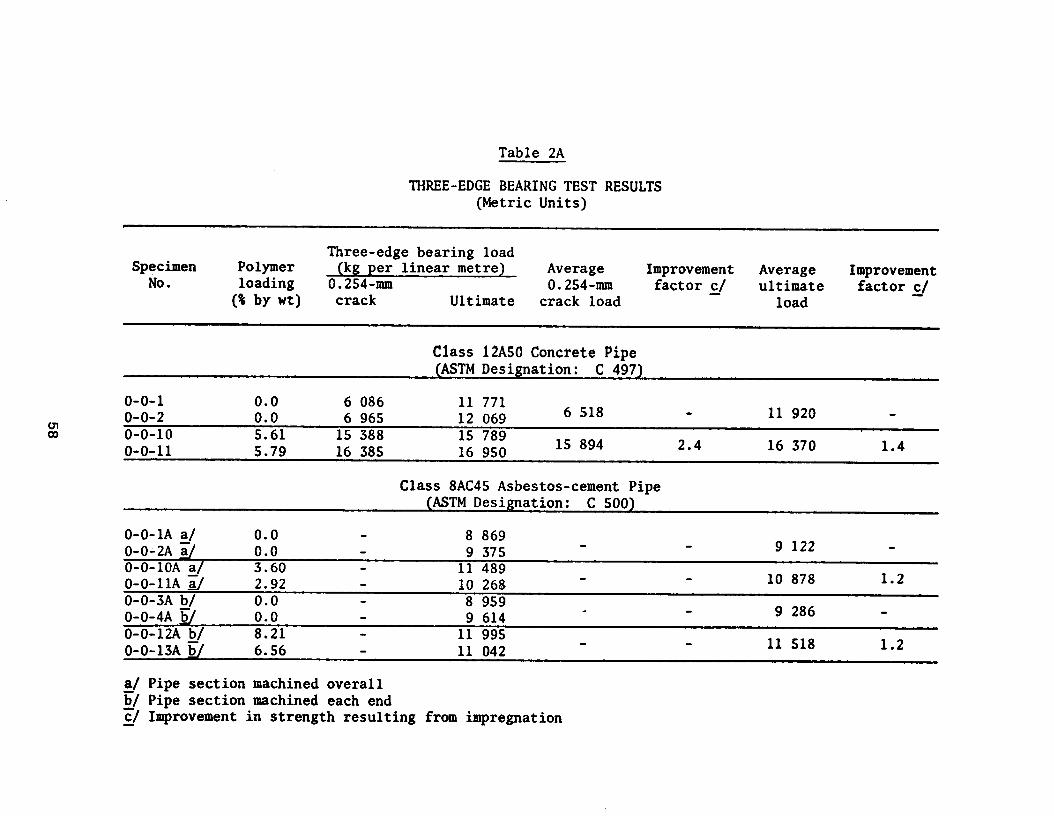
Table 2A
THREE-EDGE BEARING TEST RESULTS (Metric Units)
Three-edge bearing load Specimen Polymer (kg per linear metre) Average Improvement
loading Average
No. Improvement
0.254~mm 0.254~mm ultimate 0 by wt) crack Ultimate
factor j crack load
factor j load
Class 12A50 Concrete Pipe (ASTM Designation: C 497)
o-o-1 0.0 6 086 11 771 o-o-2 0.0 6 965 12 069 6 518 11 920 o-0-10 5.61 15 388 15 789 o-0-11 5.79 16 385 16 950 15 894 2.4 16 370 1.4
Class 8AC45 Asbestos-cement Pipe (ASTM Designation: C 500)
O-O-1A a/ 0.0 8 869 O-O-2A z/ 0.0 9 375 9 122 O-O-10A a/ 3.60 11 489 O-O-1lA 2 2.92 10 268 10 878 1.2 O-O-3A b/ 0.0 8 959 O-O-4A ii/ 0.0 9 614 9 286 O-O-12A b/ 8.21 11 995 O-O-13A Q 6.56 11 042 11 518 1.2
&/ Pipe section machined overall b/ Pipe section machined each end c/ Improvement in strength resulting from impregnation

llllllll
00000000 w0hlONwweJ m
M~ubObOt
* .
. .
u;w rc'w
UTW
6o'rw
I II
I I
I II
O~~%BOO~,"s
0 0
4 r;
d d
d d
x+~>P=
?;:a;$$%
00000000 11811,ll
00000000
59

Table 3
WATER ABSORPTION TEST ‘(AS’lM Designation: C 497, S-hour boiling method)
Specimen No.
Polyner loading
(s by a)
Decrease in absorption
(percent) fi/
Class 12ASO Concrete Pipe
o-o-1 0.0 6.06 o-o-2 0.0 6.22. o-0-10 5.61 0.55 91 c-o-11 5.79 0.44 93
Class 8AC4S Asbestos-cement Pipe
O-O-1A b/ O-O-2A r;/ 0-0-lOA-b/ O-O-1lA i;i o-o-3A CT 0-0-4A 71
K -o-m-c/ -t-I-13A E/
0.0 14.27 0:o 14.25 3.60 9.23 2.92 10.02 0.0 16.95 0.0 16.99 8.21 6.88 6-56 7.00.
a/ Percent decrease in absoiption resulting from impregnation 6/ Pipe section machined overall E/ Pipe section machined each end
60

Figure 1 .The assembled constant-head orifice canal turnout.
61


APPENDIX C
IMPREGNATION OF PIPE FOR GEOTHERMAL WELLS


ou CPYl (41 cm) 1014..
UNITED STATES GOVERNMENT
Memorandum TO
Memorandum Denver, Colorado : Head, Polymer Concrete and Structural Section DATE: May 19, 1975
FROM : Fred E. Causey, Chemical Engineer
SUBJECT: Impregnation of Pipe for Geothermal Wells
Introduction
Test sections of polymer-impregnated concrete and asbestos-cement pipe were proposed for installation at the Geothermal Facility near Holtville, California. Since the hot brine will be about 320' F (160' C), it was decided that a 60-40 styrene-TMPIMA (trimethylol- propane trimethacrylate) monomer system would be used to impregnate the pipe. Previous work showed this system had a compressive strength of about 11,000 lb/in2 (774 kg/cm2) at 350' F (177" C). Thus, the pipe sections were impregnated with the styrene-TMPRIA monomer system. Also some 6-inch by 12-inch (15.2-cm by 30.5-cm) cylinders were impregnated to check compressive strength.
Impregnation
Twenty-eight 12-inch-inside-diameter by 6-foot 3-S/8-inch (30.5- by 192.1-cm) concrete pipe sections and fifteen 8-inch-inside-diameter by 3-foot 3-inch (20.3- by 99-cm) asbestos-cement pipe sections and twelve 8-inch (20.3-cm) asbestos-cement pipe couplings were treated in seven impregnations. Several 6-inch by 12-inch (15.2-cm by 30.5-cm) cylinders were also impregnated to check compressive strength for each impregnation.
The concrete pipe sections were loaded into a large drying oven with a 4,000-pound (1,800-kg) capacity fork lift. Only one specimen was hauled from the yard to the oven at a time. Four pipe sections were stacked into the oven for each impregnation. Figures 1 and 2 show loading and unloading of the oven and how the specimens were stacked in the oven. The asbestos-cement pipe sections and couplings were brought in from the yard in groups of four at a time on the fork lift. These specimens were loaded and unloaded into a second oven shown in figure 3. These specimens were hand loaded. All sections and couplings were dried at 350" F (177' C) and cooled to room temperature as indicated in the table. The temperature was raised slowly as not to exceed 40' F (22“ C) per hour in the heat cycle and thus was SO regulated that it took 8 hours to reach 350" F (177' C). All specimens were cooled overnight.
The concrete pipe sections were weighed on a 375-kg-capacity scale, the asbestos-cement pipe sections were weighed on a 90-kg scale and
Buy U.S. Savings Bonds Replarlj on tbc Payroll Savings Plan
65

Figure -Loading and unloading of pipe in oven.
Figure 2. -Specimens stacked in oven.
66

couplings were weighed 5,000-g plus l,OOO-g-tare capacity scale. The concrete sections were placed on the scale as shown in figure 4, while other specimens were placed on scales by hand. All dried weights and impregnated weights are shown in table 1.
After weighing, the concrete pipe sections were stood on end by a lifting device (figure 5). Three sections were loaded bell down and one bell up for each impregnation, and 6-inch by 12-inch cylinders were placed between pipe sections to reduce the volume of monomer (figures 6 and 7). Asbestos-cement pipe sections were placed inside concrete pipe sections in the last four impregnations. Pipe couplings also were placed inside concrete pipe sections for impregnation. Figures 8 and 9 show the operations of closing and opening, and bolting and unbolting the top of the impregnator.
After the lid had been bolted on, the vacuum pump was switched on and 23 inches (584 mm) Hg [Denver mean 24.7 inches (627 mm) Hg] were drawn. While the vacuum cycle was in process the water jacket was filled with tap water (about 10' C). The water was then heated by steam for thermal-catalytic polymerization.
While the vacuum cycle was in progress, by styrene and trimethylol- propane trimethacrylate (TMPTMA), monomers catalyzed with one-half percent D-A79 (a-t-butylazo isobutzronitrile) were mixed by bubbling air through the transfer tank. The weight mix ratio of the monomer system was 60 percent styrene to 40 percent TMPTMA by weight.
After the vacuum cycle was completed, the catalyzed monomer was drawn into the impregnator from the transfer tank by the 23 inches of vacuum. When the proper monomer level was reached, the valve to the impregnator was closed and monomer left in the line was transferred back into the transfer tank with compressed air. After the monomer transfer was completed, the vent valve was opened to release the remaining vacuum. The impregnator was then slowly pressurized with compressed air to a pressure of 40 lb/in2n When pressure cycle was completed, the monomer was transferred back into the transfer tank. Compressed air was blown through impregnator and line to remove excess monomer before polymerization.
The impregnated pipe sections were submerged in water and polymerized. Warm water was transferred, using compressed air, from a large water heater into the impregnation-polymerization vessel. Temperature of the water brought in for each polymerization is given in table 1. The water in the water jacket was heated by steam, which heats the water in the vessel. The jacket water temperature was raised to 200' F (93' C) and the water around the pipe sections raised to 190' F (88" C). The steam was then shut off. The polymerization goes to completion
67


Figure 5. -Preparing to lift pipe to load into impregnator.
Figure 6. -loading pipe into impregnator.
69

Figure 7. -Pipe loaded in impregnator.
Figure 8. -Hoisting lid onto impregnator.
70

Figure 9. -Bolting lid on impregnator.
71

in a couple of hours. The water was drained the next morning, and compressed air was blown through to cool the specimens and remove the last of the water. The pipe sections were removed. Polymer loadings were calculated from the dried and impregnated weights. These data are shown in table 1.
Results
Polymer loadings for concrete pipe sections ranged from 5 to 6 percent, as was expected. The polymer loadings for the asbestos- cement pipe sections and couplings were somewhat variable and generally lower than expected, ranging from 3 to 9 percent. Three sections having the very low loadings were of a different pipe finish. The asbestos-cement specimens may not be fully impregnated, possibly because of fine porosity which restricts the impregnation by a large diameter monomer molecule. Thus, a water absorption test should be conducted to see if water absorption has been reduced to justify use of this pipe in geothermal wells. The 6-inch by 12-inch 3 4 (15.2-cm by 30,..5-cm) cylinders were broken %n compression. The average compressive strength at room temperature-.-(220_o-,.~) was 17,590 lb/in2 (1,237 kg/cm2).
-_____. . .._... -.- . Table 1 shows polymer loadings and
table 2 shows compressive strengths.
72

Table 1. - Weights and Impregnation Cycles
Test 1
Four 12-inch-inside-diameter by 6-foot 3-S/8-inch section of concrete pipe dried 24 hours and cooled about 24 hours; 8 hours were used to reach 350" F. Impregnated with 60-40 styrene-TMPTMAL/and one-half percent D-A79-monomer temperature was about 62' F. 21
Cycle: l-hour vacuum at 23.5 inches Hg. 3-hour pressure at 40 lb/in2.
Polymerized under water overnight at 190' F and 0 lb/in2. Water came in at 120' F and dropped to 110' to 115' F.
Spec No.2' Dry wt wt Imp Poly wt % loading
HR-1 271.6 kg 286.45 14.85 5.47 HR-2 273.7 287.55 13.85 5.06 HR-3 272.3 286.85 14.55 5.34 HR-4 275.0 289.30 14.30 5.20
1. TMPTMA = trimethlolpropane trimethacrylate. 2. D-A79 = a-t-butylazo isobutyronitrile. 3. Spec No. = specimen number; Dry wt = dry weight; Imp wt - impregnated weight; Poly wt = polymer weight; kg = kilogram; and g = gram.
73

Test 2
Four 12-inch-inside-diameter by 6-foot 3-S/8-inch section of concrete pipe dried 24 hours and cooled about 24 hours; 8 hours were used to reach 350' F. Impregnated with 60-40 styrene-TMPTMA plus one-half percent D-A79 monomer temperature was about 65' F.
Cycle: l-hour vacuum at 23.5 inches Hg. 3-hour pressure at 40 lb/in2.
Polymerized under water overnight at 190' F and 5 lb/in2; water came in at 155' F and dropped to 145' F.
Spec No. wt Dry wt Imp Poly wt X loading
HR-5 269.80 kg 285.60 15.80 5.86 HR-6 273.15 287.40 14.25 5.22 RR-7 271.20 286.30 15.10 5.57 RR-8 273.25 287.60 14.35 5.26
6-inch by 12-inch cylinders
DT-27 12.65 kg 13.23 0.58 4.58 DT-14 12.85 13.49 0.64 4.98
74

Test 3
Four 12-inch-inside-diameter by 6-foot 3-S/8-inch sections of concrete pipe dried 24 hours and cooled about 24 hours; 8 hours were used to reach 350' F. Impregnated with 60-40 styrene-TMPTMA plus one-half percent D-A79 monomer temperature was about 65' F.
Cycle : l-hour vacuum at 23 inches Hg. 3-hour pressure at 40 lb/in2.
Polymerized under water overnight at 190' F and 15 lb/in2; water came in at 180' F and dropped to 170' F.
Spec No. Dry wt Poly wt X loading
HR-9 271.45 kg 286.60 15.15 5.58 HR-10 271.00 286.20 15.20 5.61 RR-11 270.10 286.10 16.00 5.92 HR-12 269.80 286.00 16.20 6.00
6-inch by 12-inch cylinders
DT-43 12.57 kg 13.22 0.65 5.17 DT-39 12.67 13.30 0.63 4.97
75

Test 4
Four 12-inch-inside-diameter by 6-foot 3-5/8-inch sections of concrete pipe, 4-inch to 8-inch-inside-diameter by 3-foot 3-inch sections of asbestos-cement pipe, and 4-inch to 8-inch asbestos-cement pipe couplings dried 24 hours and cooled over the weekend; 8 hours wereused to reach 350' F. Impregnated with 60-40 styrene-TMPTMA plus one-half percent D-A79 monomer temperature was about 38' F.
Cycle: l-hour vacuum at 23 inches Hg. 3-hour pressure at 40 lb/in2.
Polymerized under water overnight at 190' F and 5 lb/in2; water came in at 115' F and dropped to 105' F.
Spec No. wt Dry
HR-13 HR-14 HR-15 HR-16
274.15 kg 269.70 273.75 270.25
Asbestos
AHR-1 18.82 kg 19.35 0.55 2.92 2 18.08 19.40 1.32 7.30 3 16.88 18.52 1.64 9.72 4 18.53 19.08 0.55 2.96
Couplings
ACHR-1 4,977.2 g 5,238.5 261.3 5.25 2 4,767.6 5,096.O 328.4 6.89 3 4,999.2 5,402.3 403.1 8.06 4 4,997.g 5,321.5 323.6 6.47
wt Imp
288.00 285.30 287.15 285.65
6-inch by 12-inch cylinders
DT-34 12.68 kg 13.32 0.64 5.05 DT-60 12.62 13.29 0.67 5.31
Poly wt
13.85 15.60 13.40 15.40
% loading
5.05 5.78 4.89 5.70
76

Test 5
Four 12-inch-inside-diameter by 6-foot 3-S/8-inch sections of concrete pipe, 4-inch to 8-inch-inside-diameter by 3-foot 3-inch sections of asbestos-cement pipe and 4-inch to 8-inch asbestos-cement pipe coupling dried over the weekend at 350" F and cooled about 24 hours; 8 hours were used to reach 350" F. Impregnated with 60-40 styrene- TMPTMA plus one-half percent D-A79 monomer temperature 33' F.
Cycle: l-hour vacuum at 22.8 inches Hg. 3-hour pressure at 40 lb/in2.
Polymeiized under water overnight at 190" F and 5 lb/in2; water came in at 150' F and dropped to 135" F.
Spec No.
HR-17 HR-18 HR-19 HR-20
Asbestos
AHR-5 17.90 kg 19.14 1.24 6.93 6 18.32 18.98 0.66 3.60 7 18.24 18.87 0.63 3.45 8 17.87 19.17 1.30 7.27
Couplings
ACHR-9 4,779.4 g 5,077.2 297.8 6.23 10 4,733.3 5,061.O 327.7 6.92 11 4,912.g 5,171.2 258.3 5.26 12 4,999.l 5,268.0 268.9 5.38
Dry wt
276.90 kg 273.30 270.80 274.20
Imp wt Poly wt % loading
290.75 13.85 5.00 288.60 15.30 5.60 286.15 15.35 5.67 288.10 13.90 5.07
6-inch by 12-inch cylinders
DT-42 12.55 kg 13.20 0.65 5.18 DT-4 12.60 13.26 0.66 5.24
77
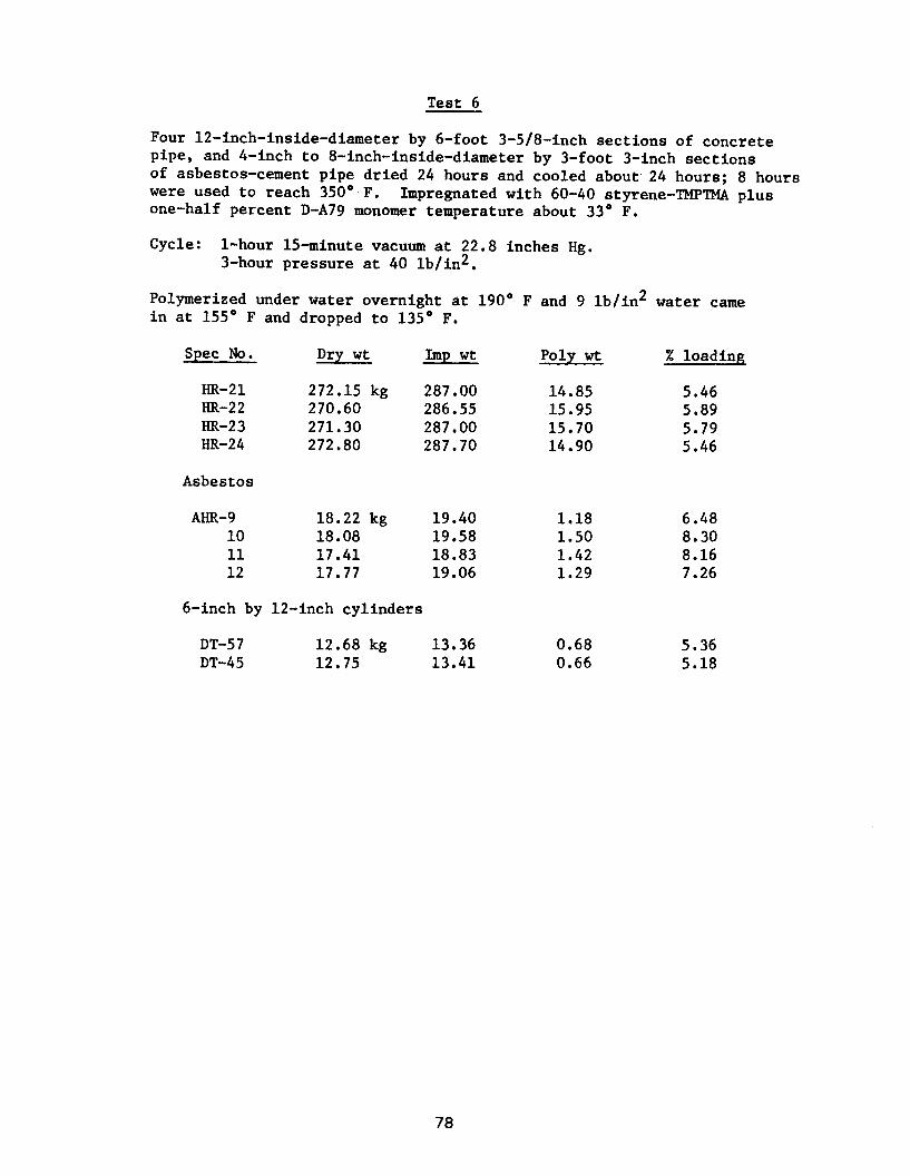
Test 6
Four 12-inch-inside-diameter by 6-foot 3-5/8-inch sections of concrete pipe, and 4-inch to 8-inch-inside-diameter by 3-foot 3-inch sections of asbestos-cement pipe dried 24 hours and cooled about. 24 hours; 8 hours were used to reach 350' F. Impregnated with 60-40 styrene-TMPTMA plus one-half percent D-A79 monomer temperature about 33' F.
Cycle: l-hour 15-minute vacuum at 22.8 inches Hg. 3-hour pressure at 40 lb/in2.
Polymerized under water overnight at 190' F and 9 lb/in2 water came in at 155" F and dropped to 135' F.
Spec No. Dry wt wt Imp Poly wt % loading
HR-21 272.15 kg 287.00 14.85 5.46 HR-22 270.60 286.55 15.95 5.89 HR-23 271.30 287.00 15.70 5.79 HR-24 272.80 287.70 14.90 5.46
Asbestos
AHR-9 18.22 kg 19.40 1.18 6.48 10 18.08 19.58 1.50 8.30 11 17.41 18.83 1.42 8.16 12 17.77 19.06 1.29 7.26
6-inch by 12-inch cylinders
DT-57 12.68 kg 13.36 0.68 5.36 DT-45 12.75 13.41 0.66 5.18
78

Test 7
Four 12-inch-inside-diameter by 6-foot 3-5/8-inch sections of concrete pipe, 3-inch to 8-inch-inside-diameter by.3-foot 3-inch sections of asbestos-cement pipe, and 4-inch to 8-inch asbestos-cement pipe couplings dried 24 hours at 350' F and cooled about 24 hours; 8 hours were used to reach 350' F. Impregnated with 60-40 styrene-TMPTMA plus one-half percent D-A79 monomer temperature was about 26' F.
Cycle: l-hour 15-minute vacuum at 22.8 inches Hg. 3-hour pressure at 40 lb/in*.
Polymerized under water overnight at 190" in at 135" F and dropped to 120' F.
Spec No.
HR-25 HR-26 HR-27 HR-28
wt Dry
271.25 kg 271.65 269.75 269.45
Imp wt
286.65 290.75 285.10 285.40
Poly wt % loading
15.40 5.68 19.10 7.03 15.35 5.69 15.95 5.92
Asbestos
AHR-13 17.92 kg 19.27 1.35 7.53 14 17.90 19.37 1.47 8.21 15 18.15 19.34 1.19 6.56
Couplings
ACHR-5 4,999.4 g 5,333.3 6 4,900.g 5,222.l 7 4,940.o 5,257.5 8 4,813.0 5,104.8
333.9 6.68 321.2 6.55 317.5 6.43 291.6 6.06
6-inch by 12-inch cylinders
TP-5 13.49 kg 14.08 0.59 4.37 6 13.38 13.98 0.60 4.48 9 13.52 14.10 0.58 4.29
F and 10 lb/in 2 ; water came
79

Table 2. - Compressive Strength of 6-inch by 12-inch (15.24-cm by 30.48-cm) Cylinders
Spec No. 1 Load Compressive Strength
lb. kg - lb/in2 kg/cm2
DT-14 460,000 208,650 16,270 1,144
27 482,000 218,630 17,050 1,199
39 513,000 232,690 18,150 1,276
43 501,000 227,450 17,720 1,247
34 539,000 227,450 19,070 1,340
60 501,000 227,450 17,720 1,247
4 492,000 223,170 17,400 1,224
42 517,000 234,510 18,290 1,286
45 529,000 239,950 18,710 1,316
57 523,000 237,230 18,500 1,301
TP- 5 477,000 216,360 17,040 1,198
6 468,000 212,280 16,710 1,175
9 449,000 203,660 16,040 1,127
1. DT specimens have a surface area of 28.27 in2 (182.38 cm2) for compressive strength; TP specimens have a surface area of 28.0 in2 (180.64 cm2).
80

APPENDIX D
EXPERIMENTAL REPAIR OF SHADOW MOUNTAIN DAM SPILLWAY

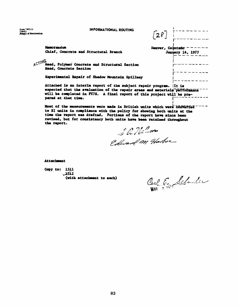
Mm WV-11 iNFORMATIONAL ROUTING I m-61) -----___ PDvrp ot RoG~loo
---- --
M8uratdum Chief,Concreu andStructural Branch
Denver, Co&zlu------ Jeuqary 14, 1977
Bud, concrete section
BkpuiunW BepaIr of
Attach4 ia an iaterb
i and Structur8l section t----- -----
shadov Houatdn spillway i ---m--e--- report of the 8ubjectrepairproSram. [It I.8 --- expected that the errlrution of the rep&r umm and uterialq perfo-i&fikii--'
vlllbe capleted in PY78. pue4irtthattime.
A final report of t&i8 project vi41 be pre- I--- -------_-
Mo*t of the mea8 L uremnts ware made in Britfmh unite which were -Z&Tii~~---' to SI unite incoqliaucevith thepolicy forshmlngbothrmita at the time the nportvudraftad. Portboa of the reporthme8fncebeen rmhmd,butforconaistencybothunlUhavebmn rotahed throughout the report.
Attachnnt
copy to: I.511 A2
(vith attachvent to each)
83

EXPERIMENTAL REPAIR OF SHADOW MOUNTAIN DAM SPILLWAY
Interim Report
W. G. Smoak F. E. Causey G. W. DePuy T. E. Rutenbeck 0. R. Werner
INTRODUCTION
Shadow Mountain Dam is located on the Colorado River near Grand Lake, Colorado. The crest of the spillway is at elevation 2544 m (8,348 ft) above sea level and is subjected to the typical cli- matic exposure conditions of the Rocky Mountains, ranging from sub- zero temperatures and heavy snows in the winter to warm and sunny days in the summer with occasional mountain rain showers. Construc- tion of the dam and spillway was completed in 1946.
On June 13, 1973, Messrs. Smoak, Causey, Rutenbeck, and DePuy accom- panied by Charles Calhoun and Lowell Crow of the Lower Missouri Region Office, met with Bob Murray, Western Slope Manager, and Zenas Blevins and Paul Roosa from the Loveland Project Office at Shadow Mountain Dam and inspected the spillway as a possible site for experimental spillway repairs. The spillway floor showed some surface deterioration from freezing and thawing and possibly some minor damage from rocks thrown over the side by tourists. The deterioration is unsightly, but does not present an immediate threat to the structural integrity of the spillway. As there was no immediate need for a per- manent repair of the spillway, this was an excellent opportunity to test experimental repair and protective systems and obtain several years' exposure to evaluate their field performance. It was anticipated that a permanent repair would be made at a later time using one of the systems proven acceptable in these tests.
EXPERIMENTAL REPAIR PROGRAM
During the inspection of the damaged portions of the spillway, it was determined that freeze-thaw damage was also occurring beneath epoxy mortar patches that had previously been placed. This damage caused disbonding of the patches and failure of the patch as a repair technique.
In laboratory durability tests, polymer impregnated concrete has shown greatly improved freeze-thaw resistance over conventional concrete
84

SURFACE IMPREGNATION
EPOXY OVERLAY APPLIED ON DAMP CONCRETE SURFACE
t
I d
EPOXY OVERLAY NO. 3
I T- I
EPOXY OVERLAY
I NO. 2 I 1 I I I EPOXY OVERLAY
LYJ
P.C. OVERLAY
I
L ---
r---- l I I
i I I COATINGS
I
I I
I
I
I
\
WATER FLOW
Figure 1. - Sketch shows schematic layout for the experimental repairs on the floor of the Shadow Mountain Spillway.
85

Figure 2. -Spillway area selected for experimental repairs.has been sandblasted in preparation for overlays.
Area
86

Figure 4. -The drying enclosure has been completely installed andis shown in operation during the drying of the spillway floor.
87

(TMPTMA). In the mixing operation, the proper weights of the respec- tive monomers were added to a container and mixed by bubbling low- pressure compressed air into the container. The mixed monomer was then placed in standard drums and transported to the jobsite. At the spillway and just prior to use, the polymerization catalyst, 2,2 azobis (2,4 dimethylvaleronitrile), was added to the monomer system. Mixing was accomplished with low-pressure compressed air (fig. 6).
Due to the monomer system's sensitivity to solar radiation, monomer application to the spillway was done at night. Previous experience with this monomer system has shown that an application rate of approx- imately 7.3 kg/m2 (1.5 lb/ft2) applied in two applications, 4 to 5 hours apart, yields the desired polymer penetration. For the first application, the polymerization catalyst was added to the monomer at the concentration of 0.5 wt percent. After mixing, the monomer system was applied to the sand with sprinkling cans (fig. 7). The initial ap
5 lication was made at the rate of approximately 4.9 kg/m2
(1.0 lb/ft ) which was sufficient to fully saturate the sand. The wet surface was then covered with polyethylene plastic to reduce monomer evaporation and left to soak for 4 hours. A second application of monomer was then made at the rate of 2.4 kg/m2 (0.5 lb/ft2), again fully saturating the sand.
The treated area was then recovered with polyethylene plastic and the enclosure with its related heating and control equipment rein- stalled on the spillway (fig. 8). Soaking was allowed to continue for an additional 5 hours before the heaters were turned on to begin the polymerization cycle.
Prior to turning on the heater burners, the heater fans were turned on to clear the enclosure of flammable monomer vapors. When the enclosure was safely ventilated, the heater burners were turned on and the concrete surface temperature slowly increased to 77°C (170'F) over a period of about 10 hours. This temperature, +lO'C (20°F), was then maintained for an additional 14 hours.
At the completion of the polymerization cycle, the heat was turned off and the enclosure removed from the treatment area. Most of the sand used as a monomer reservoir during impregnation and polymeriza- tion could be swept from the surface. In one area (fig. 9) the sand was tightly bonded to the concrete and was removed by sandblasting and chipping (fig. 10).
Five SO-mm (2-in.) diameter core specimens were subsequently drilled from the impregnated area and broken in tensile splitting to determine the polymer penetration. These specimens showed visible polymer penetrations of 13 to 38 mm (l/2 to l-1/2 in.).
88

Figure 7. -Monomer is applied to concrete surface at night to avoid
premature polymerization initiated by sunlight. Sprinkler cans werea convenient means for'applying monomer to the relatively smalltreatment area.
89

Figure 9. -The surface-impregnated area is shown after completionof the polymerization cycle. The irregular-shaped patch was formedby sand bonded to the concrete by excess polymer.
90

The surface impregnation equipment was then removed from the test slab in preparation for placement of the PC and epoxy mortar experi- mental repair overlays.
PC Overlay
A PC overlay was placed on an area 2.1 by 6.1 m (7 by 20 ft) as shown in figure 1. Approximately one-half of the area overlaid, 2.1 by 3.0 m (7 by 10 ft), had received the surface impregna- tion treatment. Rain had fallen during the night prior to overlay application and the moisture was dried from the surface using two 530-MJ (500,000-Btu) space heaters as shown in figure 11. Water which leaked by the seals of the spillway gates during the overlay application was diverted by dikes made from a fast-setting cement.
PC Materials
A vinyl ester resin manufactured by Dow Chemical Company with a trade name of Derakane 470 was mixed with a graded aggregate to form PC for the overlay.
The vinyl ester resin was preweighed in Denver. l’wo promoters, cobalt naphthenate and dimethyl aniline, were added to the resin during this operation. Methylethyl ketone peroxide, the catalyst, was preweighed into small bottles for mixing when needed at the jobsite. The monomer system formula on a mass basis was:
PC Monomer System
Derakane 470 - vinyl ester resin 100 parts cobalt naphthenate - promoter 0.2 parts dimethyl aniline - promoter 0.05 parts methylethyl ketone peroxide - catalyst 0.5 parts
The monomer system was mixed with the aggregate in a ratio of about eight parts graded aggregate to one part monomer system by mass.
Graded sand for making the PC was preblended in Denver. The sand was batched in large cans holding 20 kg (45 lb) each with the aggre- gate graded as shown in the following chart:
91
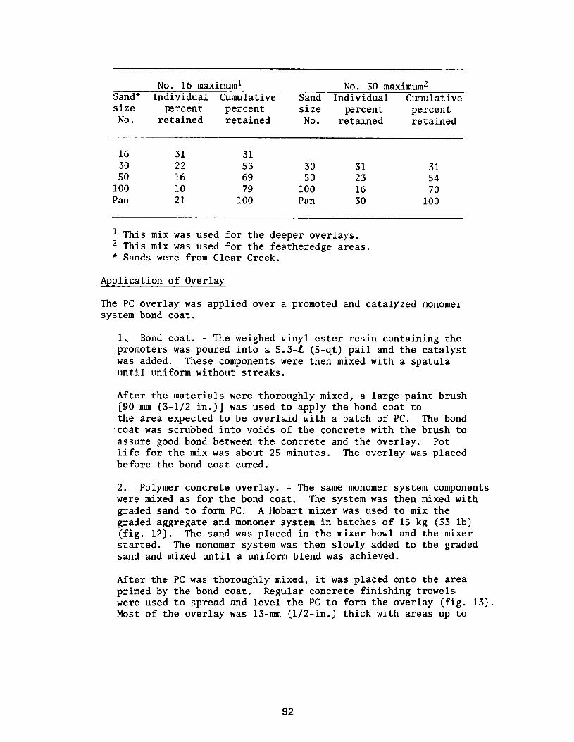
No. 16 maximum1 No. 30 maximum2 Sand* Individual Cumulative Sand Individual Cumulative size percent percent size percent percent No. retained retained No. retained retained
16 31 31 30 22 53 30 31 31 50 16 69 50 23 54
100 10 79 100 16 70 Pan 21 100 Pan 30 100
1 This mix was used for the deeper overlays. 2 This mix was used for the featheredge areas. * Sands were from Clear Creek.
Application of Overlay
The PC overlay was applied over a promoted and catalyzed monomer system bond coat.
1 Bond coat. - The weighed vinyl ester resin containing the p;omoters was poured into a 5.3-L (S-qt) pail and the catalyst was added. These components were then mixed with a spatula until uniform without streaks.
After the materials were thoroughly mixed, a large paint brush [90 mm (3-l/2 in.)] was used to apply the bond coat to the area expected to be overlaid with a batch of PC. The bond coat was scrubbed into voids of the concrete with the brush to assure good bond between the concrete and the overlay. Pot life for the mix was about 25 minutes. The overlay was placed before the bond coat cured.
2. Polymer concrete overlay. - The same monomer system components were mixed as for the bond coat. The system was then mixed with graded sand to form PC. A Hobart mixer was used to mix the graded aggregate and monomer system in batches of 15 kg (33 lb) (fig. 12). The sand was placed in the mixer bowl and the mixer started. The monomer system was then slowly added to the graded sand and mixed until a uniform blend was achieved.
After the PC was thoroughly mixed, it was placed onto the area primed by the bond coat. Regular concrete finishing trowels. were used to spread and level the PC to form the overlay (fig. 13). Most of the overlay was 13-mm (l/2-in.) thick with areas up to
92
19-mm (3/4-in.) thick where more extensive freeze-thaw spalling had occurred. After several square feet of overlay were com- pleted, a sheet of polyethylene was laid over the overlay and a water-filled lawn roller was used for final compaction and level- ing (fig. 14). The overlay cured hard to the touch in l/2 to 1 hour after being placed.
Vinyl Ester Polymer Coating
An area about 1.5 by 1.2 m (5 by 4 ft) was coated with the vinyl ester monomer system to determine whether it would provide protection to the spillway concrete against future freeze-thaw deterioration. Part of the area, about 0.6 by 1.2 m (2 by 4 ft) was sandblasted and dried. The remaining area, about 0.9 by 1.2 m (3 by 4 ft), was broom cleaned and dried. A go-mm (3-l/2-in.) paint brush was used to scrub the monomer system into the surface of the concrete.
PC Curing
The overlay was hard to the touch in l/2 to 1 hour after being placed and the finish, although splotchy from the individual batches, appeared good. On inspection, after an overnight cure, a few hairline shrinkage cracks were apparent in the surface of the overlay in areas where the mix was slightly rich in the monomer system.
Epoxy Mortar Overlays
Epoxy mortar overlays were prepared with three epoxy resins as follows:
1. Sikadur Lo-Mod is a two-component, 100 percent solids, poly- amide epoxy resin manufactured by Sika Chemical Corporation. Because this resin is a po,lyamide epoxy, it does not meet the requirements of Federal Specification MMM-B-350B for Flexible Epoxy Resin Adhesive Binder. Sikadur Lo-Mod was chosen because the manufacturer claims that it can be applied in cool weather [4"C (40°F)] to damp concrete without appreciable loss of ultimate bond strength. Sikadur Lo-Mod epoxy resin was mixed as recommended by the manufacturer? combined with sand meeting Bureau specifications requirements, and applied to both damp and dry concrete. The temperature of the repair area during and after application of the epoxy mortar varied greatly with the radiation of the sun during the day and the cool weather at night.
2. Sinmast Rapid Cure Mortar Mix Resin, another two-component, 100 percent solids, polyamide epoxy resin, is marketed by Sinmast of America and also does not meet requirements of the Federal
94
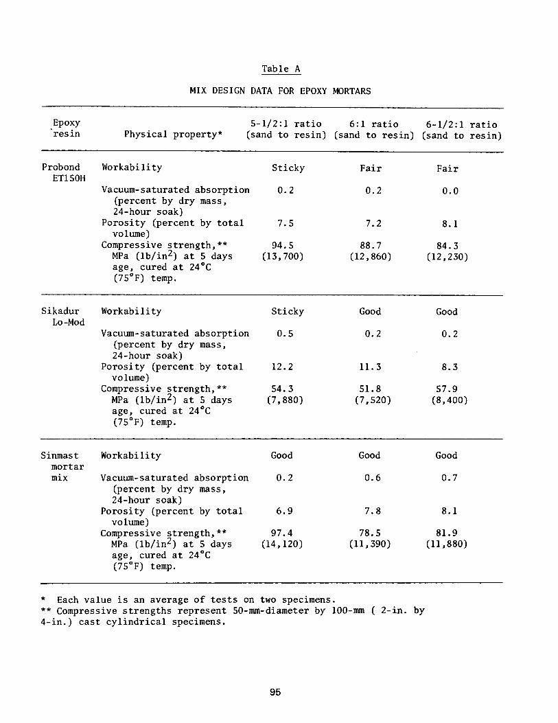
Table A
MIX DESIGN DATA FOR EPOXY MORTARS
Epoxy 5-l/2:1 ratio 6:l ratio ‘resin
6-l/2:1 ratio Physical property* (sand to resin) (sand to resin) (sand to resin)
Probond Workability Sticky Fair Fair ETlSOH
Vacuum-saturated absorption 0.2 0.2 0.0 (percent by dry mass, 24-hour soak)
Porosity (percent by total 7.5 7.2 8.1 volume)
Compressive strength,** 94.5 88.7 84.3 MPa (lb/in2) at 5 days (13,700) (12,860) (12,230) age, cured at 24'C (75'F) temp.
Sikadur Workability Sticky Good Good Lo-Mod
Vacuum-saturated absorption 0.5 0.2 0.2 (percent by dry mass, 24-hour soak)
Porosity (percent by total 12.2 11.3 8.3 volume)
Compressive strength,** 54.3 51.8 57.9 MPa (lb/in2) at 5 days (7,880) (7,520) (8,400) age, cured at 24'C (75OF) temp.
Sinmast Workability Good Good Good mortar mix Vacuum-saturated absorption 0.2 0.6 0.7
(percent by dry mass, 24-hour soak)
Porosity (percent by total 6.9 7.8 8.1 volume)
Compressive strength,** 97.4 78.5 81.9 MPa (lb/in2) at 5 days (14,120) (11,390) (11,880) age, cured at 24OC (75'F) temp.
* Each value is an average of tests on two specimens. ** Compressive strengths represent SO-mm-diameter by loo-mm ( 2-in. by 4-in.) cast cylindrical specimens.
95
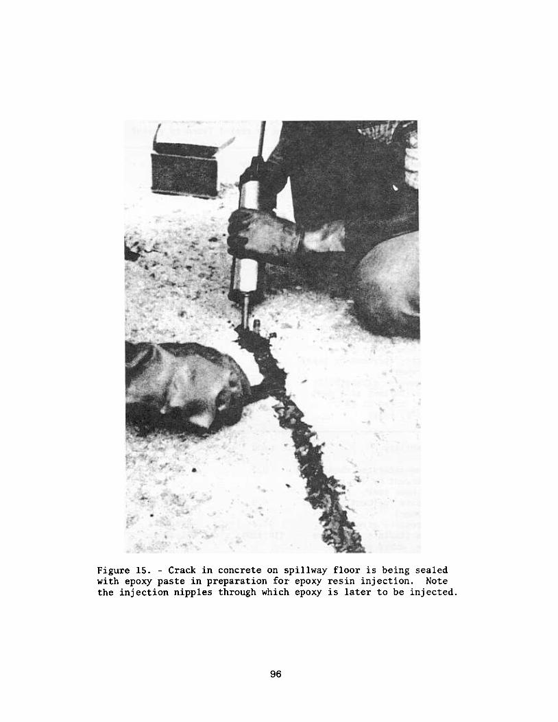
Figure 15. -Crack in concrete on spillway floor is being sealedwith epoxy paste in preparation for epoxy resin injection. Notethe injection nipples through which epoxy is later to be injected.
96

2. After placement of the mortar overlay was complete, no effort was made to cure the epoxy at an elevated temperature. However, the mortar lay exposed to direct sunlight and to very cool nights. The exposure of the dark mortar surface to the afternoon sun immediately after placing gave the overlay a brief, high tempera- ture cure [exceeding 45°C (113°E)] which was then followed by exposure to nighttime temperatures below O°C (32’F).
Figures 16 through 20 are a sequence of photographs taken throughout the application of the mortar overlays.
The Sinmast and Sika epoxy bond coats were applied at a coverage of approximately 1.60 m2/L (65 ft2/gal). The Probond was more viscous, so its bond coat was thicker, about 1.35 m2/e (55 ft2/gal). When the Sika and Sinmast bond coats were applied to damp surfaces, the resin became milky in appearance. However, the liquid resin still adhered well to the surface, and it seemed to mix well with the water.
All three epoxy mortars were applied at an average thickness of 10 mm (0.4 in.). The first few batches of each epoxy mortar overlay were mixed at proportions chosen during preliminary investigations. However, the mortar appeared to have excessive epoxy resin during finishing of the mortar surface. This excess may have been caused in part by bleeding of the bond coats through the thin mortar layers. Thereafter, the mortar mix proportions were adjusted for better workability. The major portions of the epoxy mortar overlays con- tained sand to epoxy ratios, by weight, of 6.9:1, 6.2:1, and 6.5:1 for the Probond, Sika, and Sinmast mortars, respectively.
Probond epoxy-bonded mortar was fairly difficult to finish compared to the other two epoxies used. From the time the Probond resin was first mixed, mortar could be worked effectively with a trowel for only 15 to 25 minutes. ,The short pot life may be due in part to use of a cold weather epoxy intended for use at temperatures below 20°C (68’P) on a concrete surface that was warmer than expected. The Probond epoxy mortar also had a tendency to stick to the trowels, thus making trowel- ing difficult.
Sika and Sinmast mortars, on the other hand, were very workable compared to the Probond product. These two mortars were easily screeded, could be effectively troweled using a typical sweeping motion with the trowel, and had a “pot life” of about 1 hour after mixing. However, bulges appeared on the surface of both Sika and Sinmast epoxy mortar overlays, while the mortar.was still plastic. These bulges grew slowly after troweling to a maximum visible diameter of approximately 40 mm (l-1/2 in.) and to a height of up to 5 mm (3/16 in.). These blisters occurred over the entire surface of the overlays and, therefore, do not appear to be caused by the water in the damp-surface.overlay section or prevented by the polymer impregnated overlay section.
97

Figure 17.volume.
-Sand was most easily measured by mass rather than by
98

Figure 19. -Epoxy mortar is being screeded over the freshly placedepoxy bond coat on the concrete surface. Note the milky appearanceof the epoxy resin bond coat, which is caused by the presence ofwater on the concrete surface.
99

One-month Inspection
About 1 month after the repairs had ,been completed, they were inspected. The appearance of the PC had not changed. The Sinmast mortar was pattern cracked over the entire surface as shown in figure 21. The Probond and Sika mortars appeared to be free from significant surface cracking. Cores were extracted during the l-month inspection to evaluate the epoxy mortar and PC overlays, epoxy injection yepair, and to determine the depth of monomer impregnation. NX-size cores were extracted from all three epoxy overlays and from the PC overlay.
Several of the NX cores were drilled through the surface bubbles which had appeared as previously described in two of the epoxy overlays immediately after troweling. Also, 75-mm (3-in.) diameter cores were extracted from the concrete containing the crack repaired by epoxy injection.
In all but one core, which was extracted from badly cracked epoxy mortar, the overlays were bonded well enough to the concrete to enable core extraction without disbonding at the concrete-overlay interface. The llbubblesll found in two of the epoxy mortars had a poorly defined hollow center apparently created by expanding gas.
Nine-month Inspection
About 9 months after the repairs had been completed, the PC and all three epoxy mortar overlays were checked for bonding, cracking, and hardness. During that 9 months, the repairs had been exposed to the winter cycle, and water had been flowing about 1 week in the spillway due to the onset of spring runoff.
The vinyl ester PC overlay appeared to be in good condition. Some small hairline pattern cracks were observed on the overlay. These were similar to those observed when the overlay was first installed. The cracks are more prominent along the southern and northern portions of the overlay. The cracks do not present a serious problem at this time, but should be closely observed over the next few years.
The overlay was tapped with a hammer to locate hollow-sounding, loose, or poorly bonded areas. Two small poorly bonded areas were detected: one area was 250 mm (10 in.) in from the downstream edge of the over- lay and 3.3 m (10 ft 10 in.) from the south edge; the other was 230 mm (9 in.) in from the upstream edge and 4.0 m (13 ft 3 in.) from the south edge. The loose areas appeared to be roughly 250 mm (10 in.) in diameter. The loose area on the upper edge was chipped
100

out. The cause for the loose areas is possibly deteriorated con- crete immediately below the overlay, but may be related to a very thin overlay thickness less than 6 mm (l/4 in.) and unsatisfactory mixing equipment used to prepare the PC. A crack located 300 mm (12 in.) north of the chipped out area was left intact for continued observation.
The loose areas were in the part of the spillway not surface impregnated. The remainder of the PC overlay over the area not surface impregnated and the entire PC overlay over the surface impregnated area appeared sound and well-bonded to the concrete. Therefore, it appeared that there may be a definite benefit from surface impregnation in providing good bond and perhaps in strengthening weak areas of the concrete.
An area treated by surface-impregnation only and an area treated by application of vinyl ester monomer system only appeared to be in good condition. These areas were wet, and cracking could not be observed.
The three epoxy mortar overlays were checked for bonding, cracking, and hardness.
Bonding
A geologistls hammer was used to locate drummy sounding areas. Both the mortar made with Probond epoxy and the mortar made with Sika epoxy were sound (not drummy) over about 98 percent of the area. Each contained isolated drummy spots of very small area [less than 0.1 m2 (1 fG)J. On the downstream edge of the Probond overlay, 2.4 m (92 in.) from the edge of the overlay nearest the wall, a small drummy area was probed with a geologist's hammer. Mortar in this area had been applied in two layers, the second layer being placed soon after the first. As the first layer was assumed to be still plastic when the second layer was placed, a bond coat was not used between the first and the second layer of mortar, but these two layers had disbonded. Removal of the lower layer of mortar revealed failure in the concrete rather than disbonding at the bond coat.
The Sinmast epoxy mortar overlay was drummy over much of its area. While drummy areas appeared to be randomly located on the other two overlays, drummy areas found on the Sinmast mortar overlay were more prevalent over the nonimpregnated concrete. Sinmast mortar that had been applied over dry, impregnated concrete was sound, while Sinmast mortar applied over wet, impregnated concrete was drummy in several small areas. Over the moist, nonimpregnated concrete, about 70 percent of the Sinmast mortar was drummy, while about 25 percent was drummy where applied over the dry nonimpregnated concrete. A small piece
101

Discussion of Experimental Repair Failures
1. Epoxy injection. - The epoxy injection resin failed to fill the finest portion of the crack in the spillway floor. Cracks of this width [about 0.2 mm (0.008 in.)] have been successfully injected in the past. Injection pressure used at Shadow Mountain [350 kPa (50 lb/in2)] should have been sufficient to inject a crack of this width. Cores taken after injection, however, revealed that the crack was not filled with epoxy. It is likely that during the drilling of holes for installation of injection nipples, dust from the drilling operation sealed the crack at the injection points.
2. Blistering of epoxy mortars. - Bubbles which formed after troweling the two slower-setting epoxy mortars were apparently the result of the expansion of entrapped air. As the Bureau has experi- enced similar blisters caused by high temperature curing prior to sufficient set of mortar, it is likely that the temperature rise brought about by the sun’s radiation on freshly repaired surface caused the swelling of entrapped air in concrete just below the epoxy-concrete interface of air entrapped in the epoxy mortar mix. The temperature of one of the overlays within several hours after placement was found to be rather high at about 48°C (118’F). As troweling had effectively sealed the surface of the mortar, there would have been no means of escape for expanding gas.
CONCLUSIONS
The described method of installing nipples for injecting epoxy resin was inadequate for the narrow portion of the crack on the spillway floor. Future procedure for injection into narrow cracks should provide a means of preparation which does not inadvertently plug the crack and which exposes a sufficient length of crack to allow for a reasonably rapid injection rate.
The PC overlay appeared to have performed adequately for the g-month period. Poor control of the mixing procedure is believed responsible for the surface cracks.
The epoxy overlays which were applied to damp concrete seemed to be as well bonded as those applied to dry concrete. Small pieces of mortar removed during the g-month inspection indicate that areas where the mortar was drummy were caused by failure in the underlying concrete, not in the epoxy bond coat.
Sunshades and other methods should be used as needed to control blistering of fresh epoxy mortar.
102

Mission of the Bureau of Reclamation
The Bureau of Reclamation of the U.S. Department of the Interior is responsible for the development and conservation of the Nations water resources in the Western United States.
The Bureau’s original purpose “to provide for the reclamation of arid and semiarid lands in the West” today covers a wide range of interre- fated functions. These include providing municipaland industrial water supplies; hydroelectric power generation; irrigation water for agricul- ture; water quality improvement; flood control; river navigation; river regulation and control; fish and wildlife enhancement; outdoor recrea- tion; and research on water-related design, construction, materials, atmowheric management, and wind and solar power.
Bureau programs most frequently are the result of close cooperation with the U.S. Congress, other Federal agencies, States, local govern- men ts, academic institutions, water-user organizations, and other concerned groups.
” It describes some of the technical publications currently
obtained upon request from the Bureau of Reclamation, Attn D-922, P 0 Box 25007, Denver Federal Center, Denver CO 80225-0007.