uefa stadium lighting guide 2016 · uefa stadium lighting guide 2016 7 3 uefa illuminance levels it...
TRANSCRIPT
UEFA Stadium Lighting Guide
2016
UEFA Stadium Lighting Guide 2016
2
Contents
1 Introduction ............................................................................................................................................................................ 5
2 Design guide .......................................................................................................................................................................... 6
2.1 Main points .............................................................................................................................................................................. 6
3 UEFA illuminance levels ...................................................................................................................................................... 7
3.1 New stadiums ......................................................................................................................................................................... 7
3.2 Existing stadiums ................................................................................................................................................................. 7
3.3 Illuminance levels ................................................................................................................................................................ 7
3.4 Overview of illuminance levels for UEFA competitions ...................................................................................... 8
4 UEFA illuminance requirements ...................................................................................................................................... 9
4.1 Elite level A stadiums .......................................................................................................................................................... 9
4.2 Level A floodlighting illuminance.............................................................................................................................. 10
4.3 Level B floodlighting illuminance .............................................................................................................................. 11
4.4 Level C floodlighting illuminance .............................................................................................................................. 12
4.5 Level D floodlighting illuminance .............................................................................................................................. 13
5 Illuminance design guidelines ...................................................................................................................................... 14
5.1 Players and officials .......................................................................................................................................................... 14
5.2 Spectators ............................................................................................................................................................................ 14
5.3 Broadcasters and media ................................................................................................................................................. 14
5.4 Luminaire mounting positions .................................................................................................................................... 14
5.5 Floodlight luminaire mounting guide ...................................................................................................................... 15
6 Diagrams of design guidelines ..................................................................................................................................... 16
6.1 Corners – column/tower floodlight array ................................................................................................................. 16
6.2 Corners – linear floodlight array ................................................................................................................................. 17
6.3 Pitch perimeter – lateral distance ............................................................................................................................... 18
6.4 Pitch perimeter – luminaire mounting zone .......................................................................................................... 19
6.5 Pitch perimeter – second linear row .......................................................................................................................... 20
6.6 Luminaires’ focus point angle ...................................................................................................................................... 21
6.7 Pitch sides – luminaire mounting position ............................................................................................................. 22
6.8 Behind penalty area – luminaire mounting zone ................................................................................................. 23
6.9 Behind penalty area – luminaire mounting zone ................................................................................................. 24
6.10 Behind goal line – second linear row...................................................................................................................... 25
6.11 UEFA pitch dimensions .................................................................................................................................................. 26
7 Uniformity............................................................................................................................................................................. 27
8 Glare ....................................................................................................................................................................................... 28
8.1 Glare ........................................................................................................................................................................................ 28
8.2 Discomfort glare ................................................................................................................................................................ 28
8.3 Evaluation of glare ............................................................................................................................................................ 28
UEFA Stadium Lighting Guide 2016
3
9 Pitch illuminance switch mode (PISM) ...................................................................................................................... 29
9.1 Full match mode ................................................................................................................................................................. 29
9.2 Match continuity mode .................................................................................................................................................. 29
9.3 Training mode ..................................................................................................................................................................... 29
9.4 Maintenance mode .......................................................................................................................................................... 29
10 Flicker factor (FF) ............................................................................................................................................................. 30
10.1 Flicker factor guidance .................................................................................................................................................. 30
10.2 Flicker factor reference table ..................................................................................................................................... 31
10.3 Flicker factor with three-phase power supply .................................................................................................... 31
10.4 Flicker factor testing ...................................................................................................................................................... 32
10.5 12-point flicker factor test ........................................................................................................................................... 32
10.6 Flicker factor requirements by stadium illuminance level ............................................................................ 33
10.7 24-point flicker factor test .......................................................................................................................................... 33
10.8 Flicker factor test reference points – 12-point high-frequency test ........................................................... 34
10.9 Flicker factor test reference points – 24-point test ........................................................................................... 35
11 Minimum adjacent uniformity ratio (MAUR) ........................................................................................................ 36
11.1 MAUR on the horizontal plane ................................................................................................................................... 36
11.2 MAUR on the vertical plane ........................................................................................................................................ 37
12 Colour temperature ........................................................................................................................................................ 38
12.1 Colour temperature guide ............................................................................................................................................ 38
13 Colour rendering ............................................................................................................................................................. 39
14 Player shadows ................................................................................................................................................................ 42
15 Maintenance factor ........................................................................................................................................................ 44
16 Power supply .................................................................................................................................................................... 45
16.1 UEFA power supply requirements – elite level A ............................................................................................... 46
16.2 UEFA power supply requirements – level A ......................................................................................................... 47
16.3 UEFA power supply requirements – level B ......................................................................................................... 48
16.4 UEFA power supply requirements – level C ......................................................................................................... 49
16.5 UEFA power supply requirements – level D ......................................................................................................... 50
17 LED pitch perimeter display systems ....................................................................................................................... 51
18 TV broadcast camera plan ........................................................................................................................................... 52
18.1 Key to camera plan .......................................................................................................................................................... 53
19 Environmental guidance ............................................................................................................................................... 54
19.1 Environmental impact of illuminance ..................................................................................................................... 54
19.2 Environmental impact of glare .................................................................................................................................. 54
20 UEFA Pitch Illuminance Test Report introduction ............................................................................................... 55
UEFA Pitch Illuminance Test Report ............................................................................................................................... 56
Report template ..................................................................................................................................................................... 57
UEFA Stadium Lighting Guide 2016
4
Horizontal illuminance grid plan ....................................................................................................................................... 58
Vertical illuminance grid plan ............................................................................................................................................. 59
Illuminance test – pitch orientation plan ....................................................................................................................... 60
Summary of report data ......................................................................................................................................................... 61
Pitch illuminance power supply ......................................................................................................................................... 62
Measurement of illuminance ............................................................................................................................................... 63
21 Glossary of terms ............................................................................................................................................................ 64
UEFA Stadium Lighting Guide 2016
5
1 Introduction
This document contains a set of recommendations that have been developed in response to the many
requests that UEFA has received to provide detailed technical information on floodlighting levels and
assessment.
UEFA’s floodlighting requirements are listed in the UEFA Stadium Infrastructure Regulations, with further
stipulations in the respective competition regulations and manuals. For finals or final tournaments, the
staging agreements may include specific clauses regarding floodlighting.
These recommendations aim to help technical suppliers to meet these requirements. They also take into
account recent technological developments and broadcasting needs to support stadium owners who are
looking to install a high-quality system that is tailored to the current and anticipated future broadcasting
environment and UEFA’s competition requirements.
This lighting guide has been developed by UEFA in consultation with International Illuminance Services
(IIS) to encourage and ensure the adoption of best practices in pitch illuminance system design in all UEFA
stadiums.
UEFA Stadium Lighting Guide 2016
6
2 Design guide
This document provides guidelines for the artificial illuminance systems used for football pitches. The
principles applied to the design elements and how you apply these principles and combine them together
in one design will determine how successful your design is.
The following main points should be considered and applied when designing a new pitch illuminance system
or making alterations to an existing system.
2.1 Main points
1. It is essential that players’ comfort and performance are not hindered by the pitch illuminance system.
2. The ability of match officials to perform effectively should not be hindered by the pitch illuminance
system.
3. A spectator should be able to watch and enjoy the match without suffering any discomfort caused by
the pitch illuminance system.
4. The pitch illuminance system should provide a level of illuminance that enables television broadcasters
to operate effectively, in line with the requirements set out for the relevant UEFA illuminance level.
5. The relevant level of UEFA competition must be considered when assessing a stadium’s needs.
6. A successful pitch illuminance system will produce illuminance levels and uniformity that comply with
the requirements of the relevant UEFA illuminance level, with soft shadows where possible.
7. The pitch illuminance system must be reliable and effective for the given location. The specific
conditions that are relevant for the stadium location should be carefully assessed.
8. The pitch illuminance system should provide a long-term solution that is both efficient and cost-
effective.
9. The environmental impact of a pitch illuminance design solution should be carefully assessed. The
design team should be committed to achieving an environmentally responsible solution.
10. Every sports stadium is unique. Consequently, each stadium will require a design solution that is
appropriate for the relevant stadium and illuminance level.
11. The stadium’s infrastructure and design will have a significant impact on the type of pitch illuminance
system that can be applied. A four-corner tower/column system will not generally meet UEFA’s
requirements for illuminance level A stadiums.
12. Modern artificial lighting systems are able to provide high-quality illuminance conditions on the pitch
and may potentially be integrated into the architectural design of the stadium.
13. The artificial lighting system may also be used to create lighting effects for stadium events and
pre/post-match lighting effects.
14. A stadium lighting design should always take account of the latest technological requirements for
broadcast television.
15. A stadium lighting design should always assess the lighting equipment and technology that is available
and consider if it is appropriate for the desired lighting solution.
UEFA Stadium Lighting Guide 2016
7
3 UEFA illuminance levels
It is essential to ascertain the level of UEFA competition that the stadium is intended to be used for. The
pitch illuminance system should be designed to meet the requirements of the relevant UEFA illuminance
level. An illuminance system that operates to a higher specification than is necessary may be unduly
expensive to install and operate. In some situations, it may even be considered inappropriate given the
stadium’s size and location. However, it is also important that the design process gives due consideration to
long-term aspirations in terms of the intended use of the stadium. In some cases, it may be preferable to
comply with the requirements of a higher UEFA illuminance level to allow for future development.
Guidance in terms of the selection of the relevant UEFA illuminance level is provided in Section 3.4.
3.1 New stadiums
During the design process for new stadiums, this guide should be used for guidance to determine the level
of illuminance that is required. Once the installation of the illuminance system (i.e. floodlights) has been
completed, a UEFA illuminance test report should be submitted to UEFA for analysis. A template for that test
report can be found in Section 20.
3.2 Existing stadiums
Existing stadiums may want to evaluate their current illuminance system and ascertain how to meet the
standards required for the relevant level of competition.
Again, a UEFA illuminance test report should be completed and submitted to UEFA for analysis. Information
will be provided by UEFA with regard to the current illuminance conditions and any modifications that may
be required. A template for that test report is available to in Section 20.
3.3 Illuminance levels
The requirements in terms of the artificial illuminance of a football pitch are split into five illuminance levels.
The following table provides details of the recommended illuminance level for each competition round. If
there is any uncertainty as to which level applies, UEFA should be contacted for further guidance.
Stadiums and football grounds that are not intended to be used for TV broadcasts are not required to meet
the higher lighting requirements of levels A, B, C and D. However, the lighting conditions should still meet
the relevant sporting requirements of players, officials and spectators. The non-broadcast constitutes the
minimum requirements.
UEFA Stadium Lighting Guide 2016
8
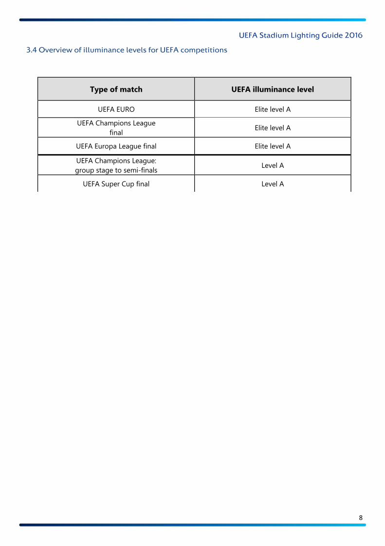
3.4 Overview of illuminance levels for UEFA competitions
Type of match UEFA illuminance level
UEFA EURO Elite level A
UEFA Champions League
final Elite level A
UEFA Europa League final Elite level A
UEFA Champions League:
group stage to semi-finals Level A
UEFA Super Cup final Level A
UEFA Women’s EURO Level B
UEFA European Under-21 Championship:
Final tournament Level B
UEFA Champions League:
Play-offs Level B
UEFA Europa League:
group stage to semi-finals Level B
UEFA European Football Championship:
qualifying matches Level B
UEFA Champions League:
third qualifying round Level C
UEFA Europa League:
third qualifying round and play-offs Level C
UEFA Champions League:
second qualifying round Level C
UEFA European Under-21 Championship:
qualifying matches Level C
UEFA Champions League:
first and second qualifying rounds Level D
UEFA Europa League:
First and second qualifying rounds Level D
Youth and Women’s Competitions:
Qualifying rounds, group-stage and knock-out
rounds (excluding final(s))
Level D
Non-broadcast matches 350 lux
UEFA Stadium Lighting Guide 2016
9
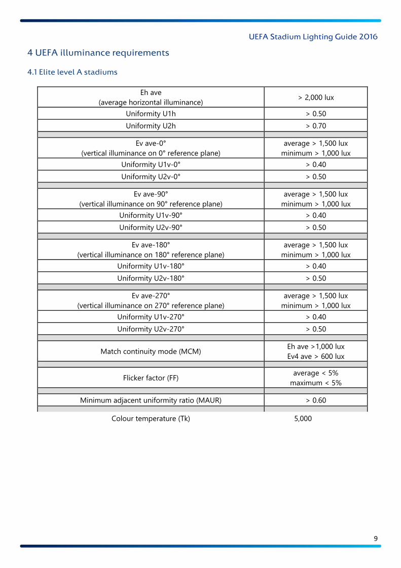
4 UEFA illuminance requirements
4.1 Elite level A stadiums
Eh ave
(average horizontal illuminance) > 2,000 lux
Uniformity U1h > 0.50
Uniformity U2h > 0.70
Ev ave-0°
(vertical illuminance on 0° reference plane)
average > 1,500 lux
minimum > 1,000 lux
Uniformity U1v-0° > 0.40
Uniformity U2v-0° > 0.50
Ev ave-90°
(vertical illuminance on 90° reference plane)
average > 1,500 lux
minimum > 1,000 lux
Uniformity U1v-90° > 0.40
Uniformity U2v-90° > 0.50
Ev ave-180°
(vertical illuminance on 180° reference plane)
average > 1,500 lux
minimum > 1,000 lux
Uniformity U1v-180° > 0.40
Uniformity U2v-180° > 0.50
Ev ave-270°
(vertical illuminance on 270° reference plane)
average > 1,500 lux
minimum > 1,000 lux
Uniformity U1v-270° > 0.40
Uniformity U2v-270° > 0.50
Match continuity mode (MCM) Eh ave >1,000 lux
Ev4 ave > 600 lux
Flicker factor (FF) average < 5%
maximum < 5%
Minimum adjacent uniformity ratio (MAUR) > 0.60
Colour temperature (Tk) 5,000–6,200K
Colour rendering ≥ 80 Ra
Glare rating (GR) < 50
Maintenance factor (MF) 0.85
Power supply Elite level A
UEFA Stadium Lighting Guide 2016
10
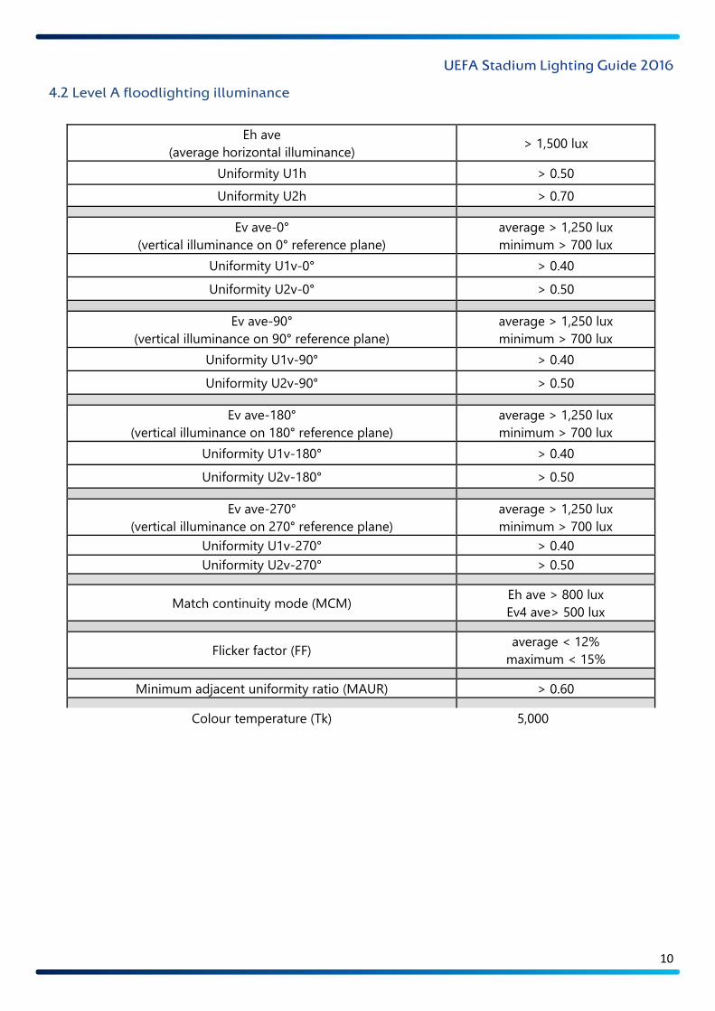
4.2 Level A floodlighting illuminance
Eh ave
(average horizontal illuminance) > 1,500 lux
Uniformity U1h > 0.50
Uniformity U2h > 0.70
Ev ave-0°
(vertical illuminance on 0° reference plane)
average > 1,250 lux
minimum > 700 lux
Uniformity U1v-0° > 0.40
Uniformity U2v-0° > 0.50
Ev ave-90°
(vertical illuminance on 90° reference plane)
average > 1,250 lux
minimum > 700 lux
Uniformity U1v-90° > 0.40
Uniformity U2v-90° > 0.50
Ev ave-180°
(vertical illuminance on 180° reference plane)
average > 1,250 lux
minimum > 700 lux
Uniformity U1v-180° > 0.40
Uniformity U2v-180° > 0.50
Ev ave-270°
(vertical illuminance on 270° reference plane)
average > 1,250 lux
minimum > 700 lux
Uniformity U1v-270° > 0.40
Uniformity U2v-270° > 0.50
Match continuity mode (MCM) Eh ave > 800 lux
Ev4 ave> 500 lux
Flicker factor (FF) average < 12%
maximum < 15%
Minimum adjacent uniformity ratio (MAUR) > 0.60
Colour temperature (Tk) 5,000–6,200K
Colour rendering ≥ 80 Ra
Glare rating (GR) < 50
Maintenance factor (MF) 0.80
Power supply Level A
UEFA Stadium Lighting Guide 2016
11
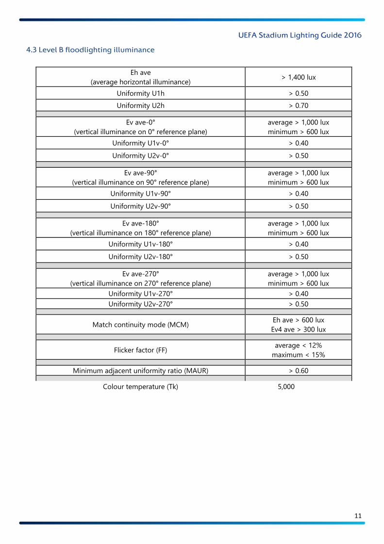
4.3 Level B floodlighting illuminance
Eh ave
(average horizontal illuminance) > 1,400 lux
Uniformity U1h > 0.50
Uniformity U2h > 0.70
Ev ave-0°
(vertical illuminance on 0° reference plane)
average > 1,000 lux
minimum > 600 lux
Uniformity U1v-0° > 0.40
Uniformity U2v-0° > 0.50
Ev ave-90°
(vertical illuminance on 90° reference plane)
average > 1,000 lux
minimum > 600 lux
Uniformity U1v-90° > 0.40
Uniformity U2v-90° > 0.50
Ev ave-180°
(vertical illuminance on 180° reference plane)
average > 1,000 lux
minimum > 600 lux
Uniformity U1v-180° > 0.40
Uniformity U2v-180° > 0.50
Ev ave-270°
(vertical illuminance on 270° reference plane)
average > 1,000 lux
minimum > 600 lux
Uniformity U1v-270° > 0.40
Uniformity U2v-270° > 0.50
Match continuity mode (MCM) Eh ave > 600 lux
Ev4 ave > 300 lux
Flicker factor (FF) average < 12%
maximum < 15%
Minimum adjacent uniformity ratio (MAUR) > 0.60
Colour temperature (Tk) 5,000–6,200K
Colour rendering ≥ 80 Ra
Glare rating (GR) < 50
Maintenance factor (MF) 0.80
Power supply Level B
UEFA Stadium Lighting Guide 2016
12
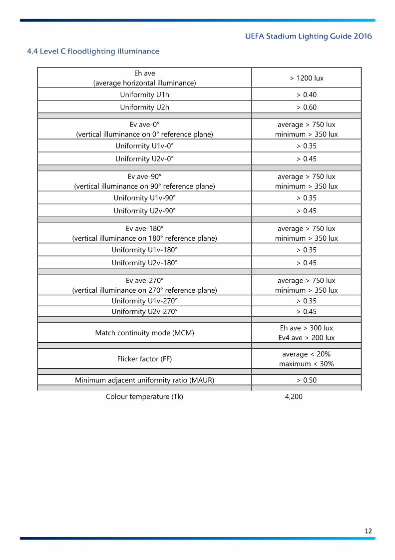
4.4 Level C floodlighting illuminance
Eh ave
(average horizontal illuminance) > 1200 lux
Uniformity U1h > 0.40
Uniformity U2h > 0.60
Ev ave-0°
(vertical illuminance on 0° reference plane)
average > 750 lux
minimum > 350 lux
Uniformity U1v-0° > 0.35
Uniformity U2v-0° > 0.45
Ev ave-90°
(vertical illuminance on 90° reference plane)
average > 750 lux
minimum > 350 lux
Uniformity U1v-90° > 0.35
Uniformity U2v-90° > 0.45
Ev ave-180°
(vertical illuminance on 180° reference plane)
average > 750 lux
minimum > 350 lux
Uniformity U1v-180° > 0.35
Uniformity U2v-180° > 0.45
Ev ave-270°
(vertical illuminance on 270° reference plane)
average > 750 lux
minimum > 350 lux
Uniformity U1v-270° > 0.35
Uniformity U2v-270° > 0.45
Match continuity mode (MCM) Eh ave > 300 lux
Ev4 ave > 200 lux
Flicker factor (FF) average < 20%
maximum < 30%
Minimum adjacent uniformity ratio (MAUR) > 0.50
Colour temperature (Tk) 4,200–6,200K
Colour rendering > 70 Ra
Glare rating (GR) < 50
Maintenance factor (MF) 0.70
Power supply Level C
UEFA Stadium Lighting Guide 2016
13
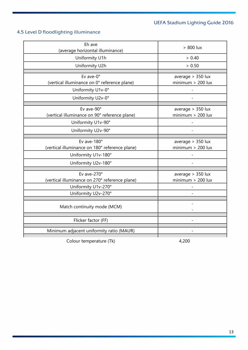
4.5 Level D floodlighting illuminance
Eh ave
(average horizontal illuminance) > 800 lux
Uniformity U1h > 0.40
Uniformity U2h > 0.50
Ev ave-0°
(vertical illuminance on 0° reference plane)
average > 350 lux
minimum > 200 lux
Uniformity U1v-0° -
Uniformity U2v-0° -
Ev ave-90°
(vertical illuminance on 90° reference plane)
average > 350 lux
minimum > 200 lux
Uniformity U1v-90° -
Uniformity U2v-90° -
Ev ave-180°
(vertical illuminance on 180° reference plane)
average > 350 lux
minimum > 200 lux
Uniformity U1v-180° -
Uniformity U2v-180° -
Ev ave-270°
(vertical illuminance on 270° reference plane)
average > 350 lux
minimum > 200 lux
Uniformity U1v-270° -
Uniformity U2v-270° -
Match continuity mode (MCM) -
-
Flicker factor (FF) -
Minimum adjacent uniformity ratio (MAUR) -
Colour temperature (Tk) 4,200–6,200K
Colour rendering > 65 Ra
Glare rating (GR) < 50
Maintenance factor (MF) 0.70
Power supply Level D
UEFA Stadium Lighting Guide 2016
14
5 Illuminance design guidelines
The pitch illuminance system should provide the optimum conditions within the given illuminance level to
ensure that players, officials, spectators and broadcasters are able to perform and enjoy the match without
hindrance.
During the design process, the guidelines below should be used in order to establish a high-quality pitch
illuminance system that satisfies the requirements of the relevant UEFA illuminance level.
5.1 Players and officials
The primary concern should be to give players and officials the optimum conditions in which to perform.
The illuminance system should not distract or hinder players or officials during the match.
5.2 Spectators
The illuminance system should provide spectators with an environment that is comfortable and free from
glare and allows them to see the match clearly.
5.3 Broadcasters and media
Television broadcasters require certain illuminance conditions to enable high-quality pictures to be
produced. The minimum illuminance levels required for specific competitions are specified in Section 4.
5.4 Luminaire mounting positions
The positioning of floodlight luminaires has a huge impact on the pitch illuminance conditions. This is one
of the primary concerns when evaluating the design process. The luminaire mounting positions will have a
direct impact on the pitch illuminance level and uniformity for all planes. The mounting positions will also
have an impact on the creation of player shadows and the visual comfort experienced by players, officials
and spectators.
In recent years, architectural requirements and design aesthetics have challenged the previous illuminance
design guidelines. New stadiums are often designed and constructed in ways which require the pitch
illuminance system to perform to the required standard while also remaining true to the architectural design.
There are now many examples of stadiums in Europe which have pitch illuminance systems that do not
conform to the previous guidelines but do provide good illuminance conditions.
UEFA recommends that all new pitch illuminance designs focus primarily on ensuring that player comfort is
maintained. Design solutions should ensure that the comfort of players, officials and spectators is
maintained, while providing good operating conditions for broadcast television. Any new pitch illuminance
design/concept that achieves this while also fulfilling UEFA’s other pitch illuminance requirements will be
welcomed.
UEFA Stadium Lighting Guide 2016
15
5.5 Floodlight luminaire mounting guide
Ref. Position Guidance
6.1
Corners –
column/tower
floodlight array
To avoid excessive glare around the goal line, particular attention should be
paid to the zone within 15° of either side of the goal line. Multiple luminaires,
as used in column or tower installations, should not be placed in this zone.
6.2 Corners –
linear floodlight array
If the installation design requires luminaires to be positioned within 15° of the
goal line, the luminaires’ focal point should be outside the penalty area.
Luminaires positioned outside the 15° zone may be focused on the penalty
area. This is only suitable for linear floodlight arrays.
6.3
Pitch perimeter –
lateral distance to
luminaire position
An adequate lateral distance between the luminaire mounting positions and
the goal lines and side lines should be maintained in order to achieve the
required vertical illuminance level around the perimeter of the pitch.
6.4
Pitch sides –
luminaire
mounting zone
The luminaires should be mounted at an angle of no less than 25° and no more
than 45° above the centre of the pitch.
6.5 Pitch perimeter –
second linear row
The luminaires should be mounted at an angle of no less than 25° and no more
than 45° above the centre of the pitch. In order to achieve improved vertical
illuminance around the perimeter of the pitch, it may be necessary to install an
additional linear row of luminaires with a greater lateral distance from the pitch.
6.6 Luminaire focus point
angle
In order to avoid discomfort glare being experienced by players and officials,
a general rule during the design process is to ensure that luminaires’ focus
point angle is less than 70° from the line perpendicular to the pitch.
6.7 Pitch sides – luminaire
mounting positions
Stadium structures should not impede the luminous flux of the pitch lighting
system and cause shadows to be cast on the pitch.
6.8
Behind penalty area –
luminaire
mounting zone
To maintain good visual conditions both for attacking players in front of the
goal and for the goalkeeper, luminaires should be mounted more than 60°
from the goal line when in line with the penalty area.
6.9
Behind penalty area –
luminaire
mounting zone
Luminaires positioned behind the goal and parallel to the penalty area should
be mounted greater than 60° from the goal line.
6.10 Behind goal line –
second linear row
An adequate lateral distance between the luminaire mounting position and the
goal lines should be maintained in order to achieve the required vertical
illuminance level around the perimeter of the pitch. In some cases, a second
linear run of luminaires may be installed under a stadium roof canopy to assist
in this area.
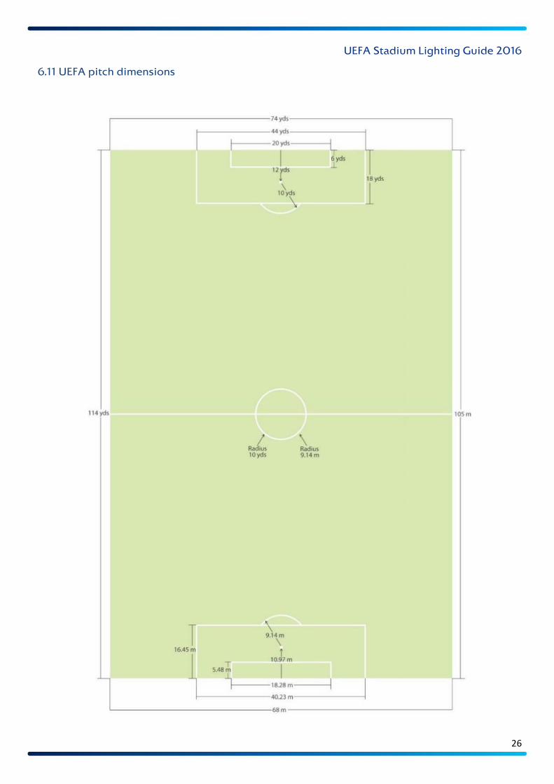
6.11 UEFA pitch
dimensions Official UEFA pitch size and penalty area dimensions
UEFA Stadium Lighting Guide 2016
16
6 Diagrams of design guidelines
6.1 Corners – column/tower floodlight array
When pitch illuminance is provided by means of corner columns or towers with multiple luminaires in a
group (as is generally seen in columns and towers), the luminaires should not be mounted within 15° of
either side of the goal line (see diagram above).
Large multiple arrays of luminaires provide greater levels of discomfort glare and should not, therefore, be
positioned in these areas. A consecutive line of luminaires with more than two rows is considered, for this
purpose, to be a ‘large multiple array’.

UEFA Stadium Lighting Guide 2016
17
6.2 Corners – linear floodlight array
As regards players in the penalty area, the discomfort glare produced by a linear run of luminaires is
considered to be within an acceptable level if the luminaires’ focus points are such that players can stand in
the penalty area and look towards the corners without hindrance.
Luminaires mounted within 15° of the goal line should be focused away from the penalty box, as indicated
in the diagram above.
Multiple arrays of luminaires should not be positioned within 15° of either side of the goal line.
A linear array of luminaires used for this purpose should not comprise more than two rows.

UEFA Stadium Lighting Guide 2016
18
6.3 Pitch perimeter – lateral distance
In order to achieve the required vertical illuminance around the perimeter of the pitch, the luminaires should
have a mounting position with a minimum lateral distance from the pitch perimeter of greater than12m.
UEFA Stadium Lighting Guide 2016
19
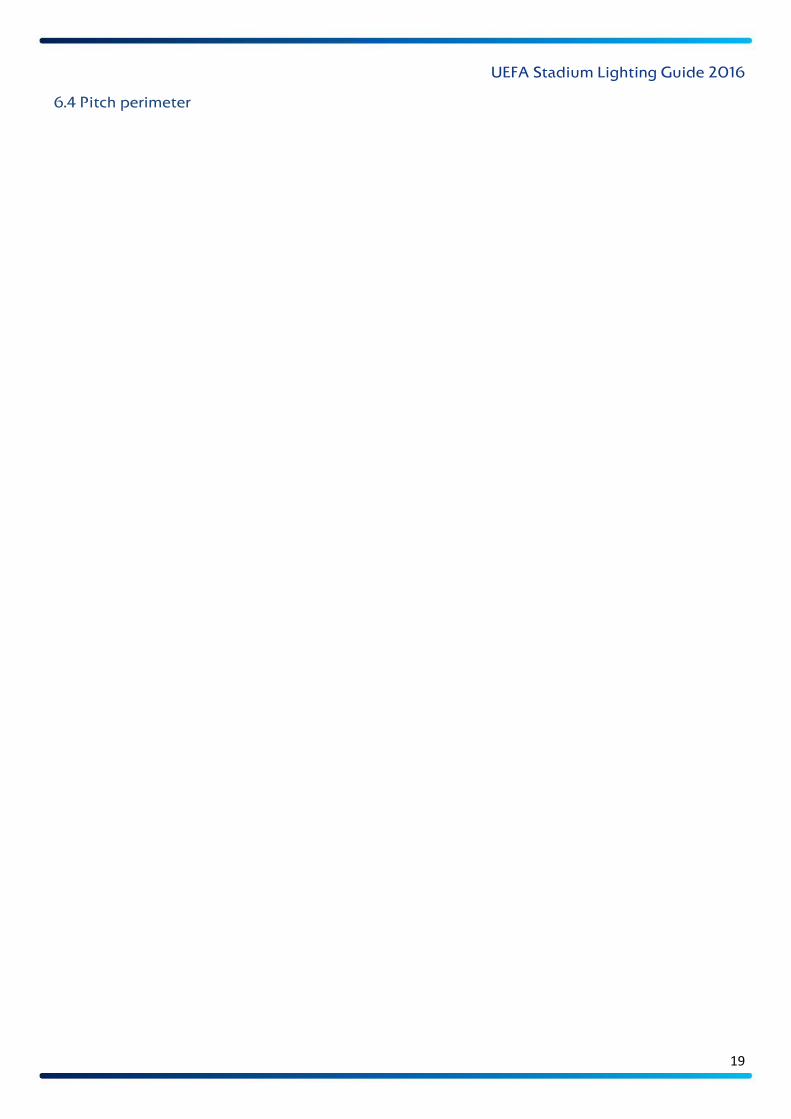
6.4 Pitch perimeter – luminaire mounting zone
The luminaires should not be mounted less than 25° or more than 45° above the centre of the pitch.
This will generally ensure that illuminance conditions comply with UEFA’s guidelines.
If possible, luminaires should be mounted at least 20–25m above the surface of the pitch. If this is not
possible, it is important to develop a design solution that considers the implications of that reduced height
and takes it into account.
One way to ensure that players’ discomfort glare is kept below 50 is to limit the angle of a floodlight’s tilt to
70°, as indicated in the diagram in Section 6.6. However the structural design of some stadiums may make
this impossible. In all glare rating evaluations, evidence should be provided of how the glare rating is kept
below 50.

UEFA Stadium Lighting Guide 2016
20
6.5 Pitch perimeter – second linear row
If the stadium design or existing installation requires luminaires to be positioned within a lateral distance of
12m of the perimeter of the pitch, or if the vertical illuminance requires improvement, a second linear run of
luminaires should be used to achieve the required vertical illuminance around the perimeter of the pitch.

UEFA Stadium Lighting Guide 2016
21
6.6 Luminaires’ focus point angle
In order to avoid discomfort glare being experienced by players and officials, a general rule during the design
process is to ensure that luminaires’ focus point angle is no more than 70° from the line perpendicular to
the pitch, as in the diagram above. This is a good general guideline, but it will not always be possible owing
to the constraints of the stadium’s design.
The above guidance is particularly relevant to point source illuminance systems, as generally seen with high-
intensity discharge lamps. However, it may be necessary to re-evaluate this guidance when using LED
luminaires, which will generally have large arrays of LEDs producing direct point source luminous flux.
UEFA Stadium Lighting Guide 2016
22
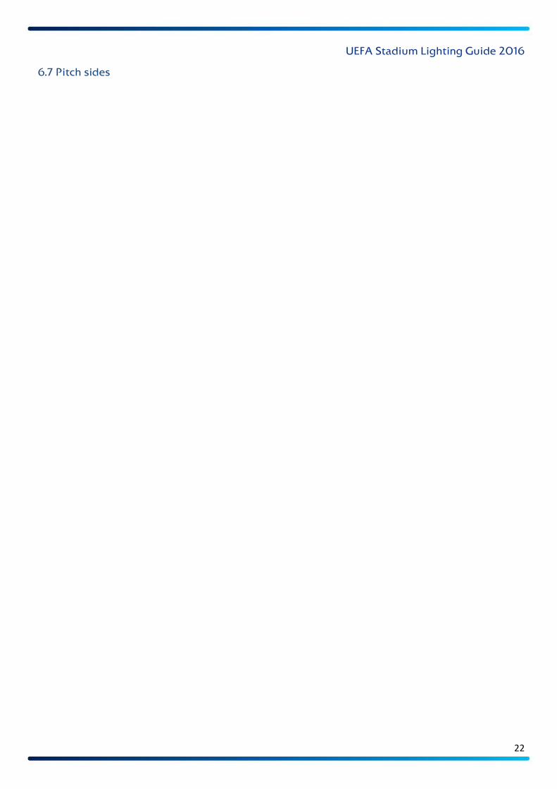
6.7 Pitch sides – luminaire mounting position
Stadium structures should not impede the luminous flux of the pitch lighting system and cause shadows to
be cast on the surface of the pitch. Care should be taken to ensure that the luminous flux projection lines to
the pitch surface are completely clear.

UEFA Stadium Lighting Guide 2016
23
6.8 Behind penalty area – luminaire mounting zone
In order to avoid discomfort glare being experienced by attacking players looking towards the goal,
additional provision is made by increasing the installation angle of luminaires directly behind the penalty
area (as shown in the diagram above).
UEFA Stadium Lighting Guide 2016
24
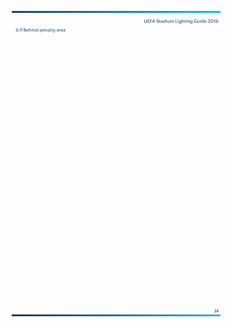
6.9 Behind penalty area – luminaire mounting zone
Luminaires positioned behind the goal and parallel to the penalty box as indicated in Section 6.8 should be
mounted more than 60° from the goal line when in line with the penalty area, as indicated in the diagram
above.
If only a single linear line of luminaires is used, the minimum lateral distance from the goal line should be
12m.
Luminaires that are not in line with the penalty box may be mounted at an angle of more than 45° from the
goal line.

UEFA Stadium Lighting Guide 2016
25
6.10 Behind goal line – second linear row
If the stadium design or existing installation requires luminaires to be positioned within a lateral distance of
12m from the goal line (as indicated by the blue luminaires in the diagram above) or if the vertical illuminance
requires improvement, a second linear run of luminaires should be used to achieve the required vertical
illuminance along the goal line and within the penalty area. Luminaires positioned directly behind the penalty
area should be mounted at an angle of more than 60° (as indicated by the red luminaires in the diagram
above). Outside the area parallel to the penalty area, luminaires may be mounted at an angle of more than
45° (as indicated by the green luminaires).
Where possible, all luminaires behind the goal line should be a minimum of 30m above the pitch surface. If
this is not possible, it is important to develop a design solution that considers the implications of that
reduced height and takes it into account.
UEFA Stadium Lighting Guide 2016
26
6.11 UEFA pitch dimensions
UEFA Stadium Lighting Guide 2016
27
7 Uniformity
A critical element of a pitch illuminance system is the uniformity of illuminance across the whole pitch in all
of UEFA’s reference planes.
The uniformity of illuminance can be defined as how evenly light is distributed over a given reference plane.
The uniformity of illuminance is expressed using two illuminance ratios: U1 and U2.
U1 The total illuminance range, from minimum to maximum, that a person or camera will be exposed to.
The U1 value will contribute to the visual performance experience.
U2 The difference between a person’s normal adapted exposure and the lowest illuminance level on the
given plane. The U2 value will contribute to the visual comfort experience.
Horizontal uniformity of illuminance
U1h A measure of horizontal uniformity of illuminance – the ratio of minimum horizontal illuminance to
maximum horizontal illuminance across all 96 reference points.
U2h A measure of horizontal uniformity of illuminance – the ratio of minimum horizontal illuminance to
average horizontal illuminance across all 96 reference points.
Vertical uniformity of illuminance
U1v-(angle°) A measure of vertical uniformity of illuminance on the specified reference plane – the ratio of
minimum vertical illuminance to maximum vertical illuminance across all 96 reference points.
U2v-(angle°) A measure of vertical uniformity of illuminance on the specified reference plane – the ratio of
minimum vertical illuminance to average vertical illuminance across all 96 reference points.
It should be noted that UEFA’s requirements are the minimum standards for the various illuminance levels.
Experience shows that uniformity values that are calculated during the design process are a good guide, but
are often higher than the values measured after the illuminance system has actually been installed. UEFA
recommends that the illuminance uniformity values that are calculated during the design process are higher
than the minimum requirements to allow for potential declines when real values are measured.
UEFA Stadium Lighting Guide 2016
28
8 Glare
8.1 Glare
Glare is the sensation produced by luminance within the field of vision that is so much stronger than the
eyes are used to that it causes annoyance, discomfort and/or impaired visibility and visual performance.
8.2 Discomfort glare
Discomfort glare is caused by direct glare from luminaires which are too bright, inadequately shielded or too
large in size. It is also caused by reflected glare from specular surfaces lit by other sources (which in a stadium
may be the sun).
When the eye has got used to the dark, it is particularly susceptible to the impairment and depression of
central vision when a bright light enters the field of vision.
8.3 Evaluation of glare
The method of determining the glare effect of a light source or a group of light sources is complicated. Glare
will certainly increase as the number of light (or glare) sources increases and the size of the light (or glare)
source increases. The size, luminance and position of light sources will all affect the level of glare that is
experienced.
Glare is a subjective factor, for which a practical evaluation system has been devised for outdoor sports
applications by the International Commission on Illumination (CIE) on the basis of extensive field tests. The
CIE 112-1994 Glare Evaluation System for Use within Outdoor and Area Lighting –
http://div5.cie.co.at/?i_ca_id=599&pubid=166 - defines a glare rating (GR) with an assessment scale of 10 to
90. The lower the glare rating, the better the glare situation.
The validity of this system is restricted to viewing directions below eye level, and it is mainly used for
predicting the degree of glare. During the lighting design phase, a glare assessment based on CIE 112-1994
should be carried out. Calculations should be made for observer positions using the grid points on page 58.
Assessments should be made every 15°, starting from 0° or 180°, over a total of 360°. Observer positions
should be 1.75m above the pitch surface.
The maximum glare rating and the corresponding direction should be displayed for each observer position.
UEFA Stadium Lighting Guide 2016
29
9 Pitch illuminance switch mode (PISM)
The pitch illuminance system should be pre-programmed with various different modes. The number of
modes may vary from stadium to stadium. The list below provides a few examples:
Mode 1: Full match mode (FMM)
Mode 2: Match continuity mode (MCM)
Mode 3: Training mode (TM)
Mode 4: Maintenance mode (MM)
9.1 Full match mode
This involves the pitch illuminance system operating in a manner that satisfies the requirements specified for
the relevant UEFA illuminance level.
9.2 Match continuity mode
This mode should automatically be activated when the primary power supply fails. The pitch illuminance
system should switch to the MCM and perform in accordance with (or above) the minimum standards
specified for the relevant UEFA level.
In terms of the uniformity of illuminance, U1 must be greater than 0.5 on the horizontal plane and 0.4 on the
vertical plane. It is not considered necessary to evaluate U2 for the MCM.
The MCM is essential and should be part of the design process. In order for this mode to operate successfully,
the power supply facilities and options available must be carefully considered during the design process.
9.3 Training mode
This involves the pitch illuminance system operating with an average horizontal illuminance of 500 lux.
9.4 Maintenance mode
This involves the pitch illuminance system operating with an average horizontal illuminance of 250 lux.
UEFA Stadium Lighting Guide 2016
30
10 Flicker factor (FF)
10.1 Flicker factor guidance
During broadcasts, we can often see that some illuminance systems cause the picture to flicker during slow-
motion replays. The flicker is distracting and impairs the viewer’s experience, so it should be eliminated where
possible. The circumstances that produce the flicker will vary depending on the modulation of the flicker, the
alternating voltage frequency and the camera frame rate.
The term ‘flicker factor’ refers to the amount of modulation of luminance on a given plane during a complete
cycle. It denotes the relationship between the maximum luminance value and the minimum luminance value
over a full cycle and is expressed as a percentage.
Flicker: A rapid and repeated change in the brightness of light over time.
Modulation: A measure of light variation during periodic oscillations.
The flicker factor is calculated using the following formula:
FF = 1/2 x Emax - Emin x 100%
E average
or
FF = Emax - Emin x 100%
Emax + Emin
Where:
E represents the illuminance level during a complete cycle.
In all but the most extreme circumstances, it is possible to eliminate the flicker that is seen during slow-
motion replays. The table on the next page provides a general indication of the flicker factor values produced
by various illuminance systems.
A flicker factor of less than 5% will not generally cause problems for slow-motion replays of up to 300 frames
per second. While the number of frames per second will vary depending on the technology used, an
illuminance system with a flicker factor of less than 5% will eliminate perceived flicker for most technology
used within the sports television industry.
UEFA Stadium Lighting Guide 2016
31
Illuminance flicker is commonly eliminated by installing electronic control ballasts or square wave form
ballasts in the illuminance system. This technology can generally be added to existing installations, as well
as being available for new installations.
The flicker that is observed with very high numbers of frames per second can also be eliminated using
computer processing. However, this method has other limitations.
The level of flicker that is considered acceptable is indicated in the tables in Section 4.
10.2 Flicker factor reference table
10.3 Flicker factor with three-phase power supply
Pitch illuminance systems that use standard-frequency ballasts with typical sine wave luminance modulation
characteristics will produce a wide range of flicker factor test results. This is due to the variation at test points
in the overlapping of luminous flux from different luminaires at different angles. With careful planning, it
may be possible to design the luminaire focus points for all areas and planes of the pitch to receive
overlapping luminous flux from luminaires at different angles. This may produce substantial improvements
and may meet UEFA’s requirements for level B and level C stadiums.
Although the above method may produce substantial improvements, it will not meet the requirements for
level A Elite stadiums without additional solutions to reduce the modulation of luminance. A mixture of
electronic or square wave ballasts with standard-frequency sine wave ballasts may produce a flicker factor
below 5%. This system will be more successful in larger installations where a greater number of luminaires
are available to provide overlapping luminous flux coming from different angles.
Type of
illuminance system
FF value (guide only)
Natural daylight
0%
LED luminaires
(flicker dependent on the type of LED power
supply used)
< 3%
Discharge lamps
with 100% electronic ballasts
< 4%
Discharge lamps with
magnetic ballasts spread uniformly across
three-phase power supply
8–20%
Discharge lamps with
magnetic ballasts on single-phase
power supply
30–50%
UEFA Stadium Lighting Guide 2016
32
A pitch illuminance system that involves overlapping luminous flux coming from different angles should use
a greater number of flicker factor test points to ensure that the flicker factor values are consistent in all areas.
It is recommended that 24 test points are used.
Measures used to reduce the flicker factor should not impinge upon the uniformity of illuminance on any
plane.
10.4 Flicker factor testing
It is possible to measure the flicker factor at a specific stadium to provide a precise evaluation. The
assessment should be carried out by a competent technician with a suitable meter. That meter should be
recalibrated on an annual basis.
The flicker factor test should be conducted as indicated.
10.5 12-point flicker factor test
At each of the six positions indicated in Section 10.8, a vertical flicker factor reading should be taken at a
height of 1m on the 90° and 270° planes.
The 12-point average is calculated by dividing the sum of those 12 values by 12.
The maximum flicker factor value is the highest measured value of the 12 points.
The maximum permitted flicker factor is listed below for each UEFA level.
UEFA Stadium Lighting Guide 2016
33
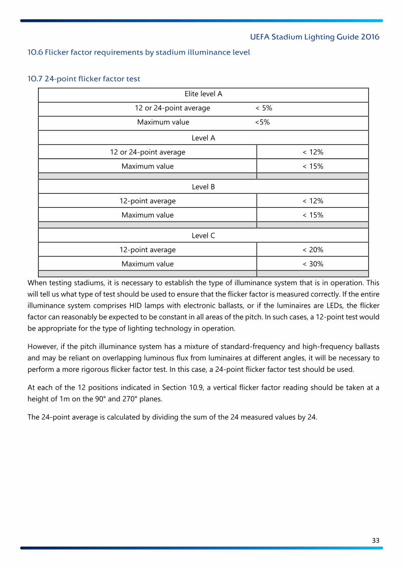
10.6 Flicker factor requirements by stadium illuminance level
10.7 24-point flicker factor test
When testing stadiums, it is necessary to establish the type of illuminance system that is in operation. This
will tell us what type of test should be used to ensure that the flicker factor is measured correctly. If the entire
illuminance system comprises HID lamps with electronic ballasts, or if the luminaires are LEDs, the flicker
factor can reasonably be expected to be constant in all areas of the pitch. In such cases, a 12-point test would
be appropriate for the type of lighting technology in operation.
However, if the pitch illuminance system has a mixture of standard-frequency and high-frequency ballasts
and may be reliant on overlapping luminous flux from luminaires at different angles, it will be necessary to
perform a more rigorous flicker factor test. In this case, a 24-point flicker factor test should be used.
At each of the 12 positions indicated in Section 10.9, a vertical flicker factor reading should be taken at a
height of 1m on the 90° and 270° planes.
The 24-point average is calculated by dividing the sum of the 24 measured values by 24.
Elite level A
12 or 24-point average < 5%
Maximum value <5%
Level A
12 or 24-point average < 12%
Maximum value < 15%
Level B
12-point average < 12%
Maximum value < 15%
Level C
12-point average < 20%
Maximum value < 30%

UEFA Stadium Lighting Guide 2016
34
10.8 Flicker factor test reference points – 12-point high-frequency test
The maximum flicker factor value is the highest measured single value at any given test points.
UEFA Stadium Lighting Guide 2016
35
10.9 Flicker factor test reference points – 24-point test
UEFA Stadium Lighting Guide 2016
36
11 Minimum adjacent uniformity ratio (MAUR)
Any rapid change in the illuminance level on a given plane will cause camera exposure inconsistencies. During
a fast-moving football match, it is unrealistic to expect the camera settings to be changed successfully on a
consistent basis when the camera and the subject are both moving rapidly. The MAUR is used to ensure
greater consistency in terms of camera exposure and thus greater freedom for the camera operator to
provide dynamic pictures. The difference between the illuminance values of any two adjacent points on any
given plane in any direction should be no greater than the permitted level stipulated in the tables in Section
4. That requirement takes the form of a minimum permissible ratio between the two points.
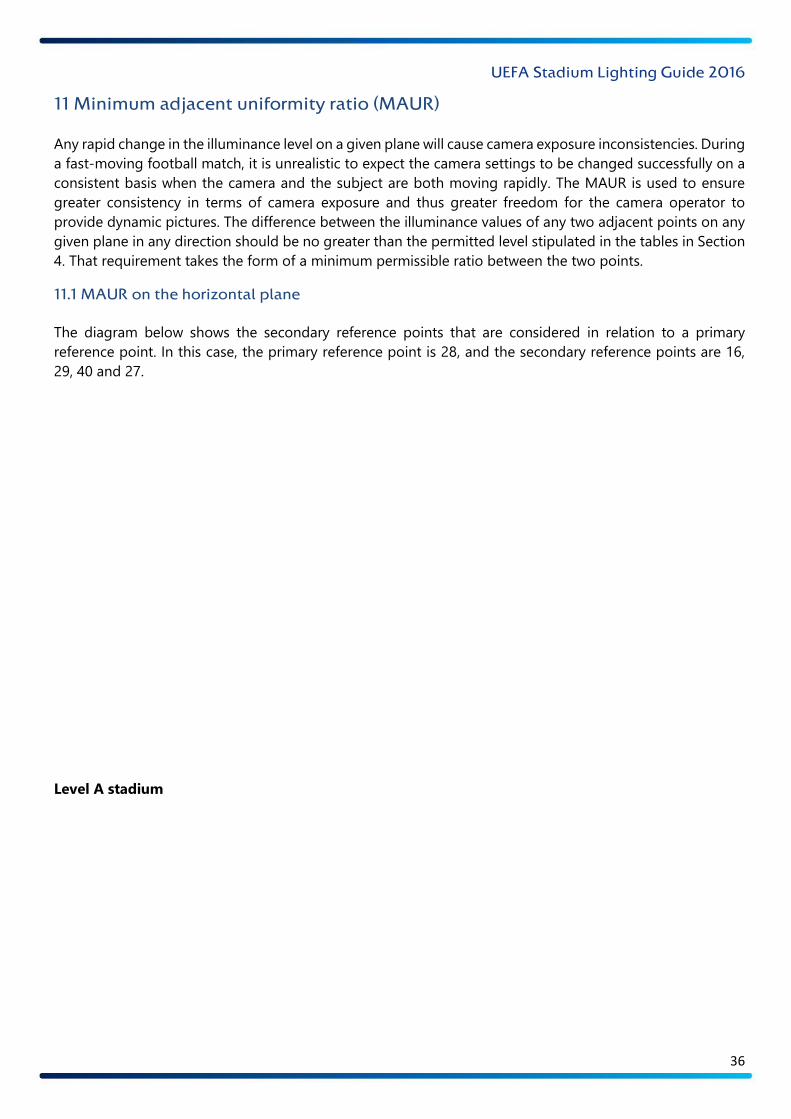
11.1 MAUR on the horizontal plane
The diagram below shows the secondary reference points that are considered in relation to a primary
reference point. In this case, the primary reference point is 28, and the secondary reference points are 16,
29, 40 and 27.
Level A stadium – MAUR evaluation
Reference point 28 on horizontal plane
Reference point 28 – Eh = 2,325 lux
MAUR > 0.60
The illuminance value at the secondary reference points 16, 29, 40 and 27 on the horizontal plane must be
greater than 2,325 x 0.60 = 1,395 lux.
UEFA Stadium Lighting Guide 2016
37
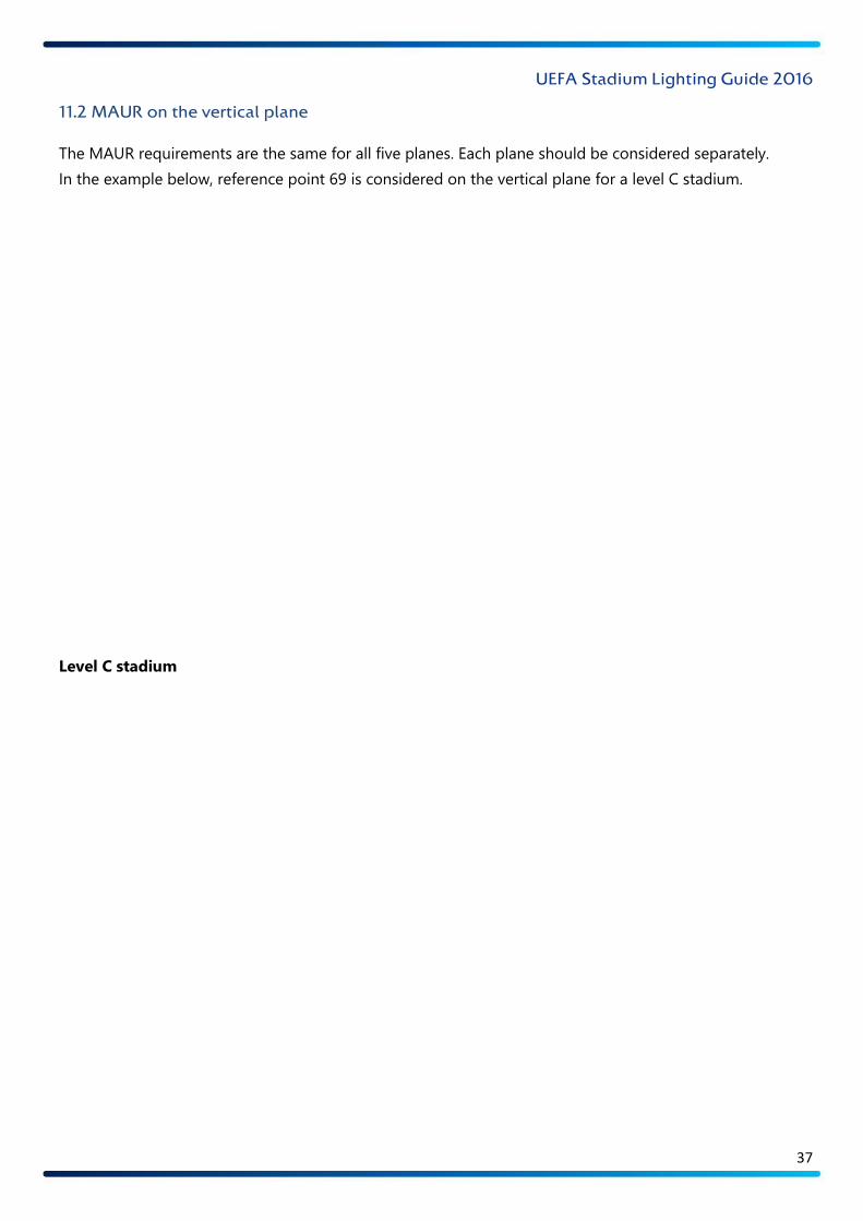
11.2 MAUR on the vertical plane
The MAUR requirements are the same for all five planes. Each plane should be considered separately.
In the example below, reference point 69 is considered on the vertical plane for a level C stadium.
Level C stadium – MAUR evaluation
Reference point 69 on the 270° vertical plane
Reference point 69 – Ev-270° = 1,548 lux
MAUR > 0.50
The illuminance value at the secondary reference points 57, 70, 81 and 68 on the 270° vertical plane must be
greater than 1,548 x 0.50 = 774 lux.
UEFA Stadium Lighting Guide 2016
38
12 Colour temperature
‘Colour temperature’ describes the feeling or appearance of how warm (red) or cool (blue) a certain type of
illumination appears to be. It is measured in kelvins (K).
Digital camera technology allows video-produced media to be altered to ‘gain’ colour and contrast, as
required to produce the desired colour quality. The required colour temperature range varies depending on
the stadium illuminance level, with the minimum and maximum levels across all levels being 4,200K and
6,200K respectively.
It is often necessary to start the broadcasting of a football match in daylight and finish with all the pitch
illuminance provided by the floodlighting system. On these occasions, the artificial lighting should generally
be used at the beginning of the broadcast to allow a gradual change from daylight to artificial illuminance.
During this period, the broadcast engineers will be able to make minor adjustments to the camera settings
as required.
The diagram below provides a guide to the colour temperature range required for UEFA stadiums.
12.1 Colour temperature guide
UEFA Stadium Lighting Guide 2016
39
13 Colour rendering
Colour rendering, which is expressed as a score between 0 and 100 Ra on the Colour Rendering Index (CRI),
describes how a light source makes the colour of an object appear to human eyes and how well subtle
variations in colour shades are revealed. The higher the CRI rating, the better the colour rendering.
UEFA’s requirements stipulate that for good colour production by the artificial illumination system, the CRI
rating needs to be ≥ 80 for level A and level B stadiums, ≥ 70 for level C stadiums and ≥ 65 for level D
stadiums.
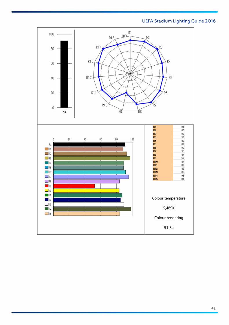
The following diagram provides test information of chromaticity values and should be used as a guide to
what is required for all new and old UEFA stadiums:
UEFA Stadium Lighting Guide 2016
40
Chromaticity values of lamp performance
UEFA Stadium Lighting Guide 2016
41
Colour temperature
5,489K
Colour rendering
91 Ra
UEFA Stadium Lighting Guide 2016
42
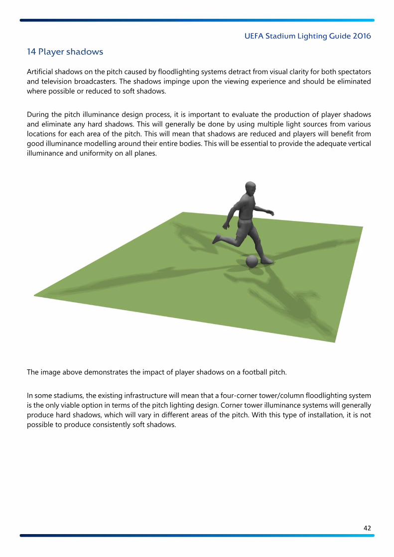
14 Player shadows
Artificial shadows on the pitch caused by floodlighting systems detract from visual clarity for both spectators
and television broadcasters. The shadows impinge upon the viewing experience and should be eliminated
where possible or reduced to soft shadows.
During the pitch illuminance design process, it is important to evaluate the production of player shadows
and eliminate any hard shadows. This will generally be done by using multiple light sources from various
locations for each area of the pitch. This will mean that shadows are reduced and players will benefit from
good illuminance modelling around their entire bodies. This will be essential to provide the adequate vertical
illuminance and uniformity on all planes.
The image above demonstrates the impact of player shadows on a football pitch.
In some stadiums, the existing infrastructure will mean that a four-corner tower/column floodlighting system
is the only viable option in terms of the pitch lighting design. Corner tower illuminance systems will generally
produce hard shadows, which will vary in different areas of the pitch. With this type of installation, it is not
possible to produce consistently soft shadows.
UEFA Stadium Lighting Guide 2016
43
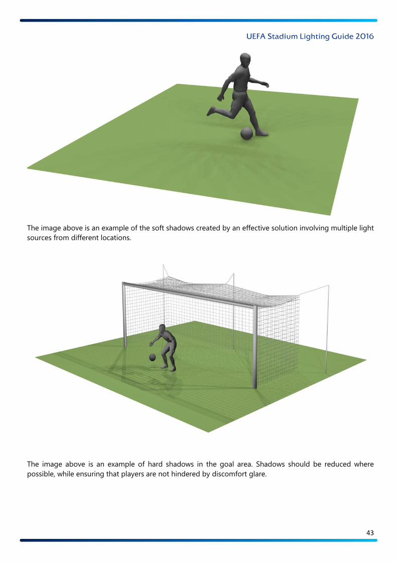
The image above is an example of the soft shadows created by an effective solution involving multiple light
sources from different locations.
The image above is an example of hard shadows in the goal area. Shadows should be reduced where
possible, while ensuring that players are not hindered by discomfort glare.
UEFA Stadium Lighting Guide 2016
44
15 Maintenance factor
The average illuminance values required by the tables in Section 4 should be achieved during matches.
However, a maintenance factor is used to take account the depreciation of luminous flux caused by the
ageing and soiling of the light sources, reflectors and front glasses. In the absence of any other information,
the maintenance factor indicated in the relevant table in Section 4 should be used.
However, it is possible to modify that maintenance factor if relevant information is available and systems are
in place that facilitate a calculated alteration to that value for a given project.
Reasons to alter the maintenance factor are provided below:
– A proactive and frequent maintenance programme. This would require the implementation of a
comprehensive and documented schedule of lamp replacement, luminaire cleaning, voltage
regulation and illuminance testing. Most stadium pitch illuminance systems would not be suitable
for this kind of very proactive maintenance.
– Luminaires that use LED technology. The rate of lumen depreciation is very low with this
technology. In order to alter the maintenance factor, a documented schedule of work including
luminaire cleaning, voltage regulation and illuminance testing should be implemented. It is not
recommended to increase the maintenance factor beyond a value of 0.90 when using LED
luminaires in normal circumstances.
– Lumen depreciation may be compensated for by the use of ‘constant illumination lamp
technology’. This system would need to be available and supported by the luminaire manufacturer,
with documented analysis of the pitch illuminance system’s performance with voltage regulation.
It would also be necessary to provide a schedule of lamp replacement, luminaire cleaning, voltage
regulation and illuminance testing.
– If the stadium environment is subject to harsh weather conditions or airborne dirt that could affect
the long-term performance of the luminaires, it will be necessary to lower the maintenance factor
to an appropriate level. In such circumstances, a study should be carried out to evaluate the
conditions. A typical maintenance factor in the above circumstances might be 0.70 or 0.75.
UEFA Stadium Lighting Guide 2016
45
16 Power supply
It is essential that the power supply for the pitch illuminance system is reliable to ensure that matches and
television broadcasts can continue without disruption. A suitable alternative back-up power supply is
required in case the primary source fails in some way. A power supply evaluation is required by UEFA for all
existing stadiums. For newly built stadiums, it is recommended that the power supply system is designed to
meet the requirements stipulated for the relevant UEFA illuminance level.
The following points apply to all levels:
i The primary power source is the main power source for the pitch illuminance system –
generally the national grid.
ii The secondary power source is the alternative power source used as a back-up supply in case
the main power source fails – generally an on-site generator.
iii The two power supplies should be completely independent of each other, with one system
not reliant on the other to operate.
iv In the event of disruption to the primary power supply, the secondary power supply should
be engaged automatically, with no disruption to the pitch illuminance system or other stadium
facilities.
v The disruption caused by lighting systems switching to a different power supply will vary
depending on the duration of the power disruption and the type of floodlight luminaire. If the
primary power supply is disconnected and the secondary power supply is engaged with immediate
effect, it may take up to 10–15 minutes before a discharge lighting system is fully operational. This
is due to the time required for lamps to cool down before re-striking and then running up to full
colour temperature. To ensure pitch illuminance continues without disruption, a UPS system is
often used in the pitch illuminance power system.
vi If the primary power source fails, the secondary power source must be fully operational within
the specified period of time.
vii After the initial power failure, the pitch illuminance system must operate at the illuminance
level stipulated for the relevant level.
viii After the initial power failure, the illuminance system must be operational at the required level
within 12 minutes.
ix Once the pitch illuminance system is being powered by the secondary power supply, it is
necessary to ensure that the primary power supply can only be re-engaged manually. This will
ensure that any further disruption is minimised and controlled.
UEFA Stadium Lighting Guide 2016
46
The specific power supply requirements for each UEFA illuminance level are listed in the tables on the
following pages.
16.1 UEFA power supply requirements – elite level A
i Primary power source
Meets 100% of
requirements
at 100% duty cycle
ii Secondary power source
Meets 100% of
requirements
at 100% duty cycle
iii Primary power supply completely independent from
secondary power supply? Yes
iv Automatic switching between the two power supplies in
the event that one power source fails? Yes
v
Disruption to the pitch illuminance system caused by
failure of the primary power source before the match
continuity illuminance conditions are operational
No disruption permitted
vi
Uninterrupted illuminance conditions (as specified in
point vii) without disruption after the primary power
supply fails?
Yes
vii Illuminance conditions maintained after the primary
power supply fails
Minimum of Eh 1,000 lux
Minimum of Ev4 600 lux
viii Illuminance conditions re-established within 12 minutes
100% of normal match
illuminance conditions
required
ix Manually controlled operation to re-engage primary
power supply after power disruption? Yes

UEFA Stadium Lighting Guide 2016
47
16.2 UEFA power supply requirements – level A
i Primary power source
Meets 100% of
requirements
at 100% duty cycle
ii Secondary power source
Meets 100% of
requirements
at 100% duty cycle
iii Primary power supply completely independent from
secondary power supply? Yes
iv Automatic switching between the two power supplies in
the event that one power source fails? Yes
v
Disruption to the pitch illuminance system caused by
failure of the primary power source before the match
continuity illuminance conditions are operational
No disruption permitted
vi
Uninterrupted illuminance conditions (as specified in
point vii) without disruption after the primary power
supply fails?
Yes
vii Illuminance conditions maintained after the primary
power supply fails
Minimum of Eh 800 lux
Minimum of Ev4 500 lux
viii Illuminance conditions re-established within 12 minutes
100% of normal match
illuminance conditions
required
ix Manually controlled operation to re-engage primary
power supply after power disruption? Yes

UEFA Stadium Lighting Guide 2016
48
16.3 UEFA power supply requirements – level B
i Primary power source
Meets 100% of
requirements
at 100% duty cycle
ii Secondary power source
Meets > 70% of
requirements
at 100% duty cycle
iii Primary power supply completely independent from
secondary power supply? Yes
iv Automatic switching between the two power supplies in
the event that one power source fails?
Yes – or effective and
approved manual
procedure
v
Disruption time caused by failure of the primary power
source before the secondary power supply is fully
operational
Three minutes permitted
vi
Uninterrupted illuminance conditions (as specified in
point vii) without disruption after the primary power
supply fails?
No
vii Illuminance conditions re-established within three
minutes
Minimum of Eh 400 lux
Minimum of Ev4 300 lux
viii Illuminance conditions re-established within 12 minutes
Minimum of 70% of
normal match illuminance
conditions
ix Manually controlled operation to re-engage primary
power supply after power disruption? Yes
UEFA Stadium Lighting Guide 2016
49
16.4 UEFA power supply requirements – level C
i Primary power source
Meets 100% of
requirements
at 100% duty cycle
ii Secondary power source
Meets > 50% of
requirements
at 100% duty cycle
iii Primary power supply completely independent from
secondary power supply? Yes
iv Automatic switching between the two power supplies in
the event that one power source fails?
Yes – or effective and
approved manual
procedure
v
Disruption time caused by failure of the primary power
source before the secondary power supply is fully
operational
15 minutes permitted
vi
Uninterrupted illuminance conditions (as specified in
point vii) without disruption after the primary power
supply fails?
No
vii Illuminance conditions re-established within three
minutes Minimum of Eh 350 lux
viii Illuminance conditions re-established within 12 minutes
Minimum of 50% of
normal match illuminance
conditions
ix Manually controlled operation to re-engage primary
power supply after power disruption? Yes

UEFA Stadium Lighting Guide 2016
50
16.5 UEFA power supply requirements – level D
i Primary power source
Meets 100% of
requirements
at 100% duty cycle
ii Secondary power source
-
iii Primary power supply completely independent from
secondary power supply? -
iv Automatic switching between the two power supplies in
the event that one power source fails? -
v
Disruption time caused by failure of the primary power
source before the secondary power supply is fully
operational
-
vi
Uninterrupted illuminance conditions (as specified in
point vii) without disruption after the primary power
supply fails?
-
vii Illuminance conditions re-established within three
minutes
-
viii Illuminance conditions re-established within 12 minutes
-
ix Manually controlled operation to re-engage primary
power supply after power disruption? -
UEFA Stadium Lighting Guide 2016
51
17 LED pitch perimeter display systems
Pitch perimeter display systems provide an opportunity to tailor advertising and stadium management
information to each individual event.
UEFA’s LED pitch perimeter board guidelines should be consulted prior to broadcasts. The LED advertising
system should be assessed on installation and tested prior to each broadcast event. The LED display panel
should operate within UEFA guidelines so as not to affect the camera balance or exposure during the match
coverage.
The basic minimum technical specifications are listed below and will be valid until 2018:
LED configuration: 3-in-1 SMD
Screen height: Minimum of 90cm; maximum of 100cm
(maximum height more for existing systems to avoid losing seats)
Total length: Minimum length of 246m; ideal length of 257m
Pixel pitch: Ideal minimum quality level: 12.5mm x 12.5mm (real)
(pitch can be symmetrical or asymmetrical)
Horizontal viewing angle: Minimum of 140°
Refresh rate: Minimum of 2,800Hz
Luminance: Minimum of 5,500Nit
Data feeds: Control signal connection via two redundant feed points;
data ring loop configured
For further information, consult the latest version of the guidelines or contact UEFA.
UEFA Stadium Lighting Guide 2016
52
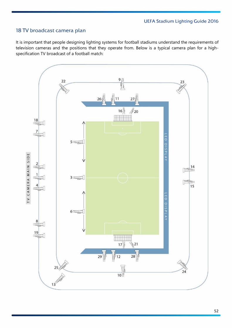
18 TV broadcast camera plan
It is important that people designing lighting systems for football stadiums understand the requirements of
television cameras and the positions that they operate from. Below is a typical camera plan for a high-
specification TV broadcast of a football match:
UEFA Stadium Lighting Guide 2016
53
18.1 Key to camera plan
That camera plan is fairly typical, but some broadcasters and TV directors will deviate from it slightly. The
purpose of the plan is to help you understand how the different elements of the lighting design should be
used to ensure the correct illuminance conditions in all areas of the pitch.
Key to camera plan:
1 MAIN CAMERA
2 CLOSE-UP CAMERA
3 PITCHSIDE HALFWAY CAMERA
4 CLOSE-UP CAMERA
5-6 STEADICAMS
7-8 22-YARD CAMERAS
9-10 HIGH-BEHIND-GOAL CAMERAS
11-12 LOW-BEHIND-GOAL CAMERAS
13 BEAUTY SHOT CAMERA
14-15 REVERSE ANGLE CAMERAS
16-17 MINI-CAMERAS
18-19 GOAL LINE CAMERAS
20-21 HOT HEAD CAMERAS
22-25 CORNER CAMERAS
26-29 HI-MOTION OR BIG LENS CLOSE-UP CAMERAS
The camera plan above does not show the cameras used for presentation/interview and analysis purposes,
which are not relevant for this document.
UEFA Stadium Lighting Guide 2016
54
19 Environmental guidance
There are a number of bodies that provide certification for buildings which are designed and constructed in
line with strict sustainability guidelines. The most prominent of these bodies are BREEAM (in Europe) and
LEED (in the US). Both of these bodies provide an extensive list of parameters and checklists which need to
be followed and implemented, after which the designated certification body assesses the level of compliance
and issues the appropriate certification for the building. Both UEFA and FIFA recommend that all modern
stadiums adhere to the standards stipulated by one of these two certification bodies. However, it is ultimately
down to the stadium developers themselves to (i) be fully aware and supportive of the need for an
environmentally responsible approach, (ii) proactively include sustainability initiatives within the project brief
and (iii) direct the design consultants accordingly.
19.1 Environmental impact of illuminance
Many countries will have regulations and guidelines aimed at ensuring that the quantity of stray illuminance
does not have an undue impact on the local community.
The type of stadium structure and pitch illuminance system will determine the level of illuminance that is
produced in areas outside the stadium. A report should be produced with adequate reference points in areas
around the stadium showing the illuminance levels created by the pitch illuminance system on the horizontal
and vertical planes. The report should comply with the guidelines produced by the relevant authorities and
be submitted for their approval.
For reference purposes, pitch illuminance systems should not produce illuminance levels greater than 50 lux
on the vertical plane at a height of 1.5m and a distance of 50–200m from the stadium perimeter. For lower-
illuminance level stadiums the stray light produced by the pitch illuminance system should be lower.
19.2 Environmental impact of glare
The pitch illuminance system should be designed in such a way that it does not produce levels of disability
glare or discomfort glare that could cause disturbance to people within the local community. Particular
attention should be devoted to ensuring that no drivers of vehicles on adjacent roads are affected by the
pitch illuminance system.
UEFA Stadium Lighting Guide 2016
55
20 UEFA Pitch Illuminance Test Report introduction
UEFA uses illuminance test reports to assess the illuminance conditions at venues. Tests should only be
carried out by qualified personnel using the correct equipment. Equipment must have been recalibrated
within the last 12 months.
The UEFA Pitch Illuminance Test Report can be found across pages 55-62 of these guidelines.
UEFA Stadium Lighting Guide 2016
56
UEFA Pitch Illuminance Test Report
UEFA requires that all venues which could potentially host a televised match undergo assessments of their
pitch illuminance systems.
Such illuminance tests must be conducted in accordance with UEFA’s guidelines to ensure a consistent and
objective analysis of the illuminance conditions at all relevant stadiums.
The illuminance test procedure and requirements are detailed below.
Inspection equipment
The illuminance meter used for the illuminance test should be suitable for a floodlighting environment, with
a wide angle receptive light sensor. The meter must be recalibrated on an annual basis.
Test procedure
A football pitch measures 68m by 105m. This area is divided up into a grid containing 96 points. At each
point, an illuminance test is carried out to measure both the horizontal illuminance and the vertical
illuminance at four different angles. Thus, the test will require 480 illuminance tests in total. Please ensure
that the correct orientation is used when marking out the grid positions. The orientation can be seen in the
pitch orientation plan.
Care should be taken when recording illuminance readings. The illuminance meter should always be
positioned at the correct angle for the intended measurement. Personnel carrying out the test must not
create any shadows that could impinge upon the illuminance meter. The meter should be 1m above the
playing surface.
The illuminance reading for each grid point should be recorded on the relevant illuminance grid plan.
Horizontal test: The meter is positioned facing upwards, 1m above the playing surface, and parallel to the
pitch, at every grid point.
Vertical test: The meter is positioned perpendicular to the pitch, 1m above the playing surface, at every grid
point. The meter should then be adjusted for each of the four test positions. The test positions are indicated
on the vertical illuminance grid plan and are at 0°, 90°, 180° and 270°. This procedure should be repeated at
all 96 grid points.
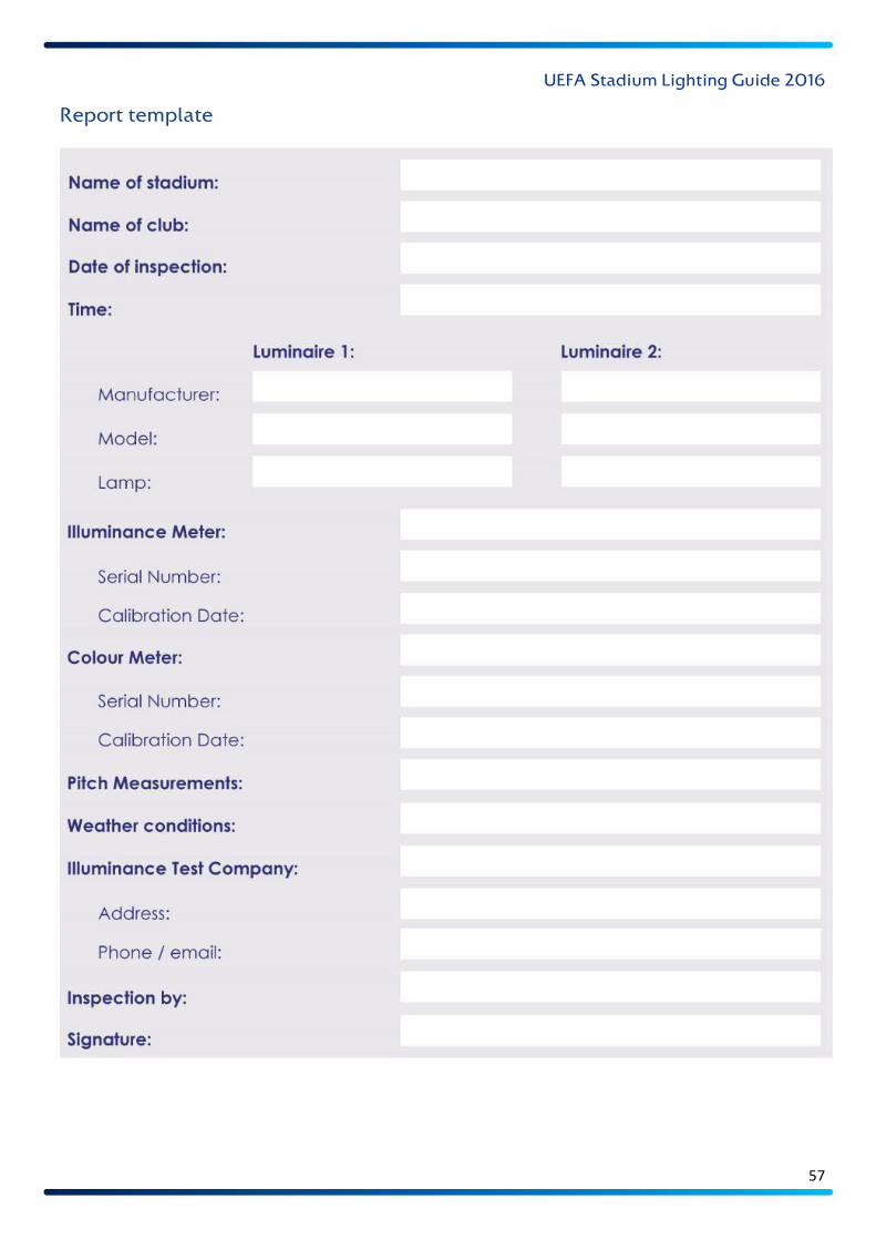
UEFA Stadium Lighting Guide 2016
57
Report template
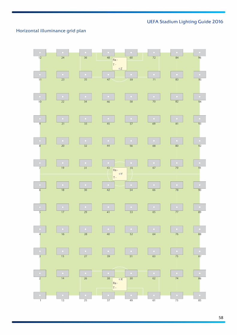
UEFA Stadium Lighting Guide 2016
58
Horizontal illuminance grid plan
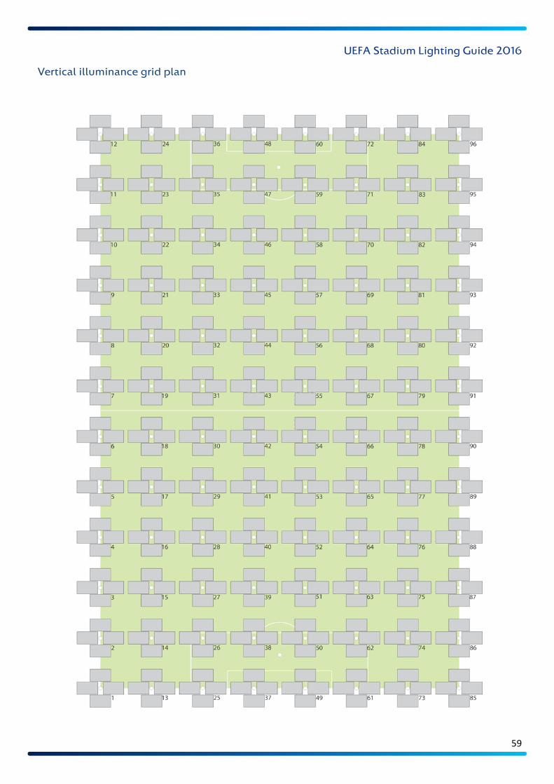
UEFA Stadium Lighting Guide 2016
59
Vertical illuminance grid plan

UEFA Stadium Lighting Guide 2016
60
Illuminance test – pitch orientation plan
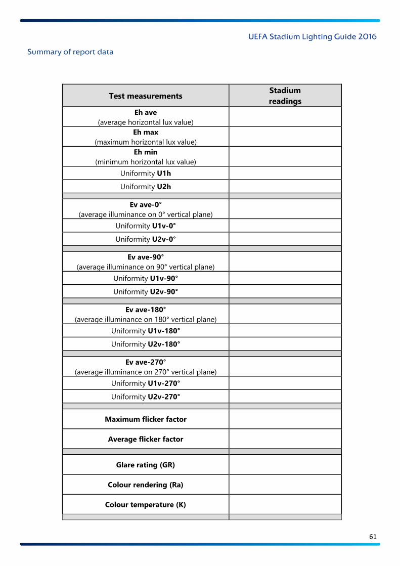
UEFA Stadium Lighting Guide 2016
61
Summary of report data
Test measurements Stadium
readings
Eh ave
(average horizontal lux value)
Eh max
(maximum horizontal lux value)
Eh min
(minimum horizontal lux value)
Uniformity U1h
Uniformity U2h
Ev ave-0°
(average illuminance on 0° vertical plane)
Uniformity U1v-0°
Uniformity U2v-0°
Ev ave-90°
(average illuminance on 90° vertical plane)
Uniformity U1v-90°
Uniformity U2v-90°
Ev ave-180°
(average illuminance on 180° vertical plane)
Uniformity U1v-180°
Uniformity U2v-180°
Ev ave-270°
(average illuminance on 270° vertical plane)
Uniformity U1v-270°
Uniformity U2v-270°
Maximum flicker factor
Average flicker factor
Glare rating (GR)
Colour rendering (Ra)
Colour temperature (K)
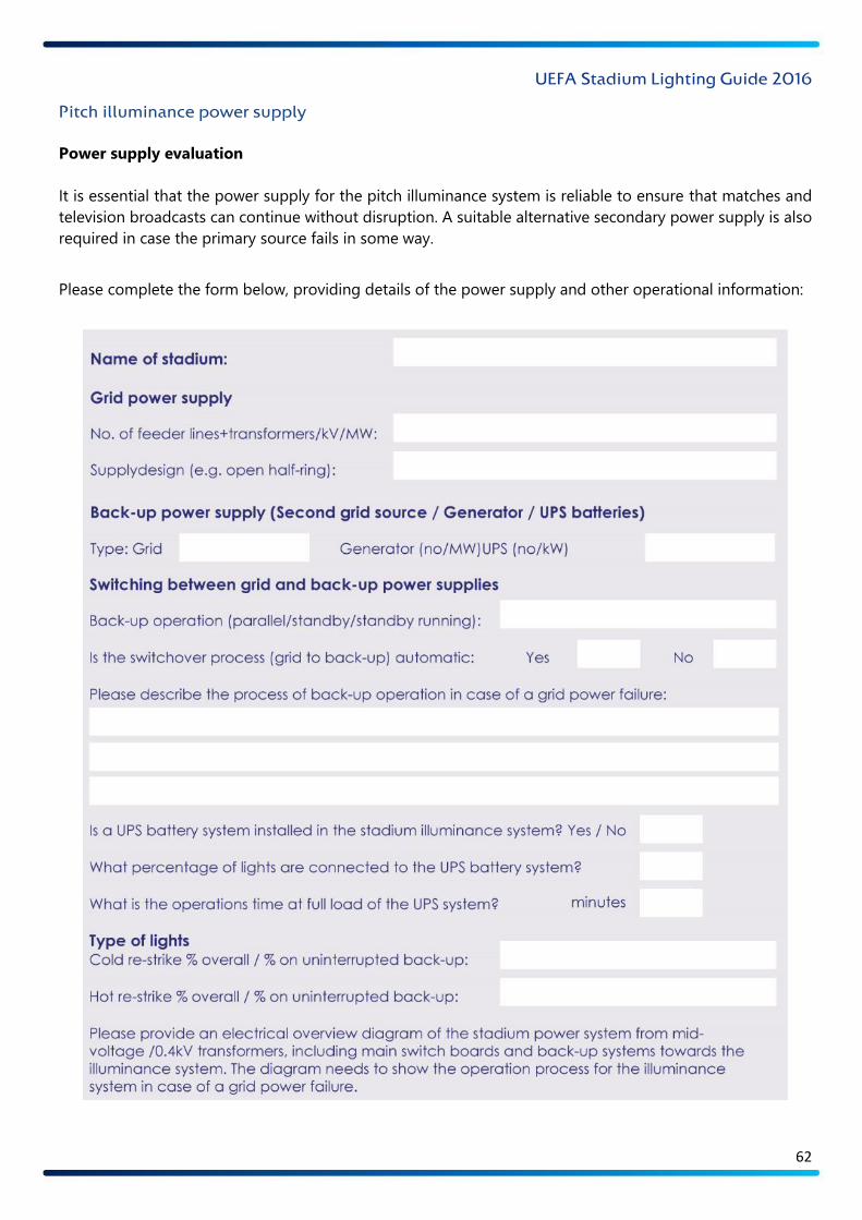
UEFA Stadium Lighting Guide 2016
62
Pitch illuminance power supply
Power supply evaluation
It is essential that the power supply for the pitch illuminance system is reliable to ensure that matches and
television broadcasts can continue without disruption. A suitable alternative secondary power supply is also
required in case the primary source fails in some way.
Please complete the form below, providing details of the power supply and other operational information:
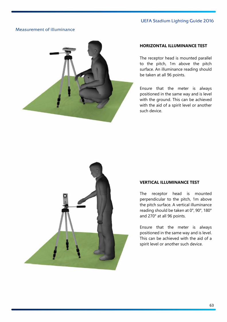
UEFA Stadium Lighting Guide 2016
63
Measurement of illuminance
HORIZONTAL ILLUMINANCE TEST
The receptor head is mounted parallel
to the pitch, 1m above the pitch
surface. An illuminance reading should
be taken at all 96 points.
Ensure that the meter is always
positioned in the same way and is level
with the ground. This can be achieved
with the aid of a spirit level or another
such device.
VERTICAL ILLUMINANCE TEST
The receptor head is mounted
perpendicular to the pitch, 1m above
the pitch surface. A vertical illuminance
reading should be taken at 0°, 90°, 180°
and 270° at all 96 points.
Ensure that the meter is always
positioned in the same way and is level.
This can be achieved with the aid of a
spirit level or another such device.
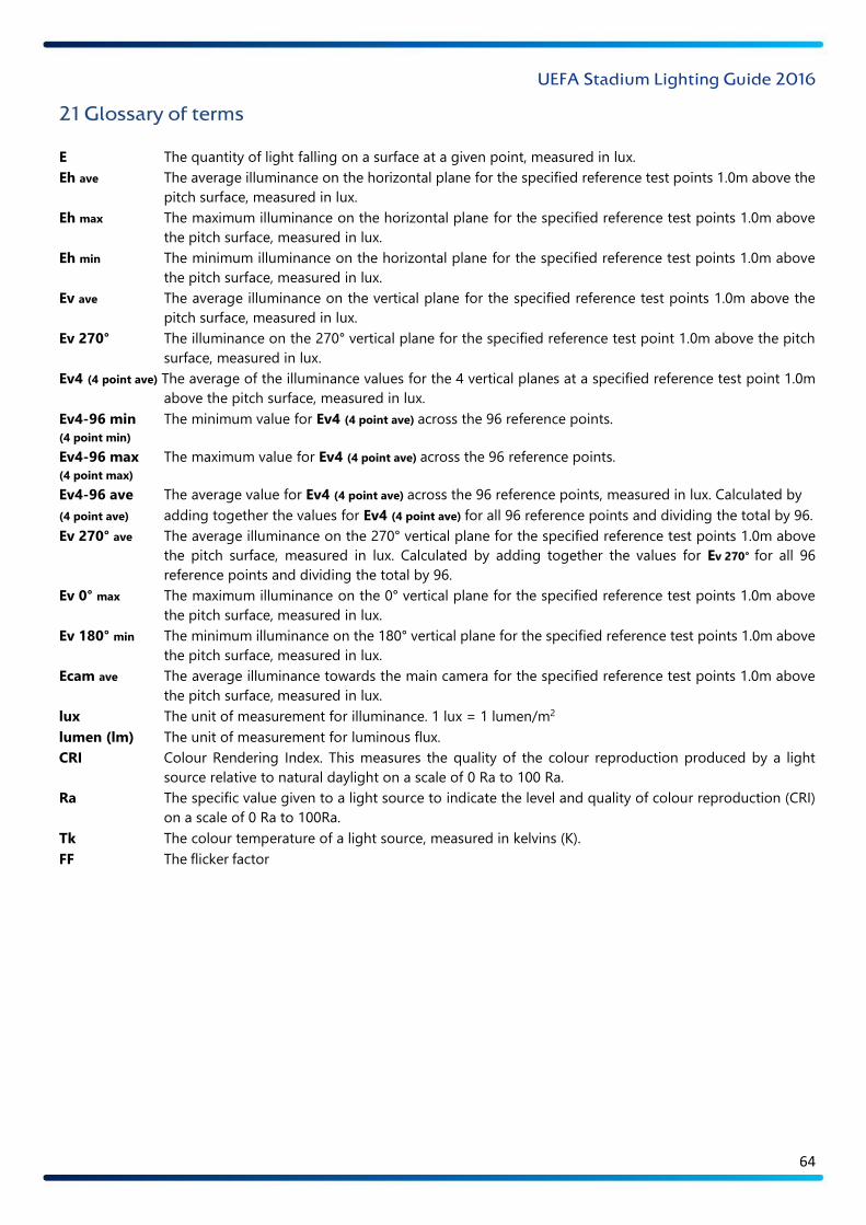
UEFA Stadium Lighting Guide 2016
64
21 Glossary of terms
E The quantity of light falling on a surface at a given point, measured in lux.
Eh ave The average illuminance on the horizontal plane for the specified reference test points 1.0m above the
pitch surface, measured in lux.
Eh max The maximum illuminance on the horizontal plane for the specified reference test points 1.0m above
the pitch surface, measured in lux.
Eh min The minimum illuminance on the horizontal plane for the specified reference test points 1.0m above
the pitch surface, measured in lux.
Ev ave The average illuminance on the vertical plane for the specified reference test points 1.0m above the
pitch surface, measured in lux.
Ev 270° The illuminance on the 270° vertical plane for the specified reference test point 1.0m above the pitch
surface, measured in lux.
Ev4 (4 point ave) The average of the illuminance values for the 4 vertical planes at a specified reference test point 1.0m
above the pitch surface, measured in lux.
Ev4-96 min The minimum value for Ev4 (4 point ave) across the 96 reference points.
(4 point min)
Ev4-96 max The maximum value for Ev4 (4 point ave) across the 96 reference points.
(4 point max)
Ev4-96 ave The average value for Ev4 (4 point ave) across the 96 reference points, measured in lux. Calculated by
(4 point ave) adding together the values for Ev4 (4 point ave) for all 96 reference points and dividing the total by 96.
Ev 270° ave The average illuminance on the 270° vertical plane for the specified reference test points 1.0m above
the pitch surface, measured in lux. Calculated by adding together the values for Ev 270° for all 96
reference points and dividing the total by 96.
Ev 0° max The maximum illuminance on the 0° vertical plane for the specified reference test points 1.0m above
the pitch surface, measured in lux.
Ev 180° min The minimum illuminance on the 180° vertical plane for the specified reference test points 1.0m above
the pitch surface, measured in lux.
Ecam ave The average illuminance towards the main camera for the specified reference test points 1.0m above
the pitch surface, measured in lux.
lux The unit of measurement for illuminance. 1 lux = 1 lumen/m2
lumen (lm) The unit of measurement for luminous flux.
CRI Colour Rendering Index. This measures the quality of the colour reproduction produced by a light
source relative to natural daylight on a scale of 0 Ra to 100 Ra.
Ra The specific value given to a light source to indicate the level and quality of colour reproduction (CRI)
on a scale of 0 Ra to 100Ra.
Tk The colour temperature of a light source, measured in kelvins (K).
FF The flicker factor – the modulation of luminance on a given plane during a complete cycle. This denotes
the relationship between the maximum luminance value and the minimum luminance value, expressed
as a percentage.
GR The glare rating – the degree of discomfort caused by the illuminance system to a person on the pitch.
The glare rating is calculated at a height of 1.75m above the pitch surface.
U1h A measure of horizontal uniformity of illuminance. The ratio of minimum horizontal illuminance to
maximum horizontal illuminance across all 96 reference points.
U2h A measure of horizontal uniformity of illuminance. The ratio of minimum horizontal illuminance to
average horizontal illuminance across all 96 reference points.
U1v A measure of vertical uniformity of illuminance. The ratio of minimum vertical illuminance to maximum
vertical illuminance on the given plane across all 96 reference points.
U2v A measure of vertical uniformity of illuminance. The ratio of minimum vertical illuminance to average
vertical illuminance on the given plane across all 96 reference points.
U1v A measure of vertical illuminance and illuminance modelling uniformity. The ratio of Ev4 (4 point min)
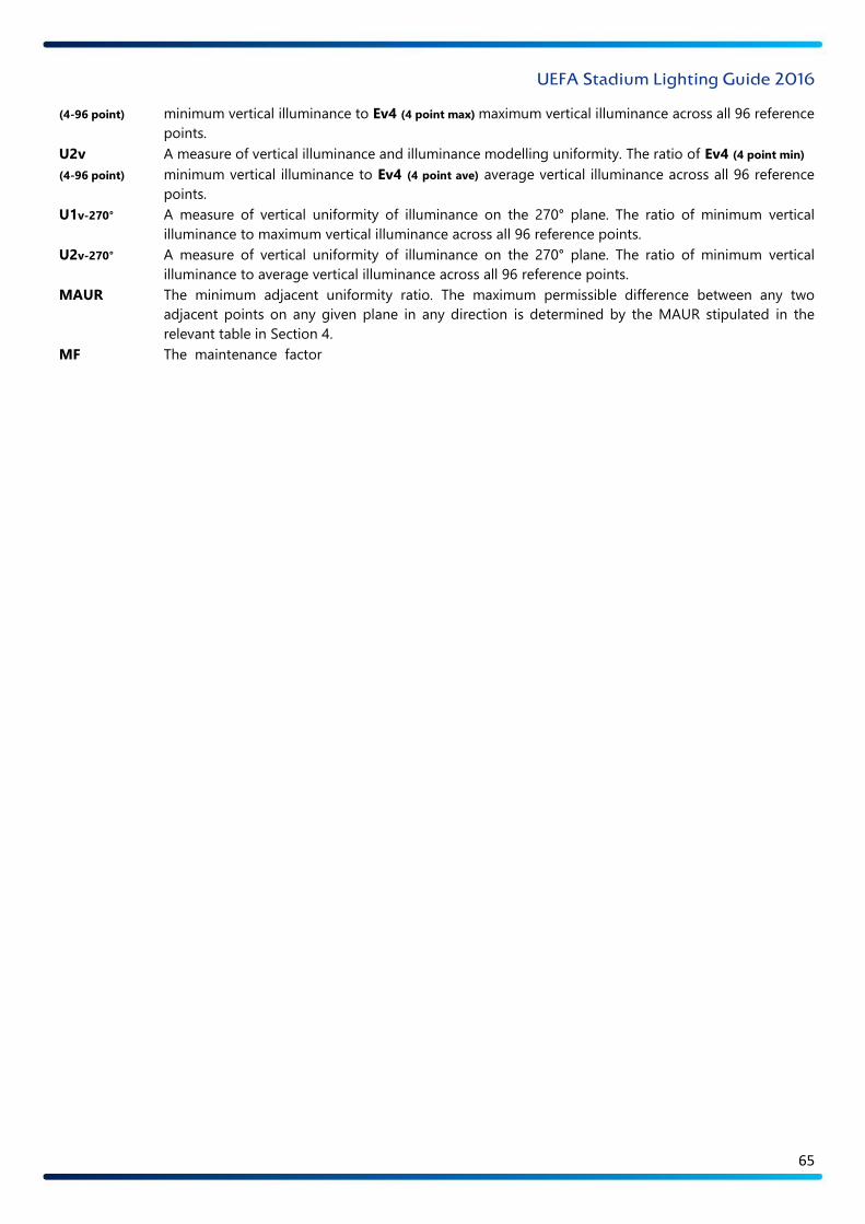
UEFA Stadium Lighting Guide 2016
65
(4-96 point) minimum vertical illuminance to Ev4 (4 point max) maximum vertical illuminance across all 96 reference
points.
U2v A measure of vertical illuminance and illuminance modelling uniformity. The ratio of Ev4 (4 point min)
(4-96 point) minimum vertical illuminance to Ev4 (4 point ave) average vertical illuminance across all 96 reference
points.
U1v-270° A measure of vertical uniformity of illuminance on the 270° plane. The ratio of minimum vertical
illuminance to maximum vertical illuminance across all 96 reference points.
U2v-270° A measure of vertical uniformity of illuminance on the 270° plane. The ratio of minimum vertical
illuminance to average vertical illuminance across all 96 reference points.
MAUR The minimum adjacent uniformity ratio. The maximum permissible difference between any two
adjacent points on any given plane in any direction is determined by the MAUR stipulated in the
relevant table in Section 4.
MF The maintenance factor – a factor used to calculate the deterioration of lamps and luminaires’
performance.
UPS An uninterruptible power supply – a power system providing instantaneous power (normally by means
of energy stored in batteries) in the event that the primary power source fails.
PISM Pitch illuminance switch mode. The pitch illuminance system should be pre-programmed with various
different modes, catering for a number of different situations. The number of modes may vary from
stadium to stadium.
FMM Full match mode. This involves the complete pitch illuminance system operating in match conditions
for the relevant UEFA illuminance level.
MCM Match continuity mode. This is the mode that is engaged to allow a match to continue after the primary
power supply has failed. In terms of the uniformity of illuminance, only U1 is evaluated. It should be
greater than 0.5 on the horizontal plane and 0.4 on the vertical plane.
TM Training mode. This mode provides sufficient pitch illuminance for training requirements.
MM Maintenance mode. This mode provides sufficient pitch illuminance for maintenance requirements.
Main camera side
This indicates the plane of the main camera position for a television broadcast. The main TV camera will be positioned
on the TV camera gantry. This is used in this guide to ensure that the pitch orientation is correct and consistent for all
stadiums. The main camera side is also referred to as the 270° plane.
Main camera position
This indicates the position of the main camera for a television broadcast. The main TV camera will be positioned on the
TV camera gantry. This is used in this guide to ensure that the pitch orientation is correct and consistent for all stadiums.

UEFA Stadium Lighting Guide 2016
66