ufgs 23 51 43.01 20 mechanical cyclone dust collector of ... 23 51 43.01 20.pdf · 10 microns in...
TRANSCRIPT

**************************************************************************USACE / NAVFAC / AFCEC / NASA UFGS- 23 51 43. 01 20 ( Apr i l 2006) - - - - - - - - - - - - - - - - - - - - - - - - - - - - - - - -Pr epar i ng Act i v i t y: NAVFAC Repl aci ng wi t hout change UFGS- 15861N ( Sept ember 1999)
UNI FI ED FACI LI TI ES GUI DE SPECI FI CATI ONS
Ref er ences ar e i n agr eement wi t h UMRL dat ed Januar y 2020**************************************************************************
SECTION TABLE OF CONTENTS
DIVISION 23 - HEATING, VENTILATING, AND AIR CONDITIONING (HVAC)
SECTION 23 51 43.01 20
MECHANICAL CYCLONE DUST COLLECTOR OF FLUE GAS PARTICULATES
04/06
PART 1 GENERAL
1.1 REFERENCES 1.2 SYSTEM DESCRIPTION 1.3 PERFORMANCE 1.4 DESIGN REQUIREMENTS 1.4.1 Mechanical Cyclone Dust Collector System 1.5 OPERATING EXPERIENCE REQUIREMENTS 1.5.1 Equipment 1.5.2 Operating Experience 1.6 MANUFACTURER'S FIELD REPRESENTATIVE 1.7 RELATED REQUIREMENTS 1.8 SUBMITTALS 1.9 QUALITY ASSURANCE 1.9.1 Lists of Prior Installations 1.9.2 Certification of Testing Capability 1.9.3 Voltage Testing Certificate 1.10 BID FORMS 1.11 DELIVERY AND ASSEMBLY 1.11.1 Coordination 1.12 DATA AND CONDITIONS 1.12.1 Boiler Data 1.12.2 Inlet Gas Conditions 1.12.3 Dust Collector Data
PART 2 PRODUCTS
2.1 MATERIALS 2.2 FABRICATION 2.2.1 Structural Supports 2.2.2 Hoppers 2.2.2.1 Hopper Accessories 2.2.2.2 Hopper Vibrators 2.2.3 Multitube Collector Collecting and Outlet Tubes 2.2.4 Hopper Heating Systems 2.2.4.1 Hopper Heater System Design
SECTION 23 51 43.01 20 Page 1

2.2.4.2 Hopper Heater Controls 2.2.5 Fly Ash Level Alarms 2.2.5.1 Hopper Source and Access Door 2.2.5.2 Hopper Level Signals 2.2.6 Ductwork 2.2.6.1 Ductwork to Cyclones 2.2.6.2 Flue Gas Velocity 2.2.7 Draft Connections 2.2.8 Inlet Manifold and Dampers 2.2.9 Access 2.2.9.1 Access Structures and Fixtures 2.2.9.2 Access Doors 2.2.10 Insulation and Casing 2.2.10.1 Insulation Material 2.2.10.2 Casing Materials 2.3 SAMPLING PORTALS
PART 3 EXECUTION
3.1 INSTALLATION 3.2 INSULATION INSTALLATION 3.2.1 Block and Mineral Fiberboard Insulation Installation 3.2.2 Mineral Fiber Blanket Insulation 3.3 CASING INSTALLATION 3.3.1 Structural Steel Grid System 3.3.2 Access Openings 3.3.3 Weatherproofing 3.3.4 Convection Stops 3.3.5 Casing Attachment 3.4 HOPPER HEATER SYSTEM 3.5 GALVANIC CORROSION 3.6 PROTECTION FROM INSULATION MATERIALS 3.7 INSPECTIONS AND TESTS 3.7.1 Factory Inspection 3.7.2 Field Inspection and Tests 3.7.2.1 Delivery Inspection 3.7.2.2 Post-Installation Inspection of Dust Collectors 3.7.2.3 Performance Test of Dust Collectors 3.8 IDENTIFICATION 3.9 PAINTING 3.10 SCHEDULE
-- End of Section Table of Contents --
SECTION 23 51 43.01 20 Page 2
**************************************************************************USACE / NAVFAC / AFCEC / NASA UFGS- 23 51 43. 01 20 ( Apr i l 2006) - - - - - - - - - - - - - - - - - - - - - - - - - - - - - - - -Pr epar i ng Act i v i t y: NAVFAC Repl aci ng wi t hout change UFGS- 15861N ( Sept ember 1999)
UNI FI ED FACI LI TI ES GUI DE SPECI FI CATI ONS
Ref er ences ar e i n agr eement wi t h UMRL dat ed Januar y 2020**************************************************************************
SECTION 23 51 43.01 20
MECHANICAL CYCLONE DUST COLLECTOR OF FLUE GAS PARTICULATES04/06
**************************************************************************NOTE: Thi s gui de speci f i cat i on cover s t he r equi r ement s f or f ur ni shi ng, i nst al l i ng, adj ust i ng, and t est i ng of mechani cal cycl one- t ype dust collector(s).
Adher e t o UFC 1-300-02 Uni f i ed Faci l i t i es Gui de Speci f i cat i ons ( UFGS) For mat St andar d when edi t i ng t hi s gui de speci f i cat i on or pr epar i ng new pr oj ect speci f i cat i on sect i ons. Edi t t hi s gui de speci f i cat i on f or pr oj ect speci f i c r equi r ement s by addi ng, del et i ng, or r evi s i ng t ext . For br acket ed i t ems, choose appl i cabl e i t em( s) or i nser t appr opr i at e i nf or mat i on.
Remove i nf or mat i on and r equi r ement s not r equi r ed i n r espect i ve pr oj ect , whet her or not br acket s ar e present.
Comment s, suggest i ons and r ecommended changes f or t hi s gui de speci f i cat i on ar e wel come and shoul d be submi t t ed as a Criteria Change Request (CCR) .
**************************************************************************
**************************************************************************NOTE: The dust col l ect or s ar e i nt ended t o be used f or f l ue gas par t i cul at e r emoval and col l ect i on associ at ed wi t h coal - f i r ed or oi l - f i r ed boi l er s and r ef use- f i r ed wast e di sposal i nci ner at or s. Coal - f i r ed boi l er s appl i cabl e t o t hi s speci f i cat i on ar e t hose desi gned f or pul ver i zed coal f i r i ng, spr eader st oker f i r i ng, or under f eed st oker f i r i ng wi t h capaci t i es r angi ng bet ween 3. 78 and 44 ki l ogr am of st eam per second 30, 000 and 350, 000 pounds of st eam per hour . The i nci ner at or s appl i cabl e t o t hi s speci f i cat i on ar e t hose desi gned f or bur ni ng muni ci pal - t ype wast e havi ng f i r i ng capaci t i es bet ween 454 ki l ogr am per hour 1, 000 pounds per hour and 182 Mg 200 t ons per day.
**************************************************************************
**************************************************************************
SECTION 23 51 43.01 20 Page 3

NOTE: The f ol l owi ng i nf or mat i on shal l be shown on t he pr oj ect dr awi ngs:
1. The physi cal geomet r y of t he cycl one r el at i ve t o t he pl ant .
2. The manner i n whi ch t he cycl one i s connect ed t o t he duct wor k.
3. The means of physi cal suppor t of t he cycl one.
4. The amount of c l ear ance bet ween t he hopper and floor.
**************************************************************************
PART 1 GENERAL
1.1 REFERENCES
**************************************************************************NOTE: Thi s par agr aph i s used t o l i s t t he publ i cat i ons c i t ed i n t he t ext of t he gui de speci f i cat i on. The publ i cat i ons ar e r ef er r ed t o i n t he t ext by basi c desi gnat i on onl y and l i s t ed i n t hi s par agr aph by or gani zat i on, desi gnat i on, dat e, and t i t l e. Use t he Ref er ence Wi zar d' s Check Ref er ence f eat ur e when you add a Ref er ence I dent i f i er ( RI D) out si de of t he Sect i on' s Ref er ence Ar t i c l e t o aut omat i cal l y pl ace t he r ef er ence i n t he Ref er ence Ar t i c l e. Al so use t he Ref er ence Wi zar d' s Check Ref er ence f eat ur e t o updat e t he i ssue dat es. Ref er ences not used i n t he t ext wi l l aut omat i cal l y be del et ed f r om t hi s sect i on of t he pr oj ect speci f i cat i on when you choose t o r econci l e r ef er ences i n t he publ i sh pr i nt pr ocess.
**************************************************************************
The publications listed below form a part of this specification to the extent referenced. The publications are referred to within the text by the basic designation only.
ASTM INTERNATIONAL (ASTM)
ASTM A36/A36M (2014) Standard Specification for Carbon Structural Steel
ASTM A123/A123M (2017) Standard Specification for Zinc (Hot-Dip Galvanized) Coatings on Iron and Steel Products
ASTM A139/A139M (2016) Standard Specification for Electric-Fusion (ARC)-Welded Steel Pipe (NPS 4 and over)
ASTM A167 (2011) Standard Specification for Stainless and Heat-Resisting
SECTION 23 51 43.01 20 Page 4

Chromium-Nickel Steel Plate, Sheet, and Strip
ASTM A240/A240M (2018) Standard Specification for Chromium and Chromium-Nickel Stainless Steel Plate, Sheet, and Strip for Pressure Vessels and for General Applications
ASTM A242/A242M (2013; R 2018) Standard Specification for High-Strength Low-Alloy Structural Steel
ASTM A532/A532M (2010; R 2019) Standard Specification for Abrasion-Resistant Cast Irons
ASTM A580/A580M (2018) Standard Specification for Stainless Steel Wire
ASTM A667/A667M (1987; R 2018) Standard Specification for Centrifugally Cast Dual Metal (Gray and White Cast Iron) Cylinders
ASTM B209 (2014) Standard Specification for Aluminum and Aluminum-Alloy Sheet and Plate
ASTM B209M (2014) Standard Specification for Aluminum and Aluminum-Alloy Sheet and Plate (Metric)
ASTM C401 (2012) Alumina and Alumina-Silicate Castable Refractories
ASTM C592 (2016) Standard Specification for Mineral Fiber Blanket Insulation and Blanket-Type Pipe Insulation (Metal-Mesh Covered) (Industrial Type)
ASTM C612 (2014; R 2019) Mineral Fiber Block and Board Thermal Insulation
INSTITUTE OF CLEAN AIR COMPANIES (ICAC)
ICAC M-2 (1969) Cyclonic Mechanical Dust Collector Criteria
ICAC M-4 (1973) Information Required for the Preparation of Bidding Specifications for Large Diameter Cyclones and Tubular Centrifugal Collectors
ICAC M-5 (1975) Standardized Method of Particle Size Determination and Collection Efficiency
ICAC M-6 (1981) Simplified Method of Efficiency Calculations from Fractional Efficiency Curves
NATIONAL ELECTRICAL MANUFACTURERS ASSOCIATION (NEMA)
NEMA ICS 6 (1993; R 2016) Industrial Control and
SECTION 23 51 43.01 20 Page 5

Systems: Enclosures
SHEET METAL AND AIR CONDITIONING CONTRACTORS' NATIONAL ASSOCIATION (SMACNA)
SMACNA 1403 (2008) Accepted Industry Practice for Industrial Duct Construction, 2nd Edition
SOCIETY FOR PROTECTIVE COATINGS (SSPC)
SSPC SP 6/NACE No.3 (2007) Commercial Blast Cleaning
SSPC SSPM (2010) SSPC Painting Manual, Volume 2, Systems and Specifications
U.S. GENERAL SERVICES ADMINISTRATION (GSA)
FS TT-P-28 (Rev H) Paint, Aluminum, Heat Resisting (1200 Degrees F.)
U.S. NATIONAL ARCHIVES AND RECORDS ADMINISTRATION (NARA)
29 CFR 1910-SUBPART D Walking - Working Surfaces
40 CFR 60 Standards of Performance for New Stationary Sources
1.2 SYSTEM DESCRIPTION
**************************************************************************NOTE: Sel ect t he appl i cabl e par agr aph( s) f r om t he following:
**************************************************************************
**************************************************************************NOTE: Use t hese par agr aphs f or mul t i t ube col l ect or s 150 mm 6 i nch di amet er col l ect i ng t ubes may cause a pl uggi ng pr obl em. Desi gner must i nvest i gat e f l ue gas par t i cul at e s i ze, di st r i but i on and t endency of par t i cul at es t o adher e t o each ot her f or t he speci f i c pr oj ect bef or e sel ect i ng di amet er of col l ect or t ubes.
**************************************************************************
**************************************************************************NOTE: The t hi r d sent ence of t hi s par agr aph shal l be used onl y when dust col l ect or i s used wi t h spr eader st oker - f i r ed boi l er .
**************************************************************************
[Dust collector(s) shall be multitube, mechanical cyclone type, having collector tubes in accordance with ICAC M-2 , ICAC M-4 , ICAC M-5 , and ICAC M-6 . Collector(s) shall remove fly-ash from flue gas produced by a [pulverized coal-fired boiler] [spreader stoker-fired boiler] [underfeed stoker-fired boiler] [No. 6 fuel oil fired boiler] [refuse fired waste disposal incinerator of water wall furnace design]. [There shall not be any reinjection from dust collector hopper(s) into spreader stoker-fired boiler.] Collector(s) shall be designed for [indoor] [outdoor] installation and located in the flue-gas system between [_____] outlet and
SECTION 23 51 43.01 20 Page 6
[_____] inlet [existing] locations. Provide necessary gas distribution devices in the ductwork ahead of and at the entrance of the dust collector(s) to ensure even gas flow into the dust collector(s).]
**************************************************************************NOTE: Use t hi s par agr aph f or 600 mm 24 i nch or l ar ger di amet er cycl one col l ect or s. A choi ce of di amet er i s dependent upon desi gn par amet er s t hat must be anal yzed.
**************************************************************************
[Dust collector(s) shall be high-efficiency, mechanical cyclone-type, [600 mm] [24 inch] [_____] diameter centrifugal cyclone body with tangential entry having arrangements of one, two, four, or more parallel unit combinations in accordance with ICAC M-2 , ICAC M-4 , ICAC M-5 , and ICAC M-6 . Collector(s) shall remove fly ash from flue gas produced by a refuse fired waste disposal incinerator of the no-boiler furnace design. Collector(s) shall be designed for [indoor] [outdoor] installation and located in the flue gas system between [_____] outlet and [_____] inlet [existing] locations. Provide necessary gas distribution devices in the ductwork ahead of and at the entrance of the dust collector(s) to ensure even gas flow into the dust collector(s).]
1.3 PERFORMANCE
**************************************************************************NOTE:
1. The st ack emi ssi on or ef f i c i ency r equi r ement must compl y wi t h ei t her ( a) wei ght emi ssi on st andar ds: ( b) opaci t y r egul at i ons; or ( c) communi t y st andar ds f or v i s i bl e emi ssi ons. Compl i ance wi t h exi st i ng emi ssi on codes may not sat i sf y t he opaci t y r egul at i on. Si mi l ar l y opaci t y r egul at i ons may not be as demandi ng as communi t y st andar ds. A speci f i c quant i t at i ve emi ssi on r at e must be sel ect ed on t he basi s of t he goal s est abl i shed.
2. St ack opaci t y i s i nf l uenced by par t i c l e s i ze makeup. For exampl e, wi t h pul ver i zed coal - f i r ed boi l er s, about 45 per cent of ash par t i c l es ar e bel ow 10 mi cr ons i n s i ze; f or a cycl one- f i r ed boi l er , about 70 per cent ar e bel ow 10 mi cr ons; f or a st oker - f i r ed boi l er , about 25 per cent ar e bel ow 10 mi cr ons. A v i sual l y accept abl e st ack f or t hese t hr ee opt i ons mi ght r equi r e r esi dual s of 0. 046 g/ m3 0. 02 gr per cf , 0. 023 g/ m3 0. 01 gr per cf , and 0. 0929 g/ m3 0. 04 gr per cf , r espect i vel y.
3. A 90 per cent over al l col l ect i on ef f i c i ency may be at t ai nabl e wi t h most coal s bur ned i n under f eed or gr avi t y f eed st oker - f i r ed boi l er s. Mechani cal cycl ones must be vi ewed as a par t of an ai r pol l ut i on syst em on boi l er s or i nci ner at or s. When used as pr ecl eaner s i n conj unct i on wi t h el ect r ost at i c pr eci pi t at or s ( ESP) or baghouses, a hi gh ef f i c i ency cycl one i s not necessar y and may even adver sel y af f ect t he hi gh ef f i c i enci es of t he ESP or baghouse. I n addi t i on, 90 per cent ef f i c i ency
SECTION 23 51 43.01 20 Page 7

i s dependent upon par t i c l e s i ze, di st r i but i on and concent r at i on as wel l as t he col l ect or bei ng or not bei ng used i n conj unct i on wi t h hi gher ef f i c i ency ESP or baghouse col l ect or s. The l ar ge di amet er cycl ones do have a l ow pr essur e dr op, but t he hi gh ef f i c i ent mul t i t ube col l ect or s oper at e i n a r ange f r om 747 t o 1992 Pa 3 t o 8 i nches wat er gage.
**************************************************************************
[Multitube] [Centrifugal cyclone] collector shall operate with a minimum overall collection efficiency of [_____] percent at a maximum draft loss of [1992] [249] Pa [8] [1] [_____] inch water gage when operating at maximum [continuous] [peak] rating of flue gas flow conditions, dust loading, and dust particle size distribution specified in paragraph entitled "Inlet Gas Conditions."
1.4 DESIGN REQUIREMENTS
1.4.1 Mechanical Cyclone Dust Collector System
Indicate the kind, size, collector arrangement with duct gas distribution devices, duct transitions, hopper access, walkways, housing access, damper and damper controls, draft gage and sample portal connections, weight of each component, and breakdown for shipment. When detail drawings are submitted without statements describing sectional shipments, it will be understood that no field assembly of the equipment will be required. Indicate the arrangement of platforms, walkways, stairways, and fixed ladders that are required for operation, examination, testing and maintenance of each dust collector. Indicate the external connections, location of local controls and remote control panels, anchorages, and supports required; the dimensions needed for installation and correlation with other materials and equipment; and foundation and loading information. Submit the layout drawings for each component showing design and assembly. Layout drawings shall show each hopper face with all arrangement including control zones. Submit wiring diagrams and control schematics of all electrical and pneumatic circuits used.
1.5 OPERATING EXPERIENCE REQUIREMENTS
1.5.1 Equipment
Provide only [a] dust collector[s] which meet[s] all of the operating experience requirements listed below.
1.5.2 Operating Experience
Manufacturer shall certify that the manufacturer has constructed not less than three mechanical cyclone type dust collectors of the [multitube mechanical type] [high-efficiency; large-diameter centrifugal cyclone type] treating flue gas from [an incinerator] [a boiler] with [automatic] [manual] combustion control. Each collector shall have performed satisfactorily, normal maintenance or downtime of the associated [boiler] [incinerator] included, for a period of not less than 2 years treating at least [_____] L/s acfm of inlet gas at a temperature of at least [_____] degrees C F , with inlet dust loading of at least [_____] grams per liter grains per acf and outlet dust loading of at most [_____] grams per liter grains per acf . In determining this experience:
a. Only collection of fly ash as produced by [coal-fired boilers]
SECTION 23 51 43.01 20 Page 8

[oil-fired boilers] [refuse-fired waste disposal incinerator] is considered as equivalent experience.
b. Only experience at the approximate flow gas volume, flue gas temperature and inlet dust loading is acceptable.
1.6 MANUFACTURER'S FIELD REPRESENTATIVE
Furnish the services of [a] field representative(s) specifically trained by the manufacturer to assist installers of their equipment. Field representative(s) shall be at the erection site during all phases of the installation including unloading, hauling, storing, cleaning, erecting, and testing. It is the responsibility of the field representative(s) to assist the installer during the erection of [the] dust collector(s) and to assure both parties that dust collector(s) [is] [are] being installed in accordance with the dust collector manufacturer's recommendations. The field representative(s) shall certify in writing to the Contracting Officer that dust collector(s) [has] [have] been installed as recommended by the manufacturer. The field representative(s) shall supervise the adjustment of all controls, control devices, and components supplied with dust collector(s) as necessary to place dust collector(s) in successful operation. Field representative(s) shall instruct plant operators in operation, care, and maintenance of the dust collector(s). Written notice from the Contracting Officer shall be received prior to scheduling these instructions. The field representative[s] services will be required for approximately [3] [_____] days and will include [2] [_____] round trips to the job site.
1.7 RELATED REQUIREMENTS
Section 23 03 00.00 20 BASIC MECHANICAL MATERIALS AND METHODS, shall apply.
1.8 SUBMITTALS
**************************************************************************NOTE: Revi ew Submi t t al Descr i pt i on ( SD) def i ni t i ons i n Sect i on 01 33 00 SUBMI TTAL PROCEDURES and edi t t he f ol l owi ng l i s t t o r ef l ect onl y t he submi t t al s r equi r ed f or t he pr oj ect .
The Gui de Speci f i cat i on t echni cal edi t or s have desi gnat ed t hose i t ems t hat r equi r e Gover nment appr oval , due t o t hei r compl exi t y or cr i t i cal i t y, wi t h a " G" . Gener al l y, ot her submi t t al i t ems can be r evi ewed by t he Cont r act or ' s Qual i t y Cont r ol Syst em. Onl y add a “ G” t o an i t em, i f t he submi t t al i s suf f i c i ent l y i mpor t ant or compl ex i n cont ext of t he pr oj ect .
For submi t t al s r equi r i ng Gover nment appr oval on Ar my pr oj ect s, a code of up t o t hr ee char act er s wi t hi n t he submi t t al t ags may be used f ol l owi ng t he " G" desi gnat i on t o i ndi cat e t he appr ovi ng aut hor i t y. Codes f or Ar my pr oj ect s usi ng t he Resi dent Management Syst em ( RMS) ar e: " AE" f or Ar chi t ect - Engi neer ; " DO" f or Di st r i ct Of f i ce ( Engi neer i ng Di v i s i on or ot her or gani zat i on i n t he Di st r i ct Of f i ce) ; " AO" f or Ar ea Of f i ce; " RO" f or Resi dent Of f i ce; and " PO" f or Pr oj ect Of f i ce. Codes
SECTION 23 51 43.01 20 Page 9

f ol l owi ng t he " G" t ypi cal l y ar e not used f or Navy, Ai r For ce, and NASA pr oj ect s.
The " S" f ol l owi ng a submi t t al i t em i ndi cat es t hat t he submi t t al i s r equi r ed f or t he Sust ai nabi l i t y eNot ebook t o f ul f i l l f eder al l y mandat ed sust ai nabl e r equi r ement s i n accor dance wi t h Sect i on 01 33 29 SUSTAI NABI LI TY REPORTI NG. Locat e t he " S" submi t t al under t he SD number t hat best descr i bes t he submi t t al i t em.
Choose t he f i r st br acket ed i t em f or Navy, Ai r For ce and NASA pr oj ect s, or choose t he second br acket ed i t em f or Ar my pr oj ect s.
**************************************************************************
Government approval is required for submittals with a "G" designation; submittals not having a "G" designation are [for Contractor Quality Control approval.][for information only. When used, a designation following the "G" designation identifies the office that will review the submittal for the Government.] Submittals with an "S" are for inclusion in the Sustainability eNotebook, in conformance to Section 01 33 29 SUSTAINABILITY REPORTING. Submit the following in accordance with Section 01 33 00 SUBMITTAL PROCEDURES:
SD-03 Product Data
[ Centrifugal cyclone collector ]
[ Multitube collector ]
Submit performance curves consisting of particle size distribution and fractional efficiency curves.
SD-02 Shop Drawings
Mechanical cyclone dust collector system
SD-07 Certificates
Lists of prior installations
Certification of testing capability
SD-06 Test Reports
Voltage testing certificate
Post-installation inspection of dust collectors
Performance test of dust collectors
Particulate tests of dust collectors
Submit post installation inspection report within 15 calendar days after inspection stating the findings including a statement that [the] mechanical dust collector(s) [are] [are not] acceptable for field performance tests. Perform dust collector tests in conjunction with boiler or incinerator. For each performance test,
SECTION 23 51 43.01 20 Page 10

including cycling test and 100 percent load testing, submit data specified in paragraph entitled "Inlet Gas Conditions" and paragraph entitled "Dust Collector Data." Depict deficiencies and failures of components in test reports. Test reports for particulators tests shall certify that instruments were calibrated and readings indicated are true, that computations required for testing are accurate, that acceptable methods were used, and that the equipment performed in accordance with the requirements or performed with depicted failures or deficiencies. Results of additional tests shall be recorded and submitted in a written report to the Contracting Officer.
SD-10 Operation and Maintenance Data
Centrifugal cyclone collector , Data Package 3
Multitube collector , Data Package 3
Submit in accordance with Section 01 78 23 OPERATION AND MAINTENANCE DATA. Include complete installation, operation and maintenance instructions and data including models and serial numbers and part lists for the equipment.
1.9 QUALITY ASSURANCE
1.9.1 Lists of Prior Installations
Submit within 30 days after award and prior to commencement of installation, a certificate containing the following information:
a. A list of at least three installations meeting requirements set forth in paragraph entitled "Operating Experience."
b. Owner and location of each installation.
c. Date of owner acceptance of each installation.
d. Collector model number.
e. Design inlet gas volume, L/s acfm .
f. Design inlet gas temperature, degrees C F .
g. Design inlet dust loading, grams per liter grains per acf .
h. Design outlet dust loading grams per liter grains per acf .
i. Type of [coal-fired] [oil-fired] [boiler] [refuse-fired waste disposal incinerator].
1.9.2 Certification of Testing Capability
Certify that the factory is capable of performing electrical integrity tests of 1000 volts for hopper heater modules, blanket or tape.
1.9.3 Voltage Testing Certificate
Submit test.
SECTION 23 51 43.01 20 Page 11

1.10 BID FORMS
ICAC M-4 evaluation bid forms.
1.11 DELIVERY AND ASSEMBLY
Ship equipment completely factory-assembled, except when physical size, arrangement, or configuration of the equipment, or shipping limitations, makes the shipment of completely assembled equipment impracticable, in which case assemble equipment and ship as shown on the approved shop drawings. The Contractor is responsible for all costs encountered in the field for assembly of sections, accessories, or appurtenances not listed in the proposal as requiring field assembly.
1.11.1 Coordination
Contractor shall ensure that design parameters of collector are coordinated by dust collector manufacturer with manufacturers of system equipment and installing contractor of ductwork with gas distribution devices which will interface with, and optimize system operation.
1.12 DATA AND CONDITIONS
1.12.1 Boiler Data
**************************************************************************NOTE: Sel ect t he appl i cabl e par agr aph( s) f r om t he following:
**************************************************************************
**************************************************************************NOTE: Dependi ng on ai r pol l ut i on emi ssi on r egul at i ons, mechani cal cycl one- t ype dust col l ect or s shoul d not be used al one on pul ver i zed coal - f i r ed boi l er s. They shoul d be used wi t h, and ahead of , el ect r ost at i c pr eci pi t at or s. Speci f y r ange of pr oper t i es f or coal . I f ot her ai r pol l ut i on equi pment exi st s or i s pr oposed, l i s t : descr i pt i on, t ype, r at i ng, per f or mance, condi t i on, expect ed l i f e and how t o be used wi t h new equi pment .
**************************************************************************
**************************************************************************NOTE: I nser t appr opr i at e Sect i on number and t i t l e i n t he bl anks bel ow usi ng f or mat per UFC 1- 300- 02.
**************************************************************************
Design mechanical cyclone-type dust collectors for operation with [the boiler(s) specified in [_____]] [boiler(s) manufactured by [_____], Type [_____], Model No. [_____]]. The boiler is a [new] [existing] [pulverized coal-fired] [spreader stoker-fired] [underfeed stoker-fired] [No. 6 fuel oil fired] boiler rated [_____] kilogram per second of steam at [_____] kPa pounds per hour of steam at [_____] psi , having a gross heat input of [_____] kilowatt million Btu per hour , and utilizing coal with the following approximate properties:
a. Proximate analysis, as received, percent by weight:
SECTION 23 51 43.01 20 Page 12

Range
Moisture [_____]
Ash [_____]
Volatile Matter [_____]
Fixed Carbon [_____]
Sulfur, percent by weight [_____]
Heating Value, Btu per pound [_____]
b. Ultimate analysis, as received, percent by weight
Range
Moisture [_____]
Carbon [_____]
Hydrogen [_____]
Sulfur [_____]
Nitrogen [_____]
Oxygen [_____]
Ash [_____]
Expected range of boiler steam output will be between [_____] and [_____] pounds per hour with peak loads only between [_____] and [_____] hours. Proposed or other existing gas cleaning equipment includes [_____]. Boiler combustion is controlled [manually] [automatically]. The standby fuel is [_____].
[Incinerator Data
**************************************************************************NOTE:
1. The st andar d c l assi f i cat i on of wast es i s as follows:
SECTION 23 51 43.01 20 Page 13

CLASSIFICATION
Type Description Pr i nci pl e Component s Noncombustible Sol i ds ( Max. Per cent by Weight
Moisture Content (Max. Percent)
Heating Val ue ( kJ per kg)
0 Trash Hi ghl y combust i bl e wast e, paper , wood, car dboar d car t ons, i ncl udi ng up t o 10 per cent t r eat ed paper , pl ast i c or r ubber scr ap, commer ci al and i ndust r i al sour ces
5 10 19,805
1 Rubbish Combust i bl e wast e paper , car t ons, r ags, wood scr aps, combust i bl e f l oor sweepi ngs, domest i c, commer ci al , and i ndust r i al sour ces
10 25 15,145
2 Refuse Rubbi sh and gar bage; r esi dent i al sour ces
7 50 10,019
3 Garbage Ani mal and veget abl e wast e, r est aur ant s, hot el s, mar ket s; institutional, commer ci al , and i ndust r i al sour ces
5 70 5825
4 Animal sol i ds and organic wastes
Car casses, or gans, sol i d or gani c wast es; hospi t al , l abor at or y, abat t oi r s, ani mal pounds, and si mi l ar sources
5 85 2330
Loose Paper - - 23,300
Loose Wood - - 23,300
Cl assi f i ed Mat er i al Highly-combustible wast e, paper , car dboar d car t ons i ncl udi ng up t o 10 per cent pl ast i cs and
- - 16, 310 t o 23,300
SECTION 23 51 43.01 20 Page 14

CLASSIFICATION
Type Description Pr i nci pl e Component s Noncombustible Sol i ds ( Max. Per cent by Weight
Moisture Content (Max. Percent)
Heating Value ( Bt u per Pound)
0 Trash Hi ghl y combust i bl e wast e, paper , wood, car dboar d car t ons, i ncl udi ng up t o 10 per cent t r eat ed paper , pl ast i c or r ubber scr ap, commer ci al and i ndust r i al sources
5 10 8,500
1 Rubbish Combust i bl e wast e paper , car t ons, r ags, wood scr aps, combust i bl e f l oor sweepi ngs, domest i c, commer ci al , and i ndust r i al sour ces
10 25 6,500
2 Refuse Rubbi sh and gar bage; r esi dent i al sour ces
7 50 4,300
3 Garbage Ani mal and veget abl e wast e, r est aur ant s, hot el s, mar ket s; institutional, commer ci al , and i ndust r i al sour ces
5 70 2,500
4 Animal sol i ds and organic wastes
Car casses, or gans, sol i d or gani c wast es; hospi t al , l abor at or y, abat t oi r s, ani mal pounds, and si mi l ar sour ces
5 85 1,000
Loose Paper - - 10,000
Loose Wood - - 10,000
Cl assi f i ed Mat er i al Hi ghl y- combust i bl e wast e, paper , car dboar d car t ons i ncl udi ng up t o 10 per cent pl ast i cs and t r eat ed paper
- - 7, 000 t o 10,000
2. I ncl ude ash anal ysi s i f avai l abl e. Cl assi f i ed
SECTION 23 51 43.01 20 Page 15

mat er i al cont ent s descr i pt i on may change as pl ast i c use i ncr eases. Check I nci ner at or I nst i t ut e of Amer i ca f or l at est i nf or mat i on.
**************************************************************************
**************************************************************************NOTE: I nser t appr opr i at e Sect i on number and t i t l e i n t he bl anks bel ow usi ng f or mat per UFC 1- 300- 02.
**************************************************************************
Design mechanical cyclone-type dust collector(s) for operation with [the incinerator(s) specified in [_____]] [incinerator(s) manufactured by [_____], Type [_____], Model No. [_____]]. The incinerator is a [new] [existing] installation capable of burning [_____] [ kilogram pounds ] per hour [ Mg tons per day] of type [0], [1], [2], [3], [4], [loose paper] [loose wood] [classified material] wastes. The expected range of incinerator operation will be between [_____] and [_____] [ kilogram pounds] per hour [ Mg tons per day] of wastes. Incinerator combustion is controlled [manually] [automatically]. Auxiliary fuel is [_____]. Proposed or other existing gas cleaning equipment includes [_____].]
1.12.2 Inlet Gas Conditions
**************************************************************************NOTE:
1. To pr oper l y appl y t hei r equi pment , t he dust col l ect or manuf act ur er must know t he expect ed i nl et gas condi t i ons. Thi s i nf or mat i on can best be suppl i ed by t he boi l er or i nci ner at or manuf act ur er .
2. I n det er mi ni ng t he i nl et gas condi t i ons f or exi st i ng i nst al l at i ons, sour ce t est i ng shoul d be per f or med t o det er mi ne t he gas f l ow and cont ent s. Gas vol ume det er mi nat i ons shoul d be made usi ng a Pi t ot t ube i n accor dance wi t h I CAC " Test Pr ocedur e, " Bul l et i n 101. Thi s publ i cat i on i ncor por at es ASME t echni ques as cal l ed f or i n ASME PTC 38 " Det er mi ni ng t he Concent r at i on of Par t i cul at e Mat t er i n a Gas St r eam. " For par t i cul at e l oadi ng an act ual sampl e shoul d be t aken and anal yzed i n accor dance wi t h ASME PTC 28, " Det er mi ni ng t he Pr oper t i es of Fi ne Par t i cul at e Mat t er " or i n accor dance wi t h EPA 40 CFR 60, Appendi x A, Met hod 5 or Met hod 17 or appl i cabl e l ocal st andar d.
3. I f of f - desi gn condi t i ons exi st , t he f ol l owi ng r el at i onshi ps ar e avai l abl e f or est i mat i on pur poses:
For Var i abl e Gas Fl ow Rat e:
100 - Ef f ( 1) = [ Q( 2) ] 0. 5100 - Ef f ( 2) [ Q( 1) ] 0. 5
For Const ant Gas Fl ow Rat e:
100 - Ef f ( 1) = [ U( 2) ] 0. 5100 - Ef f ( 2) [ U( 1) ] 0. 5
SECTION 23 51 43.01 20 Page 16

For Var i at i ons i n Gas Densi t y:
100 - Ef f ( 1) = [ Pp- Pg( 2) ] 0. 5100 - Ef f ( 2) [ Pp- Pg( 1) ] 0. 5
For Moder at e Changes I n Gas Par t i cul at e Loadi ngs:
100 - Ef f ( 1) = [ C( 2) ] 0. 183100 - Ef f ( 2) [ C( 1) ] 0. 183
Ef f : Col l ect or Ef f i c i encyPp: Par t i cul at e Densi t yQ: Vol ume Fl ow Rat ePg: Gas Densi t yU: Gas Vi scosi t yC: Par t i cul at e Concent r at i on1, 2: Oper at i ng Condi t i ons ( Mass Per Uni t Vol ume)
4. Mechani cal cycl one t ype dust col l ect or s shoul d be abl e t o handl e up t o 120 per cent of i nl et f l ue gas vol ume.
5. For new i nst al l at i ons, t he i nl et gas condi t i ons shoul d be obt ai ned f r om t he boi l er or i nci ner at or manuf act ur er . I f t hi s i s not possi bl e, t he gas cont ent s must be est i mat ed. When est i mat es ar e made, t he emi ssi on f act or s and handbook dat a shoul d be t aken f r om U. S. Envi r onment al Pr ot ect i on Agency publ i cat i on No. AP- 42, " Compi l at i on of Ai r Pol l ut ant Emi ssi on Fact or s" wi t h t he l at est suppl ement s.
**************************************************************************
**************************************************************************NOTE: Suppl y excess ai r per cent age f or i nci ner at or applications.
**************************************************************************
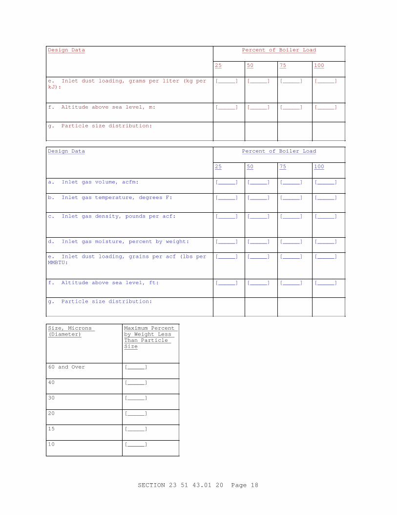
Design mechanical cyclone-type dust collector(s) for inlet gas conditions from the [boiler(s)] [incinerator(s)] specified above. Dust collector manufacturer shall coordinate the application of his equipment with the [boiler] [incinerator] manufacturer to assure that the collection efficiency specified herein is attained. The inlet gas conditions are:
Design Data Percent of Boiler Load
25 50 75 100
a. Inlet gas volume, L/s: [_____] [_____] [_____] [_____]
b. Inlet gas temperature, degrees C: [_____] [_____] [_____] [_____]
c. Inlet gas density, kilogram per cubic meter: [_____] [_____] [_____] [_____]
d. Inlet gas moisture, percent by weight: [_____] [_____] [_____] [_____]
SECTION 23 51 43.01 20 Page 17
Design Data Percent of Boiler Load
25 50 75 100
e. Inlet dust loading, grams per liter (kg per kJ):
[_____] [_____] [_____] [_____]
f. Altitude above sea level, m: [_____] [_____] [_____] [_____]
g. Particle size distribution:
Design Data Percent of Boiler Load
25 50 75 100
a. Inlet gas volume, acfm: [_____] [_____] [_____] [_____]
b. Inlet gas temperature, degrees F: [_____] [_____] [_____] [_____]
c. Inlet gas density, pounds per acf: [_____] [_____] [_____] [_____]
d. Inlet gas moisture, percent by weight: [_____] [_____] [_____] [_____]
e. Inlet dust loading, grains per acf (lbs per MMBTU:
[_____] [_____] [_____] [_____]
f. Altitude above sea level, ft: [_____] [_____] [_____] [_____]
g. Particle size distribution:
Size, Microns (Diameter)
Maximum Percent by Weight Less Than Particle Size
60 and Over [_____]
40 [_____]
30 [_____]
20 [_____]
15 [_____]
10 [_____]
SECTION 23 51 43.01 20 Page 18

Size, Microns (Diameter)
Maximum Percent by Weight Less Than Particle Size
60 and Over [_____]
7.5 [_____]
1.0 [_____]
0 to 1.0 [_____]
Total 100.0
h. Fly ash density for hopper volume design kilogram per cubic meter pounds per cubic foot : [640] [40] [_____]
i. Fly ash density for weight determination, kilogram per cubic meter pounds per cubic foot : [1440] [90] [_____]
j. Fly ash specific gravity: [_____]
k. Excess air (range): [_____]
Contractor shall verify data in the field and shall design the dust collector(s) to operate efficiently over the possible range of inlet gas conditions.
1.12.3 Dust Collector Data
The following design criteria shall apply to [each of] the dust collector(s). Applicable criteria shall be based on flow conditions at maximum continuous rating.
a. Minimum collection efficiency, percent [_____].
b. Gas velocity range through dust collector, m/s fps [_____].
c. Maximum pressure drop through dust collector at design condition of flue gas flow and inlet dust loading, Pa inches water gage [_____].
d. Maximum hopper storage capacity, each hopper, hours [_____].
e. Minimum hopper storage capacity, each hopper, cubic meter feet [_____].
f. Minimum hopper valley angle degrees from horizontal, [57] [_____].
g. Minimum hopper side slope angle degrees from horizontal, [60] [_____].
h. Minimum casing design pressure at [260 degrees C] [500 degrees F] [_____], Pa inches water gage [ plus 3735 plus 15 ] [_____].
i. Minimum casing design vacuum at [21 degrees C] [70 degrees C] [_____], Pa inches water gage [ minus 6225 minus 25 ] [_____].
j. Minimum casing design temperature, degrees C F [_____].
SECTION 23 51 43.01 20 Page 19
PART 2 PRODUCTS
2.1 MATERIALS
**************************************************************************NOTE: Sel ect t he appl i cabl e par agr aph( s) f r om t he following:
**************************************************************************
**************************************************************************NOTE: Use t hese par agr aphs f or mul t i t ube col l ect or s 150 mm 6 i nch di amet er col l ect i ng t ubes may cause a pl uggi ng pr obl em. Desi gner must i nvest i gat e f l ue gas par t i cul at e s i ze, di st r i but i on and t endency of par t i cul at es t o adher e t o each ot her f or t he speci f i c pr oj ect bef or e sel ect i ng di amet er of col l ect or t ubes.
**************************************************************************
Multitube collector parts exposed to flue gas shall have a multilayer internal lining having physical characteristics suitable for the service and able to withstand abrasive and chemical action of flue gas and fly ash. Insulating properties of lining shall be such that metal skin temperature shall not exceed 343 degrees C 650 degrees F . All parts subject to deterioration shall be accessible for inspection, maintenance or replacement. Materials used shall conform to the following requirements:
**************************************************************************NOTE: Use ASTM A242/ A242M st eel when mat er i al i s subj ect ed t o cont i nuous t emper at ur es of 204 degr ees C 400 degr ees F or hi gher .
**************************************************************************
a. Exterior shell: [ ASTM A242/A242M Type 1] [or] [ ASTM A36/A36M] 6 mm 1/4 inch minimum thickness.
b. Hoppers: [ ASTM A240/A240M ] 6 mm 1/4 inch minimum thickness.
**************************************************************************NOTE: Use ASTM A242/ A242M st eel when mat er i al i s subj ect ed t o cont i nuous t emper at ur es of 204 degr ees C 400 degr ees F or hi gher .
**************************************************************************
c. Collecting and outlet tube sheets: [ ASTM A242/A242M Type 1] [or] [ASTM A36/A36M].
d. Outlet tube: [ ASTM A139/A139M Steel] [or] [ ASTM A667/A667MCentrifugally Cast Iron] [or] [ ASTM A532/A532M , Abrasion Resistant Cast Iron].
e. Collecting tube: [ ASTM A667/A667M Centrifugally Cast Iron] [or] [ASTM A532/A532M , Abrasion Resistant Cast Iron].
f. Inlet vanes: [ ASTM A667/A667M Centrifugally Cast Iron] [or] [ASTM A532/A532M , Abrasion Resistant Cast Iron].
SECTION 23 51 43.01 20 Page 20

g. Gaskets: Type E, fiberglass suitable for service temperatures up to 371 degrees C 700 degrees F .
**************************************************************************NOTE: Use ASTM A242/ A242M st eel when mat er i al i s subj ect ed t o cont i nuous t emper at ur es of 204 degr ees C 400 degr ees F or hi gher .
**************************************************************************
h. Inlet manifold: [ ASTM A242/A242M Type 1] [or] [ ASTM A36/A36M] 6 mm 1/4 inch minimum thickness.
**************************************************************************NOTE: Use ASTM A242/ A242M st eel when mat er i al i s subj ect ed t o cont i nuous t emper at ur es of 204 degr ees C 400 degr ees F or hi gher .
**************************************************************************
i. Structural and miscellaneous steel: [ ASTM A242/A242M Type 1] [or] [ASTM A36/A36M].
**************************************************************************NOTE: Use t hese par agr aphs f or 600 mm 24 i nch or l ar ger di amet er cycl one col l ect or s. A choi ce of di amet er i s dependent upon desi gn par amet er s t hat must be anal yzed ( See par agr aph ent i t l ed " SD- 81, Oper at i on and Mai nt enance I nst r uct i ons, par t s and Test i ng" ) and sat i sf i ed f or each speci f i c pr oj ect .
**************************************************************************
[ Centrifugal cyclone collector parts exposed to flue gas shall be of materials having physical characteristics suitable for the service and able to withstand abrasive and chemical action of flue gas and fly ash. Materials used shall conform to the following requirements:
a. Cone: ASTM A36/A36M, 6 mm 1/4 inch minimum thickness.
**************************************************************************NOTE: Use ASTM A242/ A242M st eel when mat er i al i s subj ect ed t o cont i nuous t emper at ur es of 204 degr ees C 400 degr ees F or hi gher .
**************************************************************************
b. Body: [ ASTM A242/A242M Type 1] [or] [ ASTM A36/A36M] 6 mm 1/4 inch minimum thickness.
c. Hoppers: [ ASTM A240/A240M ] 6 mm 1/4 inch minimum thickness.
**************************************************************************NOTE: Use ASTM A242/ A242M st eel when mat er i al i s subj ect ed t o cont i nuous t emper at ur es of 204 degr ees C 400 degr ees F or hi gher .
**************************************************************************
d. Inlet manifold: [ ASTM A242/A242M Type 1] [or] [ ASTM A36/A36M].
e. Dense castable abrasion resistant lining: ASTM C401, Class B.
**************************************************************************
SECTION 23 51 43.01 20 Page 21
NOTE: Use ASTM A242/ A242M st eel when mat er i al i s subj ect ed t o cont i nuous t emper at ur es of 204 degr ees C 400 degr ees F or hi gher .
**************************************************************************
f. Structural and miscellaneous steel: [ ASTM A242/A242M Type 1] [or] [ASTM A36/A36M].]
2.2 FABRICATION
**************************************************************************NOTE: Sel ect t he appl i cabl e par agr aph( s) f r om t he following:
**************************************************************************
**************************************************************************NOTE: Use t hese par agr aphs f or mul t i t ube col l ect or s. 150 mm 6 i nch di amet er col l ect i ng t ubes may cause a pl uggi ng pr obl em. Desi gner must i nvest i gat e f l ue gas par t i cul at e s i ze, di st r i but i on and t endency of par t i cul at es t o adher e t o each ot her f or t he speci f i c pr oj ect bef or e sel ect i ng di amet er of col l ect or t ubes.
**************************************************************************
[Fabricate multitube type mechanical dust collector(s) of welded and flanged steel with structural steel supporting framework. Arrange internal inlet tubes so that no tube is more than one row away from alleyway with a minimum width of 460 mm 18 inches that will allow total accessibility for inspection and cleaning of tubes. Recovery vanes are not required and shall not be provided on dust collectors that receive the gases from oil burning [boilers] [incinerators]. Stresses due to draft differential and thermal expansion shall not cause excessive deflection of plates or members. Joints between tubes and tube sheets shall be gas tight; dust collector housings shall be gas tight and dust tight. Flange flue gas inlet and outlet connections and arrange to accommodate connecting breeching as shown on drawings. Arrange tubes in outlet and hopper sections so that no tube is more than two rows from physical access from an alleyway with a minimum width of 600 mm 24 inches .]
**************************************************************************NOTE: Use t hi s and associ at ed par agr aphs f or 600 mm 24 i nch or l ar ger di amet er cycl one col l ect or s. A choi ce of di amet er i s dependent upon desi gn par amet er s t hat must be anal yzed ( See par agr aph ent i t l ed " SD- 81, Oper at i on and Mai nt enance I nst r uct i ons, Par t s and Test i ng" ) and sat i sf i ed f or each speci f i c pr oj ect .
**************************************************************************
[Fabricate [600 mm] [24 inch] [_____] diameter centrifugal dust cyclone collector(s) of welded steel. Provide all portions of collector(s) subjected to high temperature flue gas flow with a multilayer internal lining having specified insulating and abrasion resistant properties suitable for service intended. In addition, provide inside surfaces of outlet manifold with ASTM C401, Class B abrasion resistant lining. Lining shall be suitable for maximum 343 degrees C 650 degrees F of metal skin temperatures. Apply and reinforce lining in accordance with lining manufacturer's recommendations to resist cracking, spalling, and
SECTION 23 51 43.01 20 Page 22

blistering. Provide each hopper with a flanged fly ash outlet connection to accept fly ash transportation system valves. Flange flue gas inlet and outlet connections and arrange to accommodate connecting breeching as shown on drawings.]
2.2.1 Structural Supports
**************************************************************************NOTE: Del et e 1st sent ence i f pr oj ect i s not l ocat ed i n sei smi c Zone 3 and 4 of t he Uni f or m Bui l di ng Code. Use 6 mm 1/ 4 i nch t hi ck st eel f or t emper at ur es over 260 degr ees C 500 degr ees F. Det ai l st r uct ur al suppor t s on t he dr awi ngs. Obt ai n f r om manuf act ur er and pr ovi de col l ect or oper at i ng pr essur e and desi gn pr essur e ( PaWC negat i ve- posi t i ve) and desi gn t emper at ur e ( degr ees C F) on dr awi ngs.
**************************************************************************
[Specify support for dust collector(s) for seismic probability zone [3] [4] in accordance with Section 22 05 48.00 20 MECHANICAL SOUND VIBRATION AND SEISMIC CONTROL.] Design dust collector(s) to support its own dead weight plus insulation, maximum weight of accumulated fly ash, and the following external loads based upon flue gas flow at maximum continuous [boiler] [incinerator] load rating and maximum pressure drop across the dust collector.
a. Snow load, kilogram per square meter pounds per square foot [_____]
b. Wind load, kilogram per square meter pounds per square foot [_____]
c. Live load, kilogram per square meter pounds per square foot [_____]
2.2.2 Hoppers
**************************************************************************NOTE: Speci f y access door f or c l ean gas si de of col l ect or ( s) i f such access door i s not pr ovi ded i n t he c l ean gas duct wor k.
**************************************************************************
Provide dust hopper(s) with dust collector(s). Provide a minimum of one pyramid hopper for each collector. Fabricate all hopper plates of 6 mm 1/4 inch thick ASTM A240/A240M , Type 316 stainless steel. Provide hopper(s) with untapered fillet sheets, fabricated of cold rolled 10 gage ASTM A167 Type 316 stainless steel in each corner. Extend fillet sheets the full length of the corner. Seal weld the fillet sheets to the hopper walls. Provide closure sheets at the top of the hopper at each corner to prevent flow into the area between the fillet sheet and the hopper corner. Steel reinforcements not in contact with the gas or ash may be either [ ASTM A167] [ ASTM A240/A240M ] Type 316 stainless steel or ASTM A242/A242M Type 1 structural steel. Welding rods shall be specifically selected to be compatible with the base metal and shall be submitted to the Contracting Officer for approval. Provide protection of rods against moisture whether for factory or field assembly.
2.2.2.1 Hopper Accessories
Provide at least one key interlocked hinged inspection cleanout and access
SECTION 23 51 43.01 20 Page 23

door on each hopper with gas tight seals. Each lock shall have a key unique for this installation. Keys shall not be able to be removed from the locks when access doors are opened. Access doors shall be a minimum opening size of 460 by 600 mm 18 by 24 inches for rectangular openings and 600 mm 24 inches inside diameter for round openings. Hoppers with gas baffles shall have access doors on both sides of the hopper. Provide each hopper with provisions for attachment of vibrators. Hoppers shall have adequate flexibility for vibrating. Provide each hopper with two 100 mm 4 inch poke holes with a tee wash connection and screwed caps. Position poke holes to permit only downward thrusts into the hopper. A special reinforced "pounding area" plate shall be provided on each hopper face for external manual vibrating. Each pounding plate shall be 300 by 300 by 25 mm 12 by 12 by 1 inch thick ASTM A36/A36Mplate steel. Provide a work platform with fixed stairs and railing and toe board to each pounding area for units with pounding areas more than 1.50 meters five feet above ground. Pounding plate shall not be insulated. Insulation shall be neatly finished at this discontinuity. Provide a flanged fly ash outlet connection on each hopper to accept the fly ash transportation system equipment. Provide access hatch not less than 200 by 200 mm 8 by 8 inches for cleanout within 200 mm 8 inches above flange on opposite sides. Bolt down type hatches are acceptable for the cleanout hatch.
2.2.2.2 Hopper Vibrators
Provide each hopper with 2 vibrators set at the mid-height and on opposite sides. Vibrator controls shall be interfaced with ash collection system to provide vibrator operation only at the inception and during an evacuation cycle. Operation shall be automatic. Provide manual override control for hopper vibrators and evacuation system in the hopper area. Enclose override control(s) in [a] case(s) to prevent accidental energization of systems. Place a warning over the vibrator manual control with the following inscription: "WARNING: VIBRATOR CONTROL. DO NOT ACTIVATE UNLESS HOPPER EVACUATION SYSTEM IS OPERATING."
2.2.3 Multitube Collector Collecting and Outlet Tubes
**************************************************************************NOTE: Use t hese par agr aphs f or mul t i t ube col l ect or s. 150 mm 6 i nch di amet er col l ect i ng t ubes may cause a pl uggi ng pr obl em. Desi gner must i nvest i gat e f l ue gas par t i cul at e s i ze, di st r i but i on and t endency of par t i cul at es t o adher e t o each ot her f or t he speci f i c pr oj ect bef or e sel ect i ng di amet er of col l ect or t ubes.
**************************************************************************
Fabricate multitube collector collecting tubes of material specified in paragraph entitled "Materials." Material shall have a Brinell hardness of not less than 400. Attach collecting tubes to tube sheet so that tubes may be readily removable and replaceable. Collecting tube diameter shall be not less than [150 mm] [6 inches] [_____]. Fabricate multitube collector outlet tubes, to convey clean gases out of collector, of material specified in paragraph entitled "Materials," and vary length with longest row at flue gas inlet to collector. Provide steel wear angles not less than 100 by 100 by 10 mm 4 by 4 by 3/8 inch vertically tack welded in 5 or 6 places onto the exterior surface of the inlet row of the outlet tubes. Locate each angle so that each leg faces the inlet flue gas and deflects the flue gas by protecting the exterior surfaces of each outlet tube along the inlet row from abrasive particles contained in the incoming
SECTION 23 51 43.01 20 Page 24

flue gas. These vertical wear angles shall extend between the top of the bottom header sheet and the bottom of the top header sheet on the inlet row of the outlet tubes.
2.2.4 Hopper Heating Systems
**************************************************************************NOTE: Use t hi s par agr aph when uni t s ar e oper at ed wher e i ncomi ng gases may be cool ed bel ow dew poi nt .
**************************************************************************
Provide a hopper heating system for each cyclone hopper as specified herein.
2.2.4.1 Hopper Heater System Design
The system shall be furnished by the collector manufacturer with all material required for mounting and shall be designed to provide a 66 degrees C 150 degree F rise in temperature in the hopper, in the vicinity of the heaters, during offline and startup conditions. The system shall be sized to provide a hopper skin temperature of not less than 121 degrees C 250 degrees F when insulation specified herein is in place during minimum equipment operating temperatures. Design system with a minimum heating safety factor of 1.1 and a minimum wind heat loss factor of 1.12. Provide system with maximum heater coverage between hopper stiffeners utilizing modular heaters and flexible blanket or tape heaters for the hopper throat heating. Heater modules shall cover at least 33 percent of the hopper area, shall cover the bottom portion of the hopper to the maximum extent possible, and shall extend at least 70 percent up the hopper height. Use flexible electric heating blankets or tapes, capable of withstanding 427 degrees C 800 degrees F , where modular equipment will not fit. Design all equipment to withstand natural and induced vibrations, plus shock loadings normally experienced during operation of the dust collector and ancillary equipment including manual rapping of the strike plates. The hopper heater system shall be individually, thermostatically controlled with adjustable setpoint and shall be furnished and installed complete including all power, control, and alarm components. Locate the low temperature and control thermocouples in the lower portion of each heater zone. Heater power voltage shall be 480 volts AC. Heater control voltage shall be 120 volts AC.
Hopper Heater Module Design: Heater modules shall be self-contained and each modular heater shall be furnished complete. The modules shall have a flexible heating face to conform to the irregularities of the hopper surface, providing intimate contact between the heaters and the hopper, and providing maximum heat transfer. Hopper heater modules shall be of low watt density design (maximum of 0.0047 watts per square mm 3 watts per square inch of resistance element) with a minimum of 6 parallel resistance paths per heater (continuous blanket type elements shall be deemed to meet the multipath requirement). Heating element in the module shall be capable of being operated at and shall be rated at 2690 watts per square meter 250 watts per square foot , but shall be designed to operate at 2152 watts per square meter 200 watts per square foot . Size all wiring, circuits, and controls for 2690 watts per square meter 250 watts per square foot . Total power density shall not be less than 4304 watts per square meter 400 watts per square foot of heater module surface. Provide hopper throat blanket heater with a single heating element. Blanket element shall remain on during startup, offline, and online operating conditions. Heating elements shall be made of 600 series stainless steel
SECTION 23 51 43.01 20 Page 25

alloy or nickel-chrome alloy encased in a minimum 20 gage aluminum or aluminized-steel mounting pan or casing. Two sets of heater pigtails shall exit each module, one set of pigtail for each element and circuit. Heater pigtail wires and interconnecting wires shall be multi-strand copper wire with high temperature ( 454 degrees C 850 degrees F ) insulation. Provide heater pigtails with strain relief fabricated in such a manner as to prevent damage to the heater modules due to rough handling. Pigtails shall be of sufficient length to reach the terminal box. Splices shall not be permitted in pigtails from modules, tapes, or blankets to the terminal box. Test each module, blanket, or tape for electrical integrity at 1,000 volts prior to installation. Heating units supplied shall have metal labels firmly attached to the unit listing the wattage and voltage of the unit. Heating units and mounting hardware shall be fabricated of high temperature materials capable of withstanding 454 degrees C 850 degrees F . Insulate heating units with high temperature woven glass cloth or mineral fiber. Mica or magnesium oxide insulated heaters shall not be provided.
2.2.4.2 Hopper Heater Controls
Each hopper heater shall be thermostatically controlled with adjustable set point and shall be furnished and installed complete including all power, control, and alarm components. The thermostats for monitoring temperature shall be 120 volt AC adjustable type mounted in NEMA ICS 6 , Type 4 enclosures. For thermostatic control of the hopper heater system, the Contractor shall provide a Master Hopper Heater Control Panel for the Plant, a Local Hopper Heater Control Panel for the [boiler] [incinerator], and a Local Hopper Heater Terminal Box at the hopper(s). The Contractor shall furnish all materials, tools, and labor required for connections of circuits and wiring between local hopper heater terminal boxes, local hopper heater control panel(s), and the master hopper heater control panel(s).
a. Local Hopper Heater Terminal Box: On each hopper, provide hot-dipped galvanized NEMA ICS 6 Type 4 hopper heater terminal boxes with terminal blocks for connection of heater pigtails and thermostat leads. Terminal blocks in each terminal box shall contain a sufficient number of terminals to connect heater pigtails and thermocouples.
b. Local Hopper Heater Control Panel: Provide each [boiler] [incinerator] with a local hopper heater control panel located in the control room. Each local hopper heater control panel shall contain: terminal blocks for power, control, and alarm circuits, one control temperature thermostat, one low temperature alarm thermostat, magnetic contactor and alarm relay with two normally open contacts, and auxiliary relays for automatic operation of the heater system. Provide a 3-pole fused switched main disconnect device and a fused control transformer having a 120-volt AC secondary for connection to the [boiler] [incinerator] local hopper heater control panel. Provide thermostats with a set point range of 38 to 260 degrees C 100 to 500 degrees F . Thermostats shall measure hopper skin temperature using ungrounded, Type J thermocouples. The local hopper heater control panel cover shall contain the following devices.
(1) "START UP," "ON LINE," "OFF," "AUTO" selector switch.
(2) 120 V "ON" red light with integral transformer.
SECTION 23 51 43.01 20 Page 26

(3) 120 V "LO TEMP" alarm white light with integral transformer.
(4) Device and enclosure nameplates.
Wire the selector switch for the following system operation:
(1) "START UP": All elements on (includes throat heater).
(2) "ON LINE": All elements on (includes throat heater).
(3) "OFF": All elements off.
(4) "AUTO": Control functions transfer to Master Hopper Heater Control Panel.
c. Master Hopper Heater Control Panel: Provide panel(s) containing relays, contactors, circuit breakers, control transformers, and other devices required for complete control of [each] hopper heater system. Locate Master Hopper Heater Control Panel(s) in the control room. Panel components shall be factory installed and wired in a NEMA ICS 6 , type 4 enclosure and shall include the following:
(1) A main circuit breaker.
(2) A circuit breaker and contactor alarm relay with two normally open contacts. The contactor shall have a 120-volt operating coil.
(3) "START UP," "ON LINE," "OFF," selector switch for each hopper.
(4) 120 V red "ON" light and 120 V white "LO TEMP" alarm light with integral transformers.
(5) Auxiliary relays and equipment required for operation of the heating alarm systems.
(6) Device and enclosure nameplates.
(7) Fused control transformer having a 120 volt AC secondary.
2.2.5 Fly Ash Level Alarms
**************************************************************************NOTE: The nucl ear det ect or r adi at i on shoul d not exceed 6x10- 7 s i ever t per hour 0. 06 mR/ Hr . The desi gner must cont act t he saf et y depar t ment of t he usi ng act i v i t y t o coor di nat e t he l i mi t of t he sur f ace r adi at i on and edi t i nt o t hi s par agr aph t hat l i mi t f or t he speci f i c pr oj ect .
**************************************************************************
Provide each hopper with a fly ash level alarm utilizing factory installed lead shielded nuclear type detectors. The detectors shall be single-point gamma source and detection units. Provide lead shielding to cover the detector and surrounding mounting surfaces and additional lead shielding required around the source housing to limit the maximum measured surface radiation at any surface accessible to personnel during normal operation to [6x10⁻⁷ sievert/hr] [0.06 mR/hr] [_____] above ground radiation. Provide manufacturer's standard nuclear warning sign. Provide detectors complete with separately mounted electronic units which shall include a local high
SECTION 23 51 43.01 20 Page 27

level indicating light and relays for use with annunciation system herein specified. Relays shall be rated 10 amperes, 120 volts AC, or 125 volts DC continuous duty. Switch housing for all hoppers shall be dustproof and shall be mounted at one easily accessible location. Locate all detector and source electronics at the hopper control panel. Detector shall be explosion proof and have waterjacketing. Alarm shall be able to withstand vibration and temperatures up to 427 degrees C 800 degrees F . Provide the source with a lockable shutter mechanism operated by an external handle to totally isolate the beam when in the closed position. Electrical supply shall be 120 volts, single phase, 60 hertz. Locate alarm at the 50 percent hopper capacity level. Provide each hopper with two sensors--one at the alarm level, and one at the empty level. Level reproductivity shall be within one inch. All outdoor components shall operate between minus 40 and 93 degrees C 40 and 200 degrees F .
2.2.5.1 Hopper Source and Access Door
Source for each hopper shall be Cesium 137. Design source head with a spring return off system in the event of remote cable actuator failure. Interlock source with hopper access door(s) to prevent entry into hopper unless source has been secured. Hopper access door key shall only be able to open one pair of hopper doors.
2.2.5.2 Hopper Level Signals
Hopper level signals, based on hopper level status indicator system, shall report to a microprocessor through a coaxial cable system. Provide each hopper with two indicators, one for full and one for empty. A flashing light shall indicate a wall buildup. Loss of power for any period of time shall not require a recalibration. Provide microprocessor with a NEMA ICS 6 , Type 4 enclosure.
2.2.6 Ductwork
Section 23 35 19.00 20 INDUSTRIAL VENTILATION AND EXHAUST, and SMACNA 1403, for [Class III] [Class IV] duct construction suitable for system operating pressures and temperatures indicated. Provide duct materials, fittings, hangers, supports, flanges, gaskets, expansion joints, connections, relief vents, reinforcements, [and corrosion protection] for the [existing] flue gases [to be] encountered in accordance with SMACNA 1403.
2.2.6.1 Ductwork to Cyclones
Design all ductwork between [boilers] [incinerator(s)] and cyclone(s) to be self-cleaning. Ductwork meeting the following requirements will be considered to be self-cleaning.
a. A duct at an angle greater than 45 degrees to the horizontal plane with gas flowing downward.
b. A duct at an angle greater than 60 degrees to the horizontal plane with gas flowing upward.
c. A duct with hopper-shaped bottom and a conveyor[ specified in Section 23 51 43.03 20 FABRIC FILTER DUST COLLECTOR OF FLY ASH PARTICLES IN FLUE GAS to remove the settled dust].
SECTION 23 51 43.01 20 Page 28

2.2.6.2 Flue Gas Velocity
Flue gas design velocities in ductwork shall be calculated at the design flow range specified in paragraph, "Dust Collector Data." The design velocities in self-cleaning ducts shall be between 1372 and 1524 m/s 4,500 and 5,000 fpm . Where a possibility of dust settling exists, the design velocity shall be 1676 to 1829 m/s 5,500 to 6,000 fpm . The design velocity of clean gas shall be greater than 1219 m/s 4,000 fpm .
2.2.7 Draft Connections
Provide a 25 mm one inch capped connection in flue gas inlet and outlet breech of dust collector(s) for determining differential pressure across collector(s). Orient these connections so as to be accessible from access platform or walkway specified herein.
2.2.8 Inlet Manifold and Dampers
**************************************************************************NOTE: Speci f y or i ndi cat e ai r pr essur e avai l abl e f or pneumat i c oper at or s or el ect r i cal char act er i st i cs avai l abl e f or el ect r i c oper at or s.
**************************************************************************
Provide, specially made for the dust collector, a steel plate flue gas inlet manifold to provide single, flanged inlet connection. Furnish this manifold with sectionalizing dampers with [pneumatic] [electric motor] operators suitable for remote-manual operation. Dampers shall be guillotine type not louver type.
2.2.9 Access
2.2.9.1 Access Structures and Fixtures
Platforms, Walkways, Stairways, Handrails, Kickplates and Fixed Ladders: that are required for operation, examination, testing and maintenance of each dust collector and shall be provided with each dust collector. Platforms, walkways, stairways, handrails, kickplates and fixed ladders shall be factory or shop fabricated, shall provide suitable access to all openings in the hopper, and shall meet OSHA 29 CFR 1910-SUBPART D for safety of maintenance and operating personnel. Walkways shall be provided for maintenance and inspection of maintenance points. Walkways shall be located not more than 1.22 meters 4 feet directly below the centerline of collector striker plates and the centerline of [the] [each] access door to [the] [each] hopper. Walkways and platforms shall be connected by stairways or fixed ladders. Supporting steel for platforms, fixed ladders and walkways shall be designed for the live load specified herein. Platforms shall be designed to support a 488 kilogram per square meter 100 pound per square foot live load. Walking surfaces of walkways and platforms shall be fabricated of ASTM A242/A242M raised pattern floor plate minimum 5 mm 3/16 inch thickness. Platforms, walkways, stairways, fixed ladders, handrails and kickplates shall be hot dipped galvanized after fabrication in accordance with ASTM A123/A123M . Minimum galvanized coating weight per surface shall be not less than 0.70 kilogram per square meter 2.3 ounces per square foot .
2.2.9.2 Access Doors
Access doors to hoppers and mechanical or electrical components shall be
SECTION 23 51 43.01 20 Page 29

accessible from walkways or be provided with a permanent steel ladder or stairway to facilitate maintenance. Provide internal and external handholes at all access doors to facilitate entry. Provide access doors to hoppers and to inlet plenums and to outlet plenums. Provide fixed industrial stairs or fixed ladders that meet OSHA 29 CFR 1910-SUBPART D to connect access doors. Access doors shall be permanently hinged or be completely removable by guide-action fastening devices. Key interlocks are required only on hinged doors.
2.2.10 Insulation and Casing
Insulate and case the collector shell [including flue gas inlet manifold] and hoppers. Insulation shall be asbestos free. Provide a walking surface on all top surfaces hereinafter specified, where periodic equipment maintenance or inspection of equipment located in that area is required.
2.2.10.1 Insulation Material
**************************************************************************NOTE:
1. For mul t i t ube col l ect or ( s) use mi ni mum t hi ckness of 65 mm 2 1/ 2 i nches f or oper at i ng t emper at ur e r ange of 94 t o 260 degr ees C 201 t o 500 degr ees F, and mi ni mum t hi ckness of 140 mm 5 1/ 2 i nches f or oper at i ng t emper at ur es above 261 degr ees C 501 degr ees F.
2. For 300 mm 12 i nch or l ar ger di amet er cent r i f ugal cycl one col l ect or ( s) use mi ni mum t hi ckness of 140 mm 5 1/ 2 i nches.
3. For duct wor k wi t h an oper at i ng t emper at ur es 94 t o 260 degr ees C 201 t o 250 degr ees F, use mi ni mum i nsul at i on t hi ckness of 65 mm 2 1/ 2 i nches; f or oper at i ng t emper at ur es 261 t o 190 degr ees C 251 t o 375 degr ees F, use mi ni mum i nsul at i on t hi ckness of 100 mm 4 i nches; f or oper at i ng t emper at ur e r ange 191 t o 260 degr ees C 376 t o 500 degr ees F, use mi ni mum i nsul at i on t hi ckness of 125 mm 5 i nches f or oper at i ng t emper at ur es above 260 degr ees C 500 degr ees F, use mi ni mum i nsul at i on t hi ckness of 140 mm 5 1/ 2 i nches.
**************************************************************************
Externally insulate shell, hoppers, and ductwork. Mineral fiber block and board insulation shall conform to ASTM C612 and mineral fiber blanket insulation shall conform to ASTM C592. Minimum insulation thicknesses shall be as follows:
a. Shell: [_____] mm inches
b. Hoppers: [_____] mm inches
c. Ductwork: [_____] mm inches .
SECTION 23 51 43.01 20 Page 30

2.2.10.2 Casing Materials
ASTM B209M ASTM B209 aluminum. Casing, except the top surface which might serve as personnel walking surface, shall be 1.27 mm 0.050 inch thick stucco embossed, 100 mm 4 inch rib unpainted aluminum panel. Top surface ductwork casing shall be flat aluminum sheet having a minimum thickness of 2.03 mm 0.080 inch and be suitably reinforced to support a 122 kilogram per square meter 25 pound per square foot live load.
2.3 SAMPLING PORTALS
Provide minimum 100 mm 4 inch inside diameter x minimum 6 mm 1/4 inch thick wall sampling portals for fly ash particulate sample testing on inlet breech and outlet breech of dust collector. Sampling portal material shall conform to ASTM A36/A36M and shall be insulated as specified elsewhere in this section. Locate sampling portals in accordance with EPA 40 CFR 60 , Appendix A, Method 1 - "Sample and Velocity Traverses for Stationary Sources." Provide two portals 90 degrees apart on round inlet breech and two portals 90 degrees apart on round outlet breech. For rectangular breeching apply EPA 40 CFR 60 , Appendix A, Method 1. Portals shall extend above the exterior surface of breech insulation at least 150 mm 6 inches . Exposed end of each portal outside of breech insulation shall be NPT threaded and closed with a NPT threaded, removable screw cap or plug. ASTM A36/A36M exterior surface areas of portal and cap or plug shall be painted as specified in paragraph entitled "Painting." Cap or plug when detached from portal shall be secured to portal by a galvanized or stainless steel chain welded at one end to the top of the cap or plug and welded to the side of the portal. Portal shall be continuously welded where it contacts breech and not extend inside the breech more than 15 mm 1/2 inch . In EPA 40 CFR 60 , Appendix A, Method 1 the term "administrator" and "stack" or the word "duct" shall mean "Contracting Officer" and "breech" in that order, respectively.
PART 3 EXECUTION
3.1 INSTALLATION
**************************************************************************NOTE: Revi se t hi s par agr aph as necessar y when i t i s desi r ed t o have t he col l ect or manuf act ur er i nst al l t he equi pment f ur ni shed.
**************************************************************************
Install equipment specified herein on foundations or structural-steel framework shown on the drawings, or as specified herein. Install in accordance with manufacturer's recommendations as shown on manufacturer's detailed drawings. Furnish the services of [a] field representative(s) of the dust collector manufacturer as hereinafter specified.
3.2 INSULATION INSTALLATION
Apply insulation in order to permit access doors, inspection doors, flanges, sampling portals and other special features to be opened, or removed for inspection or maintenance, without disturbing insulation. Provide boxouts around code stamping symbols and nameplates. Install double thickness insulation with joints of the two layers staggered. Fill cracks, voids, and depressions in layers of insulation with suitable insulating cements before application of another layer of insulation or jacket application. Provide expansion joints in insulation as required to
SECTION 23 51 43.01 20 Page 31

allow for thermal expansion movements which might cause cracks or tears in the insulation. Install insulation between and over stiffeners in such a manner that stiffeners are completely insulated. Install additional insulation or casing spacers between stiffeners so that a level surface is achieved. The intent of this insulating procedure is to prevent a direct metal path between the collector inside and ambient air. Securely wire insulation and lace in place using No. 14 dead soft Type 302 stainless steel wire conforming to ASTM A580/A580M .
3.2.1 Block and Mineral Fiberboard Insulation Installation
Hold block and mineral fiberboard insulation in place with insulation lugs spaced on not greater than 300 to 460 mm 12 to 18 inch centers. Lugs shall be stud-type welded in place. Reinforce blocks on exterior face with expanded metal, if necessary, to prevent sagging or cutting of insulation by lacing wire. Securely wire block and mineral fiberboard insulation of specified thickness in place over entire surface by means of wire threaded through lugs both ways, pulled tight with ends of wire loops twisted together with pliers, bent over, and carefully pressed into surface of insulation.
3.2.2 Mineral Fiber Blanket Insulation
Hold mineral fiber blanket insulation in place with speed washers and impaling pins spaced on centers not exceeding 300 mm 12 inches . Provide mineral fiber blanket insulation with expanded metal reinforcement on the outer surface and wire mesh or expanded metal on the inner surface. Tightly butt sections of blankets, jam together, and securely tie for maximum sealing at joints and edges. Take care in applying speed washers so that designed thickness of insulation is not reduced when washers are installed.
3.3 CASING INSTALLATION
3.3.1 Structural Steel Grid System
Install casings on an aluminized structural steel grid system of subgirts. Provide subgirts of sufficient size, gage, and depth to provide adequate support and a smooth exterior surface. Subgirts shall be welded to equipment and structural support surfaces. Subgirts shall be of sufficient depth to provide for application of full thickness of insulation over the stiffeners, access doors, flanges, ribs, and other surfaces having uneven contours to provide a smooth finished surface. Subgirts on vertical and bottom surfaces shall be at a maximum spacing of 1.22 meters 4 feet on centers. Subgirts on top surfaces shall be at a maximum spacing of 610 mm 2 feet on centers. Design so as to transmit an external 114 kg 250 pound walking load from aluminum casing to structural steel grid system without compression of insulation material.
3.3.2 Access Openings
Access doors and other penetrations through the insulation shall have insulation fitted closely to the hinges and fasteners and shall be neatly framed and flashed to be weather tight and create a pleasing appearance. Provide hinged or lift off doors designed for convenient opening at nameplates, code stampings, non-projecting connections, and access openings. Flash and weatherproof openings. Pitch all horizontal access openings for water runoff. Provide all vertical access doors with flashing above door head and flash to prevent wind driven rain from
SECTION 23 51 43.01 20 Page 32

seeping under the aluminum casing.
3.3.3 Weatherproofing
Install casings with proper overlap to make the installation weather tight. Carefully fabricate and fit casing to ensure a neat appearance; furnish required closures, flashings, and seals. Provide open ends of fluted sections with tight-fitting closure pieces. Form and install flashing so that water cannot enter and wet the insulation, and design and install flashing to readily drain any water that might enter. Weatherproof joints or openings in casing, which cannot be effectively sealed from entry of moisture by flashings or laps by application of an aluminum pigmented sealer manufactured for this type of service.
3.3.4 Convection Stops
Furnish and install convection stops on vertical surfaces over 3.66 meters 12 feet tall; maximum interval between convection stops shall be 3.66 meters 12 feet . Convection stops shall consist of steel channel of Z-girt, covered with 80 mm 3 inch thickness of insulation.
3.3.5 Casing Attachment
**************************************************************************NOTE: I f a separ at e i nsul at i on sect i on i s par t of t hi s speci f i cat i on, add not e t o t hat sect i on t o i ndi cat e t hat i nsul at i on of t he col l ect or i s cover ed by t hi s sect i on.
**************************************************************************
Attach aluminum casing to structural steel grid system by means of No. 14 stainless steel, Series 300, self-tapping screws on 300 mm 12 inch centers. Fasten vertical laps and flashings by means of 20 mm 3/4 inch No. 14 stainless steel, Series 300, sheet-metal screws on 300 mm 12 inch centers. Exposed screws shall have aluminum or stainless-steel backed neoprene washers preassembled to screws. Install insulation so that it is not compressed below nominal thickness.
3.4 HOPPER HEATER SYSTEM
Deliver system components to the job site in containers designed to protect the components from adverse handling, weather, and storage conditions. Store components in their original shipping containers, unless the containers are damaged, or under protective weatherproof covering until installation. Clean hopper surfaces of dust, grease, oil and rust thoroughly prior to installation of any heater. Heater modules shall be installed to provide maximum contact between the heaters and the hopper wall. Furnish heaters with mounting hardware, channels, and brackets. Throat heaters shall not overlap and shall be held in place with high temperature ( 454 degrees C 850 degrees F ) glass tape or other means approved by the Contracting Officer. Cover the throat heater with insulation material prior to application of jacketing.
3.5 GALVANIC CORROSION
To prevent galvanic corrosion, avoid permanent contact of aluminum casing with copper, copper alloy, tin, lead, nickel, or nickel alloy including monel metal. Where it is necessary to attach casing to carbon steel or low alloy steel, first prime steel with zinc chromate, and then paint with
SECTION 23 51 43.01 20 Page 33

aluminum paint conforming to FS TT-P-28 suitable for surface temperatures encountered. Use of lead base paint is prohibited.
3.6 PROTECTION FROM INSULATION MATERIALS
Protect equipment and structures from damage from insulation materials. After completion of work, clean, repair, and restore equipment and structure to their original state. Repair any casing that becomes corroded, discolored, or damaged or replace casing if beyond repair as determined by the Contracting Officer.
3.7 INSPECTIONS AND TESTS
3.7.1 Factory Inspection
The right is reserved by the Government to inspect the equipment at the manufacturer's plant, during or after manufacture. Acceptance at the factory shall not constitute final acceptance.
3.7.2 Field Inspection and Tests
3.7.2.1 Delivery Inspection
Upon delivery to the jobsite, materials and equipment will be inspected to assure that equipment and installation comply with local and Government requirements for equipment and safety.
3.7.2.2 Post-Installation Inspection of Dust Collectors
Dust collector manufacturer's field representative shall inspect mechanical dust collector after installation is completed and prior to start of testing to verify that the unit is installed in conformance with the manufacturer's recommendations.
3.7.2.3 Performance Test of Dust Collectors
**************************************************************************NOTE:
1. I f pr ovi s i on f or oper at i on at par t i al l oads i s i ncl uded, speci f y t hat t est shal l al so be conduct ed at t he desi r ed par t - l oad condi t i ons.
2. I f Gover nment oper at i ng per sonnel ar e avai l abl e f or oper at i on of t he associ at ed equi pment r equi r ed t o per f or m t he t est s, r evi se t hi s par agr aph accor di ngl y. For i nst al l at i on i n whi ch a new boi l er or i nci ner at or i s bei ng i nst al l ed, t he Gover nment oper at i ng per sonnel shoul d be under t he super vi s i on of t he Cont r act or .
3. Speci f y i ng i nl et and out l et t est s t o det er mi ne ef f i c i ency or per f or mance guar ant ees f or cycl ones can cause pr obl ems i n r et r of i t s and some new uni t s. Cycl ones wi t h ver y shor t or angl ed i nl et and out l et duct s can cause i naccur at e t est dat a t o be col l ect ed. Ther ef or e, speci f y i ng cycl one out l et gr ai n l oadi ng r equi r ement s may be mor e appr opr i at e t han an ef f i c i ency r equi r ement .
SECTION 23 51 43.01 20 Page 34

**************************************************************************
Field performance tests shall be performed by a testing laboratory with experience in EPA's test methods and approved by the Contracting Officer.Furnish a schedule of tests in writing to the Contracting Officer at least 10 calendar days before scheduled test(s) start date. Dust collector(s) field performance test shall be conducted with [its] [their] respective [boiler] [incinerator]. Operate each dust collector and its [boiler] [incinerator] for at least 45 calendar days at approximately 25, 50, 75 and 100 percent loads and cycle [boiler] [incinerator] not less than two complete cycles between 100 percent load and each partial load and back to 100 percent load. A trial run of 7 days minimum witnessed by the Government, shall be performed before the 45 day test to ensure that all associated systems required for the test are ready. The Contractor and the dust collector manufacturer's field representative shall witness the trial run and all tests. The testing laboratory shall furnish equipment, tools and personnel necessary for testing, data gathering, and recording test results.
a. Particulate Tests of Dust Collectors : Simultaneous inlet and outlet particulate tests on all mechanical dust collector(s) shall be performed in accordance with EPA 40 CFR 60 , Appendix A, methods 1 through 5 and 17. Method 17, in stack filtration, may be performed as an alternate test to Method 5. Tests shall be performed at maximum and partial load conditions herein specifiedand report submitted to the Contracting Officer.
b. Additional Tests: In the event that the mechanical dust collector(s) do not meet performance requirements, failures and deficiencies shall be resolved and additional tests shall be performed by the testing laboratory as required to demonstrate that the resolutions used permitted acceptable performance of the mechanical dust collectors.
3.8 IDENTIFICATION
Provide an aluminum, brass, or type 304 or 316 stainless steel nameplate and fasten to equipment in a visible location by means of rivets or sheet metal screws of the same material as the nameplate material. Nameplate shall contain data that consists of the manufacturer's name, model or series number, and serial number. Indent or emboss the information in the metal. Offset the nameplate a sufficient amount to avoid being covered by insulation.
3.9 PAINTING
Clean the non-insulated exterior surfaces of equipment being furnished to base metal in accordance with SSPC SP 6/NACE No.3 and paint at the factory with two coats of paint conforming to FS TT-P-28 . Performed painting in accordance with SSPC SSPM. Power clean to bare material and touch up exterior surfaces damaged during field installation or during shipment with two coats of FS TT-P-28 high temperature (up to 650 degrees C 1200 degrees F ) heat resistant paint.
3.10 SCHEDULE
Some metric measurements in this section are based on mathematical conversion of inch-pound measurements, and not on metric measurements commonly agreed on by the manufacturers or other parties. The inch-pound and metric measurements shown are as follows:
SECTION 23 51 43.01 20 Page 35

Products Inch-Pound Metric
a. [_____] [_____] [_____]
-- End of Section --
SECTION 23 51 43.01 20 Page 36