ug0701 user guide litefast ip - microsemi
TRANSCRIPT
UG0701User GuideLiteFast IP

50200701. 5.0 9/20
Microsemi HeadquartersOne Enterprise, Aliso Viejo,CA 92656 USAWithin the USA: +1 (800) 713-4113 Outside the USA: +1 (949) 380-6100Sales: +1 (949) 380-6136Fax: +1 (949) 215-4996Email: [email protected]
©2020 Microsemi, a wholly owned subsidiary of Microchip Technology Inc. All rights reserved. Microsemi and the Microsemi logo are registered trademarks of Microsemi Corporation. All other trademarks and service marks are the property of their respective owners.
Microsemi makes no warranty, representation, or guarantee regarding the information contained herein or the suitability of its products and services for any particular purpose, nor does Microsemi assume any liability whatsoever arising out of the application or use of any product or circuit. The products sold hereunder and any other products sold by Microsemi have been subject to limited testing and should not be used in conjunction with mission-critical equipment or applications. Any performance specifications are believed to be reliable but are not verified, and Buyer must conduct and complete all performance and other testing of the products, alone and together with, or installed in, any end-products. Buyer shall not rely on any data and performance specifications or parameters provided by Microsemi. It is the Buyer’s responsibility to independently determine suitability of any products and to test and verify the same. The information provided by Microsemi hereunder is provided “as is, where is” and with all faults, and the entire risk associated with such information is entirely with the Buyer. Microsemi does not grant, explicitly or implicitly, to any party any patent rights, licenses, or any other IP rights, whether with regard to such information itself or anything described by such information. Information provided in this document is proprietary to Microsemi, and Microsemi reserves the right to make any changes to the information in this document or to any products and services at any time without notice.
About MicrosemiMicrosemi, a wholly owned subsidiary of Microchip Technology Inc. (Nasdaq: MCHP), offers a comprehensive portfolio of semiconductor and system solutions for aerospace & defense, communications, data center and industrial markets. Products include high-performance and radiation-hardened analog mixed-signal integrated circuits, FPGAs, SoCs and ASICs; power management products; timing and synchronization devices and precise time solutions, setting the world's standard for time; voice processing devices; RF solutions; discrete components; enterprise storage and communication solutions, security technologies and scalable anti-tamper products; Ethernet solutions; Power-over-Ethernet ICs and midspans; as well as custom design capabilities and services. Learn more at www.microsemi.com.
Microsemi Proprietary and Confidential UG0701 User Guide Revision 5.0 iii
Contents
1 Revision History . . . . . . . . . . . . . . . . . . . . . . . . . . . . . . . . . . . . . . . . . . . . . . . . . . . . . 11.1 Revision 5.0 . . . . . . . . . . . . . . . . . . . . . . . . . . . . . . . . . . . . . . . . . . . . . . . . . . . . . . . . . . . . . . . . . . . . . . . 11.2 Revision 4.0 . . . . . . . . . . . . . . . . . . . . . . . . . . . . . . . . . . . . . . . . . . . . . . . . . . . . . . . . . . . . . . . . . . . . . . . 11.3 Revision 3.0 . . . . . . . . . . . . . . . . . . . . . . . . . . . . . . . . . . . . . . . . . . . . . . . . . . . . . . . . . . . . . . . . . . . . . . . 11.4 Revision 2.0 . . . . . . . . . . . . . . . . . . . . . . . . . . . . . . . . . . . . . . . . . . . . . . . . . . . . . . . . . . . . . . . . . . . . . . . 11.5 Revision 1.0 . . . . . . . . . . . . . . . . . . . . . . . . . . . . . . . . . . . . . . . . . . . . . . . . . . . . . . . . . . . . . . . . . . . . . . . 1
2 LiteFast . . . . . . . . . . . . . . . . . . . . . . . . . . . . . . . . . . . . . . . . . . . . . . . . . . . . . . . . . . . 22.1 Introduction . . . . . . . . . . . . . . . . . . . . . . . . . . . . . . . . . . . . . . . . . . . . . . . . . . . . . . . . . . . . . . . . . . . . . . . 22.2 Key Features . . . . . . . . . . . . . . . . . . . . . . . . . . . . . . . . . . . . . . . . . . . . . . . . . . . . . . . . . . . . . . . . . . . . . . 32.3 Supported Device Families . . . . . . . . . . . . . . . . . . . . . . . . . . . . . . . . . . . . . . . . . . . . . . . . . . . . . . . . . . . 32.4 References . . . . . . . . . . . . . . . . . . . . . . . . . . . . . . . . . . . . . . . . . . . . . . . . . . . . . . . . . . . . . . . . . . . . . . . . 3
3 Core Architecture . . . . . . . . . . . . . . . . . . . . . . . . . . . . . . . . . . . . . . . . . . . . . . . . . . . . 43.1 Design Description . . . . . . . . . . . . . . . . . . . . . . . . . . . . . . . . . . . . . . . . . . . . . . . . . . . . . . . . . . . . . . . . . . 4
3.1.1 Idle Frame . . . . . . . . . . . . . . . . . . . . . . . . . . . . . . . . . . . . . . . . . . . . . . . . . . . . . . . . . . . . . . . . . 43.1.2 Data Frame . . . . . . . . . . . . . . . . . . . . . . . . . . . . . . . . . . . . . . . . . . . . . . . . . . . . . . . . . . . . . . . . 5
3.2 Flow Control . . . . . . . . . . . . . . . . . . . . . . . . . . . . . . . . . . . . . . . . . . . . . . . . . . . . . . . . . . . . . . . . . . . . . . . 53.3 Multiple Lanes . . . . . . . . . . . . . . . . . . . . . . . . . . . . . . . . . . . . . . . . . . . . . . . . . . . . . . . . . . . . . . . . . . . . . 6
4 Typical Application . . . . . . . . . . . . . . . . . . . . . . . . . . . . . . . . . . . . . . . . . . . . . . . . . . . 84.1 Single Lane Application . . . . . . . . . . . . . . . . . . . . . . . . . . . . . . . . . . . . . . . . . . . . . . . . . . . . . . . . . . . . . . 84.2 Multiple Lanes Application . . . . . . . . . . . . . . . . . . . . . . . . . . . . . . . . . . . . . . . . . . . . . . . . . . . . . . . . . . . . 9
5 Interface Signals . . . . . . . . . . . . . . . . . . . . . . . . . . . . . . . . . . . . . . . . . . . . . . . . . . . 115.1 Interface . . . . . . . . . . . . . . . . . . . . . . . . . . . . . . . . . . . . . . . . . . . . . . . . . . . . . . . . . . . . . . . . . . . . . . . . . 115.2 Configuration Parameters . . . . . . . . . . . . . . . . . . . . . . . . . . . . . . . . . . . . . . . . . . . . . . . . . . . . . . . . . . . 125.3 Key Interface Description . . . . . . . . . . . . . . . . . . . . . . . . . . . . . . . . . . . . . . . . . . . . . . . . . . . . . . . . . . . . 14
5.3.1 local_rece_rdy_tx_i . . . . . . . . . . . . . . . . . . . . . . . . . . . . . . . . . . . . . . . . . . . . . . . . . . . . . . . . . 145.3.2 min_remote_token_tx_i . . . . . . . . . . . . . . . . . . . . . . . . . . . . . . . . . . . . . . . . . . . . . . . . . . . . . . 155.3.3 req_usr_data_tx_o and usr_data_tx_i . . . . . . . . . . . . . . . . . . . . . . . . . . . . . . . . . . . . . . . . . . . 15
5.4 Timing Diagram . . . . . . . . . . . . . . . . . . . . . . . . . . . . . . . . . . . . . . . . . . . . . . . . . . . . . . . . . . . . . . . . . . . 155.5 Resource Utilizations . . . . . . . . . . . . . . . . . . . . . . . . . . . . . . . . . . . . . . . . . . . . . . . . . . . . . . . . . . . . . . . 16

Microsemi Proprietary and Confidential UG0701 User Guide Revision 5.0 iv
Figures
Figure 1 Typical Application for LiteFast . . . . . . . . . . . . . . . . . . . . . . . . . . . . . . . . . . . . . . . . . . . . . . . . . . . . . 2Figure 2 Idle Frame Structure . . . . . . . . . . . . . . . . . . . . . . . . . . . . . . . . . . . . . . . . . . . . . . . . . . . . . . . . . . . . . 4Figure 3 Data Frame Structure . . . . . . . . . . . . . . . . . . . . . . . . . . . . . . . . . . . . . . . . . . . . . . . . . . . . . . . . . . . . 5Figure 4 Token Byte Transfer . . . . . . . . . . . . . . . . . . . . . . . . . . . . . . . . . . . . . . . . . . . . . . . . . . . . . . . . . . . . . 6Figure 5 Striping Process for Four Lane Application . . . . . . . . . . . . . . . . . . . . . . . . . . . . . . . . . . . . . . . . . . . 7Figure 6 Application for Single Lane . . . . . . . . . . . . . . . . . . . . . . . . . . . . . . . . . . . . . . . . . . . . . . . . . . . . . . . . 8Figure 7 Application for Two Lanes . . . . . . . . . . . . . . . . . . . . . . . . . . . . . . . . . . . . . . . . . . . . . . . . . . . . . . . . 9Figure 8 Application for Four Lanes . . . . . . . . . . . . . . . . . . . . . . . . . . . . . . . . . . . . . . . . . . . . . . . . . . . . . . . 10Figure 9 LiteFast Interface Signal . . . . . . . . . . . . . . . . . . . . . . . . . . . . . . . . . . . . . . . . . . . . . . . . . . . . . . . . . 11Figure 10 Timing Diagram for LiteFast Transmitter . . . . . . . . . . . . . . . . . . . . . . . . . . . . . . . . . . . . . . . . . . . . 15
Microsemi Proprietary and Confidential UG0701 User Guide Revision 5.0 v
Tables
Table 1 Configuration Parameters . . . . . . . . . . . . . . . . . . . . . . . . . . . . . . . . . . . . . . . . . . . . . . . . . . . . . . . . 12Table 2 User Application Data Width . . . . . . . . . . . . . . . . . . . . . . . . . . . . . . . . . . . . . . . . . . . . . . . . . . . . . . 12Table 3 LiteFast Transmitter Interface Signals . . . . . . . . . . . . . . . . . . . . . . . . . . . . . . . . . . . . . . . . . . . . . . 13Table 4 LiteFast Receiver Interface Signals . . . . . . . . . . . . . . . . . . . . . . . . . . . . . . . . . . . . . . . . . . . . . . . . 14Table 5 min_remote_token_tx_i settings . . . . . . . . . . . . . . . . . . . . . . . . . . . . . . . . . . . . . . . . . . . . . . . . . . . 15Table 6 Resource Utilization for RTG4 FPGAs . . . . . . . . . . . . . . . . . . . . . . . . . . . . . . . . . . . . . . . . . . . . . . 16Table 7 Resource Utilization for SmartFusion2 SoC FPGAs . . . . . . . . . . . . . . . . . . . . . . . . . . . . . . . . . . . . 16Table 8 Resource Utilization for PolarFire FPGAs . . . . . . . . . . . . . . . . . . . . . . . . . . . . . . . . . . . . . . . . . . . . 16

Revision History
Microsemi Proprietary and Confidential UG0701 User Guide Revision 5.0 1
1 Revision History
The revision history describes the changes that were implemented in the document. The changes are listed by revision, starting with the most current publication.
1.1 Revision 5.0The following is a summary of the changes in revision 5.0 of this document.
• Supports 32 bits on a single lane.• Updated Key Features, page 3.• Updated Table 1, page 12, Table 2, page 12, Table 5, page 15, and Table 8, page 16.
1.2 Revision 4.0In revision 4.0 of this document, resource utilization information for PolarFire FPGAs was updated. For more information, see Table 8, page 16.
1.3 Revision 3.0The following is a summary of changes made in revision 3.0 of this document
• PolarFire references are added where ever necessary in the document. PolarFire is listed in the FPGA families supported by the IP core in Supported Device Families, page 3.
• Two new documents, UG0677: PolarFire FPGA Transceiver User Guide and DG0783: PolarFire FPGA: High-Speed Data Transfer In 8b10B Mode Using the LiteFast IP Demo Guide are added with their hyperlinks in References, page 3.
• Content is edited and few existing details are removed in Introduction, page 2,Single Lane Application, page 8 and Multiple Lanes Application, page 9 sections.
• A new table, Table 8, page 16 is added to list the resource utilization of the LiteFast IP implemented in the PolarFire devices.
1.4 Revision 2.0In revision 2.0 of this document, resource utilization information for RTG4 FPGAs was added. For more information, see Table 6, page 16.
1.5 Revision 1.0Revision 1.0 was the first publication of this document.

LiteFast
Microsemi Proprietary and Confidential UG0701 User Guide Revision 5.0 2
2 LiteFast
2.1 IntroductionThere are many serial protocols for high-speed, data-intensive applications. In order to provide low-cost, scalable, light weight, and high-speed solutions, Microsemi has designed the LiteFast serial protocol specifically for the next generation of Microsemi FPGA devices.
Similar to other serial protocols, LiteFast has in-built flow control and other features to maintain link activity when the applications are not involved in data transfer.
The LiteFast transmitter embeds application data within data frames and initiates data transfer. The LiteFast receiver extracts the application data from the data frame and delivers it to the user interface. When there is no application data for transmission, an idle frame is transmitted to maintain the physical link between systems.
For a targeted application of a given system, the data extracted from a data frame is written into a receiver buffer. If the available storage space in the receiver buffer approaches zero, LiteFast notifies the remote LiteFast transmitter to pause data frame transmission and to prevent buffer overflow. When the available storage space returns to a value greater than a given threshold value, the LiteFast receiver notifies the remote LiteFast transmitter to resume data frame transmission. The threshold value should be at least 128 bytes, and the upper limit of the threshold is fixed by the user application.
LiteFast supports x1, x2, or x4 lanes per SerDes.When multiple lanes are used, the data transferring bandwidth between two systems can be greater than the bandwidth of a single SerDes lane maximal data transferring bandwidth.
In the following figure, application data flows from System A to System B through a pair of high-speed SerDes lanes, to show how the system works.
In System A, LiteFast transmitter embeds the application data from user logic into the data frame, it also generates an idle frame when there is no application data. Data frame and idle frame are encoded in 8b10b encoder module. The data is sent to System B through the high-speed SerDes lane.
In System B, the parallel data stream from the SerDes back end receiver is decoded in the 8b10b decoder module. The LiteFast receiver recognizes the data frame and idle frame, extracts application data from the data frame payload, and drops the idle frame.
Figure 1 • Typical Application for LiteFast
LiteFast Transmitter
LiteFast Receiver
SerDes User Logic
LiteFast Transmitter
LiteFast Receiver
SerDes User Logic
System BSystem A
CorePCS(8b/10b Decoder)
CorePCS(8b/10b Encoder)
CorePCS(8b/10b Decoder)
CorePCS(8b/10b Encoder)
EPCS Tx
EPCS Rx
EPCS Rx
EPCS Tx

LiteFast
Microsemi Proprietary and Confidential UG0701 User Guide Revision 5.0 3
2.2 Key FeaturesThe following are the main features of the LiteFast IP:
• Idle frame to establish and maintain the link and data frame for user data• Flow control through token exchange• Supports x1, x2, or x4 per SerDes• Supports cumulative speeds from 4 to 10 Gbps for x4 lanes, 20 Gbps for x2 lanes (10 Gbps per
lane), and 12.7 Gbps for x1 lane.• Word alignment, block alignment, and lane alignment for the receive chain• Independent of user application and the device• Serial full duplex or serial simplex operation• Supports CRC-32• Supports hot plug• Data packet size: 1 to 128 bytes of application data. The length of the payload must be a multiple of
eight, otherwise K28.4 bytes are filled to meet the requirement• Idle packet: 8 bytes• Supports 8b10b encoding mechanism• Supports for little endian
2.3 Supported Device FamiliesThe following FPGA families are supported by the IP core:
• SmartFusion®2 (All devices that have transceiver)• IGLOO®2 (All devices that have transceiver)• RTG4™• PolarFire®
Note: Ensure that the selected device in the family has transceivers.
2.4 ReferencesThe following documents are referred in this user guide.
• SmartFusion2 and IGLOO2 High Speed Serial Interface Configuration • CoreUART Handbook • CorePCS Handbook • UG0541: SmartFusion2 SoC FPGA Evaluation Kit User Guide • DG0720: LiteFast IP Demo Guide • DG0729: LiteFast IP on RTG4 Demo Guide • UG0567: RTG4 FPGA High Speed Serial Interfaces User Guide • UG0677: PolarFire FPGA Transceiver User Guide • DG0783: PolarFire FPGA: High-Speed Data Transfer In 8b10B Mode Using the LiteFast IP Demo
Guide
Core Architecture
Microsemi Proprietary and Confidential UG0701 User Guide Revision 5.0 4
3 Core Architecture
3.1 Design DescriptionLiteFast uses idle frame for link establishment and data frame for data transfer.
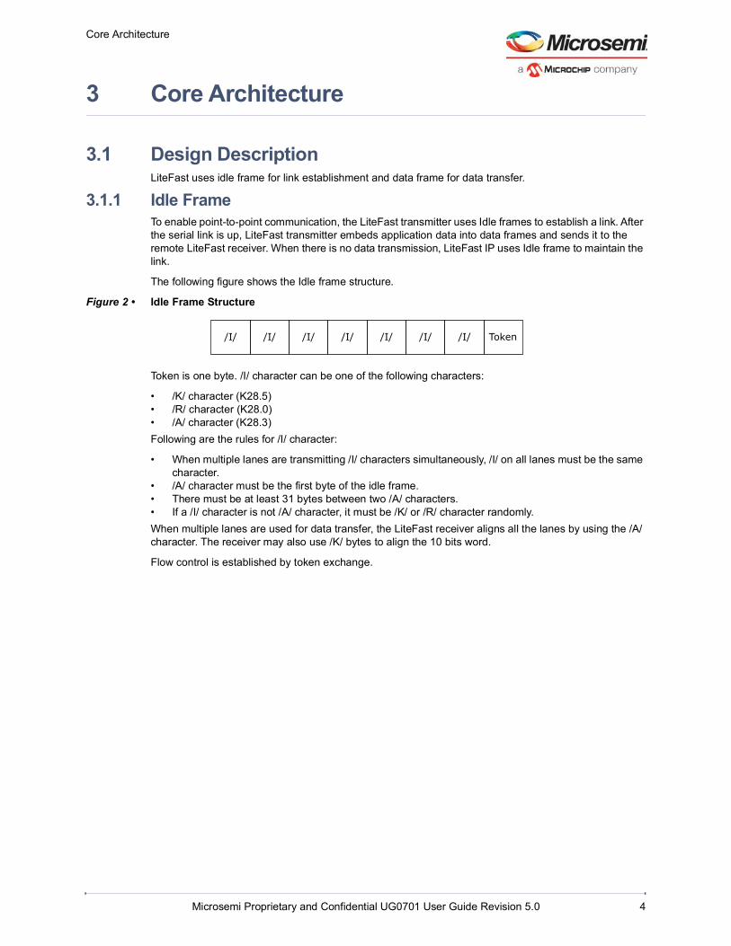
3.1.1 Idle FrameTo enable point-to-point communication, the LiteFast transmitter uses Idle frames to establish a link. After the serial link is up, LiteFast transmitter embeds application data into data frames and sends it to the remote LiteFast receiver. When there is no data transmission, LiteFast IP uses Idle frame to maintain the link.
The following figure shows the Idle frame structure.
Figure 2 • Idle Frame Structure
Token is one byte. /I/ character can be one of the following characters:
• /K/ character (K28.5)• /R/ character (K28.0)• /A/ character (K28.3)Following are the rules for /I/ character:
• When multiple lanes are transmitting /I/ characters simultaneously, /I/ on all lanes must be the same character.
• /A/ character must be the first byte of the idle frame.• There must be at least 31 bytes between two /A/ characters.• If a /I/ character is not /A/ character, it must be /K/ or /R/ character randomly.When multiple lanes are used for data transfer, the LiteFast receiver aligns all the lanes by using the /A/ character. The receiver may also use /K/ bytes to align the 10 bits word.
Flow control is established by token exchange.
/I/ /I/ /I/ /I/ Token/I/ /I/ /I/

Core Architecture
Microsemi Proprietary and Confidential UG0701 User Guide Revision 5.0 5
3.1.2 Data FrameApplication data is transmitted using data frames. The following figure shows the data frame structure.
Figure 3 • Data Frame Structure
Data frame fields include the following fields:
• Start of frame (SOF): Includes one K28.1 byte. The LiteFast receiver recognizes the header of the data frame by its SOF field.
• Data payload: Contains 1 to 128 bytes of application data. The length of the payload must be the multiple of 8, otherwise PAD (K28.4) bytes are filled to meet this requirement.
• End of frame (EOF): Includes one K28.7. LiteFast receiver recognizes the end of the data payload by EOF field.
• Reserved (Res): Reserved segment is 1-byte.• CRC-32 check sum: Contains the CRC-32 check sum for data payload. The polynomial is as shown
below
EQ1
• Token: It is one byte, which indicates the available buffer in the receive chain.
3.2 Flow ControlIn order to avoid a buffer overflow in receive chain, the local receiver communicates the available buffers to the local transmitter. Local transmitter communicates the same to the remote receiver through tokens. The remote LiteFast transmitter pauses data frame transmission when local receiver buffer is almost full, and the remote LiteFast transmitter resumes data frame transmission when the receiver buffer is not almost full.
The receiver buffer’s available storage space is encoded to token byte, which ranges from 0 to 255 bytes. Token is set to 1 when there are 0 to 127 available bytes in the receiver buffer. The token is set to two when there are 128 to 255 available bytes in the receiver buffer. The rule of token calculation is shown in the following equation.
EQ2
The token field indicates the number of bytes available in the remote receiver. The remote transmitter pauses data frame transmission, if the local receiver buffer is not able to store more than one data frame.
In Figure 4, page 6 System A and System B utilize SerDes and LiteFast to transfer data over a serial link.
In System A, the available storage space of the receiver buffer is encoded to a token byte. Token byte is provided to the LiteFast transmitter module and padded at the end of the data frame and idle frame.
In System B, LiteFast receiver receives the remote token from System A. The LiteFast transmitter determines whether it should send a LiteFast data frame according to the value of the remote token byte. System B also sends the local token byte to System A, the flow control mechanism is implemented by transferring token bytes on both sides.
SOF(1 byte)
EOF(1 byte)
Res(1 byte)
CRC-32 Checksum(4 bytes)
Token(1 byte)
Data Payload (1 to 128 bytes)
G x x32 x26 x23 x22 x16 x12 x11 x10 x8 x7 x5 x4 x2 x 1+ + + + + + + + + + + + + +=
Token IntRx Buffer available bytes128
----------------------------------------------------------------------------=

Core Architecture
Microsemi Proprietary and Confidential UG0701 User Guide Revision 5.0 6
The following figure shows the flow control mechanism.
Figure 4 • Token Byte Transfer
3.3 Multiple LanesIn multiple lanes, application data frame blocks are transmitted and received over multiple lanes:
• Data stream is cut into data blocks, each data block includes 8 bytes• Idle frame is one data blockThe following figure shows the stripping process for a four lane application.The data block is distributed on different lanes as blocks 0, 1, 2, 3. In this example, block 0 is placed on lane 3, block 1 on lane 2, block 2 on lane 1, and block 3 on lane 0.
System A
LiteFast Receiver
LiteFast Transmitter
User Logic
8b10b Coder
SerDesTx
8b10b Decoder
SerDesRx
Remote Token
Local Token
System B
LiteFast Receiver
LiteFast Transmitter
User Logic
8b10b Coder
SerDesTx
8b10b Decoder
SerDesRx
Remote Token
Local Token

Core Architecture
Microsemi Proprietary and Confidential UG0701 User Guide Revision 5.0 7
Figure 5 • Striping Process for Four Lane Application
In the LiteFast receiver, all lanes are aligned using /A/ characters, and the LiteFast data stream is recovered using a reversed stripping operation.
After the system is reset, LiteFast sends LiteFast idle frames to establish a link between the systems. The LiteFast receiver performs lane alignment using the Idle frames.
The data direction is from Fabric to SerDes.
/I/ /I/ /I/ /I/ /I/ /I/ /I/ /I/ /I/ /I/ /I/ /I/ /I/ /I/
D0 D1 D2 D3 D4 D5 D6 D7 D8 D9 D10 D11 D12 D13 PAD
PAD FSN CRC CRC CRC CRC /I/ /I/ /I/ /I/ /I/ /I/ /I/
/I/ /I/ /I/ /I/ /I/ /I/ /I/ /I/ /I/ /I/ /I/ /I/ /I/ /I/
/I/
/I/
/I/
/I/
/I/
/I/
/I/
Token
/I/
/I/
/I/
/I/
/I/
/I/
/I/
Token
/I/
/I/
/I/
/I/
/I/
/I/
/I/
Token
/I/
/I/
/I/
/I/
/I/
/I/
/I/
Token
K28.1
D0
D1
D2
D3
D4
D5
D6
D7
D8
D9
D10
D11
D12
D13
PAD
PAD
K28.7
FSN
CRC
CRC
CRC
CRC
Token
/I/
/I/
/I/
/I/
/I/
/I/
/I/
Token
Block 0 Block 1 Block 2 Block 3
Block 4 Block 5 Block 6 Block 7
Lane3 Lane2 Lane1 Lane0
Token
Token
Token
K28.1
K28.7
Token
Token
Token
Time
Byte 15 Byte 0Byte 7
Typical Application
Microsemi Proprietary and Confidential UG0701 User Guide Revision 5.0 8
4 Typical Application
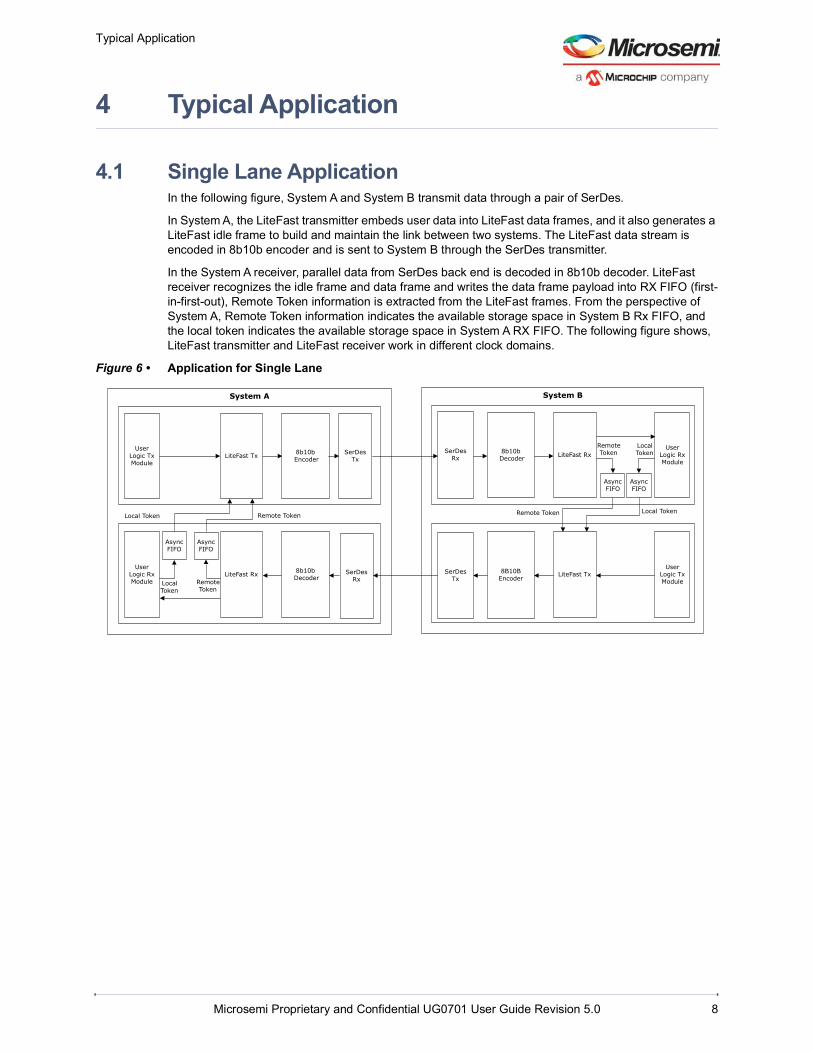
4.1 Single Lane ApplicationIn the following figure, System A and System B transmit data through a pair of SerDes.
In System A, the LiteFast transmitter embeds user data into LiteFast data frames, and it also generates a LiteFast idle frame to build and maintain the link between two systems. The LiteFast data stream is encoded in 8b10b encoder and is sent to System B through the SerDes transmitter.
In the System A receiver, parallel data from SerDes back end is decoded in 8b10b decoder. LiteFast receiver recognizes the idle frame and data frame and writes the data frame payload into RX FIFO (first-in-first-out), Remote Token information is extracted from the LiteFast frames. From the perspective of System A, Remote Token information indicates the available storage space in System B Rx FIFO, and the local token indicates the available storage space in System A RX FIFO. The following figure shows, LiteFast transmitter and LiteFast receiver work in different clock domains.
Figure 6 • Application for Single Lane
System BSystem A
LiteFast Tx 8b10b Encoder
SerDesTx
SerDesRx
8b10b Decoder LiteFast Rx
User Logic Rx Module
Async FIFO
Async FIFO
Remote Token
Local Token
LiteFast Tx8B10B Encoder
SerDesTx
Remote Token Local Token
SerDesRx
8b10b DecoderLiteFast Rx
User Logic Rx Module
Async FIFO
Async FIFO
Remote Token
Local Token
Remote TokenLocal Token
User Logic Tx Module
User Logic Tx Module
Typical Application
Microsemi Proprietary and Confidential UG0701 User Guide Revision 5.0 9
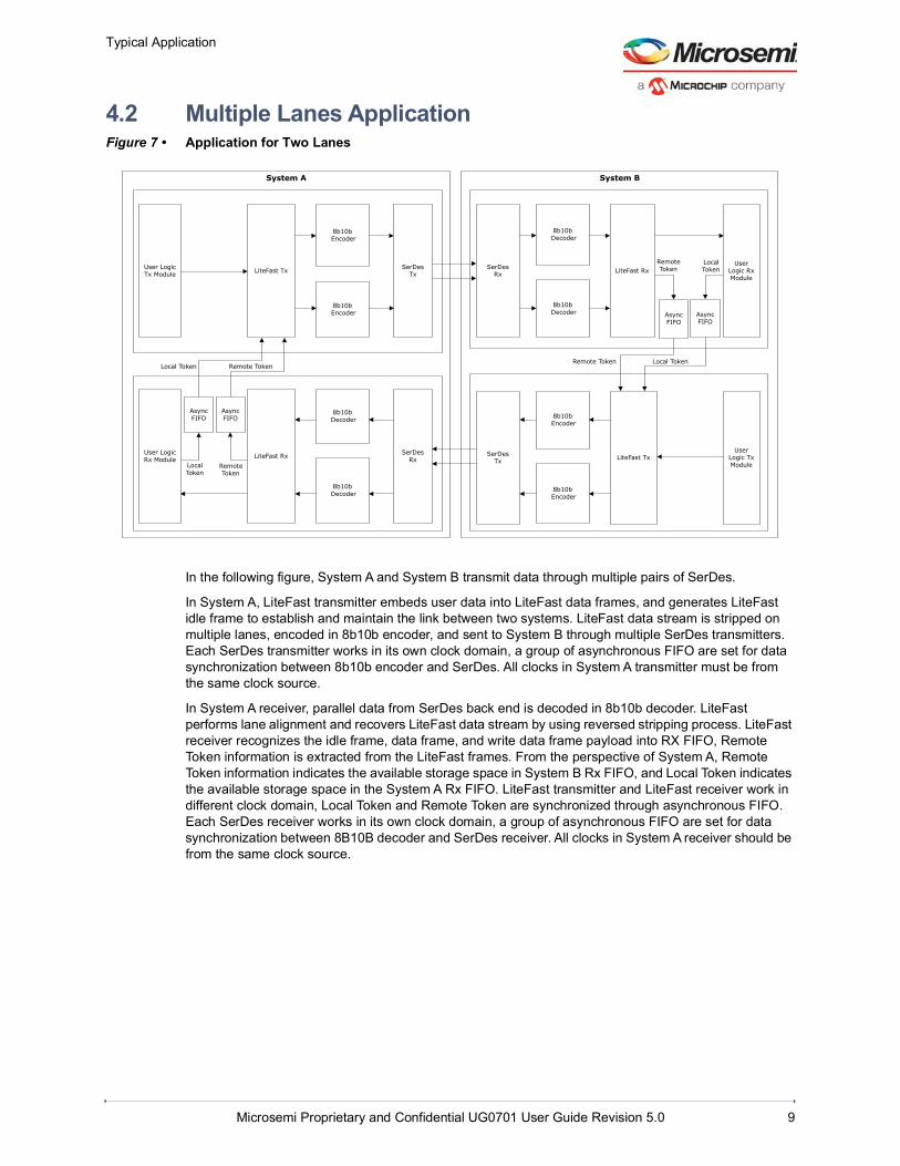
4.2 Multiple Lanes ApplicationFigure 7 • Application for Two Lanes
In the following figure, System A and System B transmit data through multiple pairs of SerDes.
In System A, LiteFast transmitter embeds user data into LiteFast data frames, and generates LiteFast idle frame to establish and maintain the link between two systems. LiteFast data stream is stripped on multiple lanes, encoded in 8b10b encoder, and sent to System B through multiple SerDes transmitters. Each SerDes transmitter works in its own clock domain, a group of asynchronous FIFO are set for data synchronization between 8b10b encoder and SerDes. All clocks in System A transmitter must be from the same clock source.
In System A receiver, parallel data from SerDes back end is decoded in 8b10b decoder. LiteFast performs lane alignment and recovers LiteFast data stream by using reversed stripping process. LiteFast receiver recognizes the idle frame, data frame, and write data frame payload into RX FIFO, Remote Token information is extracted from the LiteFast frames. From the perspective of System A, Remote Token information indicates the available storage space in System B Rx FIFO, and Local Token indicates the available storage space in the System A Rx FIFO. LiteFast transmitter and LiteFast receiver work in different clock domain, Local Token and Remote Token are synchronized through asynchronous FIFO. Each SerDes receiver works in its own clock domain, a group of asynchronous FIFO are set for data synchronization between 8B10B decoder and SerDes receiver. All clocks in System A receiver should be from the same clock source.
System BSystem A
LiteFast Tx
8b10b Encoder
8b10b Encoder
SerDesTx
SerDesRx
8b10b Decoder
8b10b Decoder
LiteFast RxUser
Logic Rx Module
Async FIFO
Async FIFO
Remote Token
Local Token
LiteFast Tx
8b10b Encoder
8b10b Encoder
SerDesTx
Remote Token Local Token
SerDesRx
8b10b Decoder
8b10b Decoder
LiteFast RxUser Logic Rx Module
Async FIFO
Async FIFO
Remote Token
Local Token
Remote TokenLocal Token
User Logic Tx Module
User Logic Tx Module
Typical Application
Microsemi Proprietary and Confidential UG0701 User Guide Revision 5.0 10
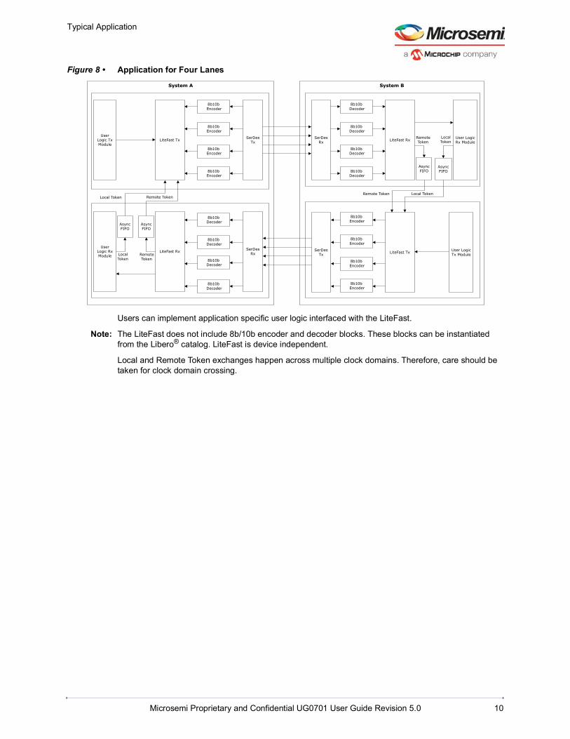
Figure 8 • Application for Four Lanes
Users can implement application specific user logic interfaced with the LiteFast.
Note: The LiteFast does not include 8b/10b encoder and decoder blocks. These blocks can be instantiated from the Libero® catalog. LiteFast is device independent.
Local and Remote Token exchanges happen across multiple clock domains. Therefore, care should be taken for clock domain crossing.
System BSystem A
LiteFast Tx
8b10b Encoder
8b10b Encoder
8b10b Encoder
8b10b Encoder
SerDesTx
SerDesRx
8b10b Decoder
8b10b Decoder
8b10b Decoder
8b10b Decoder
LiteFast Rx User Logic Rx Module
Async FIFO
Async FIFO
Local Token
LiteFast Tx
8b10b Encoder
8b10b Encoder
8b10b Encoder
8b10b Encoder
SerDesTx
Remote Token Local Token
SerDesRx
8b10b Decoder
8b10b Decoder
8b10b Decoder
8b10b Decoder
LiteFast RxUser
Logic Rx Module
Async FIFO
Remote Token
Local Token
Remote TokenLocal Token
Remote Token
Async FIFO
User Logic Tx Module
User Logic Tx Module

Interface Signals
Microsemi Proprietary and Confidential UG0701 User Guide Revision 5.0 11
5 Interface Signals
5.1 InterfaceLiteFast includes the LiteFast transmitter and LiteFast receiver. The following figure shows the block diagram of LiteFast interface signals.
Figure 9 • LiteFast Interface Signal
LiteFast
clk_tx_ireset_n_tx_i
local_rece_rdy_tx_i
simplex_en_i
usr_data_tx_i
min_remote_token_tx_i
req_usr_data_tx_o
litefast_k_tx_o
litefast_data_tx_o
clk_rx_ireset_n_rx_i
serdes_rx_val_i
lane_k_rx_i
lane_data_rx_i
block_aligned_rx_o
crc_err_rx_o
lane_aligned_rx_o
remote_token_rx_o
usr_data_val_rx_o
usr_data_rdy_tx_i
local_token_tx_i
remote_token_tx_i
crc_err_en_tx_i
word_aligned_rx_i
usr_data_rx_o
usr_data_val_tx_i

Interface Signals
Microsemi Proprietary and Confidential UG0701 User Guide Revision 5.0 12
5.2 Configuration ParametersThe following table lists the configuration parameters used in the hardware implementation process of LiteFast.
Note: Parameters are generic and vary based on the application requirements.
The following table lists the user application data width for LiteFast in SmartFusion2, IGLOO2, RTG4, and PolarFire devices.
Table 1 • Configuration Parameters1
1. 8-bit width is not supported with 8b10b mode in XCVR on PolarFire devices.
Name Descriptiong_DATA_WID LiteFast data bus width, it can be 8 bits, 16 bits, 32 bits, or 64 bits.
g_LANE_NUM Lane number. It can be 1, 2, or 4.When g_DATA_WID = 8, it must be 1.When g_DATA_WID = 16, it may be 1 or 2.When g_DATA_WID = 32, it may be 1, 2, or 4.When g_DATA_WID = 64, it may be 2 or 4.
Table 2 • User Application Data Width1
1. 8-bit width is not supported with 8b10b mode in XCVR on PolarFire devices.
User Application Data Width 1 Lane 2 Lanes 4 Lanes8 bits Support No No
16 bits Support maximum 16 bits in one lane
Support maximum 8 bits per lane
No
32 bits Support maximum 32 bits per lane
Support maximum 16 bits per lane
Support maximum 8 bits per lane
64 bits No Support maximum 32 bits per lane
Support maximum 16 bits per lane
Interface Signals
Microsemi Proprietary and Confidential UG0701 User Guide Revision 5.0 13
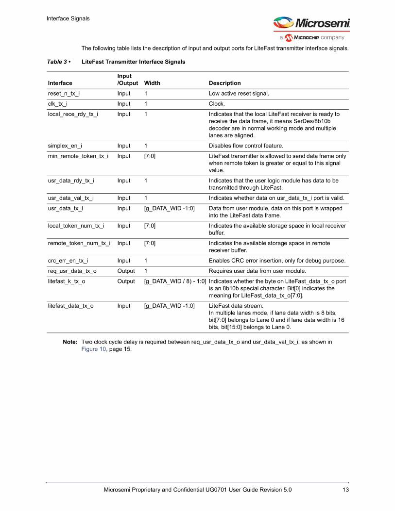
The following table lists the description of input and output ports for LiteFast transmitter interface signals.
Note: Two clock cycle delay is required between req_usr_data_tx_o and usr_data_val_tx_i, as shown in Figure 10, page 15.
Table 3 • LiteFast Transmitter Interface Signals
InterfaceInput/Output Width Description
reset_n_tx_i Input 1 Low active reset signal.
clk_tx_i Input 1 Clock.
local_rece_rdy_tx_i Input 1 Indicates that the local LiteFast receiver is ready to receive the data frame, it means SerDes/8b10b decoder are in normal working mode and multiple lanes are aligned.
simplex_en_i Input 1 Disables flow control feature.
min_remote_token_tx_i Input [7:0] LiteFast transmitter is allowed to send data frame only when remote token is greater or equal to this signal value.
usr_data_rdy_tx_i Input 1 Indicates that the user logic module has data to be transmitted through LiteFast.
usr_data_val_tx_i Input 1 Indicates whether data on usr_data_tx_i port is valid.
usr_data_tx_i Input [g_DATA_WID -1:0] Data from user module, data on this port is wrapped into the LiteFast data frame.
local_token_num_tx_i Input [7:0] Indicates the available storage space in local receiver buffer.
remote_token_num_tx_i Input [7:0] Indicates the available storage space in remote receiver buffer.
crc_err_en_tx_i Input 1 Enables CRC error insertion, only for debug purpose.
req_usr_data_tx_o Output 1 Requires user data from user module.
litefast_k_tx_o Output [g_DATA_WID / 8) - 1:0] Indicates whether the byte on LiteFast_data_tx_o port is an 8b10b special character. Bit[0] indicates the meaning for LiteFast_data_tx_o[7:0].
litefast_data_tx_o Input [g_DATA_WID -1:0] LiteFast data stream.In multiple lanes mode, if lane data width is 8 bits, bit[7:0] belongs to Lane 0 and if lane data width is 16 bits, bit[15:0] belongs to Lane 0.

Interface Signals
Microsemi Proprietary and Confidential UG0701 User Guide Revision 5.0 14
The following table lists the description of input and output ports for LiteFast receiver interface signals.
5.3 Key Interface Description5.3.1 local_rece_rdy_tx_i
The interface port local_rece_rdy_tx_i in the LiteFast transmitter must be connected with the local LiteFast receiver’s lane_algined_rx_o port.
Table 4 • LiteFast Receiver Interface Signals
InterfaceInput/Output Width Description
reset_n_rx_i Input 1 Low active reset signal.
clk_rx_i Input 1 Clock.
serdes_rx_val_i Input [g_LANE_NUM -1:0] Indicates whether SerDes receiver is ready for work.
word_aligned_rx_i Input [g_LANE_NUM -1:0] Indicates whether 8b10b decoder is ready for work.In multiple lanes mode, bit[0] indicates the status for Lane 0.
lane_k_rx_i Input [g_DATA_WID / 8) - 1:0] Indicates whether byte on lane_data_rx_i port is an 8b10b special character. Bit[0] indicates the meaning for lane_data_rx_i[7:0].
lane_data_rx_i Input [g_DATA_WID - 1:0] Input data stream.In multiple lanes mode, if lane data width is 8 bits, bit[7:0] belongs to Lane 0 and if lane data width is 16 bits, bit[15:0] belongs to Lane 0.
crc_err_rx_o Output 1 Indicates whether CRC error is received.
usr_data_val_rx_o Output 1 Indicates whether data on usr_data_rx_o port is valid.
usr_data_rx_o Output [g_DATA_WID -1:0] User data from the LiteFast data frame payload.
remote_token_rx_o Output [7:0] Remote token byte.
lane_aligned_rx_o Output 1 Indicates whether multiple lanes are aligned and whether SerDes and 8b10b decoder are working fine.
block_aligned_rx_o Output [g_LANE_NUM -1:0] Indicates whether each lane’s data block is aligned. It is only for debug purpose. Bit[0] indicates the status of Lane 0.

Interface Signals
Microsemi Proprietary and Confidential UG0701 User Guide Revision 5.0 15
5.3.2 min_remote_token_tx_iFor the purpose of flow control, LiteFast transmitter pauses data frame transmission when remote token is less than min_remote_token_tx_i. When setting the value of min_remote_token_tx_i, the maximal remote token transmission delay and maximal delay must be considered between the LiteFast transmitter and remote receiver buffer.
If user uses the integration design in typical application chapter, the transmission delay between SerDes receiver pin and SerDes transmitter pin is less than 10 ns. The following table lists the min_remote_token_tx_i setting details.
5.3.3 req_usr_data_tx_o and usr_data_tx_iLiteFast Transmitter requires data from the user logic module.
5.4 Timing DiagramThe following figure shows the timing operation of the LiteFast transmitter.
Figure 10 • Timing Diagram for LiteFast Transmitter
Table 5 • min_remote_token_tx_i settings
Data Width Lane Number min_remote_token_tx_ig_DATA_WID = 8 g_LANE_NUM = 1 3
g_DATA_WID = 16 g_LANE_NUM = 1 6
g_LANE_NUM = 2 6
g_DATA_WID = 32 g_LANE_NUM = 1 8
g_LANE_NUM = 2 8
g_LANE_NUM = 4 8
g_DATA_WID = 64 g_LANE_NUM = 2 16
g_LANE_NUM = 4 16
clk_tx_i
usr_data_rdy_tx_i
req_usr_data_tx_o
usr_data_val_tx_i
usr_data_tx_i D0 D1 D2 D3 D4 D5

Interface Signals
Microsemi Proprietary and Confidential UG0701 User Guide Revision 5.0 16
5.5 Resource UtilizationsThe following table lists the resource utilization of the LiteFast IP implemented in a RTG4 FPGA device.
The following table lists the resource utilization of the LiteFast IP implemented in the SmartFusion2 SoC FPGA device.
The following table lists the resource utilization of the LiteFast IP implemented in the PolarFire devices.
Note: The preceding utilization values must be used for approximate estimates only. Utilization varies in actual implementation.
Table 6 • Resource Utilization for RTG4 FPGAs
Working Mode 4LUT DFF RAM64x18 RAM1K188 bits x 1 lane 338 298 0 0
8 bits x 2 lane 1334 1168 2 0
8 bits x 4 lane 2377 2012 4 0
16 bits x 1 lane 531 393 0 0
16 bits x 2 lane 1675 1451 4 0
16 bits x 4 lane 2190 2535 8 0
Table 7 • Resource Utilization for SmartFusion2 SoC FPGAs
Working Mode SLE CFG RAM64x18 RAM1K188 bits x 1 Lane 300 310 0 0
8 bits x 2 Lanes 1060 1250 2 0
8 bits x 4 Lanes 1850 2300 4 0
16 bits x 1 Lane 380 480 0 0
16 bits x 2 Lanes 1260 1450 4 0
16 bits x 4 Lanes 2220 2540 8 0
Table 8 • Resource Utilization for PolarFire FPGAs
Working Mode SLE CFG µSRAM LSRAM16 bits x 1 Lane 393 515 0 0
16 bits x 2 Lanes 1313 1576 4 0
16 bits x 4 Lanes 2230 2464 8 0
32 bits x 1 Lane 502 820 0 0
32 bits x 2 Lanes 1659 1889 8 0