uk abwr generic design assessment - advanced …e06...form10/00 hitachi-ge nuclear energy, ltd. uk...
TRANSCRIPT

Form10/00
Hitachi-GE Nuclear Energy, Ltd.
UK ABWR
UK ABWR Generic Design Assessment
Approach to Sampling and Monitoring
Document ID : GA91-9901-0029-00001 Document Number : 3E-GD-K002 Revision Number : H
NOT PROTECTIVELY MARKED Form01/03
Page ii/ii
GA91-9901-0029-00001 Rev. H
NOT PROTECTIVELY MARKED
UK ABWR
DISCLAIMERS
Proprietary Information
This document contains proprietary information of Hitachi-GE Nuclear Energy, Ltd. (Hitachi-GE), its
suppliers and subcontractors. This document and the information it contains shall not, in whole or in part,
be used for any purpose other than for the Generic Design Assessment (GDA) of Hitachi-GE’s UK ABWR.
This notice shall be included on any complete or partial reproduction of this document or the information it
contains.
Copyright
No part of this document may be reproduced in any form, without the prior written permission of
Hitachi-GE Nuclear Energy, Ltd.
Copyright (C) 2017 Hitachi-GE Nuclear Energy, Ltd. All Rights Reserved.

NOT PROTECTIVELY MARKED Form05/01 UK ABWR Generic Environmental Permit
Revision H
Approach to Sampling and Monitoring: Table of Contents Ver.0 i
NOT PROTECTIVELY MARKED
Table of Contents
1. Acronyms ...................................................................................................... 1
2. References .................................................................................................... 3
3. Introduction ................................................................................................. 6
3.1 Objective........................................................................................................................... 6
3.2 Scope ................................................................................................................................. 6
4. Regulatory Context ..................................................................................... 8
4.1 P&ID Requirements ........................................................................................................ 8
4.2 Legislation ........................................................................................................................ 8
4.3 Standards ....................................................................................................................... 10
4.4 Guidance......................................................................................................................... 11
5. Parameters to be Measured (Final Discharge) ....................................... 13
5.1 Radionuclide .................................................................................................................. 13
5.2 Discharge Flow .............................................................................................................. 14
6. Safety Categorisation and Classification ................................................ 15
7. System and Equipment Design ................................................................ 16
7.1 GDA Submission Scope ................................................................................................ 16
7.2 Sampling and Monitoring Locations ........................................................................... 16
7.3 Gaseous Sampling.......................................................................................................... 19
7.4 Liquid Sampling ............................................................................................................ 22
7.5 Solid Waste and Non-aqueous Liquid Sampling ........................................................ 22
7.6 In-process Sampling and Monitoring (Gaseous Discharges) .................................... 23
7.7 In-process Sampling and Monitoring (Liquid Discharges) ....................................... 24
8. Demonstration of BAT .............................................................................. 25
8.1 Claim 1 – Verify that Radioactive Discharge to the Environment Complies with the Permit ....................................................................................................................... 25
8.2 Claim 2 – Provide Robust Data to Assess the Radiological Impacts to the Public and the Environment .................................................................................................... 27
8.3 Claim 3 – Minimise Radioactive Discharge to the Environment .............................. 43
9. Independent Sampling .............................................................................. 44
9.1 Gaseous Sampling.......................................................................................................... 54
9.2 Liquid Sampling ............................................................................................................ 54
10. Responsibilities for Future Licensee ........................................................ 56
11. Conclusions ................................................................................................ 57
Appendix A: Standards and Guidance Alignment Matrix ............................... 58

NOT PROTECTIVELY MARKED Form05/01 UK ABWR Generic Environmental Permit
Revision H
Approach to Sampling and Monitoring Ver.0 1
NOT PROTECTIVELY MARKED
1. Acronyms
ABWR Advanced Boiling Water Reactor
ALARP As Low As Reasonably Practicable
BAT Best Available Technique
BS British Standard
C&I Control and Instrumentation
C/B Control Building
CAD Controlled Area Drain System
CD Condensate Demineraliser System
CF Condensate Filter System
CST Condensate Storage Tank
CUW Reactor Water Clean-up System
D/W Drywell
DBF Design Basis Fault
EPR Environmental Permitting Regulations
EU European Union
FCVS Filtered Containment Venting System
GDA Generic Design Assessment
GDF Geological Disposal Facility
GEP Generic Environmental Permit
GEP-RSR Generic Environmental Permit – Radioactive Substances Regulation
HCW High Chemical Impurities Waste System
HEPA High Efficiency Particulate Air Filter
HF Human Factors
HFI Human Factors Integration
HMI Human-Machine Interface
HP High Pressure
HVAC Heating Ventilating and Air Conditioning System
ICP-MS Inductively Coupled Plasma – Mass Spectrometry
ILW Intermediate Level Waste
IPPC Integrated Pollution Prevention and Control
LCW Low Chemical Impurities Waste System
LD Laundry Drain System
LLW Low Level Waste
LLWR Low Level Waste Repository
LP Low Pressure
MCERTS Monitoring Certification Scheme
MCR Main Control Room
MVP Mechanical Vacuum Pump
NPP Nuclear Power Plant
OG Off-Gas System
NOT PROTECTIVELY MARKED Form05/01 UK ABWR Generic Environmental Permit
Revision H
Approach to Sampling and Monitoring Ver.0 2
NOT PROTECTIVELY MARKED
P&ID Process and Information Document for Generic Assessment of Candidate Nuclear Power Plant
Designs
PCSR Pre-Construction Safety Report
PCV Primary Containment Vessel
PST Power Suppression Test
R/A Reactor Area
R/B Reactor Building
REPs Radioactive Substances Regulation – Environmental Principles
RGP Relevant Good Practice
RPV Reactor Pressure Vessel
Rw/B Radwaste Building
S/B Service Building
SFIS Spent Fuel Interim Storage
SGTS Standby Gas Treatment System
SJAE Steam Jet Air Ejector
SWMS Solid Waste Management System
T/B Turbine Building
TGN Technical Guidance Note
TGS Turbine Gland Steam System
W/W Wetwell
NOT PROTECTIVELY MARKED Form05/01 UK ABWR Generic Environmental Permit
Revision H
Approach to Sampling and Monitoring Ver.0 3
NOT PROTECTIVELY MARKED
2. References
[Ref-1] Environment Agency, “Process and Information Document for Generic Assessment of Candidate
Nuclear Power Plant Designs”, Version 3, October 2016.
[Ref-2] Hitachi-GE Nuclear Energy, Ltd., “Generic PCSR Chapter 5 : General Design Aspects”, GA91-
9101-0101-05000, XE-GD-0645, Rev. C, August 2017.
[Ref-3] Hitachi-GE Nuclear Energy, Ltd., “Integrated Waste Strategy”, GA91-9201-0003-00425, WE-
GD-0050, Rev. 3, July 2017.
[Ref-4] Hitachi-GE Nuclear Energy, Ltd., “Radioactive Solid Wastes Monitoring Requirements”, GA91-
9201-0003-00629, WE-GD-0055, Rev. 1, March 2016.
[Ref-5] Hitachi-GE Nuclear Energy, Ltd., “Radioactive Waste Management Arrangements”, GA91-
9901-0022-00001, WE-GD-0001, Rev. H, August 2017.
[Ref-6] Hitachi-GE Nuclear Energy, Ltd., “Other Environmental Regulations”, GA91-9901-0027-00001,
XE-GD-0098, Rev. G, August 2017.
[Ref-7] Hitachi-GE Nuclear Energy, Ltd., “Demonstration of BAT”, GA91-9901-0023-00001, XE-GD-
0097, Rev. G, August 2017.
[Ref-8] Hitachi-GE Nuclear Energy, Ltd., “Generic PCSR Chapter 14 : Control and Instrumentation”,
GA91-9101-0101-14000, 3E-GD-A0063, Rev. C, August 2017.
[Ref-9] Hitachi-GE Nuclear Energy, Ltd., “Generic PCSR Chapter 27 : Human Factors”, GA91-9101-
0101-27000, HFE-GD-0057, Rev. C, August 2017.
[Ref-10] Hitachi-GE Nuclear Energy, Ltd., “Generic PCSR Chapter 21 : Human-Machine Interface”,
GA91-9101-0101-21000, 3E-GD-A0060, Rev. C, August 2017.
[Ref-11] The Stationery Office, “The Environmental Permitting (England and Wales) Regulations 2016
(SI 2016 No.1154)”, December 2016.
[Ref-12] OSPAR Commission, “Convention for the protection of the marine environment of the north-east
atrantic”, 2007.
[Ref-13] European Communities, “Council directive 96/61/EC of 24 September 1996 concerning
integrated pollution prevention and control”, 1996.
[Ref-14] Hitachi-GE Nuclear Energy, Ltd., “Approach to Optimisation”, GA91-9901-0021-00001, XE-
GD-0096, Rev. F, August 2017.
[Ref-15] Euratom, “Commission verification of facilities in Member States which carry out continuous
monitoring of levels of radioactivity in air, water and soil”, 2006.
[Ref-16] Euratom, “Directives laying down basic safety standards of protection against the dangers arising
from exposure to ionising radiation”, 2013 (2013/59/EURATOM).
[Ref-17] Euratom, “Commission recommendation of 18 December 2003 on standardised information on
radioactive airborne and liquid discharges into the environment from nuclear power reactors and
reprocessing plants in normal operation”, 2004 (2004/2/Euratom).

NOT PROTECTIVELY MARKED Form05/01 UK ABWR Generic Environmental Permit
Revision H
Approach to Sampling and Monitoring Ver.0 4
NOT PROTECTIVELY MARKED
[Ref-18] Euratom, “Corrigendum to Commission Recommendation 2004/2/Euratom of 18 December 2003
on standardised information on radioactive airborne and liquid discharges into the environment
from nuclear power reactors and reprocessing plants in normal operation”, 2004.
[Ref-19] British Standards Institution, “Sampling airborne radioactive materials from the stacks and ducts
of nuclear facilities”, BS ISO 2889:2010.
[Ref-20] The International Organization for Standardization, “Stationary source emissions – Measurement
of velocity and volume flow rate of gas streams in ducts”, ISO 10780:1994.
[Ref-21] British Standards Institution, “Equipment for continuous monitoring of radioactivity in gaseous
effluents – Part 1: General requirements”, BS EN 60761-1:2004.
[Ref-22] British Standards Institution, “Equipment for continuous monitoring of radioactivity in gaseous
effluents – Part 3: Specific requirements for radioactive noble gas monitors”, BS EN 60761-
3:2004.
[Ref-23] Environment Agency, “Performance Standard for Organisations Undertaking Radioanalytical
Testing of Environmental and Waste Waters”, Version 2, July 2015.
[Ref-24] British Standards Institution, “General requirements for the competence of testing and calibration
laboratories", BS EN ISO/IEC 17025:2005.
[Ref-25] Environment Agency, “Minimum Requirements for the Self-Monitoring of Flow”, Version 4.0,
August 2014.
[Ref-26] Environment Agency, “Performance Standards and Test Procedures for Continuous Emission
Monitoring Systems – For gaseous, particulate and flow-rate monitoring systems”, Version 3.5,
June 2016.
[Ref-27] Environment Agency, “Regulatory Guidance Series, No. RSR 1; Radioactive Substances
Regulation – Environmental Principles”, Version 2, April 2010.
[Ref-28] Hitachi-GE Nuclear Energy, Ltd., “Alignment with the Radioactive Substances Regulation
Environmental Principles (REPs)”, GA91-9901-0028-00001, XE-GD-0099, Rev. F, August 2017.
[Ref-29] Environment Agency, “Sampling requirements for stack emission monitoring”, Technical
Guidance Note (Monitoring) M1, Version 8, 2017.
[Ref-30] Environment Agency, “Monitoring of Radioactive Releases to Atmosphere from Nuclear
Facilities”, Technical Guidance Note (Monitoring) M11, 1999.
[Ref-31] Environment Agency, “Monitoring of Radioactive Releases to Water from Nuclear Facilities”,
Technical Guidance Note (Monitoring) M12, 1999.
[Ref-32] Hitachi-GE Nuclear Energy, Ltd., “Quantification of Discharges and Limits”, GA91-9901-0025-
00001, HE-GD-0004, Rev. G, August 2017.
[Ref-33] The International Organization for Standardization, “Nuclear energy – Vocabulary”, ISO
921:1997.
[Ref-34] International Atomic Energy Agency, “IAEA Safety Glossary – Terminology Used in Nuclear
Safety and Radiation Protection”, 2007 Edition.

NOT PROTECTIVELY MARKED Form05/01 UK ABWR Generic Environmental Permit
Revision H
Approach to Sampling and Monitoring Ver.0 5
NOT PROTECTIVELY MARKED
[Ref-35] Hitachi-GE Nuclear Energy, Ltd., “Demonstration of BAT for gaseous discharge system
argument 5a (Response to RQ-ABWR-0225)”, GA91-9201-0003-00350, HE-GD-0058, Rev. 0,
October 2014.
[Ref-36] Hitachi-GE Nuclear Energy, Ltd., “Prospective Dose Modelling”, GA91-9901-0026-00001, HE-
GD-0005, Rev. G, August 2017.
[Ref-37] Hitachi-GE Nuclear Energy, Ltd., “Human Factors Engineering Specification”, GA91-9201-
0001-00037, HFD-GD-0001, Rev. D, January 2017.
[Ref-38] Nuclear Safety Commission, “Guideline for measurement of radioactive materials released from
commercial light water reactor facilities”, March 2001.
[Ref-39] R. B. Firestone et al., “Table of Isotopes”, 8th edition, 1996.
[Ref-40] Sira Certification, MCERTS Certified Products: Continuous Water Monitoring System (CWMS)
Part 3 – Water Flowmeters, Issue 73, http://www.csagroupuk.org/wp-content/uploads/2017/02/M
CERTSCertifiedProductsCWMSPart3.pdf, (as of February 2017).
[Ref-41] Hitachi-GE Nuclear Energy, Ltd., “Generic PCSR Chapter 18 : Radioactive Waste Management”,
GA91-9101-0101-18000, XE-GD-0651, Rev. C, August 2017.
[Ref-42] Hitachi-GE Nuclear Energy, Ltd., “Generic PCSR Chapter 23 : Reactor Chemistry”, GA91-9101-
0101-23000, WPE-GD-0058, Rev. C, August 2017.
[Ref-43] J. Katakura, “JENDL FP Decay Data File 2011 and Fission Yields Data File 2011”, JAEA-
Data/Code 2011-025, March 2012.

NOT PROTECTIVELY MARKED Form05/01 UK ABWR Generic Environmental Permit
Revision H
Approach to Sampling and Monitoring Ver.0 6
NOT PROTECTIVELY MARKED
3. Introduction
3.1 Objective
The Environment Agency’s requirements for the provision of information in the Generic Design
Assessment (GDA) submission are defined within their Process and Information Document for Generic
Assessment of Candidate Nuclear Power Plant Designs (P&ID) [Ref-1]. This stipulates the necessary GDA
information requirements relating to sampling arrangements, as well as techniques and systems for
measurement and assessment of discharges and disposals of radioactive waste.
This submission provides the high level approach taken to determine the sampling and monitoring design
for the United Kingdom Advanced Boiling Water Reactor (UK ABWR) in response to the information
requests made in Item 6, Table 1 in [Ref-1].
3.2 Scope
The scope of this document is the sampling and monitoring of gaseous and aqueous radioactive wastes
during normal operation which covers all operating modes. [Ref-2] Table 3.2-1 summarises the scope of
the different documents that address sampling and monitoring in the GDA submission. In the GDA stage, it
is not possible to provide precise details on what sampling and monitoring equipment will be installed in
the UK ABWR, therefore the focus is on techniques rather than specific equipment.
The description of the sampling of solid radioactive wastes is an overview only, since the Solid Waste
Management System (SWMS) is only developed to a concept level during GDA. [Ref-3][Ref-4] The
management of non-aqueous radioactive wastes as well as solid radioactive wastes is described in the
Radioactive Waste Management Arrangements report [Ref-5]. The management of non-radioactive
discharges is described in Other Environmental Regulations report [Ref-6]. Information on non-radioactive
in-process monitoring is provided in the Demonstration of BAT report [Ref-7].
Other aspects of the GDA safety case design will influence the sampling and monitoring arrangements.
Details of Control and Instrumentation (C&I) such as architecture, plant computer system and software are
described in the PCSR Chapter 14 Control and Instrumentation [Ref-8] and its supporting documents. The
sampling and monitoring design to detect and monitor Design Basis Fault (DBF) is in the scope of the
PCSR Chapter 14. Some of the claims made in the Best Available Technique (BAT) case rely upon
evidence to demonstrate that claimed human actions are achievable and risks associated with human error
are As Low As Reasonably Practicable (ALARP). Human Factors (HF) considerations have, and will be,
incorporated in the design of each facility of the UK ABWR under the Human Factors Integration Plan.
Where HF are relied upon as part of the BAT case, these instances will be fed into the Human Factors
Integration (HFI) process outlined in the PCSR Chapter 27 Human Factors [Ref-9]. In addition, Human-
Machine Interface (HMI), especially in the control room, is included in the PCSR Chapter 21 Human-
Machine Interface [Ref-10].

NOT PROTECTIVELY MARKED Form05/01 UK ABWR Generic Environmental Permit
Revision H
Approach to Sampling and Monitoring Ver.0 7
NOT PROTECTIVELY MARKED
The sampling and monitoring is a fundamental function as long as radioactive wastes are being discharged
or disposed of. In some instances where it falls to the responsibility of the future licensee or it forecloses
future options at this stage, detailed information will be developed during the site specific stage. An
environmental monitoring programme is not included within the GDA submission due to the site specific
nature of the programme that will need to be developed as part of the site specific permitting application.
Environmental monitoring regimes vary from site to site and needs to be developed to reflect local
conditions such as local habits, local flora and fauna, dispersion and the plant conditions of the site. A
monitoring programme during decommissioning stage is also not included since this will be designed many
years down the line.
Table 3.2-1 Document Scope
Subject Sampling Point Document
Gaseous waste
Radioactive Final discharge In-process
This document
Non-radioactive (Combustion installation)
Final discharge [Ref-6]
Aqueous waste
Radioactive Final discharge In-process
This document
Non-radioactive Final discharge [Ref-6]
Non-aqueous waste Radioactive Disposal [Ref-5]
Solid waste Radioactive Disposal In-process
[Ref-4]
Demonstration of BAT – This document and [Ref-7]

NOT PROTECTIVELY MARKED Form05/01 UK ABWR Generic Environmental Permit
Revision H
Approach to Sampling and Monitoring Ver.0 8
NOT PROTECTIVELY MARKED
4. Regulatory Context
A number of regulatory requirements and forms of guidance exist that relate to the sampling and
monitoring of radioactive discharges as well as in-process monitoring. These have been outlined below,
with the main focus of each described. In Appendix A, a standards and guidance alignment matrix has been
provided which outlines how the UK ABWR fulfils the requirements with the various guidance documents.
4.1 P&ID Requirements
The Environment Agency has identified the information it requires to carry out its determination of the
GDA process in their P&ID [Ref-1]. The P&ID requirements relating to sampling arrangements, techniques
and systems for measurement and assessment of discharges and disposals of radioactive waste are
stipulated in Item 6, Table 1 in [Ref-1] as reproduced below:
‘A description of the sampling arrangements, techniques and systems for measurement and assessment of discharges and disposals of radioactive waste.
Include:
• details of in-process monitoring arrangements
• details of arrangements for monitoring final discharges of gaseous and aqueous wastes
• details of arrangements for monitoring disposals of non-aqueous liquid and solid wastes
• a demonstration that the proposals represent the best available techniques for monitoring
• confirmation that the sensitivity is sufficient to: - readily demonstrate compliance with the proposed limits - meet the levels of detection specified in reference EU, 2004
• a description of the facilities provided for independent periodic sampling (by the regulator) of final discharges of gaseous and aqueous wastes’
4.2 Legislation
The main legislative requirements relevant to this section of the P&ID are the Environmental Permitting
Regulations (EPR) 2010. Since the publication of the P&ID there has been an update to the EPR, now 2016.
[Ref-11] Note that these updates are mainly focused an incoperating the various ammendments and thus
has no impact on sampling and monitoring requirements.
A further requirement on sites with an EPR permit in England and Wales is that BAT is used for
monitoring discharges. The concept of BAT is defined in the OSPAR Convention [Ref-12] and in Directive
1996/61/EC on Integrated Pollution Prevention and Control (IPPC) [Ref-13]. Further information on
Hitachi-GE’s approach to assessing and demonstrating BAT is provided in the Approach to Optimisation
and Demonstration of BAT reports [Ref-14][Ref-7].

NOT PROTECTIVELY MARKED Form05/01 UK ABWR Generic Environmental Permit
Revision H
Approach to Sampling and Monitoring Ver.0 9
NOT PROTECTIVELY MARKED
Additionally, Article 35 of the Euratom Treaty [Ref-15] requires not only self-monitoring of the levels of
radioactivity in nuclear facilities but also the independent verification of the operation and efficiency of that
monitoring from competent authorities e.g. the Environment Agency or Natural Resources Wales.
4.2.1 EU 2004
The European Basic Safety Standards [Ref-16] references EU 2004 [Ref-17][Ref-18] and provides
recommendations on the standardised information on radioactive gaseous and liquid discharges to the
environment from nuclear power reactors and reprocessing plants in normal operations. Within the
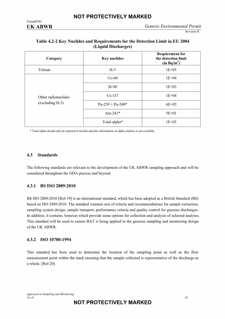
recommendations, a number of key nuclides and requirements for their detection limits are listed; these are
reproduced in Table 4.2-1 and Table 4.2-2.
Table 4.2-1 Key Nuclides and Requirements for the Detection Limit in EU 2004 (Gaseous Discharges)
Category Key nuclides Requirement for
the detection limit (in Bq/m3)
Noble gases Kr-85 1E+04*
Particulates
(excluding iodines)
Co-60 1E–02
Sr-90 2E–02
Cs-137 3E–02
Pu-239 + Pu-240** 5E–03
Am-241** 5E–03
Total-alpha** 1E–02
Iodines I-131 2E–02
Tritium H-3 1E+03
Carbon-14 C-14 1E+01
* Can normally be obtained by beta-measurement after decay of short-lived isotopes.
**Total-alpha should only be reported if nuclide-specific information on alpha-emitters is not available.
NOT PROTECTIVELY MARKED Form05/01 UK ABWR Generic Environmental Permit
Revision H
Approach to Sampling and Monitoring Ver.0 10
NOT PROTECTIVELY MARKED
Table 4.2-2 Key Nuclides and Requirements for the Detection Limit in EU 2004 (Liquid Discharges)
Category Key nuclides Requirement for
the detection limit (in Bq/m3)
Tritium H-3 1E+05
Other radionuclides
(excluding H-3)
Co-60 1E+04
Sr-90 1E+03
Cs-137 1E+04
Pu-239 + Pu-240* 6E+03
Am-241* 5E+01
Total-alpha* 1E+03
* Total-alpha should only be reported if nuclide-specific information on alpha-emitters is not available.
4.3 Standards
The following standards are relevant to the development of the UK ABWR sampling approach and will be
considered throughout the GDA process and beyond.
4.3.1 BS ISO 2889:2010
BS ISO 2889:2010 [Ref-19] is an international standard, which has been adopted as a British Standard (BS)
based on ISO 2889:2010. The standard contains sets of criteria and recommendations for sample extraction,
sampling system design, sample transport, performance criteria and quality control for gaseous discharges.
In addition, it contains Annexes which provide some options for collection and analysis of selected analytes.
This standard will be used to ensure BAT is being applied to the gaseous sampling and monitoring design
of the UK ABWR.
4.3.2 ISO 10780:1994
This standard has been used to determine the location of the sampling point as well as the flow
measurement point within the stack ensuring that the sample collected is representative of the discharge as
a whole. [Ref-20]
NOT PROTECTIVELY MARKED Form05/01 UK ABWR Generic Environmental Permit
Revision H
Approach to Sampling and Monitoring Ver.0 11
NOT PROTECTIVELY MARKED
4.3.3 BS EN 60761-1:2004 and BS EN 60761-3:2004
BS EN 60761:2004 series are international standards, which have been adopted as a BS based on IEC
60761:2002. BS EN 60761 focuses on equipment for the continuous monitoring of activity in gaseous
effluents. Part 1 [Ref-21] focuses on the general requirements of continuous monitoring, of which there is
some overlap with BS ISO 2889 [Ref-19]. The remainder of the series within this standard goes into detail
for specific analytes. Within the UK ABWR, only noble gases will be monitored continuously (as described
in Section 7.3.4), which is covered in Part 3 [Ref-22].
4.3.4 MCERTS
MCERTS is the Environment Agency’s Monitoring Certification Scheme. Its purpose is to promote the
production of quality monitoring data and provide the key foundation of licensee’s self-monitoring policy.
At present, for the analysis of radioactive discharges, only the analysis of liquid effluent is currently
covered by MCERTS [Ref-23]. This is in addition to the requirement of any analysis being conducted to
the BS EN ISO/IEC 17025:2005 [Ref-24]. There is also a requirement for flow measurements (for both
gaseous and liquid discharges) to be undertaken to MCERTS standard [Ref-25][Ref-26]. Flow
measurements are required to enable accurate accounting of the discharges as they are released to the
environment.
4.4 Guidance
The following guidance documents are relevant to the development of the UK ABWR sampling approach
and will be considered throughout the GDA process and beyond.
4.4.1 REPs
The sampling and monitoring arrangements that will be presented in this report will be consistent with
industry Relevant Good Practice (RGP) and take into account the relevant Radioactive Substances
Regulation – Environmental Principles (REPs) [Ref-27]. Hitachi-GE’s Alignment with the Radioactive
Substances Regulation Environmental Principles report [Ref-28] details the approach undertaken by
Hitachi-GE to reviewing and showing alignment with the relevant REPs within the GDA submission,
highlighting the REPs specifically addressed within each report.
The REPs considered most relevant to sampling and monitoring, as far as is covered in the scope of this
GDA report, are: RSMDP9, RSMDP13 and RSMDP14, as well as ENDP4, ENDP10 and ENDP14.
NOT PROTECTIVELY MARKED Form05/01 UK ABWR Generic Environmental Permit
Revision H
Approach to Sampling and Monitoring Ver.0 12
NOT PROTECTIVELY MARKED
4.4.2 TGN
The Environment Agency has produced a number of Technical Guidance Notes (TGNs) that are relevant to
sampling and monitoring. The main ones pertinent to the sampling and monitoring strategy are M1 [Ref-
29], M11 [Ref-30] and M12 [Ref-31].
M1 focuses on the generic stack monitoring and will provide the appropriate guidance for the location of
the sampling point within the vent stack in conjunction with ISO 10780 [Ref-20]. M11 then focuses on the
specific requirements for monitoring and sampling gaseous emissions from a nuclear facility. M12 relates
to the monitoring of radioactive releases to water from nuclear facilities and will be the main guide for the
UK ABWR’s liquid discharges.
NOT PROTECTIVELY MARKED Form05/01 UK ABWR Generic Environmental Permit
Revision H
Approach to Sampling and Monitoring Ver.0 13
NOT PROTECTIVELY MARKED
5. Parameters to be Measured (Final Discharge)
5.1 Radionuclide
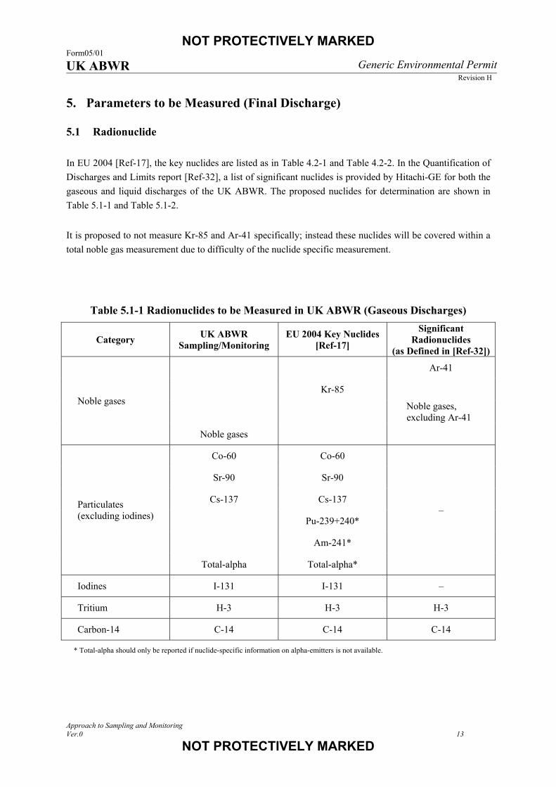
In EU 2004 [Ref-17], the key nuclides are listed as in Table 4.2-1 and Table 4.2-2. In the Quantification of
Discharges and Limits report [Ref-32], a list of significant nuclides is provided by Hitachi-GE for both the
gaseous and liquid discharges of the UK ABWR. The proposed nuclides for determination are shown in
Table 5.1-1 and Table 5.1-2.
It is proposed to not measure Kr-85 and Ar-41 specifically; instead these nuclides will be covered within a
total noble gas measurement due to difficulty of the nuclide specific measurement.
Table 5.1-1 Radionuclides to be Measured in UK ABWR (Gaseous Discharges)
Category UK ABWR
Sampling/Monitoring EU 2004 Key Nuclides
[Ref-17]
Significant Radionuclides
(as Defined in [Ref-32])
Noble gases
Ar-41
Kr-85
Noble gases, excluding Ar-41
Noble gases
Particulates (excluding iodines)
Co-60 Co-60
–
Sr-90 Sr-90
Cs-137 Cs-137
Pu-239+240*
Am-241*
Total-alpha Total-alpha*
Iodines I-131 I-131 –
Tritium H-3 H-3 H-3
Carbon-14 C-14 C-14 C-14
* Total-alpha should only be reported if nuclide-specific information on alpha-emitters is not available.

NOT PROTECTIVELY MARKED Form05/01 UK ABWR Generic Environmental Permit
Revision H
Approach to Sampling and Monitoring Ver.0 14
NOT PROTECTIVELY MARKED
Table 5.1-2 Radionuclides to be Measured in UK ABWR (Liquid Discharges)
Category UK ABWR
Sampling/Monitoring EU 2004 Key Nuclides
[Ref-17]
Significant Radionuclides
(as Defined in [Ref-32])
Tritium H-3 H-3 H-3
Other radionuclides (excluding H-3)
Co-60 Co-60
–
Sr-90 Sr-90
Cs-137 Cs-137
Pu-239+240*
Am-241*
Total-alpha Total-alpha*
* Total-alpha should only be reported if nuclide-specific information on alpha-emitters is not available.
5.2 Discharge Flow
To be able to report accurately the discharge of radioactive material from release points, the volumetric
flow of both gaseous and liquid effluent streams need to be continuously measured using an appropriate
MCERTS accredited technique. [Ref-25][Ref-26]

NOT PROTECTIVELY MARKED Form05/01 UK ABWR Generic Environmental Permit
Revision H
Approach to Sampling and Monitoring Ver.0 15
NOT PROTECTIVELY MARKED
6. Safety Categorisation and Classification
UK ABWR safety categorisation and classification is defined in the PCSR Chapter 5 General Design
Aspects [Ref-2]. The sampling system, as well as the continuous monitoring system, provides essential
information for determining radiological risk and supports plant operations to demonstrate they are ALARP.
Therefore the system is categorised and classified as Safety Category C and Class 3.
NOT PROTECTIVELY MARKED Form05/01 UK ABWR Generic Environmental Permit
Revision H
Approach to Sampling and Monitoring Ver.0 16
NOT PROTECTIVELY MARKED
7. System and Equipment Design
7.1 GDA Submission Scope
It is not deemed appropriate to provide details of the precise sampling and monitoring equipment in the
GDA stage, as technological development progresses at pace and Hitachi-GE would not be applying BAT
at the time of procurement if the equipment to be used is stated at this stage. Nevertheless, current methods
and techniques that are suitable to achieve the appropriate detection limit for each nuclide listed in Table
4.2-1 and Table 4.2-2 are described in Section 8.2.2, in order to demonstrate that the necessary performance
can be achieved.
7.2 Sampling and Monitoring Locations
The final discharge points have been identified to ensure an accurate record of discharge to the
environment can be made. Two locations within the design have currently been identified: one for gaseous
and one for liquid discharges as shown in Figure 7.2-1 and Figure 7.2-2, respectively. Both final sampling
locations are downstream of any abatement systems and hence provide an accurate record of what is
discharged to the environment.
The point for gaseous discharge is through the main stack, located on the top of the Reactor Building (R/B).
The main stack accepts gaseous effluent from the Heating Ventilating and Air Conditioning System
(HVAC) line and the Off-Gas System (OG) line which includes the Turbine Gland Steam System (TGS)
line.
The aqueous radioactive waste is treated in four subsystems. Three of four subsystems, namely High
Chemical Impurities Waste System (HCW), Laundry Drain System (LD) and Controlled Area Drain
System (CAD) are connected to the one final discharge line.
In addition to the discharge points there are a number of locations within the plant where in-process
monitoring and sampling occur. The selection of the locations of these is expanded upon within Sections
7.6 and 7.7. These, along with the final discharge points are shown in Figure 7.2-1 and Figure 7.2-2.
It should be noted that Figure 7.2-1 and Figure 7.2-2 illustrate the sampling and monitoring points
important in the assessment of environmental impact during radioactive effluent releases. In the UK
ABWR, further points are provided for detection and monitoring of the DBF. One example is the Standby
Gas Treatment System (SGTS). This is operated under fault conditions, and therefore the sampling and
monitoring arrangements on the SGTS line are out of scope of the Generic Environmental Permit (GEP)
application and submitted in the PCSR (Chapter 14 [Ref-8] and its supporting documents).

NOT PROTECTIVELY MARKED Form05/01 UK ABWR Generic Environmental Permit
Revision H
Approach to Sampling and Monitoring Ver.0 17
NOT PROTECTIVELY MARKED
Figure 7.2-1 Overview of Gaseous Discharges
SGTS (*2)
OGcondenser
Gland steam evaporator
OG recombiner
OG cooler condenser
OG charcoaladsorber (four towers)
Gland steam exhauster
MVPMain condenser
LP turbine
HP turbine
Gland steam condenser
T/B HVACR/A HVAC ~
~
~
OG ejector
D/W
RPV
SJAE
Main stack
Rw/B HVAC~
W/W
I
A
B
C
D
FG
H
F
Driving air
Ind
F
F
E
OG filter
PCV
TGS filter
CM
GS
Note
1. The information in this figure is restricted within radioactive discharge sampling and monitoring under the normal operation.
2. SGTS is operated under the fault condition and therefore out of scope of GEP-RSR.
Legend Flow meter Continuous monitoring point Grab sampling point Independent sampling point
The symbol shows monitoring or sampling point. It does not mean a piping branch.
Ind
F
CM
GS
GSCM F
GS CM F
GS CM
NOT PROTECTIVELY MARKED Form05/01 UK ABWR Generic Environmental Permit
Revision H
Approach to Sampling and Monitoring Ver.0 18
NOT PROTECTIVELY MARKED
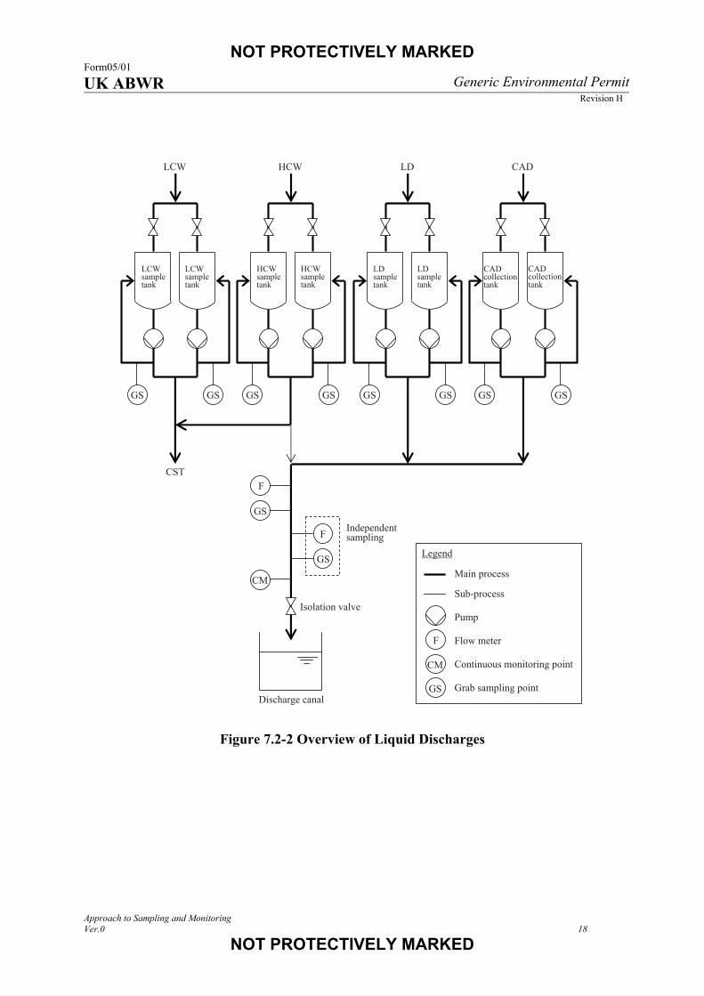
Figure 7.2-2 Overview of Liquid Discharges
LDsample tank
LDsample tank
LD
HCW sample tank
HCWsample tank
HCW
CAD collection tank
CAD
Discharge canal
LCW sample tank
LCW sample tank
LCW
CST
Independentsampling
Isolation valve
CADcollection tank
Legend
Main process Sub-process Pump Flow meter Continuous monitoring point Grab sampling point GS
CM
GS GS GSGS GSGS GSGS
GS
GS
F
F
CM
F
NOT PROTECTIVELY MARKED Form05/01 UK ABWR Generic Environmental Permit
Revision H
Approach to Sampling and Monitoring Ver.0 19
NOT PROTECTIVELY MARKED
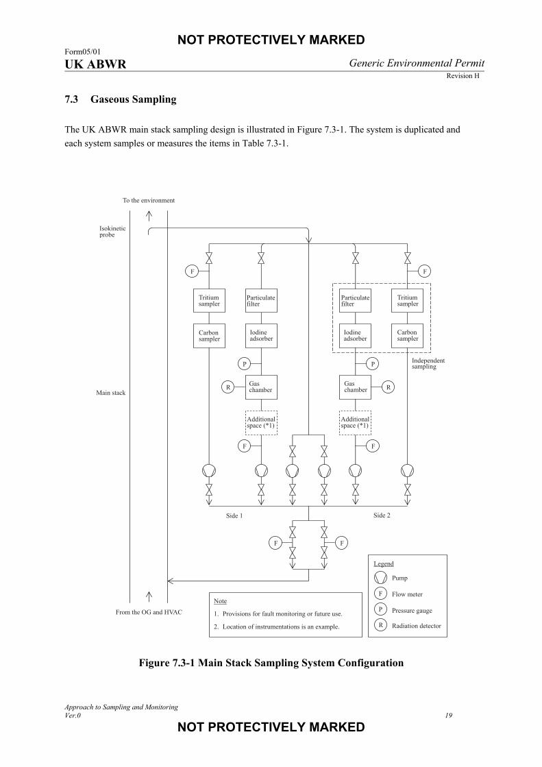
7.3 Gaseous Sampling
The UK ABWR main stack sampling design is illustrated in Figure 7.3-1. The system is duplicated and
each system samples or measures the items in Table 7.3-1.
Figure 7.3-1 Main Stack Sampling System Configuration
Main stack
Independentsampling
Isokinetic probe
R
P
F
P
F
FF
R
Note 1. Provisions for fault monitoring or future use.
2. Location of instrumentations is an example.
Pump
Flow meter
Pressure gauge
Radiation detector
Legend
F
P
R
Iodine adsorber
Particulate filter
Carbonsampler
Particulatefilter
Iodineadsorber
Tritium sampler
Tritiumsampler
Gas chamber
Gaschamber
Additionalspace (*1)
Additional space (*1)
F F
Carbon sampler
From the OG and HVAC
To the environment
Side 1 Side 2

NOT PROTECTIVELY MARKED Form05/01 UK ABWR Generic Environmental Permit
Revision H
Approach to Sampling and Monitoring Ver.0 20
NOT PROTECTIVELY MARKED
Table 7.3-1 Samples to be Collected and Analysed (Gaseous Discharges)
Sample Sampling Sample Collection Frequency
and Analysis
Particulates Continuous Periodic laboratory analysis
Iodines Continuous Periodic laboratory analysis
Noble gases Continuous Continuous monitoring
Tritium Continuous Periodic laboratory analysis
Carbon-14 Continuous Periodic laboratory analysis
Both sampling and monitoring systems will be running at all times. If the sampling period is set at two
weeks, then each system will be offset in turns of the sample change, e.g. Side 1 will sample weeks 1 and 2
and side 2 will sample weeks 2 and 3 and so on as shown in Figure 7.3-2. A representative sample is
continuously extracted from the main stack through an isokinetic probe. The sample passes through filters
or adsorbers in a dedicated sampling equipment room and is then returned to the main stack. The isokinetic
probe, sampling pipe, and return pipe are common for both systems. Note that locations of instruments
depend on final equipment selection and therefore are examples only at this stage in Figure 7.3-1. The
demonstration of BAT for this arrangement is described in Section 8.
The sample collection time will either be recorded by the instruments in the case of continuous monitoring,
or for sampling, a recording system will be developed by the future licensee and will form part of the data
quality arrangements.
Figure 7.3-2 Example of Sampling Period for Gaseous Discharges
Side 1
Side 2
Time
Sampling period (example)
Reporting period (example)
Week 1 Week 2 Week 3 Week 4 Week 5 Week 6
NOT PROTECTIVELY MARKED Form05/01 UK ABWR Generic Environmental Permit
Revision H
Approach to Sampling and Monitoring Ver.0 21
NOT PROTECTIVELY MARKED
7.3.1 Discharge Flow
Volumetric flow is monitored at the sampling point within the stack. The exact number and locations of
flow measurement will be determined during commissioning. It is expected that instruments such as pitot
tubes will be used for this purpose.
7.3.2 Particulates
Particulate material will be collected on appropriate filter media for laboratory analysis.
7.3.3 Iodines
In addition to any particulate iodine, other chemical forms of iodine will be collected using an appropriate
solid adsorbent material. This is expected to be in the form of a charcoal filter arrangement.
7.3.4 Noble Gases
Noble gases will be continuously monitored by the use of a fixed volume calibrated chamber and
appropriate detector system(s). The gas will be collected and analysed after the removal of any potential
particulate material and iodine have been collected for separate analysis. [Ref-22]
The radiation detector assembly will consist of a shielded gas chamber that houses a detector. A checking
source is contained as necessary. A radiation monitoring unit in the Main Control Room (MCR) processes
and visually displays the measured radiation level. If the system detects a high radiation level, it activates
an alarm in the MCR to warn operating personnel.
The gas chamber is purged with ambient air when a background level measurement is made.
7.3.5 Tritium and Carbon-14
It is proposed to use a series of bubblers to collect samples for analysis by an appropriate analytical
technique for the determination of tritium and carbon-14. The sample collection system will be made of a
series of bubble traps (number to be determined by the future licensee) to prevent any loss of sample
through the first trap. The exact composition of the bubbler solutions will be determined by the future
licensee to ensure that BAT is being applied.

NOT PROTECTIVELY MARKED Form05/01 UK ABWR Generic Environmental Permit
Revision H
Approach to Sampling and Monitoring Ver.0 22
NOT PROTECTIVELY MARKED
7.3.6 Sampling Flow
Volumetric flow is measured for each sampling line to calculate activity concentration 1 for each
radionuclide. Total sampling flow is also measured and controlled as constant to keep an isokinetic
sampling condition.
7.4 Liquid Sampling
The liquid discharge line is shown in Figure 7.2-2. It comprises of four subsystems; three of the four
subsystems are connected to the one final discharge line, with each subsystem having two storage tanks.
Once a storage tank within a subsystem is full, then it is sealed from additional input and a sample collected
once the recirculation line has agitated that tank. This sample is analysed prior to allowing the liquid to be
discharged into the discharge canal. This is not final sentencing analyses.
Samples are collected from the final discharge line exiting the discharge tank using a flow proportional
sampler to give an accurate record of what is finally discharged. At the sample location the flow of the
discharge is also measured. Redundancy for discharge sampling has been provided in the form of duplicate
flow measurement apparatus along with a second flow proportional sampler.
In addition to the sample collection, a continuous radiation monitor is provided in the liquid discharge line,
if the system detects a high radiation level, it activates an alarm and closes an isolation valve to stop the
discharge to the environment.
7.5 Solid Waste and Non-aqueous Liquid Sampling
The SWMS will be designed to receive, sort and process/condition all solid waste and wet solid Low Level
Waste (LLW) and Intermediate Level Waste (ILW) streams resulting from UK ABWR operation.
Following processing and conditioning, LLW is dispatched off-site for either incineration, recycling (in the
case of recyclable metals), or direct disposal to the Low Level Waste Repository (LLWR) site, while ILW
is transferred for interim storage (pending availability of the Geological Disposal Facility (GDF)) in an on-
site shielded ILW store.
The solid radwaste is monitored at each stage to maintain traceability and assure the SWMS performance.
Prior to dispatch for final disposal, the sample is analysed in order to ensure compliance with the regulatory
permit.
Non-aqueous liquid wastes will be sampled as close to the generation point as possible and a sample sent to
an appropriate laboratory for characterisation. Once it is recognised as radioactive, sampling and
monitoring will be carried out prior to the treatment and/or disposal by a specialist contractor.
1 The “activity concentration” is the activity per unit volume in this document as defined in ISO 921 [Ref-33] and noted in IAEA glossary [Ref-34].

NOT PROTECTIVELY MARKED Form05/01 UK ABWR Generic Environmental Permit
Revision H
Approach to Sampling and Monitoring Ver.0 23
NOT PROTECTIVELY MARKED
7.6 In-process Sampling and Monitoring (Gaseous Discharges)
7.6.1 Sampling and Monitoring Locations
The radiation levels of the off-gas and TGS off-gas are continuously monitored before they feed to the
main stack as shown in Figure 7.2-1. To enable nuclide analyses, grab sampling provisions are provided.
The radiation level of the HVAC exhaust is not continuously monitored (described in Section 8.3.3). The
flow rate of each line is continuously measured to monitor the performance of each system.
7.6.2 Off-gas
During radioactive effluent releases, the major gaseous radioactive waste is contained within the off-gas
which includes the fission-produced noble gases. The effluent is treated in the OG where noble gases are
held up on charcoal adsorbers to reduce the activity before discharge to the environment. In the UK ABWR,
the inlet and outlet of the OG charcoal adsorber are monitored.
At the inlet of the OG charcoal adsorber, a radiation detector continuously measures the gross radiation
level of the pre-treated off-gas which represents to the amount of the noble gas transported from the reactor.
The measured radiation level is displayed and recorded in the MCR. If the system detects a high radiation
level, it activates an alarm in the MCR. A grab sampling provision also enables detailed analysis to obtain
the radionuclide composition. A flow meter is provided to monitor the operating status of the OG. The
measured flow rate is displayed and recorded in the MCR.
At the outlet of the OG charcoal adsorber, a radiation detector continuously measures the gross radiation
level of the treated off-gas (which is then fed to the main stack for discharge). The measured radiation level
is displayed and recorded in the MCR. If the system detects a high radiation level, it activates an alarm in
the MCR. A grab sampling provision also enables detailed analysis to obtain the radionuclide composition.
7.6.3 Turbine Gland Steam and Mechanical Vacuum Pump Exhaust
The TGS off-gas is continuously discharged to the environment through the main stack. During start-up
operation, Mechanical Vacuum Pump (MVP) exhaust is also discharged to the environment through the
main stack. Downstream of the junction of these two lines and before they feed into the main stack (Figure
7.2-1), a radiation detector is provided. This detector continuously measures the gross radiation levels of
the TGS and MVP exhaust. The measured radiation levels are displayed and recorded in the MCR. If the
system detects a high radiation level, it activates an alarm in the MCR. A grab sampling provision enables
detailed analysis to obtain the radionuclide composition. A flow meter is provided and the measured flow
rate is displayed and recorded in the MCR.

NOT PROTECTIVELY MARKED Form05/01 UK ABWR Generic Environmental Permit
Revision H
Approach to Sampling and Monitoring Ver.0 24
NOT PROTECTIVELY MARKED
7.7 In-process Sampling and Monitoring (Liquid Discharges)
7.7.1 Sampling Location
The HCW, LD and CAD are treated in each management subsystem and finally stored in tanks as shown in
Figure 7.2-2. Once a tank is full, it is then sealed from additional input and the liquid in the tank is well
agitated by a pump. The sample is then taken for laboratory analysis. The liquid is allowed to be released to
the discharge canal only when the activity has been shown to be below the permitted limit. If it exceeds the
permitted levels the liquid is returned to the inlet of the management system to repeat the treatment. The
liquid from the CAD goes to the inlet of the management system of the HCW because the CAD has no
separate management system for treatment.
NOT PROTECTIVELY MARKED Form05/01 UK ABWR Generic Environmental Permit
Revision H
Approach to Sampling and Monitoring Ver.0 25
NOT PROTECTIVELY MARKED
8. Demonstration of BAT
The UK ABWR is designed to minimise the radiological impact to the environment and the public through
the demonstration of BAT. The details of this assessment are described in [Ref-7]. The sampling and
monitoring of radioactive substances provides information to support the demonstration of BAT.
In the UK ABWR, the sampling arrangements and radiation monitoring system are designed to achieve the
following three fundamental Claims:
Claim 1 – Verify that radioactive discharge to the environment complies with the Permit2.
Claim 2 – Provide robust data to assess the radiological impacts to the public and the environment.
Claim 3 – Minimise radioactive discharge to the environment.
Arguments to support the three Claims are provided in the following sections. Supporting evidence is also
provided.
8.1 Claim 1 – Verify that Radioactive Discharge to the Environment Complies with
the Permit
The UK ABWR is designed to comply with the requirements of the environmental permit and will provide
appropriate means to judge compliance. This Claim is based on the following Arguments and associated
supporting Evidence.
8.1.1 Argument 1a: Activity and Volume of the Substance Discharged to the
Environment are Evaluated Based on Actual Measured Data
Evidence 1a
The total activity discharged to the environment will be confirmed and compared against the permitted
limit. Radioactive gaseous and liquid discharges will be monitored to evaluate the total activity discharged
to the environment. For this evaluation, the following parameters will be measured;
(1) Activity concentration of the discharge,
(2) Discharge flow rate,
(3) Discharge time.
2 The “Permit” is the template permit which is currently envisaged for use by the future licensee under the RSR regime.

NOT PROTECTIVELY MARKED Form05/01 UK ABWR Generic Environmental Permit
Revision H
Approach to Sampling and Monitoring Ver.0 26
NOT PROTECTIVELY MARKED
From the discharge flow rate and discharge time, the flow is integrated to obtain total volume of the
discharge. Then the activity concentration is multiplied to derive the total activity discharged. The activity
concentration and the discharge flow rate are measured by specific instruments. The activity concentration
is evaluated from the sample measurement which consists of the following parameters;
(1)-1 Activity of the sample,
(1)-2 Sampling flow rate,
(1)-3 Sampling period.
The activity of the sample and the sampling flow rate are measured as described in this document. The
sampling flow is integrated within the sampling period and activity concentration of the discharge is
calculated. In some cases, the measurements will be nuclide specific. If the nuclide specific measurement
cannot be carried out due to the activity being too low for current methods, the activity will be calculated
from the radiation level under a reasonable assumption of the radionuclide composition. For example, the
radionuclide composition is assumed to be same as the source term, because it is well justified and can be
regarded as the most feasible reference. The radionuclides to be measured are listed in Table 5.1-1 and
Table 5.1-2 and are selected based on [Ref-17] and [Ref-32].
The sampling period will be recorded by the operating personnel. In addition the flow measurement can
provide discharge time information. Therefore the provision of an additional time recorder specifically for
the measurement of the discharge time is not judged necessary.
The sampling and monitoring system is designed to be operable whenever gaseous and liquid wastes are
being discharged to the environment. This includes both continuous and batch discharges.
8.1.2 Argument 1b: All Final Radioactive Discharge Points or Paths to the
Environment throughout the NPP are Identified and Monitored
Evidence 1b
In the UK ABWR, the number of discharge points is kept to a minimum in line with Claim 4 in [Ref-7]. In
the generic design, there are two main locations which will be discharging radioactive effluents. These are
the main stack on the R/B and the liquid radwaste discharge line in the Radwaste Building (Rw/B). The
schematic view of the UK ABWR design is shown in Figure 7.2-1 and Figure 7.2-2. At these final
discharge points, appropriate sampling or monitoring systems are provided to evaluate the total activity
discharged to the environment.
Overview of gaseous discharges is shown in Figure 7.2-1. The main stack accepts gaseous effluent from the
HVAC line and the OG line which includes the TGS line.
NOT PROTECTIVELY MARKED Form05/01 UK ABWR Generic Environmental Permit
Revision H
Approach to Sampling and Monitoring Ver.0 27
NOT PROTECTIVELY MARKED
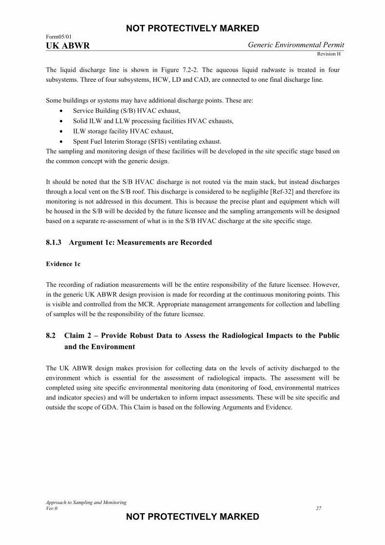
The liquid discharge line is shown in Figure 7.2-2. The aqueous liquid radwaste is treated in four
subsystems. Three of four subsystems, HCW, LD and CAD, are connected to one final discharge line.
Some buildings or systems may have additional discharge points. These are:
• Service Building (S/B) HVAC exhaust,
• Solid ILW and LLW processing facilities HVAC exhausts,
• ILW storage facility HVAC exhaust,
• Spent Fuel Interim Storage (SFIS) ventilating exhaust.
The sampling and monitoring design of these facilities will be developed in the site specific stage based on
the common concept with the generic design.
It should be noted that the S/B HVAC discharge is not routed via the main stack, but instead discharges
through a local vent on the S/B roof. This discharge is considered to be negligible [Ref-32] and therefore its
monitoring is not addressed in this document. This is because the precise plant and equipment which will
be housed in the S/B will be decided by the future licensee and the sampling arrangements will be designed
based on a separate re-assessment of what is in the S/B HVAC discharge at the site specific stage.
8.1.3 Argument 1c: Measurements are Recorded
Evidence 1c
The recording of radiation measurements will be the entire responsibility of the future licensee. However,
in the generic UK ABWR design provision is made for recording at the continuous monitoring points. This
is visible and controlled from the MCR. Appropriate management arrangements for collection and labelling
of samples will be the responsibility of the future licensee.
8.2 Claim 2 – Provide Robust Data to Assess the Radiological Impacts to the Public
and the Environment
The UK ABWR design makes provision for collecting data on the levels of activity discharged to the
environment which is essential for the assessment of radiological impacts. The assessment will be
completed using site specific environmental monitoring data (monitoring of food, environmental matrices
and indicator species) and will be undertaken to inform impact assessments. These will be site specific and
outside the scope of GDA. This Claim is based on the following Arguments and Evidence.
NOT PROTECTIVELY MARKED Form05/01 UK ABWR Generic Environmental Permit
Revision H
Approach to Sampling and Monitoring Ver.0 28
NOT PROTECTIVELY MARKED
8.2.1 Argument 2a: Representative Samples are Collected and Measured Prior to
Discharge
Evidence 2a
Gaseous Discharges
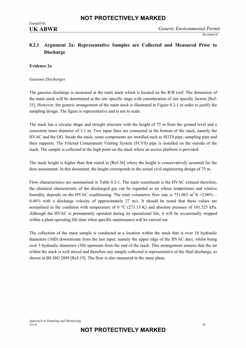
The gaseous discharge is measured at the main stack which is located on the R/B roof. The dimension of
the main stack will be determined at the site specific stage with consideration of site specific factors [Ref-
35]. However, the generic arrangement of the main stack is illustrated in Figure 8.2-1 in order to justify the
sampling design. The figure is representative and is not to scale.
The stack has a circular shape and straight structure with the height of 75 m from the ground level and a
consistent inner diameter of 3.1 m. Two input lines are connected at the bottom of the stack, namely the
HVAC and the OG. Inside the stack, some components are installed such as SGTS pipe, sampling pipe and
their supports. The Filtered Containment Venting System (FCVS) pipe is installed on the outside of the
stack. The sample is collected at the high point on the stack where an access platform is provided.
The stack height is higher than that stated in [Ref-36] where the height is conservatively assumed for the
dose assessment. In this document, the height corresponds to the actual civil engineering design of 75 m.
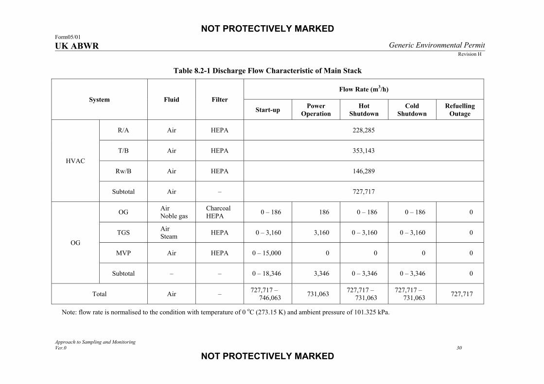
Flow characteristics are summarised in Table 8.2-1. The main constituent is the HVAC exhaust therefore,
the chemical characteristic of the discharged gas can be regarded as air whose temperature and relative
humidity depends on the HVAC conditioning. The total volumetric flow rate is 731,063 m3/h +2.06% –
0.46% with a discharge velocity of approximately 27 m/s. It should be noted that these values are
normalised in the condition with temperature of 0 °C (273.15 K) and absolute pressure of 101.325 kPa.
Although the HVAC is permanently operated during its operational life, it will be occasionally stopped
within a plant operating life time when specific maintenance will be carried out.
The collection of the main sample is conducted at a location within the stack that is over 10 hydraulic
diameters (10D) downstream from the last input, namely the upper edge of the HVAC duct, whilst being
over 3 hydraulic diameters (3D) upstream from the end of the stack. This arrangement ensures that the air
within the stack is well mixed and therefore any sample collected is representative of the final discharge, as
shown in BS ISO 2889 [Ref-19]. The flow is also measured in the same plane.

NOT PROTECTIVELY MARKED Form05/01 UK ABWR Generic Environmental Permit
Revision H
Approach to Sampling and Monitoring Ver.0 29
NOT PROTECTIVELY MARKED
Figure 8.2-1 Sketch of Main Stack
OG pipe
HVAC duct
Over 10D
Over 3D
R/B roof
Platform
- Isokinetic probe - Flow meter - Port for independent monitoring - Power supply
Sampling equipment room
SGTS pipe
Pipe with heater Sampling pipe
LegendNote Not to scale.
NOT PROTECTIVELY MARKED Form05/01 UK ABWR Generic Environmental Permit
Revision H
Approach to Sampling and Monitoring Ver.0 30
NOT PROTECTIVELY MARKED
Table 8.2-1 Discharge Flow Characteristic of Main Stack
System Fluid Filter Flow Rate (m3/h)
Start-up Power Operation
Hot Shutdown
Cold Shutdown
Refuelling Outage
HVAC
R/A Air HEPA 228,285
T/B Air HEPA 353,143
Rw/B Air HEPA 146,289
Subtotal Air – 727,717
OG
OG Air Noble gas
Charcoal HEPA 0 – 186 186 0 – 186 0 – 186 0
TGS Air Steam HEPA 0 – 3,160 3,160 0 – 3,160 0 – 3,160 0
MVP Air HEPA 0 – 15,000 0 0 0 0
Subtotal – – 0 – 18,346 3,346 0 – 3,346 0 – 3,346 0
Total Air – 727,717 – 746,063 731,063 727,717 –
731,063 727,717 –
731,063 727,717
Note: flow rate is normalised to the condition with temperature of 0 oC (273.15 K) and ambient pressure of 101.325 kPa.

NOT PROTECTIVELY MARKED Form05/01 UK ABWR Generic Environmental Permit
Revision H
Approach to Sampling and Monitoring Ver.0 31
NOT PROTECTIVELY MARKED
The discharge flow is continuously measured. The exact number and locations in the sampling plane will
be determined during the commissioning stage and will follow ISO 10780 [Ref-20]. During the
commissioning phase the air velocity profile will be determined as described within BS ISO 2889 [Ref-19]
to show the coefficient of variance is less than 20% across the centre two thirds of the stack. To provide
backup for the gaseous flow measurement a secondary identical flow monitoring system will be stored
outside of the stack. A redundant system will not be permanently installed within the stack; this is to
prevent lightning strike damaging both systems at the same time. It is estimated that the time taken to
install the spare system would be a maximum of two days. There are additional flow measurements
recorded within both the HVAC and OG as shown in Figure 7.2-1. These could be used as supplementary
information during any period where the main flow readings could be unavailable. During normal
operations it is proposed the operator records these values to show how they compare to the main flow
measurements system, which will create a robust predictive model to calculate the volumetric flow rates if
the primary system fails. It is also shown that the flow rate during normal operations is relatively stable, so
it is concluded that the maximum downtime of two days with the supplementary information and stability
of flow would not present a problem.
Samples will be collected from the stack using an isokinetic probe which will be consistent with the
requirements within BS ISO 2889 [Ref-19], to ensure that there is no preferential fractionation of the
particles within the sample relative to the main emissions. This is standard practice across all industries that
have a requirement to sample particulates in gaseous discharges. During the commissioning phase the
particle concentration profile will be determined as described within BS ISO 2889 [Ref-19] to show the
coefficient of variance is less than 20% across the centre two thirds of the stack. Multi-nozzle probes may
be used according to detail design or the commissioning tests. The location of sampling points within the
sampling plane will also be determined during the commissioning stage.
There are two types of probe commonly used for particulate sampling; shrouded and unshrouded probes.
The former is an update on the standard design. The shrouded probe offers the following benefits over the
unshrouded one:
• Lower internal wall losses,
• Better off-angle performance,
• Lower sensitivity to flow stream turbulence,
• Ability to operate in either a fixed flow or variable flow rate mode.
In addition the shrouded probes are typically less expensive than a custom rake design for a similar stack.
These are being used in the nuclear industry within the US at present and their use is outlined within BS
ISO 2889 [Ref-19].
However, there are currently no commercially available shrouded probes that are accredited for the
proposed flow rate for the UK ABWR design. Therefore unshrouded probes would represent BAT at the
current time, as this is the only type available. These probes are capable of extracting a representative
sample and currently used successfully across the industry. Dialogue will be maintained with the
manufacturers to determine if a suitable shrouded probe comes onto the market, which could offer some
additional benefits to the unshrouded version.
NOT PROTECTIVELY MARKED Form05/01 UK ABWR Generic Environmental Permit
Revision H
Approach to Sampling and Monitoring Ver.0 32
NOT PROTECTIVELY MARKED
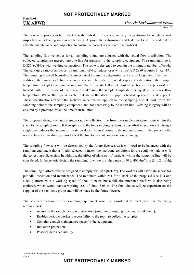
The isokinetic probe can be extracted to the outside of the stack, namely the platform, for regular visual
inspection and cleaning such as air blowing. Appropriate performance and leak checks will be undertaken
after the maintenance and inspection to ensure the correct operation of the probe(s).
The sampling flow velocities for all sampling points are adjusted with the actual flow distribution. The
collected samples are merged into one line for transport to the sampling equipment. The sampling pipe is
DN25 SCH40S with welding connections. The route is designed to contain the minimum number of bends.
The curvature ratio of all bends is a minimum of 4 to reduce loses whilst BS ISO 2889 requires 3 [Ref-19].
The sampling line will be made of stainless steel to minimise deposition and ensure longevity of the line. In
addition, the inner wall has a smooth surface. In order to avoid vapour condensation, the sample
temperature is kept to be equal to or above that of the stack flow. Almost all sections of the pipework are
located within the inside of the stack to make sure the sample temperature is equal to the stack flow
temperature. Where the pipe is located outside of the stack, the pipe is heated up above the dew point.
These specifications except the material selection are applied to the sampling line at least, from the
sampling point to the sampling equipment, and not necessarily to the return line. Welding integrity will be
ensured by a pressure test at the time of installation.
The proposed design contains a single sample collection line from the sample extraction point within the
stack to the sampling room. It then splits into the two sampling systems as described in Section 7.3. Using a
single line reduces the amount of waste produced when it comes to decommissioning. It also prevents the
need to have two heating systems to heat the line to prevent condensation occurring.
The sampling flow rate will be determined by the future licensee, as it will need to be balanced with the
sampling equipment that is finally selected to match the operating conditions for the equipment along with
the collection efficiencies. In addition, the effect of plate out of particles within the sampling line will be
considered. In the generic design, the sampling flow rate is in the range of 50 to 400 dm3/min (3 to 24 m3/h).
The sampling platform will be designed to comply with M1 [Ref-29]. The workers will have safe access for
periodic inspection and maintenance. The minimum within M1 for a stack of the proposed size is a one
sided platform with a working space of about 4.60 m, but a full circumference platform is also being
explored, which would have a working area of about 3.05 m. The final choice will be dependent on the
supplier of the isokinetic probe and will be made by the future licensee.
The selected location of the sampling equipment room is considered to meet with the following
requirements:
• Assists in the sample being representative (minimum sampling pipe length and bends),
• Enables periodic worker’s accessibility to the room to collect the samples,
• Contains enough maintenance space for the equipment,
• Radiation protection,
• Post-accident accessibility.

NOT PROTECTIVELY MARKED Form05/01 UK ABWR Generic Environmental Permit
Revision H
Approach to Sampling and Monitoring Ver.0 33
NOT PROTECTIVELY MARKED
The pipework is required to be of minimum length and minimum bends from the sampling point to the
sampling equipment [Ref-19][Ref-30]. Therefore the sampling equipment room is placed at the nearest
possible location from the main stack; just below the main stack as shown in Figure 8.2-2. Since the
sampling and monitoring is also carried out during the fault condition (N.B. not within GEP-RSR scope),
the room is located outside the secondary containment where post-accident accessibility is ensured.
The sampling pipe length is designed to be much shorter than the Standard ABWR. This is driven by the
importance of particulate sampling under UK legislation. In Japan, the primary nuclides of concern relating
to public dose are noble gas and the particulate material is regarded as secondary priority information.
Furthermore, the impact to the public is evaluated conservatively to ensure safety. Therefore, the sampling
equipment location in Japanese plants is determined by mainly the other factors such as space, post-
accident accessibility and building construction cost. For example, the long pipework schematically shown
in Figure 8.2-2 is one of the acceptable options in Japan.
The sampling pipe length of the generic design is approximately 62 m with horizontal projection of 24 m
and 22 bends from the main stack wall to the first sampling equipment. Particle penetration was modelled
by Deposition 2001a as set out in BS ISO 2889 [Ref-19]. A significant parameter to the penetration factor
is particle diameter where it is assumed to be 0.3 μm because High Efficiency Particulate Air Filter (HEPA)
filtration can remove 0.3 μm particle with over 99.9% efficiency. It is found that the penetration factor is
clearly higher than 90% under the generic design for a range of flows from 330 dm3/min down to 60
dm3/min. The values are much higher than the BS ISO 2889 requirement of 50% [Ref-19]. It should be
noted that the pipework could be changed at the site specific stage. In the worst case, the horizontal
projection will be increased up to 60 m. Should this worst case be realised, the penetration factor modelling
indicates it remains in excess of 90% for flows from 330 dm3/min down to 60 dm3/min. This is still in
excess of the requirement of BS ISO 2889 [Ref-19].
Figure 8.2-2 Main Stack Sampling Equipment Location
T/B C/B R/B
UK ABWR generic design
One of the acceptable options in Japan
Particulate filter Main stack
NOT PROTECTIVELY MARKED Form05/01 UK ABWR Generic Environmental Permit
Revision H
Approach to Sampling and Monitoring Ver.0 34
NOT PROTECTIVELY MARKED
The dedicated sampling equipment room is planned to be approximately 90 m2 at the generic design stage.
This may be modified due to the Civil Engineering development in the site specific stage, however the
work space for sample collection and maintenance will still meet the UK ABWR HF generic specification.
[Ref-37]
It is good practice to return any sample downstream of the sample extraction location to prevent either
double counting or dilution of the sample. [Ref-30] However, the return point is proposed to be located
upstream of the sample extraction point as shown in Figure 7.3-1 and Figure 8.2-1. This arrangement saves
pipework, which in turn will reduce the amount of potentially radioactively contaminated material that
needs to be disposed of at the end of the plant life. It is estimated that this could save over 30 m of pipe.
The impact of returning the gas upstream of the sampling location has been determined to be negligible.
During normal operations, the UK ABWR has a gaseous flow rate through the main stack of 731,063 m3/h,
while the maximum sampling flow rate is assumed as 24 m3/h (this is a maximum value to be conservative,
with the exact value be determined at a site specific stage.) This gives a mixing ratio of 1:30,400 which
would have insignificant impacts in terms of both dilution of sample and double counting. It is therefore
concluded that it is BAT to have the sample retuned upstream of the sampling location as the impact of
saving pipe is greater than the impact on the representativeness of the sample.
The sampling system configuration is shown in Figure 7.3-1. The system is duplicated and operates in
parallel. Each system samples or measures the items in Table 7.3-1.
Particulate sampling equipment is located at the nearest possible location to minimise plate out. Any other
equipment (e.g. flow meter) is placed downstream of the particulate sampling equipment except necessary
ones (e.g. valve). Then iodine is collected without particulates. Finally, the noble gases are continuously
measured by a gamma detector as required in BS EN 60761-3. [Ref-22] Tritium is not removed from the
sampled gas but it does not affect the gamma measurement because of its low beta energy. Tritium and
carbon-14 are both collected on another line. At each line, the sampling flow is set to be constant as
appropriate collection efficiency can be performed. In addition, the sampling flow is high enough to ensure
the required detection limit as described in Section 8.2.2. There are additional pumps which control the
total sampling flow to be constant in order to ensure the isokinetic sampling condition. When one sampling
line is isolated for sample collection or maintenance, the flow rate on the non-sampling line is increased to
keep the total sampling flow constant. All the pumps are placed downstream from any filters and measuring
unit as required in BS EN 60761-1 [Ref-21].
In addition to the main sampling location, as described in Section 8.2.2, noble gases excluding Ar-41 are
measured within the OG line before it enters the main stack (Figure 7.2-1). The only source of noble gases
comes from the OG. [Ref-32] Using this location prevents the dilution of the material by the HVAC and
therefore allows for the detection of the noble gases at the appropriate level. The air at this point will be
well mixed by passing through the charcoal adsorber and filter. After passing through these, there is no
additional input, so it is an appropriate place to collect a representative sample for noble gases.
NOT PROTECTIVELY MARKED Form05/01 UK ABWR Generic Environmental Permit
Revision H
Approach to Sampling and Monitoring Ver.0 35
NOT PROTECTIVELY MARKED
Liquid Discharges
The UK ABWR liquid discharge is a batch process. There are three subsystems connected to the one
discharge line as shown in Figure 7.2-2. Each subsystem has two holding tanks. Once the volume of a tank
reaches a pre-determined value, the liquid will need to be discharged. Prior to the discharge, the liquid in
the tank is well agitated by a pump with a circulation line. Following this, the in-process sample is
collected from that line and analysed. Once the activity is confirmed to be less than the permitted activity,
the liquid is discharged to the canal. Interlocks are in place to prevent simultaneous discharge and filling of
the tank. The inlet valve cannot be opened if the pump for the recirculation line or the discharge line is
operational. The system is designed to prevent uncharacterised liquid waste being discharged to the
environment.
Each subsystem is operated independently with the circulation line and its in-process sampling line is
unique for each holding tank. The systems are arranged to not discharge multi-tanks simultaneously by an
interlock. This arrangement can minimise contamination from the other lines and can provide better quality
data for each batch discharge.
The liquid waste discharge is sampled downstream of the confluence of three discharge lines to ensure that
it is representative of the final discharge and that no additional radioactive material can enter the system
downstream of the sampling location (Figure 7.2-2). At that point, a proportional sample is collected with
an appropriate flow meter and flow proportional sampler. [Ref-31] The exact volume of sample collected
per unit volume of discharge will be determined through a combination of the total volume discharged and
the laboratory requirements for the volume of sample required. A sampler will be selected that is capable of
obtaining a range of volumes.
The HCW and CAD and their sampling systems are located in the Rw/B, and the LD as well as the
sampling system is located in the S/B. The flow proportional sampler is located as close to the discharge
pipe as possible. The accessibility and work space for sample collection and maintenance will be designed
to meet with the UK ABWR HF generic specification. [Ref-37]
In order to avoid the situation where a technical issue with the sampling equipment could prevent discharge,
three options for mitigation were considered:
(1) Have no backup sampling system, and rely on the equipment being repaired or replaced before
the storage capacity of the tanks is breached. This is considered a significant risk to the running
of the plant and is not deemed good practice.
(2) Install a simple backup system for sample collection (such as a simple valve system) allowing
samples to be manually extracted from the effluent. It is much harder to determine if the sample
collected is representative of the discharge and also has the potential to expose workers to
additional dose.
(3) Install a redundant sampling system of the same design as the primary sampling system.

NOT PROTECTIVELY MARKED Form05/01 UK ABWR Generic Environmental Permit
Revision H
Approach to Sampling and Monitoring Ver.0 36
NOT PROTECTIVELY MARKED
It has been decided that a redundant flow meter and flow proportional sampling system should be installed.
This is because the first two options summarised above have significant drawbacks whilst, with the third
option, the likelihood of both sampling systems being inoperable at the same time is considered remote.
8.2.2 Argument 2b: Activity Measurements will be Undertaken Using Appropriate
Techniques and Instruments
Evidence 2b
Gaseous Discharges
Continuous monitoring will be provided for noble gases in the gaseous discharge stream from the main
stack. This monitoring will be conducted using a gamma detector, expected to be NaI(Tl) scintillator, but
the exact nature will be the responsibility of the future licensee. The gas chamber size and geometry will be
driven by the detector choice, and these can be optimised to ensure the appropriate detection limits can be
achieved.
As shown in Table 5.1-1, Kr-85 is not measured specifically but monitored as the noble gas gamma content.
The NaI(Tl) scintillator is RGP as noted in M11 [Ref-30]. The equipment design parameters such as the
detector type, sizes of the detector and the gas chamber, measurement time will be optimised to ensure the
detector is sensitive to the activity concentration in Table 4.2-1. Counting time will be adjusted to achieve
the sensitivity but not exceed the sampling period of the grab sampling. In addition, spectroscopy of the
grab sample of post-treated off-gas can provide additional Kr-85 specific data although it is not final
discharge point. As shown in [Ref-32], the OG is the only route which contains Kr-85. Measurement of the
post-treated off-gas is much more sensitive, because the off-gas is diluted 18,200 times at the main stack by
the HVAC flow.
In addition to the continuous monitoring systems, samples are collected from the main stack over an
appropriate timescale to allow more detailed analysis of the following radioactive species:
• Particulates (Co-60, Cs-137, Sr-90, alpha emitters),
• Iodine (I-131),
• Tritium (H-3),
• Carbon-14 (C-14).
Sample collection allows more material to be accumulated over a longer time frame, providing a sample for
analysis with a higher likelihood of producing a detectable result than continuous monitoring. Exact
timescales for sample collection will depend on the equipment available at the time of purchase, in
conjunction with the analytical method employed. However, it is expected that the sample collection period
should not exceed the reporting period and should in fact be half this time as an example shown in Figure
7.3-2. This will allow data to be collected for a reporting period, even if a sample is lost or destroyed. For
example, if monthly reporting is required, it would be good practice to collect samples over a two week
period. Having two sampling systems running in parallel in the design mitigates against the loss or

NOT PROTECTIVELY MARKED Form05/01 UK ABWR Generic Environmental Permit
Revision H
Approach to Sampling and Monitoring Ver.0 37
NOT PROTECTIVELY MARKED
destruction of samples. Furthermore, the operations of the two sampling systems are staggered; if the
sampling periods are set at two weeks, then each system will be offset in turns of the sample change, e.g.
side 1 will sample weeks 1 and 2 and side 2 will sample weeks 2 and 3 and so on.
The nuclides are collected in an order that ensures the best sample is obtained. Particulates are collected
first to minimise losses through plating out. Once particulates have been removed the sample is passed
through an appropriate iodine adsorber. Typically these samples only contain several tens of mm of
charcoal, therefore there is only a short delay through them before the sample is passed into the gas
chamber for noble gases analysis. This arrangement complies with BS EN 60761-3 [Ref-22]. Tritium and
carbon-14 are collected on a different line and the order will be determined by the specific instrument
purchased by the future licensee.
Detection limits are dependent on a wide range of variables. For gaseous monitoring specifically, sensitive
parameters include the flow rates and sampling periods. As these will not have been set at the GDA stage it
is not possible to show that specific detection limits can be achieved. However, these parameters can be
varied once the instrument types and detection methods have been determined by the future licensee to
ensure an appropriate sample is collected to achieve the required detection limits.
Methods used for the analysis will be dependent on what is available within the laboratory industry that are
BS EN ISO/IEC 17025 accredited [Ref-24], and MCERTS [Ref-23][Ref-26] where it applies. The final
decision on the location and status of an on-site laboratory will lie with the future licensee.
For information, detection limits for some radionuclides are investigated to show whether they can meet the
requirements in Table 4.2-1 under current commercially achievable assumptions. With the number of
variables there is confidence that the required detection limits can be achieved.
It is expected that the levels of Co-60 and Cs-137 will be determined using gamma spectroscopy. The
detection limits for this technique depends on count time and sample geometry. Estimations in Table 8.2-2
show that a system will meet the requirements if the future licensee equipment will perform with detection
limits of less than 10 or 30 Bq for Co-60 or Cs-137, respectively. These are achievable values; an example
of analytical detection limit given in [Ref-38] is 0.7 Bq for both nuclides analysed by a Ge semiconductor
detector with 4,000 seconds counting time. These calculations have been based on a flow rate of 3 m3/h. A
commercially available filter housing has a range of acceptable flow rate (e.g. 0.6 to 6 m3/h), so there is the
possibility to increase the flow rate if required.

NOT PROTECTIVELY MARKED Form05/01 UK ABWR Generic Environmental Permit
Revision H
Approach to Sampling and Monitoring Ver.0 38
NOT PROTECTIVELY MARKED
Table 8.2-2 Estimated Activity of Particulate Sample (Gamma Emitters)
Parameter Co-60 Cs-137 Unit Reference
Assumed activity concentration 1E–02 3E–02 Bq/m3 [Ref-17]
Sampling flow rate 3 3 m3/h Example
Sampling period 336 336 hour Example
Activity of sample 10 30 Bq –
It is expected that Sr-90 will be analysed using liquid scintillation counting, however, this will be
dependent on which accredited methods are commercially available at the time of procurement. The flow
rate for the collection of particulate material as well as the sampling period can be adjusted to ensure
compliance with the required detection limit. An estimation in Table 8.2-3 shows a system will meet the
requirement if the future licensee equipment will perform with a detection limit of less than 20 Bq. An
example of analytical detection limit given in [Ref-38] is 2 Bq with a proportional counter and 10 minutes
counting time. As with the gamma emitting nuclides, the flow rate used is in the middle of the typical range
for particulate sampling equipment.
Table 8.2-3 Estimated Activity of Particulate Sample (Beta Emitters)
Parameter Sr-90 Unit Reference
Assumed activity concentration 2E–02 Bq/m3 [Ref-17]
Sampling flow rate 3 m3/h Example
Sampling period 336 hour Example
Activity of sample 20 Bq –
Alpha emitters are commonly detected using either alpha spectroscopy or Inductively Coupled Plasma –
Mass Spectrometry (ICP-MS), both of which are capable of low detection limits. An estimation in Table
8.2-4 shows a system will meet the requirement if the future licensee equipment will perform with a
detection limit less than 10 Bq. An example of analytical detection limit given in [Ref-38] is 4E-02 Bq with
a ZnS(Ag) scintillator and 10 minutes counting time. As with the gamma emitting nuclides, the flow rate
used is in the middle of the typical range for particulate sampling equipment.

NOT PROTECTIVELY MARKED Form05/01 UK ABWR Generic Environmental Permit
Revision H
Approach to Sampling and Monitoring Ver.0 39
NOT PROTECTIVELY MARKED
Table 8.2-4 Estimated Activity of Particulate Sample (Alpha Emitters)
Parameter Total alpha Unit Reference
Assumed activity concentration 1E-02 Bq/m3 [Ref-17]
Sampling flow rate 3 m3/h Example
Sampling period 336 hour Example
Activity of sample 10 Bq –
It is expected that the level of I-131 will be determined using gamma spectroscopy. An estimation in Table
8.2-5 shows a system will meet the requirement if a detection limit of 11.6 Bq can be achieved. This value
includes radioactive decay during the sample collection. A commercially available filter housing has a
range of acceptable flow rate, so there is the possibility to change the flow rate if required. An example of
analytical detection limit given in [Ref-38] is 1 Bq with a Ge semiconductor detector with 4,000 seconds
counting time, which shows the method would be a suitable one to use.
Table 8.2-5 Estimated Activity of Iodine Sample
Parameter I-131 Unit Reference
Assumed activity concentration 2E–02 Bq/m3 [Ref-17]
Sampling flow rate 3 m3/h Example
Sampling period 336 hour Example
Half life 8.02 day [Ref-39]
Activity of sample 11.6 Bq –
The detection limit requirements for both H-3 and C-14 are significantly higher than those for the other
nuclides. It is expected these will be collected using a bubbler system and with final analysis being
conducted by liquid scintillation, however, this will be dependent on which MCERTS methods are
commercially available. It will be the responsibility of the future licensee to request laboratories obtain
MCERTS accreditation if they do not currently have it. The flow rate through the bubblers and collection
times can be adjusted to achieve the appropriate detection limit. An estimation in Table 8.2-6 shows a
system will meet the requirement if the future licensee equipment will perform detection limit less than
2E+08 or 2E+06 Bq/m3 for H-3 or C-14, respectively. Whilst an example of analytical detection limit for
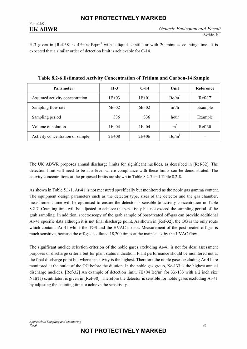
NOT PROTECTIVELY MARKED Form05/01 UK ABWR Generic Environmental Permit
Revision H
Approach to Sampling and Monitoring Ver.0 40
NOT PROTECTIVELY MARKED
H-3 given in [Ref-38] is 4E+04 Bq/m3 with a liquid scintillator with 20 minutes counting time. It is
expected that a similar order of detection limit is achievable for C-14.
Table 8.2-6 Estimated Activity Concentration of Tritium and Carbon-14 Sample
Parameter H-3 C-14 Unit Reference
Assumed activity concentration 1E+03 1E+01 Bq/m3 [Ref-17]
Sampling flow rate 6E–02 6E–02 m3/h Example
Sampling period 336 336 hour Example
Volume of solution 1E–04 1E–04 m3 [Ref-30]
Activity concentration of sample 2E+08 2E+06 Bq/m3 –
The UK ABWR proposes annual discharge limits for significant nuclides, as described in [Ref-32]. The
detection limit will need to be at a level where compliance with these limits can be demonstrated. The
activity concentrations at the proposed limits are shown in Table 8.2-7 and Table 8.2-8.
As shown in Table 5.1-1, Ar-41 is not measured specifically but monitored as the noble gas gamma content.
The equipment design parameters such as the detector type, sizes of the detector and the gas chamber,
measurement time will be optimised to ensure the detector is sensible to activity concentration in Table
8.2-7. Counting time will be adjusted to achieve the sensitivity but not exceed the sampling period of the
grab sampling. In addition, spectroscopy of the grab sample of post-treated off-gas can provide additional
Ar-41 specific data although it is not final discharge point. As shown in [Ref-32], the OG is the only route
which contains Ar-41 whilst the TGS and the HVAC do not. Measurement of the post-treated off-gas is
much sensitive, because the off-gas is diluted 18,200 times at the main stack by the HVAC flow.
The significant nuclide selection criterion of the noble gases excluding Ar-41 is not for dose assessment
purposes or discharge criteria but for plant status indication. Plant performance should be monitored not at
the final discharge point but where sensitivity is the highest. Therefore the noble gases excluding Ar-41 are
monitored at the outlet of the OG before the dilution. In the noble gas group, Xe-133 is the highest annual
discharge nuclides. [Ref-32] An example of detection limit, 7E+04 Bq/m3 for Xe-133 with a 2 inch size
NaI(Tl) scintillator, is given in [Ref-38]. Therefore the detector is sensible for noble gases excluding Ar-41
by adjusting the counting time to achieve the sensitivity.
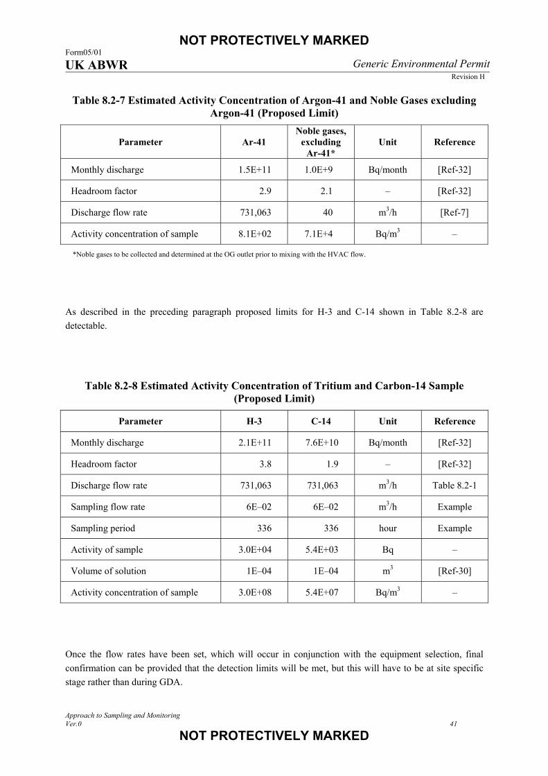
NOT PROTECTIVELY MARKED Form05/01 UK ABWR Generic Environmental Permit
Revision H
Approach to Sampling and Monitoring Ver.0 41
NOT PROTECTIVELY MARKED
Table 8.2-7 Estimated Activity Concentration of Argon-41 and Noble Gases excluding Argon-41 (Proposed Limit)
Parameter Ar-41 Noble gases,
excluding Ar-41*
Unit Reference
Monthly discharge 1.5E+11 1.0E+9 Bq/month [Ref-32]
Headroom factor 2.9 2.1 – [Ref-32]
Discharge flow rate 731,063 40 m3/h [Ref-7]
Activity concentration of sample 8.1E+02 7.1E+4 Bq/m3 –
*Noble gases to be collected and determined at the OG outlet prior to mixing with the HVAC flow.
As described in the preceding paragraph proposed limits for H-3 and C-14 shown in Table 8.2-8 are
detectable.
Table 8.2-8 Estimated Activity Concentration of Tritium and Carbon-14 Sample (Proposed Limit)
Parameter H-3 C-14 Unit Reference
Monthly discharge 2.1E+11 7.6E+10 Bq/month [Ref-32]
Headroom factor 3.8 1.9 – [Ref-32]
Discharge flow rate 731,063 731,063 m3/h Table 8.2-1
Sampling flow rate 6E–02 6E–02 m3/h Example
Sampling period 336 336 hour Example
Activity of sample 3.0E+04 5.4E+03 Bq –
Volume of solution 1E–04 1E–04 m3 [Ref-30]
Activity concentration of sample 3.0E+08 5.4E+07 Bq/m3 –
Once the flow rates have been set, which will occur in conjunction with the equipment selection, final
confirmation can be provided that the detection limits will be met, but this will have to be at site specific
stage rather than during GDA.
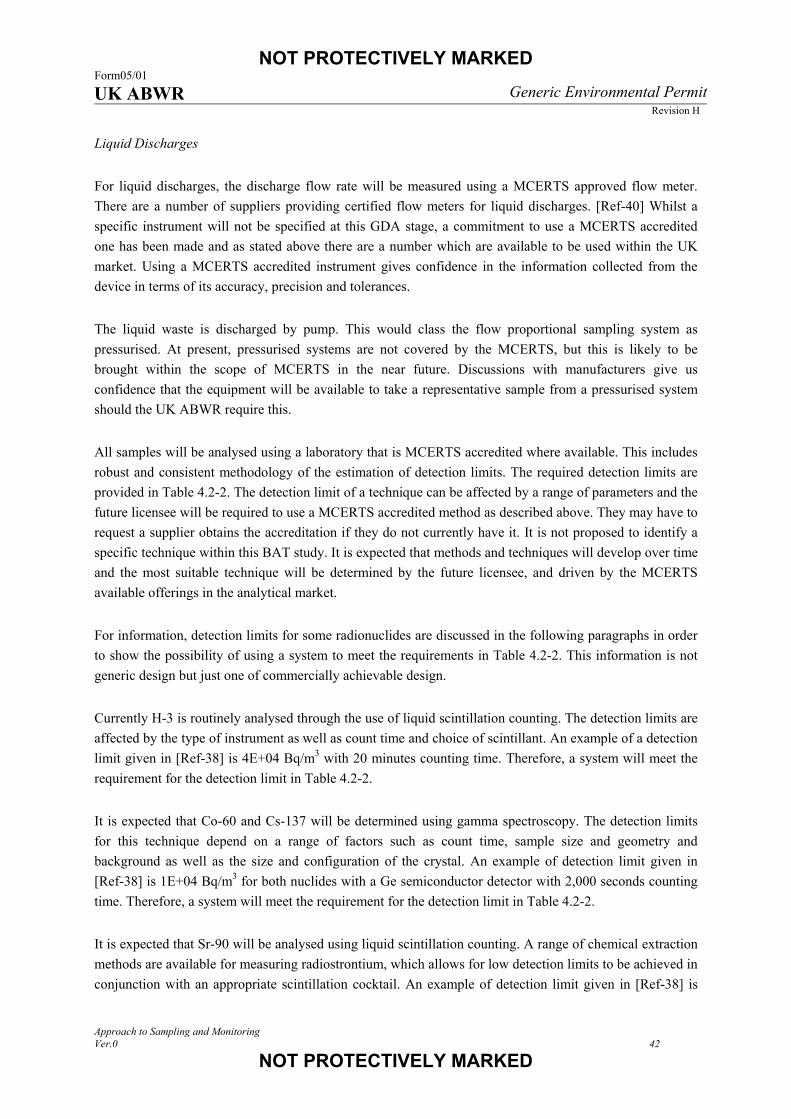
NOT PROTECTIVELY MARKED Form05/01 UK ABWR Generic Environmental Permit
Revision H
Approach to Sampling and Monitoring Ver.0 42
NOT PROTECTIVELY MARKED
Liquid Discharges
For liquid discharges, the discharge flow rate will be measured using a MCERTS approved flow meter.
There are a number of suppliers providing certified flow meters for liquid discharges. [Ref-40] Whilst a
specific instrument will not be specified at this GDA stage, a commitment to use a MCERTS accredited
one has been made and as stated above there are a number which are available to be used within the UK
market. Using a MCERTS accredited instrument gives confidence in the information collected from the
device in terms of its accuracy, precision and tolerances.
The liquid waste is discharged by pump. This would class the flow proportional sampling system as
pressurised. At present, pressurised systems are not covered by the MCERTS, but this is likely to be
brought within the scope of MCERTS in the near future. Discussions with manufacturers give us
confidence that the equipment will be available to take a representative sample from a pressurised system
should the UK ABWR require this.
All samples will be analysed using a laboratory that is MCERTS accredited where available. This includes
robust and consistent methodology of the estimation of detection limits. The required detection limits are
provided in Table 4.2-2. The detection limit of a technique can be affected by a range of parameters and the
future licensee will be required to use a MCERTS accredited method as described above. They may have to
request a supplier obtains the accreditation if they do not currently have it. It is not proposed to identify a
specific technique within this BAT study. It is expected that methods and techniques will develop over time
and the most suitable technique will be determined by the future licensee, and driven by the MCERTS
available offerings in the analytical market.
For information, detection limits for some radionuclides are discussed in the following paragraphs in order
to show the possibility of using a system to meet the requirements in Table 4.2-2. This information is not
generic design but just one of commercially achievable design.
Currently H-3 is routinely analysed through the use of liquid scintillation counting. The detection limits are
affected by the type of instrument as well as count time and choice of scintillant. An example of a detection
limit given in [Ref-38] is 4E+04 Bq/m3 with 20 minutes counting time. Therefore, a system will meet the
requirement for the detection limit in Table 4.2-2.
It is expected that Co-60 and Cs-137 will be determined using gamma spectroscopy. The detection limits
for this technique depend on a range of factors such as count time, sample size and geometry and
background as well as the size and configuration of the crystal. An example of detection limit given in
[Ref-38] is 1E+04 Bq/m3 for both nuclides with a Ge semiconductor detector with 2,000 seconds counting
time. Therefore, a system will meet the requirement for the detection limit in Table 4.2-2.
It is expected that Sr-90 will be analysed using liquid scintillation counting. A range of chemical extraction
methods are available for measuring radiostrontium, which allows for low detection limits to be achieved in
conjunction with an appropriate scintillation cocktail. An example of detection limit given in [Ref-38] is
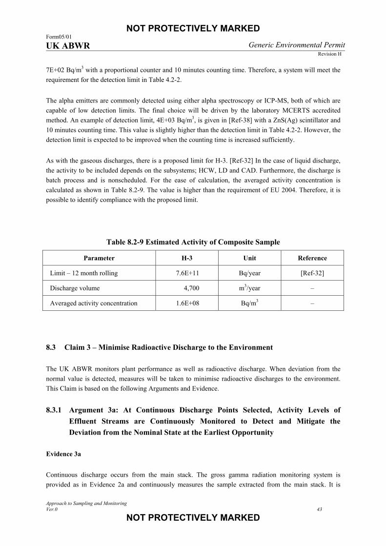
NOT PROTECTIVELY MARKED Form05/01 UK ABWR Generic Environmental Permit
Revision H
Approach to Sampling and Monitoring Ver.0 43
NOT PROTECTIVELY MARKED
7E+02 Bq/m3 with a proportional counter and 10 minutes counting time. Therefore, a system will meet the
requirement for the detection limit in Table 4.2-2.
The alpha emitters are commonly detected using either alpha spectroscopy or ICP-MS, both of which are
capable of low detection limits. The final choice will be driven by the laboratory MCERTS accredited
method. An example of detection limit, 4E+03 Bq/m3, is given in [Ref-38] with a ZnS(Ag) scintillator and
10 minutes counting time. This value is slightly higher than the detection limit in Table 4.2-2. However, the
detection limit is expected to be improved when the counting time is increased sufficiently.
As with the gaseous discharges, there is a proposed limit for H-3. [Ref-32] In the case of liquid discharge,
the activity to be included depends on the subsystems; HCW, LD and CAD. Furthermore, the discharge is
batch process and is nonscheduled. For the ease of calculation, the averaged activity concentration is
calculated as shown in Table 8.2-9. The value is higher than the requirement of EU 2004. Therefore, it is
possible to identify compliance with the proposed limit.
Table 8.2-9 Estimated Activity of Composite Sample
Parameter H-3 Unit Reference
Limit – 12 month rolling 7.6E+11 Bq/year [Ref-32]
Discharge volume 4,700 m3/year –
Averaged activity concentration 1.6E+08 Bq/m3 –
8.3 Claim 3 – Minimise Radioactive Discharge to the Environment
The UK ABWR monitors plant performance as well as radioactive discharge. When deviation from the
normal value is detected, measures will be taken to minimise radioactive discharges to the environment.
This Claim is based on the following Arguments and Evidence.
8.3.1 Argument 3a: At Continuous Discharge Points Selected, Activity Levels of
Effluent Streams are Continuously Monitored to Detect and Mitigate the
Deviation from the Nominal State at the Earliest Opportunity
Evidence 3a
Continuous discharge occurs from the main stack. The gross gamma radiation monitoring system is
provided as in Evidence 2a and continuously measures the sample extracted from the main stack. It is

NOT PROTECTIVELY MARKED Form05/01 UK ABWR Generic Environmental Permit
Revision H
Approach to Sampling and Monitoring Ver.0 44
NOT PROTECTIVELY MARKED
common practice to monitor gamma emitting noble gases as they are relatively easy to detect and are good
indicators of plant performance. The system will be capable of providing real time data to the operating
personnel in the MCR. The delay time is estimated to be less than 10 minutes, taking into account the
pipework design, gas chamber size, sampling flow rate, and counting time. The measurement is recorded in
the MCR in order to provide trend data which is essential information to identify the deviation from the
nominal value. Should the radiation level increase, the alarm is activated in the MCR to alert the operating
personnel.
8.3.2 Argument 3b: In-process Monitoring and Sampling Arrangements are Provided
to Detect the Deviation from the Nominal State Earlier than those at Final
Discharge Points
Evidence 3b
When the activity of the off-gas increases, there is significant time delay in identifying such an increase at
the main stack. This is because the detection takes place following the holdup time of the noble gas (more
than 30 days for xenon, 40 hours for krypton [Ref-41]). Therefore, an additional measure is provided to
detect the deviation earlier and further upstream. The major source of any increase of the radiation level of
the off-gas is fuel failure.
The following monitoring and sampling system is provided to detect and locate the fuel failure:
• OG pre-treatment radiation monitor – continuous measurement,
• OG pre-treatment nuclide analysis – periodic grab sampling.
A continuous radiation monitoring system is provided to rapidly detect the change of activity level. A grab
sampling system is also provided for detail analysis allowing the off-gas to be collected in a vial and
analysed at the on-site laboratory. Although it takes longer, such analysis can provide nuclide specific data
with a higher sensitivity. In addition, reactor water is sampled and then dissolved iodine is analysed as a
double check in order to verify the failure.
The management of the fuel failure is described in Section 5.1.4.2 in [Ref-7]. Under normal operation,
periodic sampling and analyses of off-gas and reactor water shows a stable operating state. If the radiation
level reaches increases to the Criteria 1 in Figure 5.1.4.2-1 in [Ref-7], the frequency of sampling is
increased. If the size of the pinhole becomes larger and the radiation level reaches the Criteria 2, a Power
Suppression Test (PST) is carried out to identify and isolate the fuel bundle in which there is a failure. Grab
sampling can provide nuclide specific data to indicate even slight signs of deviation from the normal state.
If the radiation levels become high enough, gross gamma radiation level is measured to continuously
follow the event. The level of gross gamma radiation closely tracks when the control rods are sequentially
fully inserted and fully extracted.
NOT PROTECTIVELY MARKED Form05/01 UK ABWR Generic Environmental Permit
Revision H
Approach to Sampling and Monitoring Ver.0 45
NOT PROTECTIVELY MARKED
For high sensitive detection, the targeted parameter should have the following characteristics.
• Good signal to noise ratio; small deviation from the normal operating state is identifiable,
• Fast response,
• Easy to identify the reason for the parameter change.
When fuel failure has occurred, gaseous fission product is leaked from the fuel cladding tube and the
parameters shown in Table 8.3-1 and Table 8.3-2 would be affected. In general, the flow of gas is faster
than that of liquid. Thus measurement of gas provides the fastest response. In Table 8.3-1 and Table 8.3-2,
activity in non-condensable gas is considered to be the most sensitive parameter. It is regarded that gross
gamma measurement is the best method for continuous monitoring, and gamma spectroscopy is the best
method for nuclide specific analysis. The activity in liquid is also monitored. [Ref-42] The measurements
can be used for cross checking of the gas measurement.

NOT PROTECTIVELY MARKED Form05/01 UK ABWR Generic Environmental Permit
Revision H
Approach to Sampling and Monitoring Ver.0 46
NOT PROTECTIVELY MARKED
Table 8.3-1 Monitoring Parameters to Detect Fuel Failure (Gas)
Parameter Parameter Change Detection Sensitivity Response Monitoring
Activity in non-condensable gas
Leaked gas is transported to turbine and treated in OG.
Activity of main steam and off-gas is increased.
Fission product is discharged.
Radiation level of off-gas is monitored.
Faster response than liquid; flow speed of gas is faster than liquid.
Nuclear analysis such as gamma spectrometry is more sensitive than chemical analysis.
Origin of radioactivity is easily identified as fuel.
Yes
Composition in non-condensable gas
Leaked gas is transported to turbine and treated in OG.
Composition of main steam and off-gas is changed.
Fission product is discharged.
Composition of off-gas is monitored.
Faster response than liquid; flow speed of gas is faster than liquid.
Chemical analysis such as gas chromatograph is less sensitive than nuclear analysis.
No
Activity in condensable gas
Leaked gas is transported to turbine and condensate is returned to reactor
Activity of main steam and condensate is increased.
Fission product is filtered at Condensate Filter System (CF) and Condensate Demineraliser System (CD)
Radiation level of condensate is monitored.
Later response than gas; flow speed of liquid is slower than gas.
Origin of radioactivity is easily identified as fuel.
No

NOT PROTECTIVELY MARKED Form05/01 UK ABWR Generic Environmental Permit
Revision H
Approach to Sampling and Monitoring Ver.0 47
NOT PROTECTIVELY MARKED
Table 8.3-2 Monitoring Parameters to Detect Fuel Failure (Liquid)
Parameter Parameter Change Detection Sensitivity Response Monitoring
Activity in liquid
Leaked soluble gas such as iodine is dissolved in reactor water.
Activity of reactor water increases.
Fission product is filtered at Reactor Water Clean-up System (CUW).
Radiation level of reactor water is monitored.
Later response than gas; flow speed of liquid is slower than gas.
Nuclear analysis such as gamma spectrometry is more sensitive than chemical analysis.
Origin of radioactivity is easily identified as fuel.
Yes
Conductivity in liquid
Leaked soluble gas is dissolved in reactor water.
Conductivity of reactor water increases.
Fission product is filtered at CUW.
Conductivity of reactor water is monitored.
Later response than gas; flow speed of liquid is slower than gas.
Small conductivity change due to large volume of reactor water.
Not only fuel failure but some candidates can be regarded as reason of conductivity increase.
No
pH in liquid
Leaked soluble gas is dissolved in reactor water.
pH of reactor water changes.
Fission product is filtered at CUW.
pH of reactor water is monitored.
Later response than gas; flow speed of liquid is slower than gas.
Small pH change due to large volume of reactor water.
Not only fuel failure but some candidates can be regarded as reason of pH increase.
No
NOT PROTECTIVELY MARKED Form05/01 UK ABWR Generic Environmental Permit
Revision H
Approach to Sampling and Monitoring Ver.0 48
NOT PROTECTIVELY MARKED
For high sensitivity of detection, the targeted radionuclides should have the following characteristics:
• High fission yield and high branching ratio,
• Long half life (a short half life nuclide will be decayed before it is measured),
• Hundreds of keV of gamma emitter; if Ge semiconductor detector with relative efficiency such as
10 – 20% is used for nuclide analysis, detection efficiency is highest at around hundreds of keV.
From Table 8.3-3, Xe-133 and Xe-138 are regarded as the most suitable radionuclides to detect a fuel
failure. Some of the other xenon and krypton isotopes are detectable. Although these radionuclides are not
used for the criteria to identify the fuel failure, the measurements are recorded and used to calculate the
noble gas release rate.
There are a number of options for the sampling point. For high sensitive detection, the sampling point
should be as follows:
• High activity concentration; vapour dilutes the activity concentration.
• Low pressure, low temperature; sampling system becomes simpler.
• Low humidity; vapour is condensed in the sampling system.
• Low hydrogen concentration.
• Short delay time between fuel to detector.
From Table 8.3-4 the section between the OG cooler condenser and the OG charcoal adsorber is regarded
as the best location to detect and monitor the fuel failure. Response time depends on the pipe length and
flow speed. A typical value of delay time does not exceed 60 minutes from the reactor to the detector.
Sampling is also undertaken in the main stack, although this is to ensure compliance with the
Environmental Permit discharge limits rather than provide warning of a fuel pin failure.
In the case of the grab sampling system, the gas sample is transported to the outside of the OG equipment
room and finally collected at a shielded area in order to decrease occupational radiation exposure during the
sampling procedure.
The detector for continuous monitoring is also placed in a shielded area along the sampling line. If the
detector is placed near the OG line to measure the radiation level of off-gas directly, it is exposed to high
radiation from the OG equipment and pipes. The main background in the OG area is N-16. High
background level decreases the detection sensitivity for the noble gas. Therefore the detector should be
placed at the shielded area to measure the radiation level of the sampled gas. The sampled gas is returned
upstream of the OG; at the inlet pipe of Steam Jet Air Ejector (SJAE). This arrangement makes differential
sampling possible. From the main condenser to the SJAE, the pressure inside the pipe is kept as a vacuum
condition. Therefore, the sampling system does not require a pump to collect the sample and the reliability
of the system is increased due to lack of active component.

NOT PROTECTIVELY MARKED Form05/01 UK ABWR Generic Environmental Permit
Revision H
Approach to Sampling and Monitoring Ver.0 49
NOT PROTECTIVELY MARKED
Table 8.3-3 Monitoring Nuclides to Detect Fuel Failure
Nuclide Fission Yield
[Ref-43] Half Life [Ref-39]
Gamma Energy (keV)
[Ref-39]
Branching Ratio (%)
[Ref-39]
Monitoring
Kr-85 3.27E-03 10.76 y 514 0.43
Kr-85m 1.40E-02 4.48 h 151 75.0
Kr-87 2.60E-02 76.3 m 403 49.6
Kr-88 3.51E-02 2.84 h
196 26.0
835 13.0
2,392 34.6
Kr-89 4.51E-02 3.15 m 586 16.6
1,534 5.1
Kr-90 4.86E-02 32.32 s 122 35.5
1,538 9.7
Kr-91 3.34E-02 8.57 s 507 19.1
Xe-131m 3.18E-04 11.84 d 164 1.9
Xe-133 6.69E-02 5.24 d 81 38.0 Yes
Xe-133m 1.96E-03 2.19 d 233 10
Xe-135 6.52E-02 9.14 h 250 90
608 2.9
Xe-135m 1.22E-02 15.29 m 527 80.5
Xe-137 6.10E-02 3.82 m 455 31
Xe-138 6.30E-02 14.08 m
258 31.5
Yes 435 20.3
1,768 16.7
2016 12.3
Xe-139 5.03E-02 39.68 s 219 56
Xe-140 3.65E-02 13.60 s 806 20

NOT PROTECTIVELY MARKED Form05/01 UK ABWR Generic Environmental Permit
Revision H
Approach to Sampling and Monitoring Ver.0 50
NOT PROTECTIVELY MARKED
Table 8.3-4 In-process Monitoring Locations to Detect Fuel Failure (1/2)
Symbol (Figure 7.2-1)
Location Advantage Disadvantage Monitoring
A Inner Reactor Pressure Vessel (RPV) Fastest response Extremely high background level due to
nuclear fuel and nuclear fission.
High safety grade equipment is required. No
B
Main steam line (from RPV to turbine)
Fast response High background level of N-16.
Low activity concentration.
High pressure, high temperature.
High vapour concentration.
High hydrogen concentration (dry condition).
No
C
From main condenser to SJAE
Low activity concentration.
Vacuum condition.
High vapour concentration.
High hydrogen concentration (dry condition).
No
D
From SJAE to OG recombiner
Low activity concentration.
High temperature.
High vapour concentration.
High hydrogen concentration (dry condition).
No
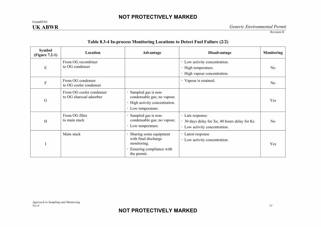
NOT PROTECTIVELY MARKED Form05/01 UK ABWR Generic Environmental Permit
Revision H
Approach to Sampling and Monitoring Ver.0 51
NOT PROTECTIVELY MARKED
Table 8.3-4 In-process Monitoring Locations to Detect Fuel Failure (2/2)
Symbol (Figure 7.2-1)
Location Advantage Disadvantage Monitoring
E
From OG recombiner to OG condenser
Low activity concentration.
High temperature.
High vapour concentration.
No
F From OG condenser to OG cooler condenser
Vapour is retained. No
G
From OG cooler condenser to OG charcoal adsorber
Sampled gas is non-condensable gas; no vapour.
High activity concentration.
Low temperature.
Yes
H
From OG filter to main stack
Sampled gas is non-condensable gas; no vapour.
Low temperature.
Late response:
30 days delay for Xe, 40 hours delay for Kr.
Low activity concentration.
No
I
Main stack Sharing some equipment with final discharge monitoring.
Ensuring compliance with the permit.
Latest response
Low activity concentration. Yes

NOT PROTECTIVELY MARKED Form05/01 UK ABWR Generic Environmental Permit
Revision H
Approach to Sampling and Monitoring Ver.0 52
NOT PROTECTIVELY MARKED
8.3.3 Argument 3c: Locations of In-process Monitoring and Sampling are Selected as
they can Identify Position of Source
Evidence 3c
Gaseous Discharges
Two of the three inputs into the main stack are subject to in-process monitoring. These are the off-gas and
TGS off-gas. The HVAC from the controlled areas are not subjected to in-process monitoring. Although
the HVAC is the major input in terms of volume of air, the activity is very low compared with the OG
[Ref-32], hence, only the OG and TGS are monitored. As the overall discharge is monitored at the main
stack, should elevated levels be recorded there and the two other contributory systems are not registering
elevated levels, then by deduction, the increase in activity is coming from the HVAC system. In addition
there are area monitors located within the controlled areas, which would indicate if there is an issue with
elevated activity in those areas. This approach reduces the number of sampling and monitoring systems that
need to be purchased, maintained and disposed of, whilst still allowing all systems to be monitored.
Both the sampling points for the post-treated off-gas and TGS off-gas locate downstream of all the
abatement technologies used within the systems and no further radioactive stream inputs to downstream of
the sampling points. Note that the sampling point for the post-treated off-gas locates upstream of the OG
ejector where the dilution of the off-gas occurs by the entirely non-radioactive driving air. This design
allows an indication of the level that will be discharged to the environment as described in Section 8.2.2.
Liquid Discharges
The three subsystems, HCW, LD and CAD, are connected to the final discharge line. Each subsystem has a
pair of holding tanks, and each tank has its own recirculation line with an in-process sampling system,
which allows any elevated activity concentrations to be identified before the effluent is sent to the final
discharge line.
8.3.4 Argument 3d: For Batch Discharge Points, Means is Provided to Prevent Human
Error
Evidence 3d
Discharges from the three subsystems (HCW, LD and CAD) are made on a batch basis. Each subsystem
has a pair of holding tanks. Once a tank is ready for discharge a specific sequence of operations will be
initiated using appropriate interlocks to ensure no additional material can be added to the tank.

NOT PROTECTIVELY MARKED Form05/01 UK ABWR Generic Environmental Permit
Revision H
Approach to Sampling and Monitoring Ver.0 53
NOT PROTECTIVELY MARKED
Each tank has a recirculation system which is used to ensure the contents are well mixed and a
representative sample can be collected for compliance purposes. It should be noted that this is not the data
which will be provided to the environmental regulator as a record of discharge, but will be used to ensure
the waste is within the discharge limits. The sample will be subjected to the same analysis criteria as the
final discharge point.
Following verification of the results the tank will be discharged to the canal, where it will be subject to
final discharge sampling using a proportional flow sampler, as described earlier, which will constitute the
final discharge results. As a failsafe, a continuous monitoring system will be located downstream of the
circulation line as shown in Figure 7.2-2. Should the radiation level exceeds a pre-determined level, it will
close the isolation valve automatically, activating an alarm in the control room; this is not an expected
scenario.
NOT PROTECTIVELY MARKED Form05/01 UK ABWR Generic Environmental Permit
Revision H
Approach to Sampling and Monitoring Ver.0 54
NOT PROTECTIVELY MARKED
9. Independent Sampling
Independent sampling systems are provided for the final discharge points for use by the regulator or their
representatives. No independent continuous monitoring system is provided, but all data and quality control
information will be made available for audit purposes. The use of the independent sampling system by the
regulators will not interrupt the operators own sampling or off-set the quality of that measurement.
9.1 Gaseous Sampling
The UK ABWR main stack sampling design is illustrated in Figure 7.3-1. The system is duplicated and
each system samples or measures the items in Table 7.3-1. The isokinetic probe, sampling pipe, and return
pipe are common for both systems. All the sampling and monitoring equipment is located in the same room.
It is proposed that appropriate measures are put in place for the environmental regulator to secure use of
one of the systems during the period when it wishes to conduct independent sampling. This would be in the
form of sealing off the system with tamperproof seals so that filters, cartridges, etc. cannot be accessed by
the future licensee, unless in an emergency and with prior consent from the environmental regulator. In
addition, tamperproof seals will be placed on associated valves. This would allow the environmental
regulator the ability to collect independent samples for particulate, iodine, tritium, and carbon-14. There is
no requirement for the environmental regulator to have independent access to the noble gases monitoring
system.
Both systems will be run at all times when the environmental regulator does not require access; the system
will be maintained and calibrated by the operating personnel to ensure representative samples are being
collected. When the environmental regulator is using one of the sampling systems, there will be no impact
on the operator’s ability to collect samples using the mirrored system. Furthermore, the total sampling flow
rate will be controlled as constant in order to maintain the isokinetic sampling when sampling lines are
isolated.
In addition to access to the sampling equipment located within the sampling room, a sampling port on the
main stack will also be provided for independent flow measurement, as close to the sample extraction point
as is feasibly possible. The design of the access ports will be consistent with the requirements laid out in
M1 (e.g. minimum diameter of 125 mm) [Ref-29]. Appropriate access arrangements will be provided and
shared with the standard access to the sample extraction point. Three standard UK waterproof sockets of
single phase 110 V will also be provided.
9.2 Liquid Sampling
The UK ABWR liquid discharge sampling design is illustrated in Figure 7.2-2. As Figure 7.2-2 shows there
is built-in redundancy within the sampling design, in that there are two flow proportional samplers, both of
which will be MCERTS accredited. During normal operation only one sampler will be in active use.

NOT PROTECTIVELY MARKED Form05/01 UK ABWR Generic Environmental Permit
Revision H
Approach to Sampling and Monitoring Ver.0 55
NOT PROTECTIVELY MARKED
However, both systems will be maintained and calibrated by the operating personnel in line with
manufacturer’s requirements. They will also be tested during commissioning to ensure they are both
collecting a representative sample.
When the environmental regulator needs to collect an independent sample, they will have exclusive access
to one of the systems. The sampler will have the ability to be sealed using tamperproof seals during the
entire sampling period, which may be as long as two weeks. The system will have the ability to vary the
amount of sample collected, so the environmental regulator can specify this before sampling commences
(because their laboratory requirements may be different from the future licensee’s). The collected sample
will allow for all analytes to be determined. When the environmental regulator is using one of the sampling
systems, there will be no impact on the operator’s ability to collect samples via the other system.

NOT PROTECTIVELY MARKED Form05/01 UK ABWR Generic Environmental Permit
Revision H
Approach to Sampling and Monitoring Ver.0 56
NOT PROTECTIVELY MARKED
10. Responsibilities for Future Licensee
In some instances where it falls to the responsibility of the future licensee, information will be developed
following GDA as part of the site specific permitting application. A list of responsibilities of the future
licensee is shown in Table 10-1.
Table 10-1 Responsibilities for Future Licensee
Section Action Delivery Phase
7.1 Selection of the sampling and monitoring equipment for the determination of the discharges. Designing the relevant instrumentations as well as sampling flow rate.
Site license permission
7.3 Sampling mechanism confirmed for the sampling period for each type of sample collection. Site license permission
8.1.2 Identification of an additional discharge route. Site license permission
8.1.3 Recording of the measurements. Site license permission Operation
8.2.1 Review of the main stack sampling design for a site specific main stack design. Site license permission
8.2.1 The flow velocity and particle concentration profile will be determined to confirm the flow measurement and sampling point(s) location(s) within the stack.
Commissioning
8.2.1 Selection of type of the isokinetic probe for the main stack sampling, e.g. shrouded or unshrouded. Commissioning
8.2.1 Determine appropriate performance and leak checks will be undertaken after the maintenance and inspection to ensure the correct operation of the probe(s).
Site license permission
8.2.1 Determination of the main stack platform design. Site license permission
8.2.1 Determining volume of the liquid sample collected per unit of volume of discharge. Site license permission
8.2.2 Ensure all sampling and monitoring techniques achieve EU 2004 detection limits. Site license permission
8.2.2 Selection of the type of accreditation for the on-site laboratory. Analysing water with MCERTS accredited laboratories.
Site license permission or commissioning

NOT PROTECTIVELY MARKED Form05/01 UK ABWR Generic Environmental Permit
Revision H
Approach to Sampling and Monitoring Ver.0 57
NOT PROTECTIVELY MARKED
11. Conclusions
This document describes, at a high level, the design approaches to the sampling, measurement and
monitoring regime that will be included in the UK ABWR design. The BAT cese is demonstrated in the
generic design level.
Hitachi-GE believes that the contents of this document meet the requirements as set out in the P&ID (Item
6, Table 1 in [Ref-1]) and the UK ABWR sampling and monitoring design correctly represent the BAT
case. A table of how the requirements have been met and how the design aligns with the other standards
and guidance is provided in Appendix A.
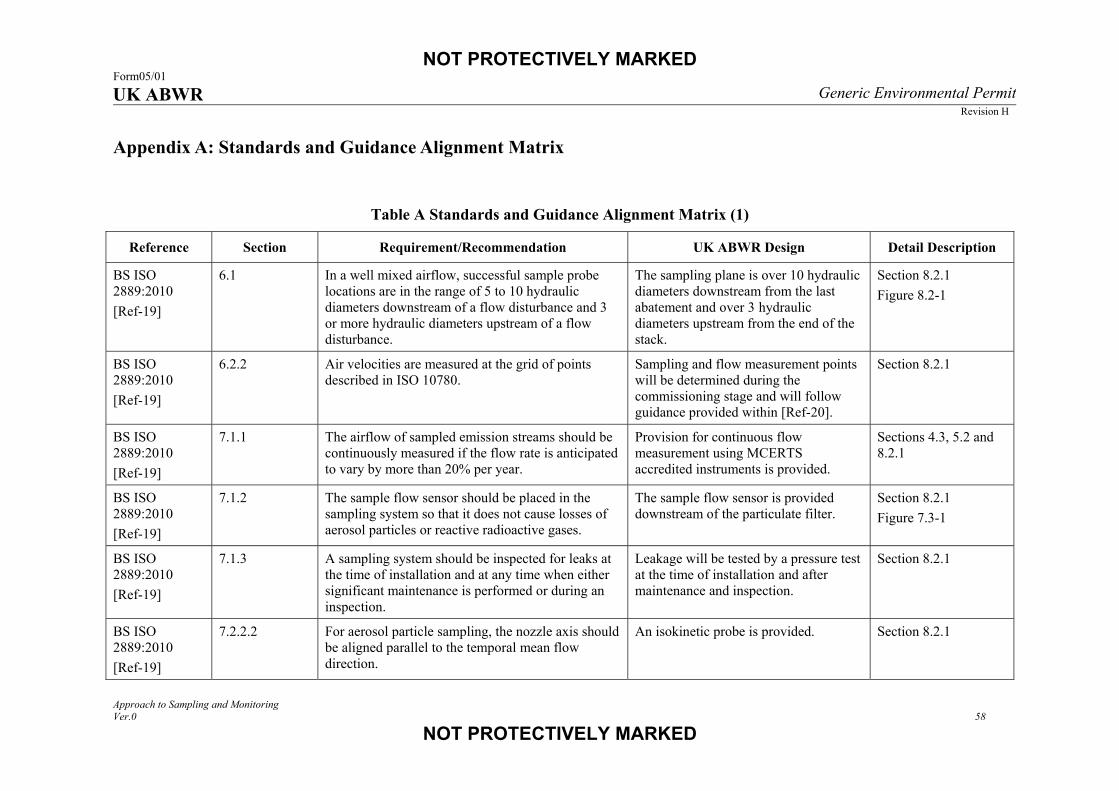
NOT PROTECTIVELY MARKED Form05/01 UK ABWR Generic Environmental Permit
Revision H
Approach to Sampling and Monitoring Ver.0 58
NOT PROTECTIVELY MARKED
Appendix A: Standards and Guidance Alignment Matrix
Table A Standards and Guidance Alignment Matrix (1)
Reference Section Requirement/Recommendation UK ABWR Design Detail Description
BS ISO 2889:2010 [Ref-19]
6.1 In a well mixed airflow, successful sample probe locations are in the range of 5 to 10 hydraulic diameters downstream of a flow disturbance and 3 or more hydraulic diameters upstream of a flow disturbance.
The sampling plane is over 10 hydraulic diameters downstream from the last abatement and over 3 hydraulic diameters upstream from the end of the stack.
Section 8.2.1 Figure 8.2-1
BS ISO 2889:2010 [Ref-19]
6.2.2 Air velocities are measured at the grid of points described in ISO 10780.
Sampling and flow measurement points will be determined during the commissioning stage and will follow guidance provided within [Ref-20].
Section 8.2.1
BS ISO 2889:2010 [Ref-19]
7.1.1 The airflow of sampled emission streams should be continuously measured if the flow rate is anticipated to vary by more than 20% per year.
Provision for continuous flow measurement using MCERTS accredited instruments is provided.
Sections 4.3, 5.2 and 8.2.1
BS ISO 2889:2010 [Ref-19]
7.1.2 The sample flow sensor should be placed in the sampling system so that it does not cause losses of aerosol particles or reactive radioactive gases.
The sample flow sensor is provided downstream of the particulate filter.
Section 8.2.1
Figure 7.3-1
BS ISO 2889:2010 [Ref-19]
7.1.3 A sampling system should be inspected for leaks at the time of installation and at any time when either significant maintenance is performed or during an inspection.
Leakage will be tested by a pressure test at the time of installation and after maintenance and inspection.
Section 8.2.1
BS ISO 2889:2010 [Ref-19]
7.2.2.2 For aerosol particle sampling, the nozzle axis should be aligned parallel to the temporal mean flow direction.
An isokinetic probe is provided. Section 8.2.1
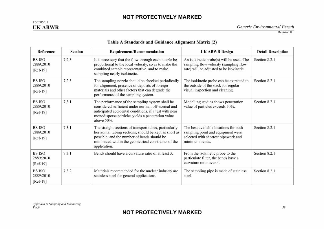
NOT PROTECTIVELY MARKED Form05/01 UK ABWR Generic Environmental Permit
Revision H
Approach to Sampling and Monitoring Ver.0 59
NOT PROTECTIVELY MARKED
Table A Standards and Guidance Alignment Matrix (2)
Reference Section Requirement/Recommendation UK ABWR Design Detail Description
BS ISO 2889:2010 [Ref-19]
7.2.3 It is necessary that the flow through each nozzle be proportional to the local velocity, so as to make the combined sample representative, and to make sampling nearly isokinetic.
An isokinetic probe(s) will be used. The sampling flow velocity (sampling flow rate) will be adjusted to be isokinetic.
Section 8.2.1
BS ISO 2889:2010 [Ref-19]
7.2.5 The sampling nozzle should be checked periodically for alignment, presence of deposits of foreign materials and other factors that can degrade the performance of the sampling system.
The isokinetic probe can be extracted to the outside of the stack for regular visual inspection and cleaning.
Section 8.2.1
BS ISO 2889:2010 [Ref-19]
7.3.1 The performance of the sampling system shall be considered sufficient under normal, off-normal and anticipated accidental conditions, if a test with near monodisperse particles yields a penetration value above 50%.
Modelling studies shows penetration value of particles exceeds 50%.
Section 8.2.1
BS ISO 2889:2010 [Ref-19]
7.3.1 The straight sections of transport tubes, particularly horizontal tubing sections, should be kept as short as possible, and the number of bends should be minimized within the geometrical constraints of the application.
The best available locations for both sampling point and equipment were selected with shortest pipework and minimum bends.
Section 8.2.1
BS ISO 2889:2010 [Ref-19]
7.3.1 Bends should have a curvature ratio of at least 3. From the isokinetic probe to the particulate filter, the bends have a curvature ratio over 4.
Section 8.2.1
BS ISO 2889:2010 [Ref-19]
7.3.2 Materials recommended for the nuclear industry are stainless steel for general applications.
The sampling pipe is made of stainless steel.
Section 8.2.1
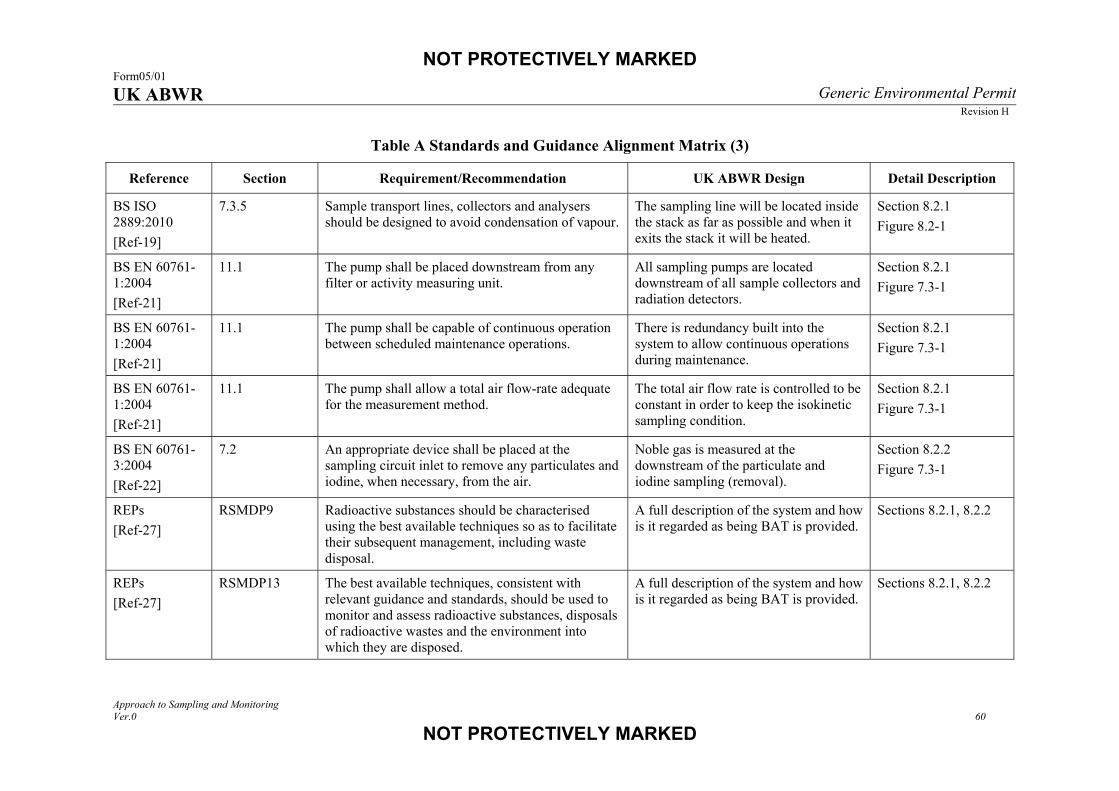
NOT PROTECTIVELY MARKED Form05/01 UK ABWR Generic Environmental Permit
Revision H
Approach to Sampling and Monitoring Ver.0 60
NOT PROTECTIVELY MARKED
Table A Standards and Guidance Alignment Matrix (3)
Reference Section Requirement/Recommendation UK ABWR Design Detail Description
BS ISO 2889:2010
[Ref-19]
7.3.5 Sample transport lines, collectors and analysers should be designed to avoid condensation of vapour.
The sampling line will be located inside the stack as far as possible and when it exits the stack it will be heated.
Section 8.2.1
Figure 8.2-1
BS EN 60761-1:2004
[Ref-21]
11.1 The pump shall be placed downstream from any filter or activity measuring unit.
All sampling pumps are located downstream of all sample collectors and radiation detectors.
Section 8.2.1
Figure 7.3-1
BS EN 60761-1:2004
[Ref-21]
11.1 The pump shall be capable of continuous operation between scheduled maintenance operations.
There is redundancy built into the system to allow continuous operations during maintenance.
Section 8.2.1
Figure 7.3-1
BS EN 60761-1:2004
[Ref-21]
11.1 The pump shall allow a total air flow-rate adequate for the measurement method.
The total air flow rate is controlled to be constant in order to keep the isokinetic sampling condition.
Section 8.2.1
Figure 7.3-1
BS EN 60761-3:2004
[Ref-22]
7.2 An appropriate device shall be placed at the sampling circuit inlet to remove any particulates and iodine, when necessary, from the air.
Noble gas is measured at the downstream of the particulate and iodine sampling (removal).
Section 8.2.2
Figure 7.3-1
REPs
[Ref-27]
RSMDP9 Radioactive substances should be characterised using the best available techniques so as to facilitate their subsequent management, including waste disposal.
A full description of the system and how is it regarded as being BAT is provided.
Sections 8.2.1, 8.2.2
REPs
[Ref-27]
RSMDP13 The best available techniques, consistent with relevant guidance and standards, should be used to monitor and assess radioactive substances, disposals of radioactive wastes and the environment into which they are disposed.
A full description of the system and how is it regarded as being BAT is provided.
Sections 8.2.1, 8.2.2

NOT PROTECTIVELY MARKED Form05/01 UK ABWR Generic Environmental Permit
Revision H
Approach to Sampling and Monitoring Ver.0 61
NOT PROTECTIVELY MARKED
Table A Standards and Guidance Alignment Matrix (4)
Reference Section Requirement/Recommendation UK ABWR Design Detail Description
REPs [Ref-27]
RSMDP14 Sufficient records relating to radioactive substances and associated facilities should be made and managed so as: to facilitate the subsequent management of those substances and facilities; to demonstrate whether compliance with requirements and standards has been achieved; and to provide information and continuing assurance about the environmental impact and risks of the operations undertaken, including waste disposal.
Record keeping will be the responsibility of the future licensee, but the generic design allows for all the data required to be recorded to be collected in a robust manner.
Section 8.1.3
REPs [Ref-27]
ENDP4 Environment protection functions under normal and fault conditions should be identified, and it should be demonstrated that adequate environment protection measures are in place to deliver these functions.
A full description is provided of the different monitoring systems designed to detect radiation levels during normal and fault conditions.
Section 8.3
REPs [Ref-27]
ENDP10 Facilities should be designed and equipped so that best available techniques are used to quantify the gaseous and liquid radioactive discharges produced by each major source on a site.
A full description of the system and how is it regarded as being BAT is provided.
Sections 8.2.1, 8.2.2
REPs [Ref-27]
ENDP10 Considerations
Discharge routes should be provided with suitable means to measure any release of radioactive substances from the facility to the environment, whether the release is routine or accidental.
The discharge routes are identified and monitored.
Section 8.1.2 Figure 7.2-1 Figure 7.2-2
REPs [Ref-27]
ENDP10 Considerations
Wherever practicable, discharge monitoring should occur prior to release into the environment.
Liquid discharge is batch process. Only when the activity has been shown to be below the permitted activity concentrations, the liquid is allowed to be released to the discharge canal.
Sections 7.4, 8.2.1

NOT PROTECTIVELY MARKED Form05/01 UK ABWR Generic Environmental Permit
Revision H
Approach to Sampling and Monitoring Ver.0 62
NOT PROTECTIVELY MARKED
Table A Standards and Guidance Alignment Matrix (5)
Reference Section Requirement/Recommendation UK ABWR Design Detail Description
REPs [Ref-27]
ENDP10 Considerations
Where several discharge routes come together before the point of release to the environment there should be means of monitoring or assessing each route so that the contributions from various sources to discharges to the environment can be quantified.
For gaseous discharge, the OG and TGS have monitoring provisions. If elevated readings are detected at the final discharge point and the OG and TGS are not showing elevated readings the source will be from the HVAC. For liquid discharge, all routes have monitoring provisions.
Section 8.3.3
REPs [Ref-27]
ENDP10 Considerations
Within each facility there should be means to provide early warning of states that could lead to discharges above normal levels for that facility.
Continuous monitoring with an alarm function is provided upstream of the OG charcoal adsorber as well as at the main stack.
Section 8.3.2
REPs [Ref-27]
ENDP14 Best available techniques should be used for the control and measurement of plant parameters and releases to the environment, and for assessing the effects of such releases in the environment.
A full description is provided of the different monitoring systems designed to detect radiation levels during normal and fault conditions.
Section 8
TGN M1 [Ref-29]
Annex 1 As far downstream or upstream from any disturbance, which could produce a change in direction of flow (e.g. bends, fans).
The sampling plane is over 10 hydraulic diameters downstream from the last abatement and over 3 hydraulic diameters upstream from the end of the stack.
Section 8.2.1 Figure 8.2-1
TGN M1 [Ref-29]
Annex 1 In a section of duct with constant shape and cross sectional area.
The sampling plane is located within a vertical straight stack.
Section 8.2.1 Figure 8.2-1

NOT PROTECTIVELY MARKED Form05/01 UK ABWR Generic Environmental Permit
Revision H
Approach to Sampling and Monitoring Ver.0 63
NOT PROTECTIVELY MARKED
Table A Standards and Guidance Alignment Matrix (6)
Reference Section Requirement/Recommendation UK ABWR Design Detail Description
TGN M1 [Ref-29]
Annex 1 Recommend five hydraulic diameters upstream and two hydraulic diameters downstream.
The sampling plane is over 10 hydraulic diameters downstream from the last abatement and over 3 hydraulic diameters upstream from the end of the stack.
Section 8.2.1 Figure 8.2-1
TGN M1 [Ref-29]
Annex 1 Installation of sample plane in vertical stacks is preferred to horizontal ducts.
The sampling plane is located within a vertical straight stack.
Section 8.2.1 Figure 8.2-1
TGN M1 [Ref-29]
Annex 1 It is advised that an exploratory velocity traverse is carried out before committing to installation.
Sampling and flow measurement points will be determined during the commissioning stage and will follow guidance provided within [Ref-20].
Section 8.2.1
TGN M1 [Ref-29]
Annex 1 It is recommended that access ports have a minimum diameter of 125mm.
An access port which meets M1 is provided for independent monitoring.
Section 9.1
TGN M1 [Ref-29]
Annex 1 Additional ports may be required to allow access for measurement of other quantities.
A port for independent monitoring is provided.
Section 9.1
TGN M1 [Ref-29]
Annex 1 Sufficient work area to manipulate probe and operate the measuring instruments, without equipment overhanging guardrails.
The platform is designed so that workers will have safe access for periodic inspection and maintenance.
Section 8.2.1
TGN M1 [Ref-29]
Annex 1 A sufficient depth of work area is given by the internal diameter or depth of the duct and the wall thickness plus 1.5 m.
The minimum requirements for the platform will be a one sided, however, a full circumference platform is possible and will be considered at the site specific stage.
Section 8.2.1

NOT PROTECTIVELY MARKED Form05/01 UK ABWR Generic Environmental Permit
Revision H
Approach to Sampling and Monitoring Ver.0 64
NOT PROTECTIVELY MARKED
Table A Standards and Guidance Alignment Matrix (7)
Reference Section Requirement/Recommendation UK ABWR Design Detail Description
TGN M1 [Ref-29]
Annex 1 Single phase 110V electrical power of a suitable current provided by a suitable number of outdoor waterproof sockets at the platform.
UK standard waterproof sockets of single phase 110 V are provided.
Section 9.1
TGN M11 [Ref-30]
4.1 The amount of radioactivity in the collection device is measured and can be related to the amount of gaseous effluent that has passed through the sampling system in the sampling period to give the activity concentration of the effluent. The total amount of radioactivity emitted can then be estimated from the activity concentration multiplied by the total stack flow during the period.
The sampling and monitoring system is designed to measure the flow rate as well as the activity concentration of the sample to assess the total activity of the discharge. The sampling period will be recorded for each different sampling technique.
Section 8.1.1
TGN M11 [Ref-30]
4.2.1 Sampling must take place downstream of any abatement plant.
All samples are collected close to the top of the stack downstream of all the abatement technologies used within the plant.
Section 8.1.2
Figure 7.2-1
TGN M11 [Ref-30]
4.2.1 The sample must be taken at a position in the emission stack where all constituents are adequately mixed.
The sampling plane is over 10 hydraulic diameters downstream from the last abatement to ensure the flow is well mixed.
Section 8.2.1 Figure 8.2-1
TGN M11 [Ref-30]
4.2.1 The sample must be taken well away from any ductwork features such as dampers, bends and merged streams, which may have a detrimental effect on mixing and flow patterns.
The sampling plane is over 10 hydraulic diameters downstream from the last abatement to ensure the flow is well mixed.
Section 8.2.1 Figure 8.2-1
TGN M11 [Ref-30]
4.2.1 The sample should ideally be taken via a probe and this must be pointing upstream.
The isokinetic probe pointing upstream will be used to collect the sample.
Section 8.2.1 Figure 8.2-1

NOT PROTECTIVELY MARKED Form05/01 UK ABWR Generic Environmental Permit
Revision H
Approach to Sampling and Monitoring Ver.0 65
NOT PROTECTIVELY MARKED
Table A Standards and Guidance Alignment Matrix (8)
Reference Section Requirement/Recommendation UK ABWR Design Detail Description
TGN M11 [Ref-30]
4.2.1 The emission velocity and concentration profiles adjacent to the extract plane should be reasonably uniform.
Sampling and flow measurement points will be determined during the commissioning stage and will follow guidance provided within [Ref-20].
Section 8.2.1
TGN M11
[Ref-30]
4.2.1 A minimum distance of 10 to 20 duct diameters downstream from the last major duct feature is required.
The sampling plane is over 10 hydraulic diameters downstream from the last major duct feature.
Section 8.2.1
Figure 8.2-1
TGN M11
[Ref-30]
4.2.1 It should be normal practice during commissioning to measure both the concentration and the velocity profiles across the duct or stack section to establish the optimum position of the probe.
Concentration and velocity profiles will be measured during commissioning in accordance with [Ref-19][Ref-20].
Section 8.2.1
TGN M11
[Ref-30]
4.2.1 It is necessary to use a probe with a nozzle designed to ensure that isokinetic sampling is taking place and that the sample being taken is truly representative in respect of particle size distribution.
The isokinetic probe is provided to collect representative sample.
Section 8.2.1
TGN M11
[Ref-30]
4.2.3 Samples are analysed retrospectively in the laboratory using counting devices.
Samples collected over the sampling period will be analysed in an appropriately accredited laboratory.
Section 8.2.2
TGN M11
[Ref-30]
5.1 It is particularly important when sampling for particulates and condensable vapours that the length of pipework between the probe and the sample collector is as short as possible in order to minimise condensation/plate-out and avoid unrepresentative sampling.
The sampling equipment is located where the pipework becomes as short as possible.
The sampling line will be located inside the stack as far as possible and when it exits the stack it will be heated.
Section 8.2.1
Figure 8.2-1
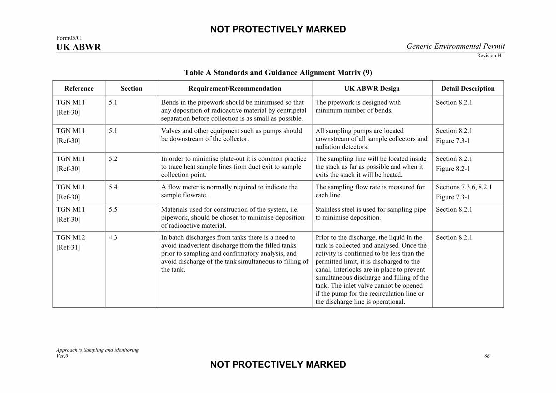
NOT PROTECTIVELY MARKED Form05/01 UK ABWR Generic Environmental Permit
Revision H
Approach to Sampling and Monitoring Ver.0 66
NOT PROTECTIVELY MARKED
Table A Standards and Guidance Alignment Matrix (9)
Reference Section Requirement/Recommendation UK ABWR Design Detail Description
TGN M11
[Ref-30]
5.1 Bends in the pipework should be minimised so that any deposition of radioactive material by centripetal separation before collection is as small as possible.
The pipework is designed with minimum number of bends.
Section 8.2.1
TGN M11
[Ref-30]
5.1 Valves and other equipment such as pumps should be downstream of the collector.
All sampling pumps are located downstream of all sample collectors and radiation detectors.
Section 8.2.1
Figure 7.3-1
TGN M11
[Ref-30]
5.2 In order to minimise plate-out it is common practice to trace heat sample lines from duct exit to sample collection point.
The sampling line will be located inside the stack as far as possible and when it exits the stack it will be heated.
Section 8.2.1
Figure 8.2-1
TGN M11
[Ref-30]
5.4 A flow meter is normally required to indicate the sample flowrate.
The sampling flow rate is measured for each line.
Sections 7.3.6, 8.2.1
Figure 7.3-1
TGN M11
[Ref-30]
5.5 Materials used for construction of the system, i.e. pipework, should be chosen to minimise deposition of radioactive material.
Stainless steel is used for sampling pipe to minimise deposition.
Section 8.2.1
TGN M12
[Ref-31]
4.3 In batch discharges from tanks there is a need to avoid inadvertent discharge from the filled tanks prior to sampling and confirmatory analysis, and avoid discharge of the tank simultaneous to filling of the tank.
Prior to the discharge, the liquid in the tank is collected and analysed. Once the activity is confirmed to be less than the permitted limit, it is discharged to the canal. Interlocks are in place to prevent simultaneous discharge and filling of the tank. The inlet valve cannot be opened if the pump for the recirculation line or the discharge line is operational.
Section 8.2.1

NOT PROTECTIVELY MARKED Form05/01 UK ABWR Generic Environmental Permit
Revision H
Approach to Sampling and Monitoring Ver.0 67
NOT PROTECTIVELY MARKED
Table A Standards and Guidance Alignment Matrix (10)
Reference Section Requirement/Recommendation UK ABWR Design Detail Description
TGN M12
[Ref-31]
5.2.1 A pump is used to mix the contents of the tank via a recirculation line. A single grab sample is then taken on a sample point, usually in the pump recirculation line.
Prior to discharge, a tank is mixed using a recirculation line and then sample is collected.
Section 8.2.1
TGN M12
[Ref-31]
5.2.1 A composite sample of the contents of the tank is taken from the discharge line using a proportional sampler.
The sample is collected using a flow proportional sampler located on the final discharge line.
Section 8.2.1
Figure 7.2-2
TGN M12 [Ref-31]
6.1 Liquid samples must be of sufficient volume to allow all of the required analyses to be carried out, with provision of spare material for repeat analyses.
The exact volume of sample collected will be determined through a combination of the total volume discharged and the laboratory requirements for the volume of sample required. A sampler will be selected that is capable of obtaining a range of volumes.
Sections 8.2.1, 8.2.2
TGN M12 [Ref-31]
6.3 Sampling must be carried out downstream of any abatement plant but upstream of any point where further dilution of the waste stream occurs.
The sample is collected at the final discharge line of the liquid radwaste treatment system before it is diluted in the discharge canal.
Sections 7.4, 8.2.1
Figure 7.2-2
TGN M12 [Ref-31]
6.3 Prior to taking single grab samples, the contents of sentencing or hold up tanks must be mixed and sampling must take place prior to any period during which settling of particulates may occur.
The holdup tanks will be mixed using a recirculation line and the sample will be collected prior to discharge.
Section 7.7